WO2017013897A1 - メタン価算出方法およびメタン価測定装置 - Google Patents
メタン価算出方法およびメタン価測定装置 Download PDFInfo
- Publication number
- WO2017013897A1 WO2017013897A1 PCT/JP2016/057784 JP2016057784W WO2017013897A1 WO 2017013897 A1 WO2017013897 A1 WO 2017013897A1 JP 2016057784 W JP2016057784 W JP 2016057784W WO 2017013897 A1 WO2017013897 A1 WO 2017013897A1
- Authority
- WO
- WIPO (PCT)
- Prior art keywords
- gas
- value
- concentration
- measurement target
- methane number
- Prior art date
- Legal status (The legal status is an assumption and is not a legal conclusion. Google has not performed a legal analysis and makes no representation as to the accuracy of the status listed.)
- Ceased
Links
Images


Classifications
-
- G—PHYSICS
- G01—MEASURING; TESTING
- G01N—INVESTIGATING OR ANALYSING MATERIALS BY DETERMINING THEIR CHEMICAL OR PHYSICAL PROPERTIES
- G01N21/00—Investigating or analysing materials by the use of optical means, i.e. using sub-millimetre waves, infrared, visible or ultraviolet light
- G01N21/17—Systems in which incident light is modified in accordance with the properties of the material investigated
- G01N21/25—Colour; Spectral properties, i.e. comparison of effect of material on the light at two or more different wavelengths or wavelength bands
- G01N21/31—Investigating relative effect of material at wavelengths characteristic of specific elements or molecules, e.g. atomic absorption spectrometry
- G01N21/35—Investigating relative effect of material at wavelengths characteristic of specific elements or molecules, e.g. atomic absorption spectrometry using infrared light
- G01N21/3504—Investigating relative effect of material at wavelengths characteristic of specific elements or molecules, e.g. atomic absorption spectrometry using infrared light for analysing gases, e.g. multi-gas analysis
-
- G—PHYSICS
- G01—MEASURING; TESTING
- G01N—INVESTIGATING OR ANALYSING MATERIALS BY DETERMINING THEIR CHEMICAL OR PHYSICAL PROPERTIES
- G01N33/00—Investigating or analysing materials by specific methods not covered by groups G01N1/00 - G01N31/00
- G01N33/22—Fuels; Explosives
- G01N33/225—Gaseous fuels, e.g. natural gas
-
- G—PHYSICS
- G01—MEASURING; TESTING
- G01N—INVESTIGATING OR ANALYSING MATERIALS BY DETERMINING THEIR CHEMICAL OR PHYSICAL PROPERTIES
- G01N21/00—Investigating or analysing materials by the use of optical means, i.e. using sub-millimetre waves, infrared, visible or ultraviolet light
- G01N21/17—Systems in which incident light is modified in accordance with the properties of the material investigated
- G01N21/25—Colour; Spectral properties, i.e. comparison of effect of material on the light at two or more different wavelengths or wavelength bands
- G01N21/31—Investigating relative effect of material at wavelengths characteristic of specific elements or molecules, e.g. atomic absorption spectrometry
- G01N21/35—Investigating relative effect of material at wavelengths characteristic of specific elements or molecules, e.g. atomic absorption spectrometry using infrared light
- G01N21/3504—Investigating relative effect of material at wavelengths characteristic of specific elements or molecules, e.g. atomic absorption spectrometry using infrared light for analysing gases, e.g. multi-gas analysis
- G01N2021/3509—Correlation method, e.g. one beam alternating in correlator/sample field
Definitions
- the present invention relates to a methane number calculating method and a methane number measuring apparatus.
- a method of calculating the methane number of fuel gas (A) A method proposed by AVL (hereinafter also referred to as “AVL standard”), (B) A method of calculating by a specific arithmetic expression defined by the California Air Resources Council (hereinafter also referred to as “CARB standard”), (C) A method of calculating by a method based on ISO / TR 22302 3.1.1 (hereinafter also referred to as “GRI (Lc) standard”), (D) A method of calculating by a method based on ISO / TR 22302 3.1.2 (hereinafter also referred to as “GRI (H / C) standard”).
- CARB standard California Air Resources Council
- the methane number shows a different value depending on the calculation method even for the same fuel gas. For example, a methane number based on a different standard for each region is required.
- both methods calculate the methane number based on the gas composition, as described above, when the gas composition fluctuates, measure the gas composition when calculating the methane number. Is required.
- natural gas usually contains not only combustible gas components such as paraffinic hydrocarbon gas but also incombustible gas components such as nitrogen gas and carbon dioxide gas. Since there is no law in the degree of influence of these non-combustible gas components on the calorific value, no specific correlation is established between the calorific value (true calorific value) of natural gas and the value of methane number. Moreover, since the concentration ratio of nitrogen gas and carbon dioxide gas contained in natural gas cannot be quantified, calculation errors due to the inclusion of these miscellaneous gas components are inevitably generated. However, as a result of intensive studies by the present inventors, a specific correlation is established between the concentration of nitrogen gas contained in natural gas and the amount of methane number fluctuation (error) caused by the nitrogen gas concentration.
- the present inventors have found that a specific correlation is established between the concentration of carbon dioxide gas contained in natural gas and the variation amount (error) of the methane number caused by the carbon dioxide gas concentration. Then, by performing correction according to each of the nitrogen gas concentration and the carbon dioxide gas concentration, a specific value between the value of the basic calorific value of natural gas and the value of the methane number calculated by the AVL standard, for example, is specified. It has been found that an approximate solution of the methane number corresponding to the AVL standard can be obtained by establishing a correlation and measuring the basic calorific value of the natural gas that is the measurement target gas.
- the “basic heat amount” refers to the amount of combustion heat of the combustible gas component when the non-combustible gas component is removed from the natural gas.
- the present invention has been made based on the circumstances as described above, and for a natural gas that is a measurement object gas, a methane number that can be easily obtained regardless of the gas composition.
- An object is to provide a calculation method.
- the present invention can easily obtain a methane number having a certain degree of reliability for natural gas, which is a measurement target gas, regardless of the gas composition, and can monitor the fuel properties of natural gas used as fuel gas. It aims at providing the methane number measuring apparatus which can be performed.
- a specific relational expression between the methane number and the basic calorific value is obtained in advance for a plurality of kinds of reference gases each having a different methane number value each made of natural gas, While measuring the basic calorific value of the natural gas that is the measurement target gas, the nitrogen gas concentration and the carbon dioxide gas concentration contained in the measurement target gas are measured, The methane number of the measurement target gas is calculated from the basic calorific value of the measurement target gas, the concentration value of the nitrogen gas, the concentration value of the carbon dioxide gas, and the specific relational expression.
- MN is the methane number
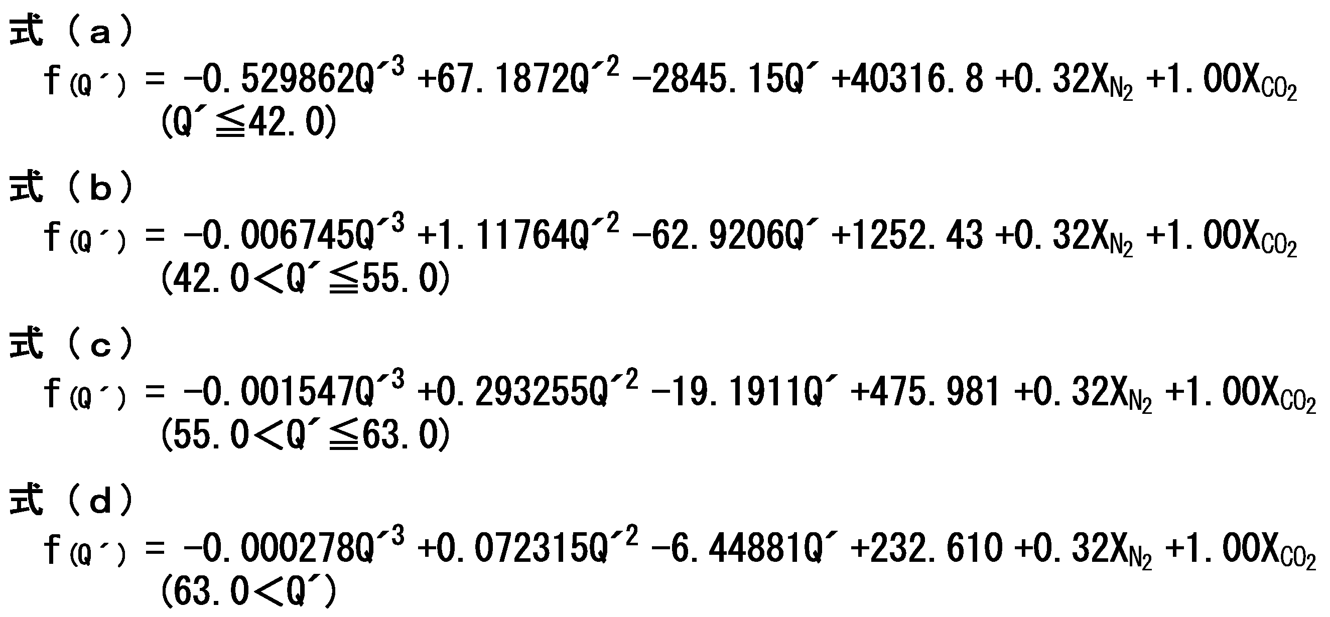
- f (Q ′ ) is selected according to the following formula (a) to the following formula selected according to the value of the basic calorie Q ′ [MJ / m 3 ] of the measurement target gas.
- Any function represented by (d), and A is a value selected from the range of -2.0 to 2.0.
- X N2 is the concentration (vol%) of nitrogen gas contained in the measurement target gas indicated by volume percentage
- X CO2 is included in the measurement target gas indicated by volume percentage.
- concentration of carbon dioxide gas [vol%].
- the basic calorie of the measurement target gas is a refractive index conversion calorie obtained from the refractive index of the measurement target gas, and a sonic conversion calorie obtained from the sound speed of the measurement target gas. It is preferable that it is obtained based on. Furthermore, in the methane number calculation method of the present invention, it is preferable that the concentration of carbon dioxide gas contained in the measurement object gas is measured by an infrared absorption method.
- the methane number measuring device of the present invention is a calorimetric mechanism that measures the basic calorific value of natural gas that is a measurement target gas; A carbon dioxide concentration measuring mechanism for measuring a carbon dioxide gas concentration contained in the measurement target gas; A nitrogen concentration calculation mechanism for calculating the concentration of nitrogen gas contained in the measurement target gas; A specific relational expression between a methane number and a basic calorific value for a plurality of kinds of reference gases made of natural gas, each of which has a different methane value, and the measurement target gas measured by the calorimetric mechanism.
- the methane number of the measurement target gas is calculated from the basic calorific value of the gas, the carbon dioxide gas concentration value measured by the carbon dioxide concentration measuring mechanism, and the nitrogen gas concentration value measured by the nitrogen concentration calculating mechanism. And a methane number calculating mechanism.
- the calorimetric measurement mechanism is based on a refractive index-converted calorie measuring means for obtaining a refractive index-converted calorie from a refractive index value of the measurement target gas, and a sound velocity value of the measurement target gas.
- the apparatus includes a sonic conversion calorie measuring unit for obtaining a sonic conversion calorie, and a calorie calculating unit for calculating the basic calorie of the measurement target gas based on the refractive index conversion calorie and the sonic conversion calorie.
- the carbon dioxide concentration measuring mechanism includes an infrared sensor.
- the methane number of the measurement target gas is calculated based on the value of the measurement target gas basic heat quantity by using a specific relational expression between the basic heat quantity and the methane number acquired in advance.
- the specific relational expression shows the correlation between the basic calorific value and the methane number for various types of reference gas consisting of natural gas with different values of methane number, such as nitrogen gas and carbon dioxide gas contained in natural gas. It is clarified quantitatively by supporting the experiment considering the influence of the gas component on the basic calorific value. For this reason, the obtained methane number has a certain reliability.
- the basic calorific value of the measurement target gas is continuously measured by the calorimetric measurement mechanism, so that the measurement target gas in accordance with the actual situation is measured. Since the methane number can be obtained continuously, the actual fuel properties of natural gas as fuel gas can be monitored. Therefore, when a change in gas composition occurs, a change in methane number accompanying a change in gas composition can be detected quickly.
- FIG. 1 is a block diagram showing an outline of a configuration in an example of a methane number measuring apparatus of the present invention.
- This methane number measuring device uses natural gas as a measurement target gas, a calorific measurement mechanism 20 that measures the calorie of the measurement target gas, a methane number calculation mechanism 40 that calculates the methane number of the measurement target gas, and a measurement target gas
- a display mechanism 45 that displays information such as the amount of heat and the methane number is disposed in the outer container 10, for example.
- the calorific value measuring mechanism 20 includes, for example, a refractive index converted calorific value measuring mechanism 21 for obtaining a refractive index converted calorific value Q O obtained from a refractive index value of natural gas that is a measuring object gas, and a sound velocity value of the measuring object gas.
- the sound velocity conversion calorific value measurement mechanism 25 for obtaining the sound velocity conversion calorie Q S obtained from the above, the carbon dioxide concentration measurement mechanism 50 for measuring the concentration X CO2 of the carbon dioxide gas contained in the measurement target gas, and the measurement target gas A nitrogen concentration calculating mechanism 30 for calculating the concentration X N2 of the nitrogen gas contained therein and a calorific value calculating mechanism 35 for calculating the calorific value Q OS and the basic calorific value Q ′ of the measurement target gas are provided.
- the refractive index converted calorific value measuring mechanism 21 has a refractive index measuring unit 22 that measures the refractive index of the measurement target gas, and a function that calculates the refractive index converted calorie Q O based on the value of the refractive index measured by the refractive index measuring unit 22. And a refractive-index-to-calorie conversion processing means 23.
- the refractive index-heat quantity conversion processing means 23 is for a specific gas consisting only of a combustible gas component (paraffinic hydrocarbon gas) that does not contain an incombustible gas component (for example, N 2 or CO 2 ) in the natural gas that is the measurement target gas.
- the refractive index value obtained for the measurement target gas is the refractive index of the specific gas. calculating the refractive index in terms of the amount of heat Q O by contrast assuming.
- the sonic-converted calorie measuring mechanism 25 is a sonic-velocity measuring unit 26 that measures the propagation speed of sound waves in the measurement-target gas (the sonic velocity of the measurement-target gas), and the sonic-converted calorific value based on the value of the sonic velocity measured by the sonic velocity measuring unit 26.
- Sonic-heat quantity conversion processing means 27 having a function of obtaining the value of Q S is provided.
- the sonic-heat quantity conversion processing means 27 is used for a specific gas consisting only of a combustible gas component (paraffinic hydrocarbon gas) that does not contain a non-combustible gas component (for example, N 2 or CO 2 ) in the natural gas that is the measurement target gas.
- the sound speed value obtained for the measurement target gas is the sound speed of the specific gas.
- the sonic equivalent heat quantity Q S is calculated.
- the carbon dioxide concentration measuring mechanism 50 includes carbon dioxide concentration measuring means 51 that measures the concentration X CO2 of carbon dioxide gas contained in natural gas that is a measurement target gas.
- the carbon dioxide concentration measuring means 51 is not particularly limited, but, for example, the concentration of carbon dioxide gas depending on the degree of attenuation of the amount of infrared light due to absorption of infrared rays by carbon dioxide gas that is a detection target gas. it is preferable to construct the one having an infrared sensor for detecting the X CO2.
- the carbon dioxide concentration measuring means 51 what uses a so-called non-dispersive infrared absorption method is used, so that the influence of other miscellaneous gases contained in the measurement target gas can be minimized.
- the gas concentration X CO2 can be detected with high accuracy.
- Nitrogen concentration calculation mechanism 30 the value of the refractive index in terms heat Q O obtained by the refractive index in terms of calorimetry mechanism 21, and the obtained value of speed of sound in terms heat Q S by the sound velocity in terms calorimetry mechanism 25, the carbon dioxide concentration Based on the carbon dioxide gas concentration X CO2 obtained by the measuring mechanism 50, the correction factor ⁇ is within the range of 1.1 to 4.2, preferably 2.00 to 2 according to the following formula (2).
- the concentration X N2 of the nitrogen gas contained in the natural gas that is the measurement target gas is calculated under the condition that the value selected within the range of .60 is used.
- the value of the correction factor ⁇ is obtained by actually measuring the refractive index converted heat quantity Q O and the sonic speed converted heat quantity Q S for each of miscellaneous gas components (for example, nitrogen gas and carbon dioxide gas) included in the measurement target gas.
- the refractive index-converted heat quantity Q O and sonic-speed converted heat quantity Q S can be set based on the ratio of the error to the heat quantity obtained by analysis using, for example, gas chromatography.
- the value of the correction factor ⁇ varies depending on the type of the miscellaneous gas component contained in the gas to be measured. However, since the value is selected from the above numerical range, the refractive index converted heat quantity Q O and the sound velocity are calculated. Measurement errors that occur in the converted heat quantity Q S can be corrected appropriately.
- X N2 in the above formula (2) is the concentration [vol%] of nitrogen gas expressed as a volume percentage.
- k N2 is an error coefficient for nitrogen gas, and represents the magnitude of the influence of error on N 2 as a miscellaneous gas component on the refractive index measuring means 22.
- k CO2 is an error coefficient for carbon dioxide gas, and represents the magnitude of the influence of error on the refractive index measuring means 22 by CO 2 as a miscellaneous gas component.
- the unit of the value of the refractive index converted heat quantity Q O and the value of the sonic speed converted heat quantity Q S used for the calculation is [MJ / Nm 3 ].
- the unit of the value of the carbon dioxide gas concentration X CO2 is [vol%].
- the error coefficient k N2 for nitrogen gas is a value selected within a range of 20.00 to 30.00, for example. Further, the error coefficient k CO2 for carbon dioxide gas is a value selected within a range of 35.00 to 45.00, for example.
- the error coefficient k N2 for nitrogen gas and the error coefficient k CO2 for carbon dioxide gas are values selected within the above numerical range, the measurement error generated in the refractive index converted heat quantity Q O can be corrected appropriately. it can.
- the value of the error coefficient k N2 for nitrogen gas is, for example, the value obtained by actually measuring the refractive index converted heat quantity Q O by the refractive index converted heat quantity measuring mechanism 21 for nitrogen gas (100 vol%). Can be set based on.
- the value of the error coefficient k CO2 for carbon dioxide gas was obtained by actually measuring the refractive index converted calorific value Q O by the refractive index converted calorific value measuring mechanism 21 for carbon dioxide gas (100 vol%), for example. Can be set based on the value.
- the calorific value calculation mechanism 35 is measured based on the value of the refractive index converted calorific value Q O obtained by the refractive index converted calorific value measuring mechanism 21 and the value of the sonic converted calorific value Q S obtained by the sonic velocity converted calorific value measuring mechanism 25.
- the calorific value Q OS of the natural gas that is the target gas is calculated. Specifically, when the refractive index-converted heat quantity Q O has a magnitude equal to or smaller than the sonic-speed converted heat quantity Q S (Q O ⁇ Q S ), the correction factor ⁇ is 1.1 to 4 according to the following equation (3).
- the value of the calorific value Q OS is calculated under the condition of using a value selected within a range of .2 and preferably within a range of 2.00 to 2.60.
- the value of the refractive index in terms heat Q O is the larger than the value of the sound velocity in terms heat Q S (Q O> Q S ), as the value of the heat quantity Q OS, the value of the refractive index in terms heat Q O is used.
- the calorific value calculation mechanism 35 is obtained by the calorific value Q OS obtained in this way, the carbon dioxide concentration X CO2 value obtained by the carbon dioxide concentration measuring mechanism 50, and the nitrogen concentration calculation mechanism 30. Based on the value of the nitrogen gas concentration X N2 obtained, the value [MJ / Nm 3 ] of the basic calorific value Q ′ is calculated by the following equation (4).
- the methane number calculating mechanism 40 calculates an approximate solution of the methane number MN of the natural gas that is the measurement target gas, specifically, the methane number value obtained by the method based on the AVL standard (reference (a)) described above. .
- the methane number calculating mechanism 40 is obtained by a method based on the AVL standard for a plurality of types of reference gases that has been acquired in advance based on the value of the basic calorific value Q ′ of the measurement target gas measured by the calorific value measuring mechanism 20.
- a methane number MN as an approximate solution of the AVL value for the natural gas that is the measurement target gas is calculated from a specific relational expression between the value of the methane number (AVL value) and the value of the basic heat quantity Q ′.
- the plurality of kinds of reference gases are made of natural gas each having a different methane number MN value based on the AVL standard.
- the specific relational expression is as follows.
- the basic heat quantity Q is determined for each of the plurality of reference gases.
- An actual measurement value indicating the relationship between the value of ′ and the value of the methane number MN can be obtained, and the obtained actual measurement value can be obtained by, for example, approximating a curve with a polynomial.
- the specific relational expression is represented by the above formula (1).
- MN is the methane number, specifically, an approximate solution of the AVL value
- f (Q ′ ) is selected according to the value of the basic heat quantity Q ′ of the measurement target gas.
- X N2 is the concentration (vol%) of nitrogen gas contained in the measurement target gas represented by volume percentage
- X CO2 is contained in the measurement target gas represented by volume percentage. It is the concentration [vol%] of carbon dioxide gas.
- a in the above formula (1) is a value selected from the range of -2.0 to 2.0.
- the methane number is measured for a reference gas having a known composition, and the difference from the theoretical value (AVL value) is set as “A” (offset) Adjustment).
- the term “0.32X N2 ” in the above formulas (a) to (d) indicates the methane number correction amount based on the measured nitrogen gas concentration X N2 .
- the correction amount of the methane number is the concentration [vol%] indicated by the volume percentage of nitrogen gas contained in the measurement target gas, and the ordinate is the methane number (AVL value).
- the coordinate system for each of a plurality of kinds of reference gases having different methane values, an actual measurement value indicating the relationship between the nitrogen gas concentration value X N2 and the AVL value is acquired, and the obtained actual measurement value is linearly approximated, for example. It is set based on the approximate straight line acquired by doing. As is apparent from FIG.
- FIG. 2 is obtained by using a mixed gas of CH 4 , C 2 H 6 , C 3 H 8 and N 2 as the reference gas, in which the concentration of each gas component is appropriately changed. It is.
- the "1.00X CO2" in the above formula (a) ⁇ formula (d) shows the methane number of the correction amount based on the measured carbon dioxide concentration X CO2.
- the correction amount of the methane value by the carbon dioxide gas is set by the same method as the correction amount of the methane value by the nitrogen gas.
- the approximate curves for the respective reference gases have the same magnitude of inclination, and the magnitude of this inclination is set as the correction coefficient “1.00” for carbon dioxide gas. ing.
- the natural gas that is the measurement target gas may contain, for example, oxygen gas as a miscellaneous gas component.
- oxygen gas as a miscellaneous gas component.
- the amount of oxygen gas contained in natural gas is very small, the influence of methane number on oxygen gas can be substantially ignored.
- reference numeral 11 in FIG. 1 denotes a measurement target gas introduction unit for supplying the measurement target gas to each of the refractive index measurement means 22, the sound velocity measurement means 26, and the carbon dioxide concentration measurement means 51, and 12 denotes a refractive index measurement means.
- Reference numeral 22 is a reference gas introduction section for introducing a reference gas required for the detection principle, and 13 is a gas discharge section.
- the dashed-two dotted line in FIG. 1 shows gas piping.
- a part of natural gas that is connected to a gas pipeline through an appropriate gas sampling device and circulates in the gas pipeline is measured from the measurement target gas introduction unit 11 as a measurement target gas.
- the sound velocity measuring means 26 of the converted calorific value measuring mechanism 25 and the refractive index measuring means 22 of the refractive index converted calorific value measuring mechanism 21 are sequentially supplied.
- a reference gas such as air is supplied from the reference gas introduction unit 12 to the refractive index measuring means 22 of the refractive index converted calorific value measuring mechanism 21.
- the refractive index conversion calorie measuring mechanism 21 the refractive index of natural gas is measured by the refractive index measuring means 22, and based on the result, the refractive index converted heat quantity Q O is obtained by the refractive index-heat quantity conversion processing means 23. It is done.
- the sonic-converted calorie measuring mechanism 25 the sonic velocity of natural gas is measured by the sonic velocity measuring means 26, and the value of the sonic-converted calorific value Q S is obtained by the sonic velocity-calorie conversion processing means 27 based on the result.
- all the other natural gas introduced from the measurement target gas introduction unit 11 is supplied to the carbon dioxide concentration measuring means 51 of the carbon dioxide concentration measuring mechanism 50.
- the concentration X CO2 [vol% (volume percentage)] of the carbon dioxide gas contained in the natural gas is measured by the carbon dioxide concentration measuring means 51.
- the correction factor ⁇ is specified by the above formula (2) and the above formula (3).
- the nitrogen gas concentration X N2 and the heat quantity Q OS are calculated.
- the basic calorific value Q ′ of the measurement target gas is calculated by the above equation (4).
- the specific relational expression selected from the methane number calculation mechanism 40 according to the value of the basic calorie Q ′ obtained by the calorie measurement mechanism 20 (any one of the expressions (a) to (d))
- the methane number MN as an approximate solution of the AVL value is calculated, and the result is displayed on the display mechanism 45. Note that the measurement target gas and the reference gas are discharged to the outside of the apparatus through the gas discharge unit 13.
- the methane number MN of the measurement target gas is calculated by using a specific relational expression between the basic heat quantity Q ′ and the methane number MN acquired in advance. It can be determined based on the basic heat quantity Q ′.
- the specific relational expression shows the correlation between the basic calorific value and the AVL value with respect to a plurality of kinds of reference gases made of natural gas each having a different methane value (AVL value) based on the AVL standard. This is quantitatively clarified through experimental support, taking into account the effects of the inclusion of carbon gas. For this reason, the obtained methane number MN has a certain reliability.
- the basic calorific value Q ′ of the measurement target gas is continuously measured by the calorie measuring mechanism 20, thereby obtaining an actual situation. Since the methane number MN as an approximate solution of the AVL value of the measurement target gas can be continuously obtained, the actual fuel property of the natural gas as the fuel gas can be monitored. Therefore, when a change in gas composition occurs, a change in methane number MN accompanying a change in gas composition can be detected quickly.
- the calorific value measuring mechanism 20 and the methane number calculating mechanism 40 are arranged in the outer container 10, so that the measurement system is easily constructed and operated.
- the measurement does not take a considerable amount of time, and since no time lag occurs between the calculation process of the basic heat quantity Q ′ and the calculation process of the methane number MN, the methane number MN is measured in real time. be able to.
- the calorific value measuring mechanism 20 is configured to calculate the calorific value of the measurement target gas based on the two converted calorific values, ie, the refractive index converted calorific value Q O and the sonic velocity converted calorific value Q S , so that the obtained calorific value Q OS Is a value having a small difference from the true value of the calorific value of the measurement target gas regardless of the gas composition of the measurement target gas, and thus the reliability of the calculated value of the methane number MN is further increased.
- the calorific measurement mechanism is not limited to the one having the above-described configuration, and an apparatus having a configuration for obtaining a calorific value based on a thermal conductivity converted calorific value and a refractive index converted calorific value. May be used. Further, one of the physical property values having a specific correspondence with the amount of heat, for example, one selected from refractive index, thermal conductivity, and sound velocity is measured, and the amount of heat is obtained based on the measured value. May be.
- the value of the above formula (b) and the basic heat quantity Q ′ is larger than 55.0 [MJ / Nm 3 ] and 63.0 [MJ / Nm 3 ].
- the correction factor ⁇ in the above equations (2) and (3) is 2.24
- the error coefficient k N2 for nitrogen gas in equation (2) is 26.06
- the error coefficient k CO2 for carbon dioxide gas is 40.53.
- the sample gas mainly composed of paraffinic hydrocarbon gas and containing nitrogen gas and carbon dioxide gas as miscellaneous gas components, regardless of the composition of the sample gas. It was confirmed that a methane number (approximate solution) having a value within a certain error range (within ⁇ 2.8) with respect to the methane number according to the AVL standard can be obtained.
- the measured methane number is a value in the range of, for example, ⁇ 3.0 of the methane number according to the AVL standard, there is no problem in practice.
- the present invention can detect in real time a change in fuel properties such as a change in methane number and a change in calorific value due to a change in gas composition of natural gas as a fuel gas, combustion control of a natural gas fuel engine It is expected to be extremely useful when performing
Landscapes
- Chemical & Material Sciences (AREA)
- Physics & Mathematics (AREA)
- Health & Medical Sciences (AREA)
- Life Sciences & Earth Sciences (AREA)
- Analytical Chemistry (AREA)
- Immunology (AREA)
- Spectroscopy & Molecular Physics (AREA)
- Pathology (AREA)
- General Physics & Mathematics (AREA)
- General Health & Medical Sciences (AREA)
- Engineering & Computer Science (AREA)
- Biochemistry (AREA)
- Chemical Kinetics & Catalysis (AREA)
- Medicinal Chemistry (AREA)
- Oil, Petroleum & Natural Gas (AREA)
- Food Science & Technology (AREA)
- General Chemical & Material Sciences (AREA)
- Investigating Or Analysing Materials By Optical Means (AREA)
- Other Investigation Or Analysis Of Materials By Electrical Means (AREA)
- Investigating Or Analyzing Materials By The Use Of Ultrasonic Waves (AREA)
Abstract
Description
天然ガスを利用したガスエンジンの実用化に係る課題としては、天然ガスの組成が産出地により異なる点や、ガスエンジンの起動時や負荷変動時に燃料ガスの消費量の変動が生ずることによって燃料ガスの組成が変化する点などが挙げられる。燃料ガスの組成が変わると、燃料ガスの熱量やメタン価などの特性が変化し、エンジンのノッキングや失火などの異常燃焼を引き起こす原因になりうる。ここで、メタン価とは、ガソリンエンジンのオクタン価に対応するノッキングに対する抵抗値を示す指標であって、純メタンを100、水素を0として評価した指標である。
(a)AVL社が提案する方式(以下、「AVL基準」ともいう。)、
(b)カリフォルニア州大気資源評議会で規定された特定の演算式により算出する方式(以下、「CARB基準」ともいう。)、
(c)ISO/TR 22302 3.1.1に準拠した方法により算出する方式(以下、「GRI(Lc)基準」ともいう。)、
(d)ISO/TR 22302 3.1.2に準拠した方法により算出する方式(以下、「GRI(H/C)基準」ともいう。)
の4種類が主に利用されている。ここに、メタン価は、同一の燃料ガスであっても、算出方法によって異なる値を示し、例えば地域ごとに異なる基準によるメタン価が要請されている。
しかしながら、いずれの方法も、メタン価をガス組成に基づいて算出するものであることから、上述したように、ガス組成の変動が生じた場合には、メタン価の算出にあたってガス組成を測定することが必要となる。
然るに、本発明者らが鋭意研究を重ねた結果、天然ガスに含まれる窒素ガス濃度と、当該窒素ガス濃度に起因するメタン価の変動量(誤差)との間に特定の相関関係が成立すること、並びに、天然ガスに含まれる二酸化炭素ガス濃度と、当該二酸化炭素ガス濃度に起因するメタン価の変動量(誤差)との間に特定の相関関係が成立することを見出した。そして、窒素ガス濃度および二酸化炭素ガスの各々の濃度に応じた補正を行うことにより、天然ガスの基礎熱量の値と、例えば上記のAVL基準により算出されるメタン価の値との間に特定の相関関係が成立し、測定対象ガスである天然ガスの基礎熱量を測定することにより、当該AVL基準に対応するメタン価の近似解を得ることができることを見出した。ここに、「基礎熱量」とは、天然ガスから不燃ガス成分を除いたときの燃焼性ガス成分の燃焼熱量をいう。
また、本発明は、測定対象ガスである天然ガスについて、一応の信頼性を有するメタン価をガス組成に拘わらず容易に得ることができ、燃料ガスとして利用される天然ガスの燃料性状の監視を行うことのできるメタン価測定装置を提供することを目的とする。
測定対象ガスである天然ガスの基礎熱量を測定すると共に、当該測定対象ガスに含まれる窒素ガス濃度および二酸化炭素ガス濃度を測定し、
当該測定対象ガスの基礎熱量の値、当該窒素ガスの濃度値および当該二酸化炭素ガスの濃度値と、前記特定の関係式とから当該測定対象ガスのメタン価を算出することを特徴とする。

さらにまた、本発明のメタン価算出方法においては、前記測定対象ガスに含まれる二酸化炭素ガスの濃度が、赤外線吸収法により測定されることが好ましい。
当該測定対象ガスに含まれる二酸化炭素ガス濃度を測定する二酸化炭素濃度測定機構と、
当該測定対象ガスに含まれる窒素ガス濃度を算出する窒素濃度計算機構と、
予め取得しておいた、各々メタン価の値が異なる天然ガスよりなる複数種の基準ガスについてのメタン価と基礎熱量との特定の関係式と、前記熱量測定機構により測定された当該測定対象ガスの基礎熱量の値、前記二酸化炭素濃度測定機構により測定された二酸化炭素ガス濃度の値および前記窒素濃度計算機構により測定された窒素ガス濃度の値とから、当該測定対象ガスのメタン価を算出するメタン価算出機構と
を備えることを特徴とする。
さらにまた、本発明のメタン価測定装置においては、前記二酸化炭素濃度測定機構は、赤外式センサを備えたものであることが好ましい。
図1は、本発明のメタン価測定装置の一例における構成の概略を示すブロック図である。
このメタン価測定装置は、天然ガスを測定対象ガスとし、測定対象ガスの熱量を測定する熱量測定機構20と、当該測定対象ガスのメタン価を算出するメタン価算出機構40と、測定対象ガスの熱量およびメタン価などの情報を表示する表示機構45とが、例えば外装容器10内に配設されて構成されている。
屈折率-熱量換算処理手段23は、測定対象ガスである天然ガスにおいて不燃ガス成分(例えばN2 やCO2 など)を含まない燃焼性ガス成分(パラフィン系炭化水素ガス)のみからなる特定ガスについて、例えばグラフ化することなどによって予め取得された屈折率と熱量との相関関係を利用し、当該相関関係に対して、測定対象ガスについて得られた屈折率の値が特定ガスの屈折率であると仮定して対照することにより屈折率換算熱量QO を算出する。
音速-熱量換算処理手段27は、測定対象ガスである天然ガスにおいて不燃ガス成分(例えばN2 やCO2 など)を含まない燃焼性ガス成分(パラフィン系炭化水素ガス)のみからなる特定ガスについて、例えばグラフ化することなどによって予め取得された音速と熱量との相関関係を利用し、当該相関関係に対して、測定対象ガスについて得られた音速の値が特定ガスの音速である仮定して対照することにより音速換算熱量QS を算出する。
二酸化炭素濃度測定手段51としては、特に限定されるものではないが、例えば、赤外線が検知対象ガスである二酸化炭素ガスによって吸収されることによる赤外線光量の減衰の程度に応じて二酸化炭素ガスの濃度XCO2 を検出する赤外式センサを備えたものにより構成することが好ましい。二酸化炭素濃度測定手段51として、いわゆる非分散型赤外線吸収法を利用したものが用いられることにより、測定対象ガスに含まれる他の雑ガスの影響を可及的に小さくすることができ、二酸化炭素ガスの濃度XCO2 を高い精度で検出することができる。

具体的には、窒素ガスについての誤差係数kN2 の値は、例えば窒素ガス(100vol%)について実際に屈折率換算熱量測定機構21によって屈折率換算熱量QO を測定し、得られた値に基づいて設定することができる。また、二酸化炭素ガスについての誤差係数kCO2 の値についても同様に、例えば二酸化炭素ガス(100vol%)について実際に屈折率換算熱量測定機構21によって屈折率換算熱量QO を測定し、得られた値に基づいて設定することができる。


メタン価算出機構40は、熱量測定機構20により測定された測定対象ガスの基礎熱量Q´の値に基づいて、予め取得しておいた、複数種の基準ガスについての、AVL基準に基づく方法により得られるメタン価の値(AVL値)と基礎熱量Q´の値との特定の関係式から、測定対象ガスである天然ガスについてのAVL値の近似解としてのメタン価MNを算出する。複数種の基準ガスは、各々AVL基準に基づくメタン価MNの値が異なる天然ガスよりなるものである。
上記式(1)におけるAの値の具体的な設定方法としては、例えば、組成が既知の基準ガスについてメタン価を測定し、理論値(AVL値)との差分を「A」として設定(オフセット調整)することができる。
一方、測定対象ガス導入部11から導入された天然ガスの他の全部が、二酸化炭素濃度測定機構50の二酸化炭素濃度測定手段51に供給される。これにより、二酸化炭素濃度測定機構50において、天然ガスに含まれる二酸化炭素ガスの濃度XCO2 〔vol%(体積百分率)〕が二酸化炭素濃度測定手段51によって測定される。
次いで、メタン価算出機構40によって、熱量測定機構20によって得られた基礎熱量Q´の値に応じて選択される上記特定の関係式(式(a)~式(d)のいずれかの関数)に基づいて、AVL値の近似解としてのメタン価MNが算出され、その結果が表示機構45に表示される。
なお、測定対象ガスおよび参照ガスは、ガス排出部13を介して装置外部に排出される。
従って、このようなメタン価算出方法が実行される上記構成のメタン価測定装置によれば、熱量測定機構20によって測定対象ガスの基礎熱量Q´を連続的に測定することにより、実際の状況に即した測定対象ガスのAVL値の近似解としてのメタン価MNを連続的に取得することができるので、燃料ガスとしての天然ガスの実際の燃料性状の監視を行うことができる。従って、ガス組成の変動が生じた場合には、ガス組成の変動に伴うメタン価MNの変動を速やかに検出することができる。
本発明においては、熱量測定機構は、上記構成のものに限定されるものではなく、熱伝導率換算熱量の値と、屈折率換算熱量の値とに基づいて熱量の値を求める構成を有する装置が用いられていてもよい。また、熱量と特定の対応関係を有する物性値の1つ、例えば屈折率、熱伝導率、音速のうちから選ばれる1つを測定し、その測定値に基づいて熱量を求める構成のものであってもよい。このようにして得られた測定対象ガスの熱量に基づいて算出される基礎熱量の値を利用しても、各基準に基づくメタン価の値に対して所定の許容範囲内のメタン価を得ることができる。
下記表1に示すガス組成を有する19種類(A~S)の試料ガスを用意し、図1に示す構成のメタン価測定装置を用いて、各々の試料ガスA~Sのメタン価を測定した。メタン価の算出においては、上記式(1)においてA=0とした特定の関係式を利用した。そして、試料ガスの基礎熱量Q´の値が42.0〔MJ/Nm3 〕以下の範囲である場合には上記式(a)、基礎熱量Q´の値が42.0〔MJ/Nm3 〕より大きく、55.0〔MJ/Nm3 〕以下の範囲である場合には上記式(b)、基礎熱量Q´の値が55.0〔MJ/Nm3 〕より大きく、63.0〔MJ/Nm3 〕以下の範囲である場合には上記式(c)、基礎熱量Q´の値が63.0〔MJ/Nm3 〕より大きい範囲である場合には上記式(d)をそれぞれ選択した。また、上記式(2)および式(3)における補正因子αを2.24とし、式(2)における窒素ガスについての誤差係数kN2 を26.06、二酸化炭素ガスについての誤差係数kCO2 を40.53とした。
そして、試料ガスA~Sの各々について、AVL基準に基づく方法(AVL社製のメタン価算出ソフト)によって、ガス組成に基づいて算出されるメタン価を真値としたときの、基礎熱量に基づいて算出されたメタン価の値(熱量換算値)の当該真値に対する誤差を算出した。結果を下記表1に示す。誤差は、熱量換算値から真値を減算することにより得られた値である。
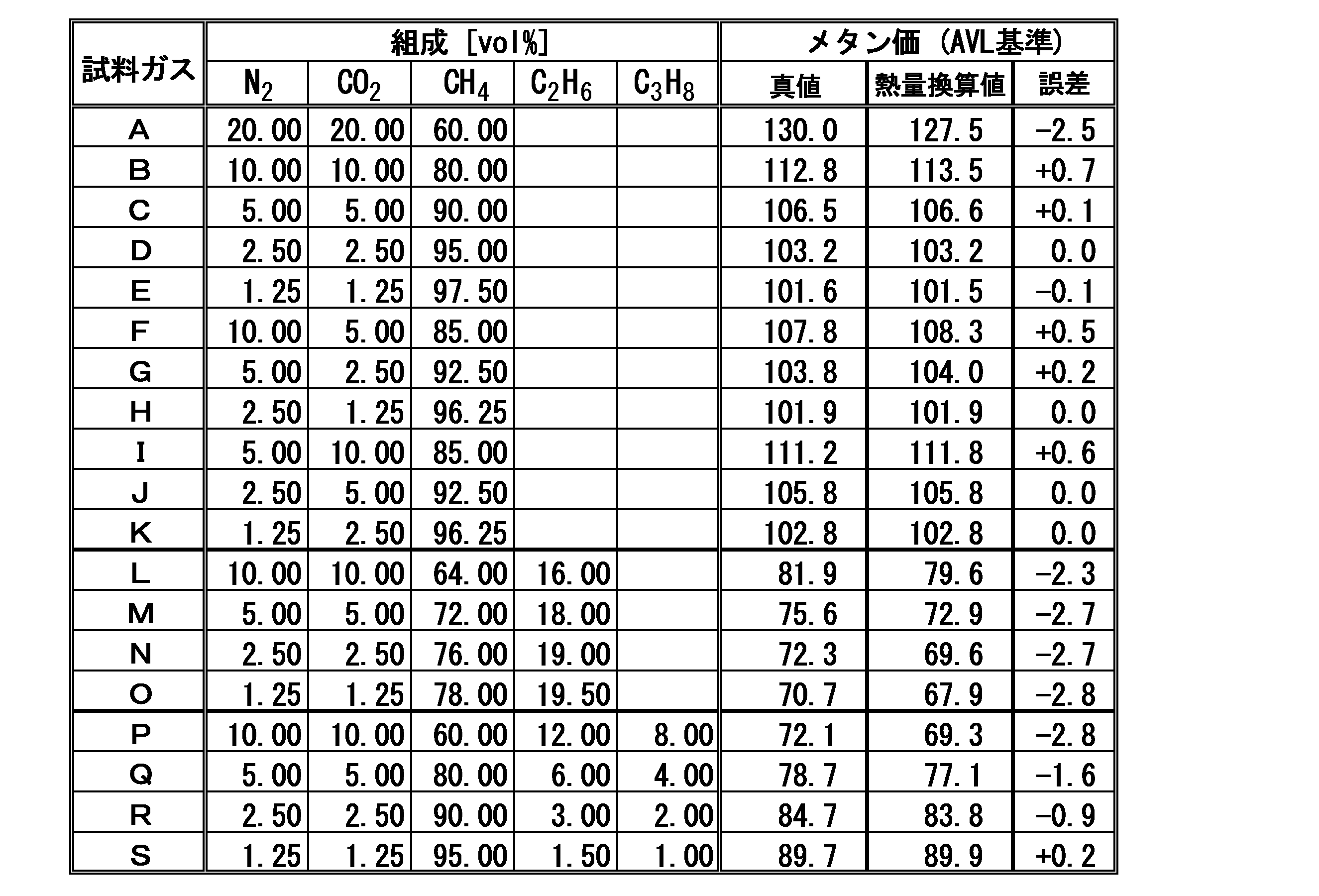
ここに、測定されるメタン価は、AVL基準に係るメタン価の例えば±3.0の範囲程度の値であれば、実際上は問題がないものである。
11 測定対象ガス導入部
12 参照ガス導入部
13 ガス排出部
20 熱量測定機構
21 屈折率換算熱量測定機構
22 屈折率測定手段
23 屈折率-熱量換算処理手段
25 音速換算熱量測定機構
26 音速測定手段
27 音速-熱量換算処理手段
30 窒素濃度計算機構
35 熱量計算機構
40 メタン価算出機構
45 表示機構
50 二酸化炭素濃度測定機構
51 二酸化炭素濃度測定手段
Claims (8)
- 各々天然ガスよりなる互いにメタン価の値が異なる複数種の基準ガスについてのメタン価と基礎熱量との特定の関係式を予め取得しておき、
測定対象ガスである天然ガスの基礎熱量を測定すると共に、当該測定対象ガスに含まれる窒素ガス濃度および二酸化炭素ガス濃度を測定し、
当該測定対象ガスの基礎熱量の値、当該窒素ガスの濃度値および当該二酸化炭素ガスの濃度値と、前記特定の関係式とから当該測定対象ガスのメタン価を算出することを特徴とするメタン価算出方法。 - 前記特定の関係式として、下記式(1)で表されるものが用いられることを特徴とする請求項1に記載のメタン価算出方法。


- 前記測定対象ガスの基礎熱量は、当該測定対象ガスの屈折率から得られる屈折率換算熱量と、当該測定対象ガスの音速から得られる音速換算熱量とに基づいて得られるものであることを特徴とする請求項1または請求項2に記載のメタン価算出方法。
- 前記測定対象ガスに含まれる二酸化炭素ガスの濃度が、赤外線吸収法により測定されることを特徴とする請求項1乃至請求項3のいずれかに記載のメタン価算出方法。
- 測定対象ガスである天然ガスの基礎熱量を測定する熱量測定機構と、
当該測定対象ガスに含まれる二酸化炭素ガス濃度を測定する二酸化炭素濃度測定機構と、
当該測定対象ガスに含まれる窒素ガス濃度を算出する窒素濃度計算機構と、
予め取得しておいた、各々メタン価の値が異なる天然ガスよりなる複数種の基準ガスについてのメタン価と基礎熱量との特定の関係式と、前記熱量測定機構により測定された当該測定対象ガスの基礎熱量の値、前記二酸化炭素濃度測定機構により測定された二酸化炭素ガス濃度の値および前記窒素濃度計算機構により測定された窒素ガス濃度の値とから、当該測定対象ガスのメタン価を算出するメタン価算出機構と
を備えることを特徴とするメタン価測定装置。 - 前記特定の関係式が、下記式(1)で表されるものであることを特徴とする請求項5に記載のメタン価測定装置。


- 前記熱量測定機構が、測定対象ガスの屈折率の値から屈折率換算熱量を求める屈折率換算熱量測定手段と、当該測定対象ガスの音速の値から音速換算熱量を求める音速換算熱量測定手段と、当該測定対象ガスの基礎熱量を、屈折率換算熱量、音速換算熱量、二酸化炭素濃度および窒素ガス濃度に基づいて算出する熱量算出手段とを備えることを特徴とする請求項5または請求項6に記載のメタン価測定装置。
- 前記二酸化炭素濃度測定機構は、赤外式センサを備えたものであることを特徴とする請求項5乃至請求項7のいずれかに記載のメタン価測定装置。
Priority Applications (5)
| Application Number | Priority Date | Filing Date | Title |
|---|---|---|---|
| EP16827462.9A EP3327436B1 (en) | 2015-07-22 | 2016-03-11 | Methane number calculation method and methane number measurement device |
| CN201680007079.8A CN107209164B (zh) | 2015-07-22 | 2016-03-11 | 甲烷值计算方法及甲烷值测定装置 |
| US15/531,664 US10132746B2 (en) | 2015-07-22 | 2016-03-11 | Methane number calculation method and methane number measurement device |
| KR1020177016218A KR102405159B1 (ko) | 2015-07-22 | 2016-03-11 | 메탄가 산출 방법 및 메탄가 측정 장치 |
| JP2017529470A JP6759206B2 (ja) | 2015-07-22 | 2016-03-11 | メタン価算出方法およびメタン価測定装置 |
Applications Claiming Priority (2)
| Application Number | Priority Date | Filing Date | Title |
|---|---|---|---|
| JP2015144620 | 2015-07-22 | ||
| JP2015-144620 | 2015-07-22 |
Publications (1)
| Publication Number | Publication Date |
|---|---|
| WO2017013897A1 true WO2017013897A1 (ja) | 2017-01-26 |
Family
ID=57834227
Family Applications (1)
| Application Number | Title | Priority Date | Filing Date |
|---|---|---|---|
| PCT/JP2016/057784 Ceased WO2017013897A1 (ja) | 2015-07-22 | 2016-03-11 | メタン価算出方法およびメタン価測定装置 |
Country Status (6)
| Country | Link |
|---|---|
| US (1) | US10132746B2 (ja) |
| EP (1) | EP3327436B1 (ja) |
| JP (1) | JP6759206B2 (ja) |
| KR (1) | KR102405159B1 (ja) |
| CN (1) | CN107209164B (ja) |
| WO (1) | WO2017013897A1 (ja) |
Cited By (10)
| Publication number | Priority date | Publication date | Assignee | Title |
|---|---|---|---|---|
| WO2019005356A1 (en) * | 2017-06-26 | 2019-01-03 | Mustang Sampling, Llc | SYSTEMS AND METHODS FOR GENERATING METHANE INDEX |
| JP2019045434A (ja) * | 2017-09-07 | 2019-03-22 | 理研計器株式会社 | ガス分析方法およびガス分析装置 |
| WO2019187710A1 (ja) * | 2018-03-28 | 2019-10-03 | 理研計器株式会社 | ガス検出方法およびガス検出装置 |
| WO2019186794A1 (ja) * | 2018-03-28 | 2019-10-03 | 理研計器株式会社 | ガス検出方法およびガス検出装置 |
| WO2020148927A1 (ja) * | 2019-01-17 | 2020-07-23 | 理研計器株式会社 | 組成分析装置および組成分析方法 |
| CN112098356A (zh) * | 2020-08-28 | 2020-12-18 | 长江大学 | 基于红外光谱的甲烷流体包裹体捕获压力的计算方法 |
| JP2021004891A (ja) * | 2020-09-25 | 2021-01-14 | 理研計器株式会社 | メタン濃度算出方法およびメタン濃度測定装置 |
| WO2021256356A1 (ja) * | 2020-06-15 | 2021-12-23 | 理研計器株式会社 | 熱量測定装置および熱量算出方法 |
| JP2021196263A (ja) * | 2020-06-15 | 2021-12-27 | 理研計器株式会社 | メタン価測定装置およびメタン価算出方法 |
| WO2022224297A1 (ja) * | 2021-04-19 | 2022-10-27 | 理研計器株式会社 | 算出装置、算出方法およびプログラム |
Families Citing this family (5)
| Publication number | Priority date | Publication date | Assignee | Title |
|---|---|---|---|---|
| JP6402387B2 (ja) * | 2015-06-11 | 2018-10-10 | 理研計器株式会社 | 熱量測定装置および熱量測定方法 |
| CN111328372B (zh) * | 2019-01-17 | 2021-05-07 | 理研计器株式会社 | 组成分析装置及组成分析方法 |
| DE102019117427A1 (de) * | 2019-06-27 | 2020-12-31 | EnBW Energie Baden-Württemberg AG | Verfahren zur Brennwertbestimmung, Verfahren zur Energiemengenbestimmung eines Gases und Vorrichtung hierzu |
| CN112279211B (zh) * | 2020-10-15 | 2022-11-11 | 上海迪勤智能科技有限公司 | 油气回收检测方法和系统 |
| US12486748B2 (en) | 2022-04-26 | 2025-12-02 | Liberty Oilfield Services Llc | Hybrid oilfield pumping system |
Citations (6)
| Publication number | Priority date | Publication date | Assignee | Title |
|---|---|---|---|---|
| JPS54130990A (en) * | 1978-03-31 | 1979-10-11 | Osaka Gas Co Ltd | Device for measuring gas calorie |
| JPH10185887A (ja) * | 1996-12-24 | 1998-07-14 | Osaka Gas Co Ltd | 供給熱量測定方法、供給熱量測定装置及びガス製造設備 |
| US20020124630A1 (en) * | 1998-02-28 | 2002-09-12 | Manfred Jaeschke | Process for determining the gas composition of the fuel gas |
| JP2009042216A (ja) * | 2007-07-19 | 2009-02-26 | Riken Keiki Co Ltd | 熱量測定方法および熱量測定装置 |
| WO2010013303A1 (ja) * | 2008-07-28 | 2010-02-04 | 東京瓦斯株式会社 | ガス供給システムと供給方法 |
| JP2011502250A (ja) * | 2007-10-31 | 2011-01-20 | アヌビス, ベーヴェーベーアー | 炭化水素燃料の発熱量および相対密度を決定するための方法ならびに装置 |
Family Cites Families (8)
| Publication number | Priority date | Publication date | Assignee | Title |
|---|---|---|---|---|
| US5822058A (en) * | 1997-01-21 | 1998-10-13 | Spectral Sciences, Inc. | Systems and methods for optically measuring properties of hydrocarbon fuel gases |
| EP0967483A2 (de) * | 1998-05-20 | 1999-12-29 | N.V. Nederlandse Gasunie | Verfahren zur verbrennungslosen Bestimmung des Brennwertes von Brenngas |
| CA2362605A1 (en) * | 1999-02-25 | 2000-08-31 | Tadeusz M. Drzewiecki | Methods and apparatus for real time fluid analysis |
| EP1063525A3 (en) * | 1999-06-04 | 2003-12-17 | N.V. Nederlandse Gasunie | Method for measuring the quantity of heat present in fuel gas |
| ATE284532T1 (de) * | 2000-09-29 | 2004-12-15 | E On Ruhrgas Ag | Verfahren und vorrichtung zum ermitteln der gasbeschaffenheit eines erdgases |
| FR2827961B1 (fr) | 2001-07-30 | 2004-01-23 | Dalkia | Methode de determination d'au moins une propriete energetique d'un melange combustible gazeux par mesure de proprietes physiques du melange gazeux |
| DE10231269B4 (de) * | 2002-07-10 | 2013-11-07 | Elster Gmbh | Bestimmung der Gasbeschaffenheit von Brenngasen durch Messung von Wärmeleitfähigkeit, Wärmekapazität und Kohlendioxidanteil |
| US9291610B2 (en) * | 2013-05-06 | 2016-03-22 | Gas Technology Institute | Method and apparatus for real-time measurement of fuel gas compositions and heating values |
-
2016
- 2016-03-11 WO PCT/JP2016/057784 patent/WO2017013897A1/ja not_active Ceased
- 2016-03-11 JP JP2017529470A patent/JP6759206B2/ja active Active
- 2016-03-11 CN CN201680007079.8A patent/CN107209164B/zh active Active
- 2016-03-11 EP EP16827462.9A patent/EP3327436B1/en active Active
- 2016-03-11 US US15/531,664 patent/US10132746B2/en active Active
- 2016-03-11 KR KR1020177016218A patent/KR102405159B1/ko active Active
Patent Citations (6)
| Publication number | Priority date | Publication date | Assignee | Title |
|---|---|---|---|---|
| JPS54130990A (en) * | 1978-03-31 | 1979-10-11 | Osaka Gas Co Ltd | Device for measuring gas calorie |
| JPH10185887A (ja) * | 1996-12-24 | 1998-07-14 | Osaka Gas Co Ltd | 供給熱量測定方法、供給熱量測定装置及びガス製造設備 |
| US20020124630A1 (en) * | 1998-02-28 | 2002-09-12 | Manfred Jaeschke | Process for determining the gas composition of the fuel gas |
| JP2009042216A (ja) * | 2007-07-19 | 2009-02-26 | Riken Keiki Co Ltd | 熱量測定方法および熱量測定装置 |
| JP2011502250A (ja) * | 2007-10-31 | 2011-01-20 | アヌビス, ベーヴェーベーアー | 炭化水素燃料の発熱量および相対密度を決定するための方法ならびに装置 |
| WO2010013303A1 (ja) * | 2008-07-28 | 2010-02-04 | 東京瓦斯株式会社 | ガス供給システムと供給方法 |
Non-Patent Citations (2)
| Title |
|---|
| See also references of EP3327436A4 * |
| TAKURO MATSUSHITA ET AL.: "Genba Needs o Tsuikyu shita Field Keiso Tool -Kaihatsu no Nerai to Un'yo [Kaihatsu·Donyu Jirei] Zatsu Gas Seibun no Eikyo o Jokyo suru Netsuryo Sokutei Gijutsu", KEISO, vol. 53, no. 5, 1 May 2010 (2010-05-01), pages 64 - 66, XP009503884 * |
Cited By (20)
| Publication number | Priority date | Publication date | Assignee | Title |
|---|---|---|---|---|
| US10976295B2 (en) | 2017-06-26 | 2021-04-13 | Mustang Sampling Llc | System and methods for methane number generation |
| WO2019005356A1 (en) * | 2017-06-26 | 2019-01-03 | Mustang Sampling, Llc | SYSTEMS AND METHODS FOR GENERATING METHANE INDEX |
| JP2020524739A (ja) * | 2017-06-26 | 2020-08-20 | ムスタング サンプリング, エルエルシーMustang Sampling, Llc | メタン価生成用のシステムおよび方法 |
| RU2737602C1 (ru) * | 2017-06-26 | 2020-12-01 | Мустанг Сэмплинг Ллк | Системы и способы для генерации метанового числа |
| JP7027465B2 (ja) | 2017-06-26 | 2022-03-01 | ムスタング サンプリング, エルエルシー | メタン価生成用のシステムおよび方法 |
| JP2019045434A (ja) * | 2017-09-07 | 2019-03-22 | 理研計器株式会社 | ガス分析方法およびガス分析装置 |
| WO2019187710A1 (ja) * | 2018-03-28 | 2019-10-03 | 理研計器株式会社 | ガス検出方法およびガス検出装置 |
| WO2019186794A1 (ja) * | 2018-03-28 | 2019-10-03 | 理研計器株式会社 | ガス検出方法およびガス検出装置 |
| JP2019174435A (ja) * | 2018-03-28 | 2019-10-10 | 理研計器株式会社 | ガス検出方法およびガス検出装置 |
| WO2020148927A1 (ja) * | 2019-01-17 | 2020-07-23 | 理研計器株式会社 | 組成分析装置および組成分析方法 |
| US11193917B2 (en) | 2019-01-17 | 2021-12-07 | Riken Keiki Co., Ltd. | Composition analysis apparatus and composition analysis method |
| WO2021256356A1 (ja) * | 2020-06-15 | 2021-12-23 | 理研計器株式会社 | 熱量測定装置および熱量算出方法 |
| JP2021196263A (ja) * | 2020-06-15 | 2021-12-27 | 理研計器株式会社 | メタン価測定装置およびメタン価算出方法 |
| JP7445531B2 (ja) | 2020-06-15 | 2024-03-07 | 理研計器株式会社 | メタン価測定装置およびメタン価算出方法 |
| CN112098356A (zh) * | 2020-08-28 | 2020-12-18 | 长江大学 | 基于红外光谱的甲烷流体包裹体捕获压力的计算方法 |
| CN112098356B (zh) * | 2020-08-28 | 2023-09-15 | 长江大学 | 基于红外光谱的甲烷流体包裹体捕获压力的计算方法 |
| JP2021004891A (ja) * | 2020-09-25 | 2021-01-14 | 理研計器株式会社 | メタン濃度算出方法およびメタン濃度測定装置 |
| JP7523301B2 (ja) | 2020-09-25 | 2024-07-26 | 理研計器株式会社 | メタン濃度測定装置およびメタン濃度測定方法 |
| WO2022224297A1 (ja) * | 2021-04-19 | 2022-10-27 | 理研計器株式会社 | 算出装置、算出方法およびプログラム |
| GB2620331A (en) * | 2021-04-19 | 2024-01-03 | Riken Keiki Kk | Calculation device, calculation method, and program |
Also Published As
| Publication number | Publication date |
|---|---|
| KR20180031623A (ko) | 2018-03-28 |
| EP3327436A4 (en) | 2018-08-01 |
| US10132746B2 (en) | 2018-11-20 |
| KR102405159B1 (ko) | 2022-06-02 |
| CN107209164B (zh) | 2020-12-08 |
| EP3327436A1 (en) | 2018-05-30 |
| CN107209164A (zh) | 2017-09-26 |
| JP6759206B2 (ja) | 2020-09-23 |
| JPWO2017013897A1 (ja) | 2018-04-26 |
| EP3327436B1 (en) | 2022-01-12 |
| US20170370831A1 (en) | 2017-12-28 |
Similar Documents
| Publication | Publication Date | Title |
|---|---|---|
| KR102405159B1 (ko) | 메탄가 산출 방법 및 메탄가 측정 장치 | |
| JP6402387B2 (ja) | 熱量測定装置および熱量測定方法 | |
| JP6702885B2 (ja) | メタン価算出方法およびメタン価測定装置 | |
| Nativel et al. | Laminar flame speeds of pentanol isomers: An experimental and modeling study | |
| JP5782454B2 (ja) | 燃焼性ガスの比重測定方法および比重測定装置並びにウォッベ指数測定装置 | |
| EP3454059B1 (en) | Gas analysis method and gas analyzer | |
| JP6530575B1 (ja) | 組成分析装置および組成分析方法 | |
| JP5308842B2 (ja) | 熱量測定方法および熱量測定装置 | |
| JP5316143B2 (ja) | 排気ガス分析装置 | |
| JP7523301B2 (ja) | メタン濃度測定装置およびメタン濃度測定方法 | |
| WO2012141252A1 (ja) | 気体燃料計測装置及びガスタービン制御システム | |
| CN111328372B (zh) | 组成分析装置及组成分析方法 | |
| WO2019187710A1 (ja) | ガス検出方法およびガス検出装置 | |
| JP2006047071A (ja) | 液化天然ガスの熱量計測方法及び装置 | |
| JP5184983B2 (ja) | 熱量測定方法および熱量測定装置 | |
| JP7445531B2 (ja) | メタン価測定装置およびメタン価算出方法 | |
| WO2019186794A1 (ja) | ガス検出方法およびガス検出装置 | |
| EP4328585B1 (en) | Calculation device, calculation method, and program | |
| WO2003038393A1 (en) | Obtaining exhaust emisissions data |
Legal Events
| Date | Code | Title | Description |
|---|---|---|---|
| 121 | Ep: the epo has been informed by wipo that ep was designated in this application |
Ref document number: 16827462 Country of ref document: EP Kind code of ref document: A1 |
|
| ENP | Entry into the national phase |
Ref document number: 2017529470 Country of ref document: JP Kind code of ref document: A |
|
| WWE | Wipo information: entry into national phase |
Ref document number: 15531664 Country of ref document: US |
|
| REEP | Request for entry into the european phase |
Ref document number: 2016827462 Country of ref document: EP |
|
| ENP | Entry into the national phase |
Ref document number: 20177016218 Country of ref document: KR Kind code of ref document: A |
|
| NENP | Non-entry into the national phase |
Ref country code: DE |