WO2017014107A1 - 紙葉類処理装置 - Google Patents
紙葉類処理装置 Download PDFInfo
- Publication number
- WO2017014107A1 WO2017014107A1 PCT/JP2016/070561 JP2016070561W WO2017014107A1 WO 2017014107 A1 WO2017014107 A1 WO 2017014107A1 JP 2016070561 W JP2016070561 W JP 2016070561W WO 2017014107 A1 WO2017014107 A1 WO 2017014107A1
- Authority
- WO
- WIPO (PCT)
- Prior art keywords
- unit
- conveyance path
- paper sheet
- temporary storage
- banknotes
- Prior art date
- Legal status (The legal status is an assumption and is not a legal conclusion. Google has not performed a legal analysis and makes no representation as to the accuracy of the status listed.)
- Ceased
Links
Images


Classifications
-
- G—PHYSICS
- G07—CHECKING-DEVICES
- G07D—HANDLING OF COINS OR VALUABLE PAPERS, e.g. TESTING, SORTING BY DENOMINATIONS, COUNTING, DISPENSING, CHANGING OR DEPOSITING
- G07D9/00—Counting coins; Handling of coins not provided for in the other groups of this subclass
-
- G—PHYSICS
- G07—CHECKING-DEVICES
- G07D—HANDLING OF COINS OR VALUABLE PAPERS, e.g. TESTING, SORTING BY DENOMINATIONS, COUNTING, DISPENSING, CHANGING OR DEPOSITING
- G07D11/00—Devices accepting coins; Devices accepting, dispensing, sorting or counting valuable papers
- G07D11/10—Mechanical details
- G07D11/16—Handling of valuable papers
- G07D11/18—Diverting into different paths or containers
-
- B—PERFORMING OPERATIONS; TRANSPORTING
- B65—CONVEYING; PACKING; STORING; HANDLING THIN OR FILAMENTARY MATERIAL
- B65H—HANDLING THIN OR FILAMENTARY MATERIAL, e.g. SHEETS, WEBS, CABLES
- B65H43/00—Use of control, checking, or safety devices, e.g. automatic devices comprising an element for sensing a variable
-
- B—PERFORMING OPERATIONS; TRANSPORTING
- B65—CONVEYING; PACKING; STORING; HANDLING THIN OR FILAMENTARY MATERIAL
- B65H—HANDLING THIN OR FILAMENTARY MATERIAL, e.g. SHEETS, WEBS, CABLES
- B65H5/00—Feeding articles separated from piles; Feeding articles to machines
- B65H5/06—Feeding articles separated from piles; Feeding articles to machines by rollers or balls, e.g. between rollers
- B65H5/062—Feeding articles separated from piles; Feeding articles to machines by rollers or balls, e.g. between rollers between rollers or balls
-
- G—PHYSICS
- G07—CHECKING-DEVICES
- G07D—HANDLING OF COINS OR VALUABLE PAPERS, e.g. TESTING, SORTING BY DENOMINATIONS, COUNTING, DISPENSING, CHANGING OR DEPOSITING
- G07D11/00—Devices accepting coins; Devices accepting, dispensing, sorting or counting valuable papers
-
- G—PHYSICS
- G07—CHECKING-DEVICES
- G07D—HANDLING OF COINS OR VALUABLE PAPERS, e.g. TESTING, SORTING BY DENOMINATIONS, COUNTING, DISPENSING, CHANGING OR DEPOSITING
- G07D11/00—Devices accepting coins; Devices accepting, dispensing, sorting or counting valuable papers
- G07D11/10—Mechanical details
- G07D11/12—Containers for valuable papers
- G07D11/125—Secure containers
-
- G—PHYSICS
- G07—CHECKING-DEVICES
- G07D—HANDLING OF COINS OR VALUABLE PAPERS, e.g. TESTING, SORTING BY DENOMINATIONS, COUNTING, DISPENSING, CHANGING OR DEPOSITING
- G07D11/00—Devices accepting coins; Devices accepting, dispensing, sorting or counting valuable papers
- G07D11/10—Mechanical details
- G07D11/12—Containers for valuable papers
- G07D11/13—Containers for valuable papers with internal means for handling valuable papers
-
- G—PHYSICS
- G07—CHECKING-DEVICES
- G07D—HANDLING OF COINS OR VALUABLE PAPERS, e.g. TESTING, SORTING BY DENOMINATIONS, COUNTING, DISPENSING, CHANGING OR DEPOSITING
- G07D11/00—Devices accepting coins; Devices accepting, dispensing, sorting or counting valuable papers
- G07D11/50—Sorting or counting valuable papers
-
- B—PERFORMING OPERATIONS; TRANSPORTING
- B65—CONVEYING; PACKING; STORING; HANDLING THIN OR FILAMENTARY MATERIAL
- B65H—HANDLING THIN OR FILAMENTARY MATERIAL, e.g. SHEETS, WEBS, CABLES
- B65H2601/00—Problem to be solved or advantage achieved
- B65H2601/20—Avoiding or preventing undesirable effects
- B65H2601/25—Damages to handled material
- B65H2601/255—Jam
-
- B—PERFORMING OPERATIONS; TRANSPORTING
- B65—CONVEYING; PACKING; STORING; HANDLING THIN OR FILAMENTARY MATERIAL
- B65H—HANDLING THIN OR FILAMENTARY MATERIAL, e.g. SHEETS, WEBS, CABLES
- B65H2701/00—Handled material; Storage means
- B65H2701/10—Handled articles or webs
- B65H2701/19—Specific article or web
- B65H2701/1912—Banknotes, bills and cheques or the like
-
- G—PHYSICS
- G07—CHECKING-DEVICES
- G07D—HANDLING OF COINS OR VALUABLE PAPERS, e.g. TESTING, SORTING BY DENOMINATIONS, COUNTING, DISPENSING, CHANGING OR DEPOSITING
- G07D11/00—Devices accepting coins; Devices accepting, dispensing, sorting or counting valuable papers
- G07D11/10—Mechanical details
- G07D11/14—Inlet or outlet ports
-
- G—PHYSICS
- G07—CHECKING-DEVICES
- G07D—HANDLING OF COINS OR VALUABLE PAPERS, e.g. TESTING, SORTING BY DENOMINATIONS, COUNTING, DISPENSING, CHANGING OR DEPOSITING
- G07D2207/00—Paper-money testing devices
-
- G—PHYSICS
- G07—CHECKING-DEVICES
- G07D—HANDLING OF COINS OR VALUABLE PAPERS, e.g. TESTING, SORTING BY DENOMINATIONS, COUNTING, DISPENSING, CHANGING OR DEPOSITING
- G07D2211/00—Paper-money handling devices
-
- G—PHYSICS
- G07—CHECKING-DEVICES
- G07D—HANDLING OF COINS OR VALUABLE PAPERS, e.g. TESTING, SORTING BY DENOMINATIONS, COUNTING, DISPENSING, CHANGING OR DEPOSITING
- G07D7/00—Testing specially adapted to determine the identity or genuineness of valuable papers or for segregating those which are unacceptable, e.g. banknotes that are alien to a currency
Definitions
- the present invention relates to a paper sheet processing apparatus.
- This application claims priority based on Japanese Patent Application No. 2015-142881 for which it applied on July 17, 2015, and uses the content here.
- banknotes received from the depositing unit and identified by the identification unit are temporarily stored in the temporary storage unit, and after various processes are completed, the banknotes are transported from the temporary storage unit to the storage unit and stored.
- a banknote processing apparatus is known (see, for example, Patent Document 1).
- a depositing unit is disposed in front of the apparatus, a temporary storage unit is disposed below the depositing unit, and an identification unit is disposed behind the apparatus. Yes. Further, the depositing unit, the identification unit, and the temporary holding unit are connected via an annular conveyance path having a plurality of bent portions.
- the identification unit is arranged behind the device, the temporary storage unit is arranged in front of the device, and the identification unit and the temporary storage unit are connected via the annular conveyance path.
- the banknotes identified by the identification unit are deviated in a substantially U-shape to be bent and conveyed to the temporary storage unit, such as being conveyed to the front of the apparatus after being once conveyed to the rear of the apparatus through the annular conveyance path. . For this reason, since the conveyance distance from an identification part to a temporary storage part is long, and also many bending parts, a branch part, etc. pass in a conveyance path, possibility that jam will generate
- an object of the present invention is to provide a paper sheet processing apparatus that can suppress the occurrence of jam.
- a sheet processing apparatus includes an identification unit that identifies a sheet, a temporary storage unit that temporarily stores the identified sheet, and the identification A straight conveyance path that connects the sheet and the temporary storage unit, extends in a straight line, and conveys the paper sheets identified by the identification unit to the temporary storage unit.
- the identification unit and the temporary storage unit are connected by a straight conveyance path that extends in a straight line, and the paper sheets identified by the identification unit are conveyed to the temporary storage unit by the linear conveyance path. For this reason, paper sheets are not curvedly conveyed from the identification unit to the temporary storage unit. Therefore, the occurrence of jam can be suppressed.
- the paper sheet processing apparatus 10 processes banknotes as paper sheets. You may process paper sheets other than the paper sheet processing apparatus 10 and a banknote.
- the paper sheet processing apparatus 10 is a banknote depositing / withdrawing apparatus capable of performing a depositing process for storing a bill inserted from the outside and a dispensing process for allowing the banknote stored therein to be withdrawn to the outside. It is.
- “front” indicates the operator side
- “rear” indicates the opposite side of the operator
- “left” indicates the left as viewed from the operator
- “right” indicates the operator. Shows right.
- the paper sheet processing apparatus 10 includes a loading unit 11 provided at the upper part on the front side, into which a banknote for depositing is loaded from the outside.
- the paper sheet processing apparatus 10 has a payout unit 12 provided above and behind the input unit 11.
- the dispensing unit 12 can take out these banknotes to the outside.
- the feeding unit 11 and the dispensing unit 12 are provided by overlapping (matching) the positions in the height direction (vertical direction, height direction of the sheet processing apparatus 10), and the positions in the front-rear direction are also superimposed. (Together).
- the paper sheet processing apparatus 10 has an operation display unit 14 provided behind the dispensing unit 12 on the upper surface.
- the operation display unit 14 is of a touch panel type, and accepts an operation input from the operator and displays it to the operator.
- the paper sheet processing apparatus 10 includes an identification unit 17 provided behind the input unit 11.
- the identification unit 17 identifies the banknote, and is provided by overlapping (matching) the insertion unit 11 and the position in the height direction.
- the paper sheet processing apparatus 10 includes a temporary storage unit 18 provided behind the identification unit 17.
- the temporary storage unit 18 is provided to temporarily store the banknotes identified by the identification unit 17 and to superimpose (accumulate) the input unit 11 and the identification unit 17 in the height direction.
- the lower portion of the insertion portion 11 and the upper portion of the identification portion 17 are overlapped (matched) in the height direction.
- the upper part of the insertion part 11 and the lower part of the identification part 17 are shifted in the height direction.
- middle part of the temporary storage part 18 to the lower part have overlapped the position of a height direction (it puts together).
- the upper portion of the temporary storage unit 18 is shifted in the height direction with respect to the identification unit 17.
- the upper part of the temporary storage unit 18 overlaps (combines) the lower part of the dispensing unit 12 with the position in the height direction.
- the input unit 11, the identification unit 17, and the temporary storage unit 18 are arranged in the order of the input unit 11, the identification unit 17, and the temporary storage unit 18 from the front to the rear of the paper sheet processing apparatus 10.
- the input unit 11 and the identification unit 17 are completely displaced in the front-rear direction.
- the positions of the identification unit 17 and the temporary storage unit 18 are completely shifted in the front-rear direction (horizontal direction, front-rear direction of the paper sheet processing apparatus 10 and direction perpendicular to the height direction of the paper sheet processing apparatus 10).
- the loading unit 11 is provided with a mounting plate 19 in a rearwardly lowered posture.
- the mounting plate 19 is moved upward in the throwing portion 11 and moved downward in the forward direction.
- Stacked banknotes are placed from the outside on the placing plate 19 in the state after the lowering operation.
- the loading plate 19 rises and conveys the stacked banknotes in the backward direction, and feeds the stacked banknotes one by one from the top banknote in the stacking direction to the inside of the sheet processing apparatus 10.
- a deposit conveyance path 21 ⁇ / b> A that conveys banknotes fed from the insertion unit 11 is connected to the rear end of the insertion unit 11.
- the deposit conveyance path 21A includes an inclined feeding path portion 21Aa that extends rearward and downward from the input section 11, and a horizontal feeding path portion 21Ab that extends horizontally rearward from the rear end of the inclined feeding path portion 21Aa.
- the deposit conveyance path 21A is connected to the identification unit 17 at the rear end portion of the horizontal path portion 21Ab.
- the identification unit 17 has an internal conveyance path 21B that is arranged on the same straight line as the horizontal path part 21Ab of the deposit conveyance path 21A and extends horizontally rearward from the rear end of the horizontal path part 21Ab.
- the internal conveyance path 21B conveys banknotes continuously from the horizontal transmission path portion 21Ab.
- the identification unit 17 identifies the authenticity, correctness, denomination, denomination, double feed, skew feeding, and the like of the bill being conveyed on the internal conveyance path 21B.
- a straight conveyance path 21C extends horizontally rearward from the rear end of the internal conveyance path 21B of the identification unit 17.
- the rear end portion of the straight conveyance path 21 ⁇ / b> C is connected to the temporary storage unit 18.
- the straight conveyance path 21 ⁇ / b> C continues to convey bills backward from the internal conveyance path 21 ⁇ / b> B.
- the horizontal transfer path 21Ab, the internal transfer path 21B, and the straight transfer path 21C of the deposit transfer path 21A are aligned on the same straight line.
- the identification unit 17 and the temporary storage unit 18 are connected by a straight straight conveyance path 21C. That is, the straight conveyance path is connected to the identification unit 17 and the temporary storage unit 18 and extends in a straight line.
- the straight conveyance path 21 ⁇ / b> C has a front end (first end) connected to the identification unit 17 and a rear end (second end) connected to the temporary storage unit 18, from the rear end to the front end. It extends in a straight line horizontally.
- a bill inserted into the input unit 11 is conveyed from the input unit 11 toward the identification unit 17 through the deposit conveyance path 21A, and after identification by the identification unit 17, is conveyed to the temporary storage unit 18 through the linear conveyance path 21C. That is, the straight conveyance path 21 ⁇ / b> C horizontally conveys the banknote from the identification unit 17 to the temporary storage unit 18 while maintaining the vertical position of the banknote identified by the identification unit 17.
- the straight conveyance path 21 ⁇ / b> C conveys the banknote from the identification unit 17 to the temporary storage unit 18 while maintaining the state in which the banknote identified by the identification unit 17 is not curved.
- the identification unit 17 and the temporary storage unit 18 overlap each other in the height direction. That is, the position of the identification unit 17 in the vertical direction is aligned with the position of the temporary storage unit 18 in the vertical direction.
- the straight conveyance path 21 ⁇ / b> C extends in the horizontal direction, specifically in the horizontal direction, and connects the identification unit 17 and the temporary storage unit 18.
- the temporary storage unit 18 temporarily stores banknotes, takes in and stores the banknotes transported in the linear transport path 21C one by one, and feeds the stored banknotes one by one to the linear transport path 21C.
- the temporary storage unit 18 is a wound storage type in which banknotes are wound around a drum together with tape and stored, and banknotes are unwound from the drum together with tape.
- the withdrawal conveyance path 21D branches upward from an intermediate position (intermediate position) of the straight conveyance path 21C.
- This withdrawal conveyance path 21 ⁇ / b> D is connected to the dispensing unit 12.
- the straight conveyance path 21C can be used as a front transmission section 21Ca on the front side of the branching position of the withdrawal conveyance path 21D and a rearward transmission on the rear side of the branching position of the withdrawal conveyance path 21D. It is divided into the road portion 21Cb.
- a banknote can be transferred between the front-side path portion 21Ca and the rear-side path portion 21Cb.
- the withdrawal conveyance path 21D conveys the banknotes conveyed in the straight conveyance path 21C to the dispensing unit 12.
- the withdrawal conveyance path 21D includes a vertical path part 21Da, a horizontal path part 21Db, a vertical path part 21Dc, and a horizontal path part 21Dd.
- the vertical feed path 21Da extends vertically upward from an intermediate position (halfway position) of the straight conveyance path 21C.
- the horizontal path portion 21Db extends horizontally forward from the upper end portion of the vertical path portion 21Da.
- the vertical channel portion 21Dc extends vertically upward from the front end portion of the horizontal channel portion 21Db.
- the horizontal path portion 21Dd extends horizontally forward from the upper end portion of the vertical path portion 21Dc and is connected to the payout portion 12.
- the dispensing unit 12 accumulates the banknotes fed from the horizontal feeding unit 21Dd of the dispensing conveyance path 21D obliquely from the front side and the lower side to the rear side and the upper side.
- the banknotes accumulated in the dispensing unit 12 are taken out from the dispensing unit 12 to the outside.
- the withdrawal conveyance path 21D is a conveyance path that branches upward from the middle of the straight conveyance path 21C. Therefore, for example, the withdrawal conveyance path 21 ⁇ / b> D conveys the banknotes fed from the temporary storage unit 18 to the straight conveyance path 21 ⁇ / b> C upward from the middle of the straight conveyance path 21 ⁇ / b> C and discharges it to the dispensing unit 12.
- the upper unit 25 constitutes the upper part of the paper sheet processing apparatus 10.
- the upper unit 25 includes an input unit 11, a payout unit 12, an operation display unit 14, an identification unit 17 including an internal conveyance path 21B, a temporary storage unit 18, a deposit conveyance path 21A, a straight conveyance path 21C, and a withdrawal conveyance path 21D.
- an input unit 11 a payout unit 12
- an operation display unit 14 an identification unit 17 including an internal conveyance path 21B, a temporary storage unit 18, a deposit conveyance path 21A, a straight conveyance path 21C, and a withdrawal conveyance path 21D.
- the lower unit 26 is provided on the lower side of the upper unit 25 and constitutes the lower part from the intermediate part in the height direction of the paper sheet processing apparatus 10.
- the lower unit 26 includes a front cassette 31 provided at the front position and a storage 32 provided behind the front cassette 31.
- the storage boxes 32 are arranged in two rows in the vertical direction and in four rows in the front-back direction.
- the upper four units have the same position in the height direction.
- the lower four units are also aligned in the height direction.
- the height of the front cassette 31 is equal to the height of the two storage boxes 32.
- the front cassette 31 overlaps (matches) the two-stage storage bins 32 arranged in the vertical direction with the position in the height direction.
- the vertical transport path 21E branches downward from an intermediate position (halfway position) of the horizontal feed path 21Ab of the deposit transport path 21A.
- This vertical transport path 21E extends vertically downward from the horizontal feed path 21Ab and is connected to the front cassette 31.
- the horizontal conveyance path 21Ab of the deposit conveyance path 21A has a front side configuration part 21Ab1 on the front side of the branch position of the vertical conveyance path 21E and a rear side behind the branch position of the vertical conveyance path 21E. It is divided into a side component 21Ab2. Between the front side component 21Ab1 and the rear side component 21Ab2, it is possible to transport bills from the front side component 21Ab1 to the rear side component 21Ab2.
- a banknote can be transferred between the up-and-down conveyance path 21E and the rear side component 21Ab2.
- the vertical conveyance path 21E is a conveyance path branched downward from the middle of the deposit conveyance path 21A on the side opposite to the linear conveyance path 21C of the identification unit 17. Therefore, the up-and-down conveyance path 21E, for example, conveys the banknote that has been fed from the temporary storage unit 18 to the straight conveyance path 21C and passed through the identification unit 17 from the middle of the deposit conveyance path 21A to be stored in the front cassette 31.
- the front cassette 31 can receive and store banknotes one by one, and can feed out banknotes stored one by one.
- the front cassette 31 is a stacking and storing type that accepts banknotes from the upper part and stores them in a horizontal state by stacking them from the bottom to the top and feeding out the banknotes stored from the banknotes at the upper end.
- the storage cassette front cassette 31 has a bill storage efficiency that is significantly higher than that of a wrapping storage type such as the temporary storage section 18 and a storage 32 described later.
- the storage transport path 21F is branched backward.
- the storage conveyance path 21F extends horizontally rearward from the vertical conveyance path 21E, then extends downward near the rear end portion of the paper sheet processing apparatus 10, and is connected to the upper storage bin 32 at the rear end. Further, the storage conveyance path 21 ⁇ / b> F is connected to the lower storage 32 at the rear end via the upper storage 32 at the rear end.
- the vertical conveyance path 21E has an upper transmission path portion 21Ea above the branch position of the storage conveyance path 21F and a lower transmission path portion 21Eb below the branch position of the storage conveyance path 21F. And divided.
- each of the branch conveyance paths 21G, 21H, and 21I is connected to the upper storage 32 in the front three rows. Further, each of the branch conveyance paths 21G, 21H, and 21I is connected to the lower storage bins arranged in the same row as the upper storage bins 32 to which the branch conveyance paths 21G, 21H, and 21I are connected. 32.
- All of the eight storage boxes 32 are wound storage types in which banknotes are wound around a drum together with tape and stored, and the banknotes are unwound from the drum together with the tape, and are fed out while counting the banknotes.
- the winding storage type storage 32 stores banknotes in the order in which they are received, and pays out banknotes in the reverse order of the storage order. For this reason, even when a plurality of denominations are randomly mixed and stored in one storage 32, the denomination of each banknote stored in the storage 32 can be grasped from the identification result of the identification unit 17. It is. Therefore, it is possible to grasp the denomination of each bill that the storage box 32 pays out.
- the storage conveyance path 21F and the branch conveyance paths 21G, 21H, and 21I are conveyance paths that branch backward from the middle of the vertical conveyance path 21E. Therefore, the storage conveyance path 21F and the branch conveyance paths 21G, 21H, and 21I, for example, convey bills fed out from the temporary storage unit 18 to the straight conveyance path 21C and passed through the identification unit 17 from the middle of the vertical conveyance path 21E to the rear. Then, it is selectively stored in the eight storage boxes 32. For example, all of the eight storage bins 32 can be set as single denomination storage units that store only the single denomination banknotes for which each is set. In addition, some of the eight storage boxes 32 are set as single denomination storage boxes that store only the single denomination banknotes that have been set, and the rest are each set of multiple denomination banknotes. It can be set to a denomination mixed storage that stores by denomination mixing.
- the lower unit 26 includes a front cassette 31, eight storage bins 32, a lower portion of the upper path portion 21Ea of the upper and lower transport path 21E, a lower path section 21Eb, a storage transport path 21F, and a branch transport path 21G. ⁇ 21I.
- the upper unit 25 has the upper part of the upper path part 21Ea of the vertical conveyance path 21E.
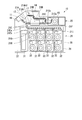
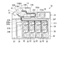
- the lower unit 26 includes a housing 35, a unit main body 36, and a lid body 37.
- the housing 3 opens forward and has a rectangular parallelepiped box shape.
- the unit main body 36 has eight storages 32 and is disposed in the housing 35.
- the lid 37 opens and closes the front opening of the housing 35.
- the front cassette 31 is detachably attached to the unit main body 36.
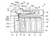
- the lid 37 is rotatable about a lid rotating shaft 41 extending vertically at one end in the left-right direction of the front portion in the closed state shown by a solid line in FIG. 2, specifically, at the corner position of the right end.
- the casing 35 is connected to one end in the left-right direction, specifically, the front end edge at the right end. That is, the lid body 37 is coupled to the housing 35 by a hinge and rotates horizontally around the vertical axis.
- the lid 37 is opened to the right.
- the entire front opening of the housing 35 enters the inside thereof and is closed. Further, when the lid 37 is changed from the closed state indicated by the solid line in FIG. 2 to the open state indicated by the two-dot chain line in FIG. Rotate to the right and retract from the front range of the front opening.
- the unit main body 36 is supported on the left and right inner surfaces of the casing 35 via slide rails (not shown), and is connected to the casing 35 so as to be slidable in the horizontal direction.
- a closed state stored state
- a space is formed between the unit main body 36 and the front end of the housing 35 in which the lid 37 can be inserted.
- the unit main body 36 protrudes forward from the front opening when pulled out from the casing 35, and as a whole is pulled out from the casing 35 as shown by a two-dot chain line in FIG. .
- the unit main body 36 can be pulled out, that is, can be opened only when the lid 37 is in an open state indicated by a two-dot chain line in FIG. That is, the unit main body 36 can be pulled out forward from the housing 35 after the lid 37 is rotated about the lid rotation shaft 41 to be in the open state.
- the lid body 37 is not provided with a configuration related to bill processing. That is, the lid 37 is a structure that functions only as a lid that opens and closes the front opening of the housing 35.
- the housing 35 and the lid body 37 function as a safe for ensuring the security of the front cassette 31 and the eight storage boxes 32.
- the banknote identified by the identification unit 17 as being acceptable is transported to the temporary storage unit 18 by the front path unit 21Ca and the rear path unit 21Cb of the linear transport path 21C, and temporarily stored in the temporary storage unit 18 (FIG. 3A). (See thick solid line).
- the banknote identified as unacceptable by the identification unit 17 is conveyed from the front-side path unit 21Ca of the straight conveyance path 21C to the dispensing unit 21D by the dispensing conveyance path 21D (see the thick solid line to the thick broken line in FIG. 3A).
- the input unit 11 separates and feeds out banknotes stacked in the thickness direction. For this reason, there is a possibility that poor conveyance such as double feeding and skew feeding may occur when the feeding unit 11 is fed out. Such a defectively conveyed banknote is recognized as being unacceptable by the identification unit 17 and is conveyed to the dispensing unit 12.
- the amount of the banknotes temporarily stored in the temporary storage unit 18 based on the identification result of the identification unit 17
- the operation display unit 14 displays the information.
- This money amount information includes the number of bills and the total amount. The bills conveyed to the dispensing unit 12 can be taken out to the outside.
- the banknotes are distributed to the corresponding storage bins 32 of the eight storage bins 32 by the storage conveyance path 21F and the appropriate conveyance path among the branch conveyance paths 21G to 21I.
- Corresponding storages 32 of the eight storages 32 store the sorted banknotes.
- the temporary storage unit 18 is a wound storage type. For this reason, there is basically no conveyance failure such as double feeding or skew feeding when the temporary storage unit 18 is fed out. Therefore, basically, the banknotes fed out by the temporary storage unit 18 are not determined to be unacceptable by the identification unit 17.
- the banknote which the identification part 17 identified as a banknote of a designated denomination is conveyed from the front side path part 21Ca of the linear conveyance path 21C by the rear side path part 21Cb to the temporary storage part 18, and the temporary storage part 18 is temporarily stored. (See the thick solid line in FIG. 5A).
- a banknote (including a poorly transported banknote) identified by the identifying unit 17 as a banknote other than the designated denomination is transported to the dispensing unit 12 by the withdrawal transporting path 21D from the front path part 21Ca of the linear transporting path 21C. (See thick solid line to thick broken line in FIG. 5A).
- the bills conveyed to the dispensing unit 12 can be taken out to the outside.
- the operation display unit 14 displays money amount information such as the denomination (that is, the set denomination), the number of sheets, and the total amount of the banknotes conveyed to the dispensing unit 12.
- the bills conveyed to the dispensing unit 12 can be taken out to the outside. Only the banknote which the identification part 17 identified as the banknote of a designated denomination in the front
- the fed banknotes are transferred from an appropriate conveyance path among the branch conveyance paths 21G to 21I, the storage conveyance path 21F, the upper conveyance section 21Ea of the vertical conveyance path 21E, the rear configuration section 21Ab2 of the deposit conveyance path 21A, and the identification section.
- the 17 internal conveyance paths 21B, the front-side feeding section 21Ca and the withdrawal conveyance path 21D of the straight conveyance path 21C are conveyed to the dispensing section 12.
- All the storage boxes 32 are of a winding type. For this reason, basically, there is no conveyance failure such as double feeding and skew feeding when the container 32 is fed out. Therefore, basically, the banknotes fed out by the storage 32 are not determined to be unpaid by the identification unit 17.
- the bills conveyed to the dispensing unit 12 can be taken out to the outside.
- the banknotes are then conveyed through the subsequent route of the withdrawal and withdrawal process indicated by the thick line in FIG. 7B.
- the temporary storage unit 18 pays out the banknotes other than the withdrawal target that have been temporarily stored, the straight conveyance path 21C, the internal conveyance path 21B of the identification unit 17, the rear side configuration part 21Ab2 of the deposit conveyance path 21A, and the vertical conveyance path.
- the upper feed path 21Ea and the storage transport path 21F of 21E are transported.
- the identification unit 17 identifies the banknote.
- the appropriate conveyance path among the storage conveyance path 21F and the branch conveyance paths 21G to 21I sorts the banknotes into the corresponding storage bins 32 of the eight storage bins 32.
- Corresponding storages 32 of the eight storages 32 store the sorted banknotes.
- the banknote is conveyed along the forward route of the scrutiny process indicated by a thick line in FIG. 8A. That is, one of the eight storage bins 32 to be scrutinized pays out bills. Further, the fed banknotes are transferred to the corresponding conveyance path among the branch conveyance paths 21G to 21I, the storage conveyance path 21F, the upper conveyance path 21Ea of the vertical conveyance path 21E, the rear component 21Ab2 of the deposit conveyance path 21A, and the identification unit.
- the 17 internal conveyance paths 21 ⁇ / b> B and the straight conveyance path 21 ⁇ / b> C are conveyed to the temporary storage unit 18.
- the temporary storage unit 18 temporarily stores the banknote. In this way, all banknotes stored in one storage 32 to be examined are transported to the temporary storage unit 18.
- the banknotes are conveyed along the return route of the scrutiny process indicated by the bold line in FIG. 8B. That is, the temporary storage unit 18 pays out the banknotes temporarily stored. Further, the bill is conveyed by the straight conveyance path 21C, the internal conveyance path 21B of the identification unit 17, the rear side configuration part 21Ab2 of the deposit conveyance path 21A, the upper transmission path part 21Ea of the vertical conveyance path 21E, and the storage conveyance path 21F. During the conveyance on the internal conveyance path 21 ⁇ / b> B, the identification unit 17 identifies the banknote.
- the storage transport path 21F and the appropriate transport path among the branch transport paths 21G to 21I transport the banknotes to one of the eight storages 32 to be examined, and this storage 32 Stores banknotes. From the identification result of the identification unit 17 at this time, the number information of the banknotes stored in the storage 32 to be examined, that is, the amount information is determined.
- the banknotes are transported along the upstream route of the cassette replenishment process indicated by a thick line in FIG. 9A. That is, the front cassette 31 pays out the banknotes, and the banknotes that have been fed out are sent to the upper and lower transfer paths 21E, the rear side configuration part 21Ab2 of the deposit transfer path 21A, the internal transfer path 21B of the identification part 17 and the front path part of the straight transfer path 21C. 21Ca carries.
- the identification unit 17 identifies the banknote.
- the banknote identified as being acceptable is conveyed to the temporary storage unit 18 by the rear path unit 21Cb of the straight conveyance path 21C and temporarily stored by the temporary storage unit 18 (see the thick solid line in FIG. 9A).
- the front cassette 31 is an integrated storage type. For this reason, there is a possibility of poor conveyance such as double feeding and skew feeding of banknotes fed out from the front cassette 31.
- the withdrawal transport path 21D is transported from the front path section 21Ca of the straight transport path 21C to the dispensing section 12 (see the thick solid line to the thick broken line in FIG. 9A). ).
- the bills conveyed to the dispensing unit 12 can be taken out to the outside.
- the storage capacity of the front cassette 31 is larger than the storage capacity of the temporary storage unit 18. For this reason, the temporary storage part 18 may become full before the front cassette 31 becomes empty.
- the banknotes are transported by a subsequent route of the cassette replenishment process indicated by a thick line in FIG. 9B. That is, the temporary storage part 18 pays out the temporarily stored banknotes, and the straight conveyance path 21C, the internal conveyance path 21B of the identification part 17, the rear side configuration part 21Ab2 of the deposit conveyance path 21A, and the upper conveyance path of the vertical conveyance path 21E.
- the part 21Ea and the storage conveyance path 21F convey.
- the identification unit 17 identifies the banknote. Based on the identification result, the appropriate conveyance path among the storage conveyance path 21F and the branch conveyance paths 21G to 21I sorts the banknotes into the corresponding storage bins 32 of the eight storage bins 32. The corresponding storage bins 32 of the eight storage bins 32 store the sorted banknotes.
- the banknote is transported through the upstream route of the deposit port replenishment process indicated by a thick line in FIG. 10A. That is, the insertion unit 11 separates and feeds banknotes one by one. Further, the fed banknotes are transported by the deposit transport path 21A, the internal transport path 21B of the identification unit 17 and the front path section 21Ca of the straight transport path 21C. During the conveyance on the internal conveyance path 21 ⁇ / b> B, the identification unit 17 identifies the banknote.
- the banknotes identified by the identifying unit 17 as being acceptable are transported to the temporary storage unit 18 by the front path unit 21Ca and the rear path unit 21Cb of the linear transport path 21C, and temporarily stored by the temporary storage unit 18 (FIG. 10A). (See bold line).
- banknotes (including badly transported banknotes) identified as unacceptable by the identification unit 17 are transported from the front side path part 21Ca of the straight conveyance path 21C to the withdrawal part 12 by the withdrawal part 12 (thick solid line in FIG. 10A). To thick dashed line).
- the bills conveyed to the dispensing unit 12 can be taken out to the outside.
- the banknotes inserted into the input unit 11 are conveyed to either the temporary storage unit 18 or the payout unit 12, the banknotes are conveyed through a subsequent route of the deposit port replenishment process indicated by a thick line in FIG. 10B. That is, the temporary storage unit 18 pays out the banknotes temporarily stored.
- the bills are conveyed by the straight conveyance path 21C, the internal conveyance path 21B of the identification unit 17, the rear side configuration part 21Ab2 of the deposit conveyance path 21A, the upper transmission path part 21Ea of the vertical conveyance path 21E, and the storage conveyance path 21F.
- the identification unit 17 identifies the banknote.
- the appropriate transport path among the storage transport path 21F and the branch transport paths 21G to 21I distributes the banknotes to the corresponding storage 3 of the eight storages 32.
- Corresponding storages 32 of the eight storages 32 store the sorted banknotes. In this way, the bills inserted into the insertion unit 11 are sorted and stored in the corresponding storage bins 32 of the eight storage bins 32.
- the banknotes are transported by a subsequent route of the collection process indicated by a thick line in FIG. That is, the temporary storage unit 18 pays out the banknotes temporarily stored. Further, the straight conveyance path 21C, the internal conveyance path 21B of the identification unit 17, the rear side configuration portion 21Ab2 of the deposit conveyance path 21A, and the vertical conveyance path 21E are conveyed to the front cassette 31, and the front cassette 31 is accommodated.
- Such processing is performed on the storage bins 32 that are designated to be collected among the plurality of storage bins 32 (the entire storage bins 32 may be specified). Thereafter, the lid 37 is opened, the unit main body 36 is pulled out from the housing 35, and the front cassette 31 is removed from the unit main body 36.
- the identification part 17 and the temporary storage part 18 are connected by the straight linear conveyance path 21C, and after a banknote is identified by the identification part 17, it is a temporary storage part by the linear conveyance path 21C. 18 is conveyed. For this reason, a banknote is not conveyed in the state curved from the identification part 17 to the temporary storage part 18. FIG. Therefore, the occurrence of jam can be suppressed. Further, when the banknote is transported from the temporary storage unit 18 to the identification unit 17, the banknote is transported by the straight transport path 21 ⁇ / b> C. For this reason, the bill is not conveyed from the temporary storage unit 18 to the identification unit 17 in a curved state. Therefore, the occurrence of jam can be suppressed.
- the straight conveyance path 21C extends in the horizontal direction and connects the identification unit 17 and the temporary storage unit 18 in which the positions in the height direction are overlapped (matched). For this reason, the length in the height direction of the paper sheet processing apparatus 10 can be shortened, and the entire size of the paper sheet processing apparatus 10 can be reduced.
- the insertion part 11 which feeds the inserted banknote toward the identification part 17, the identification part 17 which identifies the banknote fed out from the insertion part 11, and the banknote identified by the identification part 17 are conveyed by the straight conveyance path 21C.
- the temporary storage unit 18 is arranged in this order from the front side of the paper sheet processing apparatus 10 toward the rear side of the paper sheet processing apparatus 10. For this reason, the input part 11 is not laminated
- the paper sheet processing apparatus 10 can suppress the occurrence of banknote jam.
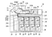
- the paper sheet processing apparatus according to the second embodiment of the present invention will be described below with reference mainly to FIGS. 12 to 16B, focusing on the differences from the first embodiment.
- three storage bins 51 are replaced with a total of six storage bins 32 arranged in the upper and lower rows of the rear three rows. Is provided.
- the height of the storage 51 is equal to the height of the two storages 32.
- the three storages 51 overlap (match) the two-stage storages 32 arranged one above the other in the height direction.
- Each of the three storage boxes 51 can take in and store banknotes one by one, and can feed out banknotes stored one by one.
- Each of the three storages 51 is a stacked storage type in which banknotes are received from the upper part and stacked and stored in a horizontal state from the bottom to the top, and the stored banknotes are fed out from the upper end banknotes. For this reason, when a banknote is paid out from the three storages 51, there is a possibility that the fed banknote has a conveyance failure such as double feeding or skew feeding. In the second embodiment, the transport route in that case is different from that of the first embodiment.
- the storage 51 of the accumulation storage type has significantly higher banknote storage efficiency than the winding storage type such as the temporary storage unit 18 and the storage 32.
- the storage capacities of the three storages 51 are equal to each other.
- the storage capacity of each storage 51 is the same as that of the front cassette 31.
- two storage boxes 32 are set as denomination mixed storage boxes, and three storage boxes 51 are set as single denomination storage boxes.
- Setting of the single denomination storage and the denomination mixed storage is possible arbitrarily, but the three storages 51 are preferably set as the single denomination storage.
- the bill inserted into the insertion unit 11 is identified by the identification unit 17, and the banknote identified as acceptable is temporarily stored in the temporary storage unit 18. (See the thick solid line in FIG. 3A), and the banknotes (including badly conveyed banknotes) identified as unacceptable are transported to the dispensing unit 12 (see the thick solid lines from the thick solid lines in FIG. 3A).
- the banknote temporarily stored in the temporary storage unit 18 is identified by the identification unit 17 in the same route as the storage processing route indicated by the thick line in FIG. 3B of the first embodiment, and the upper and lower units are stored based on the result. It stores in the corresponding one of the storage 32 and the three storages 51.
- ⁇ Organization counting process '' 5A of the first embodiment is the same route as the pre-stage route of the organizing and counting process indicated by the bold line, the banknote inserted into the input unit 11 is identified by the identification unit 17, and the banknote identified as the designated denomination is temporarily stored. 18 is temporarily stored (refer to the thick solid line in FIG. 5A), and the banknotes (including badly conveyed banknotes) identified as other than the designated denomination are transported to the dispensing unit 12 (refer to the thick solid line from the thick solid line in FIG. 5A). Next, the banknote temporarily stored in the temporary storage unit 18 is transported to the dispensing unit 12 through the same route as the subsequent route of the counting and counting process indicated by the thick line in FIG. 5B of the first embodiment, and temporarily stored in the previous route. The identification result of the identification unit 17 for the banknote temporarily stored in the unit 18 is displayed on the operation display unit 14.
- the 17 internal conveyance path 21B and the front side path part 21Ca of the linear conveyance path 21C convey.
- the banknotes identified by the identification unit 17 during conveyance on the internal conveyance path 21B and determined to be able to be dispensed by the identification unit 17 are conveyed to the dispensing unit 12 by the dispensing conveyance path 21D (see the thick solid line in FIG. 13). .
- the three storages 51 are of a collective storage type, there is a possibility that poor conveyance such as double feeding and skew feeding may occur when banknotes are fed from the storage 51.
- Such an unacceptable banknote is determined to be unacceptable by the identification unit 17, the rear-side channel 21 ⁇ / b> Cb of the linear conveyance path 21 ⁇ / b> C is conveyed to the temporary storage unit 18, and is temporarily stored by the temporary storage unit 18 (FIG. (See 13 thick solid line to thick broken line).
- the two storages 32 of the winding storage type are set as denomination mixed storages. For this reason, the storage 32 may pay out banknotes other than the withdrawal target denomination at the time of paying out.
- the banknotes identified by the identification unit 17 as being other than such withdrawal target denominations are also transported to the temporary storage unit 18 by the rear path unit 21Cb of the linear transport path 21C and temporarily stored by the temporary storage unit 18. (See thick solid line to thick broken line in FIG. 13). Thereafter, when all the banknotes to be withdrawn are conveyed to the dispensing unit 12, the banknotes temporarily stored in the temporary storage unit 18 are identified by the identification unit 17. Based on the identification result, the banknote is stored in the corresponding storage of the two storages 32 and the three storages 51. For example, the normal transport banknote is stored in the storage 51 that is set to store the denomination corresponding to the denomination of the banknote among the three storages 51. A conveyance failure banknote is accommodated in the appropriate storage 32 of the two storages 32 of denomination mixing.
- the two wrapping storage type storages 32 arranged one above the other are not subject to scrutiny because there is a possibility of storing poorly conveyed banknotes.
- Three storages 51 of the integrated storage type set in the single denomination storage are subject to scrutiny.
- a banknote is conveyed from the storage object 51 of the inspection object 51 in the storage object 51 in the upstream route of the forward process of the inspection process indicated by a thick line in FIG. 14A. That is, one of the scrutinized objects in the storage 51 pays out banknotes.
- an appropriate branch conveyance path among the branch conveyance paths 21H and 21I is configured to store the fed banknotes in the storage conveyance path 21F, the upper conveyance path 21Ea of the upper and lower conveyance paths 21E, and the rear component 21Ab2 of the deposit conveyance path 21A.
- the internal conveyance path 21B and the straight conveyance path 21C of the identification unit 17 are conveyed to the temporary storage unit 18, and the temporary storage unit 18 temporarily stores them.
- Such poorly conveyed banknotes are also temporarily stored in the temporary storage unit 18 as they are.
- the banknotes are transported in the subsequent route of the scrutinization process indicated by a thick line in FIG. 14B. That is, the temporary storage unit 18 pays out the banknotes temporarily stored. Further, the bill is conveyed by the straight conveyance path 21C, the internal conveyance path 21B of the identification unit 17, the rear side configuration part 21Ab2 of the deposit conveyance path 21A, and the upper path part 21Ea of the vertical conveyance path 21E. During the conveyance on the internal conveyance path 21 ⁇ / b> B, the identification unit 17 identifies the banknote.
- a deed type banknote to be examined is transported to the front cassette 31 by the lower path 21Eb of the upper and lower transport path 21E, and is stored in the front cassette 31 (see a thick solid line in FIG. 14B).
- Banknotes of denominations (including banknotes with poor conveyance) other than those to be scrutinized are transported to a storage 32 set as a denomination mixed storage by the storage transport path 21F and the branch transport path 21G, and stored in the storage 32. (See thick solid line to thick broken line in FIG. 14B).
- the banknotes are transported in the upstream route of the return process of the scrutiny process indicated by the thick line in FIG. 15A. That is, the front cassette 31 pays out banknotes. Further, the fed banknotes are transported to the temporary storage unit 18 by the upper and lower transport path 21E, the rear side configuration part 21Ab2 of the deposit transport path 21A, the internal transport path 21B and the straight transport path 21C of the identification unit 17, and the temporary storage part 18 Temporarily store. At this time, there is also a banknote that becomes a poorly transported banknote when it is fed out from the stacking type forward cassette 31. Such poorly conveyed banknotes are also temporarily stored in the temporary storage unit 18 as they are.
- the banknotes are transported in the subsequent route of the return processing of the scrutiny processing indicated by the thick line in FIG. 15B. That is, the temporary storage part 18 pays out the temporarily stored banknotes, and the straight conveyance path 21C, the internal conveyance path 21B of the identification part 17, the rear side configuration part 21Ab2 of the deposit conveyance path 21A, and the upper conveyance path of the vertical conveyance path 21E.
- the part 21Ea and the storage conveyance path 21F convey.
- the identification unit 17 identifies the banknote.
- the banknote to be scrutinized is transported to one of the three storages 51 by the appropriate transport path among the storage transport path 21F and the branch transport paths 21H and 21I.
- the storage 51 stores (refer to the thick solid line in FIG. 15B).
- Banknotes of denominations (including banknotes with poor conveyance) other than those to be scrutinized are transported to a storage 32 set as a denomination mixed storage by the storage transport path 21F and the branch transport path 21G, and stored in the storage 32. (See thick solid line to thick broken line in FIG. 15B).
- the return process of the above scrutiny process is repeated as appropriate until the front cassette 31 is empty. Then, from the identification result of the identification unit 17 in the subsequent route at the time of the return path processing of the scrutiny processing, the number information of the banknotes stored in the scrutiny storage 51, that is, the amount information is determined.
- the banknote fed out from the front cassette 31 is identified by the identification unit 17 in the same route as the cassette replenishment process route indicated by a bold line in FIG. 9A, and is identified as acceptable based on the identification result.
- the stored banknotes are temporarily stored in the temporary storage unit 18 (see the thick solid line in FIG. 9A), while the banknotes identified as unacceptable by the identification unit 17 are conveyed to the dispensing unit 12 (see the thick broken line from the thick solid line in FIG. 9A).
- the banknotes are transported through a route similar to the subsequent route of the cassette replenishment process indicated by the thick line in FIG. 9B of the first embodiment. That is, the banknote temporarily stored in the temporary storage unit 18 is identified by the identification unit 17, and based on the identification result, the corresponding storage 51 of the three storages 51 set as the single denomination storage. Sort banknotes. The above processing is repeated as appropriate until the front cassette 31 is empty.
- a bill inserted into the insertion unit 11 is identified by the identification unit 17 in the same route as the previous route of the deposit port replenishment process indicated by a thick line in FIG. 10A of the first embodiment.
- the banknote identified by the identification unit 17 as being acceptable is temporarily stored in the temporary storage unit 18 (see the thick solid line in FIG. 10A), while the banknote identified by the identification unit 17 as unacceptable is transported to the dispensing unit 12 (in FIG. 10A). (See thick solid line to thick broken line).
- the banknote temporarily stored in the temporary storage unit 18 is identified by the identification unit 17 in the same route as the subsequent route of the deposit port replenishment process indicated by the thick line in FIG. 10B of the first embodiment. Based on the identification result, the banknotes are distributed to the corresponding one of the two storage boxes 32 and the three storage boxes 51.
- a banknote is conveyed by the front
- the banknotes are transported through the subsequent route of the collection process indicated by the thick line in FIG. 16B. That is, the temporary storage unit 18 pays out the banknotes temporarily stored. Furthermore, the straight conveyance path 21C, the internal conveyance path 21B of the identification unit 17, the rear side configuration part 21Ab2 of the deposit conveyance path 21A, and the upper path part 21Ea of the vertical conveyance path 21E are conveyed. During the conveyance on the internal conveyance path 21 ⁇ / b> B, the identification unit 17 identifies the banknote.
- the banknotes to be collected are transported to the front cassette 31 by the lower path portion 21Eb of the vertical transport path 21E and stored in the front cassette 31 (see the thick solid line in FIG. 16B).
- Banknotes other than those to be collected are transported to the storage 32 where the storage transport path 21F and the branch transport path 21G are set as denomination mixed storages, and the storage 32 stores them (FIG. 16B). (See thick solid line to thick broken line).
- the above processing is repeated as appropriate until the collection target storage 51 is empty. Thereafter, the lid 37 is opened, the unit main body 36 is pulled out from the housing 35, and the front cassette 31 is removed from the unit main body 36. Depending on the total amount of banknotes in the plurality of storages 51, the banknotes in these storages 51 can be stored in the front cassette 31 and collected at a time.
- the banknotes stored in the storage 32 set as the denomination mixed storage are later transported to the dispensing unit 12 through the same route as the withdrawal process and taken out.
- a paper sheet processing apparatus includes an identification unit that identifies paper sheets, a temporary storage unit that temporarily stores the identified paper sheets, the identification unit, and the temporary storage unit.
- a straight conveyance path that connects, extends in a straight line, and conveys paper sheets identified by the identification unit to the temporary storage unit.
- the position of the identification unit in the height direction is aligned with the position of the temporary storage unit in the height direction, and the linear conveyance path extends in the lateral direction.
- the identification unit and the temporary storage unit which are aligned in the height direction, are connected to each other by the straight conveyance path that extends in the lateral direction. For this reason, the length in the height direction of the apparatus can be shortened, and the entire apparatus can be reduced in size.
- the paper sheet processing apparatus further includes an input unit that inputs paper sheets and feeds the input paper sheets toward the identification unit, and the identification unit identifies the input paper sheets
- the straight conveyance path conveys the inserted and identified paper sheets to the temporary storage unit, and the input unit, the identification unit, and the temporary storage unit are arranged in front of the paper sheet processing apparatus. To the rear of the sheet processing apparatus, the input unit, the identification unit, and the temporary storage unit are arranged in this order.
- the input unit that feeds the input paper sheet toward the identification unit, the identification unit that identifies the paper sheet fed from the input unit, and the paper that has been identified by the identification unit A temporary storage unit in which leaves are conveyed by a straight conveyance path is arranged in this order from the front of the apparatus. For this reason, an insertion part is not laminated
- the paper sheet is a banknote.
- the paper sheet processing apparatus since the paper sheet to be processed is a banknote, it is possible to suppress the occurrence of banknote jam.
- the present invention may be applied to a paper sheet processing apparatus.
Landscapes
- Physics & Mathematics (AREA)
- General Physics & Mathematics (AREA)
- Engineering & Computer Science (AREA)
- Mechanical Engineering (AREA)
- Separation, Sorting, Adjustment, Or Bending Of Sheets To Be Conveyed (AREA)
- Sorting Of Articles (AREA)
Abstract
紙葉類処理装置は、紙葉類を識別する識別部と、前記識別された紙葉類を一時貯留する一時貯留部と、前記識別部と前記一時貯留部とを接続し、一直線に延び、前記識別部によって識別された紙葉類を前記一時貯留部に搬送する直線搬送路と、を備える。
Description
本発明は、紙葉類処理装置に関する。
本願は、2015年7月17日に出願された特願2015-142881号に基づき優先権を主張し、その内容をここに援用する。
本願は、2015年7月17日に出願された特願2015-142881号に基づき優先権を主張し、その内容をここに援用する。
従来から、入金部から入金されて識別部によって識別された紙幣等を一時保留部に一時的に保留させて、各種処理が終了した後に、紙幣を一時保留部から収納部等に搬送して収納する紙幣処理装置が知られている(例えば、特許文献1参照。)。
しかしながら、特許文献1のような従来の紙幣処理装置は、例えば、装置の前方に入金部が配置され、この入金部の下に一時保留部が配置され、装置の後方に識別部が配置されている。更に、入金部と識別部と一時保留部とは、複数の曲がり部を有する環状搬送路を介して接続されている。
そして、従来の紙幣処理装置では、装置の後方に識別部が配置され、装置の前方に一時保留部が配置され、識別部と一時保留部とが環状搬送路を介して接続されているので、識別部によって識別された紙幣は、環状搬送路を介して、一度装置の後方へ搬送された後に装置の前方に搬送される等、一時保留部に略U字状に迂回して湾曲搬送される。このため、識別部から一時保留部までの搬送距離が長く、更に、搬送路中に曲がり部や分岐部等を多数通過するので、ジャムが発生する可能性が高い。
したがって、本発明は、ジャムの発生を抑制することができる紙葉類処理装置の提供を目的とする。
上記目的を達成するために、本発明の実施態様に係る紙葉類処理装置は、紙葉類を識別する識別部と、前記識別された紙葉類を一時貯留する一時貯留部と、前記識別部と前記一時貯留部とを接続し、一直線に延び、前記識別部によって識別された紙葉類を前記一時貯留部に搬送する直線搬送路と、を備える。
本発明によれば、識別部と一時貯留部とが一直線に延びる直線搬送路で接続されており、識別部によって識別された紙葉類が直線搬送路で一時貯留部に搬送される。このため、識別部から一時貯留部に紙葉類が湾曲して搬送されることがない。したがって、ジャムの発生を抑制することができる。
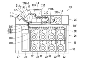
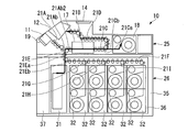
本発明の第1実施形態に係る紙葉類処理装置を図1~図11Bを参照して以下に説明する。第1実施形態に係る紙葉類処理装置10は、紙葉類としての紙幣を処理する。紙葉類処理装置10、紙幣以外の紙葉類を処理しても良い。紙葉類処理装置10は、外部から投入された紙幣を内部に収納する入金処理と、内部に収納されている紙幣を外部に取り出し可能に出金する出金処理とが可能な紙幣入出金装置である。以下の説明において、「前」は操作者側を示し、「後」は操作者とは反対側を示し、「左」は操作者から見て左を示し、「右」は操作者から見て右を示す。
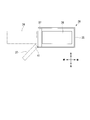
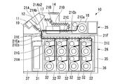
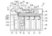
図1に示すように、紙葉類処理装置10は、前面側の上部に設けられた、入金用の紙幣が外部から投入される投入部11を有する。紙葉類処理装置10は、この投入部11の上方かつ後方に設けられた払出部12を有する。払出部12に、入金用の紙幣のうち受け入れ不可なリジェクト紙幣が内部から繰り出されるとともに出金用の紙幣が内部から繰り出される。払出部12は、これらの紙幣を外部に取り出し可能とする。
投入部11と払出部12とは、高さ方向(垂直方向、紙葉類処理装置10の高さ方向)の位置を重ね合わせて(合わせて)設けられており、前後方向の位置も重ね合わせて(合わせて)設けられている。紙葉類処理装置10は、上面の払出部12の後方に設けられた操作表示部14を有する。操作表示部14は、タッチパネル式であり、操作者の操作入力を受け付けるとともに操作者に対し表示を行う。
投入部11と払出部12とは、高さ方向(垂直方向、紙葉類処理装置10の高さ方向)の位置を重ね合わせて(合わせて)設けられており、前後方向の位置も重ね合わせて(合わせて)設けられている。紙葉類処理装置10は、上面の払出部12の後方に設けられた操作表示部14を有する。操作表示部14は、タッチパネル式であり、操作者の操作入力を受け付けるとともに操作者に対し表示を行う。
紙葉類処理装置10は、投入部11の後方に設けられた識別部17を有する。識別部17は、紙幣を識別し、投入部11と高さ方向の位置を重ね合わせて(合わせて)設けられている。紙葉類処理装置10は、この識別部17の後方に設けられた一時貯留部18を有する。一時貯留部18は、識別部17により識別された紙幣を一時貯留し、投入部11および識別部17と高さ方向の位置を重ね合わせて(合わせて)設けられている。投入部11の下部と識別部17の上部とが高さ方向の位置を重ね合わせて(合わせて)いる。投入部11の上部と識別部17の下部とは高さ方向の位置をずらしている。識別部17の全体と一時貯留部18の中間部から下部までとが高さ方向の位置を重ね合わせて(合わせて)いる。一時貯留部18の上部は識別部17に対し高さ方向の位置をずらしている。
一時貯留部18の上部が払出部12の下部と高さ方向の位置を重ね合わせて(合わせて)いる。
投入部11と識別部17と一時貯留部18とが、紙葉類処理装置10の前方から後方に向けて、投入部11、識別部17、一時貯留部18の順に配置されている。投入部11と識別部17とは前後方向の位置を完全にずらしている。識別部17と一時貯留部18とは前後方向(水平方向、紙葉類処理装置10の前後方向、紙葉類処理装置10の高さ方向と直交する方向)の位置を完全にずらしている。
一時貯留部18の上部が払出部12の下部と高さ方向の位置を重ね合わせて(合わせて)いる。
投入部11と識別部17と一時貯留部18とが、紙葉類処理装置10の前方から後方に向けて、投入部11、識別部17、一時貯留部18の順に配置されている。投入部11と識別部17とは前後方向の位置を完全にずらしている。識別部17と一時貯留部18とは前後方向(水平方向、紙葉類処理装置10の前後方向、紙葉類処理装置10の高さ方向と直交する方向)の位置を完全にずらしている。
投入部11には、載置板19が後下がりの姿勢で設けられている。この載置板19は、投入部11内で後上がりの方向に上昇し、また、前下がりの方向に下降する動作を行う。下降動作後の状態にある載置板19上に集積状態の紙幣が外部から載置される。その結果、載置板19上に載置された紙幣は後上がりの方向に集積された状態となる。載置板19は上昇して集積状態の紙幣を後上がりの方向に搬送し、集積状態の紙幣を集積方向の上端の紙幣から一枚ずつ紙葉類処理装置10の内部に繰り出す。
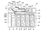
投入部11の後端部に、投入部11から繰り出された紙幣を搬送する入金搬送路21Aが接続されている。入金搬送路21Aは、投入部11から後下がりに延出する傾斜送路部21Aaと、傾斜送路部21Aaの後端から水平後方に延出する水平送路部21Abとを有している。入金搬送路21Aは、水平送路部21Abの後端部において識別部17に接続されている。
識別部17は、入金搬送路21Aの水平送路部21Abと同一直線上に配置されて水平送路部21Abの後端部から水平後方に延出する内部搬送路21Bを有している。内部搬送路21Bは、水平送路部21Abから引き続き後方に紙幣を搬送する。識別部17は、内部搬送路21Bで搬送中の紙幣の真偽、正損、金種、重送、斜行等を識別する。
識別部17の内部搬送路21Bの後端部からは水平後方に直線搬送路21Cが延出している。この直線搬送路21Cの後端部が一時貯留部18に接続されている。直線搬送路21Cは、内部搬送路21Bから引き続き後方に紙幣を搬送する。入金搬送路21Aの水平送路部21Abと内部搬送路21Bと直線搬送路21Cとは同一直線上で一直線に並んでいる。識別部17と一時貯留部18とが一直線の直線搬送路21Cで接続されている。すなわち、直線搬送路は、識別部17と一時貯留部18と接続し、一直線に延びる。言い換えると、直線搬送路21Cは、識別部17と接続する先端部(第1端)と一時貯留部18と接続する後端部(第2端)とを有し、後端部から先端部まで水平に一直線に延びる。例えば、投入部11に投入された紙幣が、投入部11から入金搬送路21Aで識別部17に向けて搬送され、識別部17で識別後に直線搬送路21Cで一時貯留部18に搬送される。すなわち、直線搬送路21Cは、識別部17によって識別された紙幣の垂直方向における位置を維持したまま、その紙幣を、識別部17から一時貯留部18まで水平に搬送する。言い換えると、直線搬送路21Cは、識別部17によって識別された紙幣が湾曲していない状態を維持したまま、その紙幣を、識別部17から一時貯留部18まで搬送する。上記のように識別部17と一時貯留部18とは高さ方向の位置を重ね合わせて(合わせて)いる。すなわち、垂直方向における識別部17の位置が垂直方向における一時貯留部18の位置と合わされている。直線搬送路21Cが横方向、具体的には水平方向に延在して、識別部17と一時貯留部18とを結んでいる。
一時貯留部18は、紙幣を一時貯留させ、直線搬送路21Cで搬送されてきた紙幣を一枚ずつ取り込んで収納し、収納している紙幣を一枚ずつ直線搬送路21Cに繰り出す。この一時貯留部18は、紙幣をテープとともにドラムに巻き付けて収納し紙幣をテープとともにドラムから解いて繰り出す巻付収納タイプである。
直線搬送路21Cの中間位置(途中位置)からは出金搬送路21Dが上方に分岐している。この出金搬送路21Dが払出部12に接続されている。出金搬送路21Dが分岐することによって、直線搬送路21Cは、出金搬送路21Dの分岐位置より前側の前側送路部21Caと、出金搬送路21Dの分岐位置より後側の後側送路部21Cbとに分けられる。前側送路部21Caと後側送路部21Cbとの間は紙幣の行き来が可能である。前側送路部21Caと出金搬送路21Dとの間は前側送路部21Caから出金搬送路21Dへの紙幣の搬送が可能である。後側送路部21Cbと出金搬送路21Dとの間は後側送路部21Cbから出金搬送路21Dへの紙幣の搬送が可能である。
出金搬送路21Dは、直線搬送路21Cで搬送されてきた紙幣を払出部12に搬送する。出金搬送路21Dは、鉛直送路部21Daと、水平送路部21Dbと、鉛直送路部21Dcと、水平送路部21Ddとを有している。鉛直送路部21Daは、直線搬送路21Cの中間位置(途中位置)から鉛直上方に延出する。水平送路部21Dbは、鉛直送路部21Daの上端部から水平前方に延出する。鉛直送路部21Dcは、水平送路部21Dbの前端部から鉛直上方に延出する。水平送路部21Ddは、鉛直送路部21Dcの上端部から水平前方に延出して払出部12に繋がる。
払出部12は、出金搬送路21Dの水平送路部21Ddから繰り出された紙幣を前側かつ下側から後側かつ上側に斜めに集積させる。払出部12に集積された紙幣は、払出部12から外部に取り出される。出金搬送路21Dは、直線搬送路21Cの途中から上方に分岐した搬送路である。よって、出金搬送路21Dは、例えば、一時貯留部18から直線搬送路21Cに繰り出された紙幣を直線搬送路21Cの途中から上方に搬送して払出部12に放出する。
上部ユニット25は、紙葉類処理装置10の上部を構成する。上部ユニット25には、投入部11、払出部12、操作表示部14、内部搬送路21Bを含む識別部17、一時貯留部18、入金搬送路21A、直線搬送路21Cおよび出金搬送路21Dを有する。
下部ユニット26は、上部ユニット25の下側に設けられ、紙葉類処理装置10の高さ方向の中間部から下部を構成する。下部ユニット26は、前部位置に設けられた前方カセット31と、前方カセット31の後方に設けられた収納庫32とを有する。収納庫32は、合計8台である。収納庫32は、上下方向に2段、かつ、前後方向に4列に配置されている。8台の収納庫32のうち、上段の4台は高さ方向の位置を一致させている。台の収納庫32のうち、下段の4台も高さ方向の位置を一致させている。前方カセット31の高さは、収納庫32の2台分の高さと同等である。前方カセット31は、上下に並べられた2段の収納庫32と高さ方向の位置を重ね合わせて(合わせて)いる。
入金搬送路21Aの水平送路部21Abの中間位置(途中位置)からは上下搬送路21Eが下方に分岐している。この上下搬送路21Eが、水平送路部21Abから鉛直下方に延出して前方カセット31に接続されている。上下搬送路21Eが分岐することによって、入金搬送路21Aの水平送路部21Abは、上下搬送路21Eの分岐位置より前側の前側構成部21Ab1と、上下搬送路21Eの分岐位置より後側の後側構成部21Ab2とに分けられる。前側構成部21Ab1と後側構成部21Ab2との間は、前側構成部21Ab1から後側構成部21Ab2への紙幣の搬送が可能である。上下搬送路21Eと後側構成部21Ab2との間は紙幣の行き来が可能である。
上下搬送路21Eは、識別部17の直線搬送路21Cとは反対側の入金搬送路21Aの途中から下方に分岐した搬送路である。よって、上下搬送路21Eは、例えば、一時貯留部18から直線搬送路21Cに繰り出され識別部17を通過後の紙幣を入金搬送路21Aの途中から下方に搬送して前方カセット31に収納させる。
上下搬送路21Eは、識別部17の直線搬送路21Cとは反対側の入金搬送路21Aの途中から下方に分岐した搬送路である。よって、上下搬送路21Eは、例えば、一時貯留部18から直線搬送路21Cに繰り出され識別部17を通過後の紙幣を入金搬送路21Aの途中から下方に搬送して前方カセット31に収納させる。
前方カセット31は、紙幣を一枚ずつ取り込んで収納可能であり、収納している紙幣を一枚ずつ繰り出し可能となっている。前方カセット31は、紙幣を上部から受け入れて水平状態で下から上に集積させて収納するとともに収納している紙幣を上端部の紙幣から繰り出す集積収納タイプとなっている。集積収納タイプの前方カセット31は、一時貯留部18および後述する収納庫32のような巻付収納タイプに比べて紙幣の収納効率が大幅に高い。
上下搬送路21Eの中間位置(途中位置)からは、収納搬送路21Fが後方に分岐している。この収納搬送路21Fは、上下搬送路21Eから水平後方に延出した後、紙葉類処理装置10の後端部付近で下方に延出して後端上段の収納庫32に接続されている。さらに、この収納搬送路21Fは、この後端上段の収納庫32を介して後端の下段の収納庫32にも接続されている。収納搬送路21Fが分岐することによって、上下搬送路21Eは、収納搬送路21Fの分岐位置より上側の上側送路部21Eaと、収納搬送路21Fの分岐位置より下側の下側送路部21Ebとに分けられる。
収納搬送路21Fの中間位置(途中位置)からは、複数具体的には3カ所の分岐搬送路21G,21H,21Iが下方に分岐している。分岐搬送路21G,21H,21Iはそれぞれ、前側3列の上段の収納庫32に接続されている。さらに、分岐搬送路21G,21H,21Iはそれぞれ、それぞれが接続されている上段の収納庫32を介して、それぞれが接続されている上段の収納庫32と同じ列に配された下段の収納庫32に接続されている。
8台の収納庫32は、いずれも、紙幣をテープとともにドラムに巻き付けて収納し紙幣をテープとともにドラムから解いて繰り出す巻付収納タイプであり、紙幣を計数しながら繰り出す。巻付収納タイプの収納庫32は、紙幣を受け入れた順番に収納し、収納順とは逆の順番で紙幣を繰り出すことになる。このため、1台の収納庫32に複数金種の紙幣をランダムに混合して収納する場合であっても、識別部17の識別結果から収納庫32が収納する各紙幣の金種を把握可能である。よって、収納庫32が繰り出す各紙幣の金種を把握可能である。
収納搬送路21Fおよび分岐搬送路21G,21H,21Iは、上下搬送路21Eの途中から後方に分岐した搬送路である。よって、収納搬送路21Fおよび分岐搬送路21G,21H,21Iは、例えば、一時貯留部18から直線搬送路21Cに繰り出され識別部17を通過後の紙幣を上下搬送路21Eの途中から後方に搬送して8台の収納庫32に選択的に収納させる。例えば、8台の収納庫32全部を、それぞれが設定された単一金種の紙幣のみを収納する単金種収納庫に設定することができる。また、8台の収納庫32のうちの何台かを、それぞれが設定された単一金種の紙幣のみを収納する単金種収納庫に設定し、残りを、それぞれ複数金種の紙幣を金種混合で収納する金種混合収納庫に設定したりすることができる。
下部ユニット26は、前方カセット31と、8台の収納庫32と、上下搬送路21Eの上側送路部21Eaの下部と、下側送路部21Ebと、収納搬送路21Fと、分岐搬送路21G~21Iを有する。上部ユニット25は、上下搬送路21Eの上側送路部21Eaの上部を有する。
下部ユニット26は、筐体35と、ユニット本体36と、蓋体37とを有している。筐体3は、前方に開口し、直方体の箱形状を有する。ユニット本体36は、8台の収納庫32を有し、筐体35内に配置される。蓋体37は、筐体35の前部開口を開閉する。前方カセット31は、ユニット本体36に対し着脱可能に設けられている。
蓋体37は、図2に実線で示す閉状態での前部の左右方向の一端、具体的には右端の隅位置で鉛直延在する蓋体回転軸41を中心に回動可能となるよう筐体35の左右方向一端、具体的には右端の前端縁部に連結されている。つまり、蓋体37は、筐体35にヒンジで結合されており、鉛直軸回りに水平に回転移動する。蓋体37は右開きである。
蓋体37は、図2に実線で示す閉状態にあるとき、筐体35の前部開口の全体をその内側に入り込んで閉塞させる。また、蓋体37は、図2に実線で示す閉状態から図2に二点鎖線で示す開状態になるとき、蓋体回転軸41を中心に前方かつ右方に回動した後、後方かつ右方に回動して、前部開口の前方範囲から退避する。
ユニット本体36は、筐体35の左右の内面に図示略のスライドレールを介して支持されており、水平方向にスライド可能となるように筐体35に連結されている。ユニット本体36は、図2に実線で示すように筐体35内に最も押し込まれた閉状態(収納状態)にあるとき、全体が筐体35内に配置される。その際に、ユニット本体36と筐体35の前端部との間に蓋体37を入り込ませることが可能なスペースを形成する。また、ユニット本体36は、筐体35から引き出されると前部開口から前方に突出し、図2に二点鎖線で示すように筐体35から最も引き出されると、全体が筐体35の外に出る。ユニット本体36は、蓋体37が図2に二点鎖線で示す開状態にあるときに限り引き出し可能つまり開作動可能となっている。つまり、ユニット本体36は、蓋体37が蓋体回転軸41を中心に回動して開状態となった後に、筐体35から前方へ引き出し可能となる。
蓋体37には、その内部に、紙幣の処理に関連する構成は設けられていない。つまり、蓋体37は、筐体35の前部開口を開閉する蓋としてのみ機能する構造物となっている。
筐体35および蓋体37は、前方カセット31および8台の収納庫32の保安性を確保するための金庫として機能する。
筐体35および蓋体37は、前方カセット31および8台の収納庫32の保安性を確保するための金庫として機能する。
次に、第1実施形態に係る紙葉類処理装置10の作動について各処理別に説明する。
「入金処理」
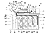
投入部11に外部から紙幣が投入されて、操作表示部14に入金処理開始の操作が入力されると、図3Aに太線で示す入金処理ルートで紙幣を搬送する。つまり、投入部11が紙幣を一枚ずつ分離して繰り出し、繰り出された紙幣を、入金搬送路21A、識別部17の内部搬送路21Bおよび直線搬送路21Cの前側送路部21Caが搬送する。内部搬送路21Bでの搬送中に、識別部17が紙幣を識別する。識別部17が受け入れ可能と識別した紙幣を、直線搬送路21Cの前側送路部21Caと後側送路部21Cbとが一時貯留部18に搬送し、一時貯留部18が一時貯留する(図3Aの太実線参照)。他方、識別部17が受け入れ不可と識別した紙幣は、直線搬送路21Cの前側送路部21Caから出金搬送路21Dが払出部12に搬送する(図3Aの太実線から太破線参照)。
投入部11に外部から紙幣が投入されて、操作表示部14に入金処理開始の操作が入力されると、図3Aに太線で示す入金処理ルートで紙幣を搬送する。つまり、投入部11が紙幣を一枚ずつ分離して繰り出し、繰り出された紙幣を、入金搬送路21A、識別部17の内部搬送路21Bおよび直線搬送路21Cの前側送路部21Caが搬送する。内部搬送路21Bでの搬送中に、識別部17が紙幣を識別する。識別部17が受け入れ可能と識別した紙幣を、直線搬送路21Cの前側送路部21Caと後側送路部21Cbとが一時貯留部18に搬送し、一時貯留部18が一時貯留する(図3Aの太実線参照)。他方、識別部17が受け入れ不可と識別した紙幣は、直線搬送路21Cの前側送路部21Caから出金搬送路21Dが払出部12に搬送する(図3Aの太実線から太破線参照)。
投入部11は厚さ方向に集積された状態の紙幣を分離して繰り出す。このため、投入部11からの繰り出し時に、重送、斜行等の搬送不良を生じる可能性がある。このような搬送不良の紙幣も識別部17が受け入れ不可と識別して払出部12に搬送させる。投入部11に投入された紙幣をすべて一時貯留部18および払出部12のいずれかに搬送した状態になると、識別部17の識別結果に基づいて一時貯留部18に一時貯留させている紙幣の金額情報を操作表示部14が表示する。この金額情報は、紙幣の金種別の枚数および総額を含む。払出部12に搬送された紙幣は、外部に取り出し可能となる。
「収納処理」
入金処理において操作表示部14により金額情報が表示された後、操作者が操作表示部14に承認操作を入力すると、図3Bに太線で示す収納処理ルートで紙幣を搬送する。つまり、一時貯留させていた紙幣を一時貯留部18が繰り出し、直線搬送路21C、識別部17の内部搬送路21B、入金搬送路21Aの後側構成部21Ab2、上下搬送路21Eの上側送路部21Eaおよび収納搬送路21Fが搬送する。内部搬送路21Bでの搬送中に、識別部17が紙幣を識別する。その識別結果に基づいて、収納搬送路21Fと分岐搬送路21G~21Iのうち適宜の搬送路とが8台の収納庫32のうち対応する収納庫32に紙幣を振り分ける。振り分けられた紙幣を8台の収納庫32のうち対応する収納庫32が収納する。
入金処理において操作表示部14により金額情報が表示された後、操作者が操作表示部14に承認操作を入力すると、図3Bに太線で示す収納処理ルートで紙幣を搬送する。つまり、一時貯留させていた紙幣を一時貯留部18が繰り出し、直線搬送路21C、識別部17の内部搬送路21B、入金搬送路21Aの後側構成部21Ab2、上下搬送路21Eの上側送路部21Eaおよび収納搬送路21Fが搬送する。内部搬送路21Bでの搬送中に、識別部17が紙幣を識別する。その識別結果に基づいて、収納搬送路21Fと分岐搬送路21G~21Iのうち適宜の搬送路とが8台の収納庫32のうち対応する収納庫32に紙幣を振り分ける。振り分けられた紙幣を8台の収納庫32のうち対応する収納庫32が収納する。
一時貯留部18は巻付収納タイプである。このため、基本的に、一時貯留部18からの繰り出し時に、重送、斜行等の搬送不良を生じない。よって、基本的に、一時貯留部18が繰り出した紙幣は識別部17で収納不可と判断されない。
「返却処理」
入金処理において操作表示部14により金額情報が表示された後、操作者が操作表示部14に返却操作を入力すると、図4に太線で示す返却処理ルートで紙幣を搬送する。つまり、一時貯留させていた紙幣を、一時貯留部18が繰り出し、直線搬送路21Cの後側送路部21Cbおよび出金搬送路21Dで払出部12に搬送する。払出部12に搬送された紙幣は、外部に取り出し可能となる。
入金処理において操作表示部14により金額情報が表示された後、操作者が操作表示部14に返却操作を入力すると、図4に太線で示す返却処理ルートで紙幣を搬送する。つまり、一時貯留させていた紙幣を、一時貯留部18が繰り出し、直線搬送路21Cの後側送路部21Cbおよび出金搬送路21Dで払出部12に搬送する。払出部12に搬送された紙幣は、外部に取り出し可能となる。
「整理計数処理」
投入部11に外部から紙幣が投入されて、操作表示部14に金種の指定が入力され、その後、整理計数処理開始の操作が入力されると、まず、図5Aに太線で示す整理計数処理の前段ルートで紙幣を搬送する。つまり、投入部11が紙幣を一枚ずつ分離して繰り出し、繰り出された紙幣を、入金搬送路21A、識別部17の内部搬送路21Bおよび直線搬送路21Cの前側送路部21Caが搬送する。内部搬送路21Bでの搬送中に、識別部17が紙幣を識別する。識別部17が指定金種の紙幣であると識別した紙幣を、直線搬送路21Cの前側送路部21Caから後側送路部21Cbが一時貯留部18に搬送し、一時貯留部18が一時貯留させる(図5Aの太実線参照)。他方、識別部17が指定金種以外の紙幣であると識別した紙幣(搬送不良紙幣を含む)は、直線搬送路21Cの前側送路部21Caから出金搬送路21Dが払出部12に搬送する(図5Aの太実線から太破線参照)。払出部12に搬送された紙幣は、外部に取り出し可能となる。
投入部11に外部から紙幣が投入されて、操作表示部14に金種の指定が入力され、その後、整理計数処理開始の操作が入力されると、まず、図5Aに太線で示す整理計数処理の前段ルートで紙幣を搬送する。つまり、投入部11が紙幣を一枚ずつ分離して繰り出し、繰り出された紙幣を、入金搬送路21A、識別部17の内部搬送路21Bおよび直線搬送路21Cの前側送路部21Caが搬送する。内部搬送路21Bでの搬送中に、識別部17が紙幣を識別する。識別部17が指定金種の紙幣であると識別した紙幣を、直線搬送路21Cの前側送路部21Caから後側送路部21Cbが一時貯留部18に搬送し、一時貯留部18が一時貯留させる(図5Aの太実線参照)。他方、識別部17が指定金種以外の紙幣であると識別した紙幣(搬送不良紙幣を含む)は、直線搬送路21Cの前側送路部21Caから出金搬送路21Dが払出部12に搬送する(図5Aの太実線から太破線参照)。払出部12に搬送された紙幣は、外部に取り出し可能となる。
投入部11に投入された紙幣をすべて一時貯留部18および払出部12のいずれかに搬送した状態になると、払出部12の紙幣が取り出されたことを条件に、図5Bに太線で示す整理計数処理の後段ルートで紙幣を搬送する。つまり、一時貯留させていた紙幣を一時貯留部18が繰り出し、直線搬送路21Cの後側送路部21Cbおよび出金搬送路21Dで払出部12に搬送する。前段ルートでの識別部17の識別結果に基づいて、払出部12に搬送した紙幣の金種(すなわち、設定金種)、枚数および総額等の金額情報を操作表示部14が表示する。払出部12に搬送された紙幣は、外部に取り出し可能となる。前段ルートで識別部17が指定金種の紙幣であると識別した紙幣のみを一時貯留部18に一時貯留している。このため、後段ルートで一時貯留部18から払出部12に搬送された紙幣は、前段ルートでの識別部17の識別結果に対応する紙幣である。よって、後段ルートでは識別部17で識別しなくても済むことになる。
「出金処理」
操作表示部14に出金させる紙幣の金額情報とともに出金処理の選択操作が入力されたことに応答して、単金種収納庫に設定された収納庫32から紙幣を出金する場合は、出金対象金種の紙幣が収納された収納庫32から図6に太線で示す出金処理ルートで紙幣を搬送する。つまり、複数の収納庫32のうちの出金対象金種に対応する収納庫32が、収納していた紙幣を計数しつつ繰り出す。さらに、繰り出された紙幣を、分岐搬送路21G~21Iのうち適宜の搬送路、収納搬送路21F、上下搬送路21Eの上側送路部21Ea、入金搬送路21Aの後側構成部21Ab2、識別部17の内部搬送路21B、直線搬送路21Cの前側送路部21Caおよび出金搬送路21Dが払出部12に搬送する。収納庫32はすべて巻付収納タイプである。このため、基本的に、収納庫32からの繰り出し時に、重送、斜行等の搬送不良を生じない。よって、基本的に、収納庫32が繰り出した紙幣は識別部17で出金不可と判断されない。払出部12に搬送された紙幣は、外部に取り出し可能となる。
操作表示部14に出金させる紙幣の金額情報とともに出金処理の選択操作が入力されたことに応答して、単金種収納庫に設定された収納庫32から紙幣を出金する場合は、出金対象金種の紙幣が収納された収納庫32から図6に太線で示す出金処理ルートで紙幣を搬送する。つまり、複数の収納庫32のうちの出金対象金種に対応する収納庫32が、収納していた紙幣を計数しつつ繰り出す。さらに、繰り出された紙幣を、分岐搬送路21G~21Iのうち適宜の搬送路、収納搬送路21F、上下搬送路21Eの上側送路部21Ea、入金搬送路21Aの後側構成部21Ab2、識別部17の内部搬送路21B、直線搬送路21Cの前側送路部21Caおよび出金搬送路21Dが払出部12に搬送する。収納庫32はすべて巻付収納タイプである。このため、基本的に、収納庫32からの繰り出し時に、重送、斜行等の搬送不良を生じない。よって、基本的に、収納庫32が繰り出した紙幣は識別部17で出金不可と判断されない。払出部12に搬送された紙幣は、外部に取り出し可能となる。
「出金退避処理」
金種混合収納庫に設定された収納庫32から紙幣を出金する場合、出金対象金種の紙幣を上記出金処理ルートで搬送し、出金対象以外の紙幣を、図7Aに太線で示す出金退避処理の前段ルートで搬送する。つまり、金種混合収納庫32から繰り出された出金対象以外の紙幣を、分岐搬送路21G~21Iのうち対応する搬送路、収納搬送路21F、上下搬送路21Eの上側送路部21Ea、入金搬送路21Aの後側構成部21Ab2、識別部17の内部搬送路21Bおよび直線搬送路21Cが一時貯留部18に搬送し、一時貯留部18が一時貯留させる。
金種混合収納庫に設定された収納庫32から紙幣を出金する場合、出金対象金種の紙幣を上記出金処理ルートで搬送し、出金対象以外の紙幣を、図7Aに太線で示す出金退避処理の前段ルートで搬送する。つまり、金種混合収納庫32から繰り出された出金対象以外の紙幣を、分岐搬送路21G~21Iのうち対応する搬送路、収納搬送路21F、上下搬送路21Eの上側送路部21Ea、入金搬送路21Aの後側構成部21Ab2、識別部17の内部搬送路21Bおよび直線搬送路21Cが一時貯留部18に搬送し、一時貯留部18が一時貯留させる。
出金対象の紙幣をすべて払出部12に搬送すると、次に、図7Bに太線で示す出金退避処理の後段ルートで紙幣を搬送する。つまり、一時貯留させていた出金対象以外の紙幣を、一時貯留部18が繰り出し、直線搬送路21C、識別部17の内部搬送路21B、入金搬送路21Aの後側構成部21Ab2、上下搬送路21Eの上側送路部21Eaおよび収納搬送路21Fが搬送する。内部搬送路21Bでの搬送中に、識別部17が紙幣を識別する。その識別結果に基づいて、収納搬送路21Fおよび分岐搬送路21G~21Iのうち適宜の搬送路が8台の収納庫32のうち対応する収納庫32に紙幣を振り分ける。振り分けられた紙幣を8台の収納庫32のうち対応する収納庫32が収納する。
「精査処理」
操作表示部14に精査処理の選択操作が入力されると、まず、図8Aに太線で示す精査処理の往路ルートで紙幣を搬送する。つまり、8台の収納庫32のうちの精査対象の1台が紙幣を繰り出す。さらに、繰り出された紙幣を、分岐搬送路21G~21Iのうち対応する搬送路、収納搬送路21F、上下搬送路21Eの上側送路部21Ea、入金搬送路21Aの後側構成部21Ab2、識別部17の内部搬送路21Bおよび直線搬送路21Cが一時貯留部18に搬送する。その紙幣を一時貯留部18が一時貯留させる。このようにして、精査対象の1台の収納庫32に収納されているすべての紙幣を、一時貯留部18に搬送する。
操作表示部14に精査処理の選択操作が入力されると、まず、図8Aに太線で示す精査処理の往路ルートで紙幣を搬送する。つまり、8台の収納庫32のうちの精査対象の1台が紙幣を繰り出す。さらに、繰り出された紙幣を、分岐搬送路21G~21Iのうち対応する搬送路、収納搬送路21F、上下搬送路21Eの上側送路部21Ea、入金搬送路21Aの後側構成部21Ab2、識別部17の内部搬送路21Bおよび直線搬送路21Cが一時貯留部18に搬送する。その紙幣を一時貯留部18が一時貯留させる。このようにして、精査対象の1台の収納庫32に収納されているすべての紙幣を、一時貯留部18に搬送する。
次に、図8Bに太線で示す精査処理の復路ルートで紙幣を搬送する。つまり、一時貯留させていた紙幣を、一時貯留部18が繰り出す。さらに、その紙幣を、直線搬送路21C、識別部17の内部搬送路21B、入金搬送路21Aの後側構成部21Ab2、上下搬送路21Eの上側送路部21Eaおよび収納搬送路21Fが搬送する。内部搬送路21Bでの搬送中に、識別部17が紙幣を識別する。その識別結果に基づいて、収納搬送路21Fと分岐搬送路21G~21Iのうち適宜の搬送路とが8台の収納庫32のうちの精査対象の1台に紙幣を搬送し、この収納庫32が紙幣を収納する。このときの識別部17の識別結果から、精査対象の収納庫32に収納された紙幣の枚数情報つまり金額情報を確定する。
上記と同様の処理を、すべての精査対象の収納庫32のそれぞれに対して行い、すべての精査対象の収納庫32の個々の金額情報を確定する。
「カセット補充処理」
カセット補充処理を行うにあたって、前方カセット31には、装置外部で紙幣が収納される。そして、蓋体37が開かれ、筐体35からユニット本体36が引き出されてユニット本体36にこの前方カセット31が、それまで取り付けられていた前方カセット31と交換で取り付けられる。
カセット補充処理を行うにあたって、前方カセット31には、装置外部で紙幣が収納される。そして、蓋体37が開かれ、筐体35からユニット本体36が引き出されてユニット本体36にこの前方カセット31が、それまで取り付けられていた前方カセット31と交換で取り付けられる。
操作表示部14にカセット補充処理の選択操作が入力されると、図9Aに太線で示すカセット補充処理の前段ルートで紙幣を搬送する。つまり、前方カセット31が紙幣を繰り出し、繰り出された紙幣を、上下搬送路21E、入金搬送路21Aの後側構成部21Ab2、識別部17の内部搬送路21Bおよび直線搬送路21Cの前側送路部21Caが搬送する。内部搬送路21Bでの搬送中に、識別部17が紙幣を識別する。その識別結果に基づいて、受け入れ可能と識別した紙幣を、直線搬送路21Cの後側送路部21Cbで一時貯留部18に搬送し、一時貯留部18が一時貯留させる(図9Aの太実線参照)。前方カセット31は集積収納タイプである。このため、前方カセット31から繰り出しされた紙幣の重送、斜行等の搬送不良の可能性がある。このような搬送不良紙幣を含む受け入れ不可と識別した紙幣については、直線搬送路21Cの前側送路部21Caから出金搬送路21Dが払出部12に搬送する(図9Aの太実線から太破線参照)。払出部12に搬送された紙幣は、外部に取り出し可能となる。
前方カセット31の収納容量は一時貯留部18の収納容量よりも大きい。このため、前方カセット31が空になる前に、一時貯留部18が満杯になる場合がある。前方カセット31が空になるか、あるいは一時貯留部18が満杯になると、図9Bに太線で示すカセット補充処理の後段ルートで紙幣を搬送する。つまり、一時貯留させていた紙幣を、一時貯留部18が繰り出し、直線搬送路21C、識別部17の内部搬送路21B、入金搬送路21Aの後側構成部21Ab2、上下搬送路21Eの上側送路部21Eaおよび収納搬送路21Fが搬送する。内部搬送路21Bでの搬送中に、識別部17が紙幣を識別する。その識別結果に基づいて、収納搬送路21Fおよび分岐搬送路21G~21Iのうち適宜の搬送路が8台の収納庫32のうち対応する収納庫32に紙幣を振り分ける。振り分けられた紙幣を8台の収納庫32の対応する収納庫32が収納する。
以上の処理を前方カセット31が空になるまで適宜繰り返す。このようにして、前方カセット31に収納された紙幣が、それぞれ8台の収納庫32のうち対応する収納庫32に振り分けられて収納される。
「入金口補充処理」
操作表示部14に入金口補充処理の選択操作が入力されると、まず、図10Aに太線で示す入金口補充処理の前段ルートで紙幣を搬送する。つまり、投入部11が紙幣を一枚ずつ分離して繰り出す。さらに、繰り出された紙幣を、入金搬送路21A、識別部17の内部搬送路21Bおよび直線搬送路21Cの前側送路部21Caが搬送する。内部搬送路21Bでの搬送中に、識別部17が紙幣を識別する。識別部17が受け入れ可能と識別した紙幣を、直線搬送路21Cの前側送路部21Caおよび後側送路部21Cbが一時貯留部18に搬送し、一時貯留部18が一時貯留させる(図10Aの太実線参照)。他方、識別部17が受け入れ不可と識別した紙幣(搬送不良紙幣を含む)は、直線搬送路21Cの前側送路部21Caから出金搬送路21Dが払出部12に搬送する(図10Aの太実線から太破線参照)。払出部12に搬送された紙幣は、外部に取り出し可能となる。
操作表示部14に入金口補充処理の選択操作が入力されると、まず、図10Aに太線で示す入金口補充処理の前段ルートで紙幣を搬送する。つまり、投入部11が紙幣を一枚ずつ分離して繰り出す。さらに、繰り出された紙幣を、入金搬送路21A、識別部17の内部搬送路21Bおよび直線搬送路21Cの前側送路部21Caが搬送する。内部搬送路21Bでの搬送中に、識別部17が紙幣を識別する。識別部17が受け入れ可能と識別した紙幣を、直線搬送路21Cの前側送路部21Caおよび後側送路部21Cbが一時貯留部18に搬送し、一時貯留部18が一時貯留させる(図10Aの太実線参照)。他方、識別部17が受け入れ不可と識別した紙幣(搬送不良紙幣を含む)は、直線搬送路21Cの前側送路部21Caから出金搬送路21Dが払出部12に搬送する(図10Aの太実線から太破線参照)。払出部12に搬送された紙幣は、外部に取り出し可能となる。
投入部11に投入された紙幣をすべて一時貯留部18および払出部12のいずれかに搬送した状態になると、図10Bに太線で示す入金口補充処理の後段ルートで紙幣を搬送する。つまり、一時貯留させていた紙幣を、一時貯留部18が繰り出す。その紙幣を、直線搬送路21C、識別部17の内部搬送路21B、入金搬送路21Aの後側構成部21Ab2、上下搬送路21Eの上側送路部21Eaおよび収納搬送路21Fが搬送する。内部搬送路21Bでの搬送中に、識別部17が紙幣を識別する。その識別結果に基づいて、収納搬送路21Fおよび分岐搬送路21G~21Iのうち適宜の搬送路が8台の収納庫32うちの対応する収納庫3に紙幣を振り分ける。振り分けられた紙幣を8台の収納庫32のうち対応する収納庫32が収納する。このようにして、投入部11に投入された紙幣が、それぞれ8台の収納庫32のうち対応する収納庫32に振り分けられて収納される。
「回収処理」
操作表示部14に回収処理の選択操作が入力されると、図11Aに太線で示す回収処理の前段ルートで紙幣を搬送する。つまり、8台の収納庫32のうちの回収対象の1台が紙幣を繰り出す。さらに、繰り出された紙幣を、分岐搬送路21G~21Iのうち適宜の搬送路、収納搬送路21F、上下搬送路21Eの上側送路部21Ea、入金搬送路21Aの後側構成部21Ab2、識別部17の内部搬送路21Bおよび直線搬送路21Cが一時貯留部18に搬送し、一時貯留部18が一時貯留させる。このようにして、回収対象の1台の収納庫32のすべての紙幣を、一時貯留部18に搬送する。
操作表示部14に回収処理の選択操作が入力されると、図11Aに太線で示す回収処理の前段ルートで紙幣を搬送する。つまり、8台の収納庫32のうちの回収対象の1台が紙幣を繰り出す。さらに、繰り出された紙幣を、分岐搬送路21G~21Iのうち適宜の搬送路、収納搬送路21F、上下搬送路21Eの上側送路部21Ea、入金搬送路21Aの後側構成部21Ab2、識別部17の内部搬送路21Bおよび直線搬送路21Cが一時貯留部18に搬送し、一時貯留部18が一時貯留させる。このようにして、回収対象の1台の収納庫32のすべての紙幣を、一時貯留部18に搬送する。
次に、図11Bに太線で示す回収処理の後段ルートで紙幣を搬送する。つまり、一時貯留させていた紙幣を、一時貯留部18が繰り出す。さらに、直線搬送路21C、識別部17の内部搬送路21B、入金搬送路21Aの後側構成部21Ab2および上下搬送路21Eが前方カセット31に搬送し、前方カセット31が収納する。
このような処理を、複数の収納庫32のうち回収が指定された収納庫32に対して行う(全部の収納庫32が指定される場合もある)。その後、蓋体37が開かれ、筐体35からユニット本体36が引き出されてユニット本体36から前方カセット31が取り外される。
以上に述べた第1実施形態によれば、識別部17と一時貯留部18とが一直線の直線搬送路21Cで接続されており、紙幣が識別部17で識別後に直線搬送路21Cで一時貯留部18に搬送される。このため、識別部17から一時貯留部18に紙幣が湾曲した状態で搬送されることがない。したがって、ジャムの発生を抑制することができる。更に、紙幣が一時貯留部18から識別部17に搬送される際にも、紙幣が直線搬送路21Cで搬送される。このため、一時貯留部18から識別部17に紙幣が湾曲した状態で搬送されることがない。したがって、ジャムの発生を抑制することができる。
また、高さ方向の位置を重ね合わせた(合わせた)識別部17と一時貯留部18とを直線搬送路21Cが横方向に延在して接続している。このため、紙葉類処理装置10の高さ方向の長さを短くすることが可能となり、紙葉類処理装置10の全体の小型化を図ることが可能となる。
また、投入された紙幣を識別部17に向けて繰り出す投入部11と、投入部11から繰り出された紙幣を識別する識別部17と、識別部17で識別後の紙幣が直線搬送路21Cで搬送されてくる一時貯留部18とが、紙葉類処理装置10の前方から紙葉類処理装置10の後方に向かって、この順に配置されている。このため、投入部11が、識別部17や一時貯留部18と上下に積層されることがない。よって、紙葉類処理装置10の高さ方向の長さを短くすることが可能となり、紙葉類処理装置10の全体の小型化を図ることが可能となる。
また、紙葉類処理装置10は、処理する紙葉類が紙幣であるため、紙幣のジャムの発生を抑制することができる。
収納庫32を8台設けることに限定されない。収納庫32を、7台以下設けるようにしても良く、9台以上設けるようにしても良い。また、上下に並べられた2段の収納庫32,32を数列設けることに限定されない。1段の収納庫32を数列設けるようにしても良い。
本発明の第2実施形態に係る紙葉類処理装置を主に図12~図16Bを参照して第1実施形態との相違部分を中心に以下に説明する。第2実施形態では、第1実施形態の8台の収納庫32のうち、後側3列の上下に並べられた2段の合計6台の収納庫32にかえて、3台の収納庫51が設けられている。収納庫51の高さは、収納庫32の2台分の高さと同等である。3台の収納庫51は、上下に並べられた2段の収納庫32と高さ方向の位置を重ね合わせて(合わせて)いる。
3台の収納庫51は、いずれも、紙幣を一枚ずつ取り込んで収納可能であり、収納している紙幣を一枚ずつ繰り出し可能となっている。3台の収納庫51は、いずれも、紙幣を上部から受け入れて水平状態で下から上に集積させて収納するとともに収納している紙幣を上端部の紙幣から繰り出す集積収納タイプとなっている。このため、3台の収納庫51から紙幣を繰り出す場合に、繰り出した紙幣に、重送、斜行等の搬送不良の可能性がある。第2実施形態では、その場合の搬送ルートが第1実施形態と異なっている。集積収納タイプの収納庫51は、一時貯留部18および収納庫32のような巻付収納タイプに比べて紙幣の収納効率が大幅に高い。3台の収納庫51の収納容量は、互いに同等である。各収納庫51の収納容量は、前方カセット31とも同等になっている。
第2実施形態では、2台の収納庫32が金種混合収納庫に設定されており、3台の収納庫51が単金種収納庫に設定されている。単金種収納庫および金種混合収納庫の設定は任意で可能であるが、3台の収納庫51は単金種収納庫に設定するのが好ましい。
次に、第2実施形態に係る紙葉類処理装置10の作動について各処理別に説明する。
「入金処理」
第1実施形態の図3Aに太線で示す入金処理ルートと同様のルートで、投入部11に投入された紙幣を識別部17で識別し、受け入れ可能と識別した紙幣を一時貯留部18に一時貯留させ(図3Aの太実線参照)、受け入れ不可と識別した紙幣(搬送不良紙幣を含む)を払出部12に搬送する(図3Aの太実線から太破線参照)。
第1実施形態の図3Aに太線で示す入金処理ルートと同様のルートで、投入部11に投入された紙幣を識別部17で識別し、受け入れ可能と識別した紙幣を一時貯留部18に一時貯留させ(図3Aの太実線参照)、受け入れ不可と識別した紙幣(搬送不良紙幣を含む)を払出部12に搬送する(図3Aの太実線から太破線参照)。
「収納処理」
第1実施形態の図3Bに太線で示す収納処理ルートと同様のルートで、一時貯留部18に一時貯留させていた紙幣を識別部17で識別し、その結果に基づいて、上下2台の収納庫32および3台の収納庫51の対応するものに収納させる。
第1実施形態の図3Bに太線で示す収納処理ルートと同様のルートで、一時貯留部18に一時貯留させていた紙幣を識別部17で識別し、その結果に基づいて、上下2台の収納庫32および3台の収納庫51の対応するものに収納させる。
「返却処理」
第1実施形態の図4に太線で示す返却処理ルートと同様のルートで、一時貯留部18に一時貯留させていた紙幣を払出部12に搬送する。
第1実施形態の図4に太線で示す返却処理ルートと同様のルートで、一時貯留部18に一時貯留させていた紙幣を払出部12に搬送する。
「整理計数処理」
第1実施形態の図5Aに太線で示す整理計数処理の前段ルートと同様のルートで、投入部11に投入された紙幣を識別部17で識別し、指定金種と識別した紙幣を一時貯留部18に一時貯留させ(図5Aの太実線参照)、指定金種以外と識別した紙幣(搬送不良紙幣を含む)を払出部12に搬送する(図5Aの太実線から太破線参照)。次に、第1実施形態の図5Bに太線で示す整理計数処理の後段ルートと同様のルートで、一時貯留部18に一時貯留させていた紙幣を払出部12に搬送し、前段ルートで一時貯留部18に一時貯留させた紙幣についての識別部17の識別結果を操作表示部14に表示させる。
第1実施形態の図5Aに太線で示す整理計数処理の前段ルートと同様のルートで、投入部11に投入された紙幣を識別部17で識別し、指定金種と識別した紙幣を一時貯留部18に一時貯留させ(図5Aの太実線参照)、指定金種以外と識別した紙幣(搬送不良紙幣を含む)を払出部12に搬送する(図5Aの太実線から太破線参照)。次に、第1実施形態の図5Bに太線で示す整理計数処理の後段ルートと同様のルートで、一時貯留部18に一時貯留させていた紙幣を払出部12に搬送し、前段ルートで一時貯留部18に一時貯留させた紙幣についての識別部17の識別結果を操作表示部14に表示させる。
「出金処理」
操作表示部14に、出金させる紙幣の金額情報とともに出金処理の選択操作が入力されると、2台の収納庫32および3台の収納庫51のうちの出金対象金種の紙幣が収納されている収納庫から図13に太線で示す出金処理ルートで紙幣を搬送する。つまり、2台の収納庫32および3台の収納庫51のうち対応する収納庫が収納していた紙幣を繰り出す。さらに、繰り出された紙幣を、分岐搬送路21G~21Iのうち適宜の搬送路、収納搬送路21F、上下搬送路21Eの上側送路部21Ea、入金搬送路21Aの後側構成部21Ab2、識別部17の内部搬送路21B、直線搬送路21Cの前側送路部21Caが搬送する。内部搬送路21Bでの搬送中に識別部17が識別し、識別部17で出金可能と判断された紙幣を、出金搬送路21Dが払出部12に搬送する(図13の太実線参照)。
操作表示部14に、出金させる紙幣の金額情報とともに出金処理の選択操作が入力されると、2台の収納庫32および3台の収納庫51のうちの出金対象金種の紙幣が収納されている収納庫から図13に太線で示す出金処理ルートで紙幣を搬送する。つまり、2台の収納庫32および3台の収納庫51のうち対応する収納庫が収納していた紙幣を繰り出す。さらに、繰り出された紙幣を、分岐搬送路21G~21Iのうち適宜の搬送路、収納搬送路21F、上下搬送路21Eの上側送路部21Ea、入金搬送路21Aの後側構成部21Ab2、識別部17の内部搬送路21B、直線搬送路21Cの前側送路部21Caが搬送する。内部搬送路21Bでの搬送中に識別部17が識別し、識別部17で出金可能と判断された紙幣を、出金搬送路21Dが払出部12に搬送する(図13の太実線参照)。
3台の収納庫51は集積収納タイプであるため、収納庫51からの紙幣の繰り出し時に、重送、斜行等の搬送不良を生じる可能性がある。このような搬送不良紙幣は、識別部17で出金不可と判断されて、直線搬送路21Cの後側送路部21Cbが一時貯留部18に搬送し、一時貯留部18が一時貯留させる(図13の太実線から太破線参照)。巻付収納タイプの2台の収納庫32は金種混合収納庫に設定されている。このため、収納庫32は、繰り出し時に、出金対象金種以外の紙幣を繰り出すことがある。このような出金対象金種以外であると識別部17で識別された紙幣も、直線搬送路21Cの後側送路部21Cbが一時貯留部18に搬送し、一時貯留部18が一時貯留させる(図13の太実線から太破線参照)。その後、すべての出金対象の紙幣を払出部12に搬送すると、一時貯留部18に一時貯留させていた紙幣を識別部17で識別する。その識別結果に基づいて、紙幣を2台の収納庫32および3台の収納庫51のうち対応する収納庫に収納させる。例えば、正常搬送紙幣は、3台の収納庫51のうち、その紙幣の金種に対応する金種を収容するように設定されている収納庫51に収納される。搬送不良紙幣は、金種混合の2台の収納庫32のうちの適宜の収納庫32に収納される。
「精査処理」
上下に並べられた2台の巻付収納タイプの収納庫32は、搬送不良紙幣を収納している可能性があるため、精査対象とはしない。単金種収納庫に設定された集積収納タイプの3台の収納庫51が精査対象となる。収納庫51のうちの精査対象の収納庫51から、図14Aに太線で示す精査処理の往路処理の前段ルートで紙幣を搬送する。つまり、収納庫51のうちの精査対象の1台が紙幣を繰り出す。さらに、繰り出された紙幣を分岐搬送路21H,21Iのうちの適宜の分岐搬送路が、収納搬送路21F、上下搬送路21Eの上側送路部21Ea、入金搬送路21Aの後側構成部21Ab2、識別部17の内部搬送路21Bおよび直線搬送路21Cが一時貯留部18に搬送し、一時貯留部18が一時貯留させる。このとき、集積収納タイプの収納庫51から繰り出されることによって搬送不良紙幣となる紙幣もある。このような搬送不良紙幣もそのまま一時貯留部18に一時貯留させる。
上下に並べられた2台の巻付収納タイプの収納庫32は、搬送不良紙幣を収納している可能性があるため、精査対象とはしない。単金種収納庫に設定された集積収納タイプの3台の収納庫51が精査対象となる。収納庫51のうちの精査対象の収納庫51から、図14Aに太線で示す精査処理の往路処理の前段ルートで紙幣を搬送する。つまり、収納庫51のうちの精査対象の1台が紙幣を繰り出す。さらに、繰り出された紙幣を分岐搬送路21H,21Iのうちの適宜の分岐搬送路が、収納搬送路21F、上下搬送路21Eの上側送路部21Ea、入金搬送路21Aの後側構成部21Ab2、識別部17の内部搬送路21Bおよび直線搬送路21Cが一時貯留部18に搬送し、一時貯留部18が一時貯留させる。このとき、集積収納タイプの収納庫51から繰り出されることによって搬送不良紙幣となる紙幣もある。このような搬送不良紙幣もそのまま一時貯留部18に一時貯留させる。
精査対象の収納庫51が空になるか、一時貯留部18が満杯になると、図14Bに太線で示す精査処理の往路処理の後段ルートで紙幣を搬送する。つまり、一時貯留させていた紙幣を、一時貯留部18が繰り出す。さらに、その紙幣を直線搬送路21C、識別部17の内部搬送路21B、入金搬送路21Aの後側構成部21Ab2および上下搬送路21Eの上側送路部21Eaが搬送する。内部搬送路21Bでの搬送中に、識別部17が紙幣を識別する。精査対象の金種の紙幣を上下搬送路21Eの下側送路部21Ebが前方カセット31に搬送し、前方カセット31が収納する(図14Bの太実線参照)。精査対象以外の金種の紙幣(搬送不良紙幣を含む)を、収納搬送路21Fおよび分岐搬送路21Gが金種混合収納庫に設定された収納庫32に搬送し、この収納庫32が収納する(図14Bの太実線から太破線参照)。
以上の精査処理の往路処理を精査対象の収納庫51が空になるまで適宜繰り返す。
次に、図15Aに太線で示す精査処理の復路処理の前段ルートで紙幣を搬送する。つまり、前方カセット31が紙幣を繰り出す。さらに、繰り出された紙幣を、上下搬送路21E、入金搬送路21Aの後側構成部21Ab2、識別部17の内部搬送路21Bおよび直線搬送路21Cが一時貯留部18に搬送し、一時貯留部18が一時貯留させる。このとき、集積収納タイプの前方カセット31から繰り出されることによって搬送不良紙幣となる紙幣もある。このような搬送不良紙幣もそのまま一時貯留部18に一時貯留させる。
前方カセット31が空になるか、一時貯留部18が満杯になると、図15Bに太線で示す精査処理の復路処理の後段ルートで紙幣を搬送する。つまり、一時貯留させていた紙幣を、一時貯留部18が繰り出し、直線搬送路21C、識別部17の内部搬送路21B、入金搬送路21Aの後側構成部21Ab2、上下搬送路21Eの上側送路部21Eaおよび収納搬送路21Fが搬送する。内部搬送路21Bでの搬送中に、識別部17が紙幣を識別する。その識別結果に基づいて、精査対象の紙幣を、収納搬送路21Fおよび分岐搬送路21H,21Iのうち適宜の搬送路が3台の収納庫51のうちの精査対象の1台に搬送し、この収納庫51が収納する(図15Bの太実線参照)。精査対象以外の金種の紙幣(搬送不良紙幣を含む)を、収納搬送路21Fおよび分岐搬送路21Gが金種混合収納庫に設定された収納庫32に搬送し、この収納庫32が収納する(図15Bの太実線から太破線参照)。
以上の精査処理の復路処理を前方カセット31が空になるまで適宜繰り返す。そして、精査処理の復路処理時の後段ルートでの識別部17の識別結果から、精査対象の収納庫51へ収納した紙幣の枚数情報つまり金額情報を確定する。
上記と同様の処理を、すべての精査対象の収納庫51のそれぞれに対して行い、すべての精査対象の収納庫51の個々の金額情報を確定する。
「カセット補充処理」
第1実施形態の図9Aに太線で示すカセット補充処理の前段ルートと同様のルートで、前方カセット31から繰り出された紙幣を識別部17で識別し、その識別結果に基づいて、受け入れ可能と識別した紙幣を一時貯留部18に一時貯留させる(図9Aの太実線参照)一方、識別部17で受け入れ不可と識別した紙幣を払出部12に搬送する(図9Aの太実線から太破線参照)。
第1実施形態の図9Aに太線で示すカセット補充処理の前段ルートと同様のルートで、前方カセット31から繰り出された紙幣を識別部17で識別し、その識別結果に基づいて、受け入れ可能と識別した紙幣を一時貯留部18に一時貯留させる(図9Aの太実線参照)一方、識別部17で受け入れ不可と識別した紙幣を払出部12に搬送する(図9Aの太実線から太破線参照)。
前方カセット31が空になるか、あるいは一時貯留部18が満杯になると、第1実施形態の図9Bに太線で示すカセット補充処理の後段ルートと同様のルートで紙幣を搬送する。つまり、一時貯留部18に一時貯留させていた紙幣を識別部17で識別し、その識別結果に基づいて、単金種収納庫に設定された3台の収納庫51うちの対応する収納庫51に紙幣を振り分ける。以上の処理を前方カセット31が空になるまで適宜繰り返す。
「入金口補充処理」
第1実施形態の図10Aに太線で示す入金口補充処理の前段ルートと同様のルートで、投入部11に投入された紙幣を識別部17で識別する。識別部17が受け入れ可能と識別した紙幣を一時貯留部18に一時貯留させる(図10Aの太実線参照)一方、識別部17が受け入れ不可と識別した紙幣を払出部12に搬送する(図10Aの太実線から太破線参照)。
第1実施形態の図10Aに太線で示す入金口補充処理の前段ルートと同様のルートで、投入部11に投入された紙幣を識別部17で識別する。識別部17が受け入れ可能と識別した紙幣を一時貯留部18に一時貯留させる(図10Aの太実線参照)一方、識別部17が受け入れ不可と識別した紙幣を払出部12に搬送する(図10Aの太実線から太破線参照)。
次に、第1実施形態の図10Bに太線で示す入金口補充処理の後段ルートと同様のルートで、一時貯留部18に一時貯留されていた紙幣を識別部17で識別する。その識別結果に基づいて、2台の収納庫32および3台の収納庫51うちの対応する収納庫に紙幣を振り分ける。
「回収処理」
図16Aに太線で示す回収処理の前段ルートで紙幣を搬送する。つまり、単金種収納庫に設定された3台の収納庫51のうちの回収対象の1台が紙幣を繰り出し、繰り出された紙幣を第1実施形態と同様のルートで搬送して、一時貯留部18に一時貯留させる。このとき、集積収納タイプの収納庫51から繰り出されることによって搬送不良紙幣となる紙幣もある。このような搬送不良紙幣もそのまま一時貯留部18に一時貯留させる。
図16Aに太線で示す回収処理の前段ルートで紙幣を搬送する。つまり、単金種収納庫に設定された3台の収納庫51のうちの回収対象の1台が紙幣を繰り出し、繰り出された紙幣を第1実施形態と同様のルートで搬送して、一時貯留部18に一時貯留させる。このとき、集積収納タイプの収納庫51から繰り出されることによって搬送不良紙幣となる紙幣もある。このような搬送不良紙幣もそのまま一時貯留部18に一時貯留させる。
回収対象の収納庫51が空になるか、一時貯留部18が満杯になると、図16Bに太線で示す回収処理の後段ルートで紙幣を搬送する。つまり、一時貯留させていた紙幣を、一時貯留部18が繰り出す。さらに、直線搬送路21C、識別部17の内部搬送路21B、入金搬送路21Aの後側構成部21Ab2および上下搬送路21Eの上側送路部21Eaが搬送する。内部搬送路21Bでの搬送中に、識別部17が紙幣を識別する。その識別結果に基づいて、回収対象の紙幣を、上下搬送路21Eの下側送路部21Ebが前方カセット31に搬送し、前方カセット31が収納する(図16Bの太実線参照)。回収対象以外の紙幣(搬送不良紙幣を含む)を、収納搬送路21Fおよび分岐搬送路21Gが金種混合収納庫に設定された収納庫32に搬送し、この収納庫32が収納する(図16Bの太実線から太破線参照)。
以上の処理を回収対象の収納庫51が空になるまで適宜繰り返す。その後、蓋体37が開かれ、筐体35からユニット本体36が引き出されてユニット本体36から前方カセット31が取り外される。複数台の収納庫51の合計の紙幣量によっては、これら収納庫51の紙幣を一度に前方カセット31に収納して回収することも可能である。
また、金種混合収納庫に設定された収納庫32に収納された紙幣は、後に、出金処理と同様のルートで払出部12に搬送されて取り出される。
収納庫51を3台設けることに限定されない。収納庫51を、2台以下設けるようにしても良く、4台以上設けるようにしても良い。また、上下に並べられた2段の収納庫32を1列設けることに限定されない。2段の収納庫32を2列以上設けるようにしても良い。更に、上下に並べられた2段の収納庫32,32を1列又は数列設けることに限定されない。1段の収納庫32を1列又は数列設けるようにしても良い。
本発明の実施形態にかかる紙葉類処理装置は、紙葉類を識別する識別部と、前記識別された紙葉類を一時貯留する一時貯留部と、前記識別部と前記一時貯留部とを接続し、一直線に延び、前記識別部によって識別された紙葉類を前記一時貯留部に搬送する直線搬送路と、を備える。上記紙葉類処理装置は、高さ方向における前記識別部の位置が前記高さ方向における前記一時貯留部の位置と合わされており、前記直線搬送路が横方向に延びている。
上記紙葉類処理装置によれば、高さ方向の位置が合わせられた識別部と一時貯留部とが横方向に延びる直線搬送路によって接続されている。このため、装置の高さ方向の長さを短くすることが可能となり、装置全体の小型化を図ることが可能となる。
上記紙葉類処理装置は、紙葉類が投入され、前記投入された紙葉類を前記識別部に向けて繰り出す投入部を更に備え、前記識別部は、前記投入された紙葉類を識別し、前記直線搬送路は、前記投入されかつ識別された紙葉類を前記一時貯留部に搬送し、前記投入部と前記識別部と前記一時貯留部とが、前記紙葉類処理装置の前方から前記紙葉類処理装置の後方に向かって、前記投入部、前記識別部、前記一時貯留部の順に配置されている。
上記紙葉類処理装置によれば、投入された紙葉類を識別部に向けて繰り出す投入部と、投入部から繰り出された紙葉類を識別する識別部と、識別部で識別後の紙葉類が直線搬送路で搬送されてくる一時貯留部とが、装置前方から、この順に配置されている。このため、投入部が、識別部や一時貯留部と上下に積層されることがない。よって、装置の高さ方向の長さを短くすることが可能となり、装置全体の小型化を図ることが可能となる。
上記紙葉類処理装置において、前記紙葉類が紙幣である。
上記紙葉類処理装置によれば、処理する紙葉類が紙幣であるため、紙幣のジャムの発生を抑制することができる。
本発明は、紙葉類処理装置に適用してもよい。
10 紙葉類処理装置
11 投入部
17 識別部
18 一時貯留部
21C 直線搬送路
11 投入部
17 識別部
18 一時貯留部
21C 直線搬送路
Claims (8)
- 紙葉類を識別する識別部と、
前記識別された紙葉類を一時貯留する一時貯留部と、
前記識別部と前記一時貯留部とを接続し、一直線に延び、前記識別部によって識別された紙葉類を前記一時貯留部に搬送する直線搬送路と、
を備える紙葉類処理装置。 - 高さ方向における前記識別部の位置が前記高さ方向における前記一時貯留部の位置と合わされており、前記直線搬送路が横方向に延びている請求項1に記載の紙葉類処理装置。
- 垂直方向における前記識別部の位置が前記垂直方向における前記一時貯留部の位置と合わされており、前記直線搬送路が水平方向に延びている請求項1に記載の紙葉類処理装置。
- 前記直線搬送路は、前記識別された紙葉類の垂直方向における位置を維持したまま、前記識別された紙葉類を、前記識別部から前記一時貯留部まで水平に搬送する請求項1乃至3のいずれか一項に記載の紙葉類処理装置。
- 前記直線搬送路は、前記識別された紙葉類が湾曲していない状態を維持したまま、前記識別された紙葉類を、前記識別部から前記一時貯留部まで搬送する請求項1乃至4のいずれか一項に記載の紙葉類処理装置。
- 前記直線搬送路は、前記識別部と接続する第1端と前記一時貯留部と接続する第2端とを有し、前記第1端から前記第2端まで一直線に延びる請求項1乃至5のいずれか一項に記載の紙葉類処理装置。
- 紙葉類が投入され、前記投入された紙葉類を前記識別部に向けて繰り出す投入部を更に備え、
前記識別部は、前記投入された紙葉類を識別し、
前記直線搬送路は、前記投入されかつ識別された紙葉類を前記一時貯留部に搬送し、
前記投入部と前記識別部と前記一時貯留部とが、前記紙葉類処理装置の前方から前記紙葉類処理装置の後方に向かって、前記投入部、前記識別部、前記一時貯留部の順に配置されている請求項1乃至6のいずれか一項に記載の紙葉類処理装置。 - 前記紙葉類が紙幣である請求項1乃至7のいずれか一項に記載の紙葉類処理装置。
Priority Applications (5)
| Application Number | Priority Date | Filing Date | Title |
|---|---|---|---|
| EP16827667.3A EP3327681A4 (en) | 2015-07-17 | 2016-07-12 | DEVICE FOR PROCESSING PAPER SHEET |
| CN201680041615.6A CN107851343A (zh) | 2015-07-17 | 2016-07-12 | 纸张类处理装置 |
| RU2018100894A RU2678302C1 (ru) | 2015-07-17 | 2016-07-12 | Устройство для обработки бумажных листов |
| US15/741,849 US20180204404A1 (en) | 2015-07-17 | 2016-07-12 | Paper sheet processing device |
| HK18107448.3A HK1248025A1 (zh) | 2015-07-17 | 2016-07-12 | 纸张类处理装置 |
Applications Claiming Priority (2)
| Application Number | Priority Date | Filing Date | Title |
|---|---|---|---|
| JP2015-142881 | 2015-07-17 | ||
| JP2015142881A JP2017027198A (ja) | 2015-07-17 | 2015-07-17 | 紙葉類処理装置 |
Publications (1)
| Publication Number | Publication Date |
|---|---|
| WO2017014107A1 true WO2017014107A1 (ja) | 2017-01-26 |
Family
ID=57834919
Family Applications (1)
| Application Number | Title | Priority Date | Filing Date |
|---|---|---|---|
| PCT/JP2016/070561 Ceased WO2017014107A1 (ja) | 2015-07-17 | 2016-07-12 | 紙葉類処理装置 |
Country Status (7)
| Country | Link |
|---|---|
| US (1) | US20180204404A1 (ja) |
| EP (1) | EP3327681A4 (ja) |
| JP (1) | JP2017027198A (ja) |
| CN (1) | CN107851343A (ja) |
| HK (1) | HK1248025A1 (ja) |
| RU (1) | RU2678302C1 (ja) |
| WO (1) | WO2017014107A1 (ja) |
Cited By (1)
| Publication number | Priority date | Publication date | Assignee | Title |
|---|---|---|---|---|
| RU2753960C1 (ru) * | 2018-01-26 | 2021-08-24 | Лорел Присижн Машинз Ко., Лтд. | Устройство обработки бумажных листов |
Families Citing this family (15)
| Publication number | Priority date | Publication date | Assignee | Title |
|---|---|---|---|---|
| US20190172292A1 (en) * | 2016-07-29 | 2019-06-06 | Glory Ltd. | Money handling device and money handling method |
| US11810416B2 (en) | 2017-03-15 | 2023-11-07 | Glory Ltd. | Sheet processing apparatus and sheet processing method |
| JP6956408B2 (ja) * | 2018-01-26 | 2021-11-02 | ローレル精機株式会社 | 紙葉類処理装置 |
| JP7056295B2 (ja) * | 2018-03-26 | 2022-04-19 | 沖電気工業株式会社 | 媒体取扱装置 |
| JP2020046705A (ja) * | 2018-09-14 | 2020-03-26 | グローリー株式会社 | 紙葉類処理装置,紙葉類処理サーバ及び紙葉類処理システム |
| US20220012973A1 (en) * | 2018-11-22 | 2022-01-13 | Oki Electric Industry Co., Ltd. | Transaction device |
| JP7171391B2 (ja) * | 2018-11-28 | 2022-11-15 | 日立チャネルソリューションズ株式会社 | 紙葉類仕分けシステム |
| JP7179292B2 (ja) | 2019-03-14 | 2022-11-29 | ローレルバンクマシン株式会社 | 紙葉類処理装置および紙葉類処理方法 |
| EP3961589B1 (en) * | 2019-04-24 | 2025-06-25 | Glory Ltd. | Bill processing device and money dispensing method |
| JP2021033647A (ja) * | 2019-08-23 | 2021-03-01 | グローリー株式会社 | 貨幣処理装置 |
| US20220383688A1 (en) * | 2019-10-25 | 2022-12-01 | Laurel Bank Machines Co., Ltd. | Coin deposit processor |
| JP7368183B2 (ja) * | 2019-10-30 | 2023-10-24 | グローリー株式会社 | 貨幣入出金装置、貨幣処理システム及び貨幣処理方法 |
| US20210174627A1 (en) * | 2019-12-10 | 2021-06-10 | Jcm American Corporation | Methods to Reduce Jamming in a Drum Style Bill Handler and Recycler |
| JP2021105894A (ja) * | 2019-12-27 | 2021-07-26 | グローリー株式会社 | 紙葉類処理装置 |
| US11663874B1 (en) | 2021-08-03 | 2023-05-30 | Wells Fargo Bank, N.A. | Mixed denomination cash cassette currency counter |
Citations (3)
| Publication number | Priority date | Publication date | Assignee | Title |
|---|---|---|---|---|
| JPH0668337A (ja) * | 1992-08-20 | 1994-03-11 | Omron Corp | 紙葉類処理装置 |
| JP2000020791A (ja) * | 1998-06-30 | 2000-01-21 | Laurel Bank Mach Co Ltd | 紙幣処理機 |
| JP2006350415A (ja) * | 2005-06-13 | 2006-12-28 | Hitachi Omron Terminal Solutions Corp | 現金取扱装置 |
Family Cites Families (40)
| Publication number | Priority date | Publication date | Assignee | Title |
|---|---|---|---|---|
| JPH06187540A (ja) * | 1992-12-21 | 1994-07-08 | Omron Corp | 紙幣搬送速度制御装置 |
| EP0907152B1 (en) * | 1997-10-06 | 2009-09-23 | Hitachi-Omron Terminal Solutions, Corp. | Leaflets handling apparatus |
| JP3558856B2 (ja) * | 1998-02-20 | 2004-08-25 | ローレルバンクマシン株式会社 | 紙幣入出金機 |
| IT1310164B1 (it) * | 1999-01-21 | 2002-02-11 | Cima Spa Di Razzaboni E C | Cassaforte selezionatrice ed erogatrice automatica di banconote |
| CA2299827C (en) * | 2000-03-02 | 2009-12-15 | Cashcode Company Inc. | Combination banknote validator and banknote dispenser |
| US7066335B2 (en) * | 2001-12-19 | 2006-06-27 | Pretech As | Apparatus for receiving and distributing cash |
| JP4362339B2 (ja) * | 2003-09-16 | 2009-11-11 | 日立オムロンターミナルソリューションズ株式会社 | 紙幣取扱装置 |
| JP5125006B2 (ja) * | 2006-07-06 | 2013-01-23 | 沖電気工業株式会社 | 紙幣処理装置 |
| WO2008059557A1 (en) * | 2006-11-13 | 2008-05-22 | Glory Ltd. | Bill handling device |
| CA2599775A1 (en) * | 2007-08-30 | 2009-02-28 | Crane Canada Co. | Energy-efficient compact device for dispensing and accumulating bank notes |
| US8630475B2 (en) * | 2007-12-10 | 2014-01-14 | Glory Ltd. | Banknote handling machine and banknote handling method |
| US8327994B2 (en) * | 2008-09-11 | 2012-12-11 | Toshiba International Corporation | Note processing gross defects removal method and apparatus |
| WO2010049968A1 (ja) * | 2008-10-28 | 2010-05-06 | グローリー株式会社 | 貨幣処理装置 |
| JP5434286B2 (ja) * | 2009-06-11 | 2014-03-05 | 沖電気工業株式会社 | 紙幣入出金機 |
| US9189909B2 (en) * | 2009-09-25 | 2015-11-17 | Glory Ltd. | Banknote handling apparatus |
| JP5384278B2 (ja) * | 2009-10-05 | 2014-01-08 | 日立オムロンターミナルソリューションズ株式会社 | 紙幣取扱装置 |
| JP5485388B2 (ja) * | 2010-06-07 | 2014-05-07 | グローリー株式会社 | 紙葉類収納操出装置、紙葉類処理装置、及び紙葉類収納方法 |
| WO2012115055A1 (ja) * | 2011-02-22 | 2012-08-30 | グローリー株式会社 | 紙幣処理装置 |
| EP2690606B1 (en) * | 2011-03-22 | 2021-02-24 | Glory Ltd. | Bill processing device |
| JP2012226494A (ja) * | 2011-04-18 | 2012-11-15 | Glory Ltd | 紙葉類処理装置 |
| JP5742451B2 (ja) * | 2011-05-11 | 2015-07-01 | 沖電気工業株式会社 | 紙幣入出金装置 |
| JP5600804B2 (ja) * | 2011-06-03 | 2014-10-01 | 日立オムロンターミナルソリューションズ株式会社 | 紙幣収納庫および紙幣取扱装置 |
| EP2918532B1 (en) * | 2011-06-27 | 2020-09-02 | Glory Ltd. | Banknote storing/feeding unit |
| JP2013012056A (ja) * | 2011-06-29 | 2013-01-17 | Glory Ltd | 紙幣処理装置および硬貨処理装置 |
| JP5775774B2 (ja) * | 2011-09-27 | 2015-09-09 | グローリー株式会社 | 貨幣処理装置 |
| JP5821504B2 (ja) * | 2011-10-12 | 2015-11-24 | 沖電気工業株式会社 | 媒体収納装置及び媒体処理装置 |
| JP5786694B2 (ja) * | 2011-12-05 | 2015-09-30 | 沖電気工業株式会社 | 紙幣処理装置 |
| JP5853798B2 (ja) * | 2012-03-21 | 2016-02-09 | 沖電気工業株式会社 | 媒体処理装置 |
| JP5790567B2 (ja) * | 2012-03-28 | 2015-10-07 | 沖電気工業株式会社 | 媒体処理装置 |
| JP6438642B2 (ja) * | 2012-12-20 | 2018-12-19 | 沖電気工業株式会社 | 紙葉類取扱装置 |
| JP5971147B2 (ja) * | 2013-02-14 | 2016-08-17 | 沖電気工業株式会社 | 媒体処理装置 |
| JP6409502B2 (ja) * | 2014-03-31 | 2018-10-24 | 沖電気工業株式会社 | 媒体処理装置及び媒体取引装置 |
| CN103955990B (zh) * | 2014-05-04 | 2017-01-25 | 上海古鳌电子科技股份有限公司 | 一种具有外汇兑换功能的纸张类处理系统 |
| CN203882375U (zh) * | 2014-05-04 | 2014-10-15 | 上海古鳌电子科技股份有限公司 | 一种具有外汇兑换功能的纸张类处理系统 |
| CN203950393U (zh) * | 2014-05-30 | 2014-11-19 | 上海古鳌电子科技股份有限公司 | 一种现金自动交易装置 |
| CN104077837A (zh) * | 2014-07-01 | 2014-10-01 | 昆山古鳌电子机械有限公司 | 一种现金自动存取装置 |
| JP6369196B2 (ja) * | 2014-07-25 | 2018-08-08 | 沖電気工業株式会社 | 媒体処理装置及び媒体取引装置 |
| JP6350141B2 (ja) * | 2014-09-05 | 2018-07-04 | 沖電気工業株式会社 | 紙葉類搬送装置及び紙葉類取扱装置 |
| JP6503664B2 (ja) * | 2014-09-11 | 2019-04-24 | 沖電気工業株式会社 | 媒体処理装置及び媒体取引装置 |
| JP2016057968A (ja) * | 2014-09-11 | 2016-04-21 | 沖電気工業株式会社 | 媒体取引装置 |
-
2015
- 2015-07-17 JP JP2015142881A patent/JP2017027198A/ja active Pending
-
2016
- 2016-07-12 HK HK18107448.3A patent/HK1248025A1/zh unknown
- 2016-07-12 EP EP16827667.3A patent/EP3327681A4/en not_active Withdrawn
- 2016-07-12 RU RU2018100894A patent/RU2678302C1/ru active
- 2016-07-12 CN CN201680041615.6A patent/CN107851343A/zh active Pending
- 2016-07-12 US US15/741,849 patent/US20180204404A1/en not_active Abandoned
- 2016-07-12 WO PCT/JP2016/070561 patent/WO2017014107A1/ja not_active Ceased
Patent Citations (3)
| Publication number | Priority date | Publication date | Assignee | Title |
|---|---|---|---|---|
| JPH0668337A (ja) * | 1992-08-20 | 1994-03-11 | Omron Corp | 紙葉類処理装置 |
| JP2000020791A (ja) * | 1998-06-30 | 2000-01-21 | Laurel Bank Mach Co Ltd | 紙幣処理機 |
| JP2006350415A (ja) * | 2005-06-13 | 2006-12-28 | Hitachi Omron Terminal Solutions Corp | 現金取扱装置 |
Non-Patent Citations (1)
| Title |
|---|
| See also references of EP3327681A4 * |
Cited By (2)
| Publication number | Priority date | Publication date | Assignee | Title |
|---|---|---|---|---|
| RU2753960C1 (ru) * | 2018-01-26 | 2021-08-24 | Лорел Присижн Машинз Ко., Лтд. | Устройство обработки бумажных листов |
| US11401122B2 (en) | 2018-01-26 | 2022-08-02 | Laurel Precision Machines Co., Ltd. | Paper sheet processing device |
Also Published As
| Publication number | Publication date |
|---|---|
| US20180204404A1 (en) | 2018-07-19 |
| CN107851343A (zh) | 2018-03-27 |
| HK1248025A1 (zh) | 2018-10-05 |
| JP2017027198A (ja) | 2017-02-02 |
| RU2678302C1 (ru) | 2019-01-24 |
| EP3327681A1 (en) | 2018-05-30 |
| EP3327681A4 (en) | 2019-04-10 |
Similar Documents
| Publication | Publication Date | Title |
|---|---|---|
| WO2017014107A1 (ja) | 紙葉類処理装置 | |
| JP5375425B2 (ja) | 硬貨処理装置 | |
| JP5296052B2 (ja) | 貨幣処理装置 | |
| JP5535802B2 (ja) | 紙幣処理装置および紙幣処理方法 | |
| TWI708218B (zh) | 紙片處理裝置 | |
| JP5712081B2 (ja) | 紙幣入出金機 | |
| JPH10105776A (ja) | 紙幣処理装置 | |
| JP2021022037A (ja) | 紙葉類処理装置 | |
| JP5795877B2 (ja) | 紙幣処理装置 | |
| JP5558141B2 (ja) | 貨幣処理装置 | |
| JP4663344B2 (ja) | 紙幣処理機 | |
| JP5866171B2 (ja) | 紙幣入出金機 | |
| JP6410682B2 (ja) | 貨幣処理装置 | |
| JP5638358B2 (ja) | 紙幣処理装置 | |
| JP2015095109A (ja) | 特殊媒体収納装置及び特殊媒体収納方法 | |
| JP4916724B2 (ja) | 紙幣処理機 | |
| JP7179292B2 (ja) | 紙葉類処理装置および紙葉類処理方法 | |
| JP6296648B2 (ja) | 紙幣処理機 | |
| JP2013250919A (ja) | 紙幣処理機 | |
| JP6901878B2 (ja) | 紙幣処理装置 | |
| JP6399918B2 (ja) | 貨幣処理機および貨幣処理方法 | |
| JP5659089B2 (ja) | 紙幣処理装置 | |
| JP2019204140A (ja) | 貨幣処理装置 | |
| JP2013222323A (ja) | 貨幣処理装置 |
Legal Events
| Date | Code | Title | Description |
|---|---|---|---|
| 121 | Ep: the epo has been informed by wipo that ep was designated in this application |
Ref document number: 16827667 Country of ref document: EP Kind code of ref document: A1 |
|
| DPE1 | Request for preliminary examination filed after expiration of 19th month from priority date (pct application filed from 20040101) | ||
| WWE | Wipo information: entry into national phase |
Ref document number: 15741849 Country of ref document: US |
|
| WWE | Wipo information: entry into national phase |
Ref document number: 2018100894 Country of ref document: RU |
|
| NENP | Non-entry into the national phase |
Ref country code: DE |
|
| WWE | Wipo information: entry into national phase |
Ref document number: 2016827667 Country of ref document: EP |