WO2017018040A1 - 鋳型反転装置 - Google Patents
鋳型反転装置 Download PDFInfo
- Publication number
- WO2017018040A1 WO2017018040A1 PCT/JP2016/065397 JP2016065397W WO2017018040A1 WO 2017018040 A1 WO2017018040 A1 WO 2017018040A1 JP 2016065397 W JP2016065397 W JP 2016065397W WO 2017018040 A1 WO2017018040 A1 WO 2017018040A1
- Authority
- WO
- WIPO (PCT)
- Prior art keywords
- reversing
- tire
- roller
- tires
- rollers
- Prior art date
- Legal status (The legal status is an assumption and is not a legal conclusion. Google has not performed a legal analysis and makes no representation as to the accuracy of the status listed.)
- Ceased
Links
Images



Classifications
-
- B—PERFORMING OPERATIONS; TRANSPORTING
- B22—CASTING; POWDER METALLURGY
- B22C—FOUNDRY MOULDING
- B22C17/00—Moulding machines characterised by the mechanism for separating the pattern from the mould or for turning over the flask or the pattern plate
- B22C17/08—Moulding machines with mechanisms to turn over the pattern plate or the mould around a horizontal axis
-
- B—PERFORMING OPERATIONS; TRANSPORTING
- B29—WORKING OF PLASTICS; WORKING OF SUBSTANCES IN A PLASTIC STATE IN GENERAL
- B29C—SHAPING OR JOINING OF PLASTICS; SHAPING OF MATERIAL IN A PLASTIC STATE, NOT OTHERWISE PROVIDED FOR; AFTER-TREATMENT OF THE SHAPED PRODUCTS, e.g. REPAIRING
- B29C33/00—Moulds or cores; Details thereof or accessories therefor
- B29C33/34—Moulds or cores; Details thereof or accessories therefor movable, e.g. to or from the moulding station
-
- B—PERFORMING OPERATIONS; TRANSPORTING
- B22—CASTING; POWDER METALLURGY
- B22C—FOUNDRY MOULDING
- B22C23/00—Tools; Devices not mentioned before for moulding
-
- B—PERFORMING OPERATIONS; TRANSPORTING
- B29—WORKING OF PLASTICS; WORKING OF SUBSTANCES IN A PLASTIC STATE IN GENERAL
- B29C—SHAPING OR JOINING OF PLASTICS; SHAPING OF MATERIAL IN A PLASTIC STATE, NOT OTHERWISE PROVIDED FOR; AFTER-TREATMENT OF THE SHAPED PRODUCTS, e.g. REPAIRING
- B29C31/00—Handling, e.g. feeding of the material to be shaped, storage of plastics material before moulding; Automation, i.e. automated handling lines in plastics processing plants, e.g. using manipulators or robots
- B29C31/006—Handling moulds, e.g. between a mould store and a moulding machine
Definitions
- the present invention relates to a mold reversing device that is used by being incorporated in a molding line with a frame of an automatic casting facility.
- the mold molded inside the metal frame is molded with the cavity surface facing downward, and the upper and lower frames are reversed upward by the mold reversing device, and the upper frame is anti-cavity surface from below. Cut the sand and dig the gate, set the surface plate on the lower frame, and set the core. Next, only the upper frame is re-inverted by the mold inversion device to return the cavity surface downward, and the frame is aligned on the lower frame with the cavity surface facing upward. For this reason, a mold reversing device as shown in Patent Document 1 has been conventionally used.
- FIG. 8 and 9 show the structure of a conventional mold inversion apparatus.
- the mold reversing device 101 is arranged in the middle of the fixed roller conveyor 102, and a pair of reversing roller conveyors 104 on which one metal frame 103 can be reversed can be reversed.
- a reverse tire 105 is attached, and its outer peripheral surface is received by two pairs of receiving rollers 106 with flanges.
- a driving roller 109 is provided on one or both of the reversing tires 105 so that the reversing roller conveyor 104 is reversed together with the reversing tire 105.
- the conveyance speed of the metal frame is also low, and there was no particular problem with the mold reversing apparatus 101 described above.
- the cycle time is shortened and the conveyance speed of the metal frame is increased.
- the reverse tire 105 attached to the reverse roller conveyor 104 is liable to shift downstream due to the reaction force of the high-speed conveyance, and the wear of the side surface of the reverse tire 105 and the flange of the receiving roller 106 with the flange is increased. .
- the mold reversing device 101 since the mold reversing device 101 always has the metal frame 103 loaded therein, it is not easy to replace the reversing tire 105, and the reversing tire 105 itself is expensive. Furthermore, although it is conceivable to improve the wear resistance by changing the material of the reverse tire 105 or heat treatment, both cause a significant increase in cost.
- the object of the present invention is to solve the above-mentioned conventional problems and to reduce the consumption of the reverse tire and the receiving roller even when the conveyance speed and the reverse speed of the metal frame are increased as the cycle time is shortened. It is to provide a mold inversion device that can be used.
- the mold reversing device which has been made to solve the above-mentioned problems, has a pair of reversing tires attached to both sides of a reversing roller conveyor on which a metal frame is placed, and the outer periphery of the pair of reversing tires
- a mold reversing device in which a surface is supported by two pairs of receiving rollers, and a driving roller is provided on the top of one or both of the reversing tires, wherein the two pairs of receiving rollers are non-blank rollers, This side roller is applied to the side surface of the reversing tire to prevent displacement in the metal frame conveying direction.
- the side roller has an arc surface as a contact surface with the side surface of the inverted tire.
- position the tread cleaning scraper which accommodated the scraper which is repelled with a spring inside a bracket in the position which contacts the tread of the said inversion tire like a 3rd aspect.
- the mold reversing device of the present invention has a structure in which two pairs of receiving rollers that support the outer peripheral surface of a pair of reversing tires are flangeless rollers and two pairs of side rollers are applied to the side surfaces of the reversing tire, The problem that the wear of the collar of the receiving roller becomes faster as in the prior art can be solved. Further, since the side roller is provided instead of eliminating the brim, it is possible to prevent the reverse tire from being displaced in the metal frame conveying direction.
- a side roller having an arc surface as a contact surface with the side surface of the inverted tire is used, point contact is obtained, and therefore, progress of wear due to rubbing can be suppressed.
- a tread cleaning scraper that houses a scraper that is spring-loaded inside a bracket is disposed at a position in contact with the tread surface of an inverted tire, frequent maintenance is not required. The tread surface of the reverse tire can always be cleaned to prevent its wear.
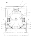
- FIG. 1 is a mold inversion apparatus of the present invention.
- This apparatus is used for reversing a mold that has been molded and transported inside a metal frame in a framed molding line.
- this apparatus performs reversal by alternately repeating forward rotation and reverse rotation of 180 degrees.
- 2 is a fixed roller conveyor for conveying the metal frame 3
- 4 is a reverse roller conveyor arranged in the middle of the fixed roller conveyor 2.
- the arrow Y1 indicates the direction in which the metal frame 3 is conveyed.
- the reversing roller conveyor 4 is for placing and reversing one frame of the metal frame 3, and a pair of ring-shaped reversing tires 5 are provided at both front and rear ends thereof. Since the reverse roller conveyor 4 is fixed to the reverse tire 5, it can be reversed together with the reverse tire 5.
- the metal frame 3 moves from the fixed roller conveyor 2 to the reverse roller conveyor 4 through the center hole of the reverse tire 5.
- the metal frame 3 is carried between the upper and lower flanged rollers 4 a of the pair of reverse roller conveyors 4.
- the pair of inverted tires 5 are supported by two pairs of receiving rollers 6. Unlike the conventional case, these receiving rollers 6 are flangeless rollers, and support two treads on the lower side of the inverted tire 5.
- the receiving roller 6 is a flangeless roller, the reversing tire 5 cannot be positioned by the flange in the metal frame conveying direction Y1 (see FIG. 1). Therefore, in the present invention, as shown in FIGS. 1 and 2, two pairs of side rollers 10 are applied to the side surface of the reverse tire 5 to prevent displacement in the metal frame conveying direction Y1.
- difference in the metal frame conveyance direction Y1 refers to the shift
- the side rollers 10 are disposed on the inner side of the receiving roller 6 (see FIG. 2), and are disposed on both outer sides of the inverted tire 5 in FIG.
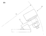
- FIG. 3 is an enlarged side view of the side roller 10.
- the side roller 10 is attached to be inclined by a bracket 15.
- the side roller 10 rotates during normal rotation and reverse rotation of the reverse tire 5.
- the surface of the side roller 10 is an arc surface having a large radius R, and the contact with the side surface of the reverse tire 5 is a point contact. That is, if the receiving roller has a flange, even if the reverse tire 5 rotates during normal rotation and reverse rotation, the flange and the reverse tire 5 cause a difference in rotational speed and are rubbed and worn.
- the receiving roller 6 is made of no flange and the side roller 10 prevents the reverse tire 5 from slipping, the contact between the receiving roller flange and the reverse tire 5 disappears, and the side roller 10 is in point contact. Rubing can be suppressed. With this structure, the progress of wear due to rubbing is suppressed.
- a driving roller 9 is provided on the top of the reversing tire 5.
- One end of the bracket 16 of the driving roller 9 is pivotally supported by the pin 7, and the other end is elastically projected toward the tread surface of the inverted tire 5 by the spring 8. For this reason, the driving roller 9 is always pressed against the tread surface of the reverse tire 5, and the reverse tire 5 can be rotated forward or reverse.
- the drive roller 9 is attached only to the upper part of the reverse tire 5 on one side, but it is also possible to attach the drive roller 9 to the upper parts of both reverse tires 5.
- the reversing roller conveyor 4 Since the reversing roller conveyor 4 is fixed to the reversing tire 5, when the reversing tire 5 is rotated by the drive roller 9, the reversing roller conveyor 4 on which the metal frame 3 is placed is also rotated and the metal frame 3 is turned upside down. be able to.
- a scraper 11 for cleaning the tread of the reversing tire 5 is disposed at an angle of 45 degrees with respect to the vertical line on the outside of the receiving roller 6 (see FIG. 2).
- the tread cleaning scraper 11 includes a square bracket 13 using a square pipe and a square scraper 14 and a spring 12 for pressing the scraper.
- the square scraper 14 is always pressed against the tread surface of the inverted tire 5 by the spring 12 to clean the tread surface.
- the tread cleaning scraper 11 is arranged at an angle of 45 degrees with respect to the vertical line, but this angle can be changed as appropriate. Further, the tread cleaning scraper 11 has been described as accommodating the square scraper 14 inside the square bracket 13, but the shape of the bracket and the scraper is not limited to a square, and may be any shape. The square pipe need not be used to make the bracket.
- the driving roller 9 is rotated forward and backward by the motor 9a.
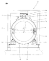
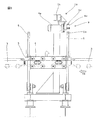
- One end of the bracket 9b of the drive roller 9 is pivotally supported on the frame 1b by a pin 7, and the other end of the bracket 9b is attached to the frame 1b via an air spring 8a. Therefore, the pressing force can be changed by adjusting the internal pressure of the air spring 8a, and the force with which the driving roller 9 presses the tread surface of the reverse tire 5 can be set freely.
- a precise pressure reducing valve 20 is provided in the air piping system to the air spring 8a so that the pressing force of the air spring 8a can be finely adjusted.
- 21 is a filter provided in this air piping system
- 22 is a residual pressure relief valve. That is, compressed air sent from a pneumatic source (not shown) is reduced by the pressure reducing valve 20 and sent to the air spring 8a.
- the drive roller 9 has a structure in which a special rubber 9d (a rubber having a high elastic modulus, friction coefficient and wear resistance, for example, urethane rubber) is baked on the outer periphery of a metal base 9c. If the pressing force of the driving roller 9 is too strong, the special rubber 9d that has been baked will be peeled off. If it is too weak, the driving roller 9 will slip at the time of acceleration / deceleration and reversal, and the reversing tire 5 will wear locally. A malfunction occurs. However, in this embodiment, the driving roller 9 is pressed against the reversing tire 5 by the air spring 8a and the pressing force of the air spring 8a can be finely adjusted. Can be driven, and the conventional special rubber 9d can be prevented from being peeled off, and local wear of the inverted tire 5 can be prevented.
- a special rubber 9d a rubber having a high elastic modulus, friction coefficient and wear resistance, for example, urethane rubber
- the reverse tire 5 has a contact surface with the receiving roller 6 as a replaceable liner 5 a attached from the side surface with a bolt 18.
- the liner 5a is divided into arcs as shown in FIG. 4 (reference numeral 19 in FIG. 4 is a dividing surface).
- the mold reversing device of the present invention even when the conveyance speed and reversing speed of the metal frame are increased as the cycle time is shortened, the consumption of the reversing tire 5 and the receiving roller 6 is reduced. There are advantages that can be done.
Landscapes
- Engineering & Computer Science (AREA)
- Mechanical Engineering (AREA)
- Robotics (AREA)
- Casting Devices For Molds (AREA)
- Moulds For Moulding Plastics Or The Like (AREA)
- Attitude Control For Articles On Conveyors (AREA)
Abstract
金枠の搬送速度や反転速度が高速化した場合にも、反転タイヤや受けローラの消耗を低減することができる鋳型反転装置を提供する。金枠(3)を載せた反転ローラコンベヤ(4)の両側に1対の反転タイヤ(5)を取付け、それらの反転タイヤ(5)の外周面を2対の受けローラ(6)で支持するとともに、一方または双方の反転タイヤ(5)の上部に駆動ローラ(9)を設けた鋳型反転装置である。2対の受けローラ(6)をツバ無しローラとするとともに、2対のサイドローラ(10)を反転タイヤ(5)の側面に当て、金枠搬送方向でのズレを防止した。サイドローラ(10)は反転タイヤ(5)の側面との接触面を円弧面とすることが好ましい。
Description
本発明は、自動鋳造設備の枠付き造型ラインに組み込んで使用される鋳型反転装置に関するものである。
枠付き造型ラインにおいては、金枠の内部に造型される鋳型は、キャビティ面を下向きとして造型され、鋳型反転装置により上下枠とも、キャビティ面を上向きに反転され、上枠は下方から反キャビティ面のサンドカットや湯口掘りを行い、下枠には定盤をセットし、また中子をセットする。次に上枠のみ鋳型反転装置により再反転してキャビティ面を下向きに戻し、キャビティ面が上向きとなっている下枠の上に枠合せされる。このため、従来から特許文献1に示されるような鋳型反転装置が用いられている。
図8と図9に、従来の鋳型反転装置の構造を示す。この鋳型反転装置101は図8に示すように、固定ローラコンベヤ102の途中に配置されるものであり、金枠103を1枠載せて反転させることができる反転ローラコンベヤ104の両側に1対の反転タイヤ105を取付け、その外周面を2対のツバ付きの受けローラ106で受けている。一方または双方の反転タイヤ105の上部には駆動ローラ109が設けられており、反転タイヤ105とともに反転ローラコンベヤ104を反転させる構造である。
従来の枠付き造型ラインはサイクルタイムが長かったため、金枠の搬送速度も低速であり、上記の鋳型反転装置101で特に大きな問題はなかった。しかし、昨今の枠付き造型ラインではサイクルタイムが短縮化され、金枠の搬送速度が高速化している。このため高速搬送の反力により、反転ローラコンベヤ104に取付けた反転タイヤ105が下流側にずれ易く、反転タイヤ105の側面及びツバ付きの受けローラ106のツバの摩耗が速くなるという問題があった。
また、サイクルタイムの短縮に伴い反転速度の高速化も進み、1対の反転タイヤ105及びツバ付きの受けローラ106の踏面の摩耗も速くなるという問題があった。この問題を解消するために、図9に示すように踏面清掃用のスクレーパ111を取付けているが、固定式であるためにスクレーパ111が摩耗すると清掃効果が維持できなくなる。このため頻繁にメンテナンスを行なう必要があった。
しかもこの鋳型反転装置101は、常時その内部に金枠103を積載しているために反転タイヤ105の交換は容易ではなく、反転タイヤ105自体も高価なものであった。さらに、反転タイヤ105の材質変更や熱処理によって耐摩耗性を向上させることも考えられるが、何れも大幅なコストアップの原因となる。
従って本発明の目的は上記した従来の問題点を解決し、サイクルタイムの短縮に伴い金枠の搬送速度や反転速度が高速化した場合にも、反転タイヤや受けローラの消耗を低減することができる鋳型反転装置を提供することである。
上記の課題を解決するためになされた本発明の第1の態様の鋳型反転装置は、金枠を載せた反転ローラコンベヤの両側に1対の反転タイヤを取付け、前記1対の反転タイヤの外周面を2対の受けローラで支持するとともに、一方または双方の前記反転タイヤの上部に駆動ローラを設けた鋳型反転装置であって、前記2対の受けローラをツバ無しローラとするとともに、2対のサイドローラを前記反転タイヤの側面に当てて金枠搬送方向でのズレを防止したことを特徴とするものである。
なお第2の態様のように、前記サイドローラは、前記反転タイヤの側面との接触面を円弧面としたものであることが好ましい。また第3の態様のように、ブラケットの内部にスプリングにより弾発されるスクレーパを収納した踏面清掃用スクレーパを、前記反転タイヤの踏面に接触する位置に配置することが好ましい。
本発明の鋳型反転装置は、1対の反転タイヤの外周面を支持する2対の受けローラをツバ無しローラとするとともに、2対のサイドローラを反転タイヤの側面に当てた構造であるので、従来のように受けローラのツバの摩耗が速くなるという問題を解消することができる。またツバを無くした代わりにサイドローラを設けたので、反転タイヤの金枠搬送方向でのズレも防止することができる。
第2の態様のように、反転タイヤの側面との接触面を円弧面としたサイドローラを用いれば点接触となるので、こすれによる摩耗の進行を抑制することができる。また第3の態様のように、ブラケットの内部にスプリングにより弾発されるスクレーパを収納した踏面清掃用スクレーパを、反転タイヤの踏面に接触する位置に配置すれば、頻繁にメンテナンスを行わなくても反転タイヤの踏面を常に清掃し、その摩耗を防止することができる。
この出願は、日本国で2015年7月28日に出願された特願2015-148727号に基づいており、その内容は本出願の内容として、その一部を形成する。
また、本発明は以下の詳細な説明により更に完全に理解できるであろう。しかしながら、詳細な説明および特定の実施例は、本発明の望ましい実施の形態であり、説明の目的のためにのみ記載されているものである。この詳細な説明から、種々の変更、改変が、当業者にとって明らかだからである。
出願人は、記載された実施の形態のいずれをも公衆に献上する意図はなく、開示された改変、代替案のうち、特許請求の範囲内に文言上含まれないかもしれないものも、均等論下での発明の一部とする。
本明細書あるいは請求の範囲の記載において、名詞及び同様な指示語の使用は、特に指示されない限り、または文脈によって明瞭に否定されない限り、単数および複数の両方を含むものと解釈すべきである。本明細書中で提供されたいずれの例示または例示的な用語(例えば、「等」)の使用も、単に本発明を説明し易くするという意図であるに過ぎず、特に請求の範囲に記載しない限り本発明の範囲に制限を加えるものではない。
また、本発明は以下の詳細な説明により更に完全に理解できるであろう。しかしながら、詳細な説明および特定の実施例は、本発明の望ましい実施の形態であり、説明の目的のためにのみ記載されているものである。この詳細な説明から、種々の変更、改変が、当業者にとって明らかだからである。
出願人は、記載された実施の形態のいずれをも公衆に献上する意図はなく、開示された改変、代替案のうち、特許請求の範囲内に文言上含まれないかもしれないものも、均等論下での発明の一部とする。
本明細書あるいは請求の範囲の記載において、名詞及び同様な指示語の使用は、特に指示されない限り、または文脈によって明瞭に否定されない限り、単数および複数の両方を含むものと解釈すべきである。本明細書中で提供されたいずれの例示または例示的な用語(例えば、「等」)の使用も、単に本発明を説明し易くするという意図であるに過ぎず、特に請求の範囲に記載しない限り本発明の範囲に制限を加えるものではない。
以下に本発明の実施形態を説明する。
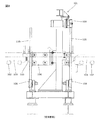
図1において、1は本発明の鋳型反転装置である。この装置は、枠付き造型ラインにおいて、金枠の内部に造型されて搬送されてきた鋳型を反転させるために用いられる。また、この装置は、180度の正転と逆転を交互に繰り返し、反転を行なうものである。2は金枠3を搬送するための固定ローラコンベヤであり、4は固定ローラコンベヤ2の途中に配置された反転ローラコンベヤである。矢印Y1は、金枠3が搬送される方向を示す。
図1において、1は本発明の鋳型反転装置である。この装置は、枠付き造型ラインにおいて、金枠の内部に造型されて搬送されてきた鋳型を反転させるために用いられる。また、この装置は、180度の正転と逆転を交互に繰り返し、反転を行なうものである。2は金枠3を搬送するための固定ローラコンベヤであり、4は固定ローラコンベヤ2の途中に配置された反転ローラコンベヤである。矢印Y1は、金枠3が搬送される方向を示す。
反転ローラコンベヤ4は1枠分の金枠3を載せて反転させるためのものであり、その前後の両端部には一対のリング状の反転タイヤ5が設けられている。反転ローラコンベヤ4は反転タイヤ5に固定されているので、反転タイヤ5とともに反転可能である。なお金枠3は固定ローラコンベヤ2から反転ローラコンベヤ4に、反転タイヤ5の中心孔を通じて移動する。また、金枠3は一対の反転ローラコンベヤ4の上下のツバ付きローラ4a間に搬入される。
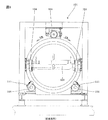
図2に示すように、これらの一対の反転タイヤ5は、2対の受けローラ6によって支持されている。これらの受けローラ6は従来とは異なりツバ無しローラであり、反転タイヤ5の下側の2カ所の踏面を支持している。
また受けローラ6をツバ無しローラとしたため、反転タイヤ5の金枠搬送方向Y1(図1参照)での位置決めをツバによって行うことができない。そこで本発明では、図1、図2に示すように2対のサイドローラ10を反転タイヤ5の側面に当て、金枠搬送方向Y1でのズレを防止している。なお、金枠搬送方向Y1でのズレとは、金枠が搬送される方向へのズレとその逆方向へのズレを指す。サイドローラ10は受けローラ6の内側位置(図2参照)に配置され、図1における反転タイヤ5の両外側(2対であるため、合計4個。片側は図示省略)に配置されている。この構造により、反転タイヤ5の金枠搬送方向Y1でのズレを防止することができる。また、金枠の搬送速度が高速化した場合にも、反転タイヤ5が下流側にずれることを確実に防止することができる。
図3はサイドローラ10の拡大側面図である。図示のようにサイドローラ10はブラケット15により傾斜させて取付けられている。サイドローラ10は、反転タイヤ5の正転および逆転の際には、回転する。サイドローラ10の表面は半径Rが大きい円弧面となっており、反転タイヤ5の側面との接触は点接触となっている。すなわち、受けローラがツバ付きであると、反転タイヤ5の正転および逆転の際に回転しても、ツバと反転タイヤ5とは回転速度に差を生じ、こすれて摩耗する。しかし、受けローラ6をツバなしとして、サイドローラ10で反転タイヤ5のズレを防止すると、受けローラのツバと反転タイヤ5の接触がなくなり、しかも、サイドローラ10は接触が点接触であるので、こすれを抑制できる。この構造により、こすれによる摩耗の進行を抑制している。
反転タイヤ5の上部には、駆動ローラ9が設けられている。駆動ローラ9のブラケット16はその一端がピン7で軸支され、他端はスプリング8により反転タイヤ5の踏面に向けて弾発されている。このため駆動ローラ9は常に反転タイヤ5の踏面に押し付けられ、反転タイヤ5を正転または逆転させることができる。この実施形態では片側の反転タイヤ5の上部だけに駆動ローラ9が取付けられているが、駆動ローラ9を両方の反転タイヤ5の上部に取付けることも可能である。
反転ローラコンベヤ4は反転タイヤ5に固定されているため、駆動ローラ9によって反転タイヤ5が回転されると、金枠3を載せた反転ローラコンベヤ4も回転して金枠3の上下を反転させることができる。
受けローラ6の外側(図2参照)には、反転タイヤ5の踏面清掃用スクレーパ11が、鉛直線に対して45度の角度で配置されている。図2に示すように、踏面清掃用スクレーパ11は角パイプを使用した角形ブラケット13の内部に、角形スクレーパ14と、スクレーパ押圧用のスプリング12とを収納したものである。角形スクレーパ14はスプリング12によって常に反転タイヤ5の踏面に押し付けられ、踏面を清掃する。この構造によって、従来のように頻繁にメンテナンスを行わなくても、反転タイヤ5の踏面に付着した異物を除去することができるので、反転タイヤ5及び受けローラ6の損耗を低減することができる。なお、この実施形態では踏面清掃用スクレーパ11を鉛直線に対して45度の角度で配置したが、この角度は適宜変更することができる。また、踏面清掃用スクレーパ11は角形ブラケット13の内部に角形スクレーパ14を収納しているとして説明したが、ブラケットやスクレーパの形状は角形に限定されず、任意の形状でよい。ブラケットを製作するのに、角パイプを使用しなくてもよい。
ここで、図4および図5を参照して、駆動ローラ9を反転タイヤ5に押しつける力を調整して、反転タイヤ5の局部摩耗を防止することができる鋳型反転装置1aについて説明する。
駆動ローラ9は、モータ9aによって正逆転される。駆動ローラ9のブラケット9bの一端がピン7によってフレーム1bに軸支され、ブラケット9bの他端は空気ばね8aを介してフレーム1bに取付けられている。このため空気ばね8aの内圧を調整することにより押し付け力を変え、駆動ローラ9が反転タイヤ5の踏面を押圧する力を自由に設定することができる。本実施形態では図5に示すように、空気ばね8aへの空気配管系統に精密な減圧弁20を設け、空気ばね8aの押し付け力を繊細に調整可能としている。なお21はこの空気配管系統に設けられたフィルタ、22は残圧排除弁である。すなわち、不図示の空気圧源から送られる圧縮空気を減圧弁20で減圧して空気ばね8aに送る。
駆動ローラ9は図6に示されるように、金属製の基部9cの外周に特殊ゴム9d(弾性係数、摩擦係数および耐摩耗性の高いゴムで、例えば、ウレタンゴム)を焼付けた構造であり、駆動ローラ9の押し付け力が強すぎると、焼付けた特殊ゴム9dが剥離する不具合が発生し、逆に弱すぎると、加減速時及び反転終了時に駆動ローラ9がスリップし、反転タイヤ5が局部摩耗する不具合が発生する。しかし本実施形態では、駆動ローラ9を空気ばね8aにより反転タイヤ5に押し付ける構造とし、かつ空気ばね8aの押し付け力を繊細に調整可能としたので、駆動ローラ9は常に安定した力で反転タイヤ5を駆動させることができ、従来のような特殊ゴム9dの剥離や、反転タイヤ5の局部摩耗を防止することができる。
図7に示すように、反転タイヤ5は、受けローラ6との接触面を、ボルト18で側面から取付けた交換可能なライナ5aとしてある。またこのライナ5aは、図4に示すように円弧状に分割される(図4における符号19が分割面)。これによって、局部摩耗した場合でも反転タイヤ5の全体を交換することなく、金枠3を積んだままでライナ5aのみを交換することができる。従って、反転タイヤ5が局部摩耗した場合にも、局部摩耗した部分のライナ5aを交換することで、部分的に補修が可能となる。
以上に説明したように、本発明の鋳型反転装置によれば、サイクルタイムの短縮に伴い金枠の搬送速度や反転速度が高速化した場合にも、反転タイヤ5や受けローラ6の消耗を低減することができる利点がある。
以下、本明細書および図面に用いた主な符号をまとめて示す。
1、 1a 鋳型反転装置
1b フレーム
2 固定ローラコンベヤ
3 金枠
4 反転ローラコンベヤ
4a ツバ付きローラ
5 反転タイヤ
5a ライナ
6 受けローラ
7 ピン
8 スプリング
8a 空気ばね
9 駆動ローラ
9a モータ
9b ブラケット
9c 基部
9d 特殊ゴム
10 サイドローラ
11 踏面清掃用スクレーパ
12 スプリング
13 角形ブラケット
14 角形スクレーパ
15 ブラケット
16 ブラケット
18 ボルト
19 分割面
20 減圧弁
21 フィルタ
22 残圧排除弁
101 鋳型反転装置
102 固定ローラコンベヤ
103 金枠
104 反転ローラコンベヤ
105 反転タイヤ
106 ツバ付きの受けローラ
109 駆動ローラ
111 踏面清掃用のスクレーパ
1、 1a 鋳型反転装置
1b フレーム
2 固定ローラコンベヤ
3 金枠
4 反転ローラコンベヤ
4a ツバ付きローラ
5 反転タイヤ
5a ライナ
6 受けローラ
7 ピン
8 スプリング
8a 空気ばね
9 駆動ローラ
9a モータ
9b ブラケット
9c 基部
9d 特殊ゴム
10 サイドローラ
11 踏面清掃用スクレーパ
12 スプリング
13 角形ブラケット
14 角形スクレーパ
15 ブラケット
16 ブラケット
18 ボルト
19 分割面
20 減圧弁
21 フィルタ
22 残圧排除弁
101 鋳型反転装置
102 固定ローラコンベヤ
103 金枠
104 反転ローラコンベヤ
105 反転タイヤ
106 ツバ付きの受けローラ
109 駆動ローラ
111 踏面清掃用のスクレーパ
Claims (3)
- 金枠を載せた反転ローラコンベヤの両側に1対の反転タイヤを取付け、前記1対の反転タイヤの外周面を2対の受けローラで支持するとともに、一方または双方の前記反転タイヤの上部に駆動ローラを設けた鋳型反転装置であって、前記2対の受けローラをツバ無しローラとするとともに、2対のサイドローラを前記反転タイヤの側面に当てて金枠搬送方向でのズレを防止したことを特徴とする鋳型反転装置。
- 前記サイドローラは、前記反転タイヤの側面との接触面を円弧面としたことを特徴とする請求項1記載の鋳型反転装置。
- ブラケットの内部にスプリングにより弾発されるスクレーパを収納した踏面清掃用スクレーパを、前記反転タイヤの踏面に接触する位置に配置したことを特徴とする請求項1または2記載の鋳型反転装置。
Priority Applications (4)
| Application Number | Priority Date | Filing Date | Title |
|---|---|---|---|
| US15/575,106 US10486340B2 (en) | 2015-07-28 | 2016-05-25 | Device for turning over molds |
| CN201680025548.9A CN107530768B (zh) | 2015-07-28 | 2016-05-25 | 铸模翻转装置 |
| MX2017015408A MX2017015408A (es) | 2015-07-28 | 2016-05-25 | Dispositivo para hacer girar moldes. |
| EP16830145.5A EP3330019A4 (en) | 2015-07-28 | 2016-05-25 | FORM REVERSAL DEVICE |
Applications Claiming Priority (2)
| Application Number | Priority Date | Filing Date | Title |
|---|---|---|---|
| JP2015148727A JP6406152B2 (ja) | 2015-07-28 | 2015-07-28 | 鋳型反転装置 |
| JP2015-148727 | 2015-07-28 |
Publications (1)
| Publication Number | Publication Date |
|---|---|
| WO2017018040A1 true WO2017018040A1 (ja) | 2017-02-02 |
Family
ID=57885597
Family Applications (1)
| Application Number | Title | Priority Date | Filing Date |
|---|---|---|---|
| PCT/JP2016/065397 Ceased WO2017018040A1 (ja) | 2015-07-28 | 2016-05-25 | 鋳型反転装置 |
Country Status (6)
| Country | Link |
|---|---|
| US (1) | US10486340B2 (ja) |
| EP (1) | EP3330019A4 (ja) |
| JP (1) | JP6406152B2 (ja) |
| CN (1) | CN107530768B (ja) |
| MX (1) | MX2017015408A (ja) |
| WO (1) | WO2017018040A1 (ja) |
Cited By (2)
| Publication number | Priority date | Publication date | Assignee | Title |
|---|---|---|---|---|
| CN109968440A (zh) * | 2019-04-30 | 2019-07-05 | 江苏富技腾机电科技有限公司 | 一种具有翻转功能的切割装置 |
| JP2024501856A (ja) * | 2020-12-29 | 2024-01-16 | バーテックス ファーマシューティカルズ インコーポレイテッド | ベータ細胞の分化の向上 |
Families Citing this family (3)
| Publication number | Priority date | Publication date | Assignee | Title |
|---|---|---|---|---|
| CN110202122B (zh) * | 2019-06-21 | 2023-06-20 | 浙江省军工集团股份有限公司 | 一种翻箱机 |
| CN111318941B (zh) * | 2020-03-31 | 2024-06-18 | 巩义市力峰机电科技有限公司 | 摩托车鼓式刹车片生产线 |
| CN112059154B (zh) * | 2020-08-07 | 2021-10-29 | 安徽埃斯克制泵有限公司 | 一种自吸泵泵体砂型铸造脱模装置 |
Citations (1)
| Publication number | Priority date | Publication date | Assignee | Title |
|---|---|---|---|---|
| JP2010023058A (ja) * | 2008-07-16 | 2010-02-04 | Sintokogio Ltd | レール可倒式鋳枠反転機 |
Family Cites Families (12)
| Publication number | Priority date | Publication date | Assignee | Title |
|---|---|---|---|---|
| DE103824C (ja) | ||||
| US3114332A (en) * | 1960-05-16 | 1963-12-17 | Walt Disney Prod | Bobsled amusement ride |
| JPS4612619Y1 (ja) | 1967-12-06 | 1971-05-04 | ||
| DD103824A1 (ja) * | 1973-04-02 | 1974-02-12 | ||
| JPS5335539Y2 (ja) * | 1975-03-17 | 1978-08-31 | ||
| JPH11290993A (ja) * | 1998-04-10 | 1999-10-26 | Sintokogio Ltd | 鋳枠反転送出し方法 |
| CN2845960Y (zh) | 2005-12-15 | 2006-12-13 | 天津市亨特尔机电发展有限公司 | 砂箱摩擦式翻箱装置 |
| JP2007301608A (ja) | 2006-05-12 | 2007-11-22 | Sintokogio Ltd | 鋳型搬送設備および該鋳型搬送設備を用いる鋳型造型設備 |
| JP4711198B2 (ja) | 2008-03-07 | 2011-06-29 | 新東工業株式会社 | 鋳型反転移載装置 |
| CN102019364A (zh) | 2009-09-14 | 2011-04-20 | 苏州苏铸成套装备制造有限公司 | 一种砂箱翻箱机构 |
| CN202639243U (zh) | 2012-05-14 | 2013-01-02 | 辽阳市富祥曲轴有限公司 | 自动翻箱机 |
| CN104226967A (zh) | 2014-08-20 | 2014-12-24 | 安徽新宁装备股份有限公司 | 一种翻模出球分向机 |
-
2015
- 2015-07-28 JP JP2015148727A patent/JP6406152B2/ja active Active
-
2016
- 2016-05-25 CN CN201680025548.9A patent/CN107530768B/zh active Active
- 2016-05-25 US US15/575,106 patent/US10486340B2/en active Active
- 2016-05-25 MX MX2017015408A patent/MX2017015408A/es unknown
- 2016-05-25 EP EP16830145.5A patent/EP3330019A4/en not_active Withdrawn
- 2016-05-25 WO PCT/JP2016/065397 patent/WO2017018040A1/ja not_active Ceased
Patent Citations (1)
| Publication number | Priority date | Publication date | Assignee | Title |
|---|---|---|---|---|
| JP2010023058A (ja) * | 2008-07-16 | 2010-02-04 | Sintokogio Ltd | レール可倒式鋳枠反転機 |
Non-Patent Citations (1)
| Title |
|---|
| See also references of EP3330019A4 * |
Cited By (3)
| Publication number | Priority date | Publication date | Assignee | Title |
|---|---|---|---|---|
| CN109968440A (zh) * | 2019-04-30 | 2019-07-05 | 江苏富技腾机电科技有限公司 | 一种具有翻转功能的切割装置 |
| CN109968440B (zh) * | 2019-04-30 | 2024-04-23 | 江苏富技腾机电科技有限公司 | 一种具有翻转功能的切割装置 |
| JP2024501856A (ja) * | 2020-12-29 | 2024-01-16 | バーテックス ファーマシューティカルズ インコーポレイテッド | ベータ細胞の分化の向上 |
Also Published As
| Publication number | Publication date |
|---|---|
| CN107530768B (zh) | 2019-05-07 |
| US20180154554A1 (en) | 2018-06-07 |
| JP2017024067A (ja) | 2017-02-02 |
| JP6406152B2 (ja) | 2018-10-17 |
| CN107530768A (zh) | 2018-01-02 |
| EP3330019A1 (en) | 2018-06-06 |
| US10486340B2 (en) | 2019-11-26 |
| MX2017015408A (es) | 2018-03-01 |
| EP3330019A4 (en) | 2019-03-06 |
Similar Documents
| Publication | Publication Date | Title |
|---|---|---|
| WO2017018040A1 (ja) | 鋳型反転装置 | |
| US10500894B2 (en) | Robot cleaner | |
| CN204416398U (zh) | 一种可自动清扫皮带粘料的带式运输机 | |
| JP6409707B2 (ja) | 鋳型反転装置 | |
| JP5149189B2 (ja) | タイヤ/ホイールビード混入物除去装置 | |
| JP2018008292A (ja) | 鋳型反転装置 | |
| JP6454220B2 (ja) | グリーンタイヤ運搬・保持装置 | |
| KR20160022441A (ko) | 대면적 기판의 반송장치 | |
| JP4644861B2 (ja) | 負圧などの吸着手段により表面に吸着する移動台車 | |
| CN112374055B (zh) | 回转式垂直提升机及提升方法 | |
| CN206255555U (zh) | 皮带运输机的纠偏装置及皮带运输机 | |
| JP6663705B2 (ja) | タイヤモールド | |
| JP6280374B2 (ja) | ゴムストリップの押付け装置 | |
| CN219383744U (zh) | 一种物流传输机 | |
| KR101299861B1 (ko) | 벨트 컨베이어 클리닝 장치 | |
| CN224131445U (zh) | 茶叶包装自动翻转对接装置 | |
| CN204382684U (zh) | 轮胎硫化机的辊道翻胎装置 | |
| KR100782604B1 (ko) | 컨베이어용 임팩트 롤러 휠 | |
| CN218908792U (zh) | 一种轮胎输送机 | |
| JP4730953B2 (ja) | タイヤ成型用金型の洗浄方法 | |
| CN211944997U (zh) | 一种贮叶柜往复布料车的输送装置 | |
| CN208120034U (zh) | 推头及输送机构 | |
| JPH07125662A (ja) | 走行装置 | |
| CN209621981U (zh) | 一种用于皮带传动中的纠偏装置 | |
| CN120981408A (zh) | 搬送用旋转部件、输送装置和滚子部件 |
Legal Events
| Date | Code | Title | Description |
|---|---|---|---|
| 121 | Ep: the epo has been informed by wipo that ep was designated in this application |
Ref document number: 16830145 Country of ref document: EP Kind code of ref document: A1 |
|
| REEP | Request for entry into the european phase |
Ref document number: 2016830145 Country of ref document: EP |
|
| WWE | Wipo information: entry into national phase |
Ref document number: 15575106 Country of ref document: US |
|
| WWE | Wipo information: entry into national phase |
Ref document number: MX/A/2017/015408 Country of ref document: MX |
|
| NENP | Non-entry into the national phase |
Ref country code: DE |