WO2017018061A1 - 水蒸気観測システム - Google Patents
水蒸気観測システム Download PDFInfo
- Publication number
- WO2017018061A1 WO2017018061A1 PCT/JP2016/066984 JP2016066984W WO2017018061A1 WO 2017018061 A1 WO2017018061 A1 WO 2017018061A1 JP 2016066984 W JP2016066984 W JP 2016066984W WO 2017018061 A1 WO2017018061 A1 WO 2017018061A1
- Authority
- WO
- WIPO (PCT)
- Prior art keywords
- water vapor
- wave
- observation system
- transmission
- unit
- Prior art date
- Legal status (The legal status is an assumption and is not a legal conclusion. Google has not performed a legal analysis and makes no representation as to the accuracy of the status listed.)
- Ceased
Links
Images


Classifications
-
- G—PHYSICS
- G01—MEASURING; TESTING
- G01W—METEOROLOGY
- G01W1/00—Meteorology
- G01W1/14—Rainfall or precipitation gauges
-
- G—PHYSICS
- G01—MEASURING; TESTING
- G01N—INVESTIGATING OR ANALYSING MATERIALS BY DETERMINING THEIR CHEMICAL OR PHYSICAL PROPERTIES
- G01N22/00—Investigating or analysing materials by the use of microwaves or radio waves, i.e. electromagnetic waves with a wavelength of one millimetre or more
- G01N22/04—Investigating moisture content
-
- G—PHYSICS
- G01—MEASURING; TESTING
- G01S—RADIO DIRECTION-FINDING; RADIO NAVIGATION; DETERMINING DISTANCE OR VELOCITY BY USE OF RADIO WAVES; LOCATING OR PRESENCE-DETECTING BY USE OF THE REFLECTION OR RERADIATION OF RADIO WAVES; ANALOGOUS ARRANGEMENTS USING OTHER WAVES
- G01S13/00—Systems using the reflection or reradiation of radio waves, e.g. radar systems; Analogous systems using reflection or reradiation of waves whose nature or wavelength is irrelevant or unspecified
- G01S13/003—Bistatic radar systems; Multistatic radar systems
-
- G—PHYSICS
- G01—MEASURING; TESTING
- G01S—RADIO DIRECTION-FINDING; RADIO NAVIGATION; DETERMINING DISTANCE OR VELOCITY BY USE OF RADIO WAVES; LOCATING OR PRESENCE-DETECTING BY USE OF THE REFLECTION OR RERADIATION OF RADIO WAVES; ANALOGOUS ARRANGEMENTS USING OTHER WAVES
- G01S13/00—Systems using the reflection or reradiation of radio waves, e.g. radar systems; Analogous systems using reflection or reradiation of waves whose nature or wavelength is irrelevant or unspecified
- G01S13/88—Radar or analogous systems specially adapted for specific applications
- G01S13/95—Radar or analogous systems specially adapted for specific applications for meteorological use
- G01S13/951—Radar or analogous systems specially adapted for specific applications for meteorological use ground based
-
- G—PHYSICS
- G01—MEASURING; TESTING
- G01W—METEOROLOGY
- G01W1/00—Meteorology
-
- Y—GENERAL TAGGING OF NEW TECHNOLOGICAL DEVELOPMENTS; GENERAL TAGGING OF CROSS-SECTIONAL TECHNOLOGIES SPANNING OVER SEVERAL SECTIONS OF THE IPC; TECHNICAL SUBJECTS COVERED BY FORMER USPC CROSS-REFERENCE ART COLLECTIONS [XRACs] AND DIGESTS
- Y02—TECHNOLOGIES OR APPLICATIONS FOR MITIGATION OR ADAPTATION AGAINST CLIMATE CHANGE
- Y02A—TECHNOLOGIES FOR ADAPTATION TO CLIMATE CHANGE
- Y02A90/00—Technologies having an indirect contribution to adaptation to climate change
- Y02A90/10—Information and communication technologies [ICT] supporting adaptation to climate change, e.g. for weather forecasting or climate simulation
Definitions
- the present invention relates to a water vapor observation system for observing water vapor contained in the atmosphere.
- Non-Patent Document 1 discloses a system for observing the amount of water vapor contained in the atmosphere using a passive radar. In this system, the amount of water vapor at a desired point is measured by determining the propagation delay of a terrestrial digital broadcast wave transmitted from a radio tower.
- the present invention is for solving the above-described problems, and an object of the present invention is to provide a water vapor observation system capable of observing water vapor regardless of the state of an external system.
- a water vapor observation system is a water vapor observation system that observes water vapor contained in the atmosphere, and a transmission unit that transmits a transmission wave;
- the first wave receiving unit that is arranged at a position different from the wave transmitting unit and receives the transmission wave as the first received wave is different from the wave transmitting unit and the first wave receiving unit.
- a second receiving unit as a receiving unit that is disposed at a position and receives the transmitted wave as a second received wave, and the first received wave passes based on the first received wave and the second received wave.
- a position reference relative water vapor amount calculation unit that calculates, as a position reference relative water vapor amount, the amount of water vapor contained in the region through which the second received wave has passed with reference to the amount of water vapor contained in the region. Yes.
- the water vapor observation system includes a plurality of the second wave receiving units arranged at different positions.
- the transmitting unit, the first receiving unit, and the plurality of the second receiving units are arranged so that a straight line connecting them is formed in a lattice shape when viewed from above. Yes.
- the water vapor observation system includes a wave transmitting / receiving unit in which the wave transmitting unit and the wave receiving unit are integrated.
- the water vapor observation system includes a transponder that is provided as the transmission / reception unit and transmits the transmission wave in response to the transmission wave from the transmission unit.
- one of the wave transmitting unit and the wave receiving unit is arranged above the other.
- the position reference relative water vapor amount calculation unit includes a first attenuation amount obtained by subtracting an echo level of the first reception wave from a level of the transmission wave, and the second reception wave from the level of the transmission wave.
- the position reference relative water vapor amount is calculated based on the second attenuation amount obtained by subtracting the echo level.
- a water vapor observation system for observing water vapor contained in the atmosphere, and includes a first transmission wave and the first transmission wave.
- a receiving unit that receives the wave as a wave or a position different from the transmitting unit, and receives the first transmission wave and the second transmission wave as the first reception wave and the second reception wave, respectively.
- the second transmission wave is transmitted on the basis of the amount of water vapor contained in the region through which the water has passed.
- a time reference relative water vapor amount calculation unit that calculates the amount of water vapor contained in the region through which the second transmission wave has passed from when the wave is received by the wave receiving unit as a time reference relative water vapor amount, I have.
- the water vapor observation system is a plurality of the wave receiving units, each of which is arranged at a position different from each other and at a position different from the wave transmission unit, and the first transmission wave And a plurality of the wave receiving sections for receiving each of the second transmission waves as the first reception wave and the second reception wave, respectively.
- the transmitting unit and the plurality of receiving units are arranged so that straight lines connecting them to each other form a lattice shape when viewed from above.
- one of the wave transmitting unit and the wave receiving unit is arranged above the other.
- the time-based relative water vapor amount calculation unit calculates the first attenuation amount obtained by subtracting the echo level of the first reception wave from the level of the first transmission wave, and the level of the second transmission wave.
- the time reference relative water vapor amount is calculated based on the second attenuation amount obtained by subtracting the echo level of the second received wave.
- a water vapor observation system is a water vapor observation system that observes water vapor contained in the atmosphere, and includes a transmission unit that transmits a transmission wave; A receiving unit that receives a reflected wave that is reflected from a fixed object as a received wave, or a receiving unit that is disposed at a position different from the transmitting unit and receives the transmitted wave as a received wave. And a relative water vapor amount calculation unit that calculates a relative water vapor amount that is a relative value of water vapor based on a reference water vapor amount to be compared based on a received wave received by the wave receiving unit. ing.
- the water vapor observation system is disposed at a position different from the wave transmission unit, and receives the transmission wave as a first reception wave as the first wave reception unit;
- a second receiving section as the receiving section that is disposed at a position different from the transmitting section and the first receiving section and receives the transmission wave as a second received wave, and the relative water vapor amount
- the calculation unit is included in the region through which the second received wave has passed based on the amount of water vapor contained in the region through which the first received wave has passed based on the first received wave and the second received wave.
- the position reference relative water vapor amount calculation unit calculates a position reference relative water vapor amount which is the amount of water vapor as the relative water vapor amount.
- the position-based relative water vapor amount calculation unit includes a first attenuation amount obtained by subtracting an echo level of the first reception wave from a level of the transmission wave, and the second reception from the transmission wave level.
- the position reference relative water vapor amount is calculated based on the second attenuation amount obtained by subtracting the wave echo level.
- the transmission unit transmits a first transmission wave and a second transmission wave transmitted later than the first transmission wave as the transmission wave
- the reception unit is Receiving each of the reflected waves that come back as a result of reflection of each of the first transmission wave and the second transmission wave as a first reception wave and a second reception wave as the reception wave, or Disposed at a position different from the transmission unit, receiving each of the first transmission wave and the second transmission wave as the first reception wave and the second reception wave as the reception wave, and the relative water vapor amount Based on the first received wave and the second received wave, the calculation unit passes the first transmitted wave between the time when the first transmitted wave is transmitted and the time when the received wave is received by the receiving unit.
- the receiving unit Based on the amount of water vapor contained in the region, the receiving unit receives the second transmission wave after the second transmission wave is transmitted.
- the time reference relative water vapor content second transmission wave is the amount of water vapor contained in the region that has passed until the a time reference relative steam quantity calculating unit that calculates, as the relative amount of water vapor.
- the time-based relative water vapor amount calculation unit is based on a first attenuation amount obtained by subtracting an echo level of the first reception wave from a level of the first transmission wave, and a level of the second transmission wave.
- the time reference relative water vapor amount is calculated based on the second attenuation amount obtained by subtracting the echo level of the second received wave.
- the water vapor observation system further includes a display unit for displaying an index of the position reference relative water vapor amount calculated by the position reference relative water vapor amount calculation unit.
- the display unit displays the position reference relative water vapor amount distribution calculated by the position reference relative water vapor amount calculation unit as the index.
- the water vapor observation system further includes a display unit for displaying an index of the time reference relative water vapor amount calculated by the time reference relative water vapor amount calculation unit.
- the display unit displays the distribution of the time reference relative water vapor amount calculated by the time reference relative water vapor amount calculation unit as the index.
- FIG. 3 is a diagram schematically showing a positional relationship between a wave transmission unit and a wave reception unit, a water vapor observation region Z, and each area Z1 to Z8. It is a block diagram which shows the structure of the calculation process part shown in FIG. It is a graph for demonstrating the calculation result obtained by the process performed by the calculation process part shown in FIG.
- FIG. 1 It is a schematic diagram which shows the structure of the water vapor
- (A) to (C) are diagrams each schematically showing a positional relationship between a transmission unit and a reception unit included in a water vapor observation system according to a modification. It is a schematic diagram which shows the structure of the water vapor
- FIG. 1 is a schematic diagram showing a configuration of a water vapor observation system 1 according to an embodiment of the present invention.
- FIG. 2 is a block diagram illustrating the configuration of the transmission unit Tx and the reception unit Rx.
- FIG. 2A is a block diagram illustrating the configuration of the transmission unit Tx, and
- FIG. It is a block diagram which shows the structure of part Rx.
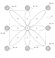
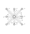
- FIG. 3 shows a wave transmitting section Tx and a wave receiving section Rx, a region where water vapor can be observed by the water vapor observation system 1 shown in FIG. 1 (water vapor observation region Z), and each area Z1 included in the water vapor observation region Z. It is a figure which shows typically the positional relationship with -Z8.
- the water vapor observation system 1 shown in FIG. 1 refers to the relative value of the water vapor amount in each of the areas Z2 to Z8 in the water vapor observation region Z, specifically, a predetermined area (in the present embodiment).
- the water vapor amount (relative water vapor amount, position-based relative water vapor amount) in the other areas Z2 to Z8 based on the water vapor amount in the area Z1) can be calculated.
- the water vapor observation system 1 is configured to be able to calculate the distribution of the relative water vapor amount in the water vapor observation region Z.
- region Z is an area
- the water vapor observation system 1 includes a transmission unit Tx, a plurality of reception units Rx (Rx 1 to Rx 8 ), a calculation processing unit 10, and a display unit 9.
- the receiving unit Rx 1 is provided as a first receiving unit, and the receiving units Rx 2 to Rx 8 are provided as second receiving units.
- the wave transmitting unit Tx and the wave receiving unit Rx have a lattice shape in which straight lines connecting the wave transmitting unit Tx and the plurality of wave receiving units Rx are viewed from above.
- the wave transmitting part Tx is arranged at the center of the water vapor observation region Z, and each wave receiving part Rx is arranged around the wave transmitting part Tx.
- the positional relationship between the transmitting unit Tx and the receiving unit Rx is not limited to this and may be other positional relationships.
- the transmission unit Tx includes a transmission antenna 2, a signal generator 3, and a transmitter 4.
- the transmitting antenna 2 is a radar antenna capable of transmitting a highly directional radio wave (transmitted wave). For example, a radio wave having a frequency of 22 GHz is transmitted from the transmitting antenna 2. When the radio wave transmitted from the transmitting antenna 2 travels in the distance direction (radial direction centered on the transmitting antenna 2), the radio wave is attenuated by water vapor existing in the middle thereof, and is received as a received wave. The signal is received by the Rx receiving antenna 5.
- the transmitting antenna 2 is configured to be able to rotate 360 ° on a horizontal plane.
- the transmitting antenna 2 is configured to transmit radio waves while changing the direction of radio wave transmission (changing the antenna angle) at a constant rotational speed. Thereby, the transmitting antenna 2 transmits a transmission wave to each receiving unit Rx at a predetermined time interval T.
- the time interval T corresponds to the time required for the transmitting antenna 2 to make one rotation.
- the signal generator 3 generates a transmission signal that is the basis of the radio wave transmitted from the transmission antenna 2. This transmission signal is amplified by the transmitter 4 and then output to the transmitting antenna 2.
- Each receiving section Rx has a receiving antenna 5 and a receiver 6.
- the receiving antenna 5 is configured to receive the radio wave from the transmitting antenna 2.
- the receiving antenna 5 is a radar antenna that can receive a highly directional radio wave (received wave).
- the receiving antenna 5 is set so that the received beam is directed to the transmitting antenna 2.
- Each receiving antenna 5 receives a received wave at a predetermined time interval T. Received waves received by the receiving antenna 5 at predetermined time intervals T are sequentially output to the receiver 6 as received signals.
- the radio wave received by the receiving antenna 5 of the first receiving unit Rx 1 is received by the receiving antenna 5 of the first receiving wave and the second receiving units Rx 2 to Rx 8.
- the received radio wave may be referred to as a second received wave.
- the receiver 6 amplifies the received signal output from the receiving antenna 5 and A / D converts the amplified received signal. Thereafter, the receiver 6 transmits the received signal converted into the digital signal to the calculation processing unit 10.
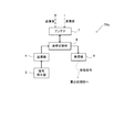
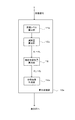
- FIG. 4 is a block diagram showing a configuration of the calculation processing unit 10 shown in FIG.
- FIG. 5 is a graph for explaining the calculation results obtained by the processing performed by the calculation processing unit 10.
- the calculation processing unit 10 includes a reception level calculation unit 11, an attenuation amount calculation unit 12, a relative water vapor amount calculation unit 13 (position reference relative water vapor amount calculation unit), and a distribution image generation unit 14.
- the calculation processing unit 10 includes, for example, a processor (CPU, FPGA, etc.) not shown and a device such as a memory.
- the CPU reads the program from the memory and executes it, whereby the calculation processing unit 10 is changed to a reception level calculation unit 11, an attenuation amount calculation unit 12, a relative water vapor amount calculation unit 13 (position reference relative water vapor amount calculation unit), and It can function as the distribution image generation unit 14.
- the reception level calculation unit 11 calculates the echo level of the reception wave sequentially received by each of the reception units Rx 1 to Rx 8 based on the reception signal transmitted from each reception unit Rx.
- the attenuation amount calculation unit 12 transmits the level TL of the transmission wave transmitted from the transmission unit Tx and the echo level RL of the reception wave received by each of the reception units Rx 1 to Rx 8. Based on 1 to RL 8 , the attenuation amount A (A 1 to A 8 ) of the radio wave that has passed through each of the areas Z1 to Z8 is calculated. Specifically, the attenuation amount calculation unit 12 subtracts the echo level of the reception wave received by each of the reception units Rx 1 to Rx 8 from the level TL of the transmission wave transmitted from the transmission unit Tx, The subtraction value is calculated as attenuation amounts A 1 to A 8 .
- the attenuation amount calculation unit 12 sequentially calculates the attenuation amounts A 1 to A 8 at predetermined time intervals T.
- the value obtained by subtracting the transmission wave level TL by the echo level RL 1 of the first reception wave is calculated as the first attenuation amount A 1 .
- the value obtained by subtracting the transmission wave level TL by the echo levels RL 2 to RL 8 of the second reception wave is calculated as the second attenuation amounts A 2 to A 8 .
- the water vapor amount (relative water vapor amount C 2 to C 8 ) in each of the areas Z2 to Z8 is calculated.
- the relative amount of water vapor calculation unit 13, the attenuation A 2 ⁇ A 8 in the areas Z2 ⁇ Z8, obtain the subtraction value B 2 ⁇ B 8 by subtracting the attenuation amount A 1 in the reference area Z1.
- the relative water vapor amount calculation unit 13 multiplies each of the subtraction values B 2 to B 8 obtained in this way by a predetermined coefficient to obtain the relative water vapor amounts C 2 to C 8 in the areas Z2 to Z8. calculate.
- the relative water vapor amount calculation unit 13 sequentially calculates the relative water vapor amounts C 2 to C 8 at predetermined time intervals T.
- Attenuation amounts A 1 to A 8 of radio waves propagating through the areas Z 1 to Z 8 refer to the water vapor-induced attenuation amounts Vap 1 to Vap 1 to Vap 1 caused by the amount of water vapor contained in the path through which the radio waves propagated, with reference to FIG. This can be divided into Vap 8 and other factor attenuation amounts Oth 1 to Oth 8 caused by other factors.
- areas Z1 ⁇ Z8 are the area relatively close to each other, other factors attenuation Oth 1 ⁇ Oth 8 can be considered to be substantially the same regardless of the areas Z 1 ⁇ Z 8.
- the subtraction values B 2 to B 8 obtained by subtracting the attenuation amount A 1 from the attenuation amounts A 2 to A 8 are values corresponding to the relative water vapor amounts C 2 to C 8 . Therefore, by multiplying the subtraction values B 2 to B 8 by a predetermined constant, the relative water vapor amounts C 2 to C 8 in the areas Z2 to Z8 can be obtained. Note that, for example, a constant obtained in advance by an experiment or the like is used as the constant multiplied by the subtraction values B 2 to B 8 .
- the distribution image generation unit 14 generates a distribution image of the relative water vapor amounts C 2 to C 8 based on the relative water vapor amounts C 2 to C 8 of the areas Z2 to Z8 calculated by the relative water vapor amount calculation unit 13.
- the distribution image generation unit 14 sequentially generates distribution images of the relative water vapor amounts C 2 to C 8 at predetermined time intervals T.
- the display unit 9 displays a distribution image of the relative water vapor amounts C 2 to C 8 generated by the distribution image generation unit 14.
- the distribution image displayed on the display unit 9 is updated from time to time with the most recently generated distribution image.
- the color tones corresponding to the relative water vapor amounts C 2 to C 8 of the areas Z 2 to Z 8 are displayed over the map displayed on the display unit 9. For example, as an example, an area with a large relative water vapor amount is displayed in red, and an area with a small relative water vapor amount is displayed in blue. Thereby, the user can grasp the relative water vapor amounts C 2 to C 8 in the areas Z2 to Z8.
- the radio wave transmitted from the transmission unit Tx is received by the reception unit Rx disposed at a position different from the transmission unit Tx.
- the radio wave received by the wave receiving unit Rx includes information on water vapor contained in the propagation path of the radio wave. Therefore, each area Z2 based on the reference water vapor amount (the water vapor amount contained in the area Z1 in the case of the present embodiment) is analyzed by analyzing the radio wave received by the wave receiving unit Rx as in the present embodiment.
- Relative water vapor amounts C 2 to C 8 which are relative values of water vapor contained in .about.Z8, can be calculated.
- the relative water vapor amounts C 2 to C 8 are calculated based on the radio wave transmitted by the system 1. Therefore, for example, water vapor can be observed regardless of the situation of other systems as compared with the case where the water vapor amount is calculated based on the propagation delay of the terrestrial digital broadcast wave transmitted from the radio tower.
- the water vapor observation system 1 it is possible to provide a water vapor observation system capable of observing water vapor regardless of the state of the external system.
- the wave transmitting unit Tx, the first wave receiving unit Rx 1 , and the second wave receiving units Rx 2 to Rx 8 are arranged at different positions.
- the first received wave is generated based on the received wave received by the second receiving units Rx 2 to Rx 8 and the received wave received by the first receiving unit Rx 1.
- Relative water vapor amounts C 2 to C 8 which are amounts of water vapor contained in the regions (each area Z2 to Z8) through which the second received wave has passed, based on the amount of water vapor contained in the region (reference area Z1) that has passed. Can be calculated. That is, according to the water vapor observation system 1, the water vapor amount in other areas can be calculated based on the water vapor amount in the reference area Z1).
- the distribution of the relative water vapor amount in the water vapor observation region Z can be calculated by providing the plurality of second receiving portions Rx 2 to Rx 8 .
- the wave transmitting unit Tx and the plurality of wave receiving units Rx 1 to Rx 8 are arranged so that the straight line connecting them to each other forms a lattice shape when viewed from above.
- the areas Z1 to Z8 included in the water vapor observation region Z can be set uniformly in the water vapor observation region Z, so that the relative water vapor amount at each point in the water vapor observation region Z can be uniformly distributed. It can be calculated.
- the amount of attenuation caused by factors other than water vapor included in each of the attenuation amounts A 1 to A 8 can be offset, so that the relative water vapor amounts C 2 to C 8 can be calculated appropriately.
- a radio wave having a frequency of 22 GHz is used in the water vapor observation system 1.
- a radio wave having a frequency of 22 GHz is greatly attenuated by water vapor as described above. Therefore, by using a radio wave having a frequency of 22 GHz as in this embodiment, the ratio of the water vapor-induced attenuation amounts Vap 1 to Vap 8 to the other factor attenuation amounts Oth 1 to Oth 8 can be increased with reference to FIG. .
- the difference between the other factor attenuation amounts Oth 1 to Oth 8 generated when subtracting the first attenuation amount A 1 from the second attenuation amounts A 2 to A 8 is less likely to affect the relative water vapor amounts C 2 to C 8. Therefore, the relative water vapor amounts C 2 to C 8 can be calculated more accurately.
- the position reference relative water vapor amount at each point is indicated on the display unit 9 of the water vapor observation system 1 by a color tone as an index representing the water vapor amount.
- the display unit 9 of the water vapor observation system 1 displays a position reference relative water vapor distribution image. Thereby, the user can grasp the distribution of the position reference relative water vapor amount in the water vapor observation region Z.
- FIG. 6 is a schematic diagram showing a configuration of a water vapor observation system 1a according to a modification.
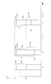
- FIG. 7 is a block diagram showing a configuration of the wave transmitting / receiving unit TRx of the water vapor observation system 1a.
- the water vapor observation system 1 including one transmission unit Tx and a plurality of reception units Rx is configured, but the present invention is not limited to this.
- a water vapor observation system 1 having a plurality of wave transmitting / receiving units TRx may be configured.
- portions different from the above embodiment will be mainly described, and descriptions of other portions will be omitted.
- the water vapor observation system 1a includes a plurality of (in the case of the present embodiment, nine) transmission / reception units TRx, a calculation processing unit 10, and a display unit 9.
- the plurality of transmission / reception units TRx are arranged such that straight lines connecting the plurality of transmission / reception units TRx are in a lattice shape when viewed from above.
- the transmission / reception unit TRx includes an antenna 7, a transmission / reception switching unit 8, a signal generator 3, a transmitter 4, and a receiver 6. Since the signal generator 3, the transmitter 4, and the receiver 6 are the same as those in the above-described embodiment, description thereof is omitted.
- the antenna 7 is a radar antenna capable of both transmitting and receiving radio waves.
- Each antenna 7 is rotatable and configured to repeatedly transmit radio waves to other antennas 7 and receive radio waves from other antennas 7.
- Each antenna 7 transmits a radio wave having a frequency of 22 GHz, as in the case of the above-described embodiment. When this radio wave travels toward another antenna 7, it is attenuated by water vapor existing in the middle of the radio wave, and is received by the other antenna 7 as a received wave. The received wave is output to the receiver 6 as a received signal.
- the transmission / reception switching unit 8 switches to a connection in which a transmission signal is transmitted from the transmitter 4 to the antenna 7 during transmission.
- the transmission / reception switching unit 8 switches to a connection in which a reception signal from the antenna 7 is transmitted to the receiver 6 at the time of wave reception.
- the reception signals obtained from the reception waves received by the transmission / reception units TRx are used for the areas Z2 to Z8.
- the relative water vapor amounts C 2 to C 8 are calculated, and a distribution image of the relative water vapor amounts C 2 to C 8 is generated.
- the water vapor observation system 1a can provide a water vapor observation system that can observe water vapor regardless of the state of the external system, as in the case of the above embodiment.
- the relative water vapor amounts C 2 to C 8 can be calculated more accurately. Specifically, for a pair of opposing transmission / reception units TRx, a relative water vapor amount calculated based on a transmission wave from one to the other, and a relative water vapor amount calculated based on a transmission wave from the other to one Can be calculated more accurately.
- the water vapor distribution is calculated with higher resolution. be able to.
- FIG. 8 is a schematic diagram showing a configuration of a water vapor observation system 1b according to a modification.
- the water vapor observation system 1 including one transmission unit Tx and a plurality of reception units Rx is configured, but the present invention is not limited to this.
- the receiving unit Rx in the above embodiment may be replaced with a transponder TP (see FIG. 8). Even with such a configuration, it is possible to provide a water vapor observation system capable of observing water vapor regardless of the state of the external system, as in the case of the above-described embodiment.
- the relative water vapor amounts C 2 to C 8 can be calculated more accurately.
- the relative water vapor amount calculated based on the transmission wave from the transmission / reception unit TRx to the transponder TP and the transmission wave from the transponder TP to the transmission / reception unit TRx can be calculated.
- FIGS. 9 (A) to 9 (C) are schematic views showing the positional relationship between the transmitting unit Tx and the receiving units Rx 1 and Rx 2 of the water vapor observation system according to the modification.
- the transmission unit Tx and the plurality of reception units Rx are arranged so that the straight lines connecting the transmission unit Tx and the plurality of reception units Rx are in a lattice shape when viewed from above.
- the arrangement is not limited to this, and other arrangements may be used.
- a water vapor observation system having one transmission unit Tx and two reception units Rx 1 and Rx 2 may be configured. In this case, as shown in FIGS.
- each receiving part The paths through which the transmission waves transmitted toward Rx 1 and Rx 2 propagate are closer than in the case shown in FIG. Then, the areas Z1 and Z2 are close to each other, and the difference between the other factor attenuation amounts Oth 1 and Oth 2 (see FIG. 5) in each of the areas Z1 and Z2 becomes small, so that the relative water vapor amount can be calculated more accurately.
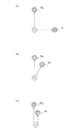
- FIG. 10 is a schematic diagram showing a configuration of a water vapor observation system 1c according to a modification.
- the three receiving portions Rx 1 to Rx 3 are arranged at different height positions.
- the receiving unit Rx 1 is installed at the foot of the mountain MT
- the receiving unit Rx 2 is installed on the middle of the mountain MT
- the receiving unit Rx 3 is installed on the top of the mountain MT.
- the target where each of the receiving portions Rx 1 to Rx 3 is installed may be other than a mountain.
- a steel tower or a building may be used.
- the present invention is not limited thereto.
- an operation panel (not shown) as an operation unit is provided in the water vapor observation system as an example, and the water vapor observation is performed such that a desired reference area is set by the user operating the operation panel.
- a system may be configured. Thereby, since the user can set a desired reference area, an easy-to-use water vapor observation system can be provided.
- FIG. 11 is a block diagram showing a configuration of a water vapor observation system 1d according to a modification.
- FIG. 12 schematically shows the transmission / reception unit TRxa of the water vapor observation system 1d shown in FIG. 11, the transmission wave transmitted by the transmission / reception unit TRxa, and the fixed object S on which the transmission wave is reflected.
- FIG. 12 schematically shows the transmission / reception unit TRxa of the water vapor observation system 1d shown in FIG. 11, the transmission wave transmitted by the transmission / reception unit TRxa, and the fixed object S on which the transmission wave is reflected.
- the position-based relative water vapor amount is calculated as the relative water vapor amount, which is a relative value of water vapor based on the reference water vapor amount to be compared, but is not limited thereto.
- the time-based relative water vapor amount can be calculated as the relative water vapor amount. This time-based relative water vapor amount is the amount of water vapor contained in the areas Z1 to Z8 through which the first transmission wave has passed since the first transmission wave was transmitted and received by the wave receiving unit. Areas Z1 to Z8 through which the second transmission wave passes from when the second transmission wave transmitted later than the first transmission wave is transmitted to when it is received by the receiving unit.
- the time reference relative water vapor amount is a change amount of the water vapor amount in each of the areas Z1 to Z8.
- the time-based relative water vapor amount may be simply referred to as a relative water vapor amount.
- the water vapor observation system 1 d includes one transmission / reception unit TRxa, a calculation processing unit 10 a, and a display unit 9.
- the transmission / reception unit TRxa includes an antenna 7a, a transmission / reception switching unit 8, a signal generator 3, a transmitter 4, and a receiver 6.
- the antenna 7a In the transmission / reception unit TRxa, while the antenna 7a rotates on a horizontal plane, the antenna 7a transmits radio waves to the fixed object S positioned in each direction with respect to the antenna 7a, and the radio waves reflected by the fixed objects S Is received (see FIG. 12).
- the reflected wave (reception wave) from each direction is sequentially received by the antenna 7a, and the reception signals generated from the sequentially received waves are sequentially calculated. Is output to 10a.
- the frequency of the radio wave transmitted and received by the transmission / reception unit is set to 22 GHz.
- the first transmission wave transmitted to each fixed object S is the first transmission wave
- the transmission waves sequentially transmitted with a delay from the first transmission wave are This is the second transmission wave.
- the reflected wave of the first transmission wave is the first received wave
- the reflected wave of the second transmission wave is the second received wave.
- the fixed object S may be a fixed object (tree, land, mountain, etc.) existing in the natural world, or may be an artificial building (building, steel tower, etc.).
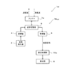
- FIG. 13 is a block diagram showing a configuration of the calculation processing unit 10a.
- FIG. 14 is a graph for explaining the calculation results obtained by the processing performed by the calculation processing unit 10a.
- the calculation processing unit 10a includes a reception level calculation unit 11a, an attenuation amount calculation unit 12a, a relative water vapor amount calculation unit 15 (time reference relative water vapor amount calculation unit), and a distribution image generation unit 14a.
- the reception level calculation unit 11a calculates the echo level of the reception wave coming from each direction based on the reception signals sequentially output from the transmission / reception unit TRxa.
- a value obtained by subtracting the level TL of the first transmission wave by the echo level RL 1 of the first reception wave is calculated as the first attenuation amount A 1 .
- the value obtained by subtracting the level TL of the second transmission wave from the echo levels RL 2 , RL 3 ,... Of the second reception wave is calculated as the second attenuation amounts A 2 , A 3 ,.
- the relative amount of water vapor calculation unit 15, the attenuation A n at time tn to obtain a subtraction value B n by subtracting the attenuation amount A 1 at the reference time t1.
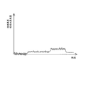
- FIG. 15 is a diagram illustrating an example in which the relative water vapor amount D n in a certain area is graphed.
- the relative water vapor amount in each of the areas Z1 to Z8 that is, the temporal change in the water vapor amount at each subsequent time tn based on the water vapor amount at the reference time t1). Is calculated.
- Distribution image generating unit 14a based on the relative water vapor content D n in each area Z1 ⁇ Z8 calculated by the relative steam quantity calculating section 15, and generates a distribution image of said relative water vapor D n.
- the distribution image generation unit 14a calculates the relative water vapor amount D n in the water vapor observation region Z based on the relative water vapor amount in each of the areas Z1 to Z8 calculated at predetermined timings (that is, at each time t2, t3,). A distribution image is generated at any time.
- the distribution image of the relative water vapor content D n generated by the distribution image generating unit 14a is displayed.
- the distribution image displayed on the display unit 9 is updated as needed to the distribution image generated at the latest time tn.
- the display unit 9 may display a graph shown in FIG. 15 (a graph showing a change in the amount of water vapor in each area).
- the relative water vapor amount D n is calculated based on the radio wave transmitted by the system 1d. Therefore, according to the water vapor observation system 1d, it is possible to provide a water vapor observation system that can observe water vapor regardless of the state of the external system.
- a value obtained by subtracting the echo level of the first received wave from the level of the transmitted wave (first attenuation A 1 ) and the echo level of the second received wave from the level of the transmitted wave are subtracted.
- the relative amount of water vapor D n is calculated. Specifically, the relative water vapor amount D n is calculated by multiplying a value obtained by subtracting each second attenuation amount An by the first attenuation amount A 1 by a predetermined constant. Thus, it is possible to properly calculate the relative water vapor D n.
- the time reference relative water vapor amount at each point is indicated by a color tone as an index representing the water vapor amount.
- a distribution image of the time-based relative water vapor amount is displayed on the display unit 9 of the water vapor observation system 1d.
- the user can grasp
- FIG. 16 is a block diagram showing a configuration of a water vapor observation system 1e according to a modification.
- the configuration of the water vapor observation system for calculating the relative water vapor amount is an example of a water vapor observation system 1d having a wave transmission / reception unit TRxa in which the wave transmission unit and the wave reception unit are integrated. And explained.
- the transmission wave transmitted from the transmission / reception unit TRxa reflects the reflected wave (reception wave) that is reflected by the fixed object S and is received by the transmission / reception unit TRxa.
- the relative water vapor amount D n was calculated.
- the present invention is not limited to this, and as an example, a water vapor observation system 1e having each component shown in FIG. 16 may be configured.
- the transmission wave transmitted from the transmission unit Tx is received as a reception wave by the reception unit Rx arranged at a position different from the transmission unit Tx. Then, the water vapor observation system 1e is based on the received wave received by each of the wave receiving units Rx, as in the case of the calculation processing unit 10a of the water vapor observation system 1d according to the modification shown in FIGS.
- the time reference relative water vapor amount in each of the areas Z1 to Z8 is calculated for each predetermined timing.
- the wave transmitting unit Tx and the plurality of wave receiving units Rx are arranged so that straight lines connecting them to each other form a lattice shape when viewed from above.
- the water vapor amount at the time after that is based on the water vapor amount at the reference time t1.
- a distribution of the amount of change can be obtained.
- the wave transmitting unit Tx and the plurality of wave receiving units Rx 1 to Rx 8 are arranged so that the straight line connecting them to each other forms a lattice shape when viewed from above.
- the areas Z1 to Z8 included in the water vapor observation region Z can be set in a uniform position in the water vapor observation region Z, so that the relative water vapor amount in the water vapor observation region Z can be calculated uniformly.
- the straight line connecting the transmission unit Tx and the plurality of reception units Rx and the transmission unit Tx and the plurality of reception units Rx is in a lattice shape when viewed from above.
- the present invention is not limited to this, and other arrangements may be used.
- the arrangement of the transmission unit Tx and the plurality of reception units Rx 1 and Rx 2 may be as shown in FIGS. 9A to 9C.
- the transmission unit Tx and the plurality of reception units Rx are arranged in a planar shape.
- the present invention is not limited to this, and for example, referring to FIG. May be arranged at different height positions.
- the plurality of wave receiving portions Rx 1 , Rx 2 , Rx 3 are arranged at different height positions.
Landscapes
- Engineering & Computer Science (AREA)
- Radar, Positioning & Navigation (AREA)
- Remote Sensing (AREA)
- Physics & Mathematics (AREA)
- Life Sciences & Earth Sciences (AREA)
- Environmental & Geological Engineering (AREA)
- General Physics & Mathematics (AREA)
- Electromagnetism (AREA)
- Computer Networks & Wireless Communication (AREA)
- Atmospheric Sciences (AREA)
- Environmental Sciences (AREA)
- Ecology (AREA)
- Biodiversity & Conservation Biology (AREA)
- Chemical & Material Sciences (AREA)
- General Health & Medical Sciences (AREA)
- Immunology (AREA)
- Pathology (AREA)
- Biochemistry (AREA)
- Analytical Chemistry (AREA)
- Health & Medical Sciences (AREA)
- Hydrology & Water Resources (AREA)
- Radar Systems Or Details Thereof (AREA)
Abstract
Description
水蒸気観測システム1は、図1に示すように、送波部Txと、複数の受波部Rx(Rx1~Rx8)と、算出処理部10と、表示部9とを備えている。受波部Rx1は第1受波部として設けられ、受波部Rx2~Rx8は第2受波部として設けられている。
以上のように、本実施形態に係る水蒸気観測システム1では、送波部Txから送波された電波が、該送波部Txとは異なる位置に配置された受波部Rxによって受波されるまでの間に、電波の伝搬経路に含まれる水蒸気に起因して減衰する。すなわち、受波部Rxによって受波された電波には、該電波の伝搬経路に含まれる水蒸気に関する情報が含まれている。よって、本実施形態のように受波部Rxによって受波された電波を解析することにより、基準水蒸気量(本実施形態の場合、エリアZ1に含まれる水蒸気量)を基準とした、各エリアZ2~Z8に含まれる水蒸気の相対値である相対水蒸気量C2~C8を算出することができる。
以上、本発明の実施形態について説明したが、本発明はこれらに限定されるものではなく、本発明の趣旨を逸脱しない限りにおいて種々の変更が可能である。
Tx 送波部
TP トランスポンダ(送受波部)
TRx,TRxa 送受波部(送波部、受波部)
Rx,Rx1~Rx8 受波部
13 相対水蒸気量算出部(位置基準相対水蒸気量算出部)
15 相対水蒸気量算出部(時間基準相対水蒸気量算出部)
Claims (21)
- 大気中に含まれる水蒸気を観測する水蒸気観測システムであって、
送信波を送波する送波部と、
前記送波部とは異なる位置に配置され、前記送信波を第1受信波として受波する受波部としての第1受波部と、
前記送波部及び前記第1受波部とは異なる位置に配置され、前記送信波を第2受信波として受波する受波部としての第2受波部と、
前記第1受信波及び前記第2受信波に基づき、前記第1受信波が通過した領域に含まれる水蒸気の量を基準とした、前記第2受信波が通過した領域に含まれる水蒸気の量を、位置基準相対水蒸気量として算出する位置基準相対水蒸気量算出部と、
を備えていることを特徴とする、水蒸気観測システム。 - 請求項1に記載の水蒸気観測システムであって、
互いに異なる位置に配置された複数の前記第2受波部を備えていることを特徴とする、水蒸気観測システム。 - 請求項2に記載の水蒸気観測システムであって、
前記送波部、前記第1受波部、及び複数の前記第2受波部は、これらを互いに繋いだ直線が上方から視て格子状となるように配列されていることを特徴とする、水蒸気観測システム。 - 請求項1から請求項3のいずれか1項に記載の水蒸気観測システムであって、
前記送波部と前記受波部とが一体化された送受波部と備えていることを特徴とする、水蒸気観測システム。 - 請求項4に記載の水蒸気観測システムであって、
前記送受波部として設けられ、前記送波部からの前記送信波を受けて送信波を送波するトランスポンダを備えていることを特徴とする、水蒸気観測システム。 - 請求項1から請求項5のいずれか1項に記載の水蒸気観測システムであって、
前記送波部及び前記受波部の一方は、他方よりも上方に配置されていることを特徴とする、水蒸気観測システム。 - 請求項1から請求項6のいずれか1項に記載の水蒸気観測システムであって、
前記位置基準相対水蒸気量算出部は、前記送信波のレベルから前記第1受信波のエコーレベルを減算した第1減衰量と、前記送信波のレベルから前記第2受信波のエコーレベルを減算した第2減衰量とに基づき、前記位置基準相対水蒸気量を算出することを特徴とする、水蒸気観測システム。 - 大気中に含まれる水蒸気を観測する水蒸気観測システムであって、
第1送信波、及び該第1送信波から遅れて第2送信波を送波する送波部と、
前記第1送信波及び第2送信波のそれぞれが固定物に反射して帰来する反射波のそれぞれを第1受信波及び第2受信波として受波する受波部、又は、前記送波部と異なる位置に配置され、前記第1送信波及び前記第2送信波のそれぞれを、第1受信波及び第2受信波のそれぞれとして受波する受波部と、
前記第1受信波及び前記第2受信波に基づき、前記第1送信波が送波されてから前記受波部に受波されるまでの間に該第1送信波が通過した領域に含まれる水蒸気の量を基準とした、前記第2送信波が送波されてから前記受波部に受波されるまでの間に該第2送信波が通過した領域に含まれる水蒸気の量を、時刻基準相対水蒸気量として算出する時刻基準相対水蒸気量算出部と、
を備えていることを特徴とする、水蒸気観測システム。 - 請求項8に記載の水蒸気観測システムであって、
複数の前記受波部であって、それぞれが、互いに異なる位置に配置されるとともに、前記送波部と異なる位置に配置され、前記第1送信波及び前記第2送信波のそれぞれを前記第1受信波及び前記第2受信波のそれぞれとして受波する複数の前記受波部、を備えていることを特徴とする、水蒸気観測システム。 - 請求項9に記載の水蒸気観測システムであって、
前記送波部及び複数の前記受波部は、これらを互いに繋いだ直線が上方から視て格子状となるように配列されていることを特徴とする、水蒸気観測システム。 - 請求項8から請求項10のいずれか1項に記載の水蒸気観測システムであって、
前記送波部及び前記受波部の一方は、他方よりも上方に配置されていることを特徴とする、水蒸気観測システム。 - 請求項8から請求項11のいずれか1項に記載の水蒸気観測システムであって、
前記時刻基準相対水蒸気量算出部は、前記第1送信波のレベルから前記第1受信波のエコーレベルを減算した第1減衰量と、前記第2送信波のレベルから前記第2受信波のエコーレベルを減算した第2減衰量とに基づき、前記時刻基準相対水蒸気量を算出することを特徴とする、水蒸気観測システム。 - 大気中に含まれる水蒸気を観測する水蒸気観測システムであって、
送信波を送波する送波部と、
前記送信波が固定物に反射して帰来する反射波を受信波として受波する受波部、又は、前記送波部と異なる位置に配置され、前記送信波を受信波として受波する受波部と、
比較対象となる基準水蒸気量を基準とした水蒸気の相対値である相対水蒸気量を、前記受波部で受波された受信波に基づいて算出する相対水蒸気量算出部と、
を備えていることを特徴とする、水蒸気観測システム。 - 請求項13に記載の水蒸気観測システムであって、
前記送波部とは異なる位置に配置され、前記送信波を第1受信波として受波する前記受波部としての第1受波部と、
前記送波部及び前記第1受波部とは異なる位置に配置され、前記送信波を第2受信波として受波する前記受波部としての第2受波部と、
を備え、
前記相対水蒸気量算出部は、前記第1受信波及び前記第2受信波に基づき、前記第1受信波が通過した領域に含まれる水蒸気の量を基準とした、前記第2受信波が通過した領域に含まれる水蒸気の量である位置基準相対水蒸気量を、前記相対水蒸気量として算出する位置基準相対水蒸気量算出部であることを特徴とする、水蒸気観測システム。 - 請求項14に記載の水蒸気観測システムであって、
前記位置基準相対水蒸気量算出部は、前記送信波のレベルから前記第1受信波のエコーレベルを減算した第1減衰量と、前記送信波のレベルから前記第2受信波のエコーレベルを減算した第2減衰量とに基づき、前記位置基準相対水蒸気量を算出することを特徴とする、水蒸気観測システム。 - 請求項13に記載の水蒸気観測システムであって、
前記送波部は、第1送信波、及び該第1送信波よりも遅れて送波される第2送信波を、前記送信波として送波し、
前記受波部は、前記第1送信波及び前記第2送信波のそれぞれが固定物に反射して帰来する反射波のそれぞれを前記受信波としての第1受信波及び第2受信波として受波し、又は、前記送波部と異なる位置に配置され、前記第1送信波及び前記第2送信波のそれぞれを、前記受信波としての第1受信波及び第2受信波のそれぞれとして受波し、
前記相対水蒸気量算出部は、前記第1受信波及び前記第2受信波に基づき、前記第1送信波が送波されてから前記受波部に受波されるまでの間に該第1送信波が通過した領域に含まれる水蒸気の量を基準とした、前記第2送信波が送波されてから前記受波部に受波されるまでの間に該第2送信波が通過した領域に含まれる水蒸気の量である時刻基準相対水蒸気量を、前記相対水蒸気量として算出する時刻基準相対水蒸気量算出部であることを特徴とする、水蒸気観測システム。 - 請求項16に記載の水蒸気観測システムであって、
前記時刻基準相対水蒸気量算出部は、前記第1送信波のレベルから前記第1受信波のエコーレベルを減算した第1減衰量と、前記第2送信波のレベルから前記第2受信波のエコーレベルを減算した第2減衰量とに基づき、前記時刻基準相対水蒸気量を算出することを特徴とする、水蒸気観測システム。 - 請求項1から請求項7、請求項14、及び請求項15のいずれか1項に記載の水蒸気観測システムであって、
前記位置基準相対水蒸気量算出部によって算出された前記位置基準相対水蒸気量の指標を表示する表示部、を更に備えていることを特徴とする、水蒸気観測システム。 - 請求項18に記載の水蒸気観測システムであって、
前記表示部は、前記位置基準相対水蒸気量算出部によって算出された前記位置基準相対水蒸気量の分布を前記指標として表示することを特徴とする、水蒸気観測システム。 - 請求項8から請求項12、請求項16、及び請求項17のいずれか1項に記載の水蒸気観測システムであって、
前記時刻基準相対水蒸気量算出部によって算出された前記時刻基準相対水蒸気量の指標を表示する表示部、を更に備えていることを特徴とする、水蒸気観測システム。 - 請求項20に記載の水蒸気観測システムであって、
前記表示部は、前記時刻基準相対水蒸気量算出部によって算出された前記時刻基準相対水蒸気量の分布を前記指標として表示することを特徴とする、水蒸気観測システム。
Priority Applications (3)
| Application Number | Priority Date | Filing Date | Title |
|---|---|---|---|
| US15/748,052 US10690603B2 (en) | 2015-07-28 | 2016-06-08 | Water vapor observing system |
| EP16830166.1A EP3330746B1 (en) | 2015-07-28 | 2016-06-08 | Water vapor observation system |
| JP2017531063A JP6592092B2 (ja) | 2015-07-28 | 2016-06-08 | 水蒸気観測システム |
Applications Claiming Priority (2)
| Application Number | Priority Date | Filing Date | Title |
|---|---|---|---|
| JP2015148467 | 2015-07-28 | ||
| JP2015-148467 | 2015-07-28 |
Publications (1)
| Publication Number | Publication Date |
|---|---|
| WO2017018061A1 true WO2017018061A1 (ja) | 2017-02-02 |
Family
ID=57885675
Family Applications (1)
| Application Number | Title | Priority Date | Filing Date |
|---|---|---|---|
| PCT/JP2016/066984 Ceased WO2017018061A1 (ja) | 2015-07-28 | 2016-06-08 | 水蒸気観測システム |
Country Status (4)
| Country | Link |
|---|---|
| US (1) | US10690603B2 (ja) |
| EP (1) | EP3330746B1 (ja) |
| JP (1) | JP6592092B2 (ja) |
| WO (1) | WO2017018061A1 (ja) |
Cited By (5)
| Publication number | Priority date | Publication date | Assignee | Title |
|---|---|---|---|---|
| WO2020230502A1 (ja) * | 2019-05-14 | 2020-11-19 | 古野電気株式会社 | 観測信号生成装置、観測装置、観測信号生成方法、観測方法、観測信号生成プログラム、および、観測プログラム |
| US20220326164A1 (en) * | 2020-02-14 | 2022-10-13 | Furuno Electric Co., Ltd. | Water vapor observation device, water vapor observation system, water vapor observation method, and recording medium |
| JP2023044368A (ja) * | 2021-09-17 | 2023-03-30 | 日本アンテナ株式会社 | 水蒸気量の観測装置 |
| JP2023044369A (ja) * | 2021-09-17 | 2023-03-30 | 日本アンテナ株式会社 | 水蒸気量観測システム |
| WO2025004425A1 (ja) * | 2023-06-28 | 2025-01-02 | 国立研究開発法人防災科学技術研究所 | 気象レーダ装置 |
Families Citing this family (1)
| Publication number | Priority date | Publication date | Assignee | Title |
|---|---|---|---|---|
| EP4184222B1 (en) * | 2020-07-14 | 2025-03-26 | Furuno Electric Co., Ltd. | Precipitable water estimation model learning system, precipitable water estimation system, method, and program |
Citations (4)
| Publication number | Priority date | Publication date | Assignee | Title |
|---|---|---|---|---|
| JPH02280083A (ja) * | 1989-04-20 | 1990-11-16 | Nec Corp | 水蒸気量・雨量測定装置 |
| JPH05223951A (ja) * | 1992-02-18 | 1993-09-03 | Oki Electric Ind Co Ltd | 区間降雨検出システム |
| JP2001231716A (ja) * | 2000-02-22 | 2001-08-28 | Toto Ltd | 可動体検知装置、及びトイレ装置 |
| US20090160700A1 (en) * | 2005-07-13 | 2009-06-25 | Hagit Messer-Yaron | Monitoring and Mapping of Atmospheric Phenomena |
Family Cites Families (3)
| Publication number | Priority date | Publication date | Assignee | Title |
|---|---|---|---|---|
| US4876647A (en) * | 1985-05-17 | 1989-10-24 | The Standard Oil Company | Apparatus for determining water stress in crops |
| JP2004093291A (ja) * | 2002-08-30 | 2004-03-25 | Japan Science & Technology Corp | 雨量測定装置、雨量測定方法及び雨量測定システム |
| ITGE20120071A1 (it) * | 2012-07-19 | 2014-01-20 | Darts Engineering Srl | Sistema e metodo di monitoraggio di un territorio |
-
2016
- 2016-06-08 JP JP2017531063A patent/JP6592092B2/ja active Active
- 2016-06-08 US US15/748,052 patent/US10690603B2/en active Active
- 2016-06-08 EP EP16830166.1A patent/EP3330746B1/en active Active
- 2016-06-08 WO PCT/JP2016/066984 patent/WO2017018061A1/ja not_active Ceased
Patent Citations (4)
| Publication number | Priority date | Publication date | Assignee | Title |
|---|---|---|---|---|
| JPH02280083A (ja) * | 1989-04-20 | 1990-11-16 | Nec Corp | 水蒸気量・雨量測定装置 |
| JPH05223951A (ja) * | 1992-02-18 | 1993-09-03 | Oki Electric Ind Co Ltd | 区間降雨検出システム |
| JP2001231716A (ja) * | 2000-02-22 | 2001-08-28 | Toto Ltd | 可動体検知装置、及びトイレ装置 |
| US20090160700A1 (en) * | 2005-07-13 | 2009-06-25 | Hagit Messer-Yaron | Monitoring and Mapping of Atmospheric Phenomena |
Non-Patent Citations (1)
| Title |
|---|
| MASANORI NISHIO ET AL.: "Development of Nano- Satellites for Regional Disaster Prevention - Industry-University-Government Collaborated Activities in Kagoshima", PROCEEDINGS OF SPACE SCIENCES AND TECHNOLOGY CONFERENCE, vol. 50, 9 November 2006 (2006-11-09), pages 2A04, XP009508711 * |
Cited By (11)
| Publication number | Priority date | Publication date | Assignee | Title |
|---|---|---|---|---|
| WO2020230502A1 (ja) * | 2019-05-14 | 2020-11-19 | 古野電気株式会社 | 観測信号生成装置、観測装置、観測信号生成方法、観測方法、観測信号生成プログラム、および、観測プログラム |
| JPWO2020230502A1 (ja) * | 2019-05-14 | 2020-11-19 | ||
| JP7488814B2 (ja) | 2019-05-14 | 2024-05-22 | 古野電気株式会社 | 観測信号生成装置、観測装置、観測信号生成方法、観測方法、観測信号生成プログラム、および、観測プログラム |
| US12188881B2 (en) | 2019-05-14 | 2025-01-07 | Furuno Electric Co., Ltd. | Observation signal generation device, observation device, observation signal generation method, and observation method |
| US20220326164A1 (en) * | 2020-02-14 | 2022-10-13 | Furuno Electric Co., Ltd. | Water vapor observation device, water vapor observation system, water vapor observation method, and recording medium |
| US11703462B2 (en) * | 2020-02-14 | 2023-07-18 | Furuno Electric Co., Ltd. | Water vapor observation device, water vapor observation system, water vapor observation method, and recording medium |
| JP2023044368A (ja) * | 2021-09-17 | 2023-03-30 | 日本アンテナ株式会社 | 水蒸気量の観測装置 |
| JP2023044369A (ja) * | 2021-09-17 | 2023-03-30 | 日本アンテナ株式会社 | 水蒸気量観測システム |
| JP7739103B2 (ja) | 2021-09-17 | 2025-09-16 | 日本アンテナ株式会社 | 水蒸気量観測システム |
| JP7755423B2 (ja) | 2021-09-17 | 2025-10-16 | 日本アンテナ株式会社 | 水蒸気量の観測装置 |
| WO2025004425A1 (ja) * | 2023-06-28 | 2025-01-02 | 国立研究開発法人防災科学技術研究所 | 気象レーダ装置 |
Also Published As
| Publication number | Publication date |
|---|---|
| JPWO2017018061A1 (ja) | 2018-05-24 |
| JP6592092B2 (ja) | 2019-10-16 |
| EP3330746A1 (en) | 2018-06-06 |
| US10690603B2 (en) | 2020-06-23 |
| EP3330746A4 (en) | 2019-03-27 |
| EP3330746B1 (en) | 2020-10-14 |
| US20180209919A1 (en) | 2018-07-26 |
Similar Documents
| Publication | Publication Date | Title |
|---|---|---|
| JP6592092B2 (ja) | 水蒸気観測システム | |
| CN104849712B (zh) | 一种基于多基地mimo‑sar的三维形变监测系统 | |
| JP6099318B2 (ja) | 水蒸気観測装置および気象レーダ | |
| CN105229487B (zh) | 用于定位目标的方法和实施此方法的多基地雷达系统 | |
| JP2021509171A (ja) | 第2のデバイスの既知のロケーションに基づいて第1のデバイスのロケーションを求めるミリ波通信システム及び方法 | |
| JP5197138B2 (ja) | マルチスタティックレーダ装置 | |
| US7782247B1 (en) | System and method for target location | |
| JP2011257150A (ja) | 方位検出装置 | |
| JP5238531B2 (ja) | レーダ装置、海洋レーダ観測装置およびドップラ周波数データ算出方法 | |
| JP2011242182A (ja) | パッシブレーダシステムおよびパッシブレーダ方法 | |
| JP2025508629A (ja) | ドップラーレーダ共存 | |
| JP2015166732A (ja) | 強化された撮像システム | |
| WO2019176747A1 (ja) | 電波環境表示装置および電波環境表示方法 | |
| KR101252485B1 (ko) | 바이스태틱 레이더의 고속 영상 형성 방법 및 고속 영상 형성 장치 | |
| KR101303766B1 (ko) | Fmcw 근접센서의 성능평가를 위한 시뮬레이터 및 방법 | |
| WO2017018062A1 (ja) | 水蒸気観測装置 | |
| JP4266810B2 (ja) | 風速ベクトル算出装置 | |
| WO2016076052A1 (ja) | 超音波診断装置 | |
| De la Vega et al. | Software tool for the analysis of potential impact of wind farms on radiocommunication services | |
| JP5379312B2 (ja) | 距離測定装置 | |
| JP2019152606A (ja) | 気象レーダ偽像判定装置、プログラム及び方法 | |
| JP2011153959A (ja) | レーダ信号処理装置 | |
| JP3292679B2 (ja) | レーダ装置 | |
| CN106342214B (zh) | 一种电离层侧向散射探测方法 | |
| JP7739103B2 (ja) | 水蒸気量観測システム |
Legal Events
| Date | Code | Title | Description |
|---|---|---|---|
| 121 | Ep: the epo has been informed by wipo that ep was designated in this application |
Ref document number: 16830166 Country of ref document: EP Kind code of ref document: A1 |
|
| ENP | Entry into the national phase |
Ref document number: 2017531063 Country of ref document: JP Kind code of ref document: A |
|
| WWE | Wipo information: entry into national phase |
Ref document number: 15748052 Country of ref document: US |
|
| NENP | Non-entry into the national phase |
Ref country code: DE |
|
| WWE | Wipo information: entry into national phase |
Ref document number: 2016830166 Country of ref document: EP |