WO2017018118A1 - 眼内装着物及び眼内装着物の保持部材 - Google Patents
眼内装着物及び眼内装着物の保持部材 Download PDFInfo
- Publication number
- WO2017018118A1 WO2017018118A1 PCT/JP2016/069228 JP2016069228W WO2017018118A1 WO 2017018118 A1 WO2017018118 A1 WO 2017018118A1 JP 2016069228 W JP2016069228 W JP 2016069228W WO 2017018118 A1 WO2017018118 A1 WO 2017018118A1
- Authority
- WO
- WIPO (PCT)
- Prior art keywords
- ciliary
- lens
- eye
- collar
- intraocular
- Prior art date
- Legal status (The legal status is an assumption and is not a legal conclusion. Google has not performed a legal analysis and makes no representation as to the accuracy of the status listed.)
- Ceased
Links
- 0 *C1C(CCCN)C1 Chemical compound *C1C(CCCN)C1 0.000 description 1
Images










Classifications
-
- A—HUMAN NECESSITIES
- A61—MEDICAL OR VETERINARY SCIENCE; HYGIENE
- A61F—FILTERS IMPLANTABLE INTO BLOOD VESSELS; PROSTHESES; DEVICES PROVIDING PATENCY TO, OR PREVENTING COLLAPSING OF, TUBULAR STRUCTURES OF THE BODY, e.g. STENTS; ORTHOPAEDIC, NURSING OR CONTRACEPTIVE DEVICES; FOMENTATION; TREATMENT OR PROTECTION OF EYES OR EARS; BANDAGES, DRESSINGS OR ABSORBENT PADS; FIRST-AID KITS
- A61F2/00—Filters implantable into blood vessels; Prostheses, i.e. artificial substitutes or replacements for parts of the body; Appliances for connecting them with the body; Devices providing patency to, or preventing collapsing of, tubular structures of the body, e.g. stents
- A61F2/02—Prostheses implantable into the body
- A61F2/14—Eye parts, e.g. lenses or corneal implants; Artificial eyes
- A61F2/16—Intraocular lenses
-
- A—HUMAN NECESSITIES
- A61—MEDICAL OR VETERINARY SCIENCE; HYGIENE
- A61F—FILTERS IMPLANTABLE INTO BLOOD VESSELS; PROSTHESES; DEVICES PROVIDING PATENCY TO, OR PREVENTING COLLAPSING OF, TUBULAR STRUCTURES OF THE BODY, e.g. STENTS; ORTHOPAEDIC, NURSING OR CONTRACEPTIVE DEVICES; FOMENTATION; TREATMENT OR PROTECTION OF EYES OR EARS; BANDAGES, DRESSINGS OR ABSORBENT PADS; FIRST-AID KITS
- A61F2/00—Filters implantable into blood vessels; Prostheses, i.e. artificial substitutes or replacements for parts of the body; Appliances for connecting them with the body; Devices providing patency to, or preventing collapsing of, tubular structures of the body, e.g. stents
- A61F2/02—Prostheses implantable into the body
- A61F2/14—Eye parts, e.g. lenses or corneal implants; Artificial eyes
- A61F2/16—Intraocular lenses
- A61F2/1602—Corrective lenses for use in addition to the natural lenses of the eyes or for pseudo-phakic eyes
- A61F2/1605—Anterior chamber lenses for use in addition to the natural lenses of the eyes, e.g. iris fixated, iris floating
- A61F2/1608—Iris fixated, e.g. by clamping iris tissue, by suturing to the iris
-
- A—HUMAN NECESSITIES
- A61—MEDICAL OR VETERINARY SCIENCE; HYGIENE
- A61F—FILTERS IMPLANTABLE INTO BLOOD VESSELS; PROSTHESES; DEVICES PROVIDING PATENCY TO, OR PREVENTING COLLAPSING OF, TUBULAR STRUCTURES OF THE BODY, e.g. STENTS; ORTHOPAEDIC, NURSING OR CONTRACEPTIVE DEVICES; FOMENTATION; TREATMENT OR PROTECTION OF EYES OR EARS; BANDAGES, DRESSINGS OR ABSORBENT PADS; FIRST-AID KITS
- A61F2/00—Filters implantable into blood vessels; Prostheses, i.e. artificial substitutes or replacements for parts of the body; Appliances for connecting them with the body; Devices providing patency to, or preventing collapsing of, tubular structures of the body, e.g. stents
- A61F2/02—Prostheses implantable into the body
- A61F2/14—Eye parts, e.g. lenses or corneal implants; Artificial eyes
- A61F2/16—Intraocular lenses
- A61F2/1613—Intraocular lenses having special lens configurations, e.g. multipart lenses; having particular optical properties, e.g. pseudo-accommodative lenses, lenses having aberration corrections, diffractive lenses, lenses for variably absorbing electromagnetic radiation, lenses having variable focus
- A61F2/1624—Intraocular lenses having special lens configurations, e.g. multipart lenses; having particular optical properties, e.g. pseudo-accommodative lenses, lenses having aberration corrections, diffractive lenses, lenses for variably absorbing electromagnetic radiation, lenses having variable focus having adjustable focus; power activated variable focus means, e.g. mechanically or electrically by the ciliary muscle or from the outside
- A61F2/1629—Intraocular lenses having special lens configurations, e.g. multipart lenses; having particular optical properties, e.g. pseudo-accommodative lenses, lenses having aberration corrections, diffractive lenses, lenses for variably absorbing electromagnetic radiation, lenses having variable focus having adjustable focus; power activated variable focus means, e.g. mechanically or electrically by the ciliary muscle or from the outside for changing longitudinal position, i.e. along the visual axis when implanted
-
- A—HUMAN NECESSITIES
- A61—MEDICAL OR VETERINARY SCIENCE; HYGIENE
- A61F—FILTERS IMPLANTABLE INTO BLOOD VESSELS; PROSTHESES; DEVICES PROVIDING PATENCY TO, OR PREVENTING COLLAPSING OF, TUBULAR STRUCTURES OF THE BODY, e.g. STENTS; ORTHOPAEDIC, NURSING OR CONTRACEPTIVE DEVICES; FOMENTATION; TREATMENT OR PROTECTION OF EYES OR EARS; BANDAGES, DRESSINGS OR ABSORBENT PADS; FIRST-AID KITS
- A61F2/00—Filters implantable into blood vessels; Prostheses, i.e. artificial substitutes or replacements for parts of the body; Appliances for connecting them with the body; Devices providing patency to, or preventing collapsing of, tubular structures of the body, e.g. stents
- A61F2/02—Prostheses implantable into the body
- A61F2/14—Eye parts, e.g. lenses or corneal implants; Artificial eyes
- A61F2/16—Intraocular lenses
- A61F2/1662—Instruments for inserting intraocular lenses into the eye
- A61F2/1664—Instruments for inserting intraocular lenses into the eye for manual insertion during surgery, e.g. forceps-like instruments
-
- A—HUMAN NECESSITIES
- A61—MEDICAL OR VETERINARY SCIENCE; HYGIENE
- A61F—FILTERS IMPLANTABLE INTO BLOOD VESSELS; PROSTHESES; DEVICES PROVIDING PATENCY TO, OR PREVENTING COLLAPSING OF, TUBULAR STRUCTURES OF THE BODY, e.g. STENTS; ORTHOPAEDIC, NURSING OR CONTRACEPTIVE DEVICES; FOMENTATION; TREATMENT OR PROTECTION OF EYES OR EARS; BANDAGES, DRESSINGS OR ABSORBENT PADS; FIRST-AID KITS
- A61F2/00—Filters implantable into blood vessels; Prostheses, i.e. artificial substitutes or replacements for parts of the body; Appliances for connecting them with the body; Devices providing patency to, or preventing collapsing of, tubular structures of the body, e.g. stents
- A61F2/02—Prostheses implantable into the body
- A61F2/14—Eye parts, e.g. lenses or corneal implants; Artificial eyes
- A61F2/16—Intraocular lenses
- A61F2002/1681—Intraocular lenses having supporting structure for lens, e.g. haptics
-
- A—HUMAN NECESSITIES
- A61—MEDICAL OR VETERINARY SCIENCE; HYGIENE
- A61F—FILTERS IMPLANTABLE INTO BLOOD VESSELS; PROSTHESES; DEVICES PROVIDING PATENCY TO, OR PREVENTING COLLAPSING OF, TUBULAR STRUCTURES OF THE BODY, e.g. STENTS; ORTHOPAEDIC, NURSING OR CONTRACEPTIVE DEVICES; FOMENTATION; TREATMENT OR PROTECTION OF EYES OR EARS; BANDAGES, DRESSINGS OR ABSORBENT PADS; FIRST-AID KITS
- A61F2/00—Filters implantable into blood vessels; Prostheses, i.e. artificial substitutes or replacements for parts of the body; Appliances for connecting them with the body; Devices providing patency to, or preventing collapsing of, tubular structures of the body, e.g. stents
- A61F2/02—Prostheses implantable into the body
- A61F2/14—Eye parts, e.g. lenses or corneal implants; Artificial eyes
- A61F2/16—Intraocular lenses
- A61F2002/1681—Intraocular lenses having supporting structure for lens, e.g. haptics
- A61F2002/1682—Intraocular lenses having supporting structure for lens, e.g. haptics having mechanical force transfer mechanism to the lens, e.g. for accommodating lenses
-
- A—HUMAN NECESSITIES
- A61—MEDICAL OR VETERINARY SCIENCE; HYGIENE
- A61F—FILTERS IMPLANTABLE INTO BLOOD VESSELS; PROSTHESES; DEVICES PROVIDING PATENCY TO, OR PREVENTING COLLAPSING OF, TUBULAR STRUCTURES OF THE BODY, e.g. STENTS; ORTHOPAEDIC, NURSING OR CONTRACEPTIVE DEVICES; FOMENTATION; TREATMENT OR PROTECTION OF EYES OR EARS; BANDAGES, DRESSINGS OR ABSORBENT PADS; FIRST-AID KITS
- A61F2/00—Filters implantable into blood vessels; Prostheses, i.e. artificial substitutes or replacements for parts of the body; Appliances for connecting them with the body; Devices providing patency to, or preventing collapsing of, tubular structures of the body, e.g. stents
- A61F2/02—Prostheses implantable into the body
- A61F2/14—Eye parts, e.g. lenses or corneal implants; Artificial eyes
- A61F2/16—Intraocular lenses
- A61F2002/1681—Intraocular lenses having supporting structure for lens, e.g. haptics
- A61F2002/16903—Having means to temporarily stabilize haptic
-
- A—HUMAN NECESSITIES
- A61—MEDICAL OR VETERINARY SCIENCE; HYGIENE
- A61F—FILTERS IMPLANTABLE INTO BLOOD VESSELS; PROSTHESES; DEVICES PROVIDING PATENCY TO, OR PREVENTING COLLAPSING OF, TUBULAR STRUCTURES OF THE BODY, e.g. STENTS; ORTHOPAEDIC, NURSING OR CONTRACEPTIVE DEVICES; FOMENTATION; TREATMENT OR PROTECTION OF EYES OR EARS; BANDAGES, DRESSINGS OR ABSORBENT PADS; FIRST-AID KITS
- A61F2/00—Filters implantable into blood vessels; Prostheses, i.e. artificial substitutes or replacements for parts of the body; Appliances for connecting them with the body; Devices providing patency to, or preventing collapsing of, tubular structures of the body, e.g. stents
- A61F2/02—Prostheses implantable into the body
- A61F2/14—Eye parts, e.g. lenses or corneal implants; Artificial eyes
- A61F2/16—Intraocular lenses
- A61F2002/16965—Lens includes ultraviolet absorber
- A61F2002/1699—Additional features not otherwise provided for
-
- A—HUMAN NECESSITIES
- A61—MEDICAL OR VETERINARY SCIENCE; HYGIENE
- A61F—FILTERS IMPLANTABLE INTO BLOOD VESSELS; PROSTHESES; DEVICES PROVIDING PATENCY TO, OR PREVENTING COLLAPSING OF, TUBULAR STRUCTURES OF THE BODY, e.g. STENTS; ORTHOPAEDIC, NURSING OR CONTRACEPTIVE DEVICES; FOMENTATION; TREATMENT OR PROTECTION OF EYES OR EARS; BANDAGES, DRESSINGS OR ABSORBENT PADS; FIRST-AID KITS
- A61F2220/00—Fixations or connections for prostheses classified in groups A61F2/00 - A61F2/26 or A61F2/82 or A61F9/00 or A61F11/00 or subgroups thereof
- A61F2220/0008—Fixation appliances for connecting prostheses to the body
- A61F2220/0016—Fixation appliances for connecting prostheses to the body with sharp anchoring protrusions, e.g. barbs, pins, spikes
-
- A—HUMAN NECESSITIES
- A61—MEDICAL OR VETERINARY SCIENCE; HYGIENE
- A61F—FILTERS IMPLANTABLE INTO BLOOD VESSELS; PROSTHESES; DEVICES PROVIDING PATENCY TO, OR PREVENTING COLLAPSING OF, TUBULAR STRUCTURES OF THE BODY, e.g. STENTS; ORTHOPAEDIC, NURSING OR CONTRACEPTIVE DEVICES; FOMENTATION; TREATMENT OR PROTECTION OF EYES OR EARS; BANDAGES, DRESSINGS OR ABSORBENT PADS; FIRST-AID KITS
- A61F2230/00—Geometry of prostheses classified in groups A61F2/00 - A61F2/26 or A61F2/82 or A61F9/00 or A61F11/00 or subgroups thereof
- A61F2230/0002—Two-dimensional shapes, e.g. cross-sections
- A61F2230/0004—Rounded shapes, e.g. with rounded corners
- A61F2230/0013—Horseshoe-shaped, e.g. crescent-shaped, C-shaped, U-shaped
Definitions
- the present invention relates to an intraocular attachment and a holding member for the intraocular attachment.
- the lens is held in the eye with the legs extending from the lens fixed to the outside of the sclera. Accordingly, the relaxation / contraction movement of the ciliary muscle is hardly transmitted from the leg portion to the lens, and the lens is indirectly linked through the sac (anterior capsule / rear capsule) that moves by the relaxation / contraction of the ciliary muscle.
- the intraocular attachment of the present invention is The root of the ciliary protrusion protruding from the ciliary body located in the circumferential direction with respect to the visual axis to the visual axis from the root of the ciliary protrusion along the outer surface of the ciliary protrusion through the tip of the ciliary protrusion A buttock extending to Legs extending from the buttocks toward the visual axis; An object to be attached to the eye supported by the leg, and The mounted object is held in the eye in a state where the buttocks are caught or fitted on the ciliary protrusion.
- the holding member of the intraocular attachment of the present invention is A holding member for an intraocular wearing object that is connected to a leg portion that supports the wearing object to be worn in the eye and holds the wearing object in the eye,
- the root of the ciliary protrusion protruding from the ciliary body located in the circumferential direction with respect to the visual axis to the visual axis from the root of the ciliary protrusion along the outer surface of the ciliary protrusion through the tip of the ciliary protrusion
- With a buttock extending to The mounted object is held in the eye in a state where the buttocks are caught or fitted on the ciliary protrusion.
- the present invention is configured as a holding member for an intraocular attachment (the above-described invention is configured as an intraocular attachment). Similar to the aforementioned invention of the intraocular attachment, the ciliary muscle relaxation / contraction motion is directly transmitted from the buttocks to the attachment through the leg, and the attachment attached to the eye is referred to as the ciliary muscle.
- the object to be mounted can be held so as to be directly linked to the relaxation / contraction of the body.
- the above-mentioned intraocular attachment and the buttocks in the holding member for the intraocular attachment are: A plurality of unit ridges formed adjacent to each other around the visual axis, extending from the root portion along the ciliary projection to the root portion on the opposite side from the root portion; A connecting portion for connecting a plurality of adjacent unit collars; Is provided.
- a plurality of unit collars adjacent to each other around the visual axis are connected, and the number of places where the collar part is caught or fitted to the ciliary protrusion by the plurality of unit collars. Therefore, it becomes easy to catch or fit a collar part on a ciliary projection. In addition, when the buttocks are caught or fitted on the ciliary protrusion, it is possible to stably hold the object to be worn in the eye.
- the connecting portion connects a plurality of adjacent unit collars in a comb shape or a net shape. Therefore, the strength of the buttocks can be increased.
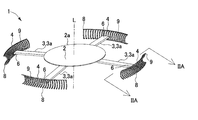
- FIG. 1B is a schematic front view of the intraocular lens of FIG. 1A.
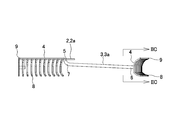
- FIG. 1B is a schematic plan view of the intraocular lens of FIG. 1A. IIA-IIA enlarged view of FIG. 1A. IIB-IIB enlarged view of FIG. 1B.
- FIG. 2B is an enlarged view of IIC-IIC in FIG. 2B.
- the model front view which shows one unit collar part in FIG. 2C.
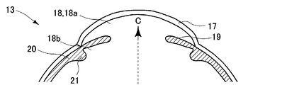
- the schematic cross section which shows typically the inside of the patient's eye before a crystalline lens is extracted.
- 3C is a schematic cross-sectional view showing a state where the entire lens has been extracted from the eye of FIG. 3A.
- FIG. FIG. 3B is a schematic cross-sectional view showing a state where an insertion instrument is inserted into the eye of FIG. 3B.
- FIG. 3C is a schematic cross-sectional view showing a state where the intraocular lens of FIG. 1A is attached in the eye of the patient following FIG. 3C.
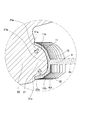
- the elements on larger scale of FIG. 3D The model perspective view which shows the modification 1 of FIG. 1A.
- the model perspective view which shows the modification 2 of FIG. 1A.
- the model perspective view which shows the modification 3 of FIG. 1A.
- FIG. 5B is an enlarged view of VC-VC in FIG. 5A.
- FIG. 6B is a schematic front view of the intraocular lens of FIG. 6A.
- FIG. 6B is a schematic plan view of the intraocular lens of FIG. 6A.
- FIG. 6B is a schematic side view of the intraocular lens of FIG. 6A.
- the schematic cross section which shows typically the inside of the patient's eye from which the lens was extracted leaving a part of anterior capsule and a back capsule.
- FIG. 7B is a schematic cross-sectional view showing a state where an insertion instrument is inserted into the eye of FIG. 7A.
- FIG. 7B is a schematic cross-sectional view showing a state where the intraocular lens of FIG.
- FIG. 6A is attached in the eye of the patient following FIG. 7B. The elements on larger scale of FIG. 7C.
- the lens 2 is elastic and formed in a disk shape, and performs a lens function instead of a lens (for example, a clouded lens) removed from a cataract patient.
- 1A indicates a vertical axis L passing through the center of the surface of the lens 2 and is shown for convenience.
- the lens 2 is supported by the leg 3.
- the leg portion 3 has a plurality of (four in the first embodiment) legs 3 a that support the lens 2.
- Each leg 3a extends from a plurality of positions in the circumferential direction of the lens 2 (a plurality of positions on the outer peripheral portion 2a on the back surface of the lens 2) to the side of the lens 2 (a direction away from the axis L).
- the leg 3 a is at one end 5 located on the side close to the lens 2, the other end 6 located on the side far from the lens 2, and a position between the one end 5 and the other end 6. It has the bending part 7 which changes the direction where the leg 3a extends.
- the one end portion 5 is located on the outer peripheral portion 2a (a part of the outer peripheral portion 2a) on the back surface of the lens 2, and is a base point of the leg 3a extending from the lens 2.
- the other end portion 6 is an end portion of a leg 3 a extending from the one end portion 5 to the side of the lens 2.
- the bending portion 7 is located on the one end portion 5 side, and is bent toward the outside of the lens 2 by curving a leg 3a extending obliquely downward from the rear surface of the lens 2 so as to be away from the axis L.
- each leg 3a is provided with a collar portion 4.
- a plurality of flanges 4 are discontinuously arranged around the axis L (four are arranged at equal intervals around the axis L).
- the collar part 4 includes a plurality of unit collar parts 8 (refer to FIGS. 2A and 2B) formed in a substantially C-shaped nail shape so as to protrude convexly toward the center part (axis L) of the lens 2, A connecting portion 9 that connects the plurality of unit collar portions 8 is provided.
- the substantially C-shaped unit collar 8 has a length (straight line D1) connecting the end 11a of the upper part 11 and the end 12a of the lower part 12 at the shortest distance within a range of 1 mm to 4 mm. It is desirable. It is desirable that the maximum length of the perpendicular line (straight line D2) extending from the intermediate portion 10 to the straight line D1 is in the range of 0.5 mm to 2 mm. Further, the ratio of the straight line D1 and the straight line D2 is preferably between 2: 1 and 8: 1.
- the plurality of unit flanges 8 are arranged adjacent to each other at equal intervals over the range of the acute angle ⁇ around the axis L.
- the adjacent unit flanges 8 are preferably arranged around the axis L every angle ⁇ (for example, 1 to 9 degrees).
- a plurality of unit collars 8 arranged adjacent to each other are connected by a connecting part 9.
- the connecting portion 9 is positioned so as to connect the end portions 11a (see FIG. 2C) of the plurality of adjacent unit collar portions 8 over the range of the acute angle ⁇ around the axis L. Therefore, as shown in FIG. 2A, the collar portion 4 is formed in a comb shape as a whole.
- the collar part 4 (unit collar part 8 and connecting part 9) is a material having elasticity, and is made of, for example, an elastomer resin.
- the collar part 4 and the leg part 3 may be integrally formed, or after the collar part 4 and the leg part 3 are formed separately, the collar part 4 and the leg part are formed by a well-known method (for example, adhesion using a contact material). 3 may be joined.
- the intraocular lens 1 having the above configuration is mounted in the eye instead of the crystalline lens of a cataract patient.
- a series of flows in which the doctor mounts the intraocular lens 1 in the patient's eye will be described.
- an example in which the intraocular lens 1 is mounted in the eye of a patient who has extracted all of the crystalline lens (and also removed the sac) will be described.
- FIG. 3A schematically shows a patient's eye 13 and shows a state before the lens 14 of a cataract patient is removed.
- the lens 14 of the patient with cataract is removed together with the anterior capsule 15 and the posterior capsule 16.
- the iris 19 located in the eye chamber 18 (between the anterior chamber 18a and the posterior chamber 18b) behind the cornea 17 (the lower side in the drawing) is opened by the medicine.
- a ciliary body 20 (ciliary muscle) is positioned in the circumferential direction with respect to the visual axis C of the patient (the ciliary body 20 is positioned in an annular shape), and the ciliary projection from the ciliary body 20 toward the visual axis C. 21 protrudes, and the ciliary protrusion 21 is connected to the crystalline lens 14 by a chin band 22.
- the doctor removes all of the patient's crystalline lens 14 (FIG. 3A) and chin band 22 by a well-known method (FIG. 3B). Thereafter, as shown in FIG. 3C, the doctor incises a part of the cornea 17 to form an insertion hole 23 for inserting the distal end portion of the insertion instrument I for inserting the intraocular lens 1 into the eye. . The doctor also forms an insertion hole 24 for inserting a lever (not shown) for operating the intraocular lens 1 inserted into the eye into the eye.
- the intraocular lens 1 that can be elastically deformed is stored in a cylindrical shape.
- the doctor inserts the distal end of the insertion instrument I in which the intraocular lens 1 is accommodated from the insertion hole 23, causes the distal end to reach the posterior chamber 18 b, and discharges the intraocular lens 1 from the distal end of the insertion instrument I into the posterior chamber 18 b. To do.
- the doctor inserts an insulator (not shown) into the eye from the insertion hole 24, picks the leg 3a (see FIG. 1A) of the intraocular lens 1 discharged into the eye, and is provided at the other end 6 of the leg 3a.
- the collar 4 is pulled toward the ciliary protrusion 21.
- the doctor places the heel part 4 (a plurality of adjacent unit heel parts 8) so as to push the ciliary protrusion 21 into the space between the upper part 11 and the lower part 12 of the substantially C-shaped unit heel part 8 (see FIG. 2C). Is pressed against the ciliary protrusion 21.
- the unit collar portion 8 is elastically deformed so that the space between the upper portion 11 and the lower portion 12 is expanded.
- the doctor confirms that the ciliary protrusion 21 has been pushed between the upper part 11 and the lower part 12, and then removes the leg 3a picked with the insulator from the insulator.
- each unit collar 8 may be fitted into the ciliary protrusion 21 with a lever.
- the doctor When the buttocks 4 are fitted into the ciliary protrusions 21, the doctor performs the same operation on the buttocks 4 provided on the remaining three legs 3 a, so that the intraocular lens 1 is intraocularly moved by the buttocks 4.
- the lens 2 Retained. 3D, the lens 2 is positioned in the posterior chamber 18b with the intraocular lens 1 held in the eye by the buttocks 4, and the axis L of the lens 2 is aligned with the visual axis C of the patient's eye. Located so as to overlap. Then, a doctor takes out the insulator etc. outside the eyeball, and the mounting
- the collar 4 extends from the root 21 a of the ciliary protrusion 21 to the outer surface of the ciliary protrusion 21.
- the distal end portion 21b of the ciliary protrusion 21 extends to the opposite root portion 21c.
- the ciliary protrusion 21 moves toward the visual axis C, for example, obliquely upward as shown by the arrow in FIG.
- the collar portion 4 attached to the ciliary protrusion 21 is interlocked.
- the lens 2 moves upward as the collar 4 moves obliquely upward. Furthermore, since the leg 3a that connects the collar part 4 and the lens 2 has elasticity, when the collar part 4 moves obliquely upward toward the visual axis C, the bent part 7 is pressed toward the visual axis C, and one end of the leg 3a. The portion 5 changes to a posture closer to orthogonal to the lens 2. Therefore, when the collar portion 4 moves obliquely upward toward the visual axis C, the lens 2 is pushed upward. On the other hand, when the collar part 4 moved obliquely upward toward the visual axis C returns to the original position, the lens 2 descends and returns to the original position. As the lens 2 moves up and down, the distance between the lens 2 and the visual object to be imaged on the retina by the lens 2 changes. Therefore, the patient wearing the intraocular lens 1 can adjust the focal point toward the visual target.
- the focal length of one set of lenses can be obtained by inserting another lens in front of or behind the eye in addition to the intraocular lens 1. It is also possible to adjust.
- the intraocular lens 1 is held in the eye by the heel part 4, and the heel part 4 extends along the outer surface of the ciliary protrusion 21 that operates in response to the relaxation / contraction movement of the ciliary body 20. It is inserted. Therefore, the relaxation / contraction movement of the ciliary body 20 is directly transmitted from the buttocks 4 to the lens 2 through the legs 3 a, and the lens 2 (intraocular lens 1) directly corresponds to the relaxation / contraction of the ciliary body 20. Can be linked together.
- the collar part 4 includes a plurality of unit collar parts 8 and a connecting part 9 that couples the unit collar parts 8. Then, as shown in FIG. 3E, the unit collar portion 8 extends along the ciliary protrusion 21 from the root portion 21a to the opposite root portion 21c via the tip portion 21b. As shown in FIG. 1C, the plurality of unit collar portions 8 are adjacent to each other around the axis L (visual axis C (see FIG. 3D)). Therefore, there are many places where the collar portion 4 fits into the ciliary protrusion 21 by the plurality of unit collar portions 8 adjacent to each other around the visual axis C (axis L).
- the plurality of unit collar portions 8 are adjacent to each other around the visual axis C, it is easy to fit into the ciliary protrusion 21 formed in an annular shape around the visual axis C. Therefore, when the collar portion 4 is fitted into the ciliary protrusion 21, the lens 2 can be stably held in the eye.
- each leg 3a that supports the lens 2 extends from a plurality of locations in the circumferential direction (outer peripheral portion 2a) of the lens 2 to the side of the lens 2 (side away from the axis L). Therefore, the lens 2 can be stably supported by the plurality of legs 3 a positioned in the circumferential direction of the lens 2. As shown in FIG. 1B, since the elastic leg 3a includes the bent portion 7, the bending of the bent portion 7 can be changed by an external force.
- the flange 4 provided at the other end 6 of the leg 3a is formed discontinuously around the axis L (at equal angular intervals). Therefore, the region of the heel portion 4 that fits into the ciliary protrusion 21 is limited (the region of the heel portion 4 becomes smaller compared to the case where the heel portion 4 is continuously formed around the axis L), and the intraocular lens 1 Is easy to install.
- the collar part 4 includes a plurality of unit collar parts 8 formed in a substantially C-shaped claw shape (see FIG. 2A) so as to protrude convexly toward the center part (axis line L) of the lens 2, and a plurality of units.
- a connecting portion 9 for connecting the flange portion 8 is provided.
- the unit collar 8 is substantially C-shaped, it becomes easy to push the ciliary protrusion 21 into the inside of the unit collar 8 surrounded by the substantial C-character. Further, since the unit collar 8 is claw-shaped, the ciliary protrusion 21 is easily fitted into the unit collar 8.
- the substantially C-shaped unit flange 8 having elasticity includes an upper bent portion 11b and a lower bent portion 12b. Therefore, the bending of the upper bent portion 11b and the lower bent portion 12 can be changed by an external force.
- FIG. 2D if the straight line D1 of the unit collar 8 is in the range of 1 mm to 4 mm, it is easy to push the ciliary protrusion 21 into the inner region surrounded by the approximate C-shape of the unit collar 8. Become. If the straight line D2 is within the range of 0.5 mm to 2 mm, the ciliary protrusion 21 pushed into the substantially C-shaped inner region of the unit collar 8 is unlikely to come off from the unit collar 8. Further, when the ratio between the straight line D1 and the straight line D2 is between 2: 1 and 8: 1, the unit collar 8 is easily attached to the ciliary protrusion 21.
- each unit collar 8 can be elastically deformed without being constrained by the connecting portion 9, and can absorb the difference in size of the ciliary protrusion 21.
- a plurality of locations where the ciliary protrusion 21 is fitted by the plurality of unit collars 8 can be secured.
- the connection part 9 can raise the intensity
- the intraocular lens 201 has a plurality of legs 3a radially around the axis L.
- the other end portion 6 of the leg 3a has a plurality of unit flange portions 8 adjacent to each other at equal intervals over an acute angle range around the axis L, and a connecting portion 209 that connects the plurality of unit flange portions 8 with the end portions 11a.
- a collar portion 204 having the above is provided. Since the legs 3a are radially connected to the lens 2, the movement of the ciliary protrusion 21 positioned annularly around the visual axis C (axis L) can be finely transmitted to the lens 2 through the collar 204. Become.
- the intraocular lens 401 has two legs 403a around the axis L.
- the leg portion 403a is bent between the one end portion 5 and the other end portion 6 so that the leg 403a extending obliquely downward from the back surface of the lens 2 away from the axis L is led toward the outside of the lens 2.
- a bent portion 407 is provided.
- a plurality of unit collars 8 adjacent to each other at equal intervals over a range of an acute angle ⁇ 1 around the axis L, and a plurality of unit collars 8 are provided on the upper portion 11.
- a collar portion 404 having a connecting portion 409 connected at the end portion 11a is provided, and the collar portion 404 is formed in a bowl shape as a whole as shown in FIG. 6A.
- the doctor inserts the distal end of the insertion instrument I in which the intraocular lens 401 is accommodated from the insertion hole 23 to reach the distal end of the insertion instrument I into the sac (FIG. 7B), and then inserts the eye into the sac from the distal end of the insertion instrument I.
- the inner lens 401 is discharged.
- the doctor inserts an insulator (not shown) into the eye through the insertion hole 24, picks the leg 403a of the intraocular lens 401 discharged into the eye, and extracts the collar 404 from the slit (not shown) to the outside of the capsule. .
- the doctor pushes the bristle part 404 into the space between the upper part 11 and the lower part 12 (see FIG.
- the intraocular lens 401 is held in the eye by the buttocks 404.
- the collar portion 404 is fitted in a state in which a part of the front capsule 15 and the rear capsule 16 are left on the outer surface of the ciliary protrusion 21 that operates in response to the relaxation / contraction motion of the ciliary body 20.
- the lens 2 can be directly interlocked corresponding to the relaxation / contraction of the ciliary body 20. Since the lens 2 is held in the sac, there is no need to provide a saucer when the lens 2 falls.
- FIGS. 8A to 8C are intraocular lenses 501, 601 and 701 showing modified examples 4 to 6 of the intraocular lens 401 of the second embodiment.
- the intraocular lens 501 has two legs 503a around the axis L.
- the other end portion 6 of the leg 503a is provided with a collar portion 404.
- the other end portion 6 of the leg 503a is located at the lower end portion of the collar portion 404 (the portion corresponding to the end portion 12a of the lower portion 12 in the unit collar portion 8), and the collar portion 404 is located above the surface of the lens 2.
- One end portion 5 of the leg 503 a is connected to the lens 2. Therefore, the intraocular lens 501 can arrange the lens 2 closer to the fundus than the ciliary protrusion 21.
- the intraocular lens 601 has two legs 603a around the axis L.
- the other end portion 6 of the leg 603a is provided with a collar portion 404.
- the other end portion 6 of the leg 603a is located at the upper end portion of the collar portion 404 (the portion corresponding to the end portion 11a of the upper portion 11 in the unit collar portion 8), and the collar portion 404 is located below the rear surface of the lens 2.
- One end portion 5 of the leg 603 a is connected to the lens 2. Therefore, in the intraocular lens 601, the lens 2 can be disposed on the cornea 17 side (opposite to the fundus) from the ciliary protrusion 21.
- the intraocular lens 701 has three legs 703a around the axis L.
- the other end portion 6 of the leg 703a is positioned at an intermediate portion of the flange portion 404 (a portion corresponding to the intermediate portion 10 of the unit flange portion 8). Therefore, the lens 2 can be stably held by the three flange portions 404 arranged at equal intervals around the axis L.
- an intraocular lens is illustrated as an example of an intraocular wearing object.
- various intraocular lenses such as a receiving tray on which the lens falls can be used. Applicable.
- the example in which the ciliary protrusion 21 is fitted into the flange 4 so that the unit collar 8 is in contact with the ciliary protrusion 21 has been described. It is not necessary to be fitted in 21. As shown in FIG. 9A, only the end portion 11a for guiding the upper portion 11 extending downward and the end portion 12a for guiding the lower portion 12 extending downward are in contact with the ciliary protrusion 21. The part 4 may be caught by the ciliary protrusion 21 and the lens 2 may be held in the eye. Further, as shown in FIG.
- the intermediate portion 10 and the lower portion 12 are arranged so as to come into contact with the ciliary protrusion 21, while only the end portion 11 a of the upper portion 11 is caught by the ciliary protrusion 21 and the lens 2 is in the eye. It may be held. What is necessary is just to hold
- the disk-shaped lens 2 is exemplified in the above-described embodiments and modifications, various shapes such as a bowl-shaped or elliptical plate shape along a spherical surface can be adopted as the shape of the lens 2 in addition to the disk-shaped.
- FIG. 1C the example in which the unit collars 8 are arranged adjacent to each other at equal intervals around the axis L is illustrated. However, the interval between the adjacent unit collars 8 may not be equal.
- the collar part 4 may be arrange
- bent upper bent portion 11b and the lower bent portion 12b are exemplified, but the bent upper bent portion and the lower bent portion may be used.
- the degree of adhesion between the unit collar and the ciliary protrusion 21 can be improved by bending.
- the collar portion is formed in a comb shape, a net shape, and a collar shape.
- a band shape that covers a part or all of the ciliary protrusion 21 along the outer surface of the ciliary protrusion 21. May be formed.
- the collar part may be formed in a fence shape.
- the root portion 21a of the ciliary protrusion 21 which is a base point where the ridge portion 4 extends along the outer surface of the ciliary protrusion 21, if the ridge portion 4 can be hooked or fitted into the ciliary protrusion 21, the ciliary It is not limited to the base of the body protrusion 21.
- the middle part located between the root and tip of ciliary projection 21 may be sufficient, for example. The same applies to the terminal end of the collar portion 4 extending along the ciliary protrusion.
- the above description is based on the assumption that the ciliary protrusion 21 moves obliquely upward as shown in FIG. 3D as the ciliary body 20 relaxes or contracts.
- the ciliary protrusion 21 may move laterally toward the visual axis C in FIG. 3D as the ciliary body 20 relaxes or contracts.
- the collars 4, 104, 204, 304, and 404 (hereinafter referred to as the collar 4 and the like) attached to the ciliary protrusion 21. ”).
- the bent portion 7 (see FIG. 2B) is pressed toward the visual axis C, and the one end portion 5 of the leg 3a changes to a posture closer to orthogonal to the lens 2.
- the lens 2 is pushed upward. And when the collar part 4 etc. return to the original position, the lens 2 descends and returns to the original position. In this way, the lens 2 may be moved up and down to change the distance between the lens 2 and the visual object formed on the retina by the lens 2.
- Intraocular lens Intraocular attachment
- Lens attachment
- leg 3a leg
- heel part 5
- one end part 6 other end part 7
- bending part 8
- unit heel part 9
- connection part 10
- anterior capsule 16 posterior capsule 17
- cornea 20
- ciliary body 21
- hair Cone protuberance 22
Landscapes
- Health & Medical Sciences (AREA)
- Ophthalmology & Optometry (AREA)
- Cardiology (AREA)
- Oral & Maxillofacial Surgery (AREA)
- Transplantation (AREA)
- Engineering & Computer Science (AREA)
- Biomedical Technology (AREA)
- Heart & Thoracic Surgery (AREA)
- Vascular Medicine (AREA)
- Life Sciences & Earth Sciences (AREA)
- Animal Behavior & Ethology (AREA)
- General Health & Medical Sciences (AREA)
- Public Health (AREA)
- Veterinary Medicine (AREA)
- Prostheses (AREA)
Abstract
患者の眼内において、視軸Cに関する周方向に位置する毛様体20から視軸Cに毛様体突起21が突出する。毛様体突起21の根元部21aから毛様体突起21の外面に沿って毛様体突起21の先端部21bを経由して反対側の根元部21cに延びるように形成される鉤部4が備わる。鉤部4には鉤部4から視軸Cに向けて延びる脚部3が接続され、脚部3により患者の眼内に装着されるレンズ2が支持される。レンズ2は、鉤部4が毛様体突起21に引っ掛かった又は嵌った状態で患者の眼内に保持される。これにより、毛様体筋の弛緩・収縮運動と直接的に連動させることが可能な眼内装着物及び眼内装着物の保持部材を提供する。
Description
本発明は眼内装着物及び眼内装着物の保持部材に関する。
例えば白内障の治療方法として、患者の白濁した水晶体を摘出した後に眼内レンズを患者の眼内に取り付ける治療法が知られる。眼内の毛様体筋の弛緩・収縮により焦点を調節可能な水晶体に代えて眼内レンズを用いる場合には、眼内レンズにより如何にして視覚対象に焦点を合わせるのかが重要な課題である。特許文献1には、水晶体の摘出時に毛様体筋の弛緩・収縮に対応して動く前嚢と後嚢を残し、この前嚢と後嚢の動きを利用して視覚対象に焦点を合わせる眼内レンズが開示される。
しかし、特許文献1の眼内レンズでは、レンズから延びる脚部が強膜の外側に固定された状態でレンズが眼内に保持される。よって、毛様体筋の弛緩・収縮運動が脚部からレンズにほとんど伝達せず、毛様体筋の弛緩・収縮により動く嚢(前嚢・後嚢)を通じて間接的にレンズが連動する。
本発明の課題は、毛様体筋の弛緩・収縮運動と直接的に連動させることが可能な眼内装着物及び眼内装着物の保持部材を提供する。
本発明の眼内装着物は、
視軸に関する周方向に位置する毛様体から視軸に突出する毛様体突起の根元部から毛様体突起の外面に沿って毛様体突起の先端部を経由して反対側の根元部に延びる鉤部と、
鉤部から視軸に向けて延びる脚部と、
脚部に支持されて眼内に装着される被装着物と、を備え、
鉤部が毛様体突起に引っ掛かった又は嵌った状態で被装着物が眼内に保持されることを特徴とする。
視軸に関する周方向に位置する毛様体から視軸に突出する毛様体突起の根元部から毛様体突起の外面に沿って毛様体突起の先端部を経由して反対側の根元部に延びる鉤部と、
鉤部から視軸に向けて延びる脚部と、
脚部に支持されて眼内に装着される被装着物と、を備え、
鉤部が毛様体突起に引っ掛かった又は嵌った状態で被装着物が眼内に保持されることを特徴とする。
本発明の眼内装着物は、毛様体筋の弛緩・収縮運動に対応して動作する毛様体突起の外面に沿って鉤部が引っ掛かった又は嵌った状態で鉤部から延びる脚部に支持される被装着物が眼内に保持される。よって、毛様体筋の弛緩・収縮運動が鉤部から延びる脚部を通して被装着物に直接的に伝達され、被装着物を毛様体筋の弛緩・収縮に対応して直接的に連動させることが可能となる。なお、本明細書で「鉤」とは曲がった形状を意味し、素材は金属製のものに限られない。
また、本発明の眼内装着物の保持部材は、
眼内に装着される被装着物を支持する脚部に接続され、被装着物を眼内に保持する眼内装着物の保持部材であって、
視軸に関する周方向に位置する毛様体から視軸に突出する毛様体突起の根元部から毛様体突起の外面に沿って毛様体突起の先端部を経由して反対側の根元部に延びる鉤部を備え、
鉤部が毛様体突起に引っ掛かった又は嵌った状態で被装着物が眼内に保持されることを特徴とする。
眼内に装着される被装着物を支持する脚部に接続され、被装着物を眼内に保持する眼内装着物の保持部材であって、
視軸に関する周方向に位置する毛様体から視軸に突出する毛様体突起の根元部から毛様体突起の外面に沿って毛様体突起の先端部を経由して反対側の根元部に延びる鉤部を備え、
鉤部が毛様体突起に引っ掛かった又は嵌った状態で被装着物が眼内に保持されることを特徴とする。
本発明は眼内装着物の保持部材として構成(前述の発明は眼内装着物として構成)したものである。前述の眼内装着物の発明と同様に毛様体筋の弛緩・収縮運動が鉤部から脚部を通して被装着物に直接的に伝達され、眼内に装着される被装着物を毛様体筋の弛緩・収縮に対して直接的に連動するように被装着物を保持できる。
本発明の実施態様では、上記の眼内装着物及び眼内装着物の保持部材における鉤部は、
毛様体突起に沿って根元部から先端部を経由して反対側の根元部に延びる単位鉤部を視軸回りに隣接して形成した複数の単位鉤部と、
隣接した複数の単位鉤部を連結する連結部と、
を備える。
毛様体突起に沿って根元部から先端部を経由して反対側の根元部に延びる単位鉤部を視軸回りに隣接して形成した複数の単位鉤部と、
隣接した複数の単位鉤部を連結する連結部と、
を備える。
これによれば、視軸回りに隣接した複数の単位鉤部が連結され、複数の単位鉤部により鉤部が毛様体突起に引っ掛かる又は嵌る箇所が多くなる。よって、鉤部が毛様体突起に引っ掛かり又は嵌り易くなる。また、鉤部が毛様体突起に引っ掛かる又は嵌ると被装着物を安定して眼内に保持することが可能となる。
また、本発明の実施態様では、連結部は隣接した複数の単位鉤部を櫛状又は網状に連結する。そのため、鉤部の強度を高めることができる。
図1A~図1Cは本発明(眼内装着物)の一例(例1)の眼内レンズ1を示す。眼内レンズ1は、白内障の患者から摘出した水晶体の代わりに患者の眼内に取り付けられる人工の水晶体であり、各部が弾性変形可能である。図1Aに示すように眼内レンズ1は、レンズ2と、レンズ2から延びる脚部3と、脚部3の先端に位置する鉤部4を備える。
レンズ2は弾性を有して円盤状に形成され、白内障の患者から摘出する水晶体(例えば白濁した水晶体)の代わりにレンズ機能を代行する。なお、図1Aの符号Lはレンズ2表面の中心を通過する垂直な軸線Lを示し、便宜的に図示した。
レンズ2は脚部3により支持される。脚部3はレンズ2を支持する複数(実施例1では4本)の脚3aを有する。各脚3aはレンズ2の周方向の複数個所(レンズ2裏面の外周部2aの複数個所)からレンズ2の側方(軸線Lから離れる方向)に延びる。図1Bに示すように脚3aは、レンズ2に近い側に位置する一端部5と、レンズ2に遠い側に位置する他端部6と、一端部5と他端部6の間の位置で脚3aが延びる向きを変える曲げ部7を有する。
一端部5はレンズ2の裏面の外周部2a(外周部2aの一部)に位置し、レンズ2から延びる脚3aの基点である。他端部6は一端部5からレンズ2の側方に延びる脚3aの終端部である。曲げ部7は一端部5側に位置し、軸線Lから離れるようにレンズ2裏面から斜め下方に延びた脚3aを湾曲させてレンズ2の外側に向けて導く。
脚部3は弾性を有する材質であり、例えばエラストマー樹脂により作成される。脚部3はレンズ2とは別体で形成され、周知の方法(例えば接触材による接着)によりレンズ2に接合される。
図1Cに示すように各脚3aの他端部6には鉤部4が備わる。鉤部4は、軸線L回りに不連続に複数配置される(軸線L回りに等間隔に4つ配置される)。鉤部4は、レンズ2の中央部(軸線L)に向けて凸状に突出するように略C字の爪状に形成された複数の単位鉤部8(図2A、図2B参照)と、複数の単位鉤部8を連結する連結部9を備える。
図2Cに示すように略C字の単位鉤部8は中間部10、上部11及び下部12を有する。中間部10はレンズ2の厚さ方向(図示上下方向)に延びる。上部11は、レンズ2(図示左側)から離れるように中間部10の上端から斜め上方に延び、レンズ2から近い側(図示左側)の端部とレンズ2から遠い側の端部11aとの間の位置で屈曲する上側屈曲部11bを備える。下部12は、レンズ2(図示左側)から離れるように中間部10の下端から斜め下方に延び、レンズ2から近い側(図示左側)の端部とレンズ2から遠い側の端部12aとの間の位置で屈曲する下側屈曲部12bを備える。
図2Dに示すように略C字の単位鉤部8は、上部11の端部11aと下部12の端部12aを最短距離で結んだ長さ(直線D1)が1mm~4mmの範囲内であることが望ましい。中間部10から直線D1に伸ばした垂線の最大の長さ(直線D2)が0.5mm~2mmの範囲内であることが望ましい。更に直線D1と直線D2の比が2:1~8:1の間であることが好ましい。
図1Cに戻って、複数の単位鉤部8は、軸線L回りの鋭角θの範囲内に渡って等間隔に隣接して配置される。隣接する単位鉤部8は、軸線L回りに角度α(例えば1度~9度)毎に配置されることが好ましい。
隣接して配置された複数の単位鉤部8は、連結部9により連結される。連結部9は軸線L回りの鋭角θの範囲に渡り隣接する複数の単位鉤部8の端部11a(図2C参照)を連結するように位置する。よって、図2Aに示すように鉤部4は全体として櫛状に形成される。
鉤部4(単位鉤部8及び連結部9)は、弾性を有する材質であり、例えばエラストマー樹脂により作成される。鉤部4と脚部3は一体に形成されてもよいし、鉤部4と脚部3が別体で形成された後、周知の方法(例えば接触材による接着)で鉤部4と脚部3が接合されてもよい。
以上の構成を有する眼内レンズ1が白内障の患者の水晶体に代えて眼内に装着される。以下、医師が眼内レンズ1を患者の眼内に装着する一連の流れを説明する。実施例1では、水晶体を全て摘出した(嚢も摘出した)患者の眼内に眼内レンズ1を装着する例を説明する。
図3Aは患者の眼13を模式的に示し、白内障の患者の水晶体14が摘出される前の状態が示される。実施例1では、白内障となった患者の水晶体14が前嚢15及び後嚢16ごと摘出される。図3Aにおいて角膜17の後方(図示下側)の眼房18内(前房18aと後房18bの間)に位置する虹彩19は薬により開いている。患者の視軸Cに関する周方向には毛様体20(毛様体筋)が位置し(毛様体20が環状に位置し)、毛様体20から視軸Cに向けて毛様体突起21が突出し、毛様体突起21はチン氏帯22により水晶体14と繋がる。
医師は患者の水晶体14(図3A)及びチン氏帯22を周知の方法により全て摘出する(図3B)。その後、医師は、図3Cに示すように角膜17の一部を切開して眼内レンズ1を眼内に挿入する挿入器具Iの先端部を眼内に挿入するための挿入孔23を形成する。また、医師は、眼内に挿入された眼内レンズ1を操作する鑷子(図示省略)を眼内に挿入する挿入孔24も形成する。
眼内に挿入される挿入器具Iには弾性変形可能な眼内レンズ1が筒状に丸まった状態で収納される。医師は挿入孔23から眼内レンズ1が収納された挿入器具Iの先端を挿入し、その先端を後房18bに到達させ、挿入器具Iの先端から後房18b内に眼内レンズ1を排出する。
別途、医師は挿入孔24から鑷子(図示省略)を眼内に挿入し、眼内に排出された眼内レンズ1の脚3a(図1A参照)を摘み、脚3aの他端部6に備わる鉤部4を毛様体突起21に引き寄せる。次いで医師は略C字の単位鉤部8(図2C参照)の上部11と下部12に挟まれる空間内に毛様体突起21を押し込むように鉤部4(隣接する複数の単位鉤部8)を毛様体突起21に押し当てる。毛様体突起21が上部11と下部12の間に押し込まれると、上部11と下部12の間が広がるように単位鉤部8は弾性変形する。医師は、毛様体突起21が上部11と下部12の間に押し込まれたのを確認し、鑷子で摘んだ脚3aを鑷子から離す。
すると、上部11と下部12の間を押し広げる力が開放されることで、上部11と下部12の間が狭まり(図3E矢印参照)、単位鉤部8が毛様体突起21に嵌り込む。つまり、鉤部4を毛様体突起21に押し当てることで、隣接する複数の単位鉤部8を一度に毛様体突起21に嵌め込むことが可能となる。単位鉤部8が毛様体突起21に嵌り込まない場合は、鑷子で各単位鉤部8を毛様体突起21に嵌め込んでもよい。
鉤部4を毛様体突起21に嵌め込むと、残りの3本の脚3aに備わる鉤部4についても同様の操作を医師が実施することで、眼内レンズ1が鉤部4により眼内に保持される。図3Dに示すように眼内レンズ1が鉤部4により眼内に保持された状態で、レンズ2は、後房18bに位置するとともに、レンズ2の軸線Lが患者の眼の視軸Cと重なるように位置する。その後、医師が鑷子等を眼球の外側に取り出し、白内障の患者への眼内レンズ1の装着が完了する。
図3Eに示すように鉤部4(単位鉤部8)が毛様体突起21に取り付けられた状態で、鉤部4は毛様体突起21の根元部21aから毛様体突起21の外面に沿って毛様体突起21の先端部21bを経由して反対側の根元部21cに延びる。眼内レンズ1を装着した患者が視覚対象(患者が見ようとする対象)に焦点を合わせようとすると、視覚対象に位置に応じて毛様体20が弛緩又は収縮する。
本発明者らの知見によると、毛様体20の弛緩・収縮にともない、毛様体突起21が視軸Cに向かって、例えば、図3Dの矢印で示すように斜め上方に向かって動き、毛様体突起21に装着された鉤部4が連動する。
鉤部4が斜め上方に動くことでレンズ2も上方に移動する。更に鉤部4とレンズ2を繋ぐ脚3aは弾性を有するため、鉤部4が視軸Cに向けて斜め上方に移動すると、曲げ部7が視軸Cに向けて押し付けられ、脚3aの一端部5がレンズ2に対してより直交に近い姿勢に変化する。そのため、鉤部4が視軸Cに向けて斜め上方に移動すると、レンズ2が上方に押し出される。一方、視軸Cに向けて斜め上方に移動した鉤部4が元の位置に戻ると、レンズ2は下降して元の位置に戻る。レンズ2が上下に移動することで、レンズ2により網膜上に結像させる視覚対象とレンズ2の間の距離が変化する。そのため、眼内レンズ1を装着した患者は、視覚対象に向けて焦点を調節することが可能となる。
実施例1では眼内レンズ1のみを眼内に装着する例を示したが、眼内レンズ1の他に他のレンズを眼内の前方又は後方に挿入することで1組のレンズの焦点距離を調節することも可能である。
以上のように眼内レンズ1は鉤部4により眼内に保持され、鉤部4は、毛様体20の弛緩・収縮運動に対応して動作する毛様体突起21の外面に沿うように嵌め込まれる。よって、毛様体20の弛緩・収縮運動が鉤部4から脚3aを通してレンズ2に直接的に伝達し、レンズ2(眼内レンズ1)を毛様体20の弛緩・収縮に対応して直接的に連動させることが可能となる。
図2Aに示すように鉤部4は、複数の単位鉤部8と単位鉤部8を連結する連結部9を備える。そして、単位鉤部8は、図3Eに示すように毛様体突起21に沿って根元部21aから先端部21bを経由して反対側の根元部21cに延びる。図1Cに示すように複数の単位鉤部8は軸線L(視軸C(図3D参照))回りに隣接する。よって、視軸C(軸線L)回りに隣接した複数の単位鉤部8により鉤部4が毛様体突起21に嵌り込む箇所が多くなる。また、複数の単位鉤部8が視軸C回りに隣接することで視軸C回りに環状に形成される毛様体突起21に嵌り込み易くなる。よって、鉤部4が毛様体突起21に嵌り込むとレンズ2を安定して眼内に保持することが可能となる。
図1Aに示すようにレンズ2を支持する各脚3aは、レンズ2の周方向(外周部2a)の複数個所からレンズ2の側方(軸線Lから離れる側)に延びる。よって、レンズ2の周方向に位置する複数の脚3aによりレンズ2を安定して支持することが可能となる。図1Bに示すように弾性を有する脚3aは曲げ部7を備えるため、外力により曲げ部7の曲がりを変化させることができる。
図1Cに示すように脚3aの他端部6に備わる鉤部4は、軸線L回りに不連続(等角度間隔)に形成される。よって、毛様体突起21に嵌り込む鉤部4の領域が制限され(軸線L回りに連続して鉤部4を形成した場合に比べて鉤部4の領域が小さくなり)、眼内レンズ1の取付けが容易となる。鉤部4は、レンズ2の中央部(軸線L)に向けて凸状に突出するように略C字の爪状(図2A参照)に形成された複数の単位鉤部8と、複数の単位鉤部8を連結する連結部9を備える。単位鉤部8が略C字であるため、単位鉤部8の略C字に囲まれた内部に毛様体突起21を押し込むことが容易となる。また、単位鉤部8が爪状であるため、単位鉤部8に毛様体突起21が嵌り込み易くなる。
図2Cに示すように弾性を有する略C字の単位鉤部8は、上側屈曲部11bと下側屈曲部12bを備える。よって、外力により上側屈曲部11bと下側屈曲部12の折れ曲がりを変化させることができる。図2Dに示すように単位鉤部8の直線D1が1mm~4mmの範囲内であれば、単位鉤部8の略C字に囲まれた内部領域に毛様体突起21を押し込むことが容易となる。直線D2が0.5mm~2mmの範囲内であれば、単位鉤部8の略C字の内部領域に押し込まれた毛様体突起21が単位鉤部8から外れにくくなる。更に直線D1と直線D2の比が2:1~8:1の間である場合には単位鉤部8を毛様体突起21に装着し易くなる。
図1Cに戻って、複数の単位鉤部8は、軸線L回りの鋭角θの範囲内に渡って隣接して配置される。よって、環状に配置される毛様体突起21に対応して単位鉤部8が弧状に隣接して配置されるため、各単位鉤部8が毛様体突起21に嵌り込み易くなる。隣接する単位鉤部8は、軸線L回りに角度α(例えば1度~9度の範囲)毎に配置されると、鉤部4に毛様体突起21が嵌り込んだ際に安定して眼内レンズ1を保持できる。
隣接して配置された複数の単位鉤部8を連結する連結部9は、図2Cに示すように隣接する複数の単位鉤部8の端部11aを連結する。そのため、連結部9により各単位鉤部8の端部11aの位置が揃い、鉤部4を毛様体突起21に押し当てる際に鉤部4の内部(略C字の各単位鉤部8の内部領域)に毛様体突起21を押入れ易くなる。図2Aに示すように鉤部4は全体として櫛状に形成される。よって、各単位鉤部8の端部12aは、連結部9に拘束されずに弾性変形可能となり、毛様体突起21の大きさの違いを吸収できる。また、複数の単位鉤部8により毛様体突起21が嵌り込む箇所を複数確保できる。更に連結部9は隣接した複数の単位鉤部8を櫛状に連結することで、鉤部4の強度を高めることができる。
図1Cに示すように単位鉤部8と同様に、鉤部4は軸線L回りに複数配置される。そのため、軸線L回りに位置する複数の鉤部4に毛様体突起21が嵌り込むことで、眼内レンズ1を安定して眼内に保持できる。
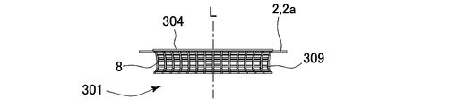
図4A及びB並びに図5A~図5Cは実施例1の眼内レンズ1の変形例1~3を示す眼内レンズ101、201、301である。以下において実施例1と同様の構成は同一の符号を付して説明を省略する。図4Aに示すように眼内レンズ101は、軸線L回りに2本の脚3aを有する。脚3aの他端部6には、軸線L回りにおける鈍角の範囲内に渡って等間隔に隣接した複数の単位鉤部8と、複数の単位鉤部8を端部11aで連結する連結部109を有する鉤部104が備わる。眼内レンズ101は、軸線Lの軸回りに鈍角に広がって複数配置された単位鉤部8(鉤部104)により眼内に安定して保持される。
図4Bに示すように眼内レンズ201は、軸線L回りに放射状に複数の脚3aを有する。脚3aの他端部6には、軸線L回りにおける鋭角の範囲内に渡って等間隔に隣接した複数の単位鉤部8と、複数の単位鉤部8を端部11aで連結する連結部209を有する鉤部204が備わる。脚3aが放射状にレンズ2に連結されるため、視軸C(軸線L)回りに環状に位置する毛様体突起21の動きを、鉤部204を通して細かにレンズ2に伝達することが可能となる。
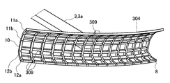
図5A~図5Cに示すように眼内レンズ301は、軸線L回りに2本の脚3aを有する。脚3aの一端部6には、軸線L回りにおける鋭角の範囲内に渡って等間隔に隣接した複数の単位鉤部8と、複数の単位鉤部8を端部11aで連結する連結部309を有する鉤部304が備わる。図5Cに示すように連結部309は複数の各単位鉤部8の端部11a、12a、屈曲部11b、12b、中間部10をそれぞれ連結し、鉤部304は全体として網状に形成される。よって、鉤部304の強度を高めることができる。
以上、水晶体14を全て摘出した患者の眼内に装着する眼内レンズ1、101、201、301の実施例1、変形例1~3を説明した。実施例1では、水晶体14を全て摘出した例を説明したが、実施例2では、前嚢15の一部と後嚢16を残して水晶体14を摘出した患者の眼内に装着する眼内レンズを説明する。
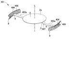
図6A~図6Dに示すように実施例2の眼内レンズ401は、軸線L回りに2本の脚403aを有する。図6Bに示すように脚部403aは、一端部5と他端部6の間でレンズ2裏面から軸線Lから離れるように斜め下方に延びた脚403aを折り曲げてレンズ2の外側に向けて導く屈曲部407を有する。図6Cに示すように脚403aの一端部6には、軸線L回りにおける鋭角θ1の範囲内に渡って等間隔に隣接した複数の単位鉤部8と、複数の単位鉤部8を上部11の端部11a(図6D参照)で連結する連結部409を有する鉤部404が備わり、図6Aに示すように鉤部404は全体として鍬状に形成される。
以上の構成を有する眼内レンズ401が白内障の患者の水晶体に代えて眼内に装着される。以下、医師が眼内レンズ401を患者の眼内に装着する一連の流れを説明する。医師は、前嚢15の一部と後嚢16を残して水晶体14を周知の方法で摘出(図7A)した後、図7Bに示すように角膜17に挿入孔23、24を形成する。その後、医師は挿入孔24からメス(図示省略)を入れて毛様体突起21に対向する嚢に眼内レンズ401の鉤部404(図6A参照)を嚢内から嚢外に出すためのスリット(図示省略)を鉤部404に対応して2箇所形成する。
医師は、挿入孔23から眼内レンズ401が収納された挿入器具Iの先端を挿入し、挿入器具Iの先端を嚢内に到達させた(図7B)後、挿入器具Iの先端から嚢内に眼内レンズ401を排出する。別途、医師は挿入孔24から鑷子(図示省略)を眼内に挿入し、眼内に排出された眼内レンズ401の脚403aを摘み、スリット(図示省略)から鉤部404を嚢外に抜き出す。次いで医師は略C字の単位鉤部8の上部11と下部12(図2A参照)に挟まれる空間内に向けて毛様体突起21に向けて強制的に押し込むように鉤部404を毛様体突起21に押し当て、鉤部404に毛様体突起21を嵌め込む。他方の脚403aについても同様の操作を医師が繰り返し、眼内レンズ401が眼内に保持される(図7C)。医師が、鉤部404を毛様体突起21に引っ掛ける際に、チン氏帯22が邪魔をする場合は、邪魔をするチン氏帯22を切除してもよい。なお、複数の単位鉤部8を中間部10で連結する連結部を有する鉤部を採用すると、鉤部を毛様体突起21に嵌め込む際に連結部がチン氏帯22に邪魔され難くなる。
図7Dに示すように鉤部404が毛様体突起21に取り付けられた状態で、毛様体突起21から嚢に繋がるチン氏帯22が隣接する単位鉤部8の間の隙間に位置する。そのため、チン氏帯22を維持したまま眼内レンズ401を毛様体突起21に装着することが可能となる。
以上のように眼内レンズ401は、鉤部404により眼内に保持される。図7Cに示すように鉤部404は、毛様体20の弛緩・収縮運動に対応して動作する毛様体突起21の外面に前嚢15の一部及び後嚢16を残した状態で嵌り込む。よって、レンズ2を毛様体20の弛緩・収縮に対応して直接的に連動させることが可能となる。レンズ2は嚢内に保持されるため、レンズ2が落下した場合の受け皿を設ける必要がない。
図6Bに示すように脚部403aは屈曲部407を有するため、屈曲部407がレンズ2の方向に押し付けられると、脚403aの一端部5がレンズ2に対して直交に近い姿勢に変化し易くなる。よって、屈曲部407の変化に応じてレンズ2が前後動し易くなる。
図8A~図8Cは実施例2の眼内レンズ401の変形例4~6を示す眼内レンズ501、601、701である。図8Aに示すように眼内レンズ501は、軸線L回りに2本の脚503aを有する。脚503aの他端部6には鉤部404が備わる。脚503aの他端部6は、鉤部404の下端部(単位鉤部8における下部12の端部12aに対応する部分)に位置し、鉤部404がレンズ2表面より上方に位置するように脚503aの一端部5がレンズ2に接続する。そのため、眼内レンズ501は、毛様体突起21よりも眼底側にレンズ2を配置できる。
図8Bに示すように眼内レンズ601は、軸線L回りに2本の脚603aを有する。脚603aの他端部6には鉤部404が備わる。脚603aの他端部6は、鉤部404の上端部(単位鉤部8における上部11の端部11aに対応する部分)に位置し、鉤部404がレンズ2裏面より下方に位置するように脚603aの一端部5がレンズ2に接続する。そのため、眼内レンズ601は、毛様体突起21よりも角膜17側(眼底と反対側)にレンズ2を配置できる。
図8Cに示すように眼内レンズ701は、軸線L回りに3本の脚703aを有する。脚703aの他端部6を鉤部404の中間部(単位鉤部8の中間部10に対応する部分)に位置する。よって、軸線L回りに等間隔に配置された3つの鉤部404でレンズ2を安定して保持できる。
上記実施例及び変形例では、眼内装着物の一例として眼内レンズを例示したが、眼内装着物としては眼内レンズ以外にもレンズが落下する受け皿など眼内に装着される種々の装着物に適用できる。
上記実施例及び変形例では単位鉤部8が毛様体突起21と接触するようにして毛様体突起21が鉤部4に嵌め込まれた例を説明したが鉤部4は必ずしも毛様体突起21に嵌め込まれる必要なない。図9Aに示すように上方に向かって延びた上部11を下方に導く端部11aと下方に向かって延びた下部12を上方に導く端部12aのみが毛様体突起21に接触した状態で鉤部4が毛様体突起21に引っ掛かりレンズ2が眼内に保持されてもよい。また、図9Bに示すように中間部10及び下部12が毛様体突起21に接触するように沿う一方で、上部11の端部11aのみが毛様体突起21に引っ掛かりレンズ2が眼内に保持されてもよい。鉤部4が毛様体突起21に引っ掛かる又は嵌った状態で被装着物が眼内に保持されればよい。
また、図9Cに示すよう端部11aは、上方に向かって延びた上部11を下方に折り返す折り返し部としてもよい。折り返し部により毛様体突起21が略C字の単位鉤部8の内部領域に挿入された際に、折り返し部が返しとなり、単位鉤部8に押し込まれた毛様体突起21が抜けるのを防止できる。押し返し部は端部12aに設けてもよい。なお、単位鉤部8の形状として、略C字を例示したが、毛様体突起21に沿うような形状ならば略C字状に限られない。
上記実施例及び変形例では円盤状のレンズ2を例示したが、レンズ2の形状としては、円盤状以外にも球面に沿う椀状や楕円板状など種々の形態を採用できる。図1Cに示すように単位鉤部8が軸線L回りに等間隔に隣接して配置される例を例示したが、隣接する単位鉤部8の間隔は等間隔でなくてもよい。鉤部4についても同様である。また、鉤部4は軸線L回りに連続して配置してもよく、連続して配置することで強固にレンズ2等の被装着物を眼内に保持できる。
上記実施例及び変形例では折れ曲がった上側屈曲部11b、下側屈曲部12bを例示したが、湾曲して曲がった上側曲げ部、下側曲げ部としてもよい。湾曲することで単位鉤部と毛様体突起21との密着度を向上させることが可能となる。
上記実施例及び変形例では、鉤部として櫛状、網状及び鍬状に形成された例を説明したが毛様体突起21の外面に沿って毛様体突起21の一部又は全部を覆う帯状に形成されてもよい。また、鉤部は柵状に形成されてもよい。鉤部4が毛様体突起21の外面に沿って延びる基点となる毛様体突起21の根元部21aとしては、鉤部4が毛様体突起21に引っ掛かる又は嵌り込むことができれば、毛様体突起21の根元に限らない。根元部としては、例えば、毛様体突起21の根元と先端の間に位置する中腹部でもよい。毛様体突起に沿って延びた鉤部4の終端についても同様である。
以上、本発明の実施の態様を説明したが、本発明はその具体的な記載に限定されることなく、例示した構成、処理等を技術的に矛盾のない範囲で適宜組み合わせて実施することも可能であるし、またある要素、処理を周知の形態に置き換えて実施することもできる。
上記の説明では、毛様体20の弛緩・収縮にともない、毛様体突起21が図3Dに示すように斜め上方に動くことを前提に説明をした。しかし、本発明者らの知見によると、毛様体20の弛緩・収縮にともない、毛様体突起21が図3Dの視軸Cに向かって横方向に動く可能性も考えられる。この場合には、視軸Cに向かって横方向に動く毛様体突起21とともに、毛様体突起21に装着された鉤部4、104、204、304、404(以下、「鉤部4等」とする)が連動する。
鉤部4等が横方向に動くことで、曲げ部7(図2B参照)が視軸Cに向けて押し付けられ、脚3aの一端部5がレンズ2に対してより直交に近い姿勢に変化し、レンズ2が上方に押し出される。そして、鉤部4等が元の位置に戻ると、レンズ2は下降して元の位置に戻る。このようにレンズ2を上下動させて、レンズ2により網膜上に結像させる視覚対象とレンズ2の間の距離を変化させてもよい。
1 眼内レンズ(眼内装着物) 2 レンズ(被装着物)
3 脚部 3a 脚
4 鉤部 5 一端部
6 他端部 7 曲げ部
8 単位鉤部 9 連結部
10 中間部 11 上部
12 下部 13 眼
14 水晶体 15 前嚢
16 後嚢 17 角膜
20 毛様体 21 毛様体突起
22 チン氏帯
3 脚部 3a 脚
4 鉤部 5 一端部
6 他端部 7 曲げ部
8 単位鉤部 9 連結部
10 中間部 11 上部
12 下部 13 眼
14 水晶体 15 前嚢
16 後嚢 17 角膜
20 毛様体 21 毛様体突起
22 チン氏帯
Claims (6)
- 視軸に関する周方向に位置する毛様体から前記視軸に突出する毛様体突起の根元部から前記毛様体突起の外面に沿って前記毛様体突起の先端部を経由して反対側の前記根元部に延びる鉤部と、
前記鉤部から前記視軸に向けて延びる脚部と、
前記脚部に支持されて眼内に装着される被装着物と、を備え、
前記鉤部が前記毛様体突起に引っ掛かった又は嵌った状態で前記被装着物が前記眼内に保持されることを特徴とする眼内装着物。 - 前記鉤部は、
前記毛様体突起に沿って前記根元部から前記先端部を経由して前記反対側の前記根元部に延びる単位鉤部を前記視軸回りに隣接して形成した複数の前記単位鉤部と、
隣接した複数の前記単位鉤部を連結する連結部と、
を備える請求項1に記載の眼内装着物。 - 前記連結部は隣接した複数の前記単位鉤部を櫛状又は網状に連結する請求項2に記載の眼内装着物。
- 眼内に装着される被装着物を支持する脚部に接続され、前記被装着物を前記眼内に保持する眼内装着物の保持部材であって、
視軸に関する周方向に位置する毛様体から前記視軸に突出する毛様体突起の根元部から前記毛様体突起の外面に沿って前記毛様体突起の先端部を経由して反対側の前記根元部に延びる鉤部を備え、
前記鉤部が前記毛様体突起に引っ掛かった又は嵌った状態で前記被装着物が前記眼内に保持されることを特徴とする眼内装着物の保持部材。 - 前記鉤部は、
前記毛様体突起に沿って前記根元部から前記先端部を経由して前記反対側の前記根元部に延びる単位鉤部を前記視軸回りに隣接して形成した複数の前記単位鉤部と、
隣接した複数の前記単位鉤部を連結する連結部と、
を備える請求項4に記載の眼内装着物の保持部材。 - 前記連結部は隣接した複数の前記単位鉤部を櫛状又は網状に連結する請求項5に記載の眼内装着物の保持部材。
Priority Applications (2)
| Application Number | Priority Date | Filing Date | Title |
|---|---|---|---|
| EP16830223.0A EP3329880B1 (en) | 2015-07-27 | 2016-06-29 | Intraocularly-mounted object and intraocularly-inserted object holding member |
| US15/739,326 US10271944B2 (en) | 2015-07-27 | 2016-06-29 | Intraocularly-mounted object and intraocularly-mounted object holding member |
Applications Claiming Priority (2)
| Application Number | Priority Date | Filing Date | Title |
|---|---|---|---|
| JP2015147498A JP6023283B1 (ja) | 2015-07-27 | 2015-07-27 | 眼内装着物及び眼内装着物の保持部材 |
| JP2015-147498 | 2015-07-27 |
Publications (1)
| Publication Number | Publication Date |
|---|---|
| WO2017018118A1 true WO2017018118A1 (ja) | 2017-02-02 |
Family
ID=57247515
Family Applications (1)
| Application Number | Title | Priority Date | Filing Date |
|---|---|---|---|
| PCT/JP2016/069228 Ceased WO2017018118A1 (ja) | 2015-07-27 | 2016-06-29 | 眼内装着物及び眼内装着物の保持部材 |
Country Status (4)
| Country | Link |
|---|---|
| US (1) | US10271944B2 (ja) |
| EP (1) | EP3329880B1 (ja) |
| JP (1) | JP6023283B1 (ja) |
| WO (1) | WO2017018118A1 (ja) |
Cited By (2)
| Publication number | Priority date | Publication date | Assignee | Title |
|---|---|---|---|---|
| US11666112B2 (en) | 2019-11-27 | 2023-06-06 | Final Forge, LLC | Headborne attachment platform including system, devices and methods |
| US12550964B2 (en) | 2023-04-27 | 2026-02-17 | Final Forge, LLC | Helmet having visor pivoting and locking mechanism and associated system and methods |
Families Citing this family (4)
| Publication number | Priority date | Publication date | Assignee | Title |
|---|---|---|---|---|
| WO2020086312A1 (en) | 2018-10-23 | 2020-04-30 | The Board Of Trustees Of The Leland Stanford Junior University | Intraocular artificial lens capsule |
| WO2021050852A1 (en) * | 2019-09-12 | 2021-03-18 | Foulkes Richard B | An intraocular clipping device |
| US12419736B2 (en) | 2020-04-29 | 2025-09-23 | Long Bridge Medical, Inc. | Devices to support and position an intraocular lens within the eye and methods of use |
| US11759309B2 (en) | 2020-04-29 | 2023-09-19 | Long Bridge Medical, Inc. | Devices to support and position an intraocular lens within the eye and methods of use |
Citations (2)
| Publication number | Priority date | Publication date | Assignee | Title |
|---|---|---|---|---|
| WO2003017873A1 (en) * | 2001-08-31 | 2003-03-06 | Ehud Assia | Implantable intraocular accommodative addition |
| JP2006288770A (ja) * | 2005-04-11 | 2006-10-26 | Kenji Yoshida | 人工水晶体 |
Family Cites Families (10)
| Publication number | Priority date | Publication date | Assignee | Title |
|---|---|---|---|---|
| US4244060A (en) * | 1978-12-01 | 1981-01-13 | Hoffer Kenneth J | Intraocular lens |
| US5769890B1 (en) * | 1997-01-16 | 2000-09-05 | Surgical Concepts Inc | Placement of second artificial lens in eye to correct for optical defects of first artificial lens in eye |
| US7037338B2 (en) * | 2001-12-14 | 2006-05-02 | Toshiyuki Nagamoto | Intraocular ring assembly and artificial lens kit |
| EP1890650A2 (en) | 2005-03-30 | 2008-02-27 | Nulens Ltd | Accommodating intraocular lens (aiol) assemblies, and discrete components therfor |
| WO2012023133A1 (en) * | 2010-08-15 | 2012-02-23 | Nulens Ltd | Discrete pre-assembled monolithic aiol assemblages and aiol assemblies including same |
| US20120253459A1 (en) * | 2011-02-04 | 2012-10-04 | Cary Reich | Intraocular accommodating lens and methods of use |
| JP5398089B2 (ja) * | 2011-12-16 | 2014-01-29 | 株式会社中京メディカル | 眼内レンズ |
| US20130304206A1 (en) * | 2012-05-10 | 2013-11-14 | Ioannis Pallikaris | Intraocular Device to Restore Natural Capsular Tension after Cataract Surgery |
| JP5475087B1 (ja) * | 2012-11-01 | 2014-04-16 | 株式会社中京メディカル | 眼内移植物、眼内移植物セット、眼内レンズ |
| EP3244832A1 (en) * | 2015-01-16 | 2017-11-22 | Marwan Ghabra | Variable strength intraocular lens and method of using same |
-
2015
- 2015-07-27 JP JP2015147498A patent/JP6023283B1/ja not_active Expired - Fee Related
-
2016
- 2016-06-29 US US15/739,326 patent/US10271944B2/en active Active
- 2016-06-29 EP EP16830223.0A patent/EP3329880B1/en active Active
- 2016-06-29 WO PCT/JP2016/069228 patent/WO2017018118A1/ja not_active Ceased
Patent Citations (2)
| Publication number | Priority date | Publication date | Assignee | Title |
|---|---|---|---|---|
| WO2003017873A1 (en) * | 2001-08-31 | 2003-03-06 | Ehud Assia | Implantable intraocular accommodative addition |
| JP2006288770A (ja) * | 2005-04-11 | 2006-10-26 | Kenji Yoshida | 人工水晶体 |
Non-Patent Citations (1)
| Title |
|---|
| See also references of EP3329880A4 * |
Cited By (2)
| Publication number | Priority date | Publication date | Assignee | Title |
|---|---|---|---|---|
| US11666112B2 (en) | 2019-11-27 | 2023-06-06 | Final Forge, LLC | Headborne attachment platform including system, devices and methods |
| US12550964B2 (en) | 2023-04-27 | 2026-02-17 | Final Forge, LLC | Helmet having visor pivoting and locking mechanism and associated system and methods |
Also Published As
| Publication number | Publication date |
|---|---|
| EP3329880B1 (en) | 2020-07-29 |
| US20180185138A1 (en) | 2018-07-05 |
| JP2017023577A (ja) | 2017-02-02 |
| JP6023283B1 (ja) | 2016-11-09 |
| EP3329880A1 (en) | 2018-06-06 |
| US10271944B2 (en) | 2019-04-30 |
| EP3329880A4 (en) | 2019-01-23 |
Similar Documents
| Publication | Publication Date | Title |
|---|---|---|
| JP6023283B1 (ja) | 眼内装着物及び眼内装着物の保持部材 | |
| US8123804B2 (en) | Intraocular lens insertion tool | |
| RU2650203C2 (ru) | Устройства расширяющихся офтальмологических имплантатов | |
| JP5481588B1 (ja) | 調節眼内レンズ | |
| US9333072B2 (en) | Intraocular lens | |
| JP5798671B1 (ja) | 眼内レンズ | |
| JP6023378B1 (ja) | 眼内レンズ及び眼内レンズのハプティック | |
| JP2010520007A (ja) | 一体型調節式眼内レンズ(aiol)及び同レンズと共に使用するための別個のベース部材 | |
| AU1964101A (en) | Collars for intraocular lens loops | |
| KR20090045315A (ko) | 안정화된 원근조절용 안내 렌즈 | |
| JP2016500291A (ja) | 嚢混濁を阻止し、嚢を安定させるためのカプセルエキスパンダーデバイス、システム、および方法 | |
| CN103476371A (zh) | 用于治疗青光眼的植入体 | |
| KR20220151230A (ko) | 안구내 인공수정체 콘택트 렌즈와 관련 시스템 및 방법 | |
| US9326845B2 (en) | Intraocular implant, intraocular implant set and intraocular lens | |
| JP2023178513A (ja) | 水晶体嚢の再建法及び緊張用装置 | |
| EP1747769A2 (en) | Intraocular devices | |
| JP2018534103A (ja) | 体液を循環させるための導管における植込み用の弾性リングおよび関連する治療装置 | |
| EP3010444B1 (en) | Haptics for intraocular devices | |
| JP5475087B1 (ja) | 眼内移植物、眼内移植物セット、眼内レンズ | |
| US4778464A (en) | Intraocular prosthetic lens | |
| EP3468513B1 (en) | Devices and systems for trabecular meshwork extension | |
| JP5436618B2 (ja) | 眼内レンズ | |
| CN114302696A (zh) | 具有特定的三维弯曲的袢元件的人工晶状体 | |
| KR102678118B1 (ko) | 홍채확장기 |
Legal Events
| Date | Code | Title | Description |
|---|---|---|---|
| 121 | Ep: the epo has been informed by wipo that ep was designated in this application |
Ref document number: 16830223 Country of ref document: EP Kind code of ref document: A1 |
|
| NENP | Non-entry into the national phase |
Ref country code: DE |
|
| WWE | Wipo information: entry into national phase |
Ref document number: 2016830223 Country of ref document: EP |