WO2017018490A1 - 車両用発光装置 - Google Patents
車両用発光装置 Download PDFInfo
- Publication number
- WO2017018490A1 WO2017018490A1 PCT/JP2016/072215 JP2016072215W WO2017018490A1 WO 2017018490 A1 WO2017018490 A1 WO 2017018490A1 JP 2016072215 W JP2016072215 W JP 2016072215W WO 2017018490 A1 WO2017018490 A1 WO 2017018490A1
- Authority
- WO
- WIPO (PCT)
- Prior art keywords
- light
- light emitting
- lens
- emitting device
- vehicle
- Prior art date
- Legal status (The legal status is an assumption and is not a legal conclusion. Google has not performed a legal analysis and makes no representation as to the accuracy of the status listed.)
- Ceased
Links
Images


Classifications
-
- F—MECHANICAL ENGINEERING; LIGHTING; HEATING; WEAPONS; BLASTING
- F21—LIGHTING
- F21S—NON-PORTABLE LIGHTING DEVICES; SYSTEMS THEREOF; VEHICLE LIGHTING DEVICES SPECIALLY ADAPTED FOR VEHICLE EXTERIORS
- F21S43/00—Signalling devices specially adapted for vehicle exteriors, e.g. brake lamps, direction indicator lights or reversing lights
- F21S43/10—Signalling devices specially adapted for vehicle exteriors, e.g. brake lamps, direction indicator lights or reversing lights characterised by the light source
- F21S43/13—Signalling devices specially adapted for vehicle exteriors, e.g. brake lamps, direction indicator lights or reversing lights characterised by the light source characterised by the type of light source
- F21S43/14—Light emitting diodes [LED]
-
- B—PERFORMING OPERATIONS; TRANSPORTING
- B60—VEHICLES IN GENERAL
- B60Q—ARRANGEMENT OF SIGNALLING OR LIGHTING DEVICES, THE MOUNTING OR SUPPORTING THEREOF OR CIRCUITS THEREFOR, FOR VEHICLES IN GENERAL
- B60Q1/00—Arrangement of optical signalling or lighting devices, the mounting or supporting thereof or circuits therefor
- B60Q1/26—Arrangement of optical signalling or lighting devices, the mounting or supporting thereof or circuits therefor the devices being primarily intended to indicate the vehicle, or parts thereof, or to give signals, to other traffic
- B60Q1/2619—Arrangement of optical signalling or lighting devices, the mounting or supporting thereof or circuits therefor the devices being primarily intended to indicate the vehicle, or parts thereof, or to give signals, to other traffic built in the vehicle body
- B60Q1/2623—Details of the fastening means
- B60Q1/263—Snap-in fasteners
-
- B—PERFORMING OPERATIONS; TRANSPORTING
- B60—VEHICLES IN GENERAL
- B60Q—ARRANGEMENT OF SIGNALLING OR LIGHTING DEVICES, THE MOUNTING OR SUPPORTING THEREOF OR CIRCUITS THEREFOR, FOR VEHICLES IN GENERAL
- B60Q1/00—Arrangement of optical signalling or lighting devices, the mounting or supporting thereof or circuits therefor
- B60Q1/26—Arrangement of optical signalling or lighting devices, the mounting or supporting thereof or circuits therefor the devices being primarily intended to indicate the vehicle, or parts thereof, or to give signals, to other traffic
- B60Q1/2696—Mounting of devices using LEDs
-
- F—MECHANICAL ENGINEERING; LIGHTING; HEATING; WEAPONS; BLASTING
- F21—LIGHTING
- F21S—NON-PORTABLE LIGHTING DEVICES; SYSTEMS THEREOF; VEHICLE LIGHTING DEVICES SPECIALLY ADAPTED FOR VEHICLE EXTERIORS
- F21S41/00—Illuminating devices specially adapted for vehicle exteriors, e.g. headlamps
- F21S41/10—Illuminating devices specially adapted for vehicle exteriors, e.g. headlamps characterised by the light source
- F21S41/14—Illuminating devices specially adapted for vehicle exteriors, e.g. headlamps characterised by the light source characterised by the type of light source
- F21S41/141—Light emitting diodes [LED]
- F21S41/147—Light emitting diodes [LED] the main emission direction of the LED being angled to the optical axis of the illuminating device
- F21S41/148—Light emitting diodes [LED] the main emission direction of the LED being angled to the optical axis of the illuminating device the main emission direction of the LED being perpendicular to the optical axis
-
- F—MECHANICAL ENGINEERING; LIGHTING; HEATING; WEAPONS; BLASTING
- F21—LIGHTING
- F21S—NON-PORTABLE LIGHTING DEVICES; SYSTEMS THEREOF; VEHICLE LIGHTING DEVICES SPECIALLY ADAPTED FOR VEHICLE EXTERIORS
- F21S41/00—Illuminating devices specially adapted for vehicle exteriors, e.g. headlamps
- F21S41/10—Illuminating devices specially adapted for vehicle exteriors, e.g. headlamps characterised by the light source
- F21S41/14—Illuminating devices specially adapted for vehicle exteriors, e.g. headlamps characterised by the light source characterised by the type of light source
- F21S41/141—Light emitting diodes [LED]
- F21S41/151—Light emitting diodes [LED] arranged in one or more lines
-
- F—MECHANICAL ENGINEERING; LIGHTING; HEATING; WEAPONS; BLASTING
- F21—LIGHTING
- F21S—NON-PORTABLE LIGHTING DEVICES; SYSTEMS THEREOF; VEHICLE LIGHTING DEVICES SPECIALLY ADAPTED FOR VEHICLE EXTERIORS
- F21S41/00—Illuminating devices specially adapted for vehicle exteriors, e.g. headlamps
- F21S41/30—Illuminating devices specially adapted for vehicle exteriors, e.g. headlamps characterised by reflectors
- F21S41/32—Optical layout thereof
- F21S41/36—Combinations of two or more separate reflectors
-
- F—MECHANICAL ENGINEERING; LIGHTING; HEATING; WEAPONS; BLASTING
- F21—LIGHTING
- F21S—NON-PORTABLE LIGHTING DEVICES; SYSTEMS THEREOF; VEHICLE LIGHTING DEVICES SPECIALLY ADAPTED FOR VEHICLE EXTERIORS
- F21S43/00—Signalling devices specially adapted for vehicle exteriors, e.g. brake lamps, direction indicator lights or reversing lights
- F21S43/10—Signalling devices specially adapted for vehicle exteriors, e.g. brake lamps, direction indicator lights or reversing lights characterised by the light source
- F21S43/13—Signalling devices specially adapted for vehicle exteriors, e.g. brake lamps, direction indicator lights or reversing lights characterised by the light source characterised by the type of light source
- F21S43/15—Strips of light sources
-
- F—MECHANICAL ENGINEERING; LIGHTING; HEATING; WEAPONS; BLASTING
- F21—LIGHTING
- F21S—NON-PORTABLE LIGHTING DEVICES; SYSTEMS THEREOF; VEHICLE LIGHTING DEVICES SPECIALLY ADAPTED FOR VEHICLE EXTERIORS
- F21S43/00—Signalling devices specially adapted for vehicle exteriors, e.g. brake lamps, direction indicator lights or reversing lights
- F21S43/10—Signalling devices specially adapted for vehicle exteriors, e.g. brake lamps, direction indicator lights or reversing lights characterised by the light source
- F21S43/19—Attachment of light sources or lamp holders
-
- F—MECHANICAL ENGINEERING; LIGHTING; HEATING; WEAPONS; BLASTING
- F21—LIGHTING
- F21S—NON-PORTABLE LIGHTING DEVICES; SYSTEMS THEREOF; VEHICLE LIGHTING DEVICES SPECIALLY ADAPTED FOR VEHICLE EXTERIORS
- F21S43/00—Signalling devices specially adapted for vehicle exteriors, e.g. brake lamps, direction indicator lights or reversing lights
- F21S43/20—Signalling devices specially adapted for vehicle exteriors, e.g. brake lamps, direction indicator lights or reversing lights characterised by refractors, transparent cover plates, light guides or filters
- F21S43/26—Refractors, transparent cover plates, light guides or filters not provided in groups F21S43/235 - F21S43/255
-
- F—MECHANICAL ENGINEERING; LIGHTING; HEATING; WEAPONS; BLASTING
- F21—LIGHTING
- F21S—NON-PORTABLE LIGHTING DEVICES; SYSTEMS THEREOF; VEHICLE LIGHTING DEVICES SPECIALLY ADAPTED FOR VEHICLE EXTERIORS
- F21S43/00—Signalling devices specially adapted for vehicle exteriors, e.g. brake lamps, direction indicator lights or reversing lights
- F21S43/30—Signalling devices specially adapted for vehicle exteriors, e.g. brake lamps, direction indicator lights or reversing lights characterised by reflectors
- F21S43/31—Optical layout thereof
-
- F—MECHANICAL ENGINEERING; LIGHTING; HEATING; WEAPONS; BLASTING
- F21—LIGHTING
- F21S—NON-PORTABLE LIGHTING DEVICES; SYSTEMS THEREOF; VEHICLE LIGHTING DEVICES SPECIALLY ADAPTED FOR VEHICLE EXTERIORS
- F21S43/00—Signalling devices specially adapted for vehicle exteriors, e.g. brake lamps, direction indicator lights or reversing lights
- F21S43/40—Signalling devices specially adapted for vehicle exteriors, e.g. brake lamps, direction indicator lights or reversing lights characterised by the combination of reflectors and refractors
-
- F—MECHANICAL ENGINEERING; LIGHTING; HEATING; WEAPONS; BLASTING
- F21—LIGHTING
- F21V—FUNCTIONAL FEATURES OR DETAILS OF LIGHTING DEVICES OR SYSTEMS THEREOF; STRUCTURAL COMBINATIONS OF LIGHTING DEVICES WITH OTHER ARTICLES, NOT OTHERWISE PROVIDED FOR
- F21V5/00—Refractors for light sources
-
- F—MECHANICAL ENGINEERING; LIGHTING; HEATING; WEAPONS; BLASTING
- F21—LIGHTING
- F21Y—INDEXING SCHEME ASSOCIATED WITH SUBCLASSES F21K, F21L, F21S and F21V, RELATING TO THE FORM OR THE KIND OF THE LIGHT SOURCES OR OF THE COLOUR OF THE LIGHT EMITTED
- F21Y2103/00—Elongate light sources, e.g. fluorescent tubes
- F21Y2103/10—Elongate light sources, e.g. fluorescent tubes comprising a linear array of point-like light-generating elements
-
- F—MECHANICAL ENGINEERING; LIGHTING; HEATING; WEAPONS; BLASTING
- F21—LIGHTING
- F21Y—INDEXING SCHEME ASSOCIATED WITH SUBCLASSES F21K, F21L, F21S and F21V, RELATING TO THE FORM OR THE KIND OF THE LIGHT SOURCES OR OF THE COLOUR OF THE LIGHT EMITTED
- F21Y2115/00—Light-generating elements of semiconductor light sources
- F21Y2115/10—Light-emitting diodes [LED]
Definitions
- the present invention relates to a light emitting device for a vehicle, and more particularly to a light emitting device for a vehicle including a plurality of light sources.
- Some vehicle light-emitting devices include a plurality of light sources.
- various lighting effects may be produced by simultaneously or sequentially illuminating a plurality of light sources.
- the present invention has been made in view of the above problems, and an object of the present invention is to provide a vehicular light emitting device capable of producing an effect so that there are more light sources than the actual number of light sources and reducing unevenness in luminance. There is.
- the problem is that a plurality of light emitting units including a light source and a lens that diffuses and emits light incident from the light source are arranged side by side, and one or more luminance peak values are also present between the plurality of light emitting units. This is solved by the existing vehicle light emitting device.
- the above vehicle light-emitting device it is possible to produce more light sources than the actual number of light sources by having at least one luminance peak between a plurality of light-emitting units each having a light source. And uneven brightness can be reduced.
- the light emitted from the lens of the light-emitting unit has a plurality of luminance peaks with respect to a light spreading direction, and a plurality of light emitted from the plurality of light-emitting units.
- the arrangement intervals of the plurality of light emitting units may be set so that luminance peaks are arranged at substantially equal intervals.
- the luminance peaks of the light emitted from the plurality of light emitting units are substantially equidistant, so that the luminance unevenness can be further reduced.
- the vehicle light-emitting device may include a holding unit that holds the plurality of light-emitting units, and the holding unit may include a reflecting unit that reflects light emitted from the lens toward a light-emitting surface. Thereby, the irradiation direction of light can be adjusted.
- the reflecting portion may be formed with a convex portion at a position facing the light source. Thereby, the reflection direction of the light in a reflection part can be adjusted, and also brightness nonuniformity can be reduced.
- the holding portion may be formed with a recess between regions where the plurality of light emitting units are held.
- the lens may have a locking claw portion at both ends, and may be snap-fixed to the holding portion by the locking claw portion. Thereby, a lens can be stably attached to a holding part.
- the lens may be provided with a rib for restricting rotation with respect to the holding portion.
- the lens may have a notch formed at a position facing the light source. Thereby, the light incident on the lens can be refracted in the diffusing direction.
- the lens may include a light source introduction portion provided on both sides of the notch and protruding toward the light source.
- the luminance peaks of light emitted from a plurality of light emitting units are substantially equally spaced, so that the luminance unevenness can be further reduced.
- the direction of light irradiation can be adjusted.
- light can be prevented from diffusing to the cover side.
- the rotation of the lens with respect to the holding portion is restricted, the light irradiation direction can be stabilized.
- light incident on a lens can be refracted in a diffusing direction.
- the positioning accuracy between the light source and the lens can be improved.
- FIG. 8 is a sectional view taken along line VII-VII in FIG. 7.
- the structural example of the lens at the time of providing a rotation control mechanism is shown, (A) is a top view of the light emission unit containing a lens, (B) is a side view of (A). It is a figure explaining the shape of the light emission unit group which connected the several light emission unit. It is a top view of the light-emitting device for vehicles concerning a 3rd embodiment. It is XI-XI sectional drawing of FIG. It is a figure which shows the characteristic of the luminance peak of the light emission unit which concerns on 3rd Embodiment. It is a figure which shows the characteristic of the luminance peak of the several light emission unit by which the arrangement
- a plurality of light emitting units including a light source and a lens that diffuses and emits light incident from the light source are arranged side by side, and one luminance peak value is also present between the plurality of light emitting units.
- the present invention relates to an invention of a light emitting device for vehicles that exists as described above.
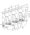
- FIG. 1 is a plan view of a light emitting device 1 for a vehicle according to the first embodiment.
- 2 is a cross-sectional view taken along the line II-II in FIG.
- FIG. 3 is a perspective view of the vehicle light emitting device 1 with the cover 50 removed.
- the lens 30 includes a lens body portion 31, a notch portion 32, a light source introduction portion 33, and an attachment structure portion 34.
- the notch 32 is provided at a position in the center of the lens body 31 and facing the LED unit 20.
- the light source introduction part 33 projects toward the LED part 20 on the rear side of the notch part 32 and introduces incident light from the LED part 20.
- the attachment structure portion 34 is a portion that protrudes outward from both sides of the lens main body portion 31 and attaches the lens 30 to the holder 10.
- a locking claw portion 35 is provided at the rear side end portion of the attachment structure portion 34, and the lens 30 is snap-fit fixed to the holder 10 by the locking claw portion 35.
- the curvature of the notch 32 is larger than the curvature of the front edge of the lens body 31 (for example, the average curvature).
- the curvature of the front edge part of the lens main-body part 31 may be constant, and may not be constant. When it is not constant, for example, the curvature at the center of the front edge may be made smaller than the curvature outside the center.
- the LED part 20 is each arrange
- the light emitting unit 100 is used.
- the series direction is a direction in which the central axis of the lens 30 and the optical axis of the LED unit 20 are parallel (including coincidence).
- the light emitting unit 100 can be thinned by configuring the light emitting unit 100 by arranging the LED unit 20 and the lens 30 in series. By mounting such a thin light-emitting unit 100, the vehicle light-emitting device 1 can be thinned, so that the degree of freedom of installation in the vehicle can be increased.
- the vehicle light-emitting device 1 includes a plurality of light-emitting units 100.
- the plurality of light emitting units 100 are arranged in parallel with the longitudinal direction of the window portion 51.
- the light emitting unit 100 adjacent to the light emitting unit 100 is provided with a convex portion 12 at a position facing the light emitting unit 100 (that is, the LED unit 20) in the reflecting portion 11.
- a plane portion 13 is provided between the positions facing each other (that is, between the convex portion 12 and the convex portion 12).
- the cover 50 has a shape inclined toward the lens 30 from the rear to the front of the lens 30.
- the cover 50 and the lens 30 are closest to each other at the front end portion of the lens 30.
- emitted from the front edge part of the lens 30 reflects in the cover 50, and returns to the back side rather than the window part 51.
- FIG. Thereby, it can suppress that the brightness
- the window part 51 side of the light-emitting device 1 for vehicles be a light emission surface side, and let the opposite side be a back surface side.
- the lens fixing region 18 of the holder 10 has an insertion hole 14 through which the light source introduction portion 33 of the lens 30 is inserted, and a rear end portion (locking claw) of the mounting structure portion 34 of the lens 30. Insertion holes 15 through which the portion 35 is inserted are provided.
- FIG. 5 shows luminance characteristics when a plurality of light emitting units 100 are arranged at a predetermined arrangement interval (D).
- FIG. 5 shows the relationship between the position on the light emitting surface on the front side of the plurality of light emitting units 100 and the luminance.
- the luminance peaks on the light emitting surface can be made substantially equal.
- a peak also exists between the positions facing the light emitting units 100 on the light emitting surface.
- luminance unevenness can be further reduced by setting the luminance peaks at substantially equal intervals.
- FIG. 6 is a plan view of the vehicle light emitting device 1A according to the second embodiment.
- 7 is a sectional view taken along line VII-VII in FIG.
- the light emitting unit 100 mounted on the vehicle light emitting device 1A according to the second embodiment is the same as that of the first embodiment, and thus the description thereof is omitted. In the following, differences from the first embodiment will be mainly described.
- the structure of the cover 50A and the holder 10A is different from that of the vehicle light emitting device 1 according to the first embodiment. That is, as shown in FIG. 7, in the second embodiment, the light emitting unit 100 and the window portion 51A of the cover 50A are disposed in series, and the holder 10A is not provided with the reflection portion forming region 19. This is different from the first embodiment. Furthermore, in the second embodiment, the bowl-shaped recess 60 is formed on the light emitting surface side of the base (holder base region 16A) of the holder 10A and on the surface between the adjacent light emitting units 100. This is different from the first embodiment. The recess 60 is formed so that the width gradually decreases from the front end of the holder base region 16A to the center position of the lens 30.
- FIG. 8 shows a configuration example of the lens 30 when the lens 30 is provided with a rotation restricting mechanism for the holder 10.
- 8A shows a plan view of the light emitting unit 100 including the lens 30 fixed to the holder 10
- FIG. 8B shows a side view of FIG. 8A.
- ribs 36 projecting vertically from the attachment structure 34 are provided on both surfaces of the attachment structure 34 of the lens 30 of the light emitting unit 100.
- the rib 36 functions to regulate the swinging motion of the lens 30 relative to the holder 10 by the rib 36 of the lens 30 abutting against the lens fixing region 18 of the holder 10.
- the above swinging motion refers to a rotational motion in which the front end portion of the lens 30 approaches or moves away from the holder base region 16.
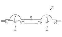
- FIG. 9 An example of a structure in which a single light emitting unit 100 is attached to the holder 10 has been described. However, as illustrated in FIG. 9, a light emitting unit group 101 in which a plurality of light emitting units 100 are connected by a connecting portion 37 is provided. You may make it attach to the holder 10.
- FIG. 9 a light emitting unit group 101 in which a plurality of light emitting units 100 are connected by a connecting portion 37 is provided. You may make it attach to the holder 10.
- FIG. 10 is a plan view of the vehicle light emitting device 1B according to the third embodiment
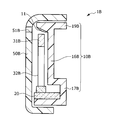
- FIG. 11 is a sectional view taken along line XI-XI in FIG.
- the vehicular light emitting device 1B mainly includes a cover 50B, an LED unit 20 serving as a light source, a lens 30B that diffuses and emits light incident from the LED unit 20, A holder 10B (holding unit) that holds the LED unit 20, the lens 30B, and the like is provided. Further, the holder 10B is provided with a reflecting portion 11 having a mirror finish. The reflection unit 11 reflects the refracted light from the lens 30 ⁇ / b> B toward the window 51 ⁇ / b> B (light emitting surface) of the cover 50.
- the lens 30 ⁇ / b> B includes a lens main body 31 ⁇ / b> B and a notch 32 ⁇ / b> B provided at the center of the lens main body 31 ⁇ / b> B and facing the LED unit 20.
- the LED unit 20 arranged in series with the lens 30B is collectively referred to as a light emitting unit 100B.
- the cover 50B has a U-shape, and the light emitting surface forming surface provided with the window 51B in the cover 50B and the lens 30B are substantially parallel to each other. Further, the length of the light emitting surface forming surface in the front-rear direction (length in the direction perpendicular to the arrangement direction of the light emitting units 100B) is longer than that in the first embodiment.
- the window 51B side of the vehicle light emitting device 1B is the light emitting surface side, and the opposite side is the back surface side.
- the holder 10 includes an LED attachment region 17B, a holder base region 16B, and a reflection portion formation region 19B.
- the LED attachment region 17B is a substantially U-shaped part to which the LED unit 20 is attached and fixed.
- the holder base region 16B is a portion that supports the lens 30B and extends from the LED attachment region 17B substantially in parallel with the lens 30B.
- the reflection portion forming region 19B is a portion that extends from the holder base region 16B to the light emitting surface side, and is a portion where the reflecting portion 11 is provided on the inclined surface that is on the light emitting surface side and faces the lens 30B.
- the angle (slope) of the reflecting surface may be set so that the intensity of the reflected light from the lens 30B to the window 51B is maximized.
- control circuit (not shown) is connected to the LED unit 20, and the light emission timing, the light emission time, and the like of each of the plurality of LED units 20 are controlled by the control circuit.
- the lens 30B mounted on the vehicle light emitting device 1B according to the third embodiment is the same as the lens 30 mounted on the vehicle light emitting device 1 according to the first embodiment.
- the lens body 31 (31B) and the notch 32 (32B) are different in the R shape. That is, in the third embodiment, the curvature of the lens body 31B is larger than the curvature of the lens body 31 in the first embodiment. Moreover, in 3rd Embodiment, the curvature of the notch part 32B is smaller than the curvature of the notch part 32 in 1st Embodiment.
- the diffusion mode of light from the lens can be adjusted and the luminance pattern can be changed.
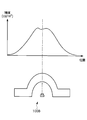
- FIG. 12 shows the luminance characteristics of a single light emitting unit 100B according to the third embodiment.
- FIG. 12 shows the relationship between the position of the light emitting surface on the front side of the single light emitting unit 100B (that is, the position in the width direction of the light emitting surface) and the luminance.
- a gentle luminance peak is present at a position passing from the LED unit 20 through the center of the notch 32 compared to the light emitting unit 100 according to the first embodiment.
- the lens 30B according to the third embodiment emits diffused light with reduced luminance unevenness as compared with the lens 30 according to the first embodiment.
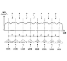
- FIG. 13 shows luminance characteristics when a plurality of light emitting units 100B according to the third embodiment are arranged at a predetermined arrangement interval (d).
- FIG. 13 shows the relationship between the light emitting surface position on the front side of the plurality of light emitting units 100B (that is, the position in the width direction of the light emitting surface) and the luminance.
- a luminance peak also exists between the positions facing the light emitting units 100B.
- luminance unevenness on the light emitting surface can be reduced.
- the diffusion mode of the light from the lens changes by changing the R shape of the lens that diffuses the light incident from the LED unit.
- the light emitting unit is downsized by making the curvature of the outer periphery of the lens smaller than that of the lens in the third embodiment. This makes it possible to reduce the size of the vehicle light emitting device on which the light emitting unit is mounted. In this way, by setting the R shape of the lens, the vehicle light emitting device in which unevenness in luminance is suppressed can be made to correspond to the size of the space required by the vehicle.
- the vehicle light-emitting device according to the first to third embodiments according to the present invention has been mainly described.
- said embodiment is only an example for making an understanding of this invention easy, and does not limit this invention.
- the present invention can be changed and improved without departing from the gist thereof, and the present invention includes the equivalents thereof.
Landscapes
- Engineering & Computer Science (AREA)
- General Engineering & Computer Science (AREA)
- Physics & Mathematics (AREA)
- Microelectronics & Electronic Packaging (AREA)
- Optics & Photonics (AREA)
- Mechanical Engineering (AREA)
- Non-Portable Lighting Devices Or Systems Thereof (AREA)
- Securing Globes, Refractors, Reflectors Or The Like (AREA)
Abstract
実際の光源数より多くの光源があるように演出可能とし輝度のムラを低減する。 車両用発光装置では、LED部20と、LED部20から入射された光を拡散して出射するレンズ30とを備える発光ユニット100が複数並んで配置される。複数の発光ユニット100の間にも輝度のピーク値が1つ以上存在する。また、発光ユニット100のレンズから出射される光は、光の広がり方向に対し複数の輝度のピークを有し、複数の発光ユニット100から出射される光の複数の輝度のピークが略等間隔に並ぶように、複数の発光ユニット100の配置間隔が設定される。
Description
本発明は、車両用発光装置に係り、特に、複数の光源を備える車両用発光装置に関する。
車両用発光装置には複数の光源を備えているものがある。こうした車両用発光装置においては、複数の光源を同時に光らせたり、順次光らせたりすることにより多様な照明効果を演出することがある。
例えば下記の特許文献1においては、複数のLEDを備える車両用発光装置において、LEDからの出射光に輝度ムラが生じることを抑えるために、各LEDからの光を反射させて広範囲に拡散させる構造を設けている。
複数の光源の輝度ムラを抑えるために、複数の光源からの光を反射させて混ざり合わせるようにすると、どの光源が光っているのかが不鮮明となり、照明の演出性が低下する虞がある。一方で、光源の数を増やすと、消費電力やコストの点で問題がある。
本発明は、上記の課題に鑑みてなされたものであり、本発明の目的は、実際の光源数より多くの光源があるように演出可能とし輝度のムラを低減できる車両用発光装置を提供することにある。
前記課題は、光源と、当該光源から入射された光を拡散して出射するレンズとを備える発光ユニットが複数並んで配置され、複数の前記発光ユニットの間にも輝度のピーク値が1つ以上存在する車両用発光装置により解決される。
上記の車両用発光装置では、それぞれ光源を備える複数の発光ユニットの間にも輝度のピークが1つ以上存在するようにしたことで、実際の光源数よりも多くの光源があるように演出可能とし、輝度のムラを低減することができる。
上記の車両用発光装置において、前記発光ユニットの前記レンズから出射される光は、光の広がり方向に対し複数の輝度のピークを有し、前記複数の前記発光ユニットから出射される光の複数の輝度のピークが略等間隔に並ぶように、前記複数の前記発光ユニットの配置間隔が設定されることとしてよい。これにより、複数の発光ユニットから照射される光の輝度のピークが略等間隔となるため、輝度のムラを更に低減することができる。
上記の車両用発光装置において、前記複数の前記発光ユニットを保持する保持部を備え、前記保持部は、前記レンズから出射された光を発光面に向けて反射する反射部を有することとしてよい。これにより、光の照射方向を調整することができる。
上記の車両用発光装置において、前記反射部は、前記光源と対向する位置に凸部が形成されることとしてよい。これにより、反射部における光の反射方向を調整することができ、更に輝度ムラも低減することができる。
上記の車両用発光装置において、前記保持部は、前記複数の前記発光ユニットを保持する領域の間に凹部が形成されることとしてよい。これにより、保持部側からの反射方向を制御し、輝度ムラを低減することができる。
上記の車両用発光装置において、前記保持部と係合し、前記複数の前記発光ユニットを覆うカバーを備え、前記カバーは、前記レンズにおける光の出射側の端部において、前記レンズとの距離が最も近くなる形状であることとしてよい。これにより、カバー側に光が拡散してしまうことを抑制できる。
上記の車両用発光装置において、前記レンズは、両端に係止爪部を有し、前記係止爪部により前記保持部にスナップ固定されることとしてよい。これにより、レンズを保持部に安定的に取り付けできる。
上記の車両用発光装置において、前記レンズは、前記保持部に対する回転を規制するリブが形成されることとしてよい。これにより、レンズの保持部に対する回転が規制されるため、光の照射方向を安定させることができる。さらに、車両の振動時のレンズの動きも規制されるため、レンズが他の部材と衝突することによる音鳴りの発生も抑制される。
上記の車両用発光装置において、前記レンズは、前記光源と対向する位置に切欠きが形成されることとしてよい。これにより、レンズに入射する光を拡散する方向に屈折させることができる。
上記の車両用発光装置において、前記レンズは、前記切欠きの両側に設けられ、前記光源側に突出した光源導入部を有することとしてよい。これにより、レンズに対する光源の位置を定めやすくなるため、光源とレンズとの位置決め精度を向上させることができる。
本発明によれば、実際の光源数よりも多くの光源があるように演出可能となり輝度のムラを低減できる。
本発明の一側面によれば、複数の発光ユニットから照射される光の輝度のピークが略等間隔となるため、輝度のムラを更に低減できる。
本発明の一側面によれば、光の照射方向を調整できる。
本発明の一側面によれば、反射部における光の反射方向を調整でき、更に輝度ムラも低減できる。
本発明の一側面によれば、保持部側からの反射方向を制御し、輝度ムラを低減できる。
本発明の一側面によれば、カバー側に光が拡散してしまうことを抑制できる。
本発明の一側面によれば、レンズを保持部に安定的に取り付けできる。
本発明の一側面によれば、レンズの保持部に対する回転が規制されるため、光の照射方向を安定させることができる。
本発明の一側面によれば、レンズに入射する光を拡散する方向に屈折させることができる。
本発明の一側面によれば、レンズに対する光源の位置を定めやすくなるため、光源とレンズとの位置決め精度を向上させることができる。
以下、本発明の実施形態に係る車両用発光装置について、図1~図13を参照しながら説明する。
本実施形態は、光源と、当該光源から入射された光を拡散して出射するレンズとを備える発光ユニットが複数並んで配置され、複数の前記発光ユニットの間にも輝度のピーク値が1つ以上存在する車両用発光装置の発明に関するものである。
<第1の実施形態>
まず、図1~図5に基づいて、本発明の第1の実施形態に係る車両用発光装置1について説明する。
まず、図1~図5に基づいて、本発明の第1の実施形態に係る車両用発光装置1について説明する。
図1は、第1の実施形態に係る車両用発光装置1の平面図である。図2は図1のII-II断面図である。図3は車両用発光装置1のカバー50を外した状態の斜視図である。
図1に示されるように、車両用発光装置1は主に、カバー50、光源となるLED部20、LED部20から入射する光を拡散して出射させるレンズ30、LED部20及びレンズ30等を保持するホルダー10(保持部)を備えている。また、ホルダー10には、凸部12と平面部13からなる鏡面仕上げがなされた反射部11が設けられており、反射部11によりレンズ30からの屈折光をカバー50の窓部51(発光面)に向けて反射するようになっている。なお以下において、LED部20の出射方向(すなわち、LED部20から切り欠き部に向かう側)を前方、その逆を後方とし、レンズ30の中心から遠くなる側を外側、その逆を内側とする。
図1に示されるように、レンズ30は、レンズ本体部31、切欠き部32、光源導入部33、取付構造部34を備える。
切欠き部32は、レンズ本体部31の中央であってLED部20と対向する位置に設けられる。
光源導入部33は、切欠き部32の後方側においてLED部20側に突出し、LED部20からの入射光を導入する。
取付構造部34は、レンズ本体部31の両側から外側に向けて突出し、レンズ30をホルダー10に取り付ける部分である。
なお、取付構造部34の後側方端部には、係止爪部35が設けられており、係止爪部35によりレンズ30がホルダー10にスナップフィット固定されるようになっている。
切欠き部32は、レンズ本体部31の中央であってLED部20と対向する位置に設けられる。
光源導入部33は、切欠き部32の後方側においてLED部20側に突出し、LED部20からの入射光を導入する。
取付構造部34は、レンズ本体部31の両側から外側に向けて突出し、レンズ30をホルダー10に取り付ける部分である。
なお、取付構造部34の後側方端部には、係止爪部35が設けられており、係止爪部35によりレンズ30がホルダー10にスナップフィット固定されるようになっている。
ここで、図1に示されるように、レンズ本体部31の前方縁部の曲率(例えば平均曲率)に対して、切欠き部32の曲率の方が大きくなっている。なお、レンズ本体部31の前方縁部の曲率は一定であってもよいし、一定でなくてもよい。一定でない場合には、例えば、前方縁部の中央の曲率を、中央よりも外側の曲率よりも小さくすることとしてもよい。
また、図1乃至図3に示されるように、複数のレンズ30に対してそれぞれLED部20が1つ直列方向に配置されており、LED部20と直列に配置されたレンズ30とを合わせて発光ユニット100とする。上記の直列方向とは、レンズ30の中心軸と、LED部20の光軸とが並行(一致も含む)となる方向である。
このように、LED部20とレンズ30を直列配置して発光ユニット100を構成することにより、発光ユニット100を薄型化することができる。
こうした薄型の発光ユニット100を搭載することで、車両用発光装置1を薄型化することができるため、車両への設置の自由度を高めることができる。
このように、LED部20とレンズ30を直列配置して発光ユニット100を構成することにより、発光ユニット100を薄型化することができる。
こうした薄型の発光ユニット100を搭載することで、車両用発光装置1を薄型化することができるため、車両への設置の自由度を高めることができる。
図1に示されるように、車両用発光装置1は、複数の発光ユニット100を備えている。複数の発光ユニット100は、窓部51の長手方向と平行に配列されている。ここで、図1及び図3に示されるように、反射部11のうち、発光ユニット100(すなわちLED部20)に対向する位置には凸部12を設け、発光ユニット100と隣り合う発光ユニット100とにそれぞれ対向する位置の間(すなわち凸部12と凸部12の間)においては平面部13を設けている。こうすることで、反射部11における光の反射方向を調整することができ、更に輝度ムラも低減することができる。
図2に示されるように、カバー50はレンズ30の後方から前方にかけてレンズ30側に傾斜する形状となっている。特にカバー50とレンズ30とはレンズ30の前方端部において最も距離が近くなっている。これにより、レンズ30の前方端部から出射した光が、カバー50に反射して窓部51よりも後方側に戻ってしまうことを抑制できる。これにより、窓部51から車両用発光装置1の外部に照射される光の輝度を低下させてしまうことを抑制できる。なお、以下において、車両用発光装置1の窓部51側を発光面側、その反対側を裏面側とする。
また、図2に示されるように、ホルダー10は、ホルダー基部領域16、LED取付領域17、レンズ固定領域18、及び反射部形成領域19を有する。
ホルダー基部領域16は、前方から後方に延出する部分である。LED取付領域17は、ホルダー基部領域16の後方端部において裏面側に延出し、LED部20が取付固定される部分である。レンズ固定領域18は、ホルダー基部領域16から発光面側に延出し、レンズ30が取付固定される部分である。反射部形成領域19は、ホルダー基部領域16の前方端部において発光面側と裏面側の両側に延出し、発光面側であってレンズ30と対向する斜面に反射部11が設けられる部分である。
ここで、反射面の角度(斜度)は、レンズ30から窓部51への反射光の強度が最大となるように設定されることとしてよい。
ホルダー基部領域16は、前方から後方に延出する部分である。LED取付領域17は、ホルダー基部領域16の後方端部において裏面側に延出し、LED部20が取付固定される部分である。レンズ固定領域18は、ホルダー基部領域16から発光面側に延出し、レンズ30が取付固定される部分である。反射部形成領域19は、ホルダー基部領域16の前方端部において発光面側と裏面側の両側に延出し、発光面側であってレンズ30と対向する斜面に反射部11が設けられる部分である。
ここで、反射面の角度(斜度)は、レンズ30から窓部51への反射光の強度が最大となるように設定されることとしてよい。
また、図3に示されるように、ホルダー10のレンズ固定領域18には、レンズ30の光源導入部33が挿通される挿通孔14、レンズ30の取付構造部34の後方端部(係止爪部35を含む)が挿通される挿通孔15がそれぞれ設けられている。
また、LED部20には、図示しない制御回路が接続されており、制御回路により複数のLED部20のそれぞれの発光タイミング、発光時間等が制御される。これにより、複数のLED部20を同時に発光させたり、複数のLED部20の一部を発光させたり、複数のLED部20が左右に流れるよう発光させたりすることで、多様な照明効果を演出することができる。
次に、図4及び図5に基づいて、第1の実施形態に係る車両用発光装置1に備えられる発光ユニット100の輝度特性及び、複数の発光ユニット100の輝度特性について説明する。
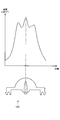
図4には、単体の発光ユニット100の輝度特性を示す。図4は、単体の発光ユニット100の前方側の発光面における位置(すなわち、発光面の幅方向における位置)と輝度の関係を示している。
図4に示されるように、発光ユニット100では、LED部20から、切欠き部32の中心を通る位置に第1の輝度ピークがあり、さらに第1の輝度ピークの左右にも2つの輝度のピーク(第2の輝度ピーク及び第3の輝度ピーク)が存在している。このように、レンズ30のレンズ本体部31の形状(特にサイズ及び曲率)と、切欠き部32の形状(特にサイズ及び曲率)に応じて、発光ユニット100から出射される光の広がり方向において、複数の輝度のピークが出現することとなる。
図4に示されるように、発光ユニット100では、LED部20から、切欠き部32の中心を通る位置に第1の輝度ピークがあり、さらに第1の輝度ピークの左右にも2つの輝度のピーク(第2の輝度ピーク及び第3の輝度ピーク)が存在している。このように、レンズ30のレンズ本体部31の形状(特にサイズ及び曲率)と、切欠き部32の形状(特にサイズ及び曲率)に応じて、発光ユニット100から出射される光の広がり方向において、複数の輝度のピークが出現することとなる。
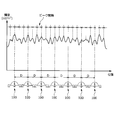
また、図5には、複数の発光ユニット100を所定の配置間隔(D)で配置した場合の輝度特性を示す。図5は、複数の発光ユニット100の前方側の発光面における位置と輝度との関係を示している。
図5に示されるように、発光ユニット100の配置間隔を調整することにより、発光面における輝度のピークが略等間隔とすることができる。このように発光ユニット100の配置間隔を調整することで、発光面において発光ユニット100に対向する位置の間にもピークが存在するようになる。これにより、発光ユニット100の数(すなわち光源の数)よりも多くの光源があるように演出可能となり、輝度ムラを低減させることができる。また、輝度のピークを略等間隔に設定することで、更に輝度ムラを低減させることもできる。
図5に示されるように、発光ユニット100の配置間隔を調整することにより、発光面における輝度のピークが略等間隔とすることができる。このように発光ユニット100の配置間隔を調整することで、発光面において発光ユニット100に対向する位置の間にもピークが存在するようになる。これにより、発光ユニット100の数(すなわち光源の数)よりも多くの光源があるように演出可能となり、輝度ムラを低減させることができる。また、輝度のピークを略等間隔に設定することで、更に輝度ムラを低減させることもできる。
<第2の実施形態>
次に、図6及び図7に基づいて、本発明の第2の実施形態に係る車両用発光装置1Aについて説明する。
次に、図6及び図7に基づいて、本発明の第2の実施形態に係る車両用発光装置1Aについて説明する。
図6は、第2の実施形態に係る車両用発光装置1Aの平面図である。図7は図6のVII-VII断面図である。なお、第2の実施形態に係る車両用発光装置1Aに搭載される発光ユニット100は第1の実施形態と同様であるため説明を省略する。以下では、第1の実施形態からの相違点を主に説明する。
図6及び図7に示されるように、第2の実施形態に係る車両用発光装置1Aでは、カバー50A及びホルダー10Aの構造が第1の実施形態に係る車両用発光装置1とは異なる。すなわち、図7に示されるように、第2の実施形態では、発光ユニット100とカバー50Aの窓部51Aが直列方向に配置されており、ホルダー10Aには反射部形成領域19が設けられていない点で第1の実施形態と差異がある。また更に、第2の実施形態では、ホルダー10Aの基部(ホルダー基部領域16A)の発光面側であって、隣り合う発光ユニット100の間の表面に、お椀状の凹部60を形成するようにした点で第1の実施形態と差異がある。なお、凹部60は、ホルダー基部領域16Aの前方端部からレンズ30の中央の位置程度にかけて、幅が徐々に小さくなるように形成される。
上記のようにホルダー基部領域16Aにお椀状の凹部60を形成することにより、ホルダー10A側からの反射方向を制御し、輝度ムラを低減することができる。
ここで、図8及び図9に基づいて、車両用発光装置1に搭載されるレンズ30の他の構成例について説明する。なお、以下に説明するレンズ30の例は、車両用発光装置1Aに対しても同様に適用可能である。
図8には、レンズ30にホルダー10に対する回転規制機構を設けた場合のレンズ30の構成例について示した。図8(A)には、ホルダー10に固定されるレンズ30を含む発光ユニット100の平面図を、図8(B)には図8(A)の側面図を示している。図8(A)及び(B)に示されるように、発光ユニット100のレンズ30における取付構造部34の両面にそれぞれ取付構造部34から垂直に突出するリブ36が設けられている。
図8(B)に示されるように、リブ36は、レンズ30のホルダー10に対する首振り動作を、レンズ30のリブ36がホルダー10のレンズ固定領域18と突き当たることで規制する機能を果たす。なお、上記の首振り動作とは、レンズ30の前方端部がホルダー基部領域16に近づいたり遠ざかったりする回転動作のことをいう。
これにより、レンズ30がホルダー10やLED部20に対して当初の配置からずれる動きを規制できるため、発光ユニット100からの照射方向を安定させることができる。さらに、レンズ30の動きが規制されているため、車両の振動時においてもレンズ30が他の部材と衝突することが抑制され、音鳴りも低減される。
これにより、レンズ30がホルダー10やLED部20に対して当初の配置からずれる動きを規制できるため、発光ユニット100からの照射方向を安定させることができる。さらに、レンズ30の動きが規制されているため、車両の振動時においてもレンズ30が他の部材と衝突することが抑制され、音鳴りも低減される。
以上の実施形態においては、単体の発光ユニット100をホルダー10に取り付ける構造の例について説明したが、図9に示されるように、複数の発光ユニット100を連結部37により連結した発光ユニット群101をホルダー10に取り付けるようにしてもよい。
<第3の実施形態>
次に、図10乃至図13に基づいて、本発明の第3の実施形態に係る車両用発光装置1Bについて説明する。
次に、図10乃至図13に基づいて、本発明の第3の実施形態に係る車両用発光装置1Bについて説明する。
図10は、第3の実施形態に係る車両用発光装置1Bの平面図であり、図11は図10のXI-XI断面図である。
図10に示されるように、第3の実施形態に係る車両用発光装置1Bは主に、カバー50B、光源となるLED部20、LED部20から入射する光を拡散して出射させるレンズ30B、LED部20及びレンズ30B等を保持するホルダー10B(保持部)を備えている。また、ホルダー10Bには、鏡面仕上げがなされた反射部11が設けられている。反射部11は、レンズ30Bからの屈折光をカバー50の窓部51B(発光面)に向けて反射するようになっている。
図10に示されるように、レンズ30Bは、レンズ本体部31B、レンズ本体部31Bの中央であってLED部20と対向する位置に設けられた切欠き部32Bを備えている。なお、以下において、レンズ30Bと直列に配置されたLED部20とを合わせて発光ユニット100Bとする。
図11に示されるように、カバー50Bはコの字形状となっており、カバー50Bのうち窓部51Bが設けられた発光面形成面とレンズ30Bとは略並行となっている。また、発光面形成面の前後方向の長さ(発光ユニット100Bの配列方向と垂直方向についての長さ)は第1の実施形態に比べて長くなっている。以下、車両用発光装置1Bの窓部51B側を発光面側、その反対側を裏面側とする。
また、図11に示されるように、ホルダー10は、LED取付領域17B、ホルダー基部領域16B、反射部形成領域19Bを有する。
LED取付領域17Bは、LED部20が取付固定される略U字形状の部分である。ホルダー基部領域16Bは、レンズ30Bを支持する、LED取付領域17Bからレンズ30Bと略並行に延出する部分である。反射部形成領域19Bは、ホルダー基部領域16Bから発光面側に延出する部分であって、発光面側であってレンズ30Bと対向する斜面に反射部11が設けられる部分である。ここで、反射面の角度(斜度)は、レンズ30Bから窓部51Bへの反射光の強度が最大となるように設定されることとしてよい。
LED取付領域17Bは、LED部20が取付固定される略U字形状の部分である。ホルダー基部領域16Bは、レンズ30Bを支持する、LED取付領域17Bからレンズ30Bと略並行に延出する部分である。反射部形成領域19Bは、ホルダー基部領域16Bから発光面側に延出する部分であって、発光面側であってレンズ30Bと対向する斜面に反射部11が設けられる部分である。ここで、反射面の角度(斜度)は、レンズ30Bから窓部51Bへの反射光の強度が最大となるように設定されることとしてよい。
また、LED部20には、図示しない制御回路が接続されており、制御回路により複数のLED部20のそれぞれの発光タイミング、発光時間等が制御される。
ここで、図10に示されるように、第3の実施形態に係る車両用発光装置1Bに搭載されるレンズ30Bは、第1の実施形態に係る車両用発光装置1に搭載されるレンズ30とレンズ本体部31(31B)と切欠き部32(32B)とR形状において相違する。すなわち、第3の実施形態においては、レンズ本体部31Bの曲率が、第1の実施形態におけるレンズ本体部31の曲率よりも大きくなっている。また、第3の実施形態においては、切欠き部32Bの曲率が、第1の実施形態における切欠き部32の曲率よりも小さくなっている。このように、レンズのR形状を調整することにより、図12及び図13に示すように、レンズからの光の拡散態様を調整し、輝度のパターンを変更することができる。
図12には、第3の実施形態に係る単体の発光ユニット100Bの輝度特性を示す。図12は、単体の発光ユニット100Bの前方側の発光面の位置(すなわち、発光面の幅方向における位置)と輝度との関係を示している。
図12に示されるように、発光ユニット100Bでは、LED部20から切欠き部32の中心を通る位置に、第1の実施形態に係る発光ユニット100に比べてなだらかな輝度ピークが存在している。すなわち、第3の実施形態に係るレンズ30Bでは、第1の実施形態に係るレンズ30に比べてより輝度ムラの低減された拡散光が出射される。
図12に示されるように、発光ユニット100Bでは、LED部20から切欠き部32の中心を通る位置に、第1の実施形態に係る発光ユニット100に比べてなだらかな輝度ピークが存在している。すなわち、第3の実施形態に係るレンズ30Bでは、第1の実施形態に係るレンズ30に比べてより輝度ムラの低減された拡散光が出射される。
また、図13には、第3の実施形態に係る複数の発光ユニット100Bを所定の配置間隔(d)で配置した場合の輝度特性を示す。図13は、複数の発光ユニット100Bの前方側の発光面位置(すなわち、発光面の幅方向における位置)と輝度との関係を示している。
図13に示されるように、発光ユニット100Bの配置間隔を調整することにより、発光ユニット100Bに対向する位置の間にも輝度のピークが存在するようになる。このように発光ユニット100Bの配置間隔を調整し、発光面において発光ユニット100Bに対向する位置の間にもピークが存在させることで、発光面における輝度ムラを低減させることができる。
図13に示されるように、発光ユニット100Bの配置間隔を調整することにより、発光ユニット100Bに対向する位置の間にも輝度のピークが存在するようになる。このように発光ユニット100Bの配置間隔を調整し、発光面において発光ユニット100Bに対向する位置の間にもピークが存在させることで、発光面における輝度ムラを低減させることができる。
以上説明したように、車両用発光装置に搭載される発光ユニットに関し、LED部から入射する光を拡散させるレンズのR形状を変更することによって、レンズからの光の拡散態様が変化するようになる。
例えば、第1の実施形態に係る車両用発光装置1では、レンズの外周の曲率を第3の実施形態におけるレンズよりも小さくしたことにより、発光ユニットが小型化される。これにより、発光ユニットを搭載する車両用発光装置の小型化が可能となる。
このように、レンズのR形状を設定することによって、輝度のムラを抑制させた車両用発光装置を、車両によって要求されるスペースの大きさに合うように対応させることができる。
例えば、第1の実施形態に係る車両用発光装置1では、レンズの外周の曲率を第3の実施形態におけるレンズよりも小さくしたことにより、発光ユニットが小型化される。これにより、発光ユニットを搭載する車両用発光装置の小型化が可能となる。
このように、レンズのR形状を設定することによって、輝度のムラを抑制させた車両用発光装置を、車両によって要求されるスペースの大きさに合うように対応させることができる。
以上においては、主として本発明に係る第1乃至第3の実施形態に係る車両用発光装置に関して説明した。ただし、上記の実施形態は、本発明の理解を容易にするための一例に過ぎず、本発明を限定するものではない。本発明は、その趣旨を逸脱することなく、変更、改良され得ると共に、本発明にはその等価物が含まれることは勿論である。
1,1A,1B 車両用発光装置
10,10A,10B ホルダー
11 反射部
12 凸部
13 平面部
14,15 挿通孔
16,16A,16B ホルダー基部領域
17,17B LED取付領域
18 レンズ固定領域
19,19B 反射部形成領域
20 LED部
30,30B レンズ
31,31B レンズ本体部
32,32B 切欠き部
33 光源導入部
34 取付構造部
35 係止爪部
36 リブ
37 連結部
50,50A,50B カバー
51,51A,51B 窓部
60 凹部
100,100B 発光ユニット
101 発光ユニット群
10,10A,10B ホルダー
11 反射部
12 凸部
13 平面部
14,15 挿通孔
16,16A,16B ホルダー基部領域
17,17B LED取付領域
18 レンズ固定領域
19,19B 反射部形成領域
20 LED部
30,30B レンズ
31,31B レンズ本体部
32,32B 切欠き部
33 光源導入部
34 取付構造部
35 係止爪部
36 リブ
37 連結部
50,50A,50B カバー
51,51A,51B 窓部
60 凹部
100,100B 発光ユニット
101 発光ユニット群
Claims (10)
- 光源と、当該光源から入射された光を拡散して出射するレンズとを備える発光ユニットが複数並んで配置され、
複数の前記発光ユニットの間にも輝度のピーク値が1つ以上存在することを特徴とする車両用発光装置。 - 前記発光ユニットの前記レンズから出射される光は、光の広がり方向に対し複数の輝度のピークを有し、
前記複数の前記発光ユニットから出射される光の複数の輝度のピークが略等間隔に並ぶように、前記複数の前記発光ユニットの配置間隔が設定されることを特徴とする請求項1に記載の車両用発光装置。 - 前記複数の前記発光ユニットを保持する保持部を備え、
前記保持部は、前記レンズから出射された光を発光面に向けて反射する反射部を有することを特徴とする請求項1に記載の車両用発光装置。 - 前記反射部は、前記光源と対向する位置に凸部が形成されることを特徴とする請求項3に記載の車両用発光装置。
- 前記保持部は、前記複数の前記発光ユニットを保持する領域の間に凹部が形成されることを特徴とする請求項3に記載の車両用発光装置。
- 前記保持部と係合し、前記複数の前記発光ユニットを覆うカバーを備え、
前記カバーは、前記レンズにおける光の出射側の端部において、前記レンズとの距離が最も近くなる形状であることを特徴とする請求項3に記載の車両用発光装置。 - 前記レンズは、両端に係止爪部を有し、前記係止爪部により前記保持部にスナップ固定されることを特徴とする請求項3に記載の車両用発光装置。
- 前記レンズは、前記保持部に対する回転を規制するリブが形成されることを特徴とする請求項3に記載の車両用発光装置。
- 前記レンズは、前記光源と対向する位置に切欠きが形成されることを特徴とする請求項1に記載の車両用発光装置。
- 前記レンズは、前記切欠きの両側に設けられ、前記光源側に突出した光源導入部を有することを特徴とする請求項9に記載の車両用発光装置。
Priority Applications (4)
| Application Number | Priority Date | Filing Date | Title |
|---|---|---|---|
| US15/747,350 US10654405B2 (en) | 2015-07-29 | 2016-07-28 | Vehicular light-emitting device |
| EP16830595.1A EP3330595B1 (en) | 2015-07-29 | 2016-07-28 | Vehicular light-emitting device |
| CN201680037234.0A CN107923588B (zh) | 2015-07-29 | 2016-07-28 | 车用发光装置 |
| US16/863,021 US11320109B2 (en) | 2015-07-29 | 2020-04-30 | Vehicular light-emitting device |
Applications Claiming Priority (2)
| Application Number | Priority Date | Filing Date | Title |
|---|---|---|---|
| JP2015150057A JP6575204B2 (ja) | 2015-07-29 | 2015-07-29 | 車両用発光装置 |
| JP2015-150057 | 2015-07-29 |
Related Child Applications (2)
| Application Number | Title | Priority Date | Filing Date |
|---|---|---|---|
| US15/747,350 A-371-Of-International US10654405B2 (en) | 2015-07-29 | 2016-07-28 | Vehicular light-emitting device |
| US16/863,021 Continuation US11320109B2 (en) | 2015-07-29 | 2020-04-30 | Vehicular light-emitting device |
Publications (1)
| Publication Number | Publication Date |
|---|---|
| WO2017018490A1 true WO2017018490A1 (ja) | 2017-02-02 |
Family
ID=57884404
Family Applications (1)
| Application Number | Title | Priority Date | Filing Date |
|---|---|---|---|
| PCT/JP2016/072215 Ceased WO2017018490A1 (ja) | 2015-07-29 | 2016-07-28 | 車両用発光装置 |
Country Status (5)
| Country | Link |
|---|---|
| US (2) | US10654405B2 (ja) |
| EP (1) | EP3330595B1 (ja) |
| JP (1) | JP6575204B2 (ja) |
| CN (1) | CN107923588B (ja) |
| WO (1) | WO2017018490A1 (ja) |
Families Citing this family (3)
| Publication number | Priority date | Publication date | Assignee | Title |
|---|---|---|---|---|
| EP3559549B1 (en) * | 2016-12-22 | 2025-05-28 | Flex-N-Gate Advanced Product Development, LLC | Homogenous led vehicle lamp |
| EP3878690A1 (de) * | 2020-03-12 | 2021-09-15 | ZKW Group GmbH | Kraftfahrzeug |
| JP2023008845A (ja) * | 2021-07-06 | 2023-01-19 | テイ・エス テック株式会社 | 車両用内装品の照明装置 |
Citations (6)
| Publication number | Priority date | Publication date | Assignee | Title |
|---|---|---|---|---|
| JPH0440352U (ja) * | 1990-07-30 | 1992-04-06 | ||
| JPH1184490A (ja) * | 1997-09-02 | 1999-03-26 | Canon Inc | 閃光装置及び該閃光装置を有するカメラ |
| JP2003059312A (ja) * | 2001-08-15 | 2003-02-28 | Koito Mfg Co Ltd | 車両用灯具 |
| JP2003086007A (ja) * | 2001-09-10 | 2003-03-20 | Oshima Denki Seisakusho:Kk | 車両用ランプ |
| JP2012145829A (ja) * | 2011-01-13 | 2012-08-02 | Sharp Corp | 発光装置および照明装置 |
| JP2015002032A (ja) * | 2013-06-14 | 2015-01-05 | 株式会社朝日ラバー | 透光防水カバーレンズ |
Family Cites Families (19)
| Publication number | Priority date | Publication date | Assignee | Title |
|---|---|---|---|---|
| JP2003059313A (ja) * | 2001-08-15 | 2003-02-28 | Koito Mfg Co Ltd | 車両用灯具 |
| JP3953764B2 (ja) | 2001-09-20 | 2007-08-08 | 株式会社小糸製作所 | 車両用灯具 |
| JP4027688B2 (ja) * | 2002-03-15 | 2007-12-26 | 株式会社小糸製作所 | 車両用灯具 |
| US7237925B2 (en) * | 2004-02-18 | 2007-07-03 | Lumination Llc | Lighting apparatus for creating a substantially homogenous lit appearance |
| US20060044806A1 (en) * | 2004-08-25 | 2006-03-02 | Abramov Vladimir S | Light emitting diode system packages |
| US7275849B2 (en) * | 2005-02-25 | 2007-10-02 | Visteon Global Technologies, Inc. | LED replacement bulb |
| GB2464102A (en) * | 2008-10-01 | 2010-04-07 | Optovate Ltd | Illumination apparatus comprising multiple monolithic subarrays |
| US8083380B2 (en) * | 2009-04-17 | 2011-12-27 | Mig Technology Inc. | Integrated structure for optical refractor |
| US7959322B2 (en) * | 2009-04-24 | 2011-06-14 | Whelen Engineering Company, Inc. | Optical system for LED array |
| US8493516B2 (en) * | 2009-06-15 | 2013-07-23 | Sharp Kabushiki Kaisha | Light-emitting module, illumination device, display device, and television receiver |
| JP2012017063A (ja) | 2010-07-09 | 2012-01-26 | Toyota Boshoku Corp | 車両用照明装置 |
| KR101509876B1 (ko) * | 2010-12-01 | 2015-04-06 | 나럭스 컴퍼니 리미티드 | 광학 소자 및 그 광학 소자를 사용한 조명 장치 |
| JP2012243493A (ja) * | 2011-05-18 | 2012-12-10 | Stanley Electric Co Ltd | 車両用信号灯 |
| EP4242516B1 (en) * | 2011-12-02 | 2026-02-25 | Seoul Semiconductor Co., Ltd. | Light emitting module and lens |
| US9194566B2 (en) * | 2012-06-08 | 2015-11-24 | Lg Innotek Co., Ltd. | Lamp unit and vehicle lamp apparatus using the same |
| KR102024291B1 (ko) * | 2012-12-18 | 2019-09-23 | 엘지이노텍 주식회사 | 램프 유닛 및 그를 이용한 차량 램프 장치 |
| KR101490347B1 (ko) * | 2013-04-16 | 2015-02-11 | 한국광기술원 | 조명 렌즈 모듈 |
| WO2015004910A1 (ja) | 2013-07-10 | 2015-01-15 | パナソニックIpマネジメント株式会社 | 照明装置およびその照明装置を搭載した自動車 |
| DE102013110344B4 (de) | 2013-09-19 | 2022-09-01 | HELLA GmbH & Co. KGaA | Beleuchtungsvorrichtung für Fahrzeuge zur Erzeugung von Schlusslicht- und Nebelschlusslichtfunktionen |
-
2015
- 2015-07-29 JP JP2015150057A patent/JP6575204B2/ja active Active
-
2016
- 2016-07-28 WO PCT/JP2016/072215 patent/WO2017018490A1/ja not_active Ceased
- 2016-07-28 CN CN201680037234.0A patent/CN107923588B/zh active Active
- 2016-07-28 US US15/747,350 patent/US10654405B2/en active Active
- 2016-07-28 EP EP16830595.1A patent/EP3330595B1/en not_active Not-in-force
-
2020
- 2020-04-30 US US16/863,021 patent/US11320109B2/en active Active
Patent Citations (6)
| Publication number | Priority date | Publication date | Assignee | Title |
|---|---|---|---|---|
| JPH0440352U (ja) * | 1990-07-30 | 1992-04-06 | ||
| JPH1184490A (ja) * | 1997-09-02 | 1999-03-26 | Canon Inc | 閃光装置及び該閃光装置を有するカメラ |
| JP2003059312A (ja) * | 2001-08-15 | 2003-02-28 | Koito Mfg Co Ltd | 車両用灯具 |
| JP2003086007A (ja) * | 2001-09-10 | 2003-03-20 | Oshima Denki Seisakusho:Kk | 車両用ランプ |
| JP2012145829A (ja) * | 2011-01-13 | 2012-08-02 | Sharp Corp | 発光装置および照明装置 |
| JP2015002032A (ja) * | 2013-06-14 | 2015-01-05 | 株式会社朝日ラバー | 透光防水カバーレンズ |
Non-Patent Citations (1)
| Title |
|---|
| See also references of EP3330595A4 * |
Also Published As
| Publication number | Publication date |
|---|---|
| EP3330595A1 (en) | 2018-06-06 |
| JP2017033677A (ja) | 2017-02-09 |
| US20200326050A1 (en) | 2020-10-15 |
| CN107923588A (zh) | 2018-04-17 |
| EP3330595B1 (en) | 2021-11-17 |
| CN107923588B (zh) | 2020-09-29 |
| US10654405B2 (en) | 2020-05-19 |
| JP6575204B2 (ja) | 2019-09-18 |
| US11320109B2 (en) | 2022-05-03 |
| EP3330595A4 (en) | 2018-07-25 |
| US20180215310A1 (en) | 2018-08-02 |
Similar Documents
| Publication | Publication Date | Title |
|---|---|---|
| CN101382247B (zh) | 车灯单元 | |
| JP6036493B2 (ja) | 線状照明装置 | |
| JP5675465B2 (ja) | 車両用灯具 | |
| CN106662314A (zh) | 灯具单元及车辆用前照灯 | |
| EP2620695A2 (en) | Vehicular headlamp | |
| JP5266034B2 (ja) | 車両用灯具 | |
| CN102691960A (zh) | 机动车照明装置以及具有这种照明装置的机动车大灯 | |
| US11320109B2 (en) | Vehicular light-emitting device | |
| JP5987681B2 (ja) | 線状照明装置 | |
| JP2019197743A (ja) | 車両用発光装置 | |
| JP2019033013A (ja) | 光源ユニット及び照明器具 | |
| JP7140998B2 (ja) | 車両用発光装置 | |
| US12498096B2 (en) | Vehicle lamp | |
| JP2013168269A (ja) | 車両用灯具 | |
| JP2011159554A (ja) | 車両用灯具 | |
| JP2021048015A (ja) | 車両用灯具 | |
| JP6459252B2 (ja) | 車両用灯具 | |
| CN114008383B (zh) | 车辆照明设备 | |
| JP2017211628A (ja) | レンズ及び該レンズを備える車両用灯具構造 | |
| JP2010040485A (ja) | 車輌用灯具 | |
| JP2016021410A (ja) | 車両用灯具 | |
| TW201631279A (zh) | 車燈 | |
| US20190011094A1 (en) | Lens with expanded reflecting surface | |
| JP6292369B2 (ja) | 自動車室内灯用照明装置 | |
| JP2014143057A (ja) | 投影レンズおよび灯具ユニット |
Legal Events
| Date | Code | Title | Description |
|---|---|---|---|
| 121 | Ep: the epo has been informed by wipo that ep was designated in this application |
Ref document number: 16830595 Country of ref document: EP Kind code of ref document: A1 |
|
| WWE | Wipo information: entry into national phase |
Ref document number: 15747350 Country of ref document: US |
|
| NENP | Non-entry into the national phase |
Ref country code: DE |
|
| WWE | Wipo information: entry into national phase |
Ref document number: 2016830595 Country of ref document: EP |