WO2017022413A1 - 車両用駐車支援装置 - Google Patents
車両用駐車支援装置 Download PDFInfo
- Publication number
- WO2017022413A1 WO2017022413A1 PCT/JP2016/070361 JP2016070361W WO2017022413A1 WO 2017022413 A1 WO2017022413 A1 WO 2017022413A1 JP 2016070361 W JP2016070361 W JP 2016070361W WO 2017022413 A1 WO2017022413 A1 WO 2017022413A1
- Authority
- WO
- WIPO (PCT)
- Prior art keywords
- vehicle
- command value
- speed
- parking
- unit
- Prior art date
- Legal status (The legal status is an assumption and is not a legal conclusion. Google has not performed a legal analysis and makes no representation as to the accuracy of the status listed.)
- Ceased
Links
Images


Classifications
-
- B—PERFORMING OPERATIONS; TRANSPORTING
- B60—VEHICLES IN GENERAL
- B60W—CONJOINT CONTROL OF VEHICLE SUB-UNITS OF DIFFERENT TYPE OR DIFFERENT FUNCTION; CONTROL SYSTEMS SPECIALLY ADAPTED FOR HYBRID VEHICLES; ROAD VEHICLE DRIVE CONTROL SYSTEMS FOR PURPOSES NOT RELATED TO THE CONTROL OF A PARTICULAR SUB-UNIT
- B60W30/00—Purposes of road vehicle drive control systems not related to the control of a particular sub-unit, e.g. of systems using conjoint control of vehicle sub-units
- B60W30/06—Automatic manoeuvring for parking
-
- B—PERFORMING OPERATIONS; TRANSPORTING
- B60—VEHICLES IN GENERAL
- B60R—VEHICLES, VEHICLE FITTINGS, OR VEHICLE PARTS, NOT OTHERWISE PROVIDED FOR
- B60R21/00—Arrangements or fittings on vehicles for protecting or preventing injuries to occupants or pedestrians in case of accidents or other traffic risks
-
- B—PERFORMING OPERATIONS; TRANSPORTING
- B60—VEHICLES IN GENERAL
- B60W—CONJOINT CONTROL OF VEHICLE SUB-UNITS OF DIFFERENT TYPE OR DIFFERENT FUNCTION; CONTROL SYSTEMS SPECIALLY ADAPTED FOR HYBRID VEHICLES; ROAD VEHICLE DRIVE CONTROL SYSTEMS FOR PURPOSES NOT RELATED TO THE CONTROL OF A PARTICULAR SUB-UNIT
- B60W10/00—Conjoint control of vehicle sub-units of different type or different function
- B60W10/04—Conjoint control of vehicle sub-units of different type or different function including control of propulsion units
- B60W10/06—Conjoint control of vehicle sub-units of different type or different function including control of propulsion units including control of combustion engines
-
- B—PERFORMING OPERATIONS; TRANSPORTING
- B60—VEHICLES IN GENERAL
- B60W—CONJOINT CONTROL OF VEHICLE SUB-UNITS OF DIFFERENT TYPE OR DIFFERENT FUNCTION; CONTROL SYSTEMS SPECIALLY ADAPTED FOR HYBRID VEHICLES; ROAD VEHICLE DRIVE CONTROL SYSTEMS FOR PURPOSES NOT RELATED TO THE CONTROL OF A PARTICULAR SUB-UNIT
- B60W10/00—Conjoint control of vehicle sub-units of different type or different function
- B60W10/18—Conjoint control of vehicle sub-units of different type or different function including control of braking systems
- B60W10/184—Conjoint control of vehicle sub-units of different type or different function including control of braking systems with wheel brakes
-
- B—PERFORMING OPERATIONS; TRANSPORTING
- B60—VEHICLES IN GENERAL
- B60W—CONJOINT CONTROL OF VEHICLE SUB-UNITS OF DIFFERENT TYPE OR DIFFERENT FUNCTION; CONTROL SYSTEMS SPECIALLY ADAPTED FOR HYBRID VEHICLES; ROAD VEHICLE DRIVE CONTROL SYSTEMS FOR PURPOSES NOT RELATED TO THE CONTROL OF A PARTICULAR SUB-UNIT
- B60W30/00—Purposes of road vehicle drive control systems not related to the control of a particular sub-unit, e.g. of systems using conjoint control of vehicle sub-units
- B60W30/14—Adaptive cruise control
- B60W30/143—Speed control
- B60W30/146—Speed limiting
-
- B—PERFORMING OPERATIONS; TRANSPORTING
- B60—VEHICLES IN GENERAL
- B60W—CONJOINT CONTROL OF VEHICLE SUB-UNITS OF DIFFERENT TYPE OR DIFFERENT FUNCTION; CONTROL SYSTEMS SPECIALLY ADAPTED FOR HYBRID VEHICLES; ROAD VEHICLE DRIVE CONTROL SYSTEMS FOR PURPOSES NOT RELATED TO THE CONTROL OF A PARTICULAR SUB-UNIT
- B60W30/00—Purposes of road vehicle drive control systems not related to the control of a particular sub-unit, e.g. of systems using conjoint control of vehicle sub-units
- B60W30/18—Propelling the vehicle
- B60W30/188—Controlling power parameters of the driveline, e.g. determining the required power
-
- B—PERFORMING OPERATIONS; TRANSPORTING
- B60—VEHICLES IN GENERAL
- B60W—CONJOINT CONTROL OF VEHICLE SUB-UNITS OF DIFFERENT TYPE OR DIFFERENT FUNCTION; CONTROL SYSTEMS SPECIALLY ADAPTED FOR HYBRID VEHICLES; ROAD VEHICLE DRIVE CONTROL SYSTEMS FOR PURPOSES NOT RELATED TO THE CONTROL OF A PARTICULAR SUB-UNIT
- B60W50/00—Details of control systems for road vehicle drive control not related to the control of a particular sub-unit, e.g. process diagnostic or vehicle driver interfaces
- B60W50/08—Interaction between the driver and the control system
- B60W50/14—Means for informing the driver, warning the driver or prompting a driver intervention
-
- B—PERFORMING OPERATIONS; TRANSPORTING
- B62—LAND VEHICLES FOR TRAVELLING OTHERWISE THAN ON RAILS
- B62D—MOTOR VEHICLES; TRAILERS
- B62D15/00—Steering not otherwise provided for
- B62D15/02—Steering position indicators ; Steering position determination; Steering aids
- B62D15/027—Parking aids, e.g. instruction means
- B62D15/0285—Parking performed automatically
-
- B—PERFORMING OPERATIONS; TRANSPORTING
- B62—LAND VEHICLES FOR TRAVELLING OTHERWISE THAN ON RAILS
- B62D—MOTOR VEHICLES; TRAILERS
- B62D6/00—Arrangements for automatically controlling steering depending on driving conditions sensed and responded to, e.g. control circuits
-
- G—PHYSICS
- G01—MEASURING; TESTING
- G01S—RADIO DIRECTION-FINDING; RADIO NAVIGATION; DETERMINING DISTANCE OR VELOCITY BY USE OF RADIO WAVES; LOCATING OR PRESENCE-DETECTING BY USE OF THE REFLECTION OR RERADIATION OF RADIO WAVES; ANALOGOUS ARRANGEMENTS USING OTHER WAVES
- G01S13/00—Systems using the reflection or reradiation of radio waves, e.g. radar systems; Analogous systems using reflection or reradiation of waves whose nature or wavelength is irrelevant or unspecified
-
- B—PERFORMING OPERATIONS; TRANSPORTING
- B60—VEHICLES IN GENERAL
- B60T—VEHICLE BRAKE CONTROL SYSTEMS OR PARTS THEREOF; BRAKE CONTROL SYSTEMS OR PARTS THEREOF, IN GENERAL; ARRANGEMENT OF BRAKING ELEMENTS ON VEHICLES IN GENERAL; PORTABLE DEVICES FOR PREVENTING UNWANTED MOVEMENT OF VEHICLES; VEHICLE MODIFICATIONS TO FACILITATE COOLING OF BRAKES
- B60T2201/00—Particular use of vehicle brake systems; Special systems using also the brakes; Special software modules within the brake system controller
- B60T2201/10—Automatic or semi-automatic parking aid systems
-
- B—PERFORMING OPERATIONS; TRANSPORTING
- B60—VEHICLES IN GENERAL
- B60W—CONJOINT CONTROL OF VEHICLE SUB-UNITS OF DIFFERENT TYPE OR DIFFERENT FUNCTION; CONTROL SYSTEMS SPECIALLY ADAPTED FOR HYBRID VEHICLES; ROAD VEHICLE DRIVE CONTROL SYSTEMS FOR PURPOSES NOT RELATED TO THE CONTROL OF A PARTICULAR SUB-UNIT
- B60W50/00—Details of control systems for road vehicle drive control not related to the control of a particular sub-unit, e.g. process diagnostic or vehicle driver interfaces
- B60W50/08—Interaction between the driver and the control system
- B60W50/14—Means for informing the driver, warning the driver or prompting a driver intervention
- B60W2050/143—Alarm means
-
- B—PERFORMING OPERATIONS; TRANSPORTING
- B60—VEHICLES IN GENERAL
- B60W—CONJOINT CONTROL OF VEHICLE SUB-UNITS OF DIFFERENT TYPE OR DIFFERENT FUNCTION; CONTROL SYSTEMS SPECIALLY ADAPTED FOR HYBRID VEHICLES; ROAD VEHICLE DRIVE CONTROL SYSTEMS FOR PURPOSES NOT RELATED TO THE CONTROL OF A PARTICULAR SUB-UNIT
- B60W50/00—Details of control systems for road vehicle drive control not related to the control of a particular sub-unit, e.g. process diagnostic or vehicle driver interfaces
- B60W50/08—Interaction between the driver and the control system
- B60W50/14—Means for informing the driver, warning the driver or prompting a driver intervention
- B60W2050/146—Display means
-
- B—PERFORMING OPERATIONS; TRANSPORTING
- B60—VEHICLES IN GENERAL
- B60W—CONJOINT CONTROL OF VEHICLE SUB-UNITS OF DIFFERENT TYPE OR DIFFERENT FUNCTION; CONTROL SYSTEMS SPECIALLY ADAPTED FOR HYBRID VEHICLES; ROAD VEHICLE DRIVE CONTROL SYSTEMS FOR PURPOSES NOT RELATED TO THE CONTROL OF A PARTICULAR SUB-UNIT
- B60W2510/00—Input parameters relating to a particular sub-units
- B60W2510/06—Combustion engines, Gas turbines
- B60W2510/0638—Engine speed
- B60W2510/0642—Idle condition
-
- B—PERFORMING OPERATIONS; TRANSPORTING
- B60—VEHICLES IN GENERAL
- B60W—CONJOINT CONTROL OF VEHICLE SUB-UNITS OF DIFFERENT TYPE OR DIFFERENT FUNCTION; CONTROL SYSTEMS SPECIALLY ADAPTED FOR HYBRID VEHICLES; ROAD VEHICLE DRIVE CONTROL SYSTEMS FOR PURPOSES NOT RELATED TO THE CONTROL OF A PARTICULAR SUB-UNIT
- B60W2540/00—Input parameters relating to occupants
- B60W2540/18—Steering angle
-
- B—PERFORMING OPERATIONS; TRANSPORTING
- B60—VEHICLES IN GENERAL
- B60W—CONJOINT CONTROL OF VEHICLE SUB-UNITS OF DIFFERENT TYPE OR DIFFERENT FUNCTION; CONTROL SYSTEMS SPECIALLY ADAPTED FOR HYBRID VEHICLES; ROAD VEHICLE DRIVE CONTROL SYSTEMS FOR PURPOSES NOT RELATED TO THE CONTROL OF A PARTICULAR SUB-UNIT
- B60W2552/00—Input parameters relating to infrastructure
- B60W2552/15—Road slope, i.e. the inclination of a road segment in the longitudinal direction
-
- B—PERFORMING OPERATIONS; TRANSPORTING
- B60—VEHICLES IN GENERAL
- B60W—CONJOINT CONTROL OF VEHICLE SUB-UNITS OF DIFFERENT TYPE OR DIFFERENT FUNCTION; CONTROL SYSTEMS SPECIALLY ADAPTED FOR HYBRID VEHICLES; ROAD VEHICLE DRIVE CONTROL SYSTEMS FOR PURPOSES NOT RELATED TO THE CONTROL OF A PARTICULAR SUB-UNIT
- B60W2552/00—Input parameters relating to infrastructure
- B60W2552/35—Road bumpiness, e.g. potholes
-
- B—PERFORMING OPERATIONS; TRANSPORTING
- B60—VEHICLES IN GENERAL
- B60W—CONJOINT CONTROL OF VEHICLE SUB-UNITS OF DIFFERENT TYPE OR DIFFERENT FUNCTION; CONTROL SYSTEMS SPECIALLY ADAPTED FOR HYBRID VEHICLES; ROAD VEHICLE DRIVE CONTROL SYSTEMS FOR PURPOSES NOT RELATED TO THE CONTROL OF A PARTICULAR SUB-UNIT
- B60W2554/00—Input parameters relating to objects
- B60W2554/60—Traversable objects, e.g. speed bumps or curbs
Definitions
- the present invention relates to a vehicle parking assistance apparatus.
- a variety of manufacturers are currently developing parking assistance devices that can automatically move a vehicle to a parking position without a steering operation, accelerator operation, or brake operation by a driver.
- the parking assist device calculates the optimal trajectory to the parking position, calculates the steering angle for maintaining the optimal trajectory, and parks the vehicle so as to maintain the vehicle speed even when there is deceleration due to the steering angle or deceleration due to a gradient or a step.
- a vehicle parking assistance device that performs assistance is known (see, for example, Patent Document 1).
- the vehicle speed of a vehicle that is assisting parking with a deceleration of a steering angle, an obstacle, and a gradient is measured. If the vehicle speed is equal to or less than a predetermined speed, a driving force is calculated. Corrected parking assistance.
- the driving force is calculated from the difference between the predetermined speed and the measured own vehicle speed or the rate of change in the own vehicle speed, and the difference from the own vehicle speed becomes smaller depending on the change in the driving force.
- the rate of change in vehicle speed the vehicle speed can be controlled and the predetermined speed can be maintained.
- the own vehicle speed remains 0 even if the driving force is changed, so that the own vehicle speed must be maintained. I can't. Even if you don't know the speed of your car, you can get over it with a very slow drive, but it takes time to park at the target position or you can't complete the parking.
- the obstacle when a strong driving force is applied to get over an obstacle, the obstacle may be overtaken vigorously and there is a possibility of colliding with other parked vehicles.
- the vehicle parking assistance device is configured so that the acceleration / deceleration of the vehicle in advance according to the obstacle in the parking locus, the height and distance of the step, the gradient of the road surface condition, and the steering angle.
- the speed command value or / and the engine torque amount command value that predicts the above are calculated, and the vehicle speed control is performed based on the calculated speed command value or / and the engine torque amount command value.
- the present invention it is possible to park without any speed reduction, overspeed, and vehicle stop during parking assistance, and the vehicle's own vehicle speed is made constant immediately after overcoming obstacles and steps. It is possible to provide a vehicle parking assistance device that does not collide with other parked vehicles.
- the ECU block diagram of the parking assistance apparatus for vehicles which concerns on the 1st Embodiment of this invention The control block diagram which shows operation
- the block diagram which shows the whole structure of the parking assistance apparatus for vehicles which concerns on the 2nd Embodiment of invention.
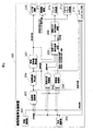
- FIG. 1 is an ECU configuration diagram of a vehicle parking assistance apparatus according to an embodiment of the present invention.
- a camera control unit 107 is connected to a front camera 101, a left camera 102, a rear camera 103, a right camera 104, and a user interface unit 105 through LVDS.
- the camera control unit 107 is connected to the user interface unit 105, the steer control unit 106, the engine control unit 108, and the brake control unit 109 by CAN.
- the front camera 101 is, for example, a camera that images the front of the vehicle.
- the left camera 102 is, for example, a camera that images the left side of the vehicle.
- the rear camera 103 is, for example, a camera that images the rear of the vehicle.
- the right camera 104 captures the right side of the vehicle, for example, a camera.
- the user interface unit 105 combines the parking position and parking locus calculated by the camera control unit 106 with the images captured by the front camera 101, the left camera 102, the rear camera 103, and the right camera 104, and presents them to the driver.
- a vehicle-mounted display with a touch panel receives a parking assistance start instruction from the driver.
- the user interface unit 105 receives the image synthesized by the camera control unit 106 via LVDS, displays the main image, and notifies the camera control unit 106 of a parking support start instruction from the driver via CAN.
- the camera control unit 106 includes a parking frame recognition unit, a parking frame locus calculation unit, a road surface shape recognition unit, an obstacle recognition unit, a steering angle command value calculation unit, a steering / torque command value calculation unit, a steering / torque command value addition unit, And an idling stop determination unit.
- the camera control unit 106 calculates the steering angle command value, calculates the speed command value or / and the engine torque amount command value to the steering control unit, and the engine control unit, and Send to the brake control unit via CAN.
- the steering control unit 107 performs steering control using the steering angle command value calculated by the camera control unit 106, and performs automatic steering during parking assistance.
- the engine control unit 108 performs engine control using the speed command value or / and engine torque amount command value calculated by the camera control unit 106, and performs vehicle speed control during parking assistance.
- the brake control unit 109 performs brake control using the speed command value or / and the engine torque amount command value calculated from the camera control unit 106, and performs brake control during parking assistance.
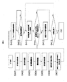
- the vehicle parking assistance apparatus 200 includes a front-rear imaging unit 201, a left-right imaging unit 202, a parking frame recognition unit 203, a parking locus calculation unit 204, a road surface shape recognition unit 205, an obstacle recognition unit 206, and a steering angle command value.
- a calculation unit 207, a speed / torque command value calculation unit 208, a speed / torque command value addition unit 209, a steering control unit 210, a vehicle speed control unit 211, a brake control unit 212, an idling stop control unit 213, and a user interface unit 214 are provided.
- a feature of the present invention is a vehicle parking assistance apparatus including a speed / torque command value calculation unit 208, a speed / torque command value addition unit 209, a road surface shape recognition unit 205, and an obstacle recognition unit 206.
- the front and rear imaging unit 201 is a front camera 101 and a rear camera 103 that image the front and rear of the vehicle.
- the left and right imaging unit 202 is a left camera 102 and a right camera 104 that image the left and right sides of the vehicle.
- the parking frame recognition unit 203 is a block in the camera control unit 106, and recognizes the parking frame position by analyzing the front and rear imaging units 201 and the left and right imaging units 202.
- the parking locus calculation unit 204 is a block in the camera control unit 106, and calculates a parking locus to the parking position based on the distance and direction from the current vehicle stop position to the parking position recognized by the parking frame recognition unit 203. .
- Fig. 3 shows the calculated parking locus.
- the parking locus is calculated from a parking support start position 300 to a switching position 301 and a parking support end position 302.
- the road surface shape recognition unit 205 is a block in the camera control unit 106 and detects the gradient of the road surface condition in the parking lot.
- the gradient of the road surface condition may be detected using an acceleration sensor, or the gradient of the road surface condition may be detected by image analysis of captured images by the front and rear imaging unit 201 and the left and right imaging unit 202.
- the obstacle recognition unit 206 is a block in the camera control unit 106, and detects whether there is an obstacle and a step in the parking locus calculated by the parking locus calculation unit 204.
- the height and distance of the obstacle and the step are calculated by image analysis of the captured image by the front and rear imaging unit 201 and the left and right imaging unit 202.
- the height of a car stop such as in coin parking is regulated, if a car parking stop is detected, or if it is known from the map data that it is coin parking, a fault that is held in advance Object height data may be used.
- the steering angle command value calculation unit 207 is a block in the camera control unit 106, and calculates the steering angle command value in advance based on the parking locus calculated by the parking locus calculation unit 204.
- the speed / torque command value calculation unit 208 is a block in the camera control unit 106.
- the obstacle detected by the obstacle recognition unit 206 the presence or absence of a step, the obstacle, the height and distance of the step, and road surface shape recognition.
- the steering angle command value calculated by the steering angle command value calculation unit 207 Based on the gradient of the road surface condition in the parking lot detected by the unit 205, the steering angle command value calculated by the steering angle command value calculation unit 207, and the parking locus calculated by the parking locus calculation unit 204, acceleration / deceleration of the vehicle in advance.
- the speed command value or / and the engine torque amount command value that predicts the above is calculated in advance before the start of parking assistance.
- the speed command value to be calculated and / or the engine torque amount command value is set higher than when the obstacle is not detected.
- the speed command value and / or the engine torque amount command value are set based on the slope of the road surface shape. For example, when the road surface shape of the parking lot is uphill, the speed command value or / and the engine torque amount command value are set high, and when the road surface shape of the parking lot is downhill, the speed command value or / and When the idling stop determination unit 213 determines that the engine torque amount command value is set low or the engine can be moved to the target position even when the engine is stopped, parking is performed in the idling stop state.
- the speed / torque command value adding unit 209 is a block in the camera control unit 106 and adds the speed command value or / and the engine torque amount command value calculated by the speed / torque command value calculating unit 208.
- the steer control unit 210 is a block in the steer control unit 107, performs steer control using the steering angle calculated in advance by the steering angle command value calculation unit 207, and performs automatic steering according to the parking locus.
- the vehicle speed control unit 211 is a block in the engine control unit 108, performs vehicle speed control based on the speed command value or / and the engine torque amount command value calculated in advance by the speed / torque amount command value adding unit 209, and the parking locus. Car speed control according to
- the brake control unit 212 is a block in the brake control unit 109, performs brake control based on the speed command value or / and the engine torque amount command value calculated in advance by the speed / torque amount command value adding unit 209, and the parking locus. Brake control according to
- the idling stop determination unit 213 is a block in the camera control unit 106, and whether or not idling can be stopped based on the speed command value or / and the engine torque amount command value calculated in advance by the speed / torque amount command value adding unit 209. Make a decision.
- the user interface unit 214 combines the parking position recognized by the parking frame recognition unit 203 and the parking locus calculated by the parking locus calculation unit 204 with the image captured by the front and rear imaging unit 201 and the left and right imaging unit 202 to the driver.
- it is a vehicle-mounted display with a touch panel that receives and receives a parking assistance start instruction from the driver.
- the front and rear imaging unit 201 and the left and right imaging unit 202 image the front-rear and the left and right sides of the vehicle (step S401).
- the parking frame recognizing unit 203 recognizes the parking frame by analyzing the front-rear and left-right images captured by the front-rear imaging unit 201 and the left-right imaging unit 202 (step S402).
- the parking locus calculation unit 204 calculates the parking locus to the parking position based on the distance and direction from the current vehicle stop position to the parking position recognized by the parking position recognition unit 203 (step S403).
- the obstacle recognizing unit 206 calculates whether there are obstacles and steps in the parking locus calculated by the parking locus calculating unit 204, and if so, calculates the heights and distances of the obstacles and steps. (Step S404).
- the road surface shape recognition unit 205 detects the gradient of the road surface condition in the parking lot (step S405).
- the rudder angle command value calculation unit 207 calculates a rudder angle command value in advance based on the parking locus calculated by the parking locus calculation unit 204 (step S406).
- the speed / torque command value calculation unit 208 detects the obstacle detected by the obstacle recognition unit 206, the presence or absence of a step, the obstacle, the height and distance of the step, and the parking surface detected by the road surface shape recognition unit 205. Based on the slope of the road surface condition in the field, the rudder angle command value calculated by the rudder angle command value calculation unit 207, and the parking locus calculated by the parking locus calculation unit 204, The speed command value calculated by the speed / torque command value calculating unit 208 by the speed / torque command value adding unit 209 and / or the engine torque amount after calculating the engine torque amount command value in advance before starting parking assistance. The command value is added (step S407).
- the user interface unit 214 combines the parking position recognized by the parking frame recognition unit 203 and the parking locus calculated by the parking locus calculation unit 204 with the images captured by the front and rear imaging unit 201 and the left and right imaging unit 202. To the driver (step S408).
- the user interface unit 214 instructs the vehicle parking support apparatus to start steering control and vehicle speed control (step S409).
- the steer control unit 210, the vehicle speed control unit 211, and the brake control unit 212 perform the steer control using the steering angle calculated in advance by the steering angle command value calculation unit 107, and the speed / torque amount command value calculation unit 108. Based on the speed command value or / and the engine torque amount command value calculated in advance, the vehicle speed control and the brake control are performed (step S410).
- the vehicle speed control unit 211 notifies the user interface unit 214 that the vehicle has stopped when there is a level difference that cannot be overcome and the vehicle stops during parking assistance, and the user interface unit 214 Displays this to the driver. Then, the user interface unit 214 waits for a parking assistance start instruction from the driver, and confirms the intention of the driver whether to get over the step or the like (step S411).
- the vehicle speed control unit 211 increases the speed command value or / and the engine torque amount (step S412).
- the host vehicle moves to the target position and stops the vehicle (step S413).
- the vehicle switches from the parking support start position 300 to advance to the position 301, moves backward to the parking support end position 302, and then ends the parking support.
- the steps S401 to S409 are sequentially executed and switched to set the target position at the position 301, and then the parking support is started.
- the steps S410 to S412 are repeatedly executed and switched to advance the vehicle to the position 301.
- steps S401 to S408 are sequentially executed, and after setting the target position at the parking support end position 302, the steps S410 to S412 are repeatedly executed to move the vehicle backward to the parking support end position 302 and to provide parking support. Exit.
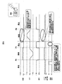
- P0 is a parking assistance start position
- P1 is a switching position
- P2 is a parking assistance end position.
- this timing chart it is assumed that there is a step between P1 and P2.
- the parking frame is recognized and the parking locus is calculated. Then, the speed command value or / and the engine torque amount command value are calculated in advance based on the parking locus, the road surface shape, the obstacle, the height of the step, and the distance. However, in this case, since there is a step, the vehicle speed control is performed by setting the speed command value and / or the engine torque amount command value higher than when there is no step. Further, since the speed command value or / and the engine torque amount command value are set high, the vehicle speed during parking assistance increases accordingly.
- a torque amount command value is calculated.
- the vehicle speed control value is controlled based on the calculated speed command value or / and the engine torque amount command value, and a vehicle parking support device is provided that does not decrease in speed, exceed the speed, or stop the vehicle during parking support. be able to.
- FIG. 6 is a block diagram showing the overall configuration of the vehicle parking assistance apparatus 200 according to the embodiment of the present invention.
- the configuration different from the first embodiment is that a lean fuel control unit 614 is further provided.
- the description of the same contents as in the first embodiment is omitted.
- Lean fuel 614 controls the implementation of lean fuel.
- the vehicle speed of the vehicle is controlled while braking by the brake control unit 612 so that the vehicle speed of the vehicle becomes a constant vehicle speed.
- the brake control unit 612 uses the obstacle detected by the obstacle recognition unit 605 and the distance to the step and the distance the vehicle has moved during parking assistance so that the vehicle speed is constant even after the obstacle and the step are overcome.
- the brake is controlled by
- the speed command value or / and the engine torque amount command value obtained by adding a certain amount is used, resulting in poor fuel consumption. Therefore, it is preferable to use lean fuel by the lean fuel portion 614 during parking assistance. As described above, with the above-described configuration, it is possible to provide a vehicle parking assistance device that keeps the vehicle speed constant and does not collide with other parked vehicles even immediately after overcoming obstacles and steps.
- the speed command value or / and the engine torque amount command value obtained by adding a certain amount is used, so that the fuel consumption is deteriorated.
Landscapes
- Engineering & Computer Science (AREA)
- Mechanical Engineering (AREA)
- Transportation (AREA)
- Chemical & Material Sciences (AREA)
- Combustion & Propulsion (AREA)
- Automation & Control Theory (AREA)
- Human Computer Interaction (AREA)
- Radar, Positioning & Navigation (AREA)
- Remote Sensing (AREA)
- Computer Networks & Wireless Communication (AREA)
- Physics & Mathematics (AREA)
- General Physics & Mathematics (AREA)
- Control Of Driving Devices And Active Controlling Of Vehicle (AREA)
- Steering Control In Accordance With Driving Conditions (AREA)
- Control Of Vehicle Engines Or Engines For Specific Uses (AREA)
Abstract
駐車支援中に速度低下、速度超過、及び車両停止することなく駐車することができる、並びに障害物、及び段差の乗り越えた直後にも車両の自車速度を一定とし、他の駐車車両等に衝突しない車両用駐車支援装置を提供すること。 駐車軌跡内の障害物、及び段差の高さと距離、路面状況の勾配、及び操舵角に応じて予め車両の加減速度を予測した速度指令値又は/及びエンジントルク量指令値を算出し、前記算出した速度指令値又は/及びエンジントルク量指令値に基づき車両の速度制御を行う。
Description
本発明は、車両用駐車支援装置に関する。
ドライバによるステア操作、アクセル操作、及びブレーキ操作無しに駐車位置まで自動で車両を移動することができる駐車支援装置が現在いろいろなメーカにて開発されている。その駐車支援装置では、駐車位置までの最適軌跡を算出し、最適軌跡を維持するための操舵角を算出し、操舵角による減速あるいは勾配や段差による減速があっても車速を維持するように駐車支援を行う車両用駐車支援装置が知られている(例えば、特許文献1参照)。
しかしながら、特許文献1に開示されている技術では、操舵角、障害物、及び勾配の減速を駐車支援中の車両の自車速度を計測し、車速度が所定速度以下ならば駆動力を算出、補正し駐車支援を行っている。
この場合、前記所定速度と計測された自車速度との差、あるいは自車速変化率から駆動力を算出し、駆動力の変化に依存して前記自車速度との差が小さくなる、あるいは自車速度の変化率が少なくなることにより自車速度を制御し、前記所定速度を保つことができる。
しかし、駐車軌跡中に障害物があり自車両が停止した場合には、駆動力を変化させたとしても自車速度が変化せず0のままとなるため、車両の自車速度を維持する事ができない。自車速が分からない場合でも、非常にゆっくり駆動力を上げて乗り越える事はできるが、目標位置に駐車するまで時間がかかるか、駐車を完了させることができない。
また、障害物を乗り越えるために強めの駆動力を印加した場合には、勢いよく障害物を乗り越えてしまう可能性があり、他の駐車車両等に衝突する恐れがある。
上記課題を解決するために、例えば、本発明の車両用駐車支援装置は、駐車軌跡内の障害物、及び段差の高さと距離、路面状況の勾配、及び操舵角に応じて予め車両の加減速度を予測した速度指令値又は/及びエンジントルク量指令値を算出し、前記算出した速度指令値又は/及びエンジントルク量指令値に基づき車両の速度制御を行う。
本発明によれば、駐車支援中に速度低下、速度超過、及び車両停止することなく駐車することができる、並びに障害物、及び段差の乗り越えた直後にも車両の自車速度を一定とし、他の駐車車両等に衝突しない車両用駐車支援装置を提供することができる。
以下、図面を用いて本発明の実施例について詳述する。
本発明の第1の実施の形態に係る車両用駐車支援装置について図面に従って説明する。
図1は、本発明の実施の形態に係る車両用駐車支援装置のECU構成図である。図1において、カメラコントロールユニット107は、前カメラ101、左カメラ102、後カメラ103、右カメラ104、及びユーザインターフェースユニット105とLVDSにて接続している。また、カメラコントロールユニット107は、ユーザインターフェースユニット105、ステアコントロールユニット106、エンジンコントロールユニット108、ブレーキコントロールユニット109とCANにて接続している。
前カメラ101は車両の前方を撮像する、例えばカメラである。左カメラ102は車両の左方を撮像する、例えばカメラである。後カメラ103は車両の後方を撮像する、例えばカメラである。右カメラ104は車両の右方を撮像する、例えばカメラである。
ユーザインターフェースユニット105は、前カメラ101、左カメラ102、後カメラ103、及び右カメラ104が撮像した画像に、カメラコントロールユニット106が算出した駐車位置と駐車軌跡とを合成してドライバに提示する、並びにドライバからの駐車支援開始指示を受けとる、例えばタッチパネル付き車載用ディスプレイである。
なお、ユーザインターフェースユニット105は、カメラコントロールユニット106が合成した画像をLVDS経由で受け本画像の表示を行い、ドライバからの駐車支援開始指示はCAN経由でカメラコントロールユニット106に通知する。
カメラコントロールユニット106は、駐車枠認識部、駐車枠軌跡算出部、路面形状認識部、障害物認識部、舵角指令値算出部、操舵/トルク指令値算出部、操舵/トルク指令値加算部、及びアイドリングストップ判断部とを備えたカメラコントロールユニットである。
なお、車両用駐車支援装置を制御するために、カメラコントロールユニット106は、舵角指令値を算出しステアコントロールユニットへ、速度指令値又は/及びエンジントルク量指令値を算出しエンジンコントロールユニット、及びブレーキコントロールユニットへCAN経由で送信する。
ステアコントロールユニット107は、カメラコントロールユニット106より算出した舵角指令値を用いてステア制御を行い、駐車支援中の自動操舵を行う。
エンジンコントロールユニット108は、カメラコントロールユニット106より算出した速度指令値又は/及びエンジントルク量指令値を用いてエンジン制御を行い、駐車支援中の車速制御を行う。
ブレーキコントロールユニット109は、カメラコントロールユニット106より算出した速度指令値又は/及びエンジントルク量指令値を用いてブレーキ制御を行い、駐車支援中のブレーキ制御を行う。
以下、本発明の第1の実施の形態に係る車両用駐車支援装置200の動作について図2のブロック図に従って説明する。図2において、車両用駐車支援装置200は、前後撮像部201、左右撮像部202、駐車枠認識部203、駐車軌跡算出部204、路面形状認識部205、障害物認識部206、舵角指令値算出部207、速度/トルク指令値算出部208、速度/トルク指令値加算部209、ステア制御部210、車速制御部211、ブレーキ制御部212、アイドリングストップ制御部213、及びユーザインターフェース部214を備える。本発明の特徴は速度/トルク指令値算出部208、速度/トルク指令値加算部209、路面形状認識部205、及び障害物認識部206を含む車両用駐車支援装置である。
前後撮像部201は車両の前後方を撮像する、前カメラ101、後カメラ103である。左右撮像部202は車両の左右方を撮像する、左カメラ102、右カメラ104である。
駐車枠認識部203は、カメラコントロールユニット106内のブロックであり、前後撮像部201、及び左右撮像部202が撮像した前後左右の画像を解析することによって駐車枠位置を認識する。
駐車軌跡算出部204は、カメラコントロールユニット106内のブロックであり、現在の車両停止位置から駐車枠認識部203が認識した駐車位置までの距離と方向に基づき、駐車位置までの駐車軌跡を算出する。
算出する駐車軌跡を図3に示す。駐車軌跡は、駐車支援開始位置である300から、切換えし位置がある301、駐車支援終了位置までの302を算出する。
路面形状認識部205は、カメラコントロールユニット106内のブロックであり、駐車場内の路面状況の勾配を検知する。これは加速度センサーを用いて路面状況の勾配を検知しても良いし、前後撮像部201、及び左右撮像部202による撮像画像の画像解析によって路面状況の勾配を検知しても良い。
障害物認識部206は、カメラコントロールユニット106内のブロックであり、駐車軌跡算出部204が算出した駐車軌跡内に障害物、及び段差が有るか無いかを検知する。障害物、及び段差を検知した場合には、前後撮像部201、及び左右撮像部202による撮像画像の画像解析によって、障害物、及び段差の高さと距離を算出する。また、コインパーキングにあるような車止めは高さが規定されているため、コインパーキングの車止め検知した場合、または、地図データからコインパーキングであることが分かっている場合は、予め保持している障害物の高さデータを用いても良い。
舵角指令値算出部207は、カメラコントロールユニット106内のブロックであり、駐車軌跡算出部204が算出した駐車軌跡に基づき舵角指令値を事前に算出する。
速度/トルク指令値算出部208は、カメラコントロールユニット106内のブロックであり、障害物認識部206にて検出した障害物、及び段差の有無と障害物、及び段差の高さと距離、路面形状認識部205にて検出した駐車場内の路面状況の勾配、舵角指令値算出部207にて算出した舵角指令値、並びに駐車軌跡算出部204が算出した駐車軌跡に基づいて、予め車両の加減速を予測した速度指令値又は/及びエンジントルク量指令値を駐車支援開始前に事前に算出する。
障害物が検知された場合は、障害物が検知されなかった場合に比べて、算出する速度指令値又は/及びエンジントルク量指令値を高く設定する。
また、路面形状の傾きに基づいて、速度指令値又は/及びエンジントルク量指令値を設定する。例えば、駐車場の路面形状が上り坂の場合には、速度指令値又は/及びエンジントルク量指令値を高く設定し、駐車場の路面形状が下り道だった場合は、速度指令値又は/及びエンジントルク量指令値を低く設定する、若しくはエンジン停止状態でも目標位置に移動出来るとアイドリングストップ判断部213により判断した場合には、アイドリングストップ状態で駐車を行う。
なお、車両の重量をm[kg]、障害物の高さh[m]、重力加速度g[m/s2]、及び時間をt[s]とすると、算出する速度指令値v[m/s]、及びエンジントルク量指令値F[N]は以下計算式より算出される。
v[m/s] = (2 * g * h)1/2 ・・・・・・・・・・・ (式1.1)
F[N] = m * (2 * g * h)1/2 / Δt ・・・・・・・(式1.2)
速度/トルク指令値加算部209は、カメラコントロールユニット106内のブロックであり、速度/トルク指令値算出部208にて算出した速度指令値又は/及びエンジントルク量指令値を加算する。
F[N] = m * (2 * g * h)1/2 / Δt ・・・・・・・(式1.2)
速度/トルク指令値加算部209は、カメラコントロールユニット106内のブロックであり、速度/トルク指令値算出部208にて算出した速度指令値又は/及びエンジントルク量指令値を加算する。
ステア制御部210は、ステアコントロールユニット107内のブロックであり、舵角指令値算出部207により事前に算出した舵角を用いてステア制御を行い、駐車軌跡に応じた自動操舵を行う。
車速制御部211は、エンジンコントロールユニット108内のブロックであり、速度/トルク量指令値加算部209より事前に算出した速度指令値又は/及びエンジントルク量指令値に基づき車速制御を行い、駐車軌跡に応じた自動車速制御を行う。
ブレーキ制御部212は、ブレーキコントロールユニット109内のブロックであり、速度/トルク量指令値加算部209より事前に算出した速度指令値又は/及びエンジントルク量指令値に基づきブレーキ制御を行い、駐車軌跡に応じたブレーキ制御を行う。
アイドリングストップ判断部213は、カメラコントロールユニット106内のブロックであり、速度/トルク量指令値加算部209より事前に算出した速度指令値又は/及びエンジントルク量指令値に基づきアイドリングストップ可能か否かの判断を行う。
ユーザインターフェース部214は、前後撮像部201、及び左右撮像部202が撮像した画像に、駐車枠認識部203が認識した駐車位置と駐車軌跡算出部204が算出した駐車軌跡とを合成してドライバに提示する、並びにドライバからの駐車支援開始指示を受けとる、例えばタッチパネル付き車載用ディスプレイである。
以下、本発明の第1の実施の形態に係る車両用駐車支援装置200の動作について図4のフロー図に従って説明する。
まず、ドライバが駐車支援を開始するために、駐車支援装置200を起動すると、前後撮像部201、及び左右撮像部202にて、車両の前後方、及び左右方を撮像する(ステップS401)。
次に、駐車枠認識部203は、前後撮像部201、及び左右撮像部202が撮像した前後左右の画像を解析することによって駐車枠を認識する(ステップS402)。
次に、駐車軌跡算出部204は、現在の車両停止位置から駐車位置認識部203が認識した駐車位置までの距離と方向に基づき、駐車位置までの駐車軌跡を算出する(ステップS403)。
次に、障害物認識部206は、駐車軌跡算出部204が算出した駐車軌跡内に障害物、及び段差が有るか無いか、有る場合は障害物、及び段差の高さと距離を算出する。(ステップS404)。
次に、路面形状認識部205は、駐車場内の路面状況の勾配を検知する(ステップS405)。
次に、舵角指令値算出部207は、駐車軌跡算出部204が算出した駐車軌跡に基づき舵角指令値を事前に算出する(ステップS406)。
次に、速度/トルク指令値算出部208は、障害物認識部206にて検出した障害物、及び段差の有無と障害物、及び段差の高さと距離、路面形状認識部205にて検出した駐車場内の路面状況の勾配、舵角指令値算出部207にて算出した舵角指令値、並びに駐車軌跡算出部204が算出した駐車軌跡に基づいて、予め車両の加減速を予測した速度指令値又は/及びエンジントルク量指令値を駐車支援開始前に事前に算出した後、速度/トルク指令値加算部209にて速度/トルク指令値算出部208にて算出した速度指令値又は/及びエンジントルク量指令値を加算する(ステップS407)。
次に、ユーザインターフェース部214は、前後撮像部201、及び左右撮像部202が撮像した画像に、駐車枠認識部203が認識した駐車位置と駐車軌跡算出部204が算出した駐車軌跡とを合成してドライバに提示する(ステップS408)。
次に、ユーザインターフェース部214は、ドライバから駐車支援開始指示を受けると車両用駐車支援装置に操舵制御、車速制御を開始するよう指示を行う(ステップS409)。
次に、ステア制御部210、車速制御部211、及びブレーキ制御部212は、舵角指令値算出部107により事前に算出した舵角を用いたステア制御、並びに速度/トルク量指令値算出部108により事前に算出した速度指令値又は/及びエンジントルク量指令値に基づき車速制御、及びブレーキ制御を行う(ステップS410)。
次に、車速制御部211は、乗り越えられない段差等があり、駐車支援中に車両が停止してしまった場合には、ユーザインターフェース部214に車両が停止したことを通知し、ユーザインターフェース部214はその旨をドライバへ表示する。そして、ユーザインターフェース部214はドライバからの駐車支援開始指示を待ち、ドライバに段差等を乗り越えるか否かの意図を確認する(ステップS411)。
次に、車速制御部211には、ユーザインターフェース部214から駐車支援開始指示を受けると、速度指令値又は/及びエンジントルク量を増加させる(ステップS412)。
次に、目標位置に自車両が移動し、車両を停止させる(ステップS413)。
以下、本発明の第1の実施の形態に係る駐車の様子を図3の模式図に従って説明する。
車両は駐車支援開始位置300から、切換えし位置301まで前進し、駐車支援終了位置302まで後進した後、駐車支援を終了する。
駐車支援開始位置300ではS401~S409までを順次実行し、切換えし位置301に目標位置を設定した後に駐車支援を開始し、S410~S412を繰り返し実行し切換えし位置301まで車両を前進する。次に、切換えし位置301ではS401~S408までを順次実行し、駐車支援終了位置302に目標位置を設定した後に、S410~S412を繰り返し実行し駐車支援終了位置302まで車両を後進し、駐車支援を終了する。
以下、本発明の第1の実施の形態に係る段差がある場合のタイミングチャートを図5に従って説明する。P0は駐車支援開始位置、P1は切換えし位置、及びP2は駐車支援終了位置である。また、本タイミングチャートではP1からP2までの間に段差が有ると仮定している。
車両が停止しているP1の時点で、駐車枠を認識して、駐車軌跡を算出する。そして、駐車軌跡と路面形状、障害物、及び段差の高さ、距離に基づいて速度指令値又は/及びエンジントルク量指令値を事前に算出する。但し、本ケースの場合は、段差が有るため、段差が無い場合に比べて速度指令値又は/及びエンジントルク量指令値を高く設定し、車速制御を行う。また、速度指令値又は/及びエンジントルク量指令値を高く設定しているため、それに伴い駐車支援中の車速度も高くなる。
以上説明したように、上記構成により、駐車軌跡内の障害物、及び段差の高さと距離、路面状況の勾配、並びに操舵角に応じて予め車両の加減速度を予測した速度指令値又は/及びエンジントルク量指令値を算出する。そして、その算出した速度指令値又は/及びエンジントルク量指令値に基づき車両の速度制御を行い、駐車支援中に速度低下、速度超過、及び車両停止することがない車両用駐車支援装置を提供することができる。
以下、本発明の第2の実施の形態に係る車両用駐車支援装置について図面に従って説明する。
図6は、本発明の実施の形態に係る車両用駐車支援装置200の全体構成を示すブロック図である。第1の実施の形態と異なる構成は、希薄燃料制御部614を更に備える点である。第1の実施の形態と同一の内容については説明を省略する。
希薄燃料614は、希薄燃料(リーンバーン)の実施を制御する。
実施例2での駐車支援は、速度/トルク指令値算出部608で算出した速度指令値又は/及びエンジントルク量指令値に、障害物、及び段差を乗り越えるためにある一定量を加算した速度指令値又は/及びエンジントルク量指令値を用い、車両の自車速度が一定車速になるよう、ブレーキ制御部612によりブレーキをかけながら、車両の自車速度を制御する。そして、障害物認識部605により検知した障害物、及び段差までの距離と駐車支援中に車両が移動した距離を用い、障害物、段差を乗り越えた直後にも一定車速となるようブレーキ制御部612によりブレーキ制御を行う。
また、駐車支援中は一定量を加算した速度指令値又は/及びエンジントルク量指令値を用いるため燃費が悪くなる。そのため、駐車支援中は希薄燃料部614により希薄燃料(リーンバーン)を用いることが好ましい。
以上説明したように上記構成により、障害物、段差の乗り越えた直後も、車両の自車速度を一定とし、他の駐車車両等に衝突しない車両用駐車支援装置を提供することができる。
以上説明したように上記構成により、障害物、段差の乗り越えた直後も、車両の自車速度を一定とし、他の駐車車両等に衝突しない車両用駐車支援装置を提供することができる。
また、駐車支援中は一定量を加算した速度指令値又は/及びエンジントルク量指令値を用いるため燃費が悪くなるところ、駐車支援中は希薄燃料を用いることで燃費を維持することが可能となる。
101 前カメラ
102 左カメラ
103 右カメラ
104 後カメラ
105 ユーザインターフェースユニット
106 カメラコントロールユニット
107 ステアコントロールユニット
108 エンジンコントロールユニット
109 ブレーキコントロールユニット
200 車両用駐車支援装置
201 前後撮像部
202 左右撮像部
203 駐車枠認識部
204 駐車軌跡算出部
205 路面形状認識部
206 障害物認識部
207 舵角指令値算出部
208 速度/トルク指令値算出部
209 速度/トルク指令値加算部
210 ステア制御部
211 車速制御部
212 ブレーキ制御部
213 アイドリングストップ判断部
214 ユーザインターフェース部
600 車両用駐車支援装置
601 前後撮像部
602 左右撮像部
603 駐車枠認識部
604 駐車軌跡算出部
605 路面形状認識部
606 障害物認識部
607 舵角指令値算出部
608 速度/トルク指令値算出部
609 速度/トルク指令値加算部
610 ステア制御部
611 車速制御部
612 ブレーキ制御部
613 アイドリングストップ判断部
614 ユーザインターフェース部
615 希薄燃料部
Claims (7)
- 速度/トルク指令値算出部と、
速度/トルク指令値加算部と、
障害物認識部と、
路面形状認識部と、を有することを特徴とする車両用駐車支援装置。 - 駐車軌跡内の障害物、及び段差の高さと距離、路面状況の勾配、及び操舵角に応じて予め車両の加減速度を予測した速度指令値又は/及びエンジントルク量指令値を算出し、
前記算出した速度指令値又は/及びエンジントルク量指令値に基づき車両の速度制御を行う車両用駐車支援装置。 - 請求項2に記載の車両用駐車支援装置において、
障害物認識部で障害物が検知された場合、障害物が検知されなかった場合に比べて、算出する速度指令値又は/及びエンジントルク量指令値を高く設定する車両用駐車支援装置。 - 請求項2に記載の車両用駐車支援装置において、
舵角及び駐車場内の路面形状の勾配に応じて算出する速度指令値/及びエンジントルク量指令値を高く、若しくは、低く設定する車両用駐車支援装置。 - 請求項2に記載の車両用駐車支援装置において、
障害物、段差を乗り越えるために一定量を加算した速度指令値又は/及びエンジントルク量指令値を出力し、一定車速になるようにブレーキをかけつつ、障害物、及び段差の乗り越えた直後にも、車両の自車速度を一定とすることができる車両用駐車支援装置。 - 請求項2に記載の車両用駐車支援装置において、
エンジン停止状態でも目標位置に移動出来ると判断した場合にはアイドリングストップ状態で駐車枠まで移動するように制御する車両用駐車支援装置。 - 請求項2に記載の車両用駐車支援装置において、
駐車支援中に障害物にあたり車両が停止した場合、ドライバに乗り越えるか否かの意図をきく手段を有する車両用駐車支援装置。
Priority Applications (4)
| Application Number | Priority Date | Filing Date | Title |
|---|---|---|---|
| US15/577,383 US11059477B2 (en) | 2015-07-31 | 2016-07-11 | Parking assist device for vehicle |
| EP16832692.4A EP3330146B1 (en) | 2015-07-31 | 2016-07-11 | Parking assist device for vehicle |
| JP2017532447A JP6483264B2 (ja) | 2015-07-31 | 2016-07-11 | 車両用駐車支援装置 |
| CN201680028394.9A CN107614345B (zh) | 2015-07-31 | 2016-07-11 | 车辆用泊车辅助装置 |
Applications Claiming Priority (2)
| Application Number | Priority Date | Filing Date | Title |
|---|---|---|---|
| JP2015151454 | 2015-07-31 | ||
| JP2015-151454 | 2015-07-31 |
Publications (1)
| Publication Number | Publication Date |
|---|---|
| WO2017022413A1 true WO2017022413A1 (ja) | 2017-02-09 |
Family
ID=57942835
Family Applications (1)
| Application Number | Title | Priority Date | Filing Date |
|---|---|---|---|
| PCT/JP2016/070361 Ceased WO2017022413A1 (ja) | 2015-07-31 | 2016-07-11 | 車両用駐車支援装置 |
Country Status (5)
| Country | Link |
|---|---|
| US (1) | US11059477B2 (ja) |
| EP (1) | EP3330146B1 (ja) |
| JP (1) | JP6483264B2 (ja) |
| CN (1) | CN107614345B (ja) |
| WO (1) | WO2017022413A1 (ja) |
Cited By (6)
| Publication number | Priority date | Publication date | Assignee | Title |
|---|---|---|---|---|
| JP2019046100A (ja) * | 2017-08-31 | 2019-03-22 | アイシン精機株式会社 | 駐車支援装置 |
| GB2568881A (en) * | 2017-11-28 | 2019-06-05 | Jaguar Land Rover Ltd | Vehicle control apparatus and method |
| CN110267867A (zh) * | 2017-03-08 | 2019-09-20 | 雷诺股份公司 | 机动车辆驻车辅助方法和系统 |
| JP2020075536A (ja) * | 2018-11-05 | 2020-05-21 | 株式会社Soken | 駆動力制御装置 |
| JP2020131787A (ja) * | 2019-02-14 | 2020-08-31 | アイシン精機株式会社 | 管制装置及び車両制御装置 |
| JP2022134209A (ja) * | 2021-03-03 | 2022-09-15 | 株式会社Subaru | 車両制御装置 |
Families Citing this family (12)
| Publication number | Priority date | Publication date | Assignee | Title |
|---|---|---|---|---|
| JP6545108B2 (ja) * | 2016-01-14 | 2019-07-17 | アルパイン株式会社 | 駐車支援装置および駐車支援方法 |
| KR102327344B1 (ko) * | 2017-05-23 | 2021-11-17 | 주식회사 만도모빌리티솔루션즈 | 스마트 주차 보조 시스템 및 그 제어 방법 |
| JP7116427B2 (ja) * | 2018-05-10 | 2022-08-10 | 本田技研工業株式会社 | 駐車支援装置及び自動駐車可能な車両 |
| US11511733B2 (en) | 2019-11-20 | 2022-11-29 | Ford Global Technologies, Llc | Vehicle parking system |
| JP6956165B2 (ja) * | 2019-12-13 | 2021-10-27 | 本田技研工業株式会社 | 駐車支援装置及び自動駐車可能な車両 |
| JP7347307B2 (ja) * | 2020-04-02 | 2023-09-20 | 株式会社デンソー | 駐車支援装置、駐車支援システム、及び駐車支援方法 |
| CN111731274B (zh) * | 2020-06-28 | 2021-11-02 | 中国第一汽车股份有限公司 | 泊车扭矩的确定方法、装置、设备和介质 |
| CN112124302B (zh) * | 2020-08-18 | 2022-02-22 | 上海元城汽车技术有限公司 | 自动泊车控制方法、装置、车辆及存储介质 |
| CN112462781A (zh) * | 2020-11-30 | 2021-03-09 | 广州小鹏自动驾驶科技有限公司 | 一种越障方法和装置 |
| CN112455429B (zh) * | 2020-11-30 | 2022-05-13 | 广州小鹏自动驾驶科技有限公司 | 一种泊车控制方法、装置、车辆和可读存储介质 |
| CN115946680B (zh) * | 2022-10-29 | 2025-09-23 | 重庆长安汽车股份有限公司 | 低矮障碍识别方法及自动泊车方法、电子设备、存储介质 |
| CN120476064A (zh) * | 2023-02-17 | 2025-08-12 | 深圳引望智能技术有限公司 | 一种智能泊车方法和装置 |
Citations (4)
| Publication number | Priority date | Publication date | Assignee | Title |
|---|---|---|---|---|
| JP2008201270A (ja) * | 2007-02-20 | 2008-09-04 | Toyota Motor Corp | 車両走行支援装置 |
| JP2010230139A (ja) * | 2009-03-30 | 2010-10-14 | Hitachi Automotive Systems Ltd | 自動車の制御方法 |
| JP2013049389A (ja) * | 2011-08-31 | 2013-03-14 | Nissan Motor Co Ltd | 車両の制駆動力制御装置及び制駆動力制御方法 |
| JP2013075619A (ja) * | 2011-09-30 | 2013-04-25 | Mazda Motor Corp | 駐車支援装置 |
Family Cites Families (19)
| Publication number | Priority date | Publication date | Assignee | Title |
|---|---|---|---|---|
| JP4109798B2 (ja) * | 1999-06-22 | 2008-07-02 | 本田技研工業株式会社 | 車両の自動操舵装置 |
| DE10295469D2 (de) * | 2001-11-29 | 2004-10-14 | Daimler Chrysler Ag | Vorrichtung zur Bewertung und/oder Beeinflussung einer Fahrzeugbewegungsgrosse und/oder des FAhrzeugbewegungsverhaltens |
| US8135531B2 (en) * | 2002-06-12 | 2012-03-13 | Nmhg Oregon, Llc | Predictive vehicle controller |
| JP2004106677A (ja) * | 2002-09-18 | 2004-04-08 | Calsonic Kansei Corp | 車両の速度制御方法 |
| JP2004352117A (ja) * | 2003-05-29 | 2004-12-16 | Toyota Motor Corp | 車両走行制御装置および駐車支援装置 |
| DE102004001555B4 (de) * | 2004-01-10 | 2018-02-15 | Robert Bosch Gmbh | Verfahren und System für die Spurführung eines Fahrzeugs |
| JP4557817B2 (ja) * | 2005-06-17 | 2010-10-06 | アイシン精機株式会社 | 運転支援装置 |
| JP4618035B2 (ja) * | 2005-07-27 | 2011-01-26 | 株式会社アドヴィックス | 車両走行制御装置 |
| DE102007061234A1 (de) * | 2007-12-19 | 2009-06-25 | Robert Bosch Gmbh | Verfahren und Vorrichtung zum Anpassen der Führung eines Fahrzeuges |
| JP2010076675A (ja) | 2008-09-26 | 2010-04-08 | Toyota Motor Corp | 車両用駐車支援装置、及び車両用駐車支援方法 |
| WO2011014482A1 (en) * | 2009-07-27 | 2011-02-03 | Magna Electronics Inc. | Parking assist system |
| DE102009046158A1 (de) * | 2009-10-29 | 2011-05-05 | Robert Bosch Gmbh | Verfahren zur Erkennung von Objekten mit geringer Höhe |
| DE102009047248A1 (de) * | 2009-11-27 | 2011-06-01 | Robert Bosch Gmbh | Verfahren zur Unterstützung eines Fahrers eines Kraftfahrzeugs |
| EP2340980B1 (en) * | 2009-12-30 | 2012-05-30 | Magneti Marelli S.p.A. | Parking assistant system |
| JP2012144162A (ja) * | 2011-01-12 | 2012-08-02 | Toyota Motor Corp | 走行支援装置 |
| DE102012014809A1 (de) * | 2012-07-26 | 2014-01-30 | Volkswagen Ag | Verfahren und Vorrichtung zum Erkennen einer Bordsteinüberfahrt |
| JP5983248B2 (ja) * | 2012-09-28 | 2016-08-31 | 株式会社デンソー | 駐車支援装置 |
| JP5975172B2 (ja) * | 2013-04-26 | 2016-08-23 | トヨタ自動車株式会社 | 駐車支援装置 |
| JP6067635B2 (ja) * | 2014-09-12 | 2017-01-25 | アイシン精機株式会社 | 駐車支援装置 |
-
2016
- 2016-07-11 JP JP2017532447A patent/JP6483264B2/ja active Active
- 2016-07-11 WO PCT/JP2016/070361 patent/WO2017022413A1/ja not_active Ceased
- 2016-07-11 US US15/577,383 patent/US11059477B2/en active Active
- 2016-07-11 CN CN201680028394.9A patent/CN107614345B/zh active Active
- 2016-07-11 EP EP16832692.4A patent/EP3330146B1/en active Active
Patent Citations (4)
| Publication number | Priority date | Publication date | Assignee | Title |
|---|---|---|---|---|
| JP2008201270A (ja) * | 2007-02-20 | 2008-09-04 | Toyota Motor Corp | 車両走行支援装置 |
| JP2010230139A (ja) * | 2009-03-30 | 2010-10-14 | Hitachi Automotive Systems Ltd | 自動車の制御方法 |
| JP2013049389A (ja) * | 2011-08-31 | 2013-03-14 | Nissan Motor Co Ltd | 車両の制駆動力制御装置及び制駆動力制御方法 |
| JP2013075619A (ja) * | 2011-09-30 | 2013-04-25 | Mazda Motor Corp | 駐車支援装置 |
Non-Patent Citations (1)
| Title |
|---|
| See also references of EP3330146A4 * |
Cited By (11)
| Publication number | Priority date | Publication date | Assignee | Title |
|---|---|---|---|---|
| CN110267867A (zh) * | 2017-03-08 | 2019-09-20 | 雷诺股份公司 | 机动车辆驻车辅助方法和系统 |
| JP2020514174A (ja) * | 2017-03-08 | 2020-05-21 | ルノー エス.ア.エス.Renault S.A.S. | 自動車駐車支援方法及び自動車駐車支援システム |
| JP7353179B2 (ja) | 2017-03-08 | 2023-09-29 | ルノー エス.ア.エス. | 自動車駐車支援方法及び自動車駐車支援システム |
| JP2019046100A (ja) * | 2017-08-31 | 2019-03-22 | アイシン精機株式会社 | 駐車支援装置 |
| GB2568881A (en) * | 2017-11-28 | 2019-06-05 | Jaguar Land Rover Ltd | Vehicle control apparatus and method |
| JP2020075536A (ja) * | 2018-11-05 | 2020-05-21 | 株式会社Soken | 駆動力制御装置 |
| JP7168416B2 (ja) | 2018-11-05 | 2022-11-09 | 株式会社Soken | 駆動力制御装置 |
| JP2020131787A (ja) * | 2019-02-14 | 2020-08-31 | アイシン精機株式会社 | 管制装置及び車両制御装置 |
| JP7251190B2 (ja) | 2019-02-14 | 2023-04-04 | 株式会社アイシン | 車両走行制御システム |
| JP2022134209A (ja) * | 2021-03-03 | 2022-09-15 | 株式会社Subaru | 車両制御装置 |
| JP7730648B2 (ja) | 2021-03-03 | 2025-08-28 | 株式会社Subaru | 車両制御装置 |
Also Published As
| Publication number | Publication date |
|---|---|
| US11059477B2 (en) | 2021-07-13 |
| CN107614345A (zh) | 2018-01-19 |
| EP3330146A1 (en) | 2018-06-06 |
| CN107614345B (zh) | 2020-05-22 |
| EP3330146A4 (en) | 2019-03-13 |
| JP6483264B2 (ja) | 2019-03-13 |
| EP3330146B1 (en) | 2023-06-14 |
| JPWO2017022413A1 (ja) | 2018-04-05 |
| US20180170366A1 (en) | 2018-06-21 |
Similar Documents
| Publication | Publication Date | Title |
|---|---|---|
| JP6483264B2 (ja) | 車両用駐車支援装置 | |
| US10787168B2 (en) | Automated parking device and automated parking method | |
| JP5803807B2 (ja) | 駐車支援装置、駐車支援方法、プログラム及び媒体 | |
| US8285479B2 (en) | Parking assist apparatus | |
| JP4946631B2 (ja) | 発進支援装置、表示装置 | |
| JP2008174102A (ja) | 駐車支援装置 | |
| KR20140085136A (ko) | 주차조향 보조시스템 | |
| CN105416394B (zh) | 车辆的控制装置以及控制方法 | |
| JP2017047765A (ja) | 走行制御装置 | |
| CN112955356B (zh) | 停车辅助装置及停车辅助方法 | |
| JP6901000B2 (ja) | 駐車支援方法及び駐車支援装置 | |
| WO2018066068A1 (ja) | 駐車制御方法及び駐車制御装置 | |
| EP2116439A1 (en) | Vehicle travel support device and method | |
| JP5929093B2 (ja) | 車両用走行支援装置 | |
| JP4277907B2 (ja) | 自動車の走行制御装置 | |
| JP2008222055A (ja) | 運転補助制御装置 | |
| JP2021146767A (ja) | 走行制御装置、車両、走行制御方法及びプログラム | |
| JP7521701B2 (ja) | 車両制御方法及び車両制御装置 | |
| JP2006176069A (ja) | インターチェンジ合流支援装置 | |
| JP2007190977A (ja) | 車両制御装置 | |
| JP6390525B2 (ja) | 運転支援装置 | |
| JP2019167071A (ja) | 車両用制御装置 | |
| CN115195734B (zh) | 行驶控制装置 | |
| KR101731632B1 (ko) | 오디오 비디오 브리징 시스템이 적용된 차량의 카메라 제어 장치 및 방법 | |
| JP2019098753A (ja) | 自動運転装置及び自動運転方法 |
Legal Events
| Date | Code | Title | Description |
|---|---|---|---|
| 121 | Ep: the epo has been informed by wipo that ep was designated in this application |
Ref document number: 16832692 Country of ref document: EP Kind code of ref document: A1 |
|
| WWE | Wipo information: entry into national phase |
Ref document number: 15577383 Country of ref document: US |
|
| ENP | Entry into the national phase |
Ref document number: 2017532447 Country of ref document: JP Kind code of ref document: A |
|
| NENP | Non-entry into the national phase |
Ref country code: DE |