WO2017024653A1 - 电梯自动解救及节能装置以及其控制方法、以及超级电容器模块 - Google Patents
电梯自动解救及节能装置以及其控制方法、以及超级电容器模块 Download PDFInfo
- Publication number
- WO2017024653A1 WO2017024653A1 PCT/CN2015/089365 CN2015089365W WO2017024653A1 WO 2017024653 A1 WO2017024653 A1 WO 2017024653A1 CN 2015089365 W CN2015089365 W CN 2015089365W WO 2017024653 A1 WO2017024653 A1 WO 2017024653A1
- Authority
- WO
- WIPO (PCT)
- Prior art keywords
- power
- elevator
- module
- energy
- supercapacitor
- Prior art date
- Legal status (The legal status is an assumption and is not a legal conclusion. Google has not performed a legal analysis and makes no representation as to the accuracy of the status listed.)
- Ceased
Links
Images




Classifications
-
- B—PERFORMING OPERATIONS; TRANSPORTING
- B66—HOISTING; LIFTING; HAULING
- B66B—ELEVATORS; ESCALATORS OR MOVING WALKWAYS
- B66B5/00—Applications of checking, fault-correcting, or safety devices in elevators
- B66B5/02—Applications of checking, fault-correcting, or safety devices in elevators responsive to abnormal operating conditions
- B66B5/027—Applications of checking, fault-correcting, or safety devices in elevators responsive to abnormal operating conditions to permit passengers to leave an elevator car in case of failure, e.g. moving the car to a reference floor or unlocking the door
-
- B—PERFORMING OPERATIONS; TRANSPORTING
- B66—HOISTING; LIFTING; HAULING
- B66B—ELEVATORS; ESCALATORS OR MOVING WALKWAYS
- B66B1/00—Control systems of elevators in general
- B66B1/24—Control systems with regulation, i.e. with retroactive action, for influencing travelling speed, acceleration, or deceleration
- B66B1/28—Control systems with regulation, i.e. with retroactive action, for influencing travelling speed, acceleration, or deceleration electrical
- B66B1/30—Control systems with regulation, i.e. with retroactive action, for influencing travelling speed, acceleration, or deceleration electrical effective on driving gear, e.g. acting on power electronics, on inverter or rectifier controlled motor
- B66B1/302—Control systems with regulation, i.e. with retroactive action, for influencing travelling speed, acceleration, or deceleration electrical effective on driving gear, e.g. acting on power electronics, on inverter or rectifier controlled motor for energy saving
-
- B—PERFORMING OPERATIONS; TRANSPORTING
- B66—HOISTING; LIFTING; HAULING
- B66B—ELEVATORS; ESCALATORS OR MOVING WALKWAYS
- B66B1/00—Control systems of elevators in general
- B66B1/24—Control systems with regulation, i.e. with retroactive action, for influencing travelling speed, acceleration, or deceleration
- B66B1/28—Control systems with regulation, i.e. with retroactive action, for influencing travelling speed, acceleration, or deceleration electrical
- B66B1/30—Control systems with regulation, i.e. with retroactive action, for influencing travelling speed, acceleration, or deceleration electrical effective on driving gear, e.g. acting on power electronics, on inverter or rectifier controlled motor
- B66B1/308—Control systems with regulation, i.e. with retroactive action, for influencing travelling speed, acceleration, or deceleration electrical effective on driving gear, e.g. acting on power electronics, on inverter or rectifier controlled motor with AC powered elevator drive
-
- B—PERFORMING OPERATIONS; TRANSPORTING
- B66—HOISTING; LIFTING; HAULING
- B66B—ELEVATORS; ESCALATORS OR MOVING WALKWAYS
- B66B1/00—Control systems of elevators in general
- B66B1/24—Control systems with regulation, i.e. with retroactive action, for influencing travelling speed, acceleration, or deceleration
- B66B1/28—Control systems with regulation, i.e. with retroactive action, for influencing travelling speed, acceleration, or deceleration electrical
- B66B1/32—Control systems with regulation, i.e. with retroactive action, for influencing travelling speed, acceleration, or deceleration electrical effective on braking devices, e.g. acting on electrically controlled brakes
-
- B—PERFORMING OPERATIONS; TRANSPORTING
- B66—HOISTING; LIFTING; HAULING
- B66B—ELEVATORS; ESCALATORS OR MOVING WALKWAYS
- B66B1/00—Control systems of elevators in general
- B66B1/34—Details, e.g. call counting devices, data transmission from car to control system, devices giving information to the control system
- B66B1/3415—Control system configuration and the data transmission or communication within the control system
- B66B1/3446—Data transmission or communication within the control system
-
- B—PERFORMING OPERATIONS; TRANSPORTING
- B66—HOISTING; LIFTING; HAULING
- B66B—ELEVATORS; ESCALATORS OR MOVING WALKWAYS
- B66B5/00—Applications of checking, fault-correcting, or safety devices in elevators
- B66B5/0006—Monitoring devices or performance analysers
- B66B5/0018—Devices monitoring the operating condition of the elevator system
-
- H—ELECTRICITY
- H02—GENERATION; CONVERSION OR DISTRIBUTION OF ELECTRIC POWER
- H02J—ELECTRIC POWER NETWORKS; CIRCUIT ARRANGEMENTS OR SYSTEMS FOR SUPPLYING OR DISTRIBUTING ELECTRIC POWER; SYSTEMS FOR STORING ELECTRIC ENERGY
- H02J7/00—Circuit arrangements for charging or discharging batteries or for supplying loads from batteries
- H02J7/50—Circuit arrangements for charging or discharging batteries or for supplying loads from batteries acting upon multiple batteries simultaneously or sequentially
- H02J7/52—Circuit arrangements for charging or discharging batteries or for supplying loads from batteries acting upon multiple batteries simultaneously or sequentially for charge balancing, e.g. equalisation of charge between batteries
-
- H—ELECTRICITY
- H02—GENERATION; CONVERSION OR DISTRIBUTION OF ELECTRIC POWER
- H02J—ELECTRIC POWER NETWORKS; CIRCUIT ARRANGEMENTS OR SYSTEMS FOR SUPPLYING OR DISTRIBUTING ELECTRIC POWER; SYSTEMS FOR STORING ELECTRIC ENERGY
- H02J9/00—Circuit arrangements for emergency or stand-by power supply, e.g. for emergency lighting
- H02J9/04—Circuit arrangements for emergency or stand-by power supply, e.g. for emergency lighting in which the distribution system is disconnected from the normal source and connected to a standby source
- H02J9/06—Circuit arrangements for emergency or stand-by power supply, e.g. for emergency lighting in which the distribution system is disconnected from the normal source and connected to a standby source with automatic change-over, e.g. UPS systems
- H02J9/062—Circuit arrangements for emergency or stand-by power supply, e.g. for emergency lighting in which the distribution system is disconnected from the normal source and connected to a standby source with automatic change-over, e.g. UPS systems for AC powered loads
-
- H—ELECTRICITY
- H02—GENERATION; CONVERSION OR DISTRIBUTION OF ELECTRIC POWER
- H02M—APPARATUS FOR CONVERSION BETWEEN AC AND AC, BETWEEN AC AND DC, OR BETWEEN DC AND DC, AND FOR USE WITH MAINS OR SIMILAR POWER SUPPLY SYSTEMS; CONVERSION OF DC OR AC INPUT POWER INTO SURGE OUTPUT POWER; CONTROL OR REGULATION THEREOF
- H02M3/00—Conversion of DC power input into DC power output
- H02M3/02—Conversion of DC power input into DC power output without intermediate conversion into AC
- H02M3/04—Conversion of DC power input into DC power output without intermediate conversion into AC by static converters
- H02M3/10—Conversion of DC power input into DC power output without intermediate conversion into AC by static converters using discharge tubes with control electrode or semiconductor devices with control electrode
- H02M3/145—Conversion of DC power input into DC power output without intermediate conversion into AC by static converters using discharge tubes with control electrode or semiconductor devices with control electrode using devices of a triode or transistor type requiring continuous application of a control signal
- H02M3/155—Conversion of DC power input into DC power output without intermediate conversion into AC by static converters using discharge tubes with control electrode or semiconductor devices with control electrode using devices of a triode or transistor type requiring continuous application of a control signal using semiconductor devices only
- H02M3/156—Conversion of DC power input into DC power output without intermediate conversion into AC by static converters using discharge tubes with control electrode or semiconductor devices with control electrode using devices of a triode or transistor type requiring continuous application of a control signal using semiconductor devices only with automatic control of output voltage or current, e.g. switching regulators
- H02M3/158—Conversion of DC power input into DC power output without intermediate conversion into AC by static converters using discharge tubes with control electrode or semiconductor devices with control electrode using devices of a triode or transistor type requiring continuous application of a control signal using semiconductor devices only with automatic control of output voltage or current, e.g. switching regulators including plural semiconductor devices as final control devices for a single load
-
- H—ELECTRICITY
- H02—GENERATION; CONVERSION OR DISTRIBUTION OF ELECTRIC POWER
- H02M—APPARATUS FOR CONVERSION BETWEEN AC AND AC, BETWEEN AC AND DC, OR BETWEEN DC AND DC, AND FOR USE WITH MAINS OR SIMILAR POWER SUPPLY SYSTEMS; CONVERSION OF DC OR AC INPUT POWER INTO SURGE OUTPUT POWER; CONTROL OR REGULATION THEREOF
- H02M7/00—Conversion of AC power input into DC power output; Conversion of DC power input into AC power output
- H02M7/42—Conversion of DC power input into AC power output without possibility of reversal
- H02M7/44—Conversion of DC power input into AC power output without possibility of reversal by static converters
- H02M7/48—Conversion of DC power input into AC power output without possibility of reversal by static converters using discharge tubes with control electrode or semiconductor devices with control electrode
- H02M7/53—Conversion of DC power input into AC power output without possibility of reversal by static converters using discharge tubes with control electrode or semiconductor devices with control electrode using devices of a triode or transistor type requiring continuous application of a control signal
- H02M7/537—Conversion of DC power input into AC power output without possibility of reversal by static converters using discharge tubes with control electrode or semiconductor devices with control electrode using devices of a triode or transistor type requiring continuous application of a control signal using semiconductor devices only, e.g. single switched pulse inverters
-
- H—ELECTRICITY
- H02—GENERATION; CONVERSION OR DISTRIBUTION OF ELECTRIC POWER
- H02P—CONTROL OR REGULATION OF ELECTRIC MOTORS, ELECTRIC GENERATORS OR DYNAMO-ELECTRIC CONVERTERS; CONTROLLING TRANSFORMERS, REACTORS OR CHOKE COILS
- H02P27/00—Arrangements or methods for the control of AC motors characterised by the kind of supply voltage
- H02P27/04—Arrangements or methods for the control of AC motors characterised by the kind of supply voltage using variable-frequency supply voltage, e.g. inverter or converter supply voltage
- H02P27/06—Arrangements or methods for the control of AC motors characterised by the kind of supply voltage using variable-frequency supply voltage, e.g. inverter or converter supply voltage using DC to AC converters or inverters
-
- B—PERFORMING OPERATIONS; TRANSPORTING
- B66—HOISTING; LIFTING; HAULING
- B66B—ELEVATORS; ESCALATORS OR MOVING WALKWAYS
- B66B2201/00—Aspects of control systems of elevators
-
- H—ELECTRICITY
- H02—GENERATION; CONVERSION OR DISTRIBUTION OF ELECTRIC POWER
- H02J—ELECTRIC POWER NETWORKS; CIRCUIT ARRANGEMENTS OR SYSTEMS FOR SUPPLYING OR DISTRIBUTING ELECTRIC POWER; SYSTEMS FOR STORING ELECTRIC ENERGY
- H02J7/00—Circuit arrangements for charging or discharging batteries or for supplying loads from batteries
- H02J7/34—Parallel operation in networks using both storage and other DC sources, e.g. providing buffering
- H02J7/345—Parallel operation in networks using both storage and other DC sources, e.g. providing buffering using capacitors as storage or buffering devices
-
- Y—GENERAL TAGGING OF NEW TECHNOLOGICAL DEVELOPMENTS; GENERAL TAGGING OF CROSS-SECTIONAL TECHNOLOGIES SPANNING OVER SEVERAL SECTIONS OF THE IPC; TECHNICAL SUBJECTS COVERED BY FORMER USPC CROSS-REFERENCE ART COLLECTIONS [XRACs] AND DIGESTS
- Y02—TECHNOLOGIES OR APPLICATIONS FOR MITIGATION OR ADAPTATION AGAINST CLIMATE CHANGE
- Y02B—CLIMATE CHANGE MITIGATION TECHNOLOGIES RELATED TO BUILDINGS, e.g. HOUSING, HOUSE APPLIANCES OR RELATED END-USER APPLICATIONS
- Y02B70/00—Technologies for an efficient end-user side electric power management and consumption
- Y02B70/30—Systems integrating technologies related to power network operation and communication or information technologies for improving the carbon footprint of the management of residential or tertiary loads, i.e. smart grids as climate change mitigation technology in the buildings sector, including also the last stages of power distribution and the control, monitoring or operating management systems at local level
-
- Y—GENERAL TAGGING OF NEW TECHNOLOGICAL DEVELOPMENTS; GENERAL TAGGING OF CROSS-SECTIONAL TECHNOLOGIES SPANNING OVER SEVERAL SECTIONS OF THE IPC; TECHNICAL SUBJECTS COVERED BY FORMER USPC CROSS-REFERENCE ART COLLECTIONS [XRACs] AND DIGESTS
- Y04—INFORMATION OR COMMUNICATION TECHNOLOGIES HAVING AN IMPACT ON OTHER TECHNOLOGY AREAS
- Y04S—SYSTEMS INTEGRATING TECHNOLOGIES RELATED TO POWER NETWORK OPERATION, COMMUNICATION OR INFORMATION TECHNOLOGIES FOR IMPROVING THE ELECTRICAL POWER GENERATION, TRANSMISSION, DISTRIBUTION, MANAGEMENT OR USAGE, i.e. SMART GRIDS
- Y04S20/00—Management or operation of end-user stationary applications or the last stages of power distribution; Controlling, monitoring or operating thereof
- Y04S20/20—End-user application control systems
Definitions
- the present application relates to elevator fault testing and elevator energy saving, and more particularly to an elevator automatic rescue and energy saving device and a control method thereof, and a super capacitor module.
- the elevators currently in use mainly have two disadvantages: one is that the elevator cannot be used in the event of a power failure, causing the originally operated elevator to suddenly stop, and the passengers in the elevator are threatened by safety due to the thin air, causing passengers to be nervous. Uneasy, anxious, panic, and it is difficult to rescue passengers from the elevator; the second is that the feedback energy generated when the elevator traction motor brakes is consumed by the brake resistor, thus reducing the efficiency of the elevator system.
- the rechargeable battery is generally selected as the backup power source for the elevator emergency. It should be noted that rechargeable batteries have the following disadvantages: a certain service life, a relatively long charging time, and a relatively small voltage range. These shortcomings can adversely affect the stability and reliability of elevator emergency floor equipment.
- the traction motor When the elevator decelerates, the traction motor generates braking energy. Through the motor and the inverter, the braking energy can be fed back to The DC bus of the inverter, which will cause the DC bus voltage to rise.
- the DC bus voltage cannot exceed the limit.
- the first method is to dissipate the electric energy by the braking resistor.
- the second method is to feed back the electric energy to the grid through the inverter. Obviously, the former wastes the feedback energy, and the latter effectively recovers the feedback energy.
- the latter has the disadvantage that it cannot be ignored, that is, the feedback power output to the grid has harmonics, which may cause pollution to the power grid.
- an elevator automatic rescue and energy saving device for an elevator based on a supercapacitor module and a control method thereof, which can stably and reliably provide a standby power supply for an emergency stop floor of an elevator during a sudden power failure and can realize energy-saving operation of the elevator.
- an elevator automatic rescue and energy saving device including:
- a supercapacitor module for storing electrical energy, comprising: backup power for emergency shutdown of the elevator power failure and feedback energy generated when the traction motor brakes; a DC-DC converter connecting the supercapacitor module and connecting for a motor driver driving a traction motor of the elevator for converting a voltage of the supercapacitor module into a voltage of a DC bus in the motor driver, and also for converting a voltage of the DC bus to a voltage of the supercapacitor module a DC-AC inverter connected to the DC-DC converter for converting DC power outputted by the DC-DC converter into AC power; a switching converter circuit connected to the DC-AC inverter and a power grid for selectively switching between the DC-AC inverter and the power grid to output the converted AC power of the DC-AC inverter to an elevator control system or to the power grid Power output to the elevator control system; energy management a system for connecting the DC-DC converter, the DC-AC inverter, and the switch conversion circuit for controlling the switch conversion circuit to connect
- the ultracapacitor module includes a plurality of branches connected in parallel, wherein each branch is composed of a plurality of series connected supercapacitor units including super capacitors and equalization connected in parallel A circuit, wherein the equalization circuit is operative to maintain a supercapacitor connected in parallel with a normal tolerance.
- the energy management system is further configured to: when the traction motor brakes, control the DC-DC converter to cause the ultracapacitor module to store feedback energy generated by a traction motor brake, And when the traction motor is operated in the electric mode, the DC-DC converter is controlled to supply the feedback energy stored by the super capacitor module to the traction motor.
- the energy management system is further configured to: when the traction machine is in braking operation, if the power of the ultracapacitor module is less than a brake feedback power limit, then the DC-DC converter is controlled The feedback power generated by the brake operation of the tractor is transmitted to the supercapacitor module for storage; otherwise, the feedback energy generated by the brake operation of the tractor is released; wherein the brake feedback power limit represents the supercapacitor module The maximum capacity allowed.
- the energy management system is further configured to: determine, when the traction motor is electrically operated, whether the power of the ultracapacitor module is greater than a rescue power required for an emergency operation of the elevator; if the supercapacitor The power of the module is greater than the rescue power, and the feedback power of the ultracapacitor module is transmitted to the motor driver through the DC-DC converter; otherwise, the DC-DC converter is controlled to stop working.
- the energy management system is further configured to determine, according to the power amount of the ultracapacitor module, whether to charge the ultracapacitor module; if the power of the ultracapacitor module is less than that for elevator emergency To operate the required rescue power, the DC-DC converter connected to the supercapacitor module is controlled to charge the supercapacitor module; otherwise, charging of the ultracapacitor module is stopped.
- the energy management system is further configured to send an instruction to the elevator control system when the power is suddenly turned off, thereby causing the elevator to be urgently parked to the nearest floor by the elevator control system.
- the elevator automatic rescue and energy saving device further includes a super capacitor management system for monitoring and managing the operation of the super capacitor module, and transmitting a corresponding fault when the super capacitor module is found to be faulty. Information is provided to the energy management system.
- the DC-DC converter is a multi-phase bidirectional power converter, which is A plurality of phase circuits are constructed, each phase circuit comprising an inductor and two power switching devices.
- the DC-AC inverter may be composed of a power switching device, a power diode, an inductor, a capacitor, a driving circuit, and a control circuit.
- the switching conversion circuit is composed of a contactor or a power switching device and a driving circuit.
- an elevator automatic rescue and energy saving control method including: when a power grid is normally powered, a single phase power in a three-phase power grid is selected as an AC power source of an elevator control system; and a DC-DC converter is controlled.
- the supercapacitor module connected thereto is charged to a prescribed standby power; when the power grid is suddenly interrupted, the power stored by the supercapacitor module is selected to be used as a rescue power for the tractor and the elevator control system.
- the method when the power grid is normally powered, the method further includes determining whether to charge the ultracapacitor module according to a power amount of the ultracapacitor module; if the power of the ultracapacitor module Less than the rescue power required for the emergency operation of the elevator, the DC-DC converter connected to the supercapacitor module is controlled to charge the supercapacitor module; otherwise, the charging of the ultracapacitor module is stopped.
- the method when the power grid is suddenly interrupted, the method further includes: issuing a control signal to the sequentially connected DC-DC converter, DC-AC inverter, and switching conversion circuit, thereby causing the DC-
- the DC converter transmits the electrical energy stored by the supercapacitor module to the motor driver and the DC-AC inverter, and the switch conversion circuit selects the output of the DC-AC inverter as the AC power of the elevator control system;
- a control signal is sent to the elevator control system to force the elevator to automatically stop at the nearest floor.
- the method further includes: controlling the DC-DC converter due to a traction mechanism if the power of the ultracapacitor module is less than a brake feedback power limit during traction machine braking operation
- the feedback energy generated by the dynamic operation is transmitted to the ultracapacitor module for storage; otherwise, the feedback energy generated by the tractor brake operation is released; wherein the brake feedback power limit indicates the maximum allowable of the supercapacitor module capacity
- the method further includes determining, when the traction motor is electrically operated, whether the electrical energy of the ultracapacitor module is greater than a rescue power required for emergency operation of the elevator; if the electrical energy of the ultracapacitor module More than the rescue power, the feedback power of the ultracapacitor module is transmitted to the motor driver through the DC-DC converter; otherwise, the DC-DC converter is controlled to stop working.
- an ultracapacitor module that stores standby power for emergency shutdown of an elevator power failure and feedback energy generated by traction motor braking
- the super capacitor module including a plurality of Parallelly connected branches, wherein each branch is composed of a plurality of series connected supercapacitor units including parallel connected supercapacitors and equalization circuits, wherein the equalization circuit is used to maintain supercapacitors connected in parallel therewith Work is within the normal tolerance.
- the supercapacitor is a supercapacitor cell or consists of a plurality of supercapacitor cells connected in parallel.
- the application uses a supercapacitor module to provide a stable and reliable elevator solution when the grid is suddenly powered off.
- the power is saved, and the feedback energy dissipated during the operation of the elevator brake can be stored, and the feedback energy is utilized during the electric operation, thereby saving energy.
- FIG. 1 is a schematic block diagram of an elevator automatic rescue and energy saving device of the present application
- FIG. 2 is a schematic structural view of the elevator automatic rescue and energy saving device shown in FIG. 1;
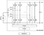
- FIG. 3 is a schematic diagram showing the circuit structure of an ultracapacitor module 1 according to an embodiment of the present application
- FIG. 4 is a schematic diagram showing the circuit structure of an equalization circuit (BC) in the ultracapacitor module 1 according to an embodiment of the present application;
- FIG. 5 is a schematic diagram showing the circuit structure of a DC-DC converter according to an embodiment of the present application.
- FIG. 6 is a schematic diagram showing the circuit structure of a DC-AC inverter according to an embodiment of the present application.
- FIG. 7 is a schematic diagram showing the circuit structure of a switching conversion circuit according to an embodiment of the present application.
- FIG. 8 illustrates a method for controlling automatic rescue and energy saving of an elevator according to an embodiment of the present application.
- the present application proposes an automatic rescue and energy-saving device for an elevator based on a supercapacitor module, which can provide an energy-saving operation of the elevator and a standby power supply for the emergency stop floor of the elevator when a sudden power failure occurs.
- the present application will automatically store the backup power for the emergency shutdown of the elevator power failure and the feedback power generated when the traction motor brakes.
- the present application automatically supplies power stored in the supercapacitor module to the elevator system, causing the elevator system to operate and emergency stop at the nearest floor.
- FIG. 1 is a schematic block diagram of an elevator automatic rescue and energy saving device of the present application.
- 2 is a schematic diagram of the architecture of FIG. 1. 1 and 2, the elevator automatic rescue and energy saving device of the present application is composed of an energy management system 6, a super capacitor module 1, a DC-DC converter 2, a DC-AC inverter 3, and a switch conversion circuit 4, the elevator
- the automatic rescue and energy-saving device is connected to the external three-phase power grid 9 and the motor driver 8.
- the automatic rescue and energy-saving device of the elevator supplies the power of the grid to the motor driver 8 when the power supply of the grid is normal to drive the traction motor 7 to drive the elevator to operate normally, and suddenly the grid is in operation.
- the stored electrical energy is supplied to the motor drive 8 to drive the traction motor 7 and the elevator control system 10 to relieve the operation of the elevator.
- the energy management system 6 is an intelligent control center of the apparatus of the present application for controlling the automatic rescue and energy saving operation of the elevator.
- the energy management system 6 will send a control signal to the switch converter circuit 4 such that the switch converter circuit 4 selects the single phase power source in the three phase grid as the AC power source of the elevator control system 10. Meanwhile, when the power grid is normally powered, the energy management system 6 also controls the DC-DC converter 2 to charge the supercapacitor module 1 to a prescribed backup power, which is used to supply power to the elevator control system 10 when the power grid is suddenly powered off. And traction motor 7.
- the elevator operation is divided into two cases, one for the uplink and one for the downlink.
- the traction motor 7 is in the braking mode, at which time the energy management system 6 controls the DC-DC converter 2 to cause the supercapacitor module 1 to absorb the feedback energy generated by the braking of the traction motor 7.
- the energy management system 6 controls the DC-DC converter 2 to supply the absorbed feedback electric energy to the traction motor, thereby realizing the energy-saving operation of the elevator.
- the energy management system 6 controls the DC-AC inverter 3 to convert the direct current into single-phase alternating current, wherein the direct current is derived from the electric energy stored by the supercapacitor module 1, and controls the switching circuit 4 to control the single phase.
- the one-way alternating current output from the DC-AC inverter 3 is connected to the elevator control system 10 as its single-phase AC power source.
- the energy management system 6 also controls the DC-DC converter 2 to cause the ultracapacitor module 1 to supply the stored backup power to the DC bus connected to the motor driver 8.
- the energy management control system 6 also signals the elevator control system 10 to cause the elevator to be emergencyly parked on the nearest floor, thereby enabling automatic rescue of the elevator upon sudden power outage.
- the signal sent to the elevator control system 10 by the energy management control system 6 can be understood as a voltage signal.
- the voltage signal in the absence of a fault, can be 12 volts or 24 volts, etc.; in the event of a fault, the voltage signal can be zero volts, depending on the elevator control system interface requirements.
- the elevator automatic rescue and energy saving device may further include a super capacitor management system 5, Used to monitor and manage the operation of the Supercapacitor Module 1, which measures and monitors the temperature of each supercapacitor cell and the temperature at different locations of the module. If the supercapacitor management system 5 finds any occurrence of overvoltage, overtemperature, and undertemperature in the supercapacitor module, it immediately sends corresponding fault information to the energy management system 6.
- a super capacitor management system 5 Used to monitor and manage the operation of the Supercapacitor Module 1, which measures and monitors the temperature of each supercapacitor cell and the temperature at different locations of the module. If the supercapacitor management system 5 finds any occurrence of overvoltage, overtemperature, and undertemperature in the supercapacitor module, it immediately sends corresponding fault information to the energy management system 6.
- FIG. 3 shows a schematic diagram of the circuit structure of the ultracapacitor module 1 according to an embodiment of the present application.
- the supercapacitor module 1 is connected to the DC-DC converter 2, through which the standby power required for the emergency stop of the elevator power failure and the feedback energy generated by the traction motor brake are stored, and the power grid suddenly The standby power is released during the power failure for emergency stop of the elevator and release of the feedback power to the traction motor.
- the ultracapacitor module 1 includes a plurality of supercapacitors and equalization circuits connected in parallel.
- the supercapacitor module 1 can be composed of m branches connected in parallel (m is a positive integer), each branch is composed of n units connected in series (n is a positive integer), and each unit is connected by a super capacitor and balanced in parallel.
- the circuit (BC) is composed.
- the supercapacitor can be a supercapacitor cell or can be composed of several supercapacitor cells in parallel.
- FIG. 4 shows a circuit configuration diagram of an equalization circuit (BC) in the ultracapacitor module 1 according to an embodiment of the present application.
- the equalization circuit can be made up of resistors (R1, R2, R3, R4, R5, R6, R7, R8), capacitor (C1), adjustable precision shunt regulator (U1), triode (Q1), MOSFET. (Q2) composition.
- the equalization circuit shown in FIG. 4 above is only one example of the present application, and the present application is not limited thereto.
- the equalization circuit (BC) is used to maintain the normal operation of the supercapacitor connected in parallel therewith. If the voltage of the supercapacitor exceeds the specified value, the triode (Q1) and the MOSFET (Q2) will be turned on, so that the supercapacitor discharges to the resistor (R8), and the supercapacitor voltage is reduced, thereby protecting the supercapacitor voltage. A goal that exceeds the allowed value.
- the equalization circuit (BC) does not operate if the supercapacitor voltage does not exceed the specified value.
- FIG. 5 is a schematic diagram showing the circuit structure of a DC-DC converter according to an embodiment of the present application.
- the DC-DC converter 2 is connected to the supercapacitor module 1, the motor driver 8, and the DC-AC inverter 3, and is controlled by the energy management system 6.
- the DC-DC conversion 2 is composed of an inductor (L1 to LK), a power switching device (T1 to T2K), a power diode (D1 to D2K), a driving circuit, and a control circuit (k is a positive integer), DC-DC.
- the output of the transform 2 can be directly connected to the DC bus of the motor drive 8.
- the power switching device may be a switching device such as an IGBT, a GTO, or a MOSFET, but the present application is not limited thereto.
- the DC-DC converter shown in FIG. 5 above is only an example of the present application, and the present application is not limited thereto.
- the DC-DC converter 2 receives the control signal of the energy management system 6 for converting the voltage of the supercapacitor module 1 into the voltage of the DC bus in the motor driver 8, and also converting the voltage of the DC bus to the voltage of the supercapacitor module 1. .
- the DC-DC converter 2 transfers the electrical energy stored by the supercapacitor module 1 to the traction motor 7 via the DC bus. Conversely, it can also store the feedback energy generated by the traction motor in the supercapacitor module 1.
- FIG. 6 is a schematic diagram showing the circuit structure of a DC-AC inverter according to an embodiment of the present application.
- the DC-AC inverter 3 is connected to the DC-DC converter 2, the motor driver 8, and the switching converter circuit 4, and is controlled by the energy management system 6.
- the DC-AC inverter 3 can be powered by power switching devices (T f1 , T f2 , T f3 , T f4 ), power diodes (D f1 , D f2 , D f3 , D f4 ), and inductance (L f ). , capacitor (C f ), drive circuit and control circuit.
- the DC-AC inverter shown in FIG. 6 above is only one example of the present application, and the present application is not limited thereto.
- the single-phase DC-AC inverter 3 is controlled by the energy management system 6 for inverting the voltage of the ultracapacitor module 1 stored in the DC-DC converter 2 to the DC bus to a single-phase AC voltage, and then The alternating current is supplied to the elevator control system via the switch conversion circuit 4, thereby controlling the emergency stop of the elevator upon sudden power failure.
- FIG. 7 is a schematic diagram showing the circuit structure of a switching conversion circuit according to an embodiment of the present application.
- the switching converter circuit 4 is connected to the grid 9, the elevator control system 10, and is composed of a contactor or power switching device (S1, S2) and a driving circuit.
- the switchover circuit 4 is controlled by the energy management system 6. If the grid is normally powered, the single phase grid from the three phase grid is connected to the elevator control system 10 as its single phase AC source, and if the grid is suddenly powered down, then DC-AC The inverter output is connected to the elevator control system as its single phase AC power source.
- the automatic rescue and energy-saving control method of the elevator is divided into electric energy for saving the elevator operation when the power grid is normally powered, and uses the stored electric energy as the backup power source of the traction motor when the power grid is suddenly powered off and serves as the power source of the elevator control system. So that the elevator control system controls the elevator to run and emergency stop to the nearest floor.
- the energy management system 6 controls the DC-DC converter 2 to charge the super capacitor module 1 to the specified standby power.
- the energy management system 6 sends a control signal to the DC- The DC converter 2, the DC-DC converter 2, transmits the feedback energy generated by the traction motor 7 while braking to the supercapacitor module 1.
- the energy management system 6 sends a control signal to the DC-DC converter 2, and the DC-DC converter 2 supplies the feedback energy stored in the supercapacitor module 1 to the traction motor through the DC bus. .
- the energy management system 6 immediately sends a control signal to the DC-DC converter 2 and the switch conversion circuit 4, and the DC-DC converter 2 transfers the energy stored by the supercapacitor module 1 to the DC bus, and the switch conversion circuit 4
- the DC-AC inverter 3 output is selected as the AC power source of the elevator control system; at the same time, a control signal is sent to the elevator control system 10, forcing the elevator to automatically stop at the nearest floor. If the energy management system 6 receives the relevant fault information from the supercapacitor management system 5, the energy management system 6 will issue a control signal to the DC-DC converter 2, and the DC-DC converter 2 will stop operating. Moreover, the energy management system issues an alarm message.
- the energy control system 6 controls the DC-AC inverter 3 to stop operating.
- the energy control system 6 determines whether the supercapacitor module 1 needs to be charged under normal power supply conditions (for example, the energy control system 6 detects the supercapacitor module voltage through the DC-DC converter to This estimates the electrical energy of the supercapacitor module) to store backup power.
- the electric energy of the supercapacitor module 1 is less than the rescue energy required for the emergency operation of the elevator, it is necessary to control the DC-DC converter to charge the ultracapacitor module 1 to supply the three-phase grid to the motor driver DC through the DC-DC converter.
- the direct current on the bus is supplied to the ultracapacitor module 1 to be charged to the prescribed backup power.
- the rescue power is an electric energy value for the elevator automatic rescue estimated based on the elevator capacity, power, and the like.
- how to store and supply the feedback electrical energy is determined depending on whether the elevator is moving up or down, that is, whether the traction motor is electrically operated or braked.
- the supercapacitor module 1 When the elevator is running down, that is, when the tractor brakes, if the electric energy of the supercapacitor module 1 is less than the brake feedback energy limit, the supercapacitor module 1 can also store electrical energy, and then the DC-DC converter will be controlled on the DC bus.
- the feedback energy generated by the brake operation of the tractor is transmitted to the supercapacitor module 1 for storage.
- the brake feedback power limit represents the maximum capacity allowed by the ultracapacitor module 1. If the electrical energy of the supercapacitor module 1 exceeds the brake feedback energy limit, the feedback energy generated by the traction brake operation is released via the DC bus.
- the DC bus can pass the feedback electric energy through the braking circuit (as shown in FIG. 2, the braking resistor is connected to a switch and then connected to the DC bus, so it is called a braking circuit here). Discharge, thereby keeping the DC bus voltage below its limit.
- the super capacitor module 1 transmits the stored excess feedback electric energy to the DC bus to be supplied to the motor driver, thereby achieving energy saving. Therefore, before supplying the feedback electric energy to the motor driver, it is first determined whether the electric energy of the supercapacitor module 1 is greater than the required rescue energy, and the DC-DC conversion is determined when the electric energy of the supercapacitor module 1 is greater than the required rescue energy. The device transfers the feedback energy of the supercapacitor module to the DC bus of the motor driver.
- the control DC-DC converter stops working, and does not transmit. Feed back energy.
- the energy management system 6 selects the power stored by the supercapacitor module 1 as the rescue power of the traction motor and the elevator control system. At this time, the energy management system 6 sends a control signal to the DC-DC converter 2, The DC-DC converter 2 transfers the electrical energy stored by the ultracapacitor module 1 to the DC bus, the DC-AC inverter 3 starts to work, and then the energy management system 6 issues an instruction to the switching converter circuit 4 to select the DC-AC inverter 3 The output is the AC power source of the elevator control system 10; at the same time, a control signal is sent to the elevator control system 10, forcing the elevator to automatically stop at the nearest floor.
- the present application uses a supercapacitor module, which can provide a stable and reliable elevator rescue power supply when the power grid is suddenly powered off, and can also store the feedback power dissipated during the elevator brake operation, and is electrically operated. This feedback energy is used to save energy.
Landscapes
- Engineering & Computer Science (AREA)
- Automation & Control Theory (AREA)
- Power Engineering (AREA)
- Business, Economics & Management (AREA)
- Emergency Management (AREA)
- Computer Networks & Wireless Communication (AREA)
- Maintenance And Inspection Apparatuses For Elevators (AREA)
- Elevator Control (AREA)
- Inverter Devices (AREA)
Abstract
Description
Claims (18)
- 一种电梯自动解救及节能装置,包括:超级电容器模块,用于存储电能,该电能包括用于电梯断电紧急停靠的备用电能以及牵引电机制动时产生的回馈电能;直流-直流变换器,其连接所述超级电容器模块并连接用于驱动电梯的牵引电机的电机驱动器,用来将所述超级电容器模块的电压转换为所述电机驱动器中直流母线的电压,也用于将所述直流母线的电压转换为所述超级电容器模块的电压;直流-交流逆变器,其连接所述直流-直流变换器,用于将所述直流-直流变换器输出的直流电转换为交流电;开关转换电路,其连接所述直流-交流逆变器和一电网,用于在所述直流-交流逆变器和所述电网之间进行选择切换,以将所述直流-交流逆变器所转换后的交流电输出给一电梯控制系统或将所述电网的电力输出给所述电梯控制系统;能量管理系统,连接所述直流-直流变换器、所述直流-交流逆变器、所述开关转换电路,用于当所述电网正常供电时,控制所述开关转换电路将所述电网连接至所述电梯控制系统作为其交流电源,并控制所述直流-直流变换器对所述超级电容器模块充电至规定的备用电能,并用于当所述电网突然断电时,控制所述直流-直流变换器将来自所述超级电容器模块中的电能转换为直流电传输给所述直流-交流逆变器,控制所述直流-交流逆变器将所述直流电转换为交流电,并控制所述开关转换电路将该交流电连接至所述电梯控制系统以作为其交流电源,同时控制所述直流-直流变换器将来自所述超级电容器模块中的电能供电给所述电机驱动器。
- 根据权利要求1所述的电梯自动解救及节能装置,所述超级电容器模块包括多个并联连接的支路,其中每个支路由多个串联连接的超级电容器单元组成,所述超级电容器单元包括并联连接的超级电容器及均衡电路,其中所述均衡电路用于保持与其并联连接的超级电容器工作在正常的容许范围内。
- 根据权利要求1所述的电梯自动解救及节能装置,所述能量管理系统还用于当所述牵引电机制动时,控制所述直流-直流变换器使所述超级电容器模块存储由牵引电机制动产生的回馈电能,且当所述牵引电机工作于电动模式时,控制所述直流-直流变换器将所述超级电容模块所存储的回馈电能供电给所述牵引电机。
- 根据权利要求3所述的电梯自动解救及节能装置,所述能量管理系统还用于:在牵引机制动运行时,如果所述超级电容器模块的电能小于制动回馈电能限值,则控制所述直流-直流变换器将由于牵引机制动运行所产生的回馈电能传送给所述超级电容器模块存储;否则,将由于牵引机制动运行所产生的回馈电能释放掉;其中所述制动回馈电能限值表示所述超级电容器模块允许的最大容量。
- 根据权利要求3所述的电梯自动解救及节能装置,所述能量管理系统还用于:在 牵引电机电动运行时,确定所述超级电容器模块的电能是否大于用于电梯急救运行所需的解救电能;如果所述超级电容器模块的电能大于所述解救电能,通过所述直流-直流变换器将所述超级电容器模块的回馈电能传送给电机驱动器;否则控制所述直流-直流变换器停止工作。
- 根据权利要求1-5任一项所述的电梯自动解救及节能装置,所述能量管理系统还用于根据所述超级电容器模块的电能大小,确定是否需要向所述超级电容器模块充电;如果所述超级电容器模块的电能小于用于电梯急救运行所需的解救电能,则控制与超级电容器模块相连的直流-直流变换器向超级电容器模块充电;否则,停止向所述超级电容器模块充电。
- 根据权利要求1-5任一项所述的电梯自动解救及节能装置,所述能量管理系统还用于当突然断电时发送指令给电梯控制系统,从而通过电梯控制系统使电梯紧急停靠到最近楼层。
- 根据权利要求1-5任一项所述的电梯自动解救及节能装置,还包括超级电容管理系统,用来监视和管理所述超级电容器模块的运行,在发现所述超级电容器模块出现故障时发送相应的故障信息给所述能量管理系统。
- 根据权利要求1-5任一项所述的电梯自动解救及节能装置,所述直流-直流变换器是一个多相双向功率变换器,其由多个相电路构成,每个相电路包括一个电感和两个功率开关器件。
- 根据权利要求1-5任一项所述的电梯自动解救及节能装置,所述直流-交流逆变器可由功率开关器件、功率二极管、电感、电容器、驱动电路和控制电路组成。
- 根据权利要求1-5任一项所述的电梯自动解救及节能装置,所述开关转换电路由接触器或功率开关器件和驱动电路组成。
- 一种电梯自动解救及节能控制方法,包括:当电网正常供电时,选择三相电网中的单相电作为电梯控制系统的交流电源;控制直流-直流变换器对与其连接的超级电容器模块充电至规定的备用电能;当电网突然中断时,选择使用所述超级电容器模块存储的电能作为牵引机和电梯控制系统的解救电能。
- 根据权利要求12所述的电梯自动解救及节能控制方法,当电网正常供电时,还包括:根据所述超级电容器模块的电能大小,确定是否需要向所述超级电容器模块充电;如果所述超级电容器模块的电能小于用于电梯急救运行所需的解救电能,则控制与超级电容器模块相连的直流-直流变换器向超级电容器模块充电;否则,停止向所述超级电容器模块充电。
- 根据权利要求12所述的电梯自动解救及节能控制方法,当电网突然中断时,所述方法还包括:发出控制信号给依次连接的直流-直流变换器、直流-交流逆变器、开关转换电路,从而使得所述直流-直流变换器将超级电容器模块存储的电能传递至电机驱动器 和所述直流-交流逆变器,所述开关转换电路将选择所述直流-交流逆变器的输出作为电梯控制系统的交流电源;同时发出控制信号给所述电梯控制系统,迫使电梯自动紧急停靠于最近的楼层。
- 根据权利要求12-14任一项所述的电梯自动解救及节能控制方法,还包括:在牵引机制动运行时,如果所述超级电容器模块的电能小于制动回馈电能限值,则控制所述直流-直流变换器将由于牵引机制动运行所产生的回馈电能传送给所述超级电容器模块存储;否则,将由于牵引机制动运行所产生的回馈电能释放掉;其中所述制动回馈电能限值表示所述超级电容器模块允许的最大容量
- 根据权利要求12-14任一项所述的电梯自动解救及节能控制方法,还包括:在牵引电机电动运行时,确定所述超级电容器模块的电能是否大于用于电梯急救运行所需的解救电能;如果所述超级电容器模块的电能大于所述解救电能,通过所述直流-直流变换器将所述超级电容器模块的回馈电能传送给电机驱动器;否则控制所述直流-直流变换器停止工作。
- 一种超级电容器模块,所述超级电容器模块存储用于电梯断电紧急停靠的备用电能以及牵引电机制动产生的回馈电能,所述超级电容器模块包括多个并联连接的支路,其中每个支路由多个串联连接的超级电容器单元组成,所述超级电容器单元包括并联连接的超级电容器及均衡电路,其中所述均衡电路用于保持与其并联连接的超级电容器工作在正常的容许范围内。
- 根据权利要求17所述的超级电容器模块,所述超级电容器为超级电容器单体或由并联连接的多个超级电容器单体组成。
Priority Applications (3)
| Application Number | Priority Date | Filing Date | Title |
|---|---|---|---|
| EP15781010.2A EP3156358A4 (en) | 2015-08-07 | 2015-09-10 | Elevator automatic rescue and energy-saving device and control method for same and super capacitor module |
| US15/750,897 US11046553B2 (en) | 2015-08-07 | 2015-09-10 | Elevator automatic rescue and energy-saving device and control method for same and super capacitor module |
| KR1020157035977A KR101930252B1 (ko) | 2015-08-07 | 2015-09-10 | 엘리베이터 자동 구조 및 절전 장치와 그 제어 방법 및 슈퍼 커패시터 모듈 |
Applications Claiming Priority (4)
| Application Number | Priority Date | Filing Date | Title |
|---|---|---|---|
| CN201520595650.5 | 2015-08-07 | ||
| CN201510484927.1A CN105098967B (zh) | 2015-08-07 | 2015-08-07 | 电梯自动解救及节能装置以及其控制方法、以及超级电容器模块 |
| CN201510484927.1 | 2015-08-07 | ||
| CN201520595650.5U CN204928347U (zh) | 2015-08-07 | 2015-08-07 | 电梯自动解救及节能装置、以及超级电容器模块 |
Publications (1)
| Publication Number | Publication Date |
|---|---|
| WO2017024653A1 true WO2017024653A1 (zh) | 2017-02-16 |
Family
ID=57614108
Family Applications (1)
| Application Number | Title | Priority Date | Filing Date |
|---|---|---|---|
| PCT/CN2015/089365 Ceased WO2017024653A1 (zh) | 2015-08-07 | 2015-09-10 | 电梯自动解救及节能装置以及其控制方法、以及超级电容器模块 |
Country Status (5)
| Country | Link |
|---|---|
| US (1) | US11046553B2 (zh) |
| EP (1) | EP3156358A4 (zh) |
| KR (1) | KR101930252B1 (zh) |
| TW (1) | TWI636945B (zh) |
| WO (1) | WO2017024653A1 (zh) |
Cited By (3)
| Publication number | Priority date | Publication date | Assignee | Title |
|---|---|---|---|---|
| CN107528383A (zh) * | 2017-10-16 | 2017-12-29 | 山西腾然科技有限公司 | 一种矿井提升机用超级电容ups电源装置 |
| CN114865763A (zh) * | 2022-04-29 | 2022-08-05 | 重庆中科超容科技有限公司 | 一种超级电容器储能电梯节能系统及方法 |
| CN116961201A (zh) * | 2023-07-28 | 2023-10-27 | 联桥科技有限公司 | 一种电梯外置势能回收系统及方法 |
Families Citing this family (25)
| Publication number | Priority date | Publication date | Assignee | Title |
|---|---|---|---|---|
| CN108349685B (zh) * | 2015-11-06 | 2021-03-09 | 通力股份公司 | 电梯能量解决方案 |
| KR102336042B1 (ko) * | 2017-03-31 | 2021-12-07 | 비나텍주식회사 | 슈퍼 커패시터 모듈을 포함하는 승강기용 비상구출 운전장치 |
| US11053096B2 (en) | 2017-08-28 | 2021-07-06 | Otis Elevator Company | Automatic rescue and charging system for elevator drive |
| DK3524560T3 (da) * | 2018-02-13 | 2021-03-15 | Kone Corp | Elevator med backup-strømforsyning |
| CN108545564B (zh) * | 2018-04-19 | 2019-07-30 | 上海新时达电气股份有限公司 | 一种电梯物联网设备 |
| CN108808820B (zh) * | 2018-08-27 | 2023-11-24 | 南通科技职业学院 | 一种基于超级电容的电梯节能系统 |
| EP3640176B1 (en) | 2018-10-19 | 2022-02-16 | Otis Elevator Company | Power management in an elevator system |
| EP3640175B1 (en) * | 2018-10-19 | 2023-01-04 | Otis Elevator Company | Decentralized power management in an elevator system |
| EP3653557B1 (en) | 2018-11-14 | 2022-04-20 | Otis Elevator Company | Elevator alarm systems |
| US11840423B2 (en) | 2018-12-14 | 2023-12-12 | Otis Elevator Company | Hybrid energy storage system architectures |
| CN110011406A (zh) * | 2019-04-30 | 2019-07-12 | 上海稳利达电力电子有限公司 | 一种老旧小区加装电梯所需的电源转换装置 |
| EP3976417B1 (de) * | 2019-05-29 | 2023-12-06 | Sew-Eurodrive GmbH & Co. KG | Antriebssystem und verfahren zum betreiben eines antriebssystems |
| CN110589653B (zh) * | 2019-09-20 | 2024-09-03 | 广东亚太西奥电梯有限公司 | 一种智能脱困电梯及其独立脱困装置和智能电梯脱困方法 |
| CN112249827B (zh) * | 2020-10-27 | 2023-08-29 | 杭州优迈科技有限公司 | 一种电梯应急救援控制电路和控制方法 |
| KR102460286B1 (ko) | 2021-01-07 | 2022-10-31 | 이주수 | 엘리베이터 보호용 과전압 차단장치 |
| EP4047167A1 (en) | 2021-02-19 | 2022-08-24 | Face S.r.l. | Electronic system to activate the emergency opening and/or closing of automatic doors |
| US11404906B1 (en) | 2021-05-17 | 2022-08-02 | SK Hynix Inc. | Power failure protection system for solid state drives |
| KR102584073B1 (ko) * | 2021-09-27 | 2023-10-05 | (주)에스엔 | Ict 기반 에너지 저장 장치 모니터링 시스템 |
| CN115231399B (zh) * | 2022-07-04 | 2024-10-01 | 惠州市远大电梯有限公司 | 节能电梯控制系统 |
| JP7405195B1 (ja) | 2022-08-05 | 2023-12-26 | フジテック株式会社 | 乗客コンベア |
| EP4332042B1 (en) * | 2022-09-05 | 2026-04-29 | Otis Elevator Company | Setting a rescue time period |
| CN116513899A (zh) * | 2023-03-31 | 2023-08-01 | 西子电梯科技有限公司 | 电梯电源控制方法、系统、计算机设备和存储介质 |
| CN116505625B (zh) * | 2023-06-27 | 2023-12-08 | 广东省特种设备检测研究院中山检测院 | 一种电梯运行节能与应急供电的控制方法及控制系统 |
| TWI900112B (zh) * | 2024-07-05 | 2025-10-01 | 盟立自動化股份有限公司 | 變頻器的節能控制電路及其節能控制方法 |
| CN121485034B (zh) * | 2026-01-09 | 2026-04-21 | 合肥华思系统股份有限公司 | 储能系统及储能系统的控制方法 |
Citations (6)
| Publication number | Priority date | Publication date | Assignee | Title |
|---|---|---|---|---|
| US20100044160A1 (en) * | 2007-02-13 | 2010-02-25 | Otis Elevator Company | Automatic rescue operation for a regenerative drive system |
| CN101807821A (zh) * | 2010-03-05 | 2010-08-18 | 南京理工大学 | 电梯节能系统 |
| CN201850017U (zh) * | 2010-11-16 | 2011-06-01 | 南通维科机电制造有限公司 | 一种新型的超级电容式电梯节能控制装置 |
| CN102211724A (zh) * | 2011-03-14 | 2011-10-12 | 上海德圣米高电梯有限公司 | 一种使用超级电容器的新型节能电梯 |
| CN103193123A (zh) * | 2013-04-08 | 2013-07-10 | 金璐 | 一种电梯节能型应急平层一体机 |
| CN103441521A (zh) * | 2013-08-31 | 2013-12-11 | 深圳先进储能材料国家工程研究中心有限公司 | 电梯能量回收利用保障系统 |
Family Cites Families (24)
| Publication number | Priority date | Publication date | Assignee | Title |
|---|---|---|---|---|
| JP2656684B2 (ja) | 1991-06-12 | 1997-09-24 | 三菱電機株式会社 | エレベータの停電時運転装置 |
| KR100312771B1 (ko) | 1998-12-15 | 2002-05-09 | 장병우 | 엘리베이터의정전운전제어장치및방법 |
| CA2400762C (en) | 2000-03-31 | 2009-05-26 | Inventio Ag | Emergency current supply equipment for lift installations |
| AU2003251306A1 (en) * | 2002-05-20 | 2003-12-12 | Good Ideas Llc | Ultracapacitor balancing circuit |
| JP4544884B2 (ja) | 2004-03-18 | 2010-09-15 | 東芝エレベータ株式会社 | エレベータ制御装置 |
| US7540356B2 (en) | 2005-10-18 | 2009-06-02 | Thyssen Elevator Capital Corp. | Method and apparatus to prevent or minimize the entrapment of passengers in elevators during a power failure |
| US20090014252A1 (en) * | 2006-01-30 | 2009-01-15 | Vedula Sastry V | Elevator drive assembly including a capacitive energy storage device |
| KR100858191B1 (ko) | 2006-11-03 | 2008-09-10 | 현대자동차주식회사 | 연료전지-슈퍼 커패시터 하이브리드 차량의 슈퍼 커패시터제어 장치 |
| US8146714B2 (en) * | 2006-12-14 | 2012-04-03 | Otis Elevator Company | Elevator system including regenerative drive and rescue operation circuit for normal and power failure conditions |
| US8613344B2 (en) * | 2008-08-15 | 2013-12-24 | Otis Elevator Company | Line current and energy storage control for an elevator drive |
| WO2010059138A1 (en) | 2008-11-18 | 2010-05-27 | Otis Elevator Company | On demand elevator load shedding |
| ES2382430B1 (es) | 2009-12-21 | 2013-01-30 | Orona, S. Coop | Metodo y sistema de gestion de energia de un motor electrico |
| CN101917020B (zh) | 2010-08-04 | 2012-10-03 | 长沙理工大学 | 电梯能量回馈、无功补偿及断电应急运行方法及系统 |
| FR2967532B1 (fr) * | 2010-11-15 | 2012-11-16 | Schneider Toshiba Inverter | Variateur de vitesse dote d'un module a super-condensateurs |
| KR101865223B1 (ko) * | 2011-10-05 | 2018-06-08 | 삼성전자주식회사 | 항 c-Met 인간화 항체 및 그의 용도 |
| TWI439008B (zh) | 2011-11-16 | 2014-05-21 | Univ Nat Formosa | 雙向換流電路及電動載具驅動系統 |
| ES2665979T3 (es) | 2012-06-01 | 2018-04-30 | Otis Elevator Company | Sistema de ascensor con un dispositivo de almacenamiento de energía |
| CN102723763A (zh) | 2012-06-04 | 2012-10-10 | 天津大学 | 超级电容储能式电梯快速充电保护控制器 |
| US9966758B2 (en) * | 2012-06-11 | 2018-05-08 | Panduit Corp. | Capacitor-based UPS |
| CN102923537B (zh) | 2012-11-13 | 2014-04-23 | 天津大学 | 超级电容储能式电梯一体化驱动控制装置 |
| KR101460656B1 (ko) | 2013-04-10 | 2014-11-11 | 비나텍주식회사 | 복합형 에너지저장장치에 적용되는 울트라커패시터 팩의 감지장치 |
| CN204516591U (zh) | 2014-06-06 | 2015-07-29 | 武汉威科奇新动力能源科技有限公司 | 超级电容器模块 |
| CN204928347U (zh) | 2015-08-07 | 2015-12-30 | 富华德电子有限公司 | 电梯自动解救及节能装置、以及超级电容器模块 |
| CN106477435B (zh) * | 2015-08-25 | 2019-12-10 | 奥的斯电梯公司 | 电梯轿厢电力供应 |
-
2015
- 2015-09-10 EP EP15781010.2A patent/EP3156358A4/en not_active Withdrawn
- 2015-09-10 KR KR1020157035977A patent/KR101930252B1/ko not_active Expired - Fee Related
- 2015-09-10 WO PCT/CN2015/089365 patent/WO2017024653A1/zh not_active Ceased
- 2015-09-10 US US15/750,897 patent/US11046553B2/en active Active
- 2015-10-06 TW TW104132799A patent/TWI636945B/zh not_active IP Right Cessation
Patent Citations (6)
| Publication number | Priority date | Publication date | Assignee | Title |
|---|---|---|---|---|
| US20100044160A1 (en) * | 2007-02-13 | 2010-02-25 | Otis Elevator Company | Automatic rescue operation for a regenerative drive system |
| CN101807821A (zh) * | 2010-03-05 | 2010-08-18 | 南京理工大学 | 电梯节能系统 |
| CN201850017U (zh) * | 2010-11-16 | 2011-06-01 | 南通维科机电制造有限公司 | 一种新型的超级电容式电梯节能控制装置 |
| CN102211724A (zh) * | 2011-03-14 | 2011-10-12 | 上海德圣米高电梯有限公司 | 一种使用超级电容器的新型节能电梯 |
| CN103193123A (zh) * | 2013-04-08 | 2013-07-10 | 金璐 | 一种电梯节能型应急平层一体机 |
| CN103441521A (zh) * | 2013-08-31 | 2013-12-11 | 深圳先进储能材料国家工程研究中心有限公司 | 电梯能量回收利用保障系统 |
Cited By (5)
| Publication number | Priority date | Publication date | Assignee | Title |
|---|---|---|---|---|
| CN107528383A (zh) * | 2017-10-16 | 2017-12-29 | 山西腾然科技有限公司 | 一种矿井提升机用超级电容ups电源装置 |
| CN107528383B (zh) * | 2017-10-16 | 2023-11-24 | 山西腾然科技有限公司 | 一种矿井提升机用超级电容ups电源装置 |
| CN114865763A (zh) * | 2022-04-29 | 2022-08-05 | 重庆中科超容科技有限公司 | 一种超级电容器储能电梯节能系统及方法 |
| CN116961201A (zh) * | 2023-07-28 | 2023-10-27 | 联桥科技有限公司 | 一种电梯外置势能回收系统及方法 |
| CN116961201B (zh) * | 2023-07-28 | 2024-03-08 | 联桥科技有限公司 | 一种电梯外置势能回收系统及方法 |
Also Published As
| Publication number | Publication date |
|---|---|
| US11046553B2 (en) | 2021-06-29 |
| TWI636945B (zh) | 2018-10-01 |
| TW201706198A (zh) | 2017-02-16 |
| EP3156358A1 (en) | 2017-04-19 |
| KR101930252B1 (ko) | 2018-12-18 |
| US20180229968A1 (en) | 2018-08-16 |
| EP3156358A4 (en) | 2017-12-13 |
| KR20170028239A (ko) | 2017-03-13 |
Similar Documents
| Publication | Publication Date | Title |
|---|---|---|
| TWI636945B (zh) | 電梯自動解救及節能裝置以及其控制方法、以及超級電容器模塊 | |
| CN105098967B (zh) | 电梯自动解救及节能装置以及其控制方法、以及超级电容器模块 | |
| JP5735061B2 (ja) | 電車給電システム | |
| CN102123929B (zh) | 电梯驱动器的线路电流和能量存储控制 | |
| KR20090087064A (ko) | 구조 작동 회로를 포함하는 엘리베이터 시스템 | |
| CN204928347U (zh) | 电梯自动解救及节能装置、以及超级电容器模块 | |
| CN108988477B (zh) | 能量反馈型电梯下应急电源装置供电的方法及装置和电梯 | |
| CN107528383B (zh) | 一种矿井提升机用超级电容ups电源装置 | |
| CN103441521A (zh) | 电梯能量回收利用保障系统 | |
| WO2010059139A1 (en) | Power management in elevators during marginal quality power conditions | |
| WO2017161842A1 (zh) | 一种轮胎式龙门起重机三动力混合节能系统 | |
| CN116054323A (zh) | 基于超级电容的电梯再生电能存储再利用系统 | |
| CN115231399A (zh) | 节能电梯控制系统及其控制方法 | |
| CN111483899A (zh) | 电梯系统 | |
| CN106849273A (zh) | 一种双电源的混合供电型移动供电装置 | |
| CN112701992B (zh) | 电机供电系统 | |
| HK1212824B (zh) | 电梯自动解救及节能装置以及其控制方法、以及超级电容器模块 | |
| CN113765462A (zh) | 一种电梯应急平层用集成超级电容的四象限变频器系统 | |
| CN105731263B (zh) | 一种吊机的控制方法及控制装置 | |
| CN218024797U (zh) | 电梯电气系统以及电梯系统 | |
| CN218664846U (zh) | 一种电梯平层节能保护装置 | |
| CN121282979A (zh) | 一种用于绞车动能回收的储能系统 | |
| CN120527870A (zh) | 用于变频器的节能装置、能量控制方法及升降设备 | |
| CN119117862A (zh) | 一种直流电梯系统及一种直流电梯 | |
| RU2644385C2 (ru) | Преобразователь частоты со встроенным источником резервного питания |
Legal Events
| Date | Code | Title | Description |
|---|---|---|---|
| REEP | Request for entry into the european phase |
Ref document number: 2015781010 Country of ref document: EP |
|
| WWE | Wipo information: entry into national phase |
Ref document number: 2015781010 Country of ref document: EP |
|
| ENP | Entry into the national phase |
Ref document number: 20157035977 Country of ref document: KR Kind code of ref document: A |
|
| 121 | Ep: the epo has been informed by wipo that ep was designated in this application |
Ref document number: 15781010 Country of ref document: EP Kind code of ref document: A1 |
|
| WWE | Wipo information: entry into national phase |
Ref document number: 15750897 Country of ref document: US |
|
| NENP | Non-entry into the national phase |
Ref country code: DE |