WO2017026536A1 - 変速装置および車両 - Google Patents
変速装置および車両 Download PDFInfo
- Publication number
- WO2017026536A1 WO2017026536A1 PCT/JP2016/073681 JP2016073681W WO2017026536A1 WO 2017026536 A1 WO2017026536 A1 WO 2017026536A1 JP 2016073681 W JP2016073681 W JP 2016073681W WO 2017026536 A1 WO2017026536 A1 WO 2017026536A1
- Authority
- WO
- WIPO (PCT)
- Prior art keywords
- dog
- speed
- gear
- slider
- shaft
- Prior art date
- Legal status (The legal status is an assumption and is not a legal conclusion. Google has not performed a legal analysis and makes no representation as to the accuracy of the status listed.)
- Ceased
Links
Images

Classifications
-
- F—MECHANICAL ENGINEERING; LIGHTING; HEATING; WEAPONS; BLASTING
- F16—ENGINEERING ELEMENTS AND UNITS; GENERAL MEASURES FOR PRODUCING AND MAINTAINING EFFECTIVE FUNCTIONING OF MACHINES OR INSTALLATIONS; THERMAL INSULATION IN GENERAL
- F16H—GEARING
- F16H3/00—Toothed gearings for conveying rotary motion with variable gear ratio or for reversing rotary motion
- F16H3/02—Toothed gearings for conveying rotary motion with variable gear ratio or for reversing rotary motion without gears having orbital motion
- F16H3/08—Toothed gearings for conveying rotary motion with variable gear ratio or for reversing rotary motion without gears having orbital motion exclusively or essentially with continuously meshing gears, that can be disengaged from their shafts
- F16H3/087—Toothed gearings for conveying rotary motion with variable gear ratio or for reversing rotary motion without gears having orbital motion exclusively or essentially with continuously meshing gears, that can be disengaged from their shafts characterised by the disposition of the gears
- F16H3/089—Toothed gearings for conveying rotary motion with variable gear ratio or for reversing rotary motion without gears having orbital motion exclusively or essentially with continuously meshing gears, that can be disengaged from their shafts characterised by the disposition of the gears all of the meshing gears being supported by a pair of parallel shafts, one being the input shaft and the other the output shaft, there being no countershaft involved
-
- B—PERFORMING OPERATIONS; TRANSPORTING
- B62—LAND VEHICLES FOR TRAVELLING OTHERWISE THAN ON RAILS
- B62M—RIDER PROPULSION OF WHEELED VEHICLES OR SLEDGES; POWERED PROPULSION OF SLEDGES OR SINGLE-TRACK CYCLES; TRANSMISSIONS SPECIALLY ADAPTED FOR SUCH VEHICLES
- B62M11/00—Transmissions characterised by the use of interengaging toothed wheels or frictionally-engaging wheels
- B62M11/04—Transmissions characterised by the use of interengaging toothed wheels or frictionally-engaging wheels of changeable ratio
- B62M11/06—Transmissions characterised by the use of interengaging toothed wheels or frictionally-engaging wheels of changeable ratio with spur gear wheels
-
- F—MECHANICAL ENGINEERING; LIGHTING; HEATING; WEAPONS; BLASTING
- F16—ENGINEERING ELEMENTS AND UNITS; GENERAL MEASURES FOR PRODUCING AND MAINTAINING EFFECTIVE FUNCTIONING OF MACHINES OR INSTALLATIONS; THERMAL INSULATION IN GENERAL
- F16D—COUPLINGS FOR TRANSMITTING ROTATION; CLUTCHES; BRAKES
- F16D11/00—Clutches in which the members have interengaging parts
- F16D11/08—Clutches in which the members have interengaging parts actuated by moving a non-rotating part axially
- F16D11/10—Clutches in which the members have interengaging parts actuated by moving a non-rotating part axially with clutching members movable only axially
-
- F—MECHANICAL ENGINEERING; LIGHTING; HEATING; WEAPONS; BLASTING
- F16—ENGINEERING ELEMENTS AND UNITS; GENERAL MEASURES FOR PRODUCING AND MAINTAINING EFFECTIVE FUNCTIONING OF MACHINES OR INSTALLATIONS; THERMAL INSULATION IN GENERAL
- F16D—COUPLINGS FOR TRANSMITTING ROTATION; CLUTCHES; BRAKES
- F16D11/00—Clutches in which the members have interengaging parts
- F16D11/14—Clutches in which the members have interengaging parts with clutching members movable only axially
-
- F—MECHANICAL ENGINEERING; LIGHTING; HEATING; WEAPONS; BLASTING
- F16—ENGINEERING ELEMENTS AND UNITS; GENERAL MEASURES FOR PRODUCING AND MAINTAINING EFFECTIVE FUNCTIONING OF MACHINES OR INSTALLATIONS; THERMAL INSULATION IN GENERAL
- F16D—COUPLINGS FOR TRANSMITTING ROTATION; CLUTCHES; BRAKES
- F16D21/00—Systems comprising a plurality of actuated clutches
- F16D21/02—Systems comprising a plurality of actuated clutches for interconnecting three or more shafts or other transmission members in different ways
- F16D21/04—Systems comprising a plurality of actuated clutches for interconnecting three or more shafts or other transmission members in different ways with a shaft carrying a number of rotatable transmission members, e.g. gears, each of which can be connected to the shaft by a clutching member or members between the shaft and the hub of the transmission member
-
- F—MECHANICAL ENGINEERING; LIGHTING; HEATING; WEAPONS; BLASTING
- F16—ENGINEERING ELEMENTS AND UNITS; GENERAL MEASURES FOR PRODUCING AND MAINTAINING EFFECTIVE FUNCTIONING OF MACHINES OR INSTALLATIONS; THERMAL INSULATION IN GENERAL
- F16D—COUPLINGS FOR TRANSMITTING ROTATION; CLUTCHES; BRAKES
- F16D23/00—Details of mechanically-actuated clutches not specific for one distinct type
- F16D23/12—Mechanical clutch-actuating mechanisms arranged outside the clutch as such
-
- F—MECHANICAL ENGINEERING; LIGHTING; HEATING; WEAPONS; BLASTING
- F16—ENGINEERING ELEMENTS AND UNITS; GENERAL MEASURES FOR PRODUCING AND MAINTAINING EFFECTIVE FUNCTIONING OF MACHINES OR INSTALLATIONS; THERMAL INSULATION IN GENERAL
- F16D—COUPLINGS FOR TRANSMITTING ROTATION; CLUTCHES; BRAKES
- F16D23/00—Details of mechanically-actuated clutches not specific for one distinct type
- F16D23/12—Mechanical clutch-actuating mechanisms arranged outside the clutch as such
- F16D23/14—Clutch-actuating sleeves or bearings; Actuating members directly connected to clutch-actuating sleeves or bearings
-
- F—MECHANICAL ENGINEERING; LIGHTING; HEATING; WEAPONS; BLASTING
- F16—ENGINEERING ELEMENTS AND UNITS; GENERAL MEASURES FOR PRODUCING AND MAINTAINING EFFECTIVE FUNCTIONING OF MACHINES OR INSTALLATIONS; THERMAL INSULATION IN GENERAL
- F16H—GEARING
- F16H3/00—Toothed gearings for conveying rotary motion with variable gear ratio or for reversing rotary motion
- F16H3/02—Toothed gearings for conveying rotary motion with variable gear ratio or for reversing rotary motion without gears having orbital motion
- F16H3/08—Toothed gearings for conveying rotary motion with variable gear ratio or for reversing rotary motion without gears having orbital motion exclusively or essentially with continuously meshing gears, that can be disengaged from their shafts
- F16H3/083—Toothed gearings for conveying rotary motion with variable gear ratio or for reversing rotary motion without gears having orbital motion exclusively or essentially with continuously meshing gears, that can be disengaged from their shafts with radially acting and axially controlled clutching members, e.g. sliding keys
-
- F—MECHANICAL ENGINEERING; LIGHTING; HEATING; WEAPONS; BLASTING
- F16—ENGINEERING ELEMENTS AND UNITS; GENERAL MEASURES FOR PRODUCING AND MAINTAINING EFFECTIVE FUNCTIONING OF MACHINES OR INSTALLATIONS; THERMAL INSULATION IN GENERAL
- F16H—GEARING
- F16H3/00—Toothed gearings for conveying rotary motion with variable gear ratio or for reversing rotary motion
- F16H3/02—Toothed gearings for conveying rotary motion with variable gear ratio or for reversing rotary motion without gears having orbital motion
- F16H3/08—Toothed gearings for conveying rotary motion with variable gear ratio or for reversing rotary motion without gears having orbital motion exclusively or essentially with continuously meshing gears, that can be disengaged from their shafts
- F16H3/087—Toothed gearings for conveying rotary motion with variable gear ratio or for reversing rotary motion without gears having orbital motion exclusively or essentially with continuously meshing gears, that can be disengaged from their shafts characterised by the disposition of the gears
- F16H3/091—Toothed gearings for conveying rotary motion with variable gear ratio or for reversing rotary motion without gears having orbital motion exclusively or essentially with continuously meshing gears, that can be disengaged from their shafts characterised by the disposition of the gears including a single countershaft
-
- F—MECHANICAL ENGINEERING; LIGHTING; HEATING; WEAPONS; BLASTING
- F16—ENGINEERING ELEMENTS AND UNITS; GENERAL MEASURES FOR PRODUCING AND MAINTAINING EFFECTIVE FUNCTIONING OF MACHINES OR INSTALLATIONS; THERMAL INSULATION IN GENERAL
- F16H—GEARING
- F16H37/00—Combinations of mechanical gearings, not provided for in groups F16H1/00 - F16H35/00
- F16H37/02—Combinations of mechanical gearings, not provided for in groups F16H1/00 - F16H35/00 comprising essentially only toothed or friction gearings
-
- F—MECHANICAL ENGINEERING; LIGHTING; HEATING; WEAPONS; BLASTING
- F16—ENGINEERING ELEMENTS AND UNITS; GENERAL MEASURES FOR PRODUCING AND MAINTAINING EFFECTIVE FUNCTIONING OF MACHINES OR INSTALLATIONS; THERMAL INSULATION IN GENERAL
- F16H—GEARING
- F16H61/00—Control functions within control units of change-speed- or reversing-gearings for conveying rotary motion ; Control of exclusively fluid gearing, friction gearing, gearings with endless flexible members or other particular types of gearing
- F16H61/26—Generation or transmission of movements for final actuating mechanisms
- F16H61/28—Generation or transmission of movements for final actuating mechanisms with at least one movement of the final actuating mechanism being caused by a non-mechanical force, e.g. power-assisted
- F16H61/32—Electric motors , actuators or related electrical control means therefor
-
- F—MECHANICAL ENGINEERING; LIGHTING; HEATING; WEAPONS; BLASTING
- F16—ENGINEERING ELEMENTS AND UNITS; GENERAL MEASURES FOR PRODUCING AND MAINTAINING EFFECTIVE FUNCTIONING OF MACHINES OR INSTALLATIONS; THERMAL INSULATION IN GENERAL
- F16H—GEARING
- F16H63/00—Control outputs from the control unit to change-speed- or reversing-gearings for conveying rotary motion or to other devices than the final output mechanism
- F16H63/02—Final output mechanisms therefor; Actuating means for the final output mechanisms
- F16H63/08—Multiple final output mechanisms being moved by a single common final actuating mechanism
- F16H63/16—Multiple final output mechanisms being moved by a single common final actuating mechanism the final output mechanisms being successively actuated by progressive movement of the final actuating mechanism
- F16H63/18—Multiple final output mechanisms being moved by a single common final actuating mechanism the final output mechanisms being successively actuated by progressive movement of the final actuating mechanism the final actuating mechanism comprising cams
-
- F—MECHANICAL ENGINEERING; LIGHTING; HEATING; WEAPONS; BLASTING
- F16—ENGINEERING ELEMENTS AND UNITS; GENERAL MEASURES FOR PRODUCING AND MAINTAINING EFFECTIVE FUNCTIONING OF MACHINES OR INSTALLATIONS; THERMAL INSULATION IN GENERAL
- F16H—GEARING
- F16H63/00—Control outputs from the control unit to change-speed- or reversing-gearings for conveying rotary motion or to other devices than the final output mechanism
- F16H63/02—Final output mechanisms therefor; Actuating means for the final output mechanisms
- F16H63/30—Constructional features of the final output mechanisms
-
- F—MECHANICAL ENGINEERING; LIGHTING; HEATING; WEAPONS; BLASTING
- F16—ENGINEERING ELEMENTS AND UNITS; GENERAL MEASURES FOR PRODUCING AND MAINTAINING EFFECTIVE FUNCTIONING OF MACHINES OR INSTALLATIONS; THERMAL INSULATION IN GENERAL
- F16H—GEARING
- F16H63/00—Control outputs from the control unit to change-speed- or reversing-gearings for conveying rotary motion or to other devices than the final output mechanism
- F16H63/02—Final output mechanisms therefor; Actuating means for the final output mechanisms
- F16H63/30—Constructional features of the final output mechanisms
- F16H63/304—Constructional features of the final output mechanisms the final output mechanisms comprising elements moved by electrical or magnetic force
-
- B—PERFORMING OPERATIONS; TRANSPORTING
- B60—VEHICLES IN GENERAL
- B60Y—INDEXING SCHEME RELATING TO ASPECTS CROSS-CUTTING VEHICLE TECHNOLOGY
- B60Y2200/00—Type of vehicle
- B60Y2200/10—Road Vehicles
- B60Y2200/12—Motorcycles, Trikes; Quads; Scooters
-
- F—MECHANICAL ENGINEERING; LIGHTING; HEATING; WEAPONS; BLASTING
- F16—ENGINEERING ELEMENTS AND UNITS; GENERAL MEASURES FOR PRODUCING AND MAINTAINING EFFECTIVE FUNCTIONING OF MACHINES OR INSTALLATIONS; THERMAL INSULATION IN GENERAL
- F16C—SHAFTS; FLEXIBLE SHAFTS; ELEMENTS OR CRANKSHAFT MECHANISMS; ROTARY BODIES OTHER THAN GEARING ELEMENTS; BEARINGS
- F16C19/00—Bearings with rolling contact, for exclusively rotary movement
- F16C19/02—Bearings with rolling contact, for exclusively rotary movement with bearing balls essentially of the same size in one or more circular rows
- F16C19/04—Bearings with rolling contact, for exclusively rotary movement with bearing balls essentially of the same size in one or more circular rows for radial load mainly
- F16C19/06—Bearings with rolling contact, for exclusively rotary movement with bearing balls essentially of the same size in one or more circular rows for radial load mainly with a single row or balls
-
- F—MECHANICAL ENGINEERING; LIGHTING; HEATING; WEAPONS; BLASTING
- F16—ENGINEERING ELEMENTS AND UNITS; GENERAL MEASURES FOR PRODUCING AND MAINTAINING EFFECTIVE FUNCTIONING OF MACHINES OR INSTALLATIONS; THERMAL INSULATION IN GENERAL
- F16C—SHAFTS; FLEXIBLE SHAFTS; ELEMENTS OR CRANKSHAFT MECHANISMS; ROTARY BODIES OTHER THAN GEARING ELEMENTS; BEARINGS
- F16C19/00—Bearings with rolling contact, for exclusively rotary movement
- F16C19/02—Bearings with rolling contact, for exclusively rotary movement with bearing balls essentially of the same size in one or more circular rows
- F16C19/04—Bearings with rolling contact, for exclusively rotary movement with bearing balls essentially of the same size in one or more circular rows for radial load mainly
- F16C19/08—Bearings with rolling contact, for exclusively rotary movement with bearing balls essentially of the same size in one or more circular rows for radial load mainly with two or more rows of balls
-
- F—MECHANICAL ENGINEERING; LIGHTING; HEATING; WEAPONS; BLASTING
- F16—ENGINEERING ELEMENTS AND UNITS; GENERAL MEASURES FOR PRODUCING AND MAINTAINING EFFECTIVE FUNCTIONING OF MACHINES OR INSTALLATIONS; THERMAL INSULATION IN GENERAL
- F16C—SHAFTS; FLEXIBLE SHAFTS; ELEMENTS OR CRANKSHAFT MECHANISMS; ROTARY BODIES OTHER THAN GEARING ELEMENTS; BEARINGS
- F16C19/00—Bearings with rolling contact, for exclusively rotary movement
- F16C19/52—Bearings with rolling contact, for exclusively rotary movement with devices affected by abnormal or undesired conditions
- F16C19/527—Bearings with rolling contact, for exclusively rotary movement with devices affected by abnormal or undesired conditions related to vibration and noise
-
- F—MECHANICAL ENGINEERING; LIGHTING; HEATING; WEAPONS; BLASTING
- F16—ENGINEERING ELEMENTS AND UNITS; GENERAL MEASURES FOR PRODUCING AND MAINTAINING EFFECTIVE FUNCTIONING OF MACHINES OR INSTALLATIONS; THERMAL INSULATION IN GENERAL
- F16C—SHAFTS; FLEXIBLE SHAFTS; ELEMENTS OR CRANKSHAFT MECHANISMS; ROTARY BODIES OTHER THAN GEARING ELEMENTS; BEARINGS
- F16C2326/00—Articles relating to transporting
- F16C2326/01—Parts of vehicles in general
-
- F—MECHANICAL ENGINEERING; LIGHTING; HEATING; WEAPONS; BLASTING
- F16—ENGINEERING ELEMENTS AND UNITS; GENERAL MEASURES FOR PRODUCING AND MAINTAINING EFFECTIVE FUNCTIONING OF MACHINES OR INSTALLATIONS; THERMAL INSULATION IN GENERAL
- F16C—SHAFTS; FLEXIBLE SHAFTS; ELEMENTS OR CRANKSHAFT MECHANISMS; ROTARY BODIES OTHER THAN GEARING ELEMENTS; BEARINGS
- F16C2326/00—Articles relating to transporting
- F16C2326/20—Land vehicles
-
- F—MECHANICAL ENGINEERING; LIGHTING; HEATING; WEAPONS; BLASTING
- F16—ENGINEERING ELEMENTS AND UNITS; GENERAL MEASURES FOR PRODUCING AND MAINTAINING EFFECTIVE FUNCTIONING OF MACHINES OR INSTALLATIONS; THERMAL INSULATION IN GENERAL
- F16C—SHAFTS; FLEXIBLE SHAFTS; ELEMENTS OR CRANKSHAFT MECHANISMS; ROTARY BODIES OTHER THAN GEARING ELEMENTS; BEARINGS
- F16C2361/00—Apparatus or articles in engineering in general
- F16C2361/65—Gear shifting, change speed gear, gear box
-
- F—MECHANICAL ENGINEERING; LIGHTING; HEATING; WEAPONS; BLASTING
- F16—ENGINEERING ELEMENTS AND UNITS; GENERAL MEASURES FOR PRODUCING AND MAINTAINING EFFECTIVE FUNCTIONING OF MACHINES OR INSTALLATIONS; THERMAL INSULATION IN GENERAL
- F16D—COUPLINGS FOR TRANSMITTING ROTATION; CLUTCHES; BRAKES
- F16D23/00—Details of mechanically-actuated clutches not specific for one distinct type
- F16D23/12—Mechanical clutch-actuating mechanisms arranged outside the clutch as such
- F16D2023/123—Clutch actuation by cams, ramps or ball-screw mechanisms
-
- F—MECHANICAL ENGINEERING; LIGHTING; HEATING; WEAPONS; BLASTING
- F16—ENGINEERING ELEMENTS AND UNITS; GENERAL MEASURES FOR PRODUCING AND MAINTAINING EFFECTIVE FUNCTIONING OF MACHINES OR INSTALLATIONS; THERMAL INSULATION IN GENERAL
- F16H—GEARING
- F16H61/00—Control functions within control units of change-speed- or reversing-gearings for conveying rotary motion ; Control of exclusively fluid gearing, friction gearing, gearings with endless flexible members or other particular types of gearing
- F16H61/04—Smoothing ratio shift
- F16H2061/0474—Smoothing ratio shift by smoothing engagement or release of positive clutches; Methods or means for shock free engagement of dog clutches
-
- F—MECHANICAL ENGINEERING; LIGHTING; HEATING; WEAPONS; BLASTING
- F16—ENGINEERING ELEMENTS AND UNITS; GENERAL MEASURES FOR PRODUCING AND MAINTAINING EFFECTIVE FUNCTIONING OF MACHINES OR INSTALLATIONS; THERMAL INSULATION IN GENERAL
- F16H—GEARING
- F16H61/00—Control functions within control units of change-speed- or reversing-gearings for conveying rotary motion ; Control of exclusively fluid gearing, friction gearing, gearings with endless flexible members or other particular types of gearing
- F16H61/26—Generation or transmission of movements for final actuating mechanisms
- F16H61/28—Generation or transmission of movements for final actuating mechanisms with at least one movement of the final actuating mechanism being caused by a non-mechanical force, e.g. power-assisted
- F16H2061/2869—Cam or crank gearing
-
- F—MECHANICAL ENGINEERING; LIGHTING; HEATING; WEAPONS; BLASTING
- F16—ENGINEERING ELEMENTS AND UNITS; GENERAL MEASURES FOR PRODUCING AND MAINTAINING EFFECTIVE FUNCTIONING OF MACHINES OR INSTALLATIONS; THERMAL INSULATION IN GENERAL
- F16H—GEARING
- F16H63/00—Control outputs from the control unit to change-speed- or reversing-gearings for conveying rotary motion or to other devices than the final output mechanism
- F16H63/02—Final output mechanisms therefor; Actuating means for the final output mechanisms
- F16H63/30—Constructional features of the final output mechanisms
- F16H63/304—Constructional features of the final output mechanisms the final output mechanisms comprising elements moved by electrical or magnetic force
- F16H2063/3056—Constructional features of the final output mechanisms the final output mechanisms comprising elements moved by electrical or magnetic force using cam or crank gearing
-
- F—MECHANICAL ENGINEERING; LIGHTING; HEATING; WEAPONS; BLASTING
- F16—ENGINEERING ELEMENTS AND UNITS; GENERAL MEASURES FOR PRODUCING AND MAINTAINING EFFECTIVE FUNCTIONING OF MACHINES OR INSTALLATIONS; THERMAL INSULATION IN GENERAL
- F16H—GEARING
- F16H63/00—Control outputs from the control unit to change-speed- or reversing-gearings for conveying rotary motion or to other devices than the final output mechanism
- F16H63/02—Final output mechanisms therefor; Actuating means for the final output mechanisms
- F16H63/30—Constructional features of the final output mechanisms
- F16H2063/3093—Final output elements, i.e. the final elements to establish gear ratio, e.g. coupling sleeves or other means establishing coupling to shaft
-
- F—MECHANICAL ENGINEERING; LIGHTING; HEATING; WEAPONS; BLASTING
- F16—ENGINEERING ELEMENTS AND UNITS; GENERAL MEASURES FOR PRODUCING AND MAINTAINING EFFECTIVE FUNCTIONING OF MACHINES OR INSTALLATIONS; THERMAL INSULATION IN GENERAL
- F16H—GEARING
- F16H2200/00—Transmissions for multiple ratios
- F16H2200/0013—Transmissions for multiple ratios specially adapted for rear-wheel-driven vehicles
-
- F—MECHANICAL ENGINEERING; LIGHTING; HEATING; WEAPONS; BLASTING
- F16—ENGINEERING ELEMENTS AND UNITS; GENERAL MEASURES FOR PRODUCING AND MAINTAINING EFFECTIVE FUNCTIONING OF MACHINES OR INSTALLATIONS; THERMAL INSULATION IN GENERAL
- F16H—GEARING
- F16H2200/00—Transmissions for multiple ratios
- F16H2200/003—Transmissions for multiple ratios characterised by the number of forward speeds
- F16H2200/0052—Transmissions for multiple ratios characterised by the number of forward speeds the gear ratios comprising six forward speeds
-
- F—MECHANICAL ENGINEERING; LIGHTING; HEATING; WEAPONS; BLASTING
- F16—ENGINEERING ELEMENTS AND UNITS; GENERAL MEASURES FOR PRODUCING AND MAINTAINING EFFECTIVE FUNCTIONING OF MACHINES OR INSTALLATIONS; THERMAL INSULATION IN GENERAL
- F16H—GEARING
- F16H63/00—Control outputs from the control unit to change-speed- or reversing-gearings for conveying rotary motion or to other devices than the final output mechanism
- F16H63/02—Final output mechanisms therefor; Actuating means for the final output mechanisms
- F16H63/30—Constructional features of the final output mechanisms
- F16H63/32—Gear shift yokes, e.g. shift forks
Definitions
- the present invention relates to a transmission mounted on a vehicle and a vehicle including the transmission.
- a transmission mounted on a vehicle includes a drive shaft that extends in the axial direction and is connected to a power source (such as an engine or a motor) via a clutch mechanism, and a driven shaft that extends in the axial direction.
- a power source such as an engine or a motor
- Each of the drive shaft and the driven shaft is provided with a number of gears corresponding to the number of shift stages.
- a gear pair is configured by meshing a driving gear provided on the driving shaft and a driven gear provided on the driven shaft for each gear. The gear ratio of each gear pair is different. In the transmission, only the gear pair corresponding to the gear stage transmits power according to the selected gear stage.
- the transmission disclosed in Patent Document 1 includes a shift drum and a shift fork.
- the shift drum is rotated by the reciprocating movement of the shift rod.
- a plurality of cam grooves are formed on the outer peripheral surface of the shift drum.
- One end of the shift fork is positioned in the cam groove of the shift drum.
- the other end of the shift fork is connected to a predetermined transmission gear disposed on the main shaft, for example.
- the predetermined transmission gear is provided on the main shaft so as to be movable in the axial direction with respect to the main shaft.
- the shift drum changes its rotation angle according to the selected gear position.
- the cam groove is formed on the outer peripheral surface of the shift drum such that the position of the main shaft in the axial direction changes according to the rotation angle.
- the predetermined transmission gear is provided on the main shaft so as not to rotate relative to the main shaft.
- the predetermined driven gear that meshes with the predetermined transmission gear is provided on the drive shaft so as to be rotatable relative to the drive shaft.
- Drive gears arranged in the axial direction of the main shaft with respect to the predetermined transmission gear are provided to be rotatable relative to the main shaft.
- a driven gear that meshes with the drive gear is provided on the drive shaft so as not to rotate relative to the drive shaft.
- the predetermined transmission gear has a dog convex portion.
- the dog convex portion extends toward the drive gear.
- the drive gear is provided with a dog recess.
- the one drive gear moved in the axial direction by the shift fork is tilted with respect to the other drive gear. Therefore, the dog convex portion provided on the one drive gear is also inclined with respect to the dog concave portion provided on the other drive gear. Due to the inclination of the dog convex portion provided on the one driving gear, the contact state between the dog convex portion and the dog concave portion provided on the other driving gear is changed. Therefore, the sound per dog is difficult to be constant.
- the transmission can be configured to suppress the noise per dog while reducing the driver's discomfort caused by the sound per dog.
- the present inventor has thought that the sound per dog can be suppressed by reducing the moment of inertia of the member involved in the collision. This is because, if the moment of inertia of the member involved in the collision is small, the collision energy directly related to the sound per dog can be reduced.
- the present inventor first considered separating the dog convex portion from the one drive gear described above. That is, the present inventor has considered a configuration of a transmission in which a slider that is movable in the axial direction of the drive shaft is disposed between a pair of drive gears, and the slider includes a dog convex portion.
- the shift fork connects the other end to the slider.
- the present inventor has increased the number of dog convex portions and dog concave portions to disperse the stress generated when each dog convex portion and each dog concave portion mesh with each other. It was found that can be suppressed more.
- the other drive gear (spinning gear) with which the dog convex portion of the slider comes into contact can rotate relative to the drive shaft provided with the other gear, and may be inclined with respect to the drive shaft.
- the other driving gear meshes with a driven gear (fixed gear) that cannot rotate relative to the driven shaft
- the inclination of the other driving gear increases at the meshing point. I realized that.
- the stress generated when the dog convex portions and the dog concave portions are engaged with each other is increased by increasing the number of the dog convex portions and the dog concave portions as described above. be able to. Therefore, the sound per dog can be further suppressed.
- the present inventor has determined that the drive shaft is fixed on the basis of a line connecting the meshing point between the driven gear (fixed gear) and the other drive gear (idling gear) and the shaft center of the drive shaft.
- a configuration in which a slider is disposed between a pair of drive gears provided side by side in the axial direction on the drive shaft and a dog convex portion is provided on the slider is described as an example.
- a slider may be arranged between a pair of driven gears provided side by side in the axial direction on the driven shaft. In this case, the slider moves in the axial direction of the driven shaft with respect to the driven gear that is an idle gear.
- the driving gear or the driven gear may be provided with a dog convex portion, and the slider may be provided with a dog concave portion.
- the slider is not limited to the configuration in which the slider is arranged between the pair of driving gears or between the pair of driven gears, but the slider can move with respect to one driving gear or the driven gear that is an idle gear.
- An arranged configuration may be used.
- a transmission according to an embodiment of the present invention is a transmission mounted on a vehicle.
- the transmission includes an axially extending drive shaft connected to a power source via a clutch mechanism, a driven shaft extending in the axial direction, and one of the drive shaft and the driven shaft.
- the fixed gear fixed in the axial direction and provided integrally and rotatably, and the other of the drive shaft and the driven shaft is fixed in the axial direction and provided so as to be relatively rotatable.
- An idler gear that meshes with a gear, and a slider that is provided on the other shaft so as to be movable in the axial direction and to be integrally rotatable, and does not transmit power directly to the gear provided on the one shaft.
- a shift shaft formed in a cylindrical shape or a column shape extending in the axial direction and having a guide groove extending in the circumferential direction on the outer peripheral surface, and configured to be rotatable about the drum shaft extending in the axial direction.
- a plurality of dog protrusions are provided on one of the slider and the idle gear.
- the other of the slider and the idler gear is provided with a plurality of dog recesses that mesh with at least a part of the plurality of dog protrusions.
- the slider is moved to a position where at least one of the plurality of dog convex portions and at least one of the plurality of dog concave portions mesh with each other as the shift fork moves in the guide groove according to the rotation of the shift drum. It is configured to be movable in the axial direction.
- the idle gear is integrated with the slider and the other shaft in a state where at least one of the plurality of dog convex portions and at least one of the plurality of dog concave portions are engaged with each other by movement of the slider in the axial direction. Rotate with.
- the plurality of dog convex portions and the plurality of dog concave portions are fixed to the other shaft in the axial direction when the shift fork moves in the guide groove according to the rotation of the shift drum.
- the fixed gear and the fixed gear as viewed from the axial direction in a state where at least one of the plurality of dog convex portions and at least one of the plurality of dog concave portions are engaged with each other by moving toward the idle gear.
- the transmission according to the embodiment of the present invention it is possible to reduce the driver's uncomfortable feeling caused by the dog hitting sound while suppressing the dog hitting sound.
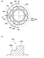
- FIG. 8 A) equivalent figure of the transmission which concerns on other embodiment, (B) It is a figure which shows an example of the cross-sectional shape of a dog convex part.
- a vehicle 1 (an example of a vehicle) according to an embodiment will be described with reference to FIGS.
- the scale is appropriately changed to make each member a recognizable size.
- “left” and “right” respectively represent “left” and “right” as viewed from the driver who has boarded the vehicle 1.
- FIG. 1 shows the appearance of the vehicle 1 when the vehicle 1 is viewed from the right side.
- An arrow F indicates the front direction of the vehicle 1.
- An arrow B indicates the backward direction of the vehicle 1.
- An arrow U indicates the upward direction of the vehicle 1.
- An arrow D indicates the downward direction of the vehicle 1.
- the vehicle 1 is a motorcycle including a front wheel 21 and a rear wheel 22.
- the vehicle 1 includes an internal combustion engine 3 (an example of a power source) and a transmission 4.
- the transmission 4 is mounted on the vehicle 1.
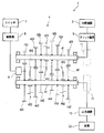
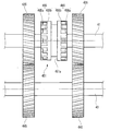
- FIG. 2 shows a configuration of the transmission 4 according to the present embodiment. Specifically, FIG. 2A schematically shows the configuration of the transmission 4. FIG. 2B schematically shows configurations of a first slider 451 and a fifth speed drive gear 425 described later of the transmission 4.
- FIG. 3 is an enlarged view of FIG. 2 (a).
- the transmission 4 includes a drive shaft 41.
- the vehicle 1 includes a clutch mechanism 5.
- the drive shaft 41 is connected to the internal combustion engine 3 via the clutch mechanism 5.
- the direction in which the drive shaft 41 extends is defined as “axial direction”.
- the clutch mechanism 5 is configured to be switchable between a connected state in which the rotation of the crankshaft in the internal combustion engine 3 is transmitted to the drive shaft 41 and a disconnected state in which the rotation of the crankshaft is not transmitted to the drive shaft 41.
- the transmission 4 includes a first speed drive gear 421, a second speed drive gear 422, a third speed drive gear 423, a fourth speed drive gear 424, a fifth speed drive gear 425, and a sixth speed drive gear 426.
- the first speed drive gear 421, the second speed drive gear 422, the third speed drive gear 423, the fourth speed drive gear 424, the fifth speed drive gear 425, and the sixth speed drive gear 426 are arranged side by side on the drive shaft 41 in the axial direction. ing.
- the transmission 4 includes a driven shaft 43.
- the driven shaft 43 extends in the axial direction. That is, the driven shaft 43 extends in parallel with the driving shaft 41.
- the driven shaft 43 extends in the axial direction of the driving shaft 41.
- the drive shaft 41 or the driven shaft 43 extending in the axial direction means that the drive shaft 41 or the driven shaft 43 is long in the axial direction.
- the transmission 4 includes a first speed driven gear 441, a second speed driven gear 442, a third speed driven gear 443, a fourth speed driven gear 444, a fifth speed driven gear 445, and a sixth speed driven gear 446. Yes.
- the first speed driven gear 441, the second speed driven gear 442, the third speed driven gear 443, the fourth speed driven gear 444, the fifth speed driven gear 445, and the sixth speed driven gear 446 are on the driven shaft 43. They are arranged side by side in the axial direction.
- the first speed driven gear 441 is always meshed with the first speed driven gear 421.
- the second speed driven gear 442 is always meshed with the second speed driven gear 422.
- the third speed driven gear 443 is always in mesh with the third speed driven gear 423.
- the fourth speed driven gear 444 is always meshed with the fourth speed driven gear 424.
- the fifth speed driven gear 445 always meshes with the fifth speed driven gear 425.
- the six-speed driven gear 446 is always meshed with the six-speed driven gear 426.
- the first speed drive gear 421 is not rotatable with respect to the drive shaft 41. That is, the first speed drive gear 421 can rotate integrally with the drive shaft 41.
- the first speed driven gear 441 is rotatable relative to the driven shaft 43.
- the second speed drive gear 422 cannot rotate with respect to the drive shaft 41. That is, the second-speed drive gear 422 can rotate integrally with the drive shaft 41.
- the second speed driven gear 442 is rotatable relative to the driven shaft 43.
- the third-speed drive gear 423 cannot rotate with respect to the drive shaft 41. That is, the third speed drive gear 423 can rotate integrally with the drive shaft 41.
- the third speed driven gear 443 can rotate relative to the driven shaft 43.
- the fourth speed drive gear 424 cannot rotate with respect to the drive shaft 41. That is, the four-speed drive gear 424 can rotate integrally with the drive shaft 41.
- the four-speed driven gear 444 can rotate relative to the driven shaft 43.
- the fifth-speed drive gear 425 can rotate relative to the drive shaft 41.
- the fifth speed driven gear 445 cannot rotate with respect to the driven shaft 43. That is, the fifth speed driven gear 445 can rotate integrally with the driven shaft 43.
- the six-speed drive gear 426 can rotate relative to the drive shaft 41.
- the six-speed driven gear 446 cannot rotate with respect to the driven shaft 43. That is, the six-speed driven gear 446 can rotate integrally with the driven shaft 43.
- the first speed drive gear 421, the second speed drive gear 422, and the fifth speed driven gear 445 are examples of fixed gears.
- the third speed driving gear 423, the fourth speed driving gear 424, and the sixth speed driven gear 446 are examples of the second fixed gear.
- the first-speed driven gear 441, the second-speed driven gear 442, and the fifth-speed driven gear 425 are examples of idle gears that mesh with the fixed gear.
- the third-speed driven gear 443, the fourth-speed driven gear 444, and the sixth-speed driven gear 426 are examples of a second idler gear that meshes with the second fixed gear.
- the transmission 4 includes a first slider 451.
- the first slider 451 is disposed on the drive shaft 41 between a fifth speed drive gear 425 (an example of a first drive gear) and a sixth speed drive gear 426 (an example of a second drive gear).
- the first slider 451 is movable in the axial direction on the drive shaft 41.
- the first slider 451 is not rotatable with respect to the drive shaft 41. That is, the first slider 451 can rotate integrally with the drive shaft 41.
- the transmission 4 includes a second slider 452.
- the second slider 452 is disposed on the driven shaft 43 between a first speed driven gear 441 (an example of a first driven gear) and a third speed driven gear 443 (an example of a second driven gear). ing.
- the second slider 452 is movable in the axial direction on the driven shaft 43.
- the second slider 452 cannot rotate with respect to the driven shaft 43. That is, the second slider 452 can rotate integrally with the driven shaft 43.
- the transmission 4 includes a third slider 453.
- the third slider 453 is disposed on the driven shaft 43 between a second speed driven gear 442 (an example of a first driven gear) and a fourth speed driven gear 444 (an example of a second driven gear). ing.
- the third slider 453 is movable on the driven shaft 43 in the axial direction.
- the third slider 453 cannot rotate with respect to the driven shaft 43. That is, the third slider 453 can rotate integrally with the driven shaft 43.
- the first slider 451, the second slider 452, and the third slider 453 are examples of sliders.
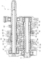
- FIG. 4 is a diagram showing a more detailed configuration of the transmission 4.
- FIG. 4 is a view showing the transmission 4 in a cross section including an axis extending in the axial direction of the drive shaft 41 and the driven shaft 43.
- the transmission 4 includes a fifth speed dog convex portion 465 and a fifth speed dog concave portion 475.
- the fifth speed dog convex portion 465 (an example of the dog convex portion) is provided on the first slider 451.
- the fifth speed dog recess 475 is provided in the fifth speed drive gear 425.
- the transmission 4 includes a six-speed dog convex portion 466 and a six-speed dog concave portion 476.
- a six-speed dog protrusion 466 (an example of a second dog protrusion) is provided on the first slider 451.
- a six-speed dog recess 476 (an example of a second dog recess) is provided in the six-speed drive gear 426.
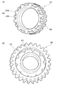
- FIG. 5A is a perspective view showing the appearance of the first slider 451.
- the first slider 451 is annular.
- FIG. 5B is a perspective view showing the appearance of the fifth-speed drive gear 425.
- FIG. 6 shows a five-speed drive gear 425, a six-speed drive gear 426, and a first slider 451 arranged on the drive shaft 41, and a five-speed driven gear 445 and a six-speed driven gear arranged on the driven shaft 43. It is a figure shown with the drive gear 446.
- FIG. 5A is a perspective view showing the appearance of the first slider 451.
- the first slider 451 is annular.
- FIG. 5B is a perspective view showing the appearance of the fifth-speed drive gear 425.
- FIG. 6 shows a five-speed drive gear 425, a six-speed drive gear 426, and a first slider 451 arranged on the drive shaft 41, and a five-speed driven gear 445 and a six-speed driven gear arranged on the driven shaft 43
- the first slider 451 is provided with a plurality of five-speed dog convex portions 465 arranged side by side in the circumferential direction.
- the plurality of five-speed dog convex portions 465 include two types of five-speed dog convex portions 465 a and 465 b having different lengths along the axial direction. In the axial direction, the length of the fifth speed dog convex portion 465a is longer than the length of the fifth speed dog convex portion 465b.
- the 5-speed dog convex portions 465a and the 5-speed dog convex portions 465b are provided on the first slider 451 so as to be alternately arranged in the circumferential direction.
- the first slider 451 is provided with a plurality of six-speed dog convex portions 466 arranged in the circumferential direction around the drive shaft 41.
- the plurality of six-speed dog convex portions 466 include two types of six-speed dog convex portions 466a and 466b having different lengths along the axial direction. In the axial direction, the length of the six-speed dog convex portion 466a is longer than the length of the six-speed dog convex portion 466b.
- Six-speed dog convex portions 466a and six-speed dog convex portions 466b are provided on the first slider 451 so as to be alternately arranged in the circumferential direction.
- the fifth speed drive gear 425 is provided with a plurality of fifth speed dog recesses 475 arranged side by side in the circumferential direction of the fifth speed drive gear 425.
- the number of the plurality of fifth speed dog concave portions 475 is half the number of the plurality of fifth speed dog convex portions 465. That is, each five-speed dog recess 475 is configured to accommodate two five-speed dog protrusions 465.
- the six-speed drive gear 426 is provided with a plurality of six-speed dog recesses 476 arranged side by side in the circumferential direction of the six-speed drive gear 426. .
- the number of the plurality of six-speed dog concave portions 476 is half of the number of the plurality of six-speed dog convex portions 466. That is, each six-speed dog recess 476 is configured to be able to accommodate two six-speed dog protrusions 466.
- the transmission 4 includes a first-speed dog convex portion 461 and a first-speed dog concave portion 471.
- the first speed dog convex portion 461 (an example of the dog convex portion) is provided on the second slider 452.
- the first speed dog recess 471 is provided in the first speed driven gear 441.
- the transmission 4 includes a third-speed dog convex portion 463 and a third-speed dog concave portion 473.
- the third speed dog convex portion 463 (an example of the second dog convex portion) is provided on the second slider 452.
- Third-speed dog recess 473 is provided in third-speed driven gear 443.
- the second slider 452 is annular.
- the second slider 452 is provided with a plurality of first-speed dog convex portions 461 arranged in the circumferential direction.
- the plurality of first-speed dog convex portions 461 include two types of first-speed dog convex portions having different lengths along the axial direction of the drive shaft 41.
- the relatively long first-speed dog protrusions and the relatively short first-speed dog protrusions are provided on the second slider 452 so as to be alternately arranged in the circumferential direction.
- the second slider 452 is provided with a plurality of three-speed dog convex portions 463 arranged side by side in the circumferential direction.
- the plurality of three-speed dog convex portions 463 include two types of three-speed dog convex portions having different lengths along the axial direction.
- the relatively long three-speed dog convex portion and the relatively short three-speed dog convex portion are provided on the second slider 452 so as to be alternately arranged in the circumferential direction.
- the first-speed driven gear 441 is provided with a plurality of first-speed dog recesses 471 aligned in the circumferential direction of the first-speed driven gear 441. ing.
- the number of the plurality of first-speed dog concave portions 471 is half the number of the plurality of first-speed dog convex portions 461. That is, each first speed dog recess 471 is configured to accommodate two first speed dog protrusions 461.
- the third-speed driven gear 443 is provided with a plurality of third-speed dog recesses 473 arranged side by side in the circumferential direction of the third-speed driven gear 443.
- the number of the plurality of third-speed dog concave portions 473 is half the number of the plurality of third-speed dog convex portions 463. That is, each three-speed dog recess 473 is configured to accommodate two three-speed dog protrusions 463.
- the transmission 4 includes a second-speed dog convex portion 462 and a second-speed dog concave portion 472.
- the second-speed dog protrusion 462 (an example of a dog protrusion) is provided on the third slider 453.
- Second-speed dog recess 472 is provided in second-speed driven gear 442.
- the transmission 4 includes a four-speed dog convex portion 464 and a four-speed dog concave portion 474.
- the fourth speed dog convex portion 464 (an example of the second dog convex portion) is provided on the third slider 453.
- a four-speed dog recess 474 (an example of a second dog recess) is provided in the four-speed driven gear 444.
- the third slider 453 is annular.
- the third slider 453 is provided with a plurality of second-speed dog convex portions 462 arranged in the circumferential direction.
- the plurality of second-speed dog convex portions 462 include two types of second-speed dog convex portions having different lengths along the axial direction of the driven shaft 43.
- the relatively long second-speed dog convex portion and the relatively short second-speed dog convex portion are provided on the third slider 453 so as to be alternately arranged in the circumferential direction.
- the third slider 453 is provided with a plurality of four-speed dog convex portions 464 arranged in the circumferential direction.
- the plurality of four-speed dog convex portions 464 include two types of four-speed dog convex portions having different lengths along the axial direction.
- the relatively long four-speed dog convex portions and the relatively short four-speed dog convex portions are provided on the third slider 453 so as to be alternately arranged in the circumferential direction.
- the second speed driven gear 442 is provided with a plurality of second speed dog recesses 472 arranged side by side in the circumferential direction of the second speed driven gear 442. ing.
- the number of the plurality of second speed dog concave portions 472 is half of the number of the plurality of second speed dog convex portions 462. That is, each two-speed dog recess 472 is configured to accommodate two two-speed dog protrusions 462.
- the four-speed driven gear 444 is provided with a plurality of four-speed dog recesses 474 arranged in the circumferential direction of the four-speed driven gear 444.
- the number of the plurality of four-speed dog concave portions 474 is half of the number of the plurality of four-speed dog convex portions 464.
- each four-speed dog recess 474 is configured to accommodate two four-speed dog protrusions 464.
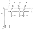
- the transmission 4 includes a shift drum 48.
- FIG. 7 shows a specific configuration of the shift drum 48.
- the shift drum 48 is cylindrical.
- the shift drum 48 has a drum shaft 48a extending in the axial direction.
- the shift drum 48 can rotate around the drum shaft 48a.
- a first guide groove 481, a second guide groove 482, and a third guide groove 483 are formed on the outer peripheral surface of the shift drum 48.
- the first guide groove 481, the second guide groove 482, and the third guide groove 483 are positioned in the direction along the drum shaft 48a (that is, the axial direction) according to the rotation angle of the shift drum 48 around the drum shaft 48a. Is provided on the outer peripheral surface of the drum shift 48 so as to change.
- the outer peripheral surface of the shift drum 48 is a side surface surrounding the drum shaft 48 a in the cylindrical shift drum 48.
- the transmission 4 includes a first shift fork 491, a second shift fork 492, and a third shift fork 493.
- the first shift fork 491 extends from the shift drum 48 toward the first slider 451.
- the second shift fork 492 extends from the shift drum 48 toward the second slider 452.
- the third shift fork 493 extends from the shift drum 48 toward the third slider 453.
- the term "extending from the shift drum toward the slider" means that one end of the shift fork in the longitudinal direction is connected to the shift drum and the other end of the shift fork in the longitudinal direction is connected to the slider. Means the state.
- One end of the first shift fork 491 in the longitudinal direction is positioned in the first guide groove 481 of the shift drum 48.
- One end of the second shift fork 492 in the longitudinal direction is positioned in the second guide groove 482 of the shift drum 48.
- One end in the longitudinal direction of the third shift fork 493 is positioned in the third guide groove 483 of the shift drum 48.
- the first slider 451 has a first fork receiving groove 451a.
- a second fork receiving groove 452a is formed in the second slider 452.
- a third fork receiving groove 453 a is formed in the third slider 453.
- the other end in the longitudinal direction of the first shift fork 491 is connected to the first fork receiving groove 451a of the first slider 451, as indicated by a two-dot chain line.
- the other end in the longitudinal direction of the second shift fork 492 is connected to the second fork receiving groove 452a of the second slider 452.
- the other end in the longitudinal direction of the third shift fork 493 is connected to the third fork receiving groove 453a of the third slider 453.
- first shift fork 491 connects the shift drum 48 and the first slider 451.
- the second shift fork 492 connects the shift drum 48 and the second slider 452.
- the third shift fork 493 connects the shift drum 48 and the third slider 453.
- the transmission 4 of the vehicle 1 in the present embodiment is configured to be capable of six-speed transmission. That is, the gear ratio of the first speed drive gear 421 and the first speed driven gear 441, the gear ratio of the second speed drive gear 422 and the second speed driven gear 442, the gear ratio of the third speed drive gear 423 and the third speed driven gear 443,
- the transmission ratio of the fourth speed driving gear 424 and the fourth speed driven gear 444, the transmission ratio of the fifth speed driving gear 425 and the fifth speed driven gear 445, and the transmission ratio of the sixth speed driving gear 426 and the sixth speed driven gear 446 are different. is doing.
- the vehicle 1 includes a handle 6.
- the handle 6 is configured to change the direction of the front wheel 21 in accordance with the operation of the driver. As the direction of the front wheel 21 changes, the traveling direction of the vehicle 1 changes.
- the vehicle 1 includes a switch 7, a control unit 8, and an electric actuator 9.
- the switch 7 is provided on the handle 6.
- the switch 7 is configured to output a signal for causing the transmission 4 to perform a shift operation when operated by a driver.
- the control unit 8 is configured to output a signal for controlling the operation of the electric actuator 9 in accordance with a signal input from the switch 7.
- the electric actuator 9 is connected to the shift drum 48 via a rod 9a.
- the electric actuator 9 is configured to rotate the shift drum 48 around the drum shaft 48a in accordance with a signal input from the control unit 8 via the rod 9a. That is, the electric actuator 9 is configured to rotate the shift drum 48 according to the operation of the switch 7.
- the rotation angle of the shift drum 48 is determined according to the selected gear position.
- the position of the fork 493 changes. Accordingly, the first slider 451 moves on the drive shaft 41 and the second slider 452 and the third slider 453 move on the driven shaft 43 according to the rotation angle of the shift drum 48 around the drum shaft 48a. .
- the second shift fork 492 moves the second slider 452 along the driven shaft 43.
- the first-speed dog convex portion 461 provided on the second slider 452 meshes with the first-speed dog concave portion 471 provided on the first-speed driven gear 441.
- the third-speed dog convex portion 463 and the third-speed dog concave portion 473 provided on the third-speed driven gear 443 do not mesh with each other. Accordingly, the third speed driven gear 443 rotates idly with respect to the driven shaft 43.
- the first shift fork 491 positions the first slider 451 in the neutral position.
- the fifth speed dog convex portion 465 and the fifth speed dog concave portion 475 do not mesh with each other
- the sixth speed dog convex portion 466 and the sixth speed dog concave portion 476 do not mesh with each other. Therefore, the fifth speed drive gear 425 and the sixth speed drive gear 426 are idled with respect to the drive shaft 41.
- the third shift fork 493 positions the third slider 453 at the neutral position.
- the second speed dog convex portion 462 and the second speed dog concave portion 472 do not mesh with each other, and the fourth speed dog convex portion 464 and the fourth speed dog concave portion 474 also do not mesh with each other. Therefore, the second speed driven gear 442 and the fourth speed driven gear 444 are idled with respect to the driven shaft 43.
- the meshing between the dog convex portion and the dog concave portion means that the dog convex portion and the dog concave portion are in contact with each other at least partially to transmit power.
- the vehicle 1 includes an output mechanism 10.
- the output mechanism 10 is connected to the rear wheel 22.
- the output mechanism 10 includes an output gear 10a.
- the output gear 10 a is provided on the driven shaft 43.
- the output gear 10 a is not rotatable with respect to the driven shaft 43.
- the power transmitted to the driven shaft 43 via the first speed driving gear 421 and the first speed driven gear 441 is transmitted to the rear wheel 22 via the output mechanism 10 including the output gear 10a.
- the third shift fork 493 moves the third slider 453 along the driven shaft 43.
- the second speed dog convex portion 462 provided on the third slider 453 meshes with the second speed dog concave portion 472 provided on the second speed driven gear 442.
- the four-speed dog convex portion 464 and the four-speed dog concave portion 474 provided on the four-speed driven gear 444 do not mesh with each other. Therefore, the four-speed driven gear 444 rotates idly with respect to the driven shaft 43.
- the first shift fork 491 positions the first slider 451 in the neutral position.
- the fifth speed dog convex portion 465 and the fifth speed dog concave portion 475 do not mesh with each other
- the sixth speed dog convex portion 466 and the sixth speed dog concave portion 476 do not mesh with each other. Therefore, the fifth speed drive gear 425 and the sixth speed drive gear 426 are idled with respect to the drive shaft 41.
- the second shift fork 492 positions the second slider 452 at the neutral position.
- the first speed dog convex portion 461 and the first speed dog concave portion 471 do not mesh with each other, and the third speed dog convex portion 463 and the third speed dog concave portion 473 also do not mesh with each other. Therefore, the first-speed driven gear 441 and the third-speed driven gear 443 are idled with respect to the driven shaft 43.
- the power transmitted to the driven shaft 43 via the second speed driving gear 422 and the second speed driven gear 442 is transmitted to the rear wheel 22 via the output mechanism 10 including the output gear 10a.
- the second shift fork 492 moves the second slider 452 along the driven shaft 43.
- the third speed dog convex portion 463 provided on the second slider 452 meshes with the third speed dog concave portion 473 provided on the third speed driven gear 443.
- the first-speed dog convex portion 461 and the first-speed dog concave portion 471 provided on the first-speed driven gear 441 do not mesh with each other. Accordingly, the first speed driven gear 441 rotates idly with respect to the driven shaft 43.
- the first shift fork 491 positions the first slider 451 in the neutral position.
- the fifth speed dog convex portion 465 and the fifth speed dog concave portion 475 do not mesh with each other
- the sixth speed dog convex portion 466 and the sixth speed dog concave portion 476 do not mesh with each other. Therefore, the fifth speed drive gear 425 and the sixth speed drive gear 426 are idled with respect to the drive shaft 41.
- the third shift fork 493 positions the third slider 453 at the neutral position.
- the second speed dog convex portion 462 and the second speed dog concave portion 472 do not mesh with each other, and the fourth speed dog convex portion 464 and the fourth speed dog concave portion 474 also do not mesh with each other. Therefore, the second speed driven gear 442 and the fourth speed driven gear 444 are idled with respect to the driven shaft 43.
- the power transmitted to the driven shaft 43 via the third speed driving gear 423 and the third speed driven gear 443 is transmitted to the rear wheel 22 via the output mechanism 10 including the output gear 10a.
- the third shift fork 493 moves the third slider 453 along the driven shaft 43.
- the four-speed dog convex portion 464 provided on the third slider 453 meshes with the four-speed dog concave portion 474 provided on the four-speed driven gear 444.
- the second-speed dog convex portion 462 and the second-speed dog concave portion 472 provided on the second-speed driven gear 442 do not mesh with each other. Therefore, the second-speed driven gear 442 rotates idly with respect to the driven shaft 43.
- the first shift fork 491 positions the first slider 451 in the neutral position.
- the fifth speed dog convex portion 465 and the fifth speed dog concave portion 475 do not mesh with each other
- the sixth speed dog convex portion 466 and the sixth speed dog concave portion 476 do not mesh with each other. Therefore, the fifth speed drive gear 425 and the sixth speed drive gear 426 are idled with respect to the drive shaft 41.
- the second shift fork 492 positions the second slider 452 at the neutral position.
- the first speed dog convex portion 461 and the first speed dog concave portion 471 do not mesh with each other, and the third speed dog convex portion 463 and the third speed dog concave portion 473 also do not mesh with each other. Therefore, the first-speed driven gear 441 and the third-speed driven gear 443 are idled with respect to the driven shaft 43.
- the motive power transmitted to the driven shaft 43 via the fourth speed driving gear 424 and the fourth speed driven gear 444 is transmitted to the rear wheel 22 via the output mechanism 10 including the output gear 10a.
- the first shift fork 491 moves the first slider 451 along the drive shaft 41. Accordingly, the fifth speed dog convex portion 465 provided on the first slider 451 meshes with the fifth speed dog concave portion 475 provided on the fifth speed drive gear 425.
- the six-speed dog convex portion 466 and the six-speed dog concave portion 476 provided on the six-speed drive gear 426 do not mesh with each other. Accordingly, the six-speed drive gear 426 idles with respect to the drive shaft 41.
- the second shift fork 492 moves the second slider 452 to the neutral position.
- the first speed dog convex portion 461 and the first speed dog concave portion 471 do not mesh with each other
- the third speed dog convex portion 463 and the third speed dog concave portion 473 also do not mesh with each other.
- the third shift fork 493 moves the third slider 453 to the neutral position.
- the second speed dog convex portion 462 and the second speed dog concave portion 472 do not mesh with each other
- the fourth speed dog convex portion 464 and the fourth speed dog concave portion 474 also do not mesh with each other. Therefore, the first-speed driven gear 441, the second-speed driven gear 442, the third-speed driven gear 443, and the fourth-speed driven gear 444 are idle with respect to the driven shaft 43.
- the power transmitted to the driven shaft 43 via the fifth speed driving gear 425 and the fifth speed driven gear 445 is transmitted to the rear wheel 22 via the output mechanism 10 including the output gear 10a.
- the first shift fork 491 moves the first slider 451 along the drive shaft 41.
- the six-speed dog convex portion 466 provided on the first slider 451 meshes with the six-speed dog concave portion 476 provided on the six-speed drive gear 426.
- the fifth speed dog convex portion 465 and the fifth speed dog concave portion 475 provided on the fifth speed drive gear 425 do not mesh with each other. Therefore, the fifth speed drive gear 425 rotates idly with respect to the drive shaft 41.
- the second shift fork 492 positions the second slider 452 at the neutral position.
- the first speed dog convex portion 461 and the first speed dog concave portion 471 do not mesh with each other
- the third speed dog convex portion 463 and the third speed dog concave portion 473 also do not mesh with each other.
- the third shift fork 493 positions the third slider 453 at the neutral position.
- the second speed dog convex portion 462 and the second speed dog concave portion 472 do not mesh with each other
- the fourth speed dog convex portion 464 and the fourth speed dog concave portion 474 also do not mesh with each other. Therefore, the first-speed driven gear 441, the second-speed driven gear 442, the third-speed driven gear 443, and the fourth-speed driven gear 444 are idle with respect to the driven shaft 43.
- the power transmitted to the driven shaft 43 via the six-speed driving gear 426 and the six-speed driven gear 446 is transmitted to the rear wheel 22 via the output mechanism 10 including the output gear 10a.
- the dog convex portion comes into contact with the member provided with the dog concave portion, so that a dog hitting sound is generated.
- the inventor of the present invention considered that the sound per dog can be suppressed by reducing the moment of inertia of the member involved in the collision. This is because, if the moment of inertia of the member involved in the collision is small, the collision energy directly related to the sound per dog can be reduced. Therefore, the present inventor first considered separating the dog convex portion from the gear involved in power transmission.
- the first slider 451 is disposed between the adjacent five-speed drive gear 425 and six-speed drive gear 426.
- the first slider 451 can be displaced along the drive shaft 41.
- the first slider 451 includes a five-speed dog convex portion 465 and a six-speed dog convex portion 466.
- the first shift fork 491 is connected to the first slider 451.
- the first slider 451 is not formed with a gear that meshes with the gear (power transmission member) on the driven shaft 43. That is, the first slider 451 does not directly transmit power to the gear on the driven shaft 43. In other words, the first slider 451 does not have a configuration for transmitting power to other members other than the fifth speed dog convex portion 465 and the sixth speed dog convex portion 466. That is, the first slider 451 is driven by only one of the fifth speed driven gear 425 and the fifth speed driven gear 445 and the sixth speed driven gear 426 and the sixth speed driven gear 446 with respect to the driven shaft 43. Make a transmission.
- the mass and radius of the member (first slider 451) provided with the dog protrusions involved in the collision are compared with the case where the drive gear itself provided with the dog protrusions is displaced along the drive shaft. Can be small. Therefore, the moment of inertia of the member can be reduced. Therefore, the sound per dog can be suppressed.
- the first shift fork 491 applies a force for displacing the first slider 451 to the first slider 451 at a position close to the drive shaft 41. Can do. Thereby, it is easy to stabilize the posture of the first slider 451 when the first slider 451 is displaced. Therefore, not only the sound per dog can be suppressed, but also the driver's uncomfortable feeling due to the variation in the sound per dog can be suppressed.
- the peripheral speed of the portion of the first slider 451 that rotates with the drive shaft 41 where the first fork receiving groove 451a is provided can be reduced.
- the force which acts on the part which the 1st shift fork 491 contacts the inner surface of the 1st fork receiving groove 451a becomes small. Therefore, wear of the first shift fork 491 can be suppressed.
- the second slider 452 is disposed between the adjacent first-speed driven gear 441 and the third-speed driven gear 443.
- the second slider 452 can be displaced along the driven shaft 43.
- the second slider 452 includes a first speed dog convex portion 461 and a third speed dog convex portion 463.
- the second shift fork 492 is connected to the second slider 452.
- a third slider 453 is disposed between the adjacent second speed driven gear 442 and the fourth speed driven gear 444.
- the third slider 453 can be displaced along the driven shaft 43.
- the third slider 453 includes a second speed dog convex portion 462 and a fourth speed dog convex portion 464.
- the third shift fork 493 is connected to the third slider 453.
- the second slider 452 is not formed with a gear that meshes with the gear (power transmission member) on the drive shaft 41. In other words, the second slider 452 does not directly transmit power to the gear on the drive shaft 41. In other words, the second slider 452 does not have a configuration for transmitting power to other members other than the first-speed dog convex portion 461 and the third-speed dog convex portion 463. That is, the second slider 452 transmits power to the drive shaft 41 by only one of the first speed drive gear 421 and the first speed driven gear 441, and the third speed drive gear 423 and the third speed driven gear 443. I do.
- the third slider 453 is not formed with a gear that meshes with the gear (power transmission member) on the drive shaft 41. That is, the third slider 453 does not directly transmit power to the gear on the drive shaft 41. In other words, the third slider 453 does not have a configuration for transmitting power to other members other than the second-speed dog convex portion 462 and the fourth-speed dog convex portion 464. That is, the third slider 453 transmits power to the drive shaft 41 by only one of the second speed drive gear 422 and the second speed driven gear 442, and the fourth speed drive gear 424 and the fourth speed driven gear 444. I do.
- the members provided with the dog convex portion involved in the collision (second slider 452, third slider). 453) can be reduced in mass and radius. Therefore, the moment of inertia of the member can be reduced. Therefore, the sound per dog can be suppressed.
- the radius of the second slider 452 By making the radius of the second slider 452 relatively small, the force by which the second shift fork 492 displaces the second slider 452 can be applied to the second slider 452 at a position close to the driven shaft 43. Thereby, it is easy to stabilize the posture of the second slider 452 when the second slider 452 is displaced. Therefore, not only the sound per dog can be suppressed, but also the driver's uncomfortable feeling due to the variation in the sound per dog can be suppressed.
- the peripheral speed in the second fork receiving groove 452a of the second slider 452 rotating with the driven shaft 43 can be reduced.
- the force which acts on the part which the 2nd shift fork 492 contacts the inner surface of the 2nd fork receiving groove 452a becomes small. Therefore, wear of the second shift fork 492 can be suppressed.
- the peripheral speed in the third fork receiving groove 453a of the third slider 453 rotating with the driven shaft 43 can be reduced.
- the force which acts on the part which the 3rd shift fork 493 contacts with each inner surface of the 3rd fork receiving groove 453a becomes small. Therefore, wear of the third shift fork 493 can also be suppressed.
- the inventor increases the number of the five-speed dog convex portions 465 of the first slider 451 and the five-speed dog concave portions 475 of the fifth speed drive gear 425 to some extent, so that each five-speed dog convex portion 465 is provided.
- the five-speed dog recesses 475 were found to disperse the stress generated during the meshing. And this inventor discovered that the sound per dog could be suppressed more by disperse
- the fifth-speed drive gear 425 with which the fifth-speed dog convex portion 465 of the first slider 451 comes into contact can rotate relative to the drive shaft 41 and may be inclined with respect to the drive shaft 41.
- the present inventor believes that the inclination of the fifth-speed drive gear 425 increases at the meshing point because the fifth-speed drive gear 425 meshes with the fifth-speed driven gear 445 that cannot rotate relative to the driven shaft 43. Noticed.
- the present inventor increases the number of the fifth-speed dog convex portions 465 and the fifth-speed dog concave portions 475 to some extent, as described above. It has been found that the stress generated when the convex portion 465 and each five-speed dog concave portion 475 mesh can be dispersed.
- the present inventor has found that by increasing the number of the fifth-speed dog convex portions 465 and the fifth-speed dog concave portions 475 to some extent, the posture of the fifth-speed drive gear 425 is stabilized, so that variation in sound per dog can be suppressed. .
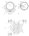
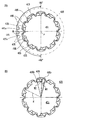
- FIG. 8 (A) is an enlarged view of FIG. 2 (b). That is, FIG. 8A is a diagram schematically showing a state in which a part of the fifth speed drive gear 425 and the first slider 451 are meshed with each other.
- reference numeral 425a is a tooth portion of the fifth-speed drive gear 425
- reference numeral 445a is a tooth portion of the fifth-speed driven gear 445.
- FIG. 8A only a part of the tooth portion in the fifth speed driving gear 425 and the fifth speed driven gear 445 is illustrated, and in the other parts, the outermost periphery of the gear is a circle of a two-dot chain line. It is shown in the figure.
- the circumference of the fifth-speed drive gear 425 is based on the line connecting the mesh point M of the fifth-speed drive gear 425 and the fifth-speed driven gear 445 and the axis center P of the drive shaft 41.
- a plurality of (four in the example in the figure) five-speed dog convex portions 465 A plurality of (four in the illustrated example) five-speed dog recesses 475 mesh with each other.
- the stress generated during the engagement can be efficiently dispersed.
- position of the 5-speed drive gear 425 is stabilized by making the number which the 5-speed dog convex part 465 and the 5-speed dog recessed part 475 mesh into 4 or more. Therefore, variation in sound per dog can also be suppressed.
- one of the circumferential direction and the other corresponds to the rotational direction of the fifth-speed drive gear 425.
- the number of meshing of the 6-speed dog convex portion 466 and the 6-speed dog convex portion 476 within the above range into 4 or more the stress generated during the meshing can be efficiently dispersed. Further, by setting the number of meshes of the six-speed dog convex portion 466 and the six-speed dog concave portion 476 to four or more, the posture of the six-speed drive gear 426 is stabilized. Therefore, variation in sound per dog can also be suppressed.
- first-speed dog convex portions 461 of the second slider 452 and first-speed dog concave portions 471 of the first-speed driven gear 441 By increasing the number of first-speed dog convex portions 461 of the second slider 452 and first-speed dog concave portions 471 of the first-speed driven gear 441 to some extent, the first-speed dog convex portions 461 and the first-speed dog concave portions 471 are engaged with each other. The accompanying stress is dispersed. Therefore, the sound per dog can be further suppressed. Further, the posture of the first-speed driven gear 441 is stabilized by increasing the number of the first-speed dog convex portions 461 and the first-speed dog concave portions 471 to some extent. Therefore, variation in sound per dog can also be suppressed.
- a line connecting the meshing point of the first-speed driving gear 421 and the first-speed driven gear 441 and the axis center of the driven shaft 43 is used as a reference.
- a plurality of (four in the example in the figure) within the range of +90 degrees (90 degrees in one circumferential direction) and -90 degrees (90 degrees in the other circumferential direction) in the circumferential direction of the first-speed driven gear 441 The first-speed dog convex portions 461 and a plurality (four in the illustrated example) of first-speed dog concave portions 471 are engaged with each other. Thereby, the above-mentioned effect is acquired.
- the number of meshes of the first-speed dog convex portions 461 and the first-speed dog concave portions 471 within the above range into four or more the stress generated when the meshes can be efficiently dispersed. Further, by setting the number of meshes of the first-speed dog convex portion 461 and the first-speed dog concave portion 471 to four or more, the posture of the first-speed driven gear 441 is stabilized. Therefore, variation in sound per dog can also be suppressed.
- one of the circumferential direction and the other corresponds to the rotational direction of the first-speed driven gear 441.
- the third-speed dog convex portions 463 of the second slider 452 and the third-speed dog concave portions 473 of the third-speed driven gear 443 are increased to some extent, the third-speed dog convex portions 463 and the third-speed dog concave portions 473 are engaged with each other. The stress generated in is dispersed. Therefore, the sound per dog can be further suppressed. Further, the posture of the third-speed driven gear 443 is stabilized by increasing the number of the third-speed dog convex portions 463 and the third-speed dog concave portions 473 to some extent. Therefore, variation in sound per dog can also be suppressed.
- the third-speed driven gear 443 has a plurality of (four in the example in the figure) within the range of +90 degrees (90 degrees in one circumferential direction) and -90 degrees (90 degrees in the other circumferential direction) in the circumferential direction.
- the three-speed dog convex portion 463 and a plurality (four in the illustrated example) of three-speed dog concave portions 473 are engaged with each other. Thereby, the above-mentioned effect is acquired.
- the number of meshing between the third-speed dog convex portion 463 and the third-speed dog concave portion 473 within the above range into four or more the stress generated when the meshing can be efficiently dispersed. Further, by setting the number of meshes of the third-speed dog convex portion 463 and the third-speed dog concave portion 473 to four or more, the posture of the third-speed driven gear 443 is stabilized. Therefore, variation in sound per dog can also be suppressed.
- the second-speed dog convex portions 462 of the third slider 453 and the second-speed dog concave portions 472 of the second-speed driven gear 442 are increased to some extent, the second-speed dog convex portions 462 and the second-speed dog concave portions 472 are engaged with each other. The stress generated in is dispersed. Therefore, the sound per dog can be further suppressed. Further, by increasing the number of second-speed dog convex portions 462 and second-speed dog concave portions 472 to some extent, the posture of the second-speed driven gear 442 is stabilized. Therefore, variation in sound per dog can also be suppressed.
- a line connecting the meshing point of the second-speed drive gear 422 and the second-speed driven gear 442 and the axis center of the driven shaft 43 is used as a reference.
- a plurality of (four in the example in the figure) within the range of +90 degrees (90 degrees in one circumferential direction) and -90 degrees (90 degrees in the other circumferential direction) of the second speed driven gear 442 The two-speed dog convex portions 462 and a plurality of (four in the illustrated example) second-speed dog concave portions 472 are engaged with each other. Thereby, the above-mentioned effect is acquired.
- the stress generated during the meshing can be efficiently dispersed. Further, by setting the number of engagements of the second-speed dog convex portion 462 and the second-speed dog concave portion 472 to four or more, the posture of the second-speed driven gear 442 is stabilized. Therefore, variation in sound per dog can also be suppressed.
- a line connecting the meshing point of the fourth speed driving gear 424 and the fourth speed driven gear 444 and the axis center of the driven shaft 43 is used as a reference.
- Four-speed dog convex portions 464 and a plurality of (four in the illustrated example) four-speed dog concave portions 474 mesh with each other.
- the number of meshes of the four-speed dog convex portions 464 and the four-speed dog concave portions 474 within the above range into four or more the stress generated during the meshing can be efficiently dispersed. Further, by setting the number of meshes of the four-speed dog convex portion 464 and the four-speed dog concave portion 474 to four or more, the posture of the four-speed driven gear 444 is stabilized. Therefore, variation in sound per dog can also be suppressed.
- one of the circumferential direction and the other corresponds to the rotational direction of the fourth-speed driven gear 444.
- the plurality of five-speed dog convex portions 465 include five-speed dog convex portions 465 a (an example of dog convex portions included in the first group) and five-speed dog convex portions 465 b (first An example of a dog convex portion included in two groups).
- the length of the fifth speed dog convex portion 465a along the axial direction of the drive shaft 41 is longer than the length of the fifth speed dog convex portion 465b along the axial direction.
- the fifth speed dog convex portion 465a (an example of the preceding approach portion) is one of the plurality of five-speed dog concave portions 475. Enter.
- the width W1 of each five-speed dog convex portion 465a in the circumferential direction of the fifth-speed drive gear 425 is equal to the width W2 of each five-speed dog concave portion 475 in the circumferential direction of the fifth-speed drive gear 425. Less than half.
- the width W1 of each five-speed dog convex portion 465a in the circumferential direction of the fifth-speed drive gear 425 and the width W2 of each five-speed dog concave portion 475 in the circumferential direction are respectively a plurality of five-speed dog convex portions 465.
- it means a dimension along the circumferential direction at a meshing position where a plurality of five-speed dog recesses 475 mesh.
- the meshing position is a position having a radius R from the center of the drive shaft 41, and is a position indicated by the circumference of the alternate long and short dash line in FIG.
- the tip of the five-speed dog convex portion 465 in the axial direction of the drive shaft 41 does not collide with the side surface of the fifth-speed drive gear 425 that axially opposes the five-speed dog convex portion 465.
- the probability of entering the recess 475 increases. Thereby, generation
- the plurality of six-speed dog convex portions 466 include a six-speed dog convex portion 466a and a six-speed dog convex portion 466b.
- the length of the six-speed dog convex portion 466a along the axial direction of the drive shaft 41 is longer than the length of the six-speed dog convex portion 466b along the axial direction. Therefore, when the plurality of six-speed dog convex portions 466 are engaged with the plurality of six-speed dog convex portions 476, first, the six-speed dog convex portion 466a (an example of the preceding approach portion) is one of the plurality of six-speed dog concave portions 476. Enter.
- each six-speed dog convex portion 466a in the circumferential direction of the six-speed drive gear 426 is different from the width in the circumferential direction of the six-speed drive gear 426. It is less than half the width of the six-speed dog recess 476.
- each of the six-speed dog convex portions 466a in the circumferential direction of the six-speed drive gear 426 and the width of each of the six-speed dog concave portions 476 in the circumferential direction are respectively defined as a plurality of six-speed dog convex portions 466 and a plurality of This means the dimension along the circumferential direction at the meshing position (corresponding to the position indicated by the circumference of the alternate long and short dash line in FIG. 8B) where the six-speed dog recess 476 meshes.
- the tip of the six-speed dog convex portion 466 in the axial direction of the drive shaft 41 does not collide with the side surface of the six-speed drive gear 426 facing the six-speed dog convex portion 466 in the axial direction.
- the probability of entering the dog recess 476 increases. Thereby, generation
- the plurality of first-speed dog convex portions 461 provided on the second slider 452 include a first-speed dog convex portion 461 having a relatively long length along the axial direction of the driven shaft 43; And a relatively short first-speed dog convex portion 461. Therefore, when the plurality of first-speed dog convex portions 461 mesh with the plurality of first-speed dog concave portions 471, first, the relatively long first-speed dog convex portion 461 (an example of the preceding approach portion) is the plurality of first-speed dog concave portions. Enter one of 471.
- the width in the circumferential direction of the first-speed driven gear 441 of each relatively fast first-speed dog convex portion 461 is each first-speed dog concave portion. It is less than half the width in the circumferential direction of the one-speed driven gear 441 of 471.
- the relatively long width of the first-speed driven gear 441 of each first-speed dog convex portion 461 and the width of each first-speed dog concave portion 471 in the circumferential direction are a plurality of first-speed dog convex portions. This means a dimension along the circumferential direction at a meshing position (corresponding to a position indicated by a one-dot chain line in FIG. 8B) where 461 and a plurality of first-speed dog recesses 471 mesh.
- the tip of the first-speed dog convex portion 461 in the axial direction of the driven shaft 43 does not collide with the side surface of the first-speed driven gear 441 facing the first-speed dog convex portion 461 in the axial direction.
- the probability of entering the first-speed dog recess 471 is increased. Thereby, generation
- the plurality of three-speed dog convex portions 463 provided on the second slider 452 are configured such that the length along the axial direction of the driven shaft 43 is relatively long and the relatively short three-speed dog convex portions 463. Part 463. Therefore, when the plurality of third-speed dog convex portions 463 are engaged with the plurality of third-speed dog concave portions 473, first, the relatively long third-speed dog convex portion 463 (an example of the second preceding approach portion) is provided with the plurality of three-speed dog convex portions 463. It enters one of the recesses 473.
- the width of the relatively long three-speed dog convex portion 463 in the circumferential direction of the three-speed driven gear 443 is the same as that of each three-speed dog concave portion. It is less than half the width in the circumferential direction of the 473 third-speed driven gear 443.
- each third-speed dog convex portion 463 in the circumferential direction of the third-speed driven gear 443 and the width of each third-speed dog concave portion 473 in the circumferential direction are a plurality of third-speed dog convex portions. This means a dimension along the circumferential direction at a meshing position (corresponding to a position indicated by a dashed line in FIG. 8B) where 463 and a plurality of third-speed dog recesses 473 mesh.
- the tip of the third-speed dog convex portion 463 in the axial direction of the driven shaft 43 does not collide with the side surface of the third-speed driven gear 443 that faces the third-speed dog convex portion 463 in the axial direction.
- the probability of entering the third speed dog recess 473 increases. Thereby, generation
- the plurality of second-speed dog convex portions 462 provided on the third slider 453 include a two-speed dog convex portion 462 having a relatively long length along the axial direction of the driven shaft 43 and a relatively short second-speed dog convex portion. Part 462. Therefore, when the plurality of second-speed dog convex portions 462 are engaged with the plurality of second-speed dog concave portions 472, first, the relatively long second-speed dog convex portion 462 (an example of the preceding approach portion) is the plurality of second-speed dog concave portions 472. Enter one of the.
- the width of the relatively long second-speed dog convex portion 462 in the circumferential direction of the second-speed driven gear 442 is the same as that of each second-speed dog concave portion. It is less than half of the width in the circumferential direction of the second-speed driven gear 442 of 472.
- each second-speed dog convex portion 462 in the circumferential direction of the second-speed driven gear 442 and the width of each second-speed dog concave portion 472 in the circumferential direction are a plurality of second-speed dog convex portions. This means a dimension along the circumferential direction at a meshing position (corresponding to a position indicated by a one-dot chain line in FIG. 8B) where 462 and a plurality of second-speed dog recesses 472 mesh.
- the tip of the second-speed dog convex portion 462 in the axial direction of the driven shaft 43 does not collide with the side surface of the second-speed driven gear 442 facing the second-speed dog convex portion 462 in the axial direction.
- the probability of entering the second-speed dog recess 472 increases. Thereby, generation
- the plurality of four-speed dog protrusions 464 provided on the third slider 453 are composed of a four-speed dog protrusion 464 having a relatively long length along the axial direction of the driven shaft 43 and a four-speed dog protrusion having a relatively short length. Part 464. Therefore, when the plurality of four-speed dog convex portions 464 mesh with the plurality of four-speed dog concave portions 474, first, the relatively long four-speed dog convex portion 464 (an example of the second preceding approach portion) is provided with the plurality of four-speed dog convex portions 464. Enter one of the recesses 474.
- the width in the circumferential direction of the four-speed driven gear 444 of each relatively long four-speed dog convex portion 464 is equal to each four-speed dog concave portion. It is less than half of the circumferential width of the 474 fourth-speed driven gear 444.
- each four-speed dog convex portion 464 in the circumferential direction of the four-speed driven gear 444 and the width of each four-speed dog concave portion 474 in the circumferential direction are a plurality of four-speed dog convex portions. It means a dimension along the circumferential direction at a meshing position (corresponding to a position indicated by a one-dot chain line in FIG. 8B) where 464 and a plurality of four-speed dog recesses 474 mesh.
- the tip of the fourth speed dog convex portion 464 in the axial direction of the driven shaft 43 does not collide with the side surface of the fourth speed driven gear 444 facing the fourth speed dog convex portion 464 in the axial direction.
- the probability of entering the four-speed dog recess 474 is increased. Thereby, generation
- the pair of the fifth speed driving gear 425 and the fifth speed driven gear 445 and the pair of the sixth speed driving gear 426 and the sixth speed driven gear 446 are A pair of helical gears.
- the helical gear can reduce the tooth thickness (the width of the gear along the axial direction) compared to a spur gear or the like. Therefore, the pair of the fifth speed driving gear 425 and the fifth speed driven gear 445 and the pair of the sixth speed driving gear 426 and the sixth speed driven gear 446 that are respectively meshed with the first slider 451 can be thinned. Therefore, the moment of inertia of the fifth and sixth gear groups can be further reduced. Thereby, the sound per dog can be further suppressed.
- the pair of the fifth speed driving gear 425 and the fifth speed driven gear 445 is a pair of helical gears.
- the pair of the first-speed drive gear 421 and the first-speed driven gear 441 and the pair of the third-speed drive gear 423 and the third-speed driven gear 443 that mesh with the second slider 452 can be made thinner. Therefore, the moment of inertia of the first and third gear groups can be further reduced. Thereby, the sound per dog can be further suppressed.
- the pair of the second speed drive gear 422 and the second speed driven gear 442 and the pair of the fourth speed drive gear 424 and the fourth speed driven gear 444 are a pair of helical gears.
- the pair of the second speed driving gear 422 and the second speed driven gear 442 and the pair of the fourth speed driving gear 424 and the fourth speed driven gear 444 that mesh with the third slider 453 can be thinned. Therefore, the moment of inertia of the second gear group and the fourth gear group can be further reduced. Thereby, the sound per dog can be further suppressed.
- the five-speed dog convex portion 465 and the six-speed dog convex portion 466 are provided on the first slider 451.
- the first slider 451 is provided with the fifth speed dog recess 475 and the sixth speed dog recess 476 in the direction orthogonal to the axial direction (the radial direction of the fifth speed drive gear 425 and the sixth speed drive gear 426).
- the size of the first slider 451 can be reduced. Thereby, the mass and radius of the first slider 451 are further reduced. Therefore, the moment of inertia of the first slider 451 can be reduced. Therefore, the sound per dog can be further suppressed.
- the second slider 452 is provided with a first-speed dog convex portion 461 and a third-speed dog convex portion 463, although not shown.
- the direction orthogonal to the axial direction (the first-speed driven gear 441 and the third-speed driven gear).
- the dimension of the second slider 452 in the radial direction of 443 can be reduced.
- the mass and radius of the second slider 452 are further reduced. Therefore, the moment of inertia of the second slider 452 can be reduced. Therefore, the sound per dog can be further suppressed.
- the third slider 453 is provided with a second speed dog convex portion 462 and a fourth speed dog convex portion 464.
- the direction orthogonal to the axial direction (the second-speed driven gear 442 and the fourth-speed driven gear).
- the dimension of the third slider 453 along the radial direction of 444 can be reduced. Thereby, the mass and radius of the third slider 453 are further reduced. Therefore, the moment of inertia of the third slider 453 can be reduced. Therefore, the sound per dog can be further suppressed.
- the vehicle 1 includes the switch 7 and the electric actuator 9.
- the switch 7 is operated by the driver.
- the electric actuator 9 rotates the shift drum 48 of the transmission 40 according to the operation of the switch 7 by the driver.
- the rotation angle and the rotation timing of the shift drum 48 can be accurately controlled by the electric actuator 9.
- the rotational phases of both can be easily synchronized, and the six-speed dog convex portion 466 and the six-speed dog concave portion 476.
- the rotational phases of the two can be easily synchronized. Therefore, generation
- the number of the five-speed dog convex portions 465a (an example of the dog convex portions included in the first group) having a relatively long length along the axial direction of the drive shaft 41 is the same as the direction.
- the number of the fifth speed dog convex portions 465b (an example of the dog convex portions included in the second group) having a relatively short length is equal.
- the number of the plurality of fifth speed dog convex portions 465a, the number of the plurality of fifth speed dog convex portions 465b, and the number of the plurality of fifth speed dog convex portions 475 are equal.
- the number of the plurality of fifth speed dog convex portions 465b may be N times the number of the plurality of fifth speed dog concave portions 475 (N is an integer of 1 or more).
- one five-speed dog convex portion 465a and one five-speed dog convex portion 465b mesh with each five-speed dog concave portion 475.
- N 2
- one five-speed dog convex portion 465a for each five-speed dog concave portion 475 Two five-speed dog convex portions 465b enter.
- one five-speed dog convex portion 465a an example of a dog convex portion included in the first group
- two five-speed dog convex portions 465b an example of a dog convex portion included in the second group.
- the fifth-speed drive gear 425 is provided so as to be alternately arranged in the circumferential direction. Also in this example, when the plurality of five-speed dog convex portions 465 mesh with the plurality of five-speed dog concave portions 475, first, the fifth speed dog convex portion 465a enters one of the plurality of five-speed dog concave portions 475.
- the 5-speed dog convex portion 465a enters the 5-speed dog concave portion 475. Thereafter, one of two five-speed dog protrusions 465b adjacent to the five-speed dog protrusion 465a in the circumferential direction of the five-speed drive gear 425 is five according to the rotation direction of the first slider 451 with respect to the fifth speed drive gear 425. Enter the fast dog recess 475. Thereby, the 5-speed dog convex part 465 and the 5-speed dog concave part 475 mesh.
- the meshing operation of the plurality of fifth-speed dog convex portions 465 and the plurality of fifth-speed dog concave portions 475 can be suppressed from varying depending on the rotation direction of the first slider 451 with respect to the fifth-speed drive gear 425. . Therefore, it is possible to further suppress the driver's uncomfortable feeling caused by the sound per dog while suppressing the sound per dog.
- the variation in the meshing operation means that the timing at which the dog convex part and the dog concave part mesh, the position at which the dog convex part, etc. vary.
- the number of the plurality of six-speed dog convex portions 466a (an example of the dog convex portions included in the first group) having a relatively long length along the axial direction of the drive shaft 41 and the axial direction
- the number of the six-speed dog convex portions 466b (an example of the dog convex portions included in the second group) having a relatively short length along the line is equal.
- the number of the plurality of six-speed dog convex portions 466a, the number of the plurality of six-speed dog convex portions 466b, and the number of the plurality of six-speed dog concave portions 476 are equal.
- the number of the plurality of six-speed dog convex portions 466b may be N times the number of the plurality of six-speed dog concave portions 476 (N is an integer of 1 or more).
- one six-speed dog convex portion 466a and one six-speed dog convex portion 466b mesh with each six-speed dog concave portion 476.
- N 2
- one six-speed dog convex portion 466a and two Six six-speed dog convex portions 466b enter.
- one six-speed dog convex portion 466a (an example of a dog convex portion included in the first group) and two six-speed dog convex portions 466b (an example of a dog convex portion included in the second group)
- the six-speed drive gears 426 are arranged alternately in the circumferential direction. Also in this example, when the plurality of six-speed dog convex portions 466 are engaged with the plurality of six-speed dog convex portions 476, the six-speed dog convex portions 466a first enter one of the plurality of six-speed dog concave portions 476.
- the six-speed dog convex portion 466a enters the six-speed dog concave portion 476. Thereafter, one of the two six-speed dog convex portions 466b adjacent to the six-speed dog convex portion 466a in the circumferential direction of the six-speed drive gear 426 depends on the rotation direction of the first slider 451 with respect to the six-speed drive gear 426. Enter the fast dog recess 476. Thereby, the 6-speed dog convex part 466 and the 6-speed dog concave part 476 mesh.
- the meshing operation of the plurality of six-speed dog convex portions 466 and the plurality of six-speed dog concave portions 476 can be suppressed from varying depending on the rotation direction of the first slider 451 with respect to the six-speed drive gear 426. . Therefore, it is possible to further suppress the driver's uncomfortable feeling caused by the sound per dog while suppressing the sound per dog.
- the number of first-speed dog convex portions 461 (an example of dog convex portions included in the first group) having a relatively long length along the axial direction of the driven shaft 43 and the same direction.
- the number of first-speed dog convex portions 461 (an example of dog convex portions included in the second group) having a relatively short length along the line is equal.
- the number of relatively long first-speed dog convex portions 461, the number of relatively short first-speed dog convex portions 461, and the number of multiple first-speed dog concave portions 471 are equal.
- the number of relatively short first-speed dog convex portions 461 may be N times the number of the plurality of first-speed dog concave portions 471 (N is an integer of 1 or more).
- one relatively fast first-speed dog convex portion 461 and one relatively short first-speed dog convex portion are provided for each first-speed dog concave portion 471.
- the part 461 is engaged.
- first speed dog convex portion 461 an example of a dog convex portion included in the first group
- two relatively short first speed dog concave portions 471 a dog included in the second group
- An example of a convex portion is provided alternately in the circumferential direction of the first-speed driven gear 441.
- the relatively long first-speed dog convex portion 461 enters one of the plurality of first-speed dog concave portions 471. To do.
- the relatively long first-speed dog convex portion 461 enters the first-speed dog concave portion 471. Thereafter, two relatively short ones adjacent to the relatively long first-speed dog convex portion 461 in the circumferential direction of the first-speed driven gear 441 according to the rotation direction of the second slider 452 with respect to the first-speed driven gear 441.
- One of the fast dog convex portions 461 enters the first speed dog concave portion 471. Thereby, the 1st-speed dog convex part 461 and the 1st-speed dog convex part 471 mesh.
- the meshing operation of the plurality of first-speed dog convex portions 461 and the plurality of first-speed dog concave portions 471 is prevented from varying depending on the rotation direction of the second slider 452 relative to the first-speed driven gear 441. it can. Therefore, it is possible to further suppress the driver's uncomfortable feeling caused by the sound per dog while suppressing the sound per dog.
- the number of a plurality of three-speed dog convex portions 463 (an example of a dog convex portion included in the first group) having a relatively long length along the axial direction of the driven shaft 43, and the axis
- the number of the third speed dog convex portions 463 (an example of the dog convex portions included in the second group) having a relatively short length along the direction is equal.
- the number of relatively long three-speed dog convex portions 463 is equal to the number of relatively short plurality of third-speed dog convex portions 463 and the number of multiple three-speed dog concave portions 473.
- the number of relatively short three-speed dog convex portions 463 may be N times the number of the plurality of third-speed dog concave portions 473 (N is an integer of 1 or more).
- one relatively long three-speed dog convex portion 463 and one relatively short three-speed dog convex portion are provided for each three-speed dog concave portion 473.
- the portion 463 is engaged.
- one relatively smaller number of the three-speed dog concave portions 473 is provided.
- a long three-speed dog convex part 463 and two relatively short three-speed dog concave parts 473 enter.
- one relatively long three-speed dog convex portion 463 (an example of a dog convex portion included in the first group) and two relatively short three-speed dog concave portions 473 (a dog included in the second group).
- An example of a convex portion is provided so as to be alternately arranged in the circumferential direction of the third-speed driven gear 443.
- the relatively long third-speed dog convex portion 463 first enters one of the plurality of third-speed dog concave portions 473. To do.
- the relatively long third-speed dog convex portion 463 enters the third-speed dog concave portion 473. Thereafter, depending on the rotation direction of the second slider 452 relative to the third-speed driven gear 443, two relatively short three adjacent to the relatively long third-speed dog convex portion 463 in the circumferential direction of the third-speed driven gear 443.
- One of the fast dog protrusions 463 enters the third speed dog recess 473. Thereby, the 3rd speed dog convex part 463 and the 3rd speed dog convex part 473 mesh.
- the number of the second speed dog convex portions 462 (an example of the dog convex portions included in the first group) having a relatively long length along the axial direction of the driven shaft 43 and the same direction.
- the number of second-speed dog convex portions 462 (an example of dog convex portions included in the second group) that are relatively short along the length is equal.
- the number of relatively long two-speed dog convex portions 462, the number of relatively short plural second-speed dog convex portions 462, and the number of plural second-speed dog concave portions 472 are equal.
- the number of relatively short two-speed dog convex portions 462 may be N times the number of the plurality of second-speed dog concave portions 472 (N is an integer of 1 or more).
- one relatively long two-speed dog convex portion 462 and one relatively short two-speed dog convex portion are provided for each two-speed dog concave portion 472. Part 462 is engaged.
- N the number of the plurality of second-speed dog concave portions 472
- one relatively long two-speed dog convex portion 462 (an example of a dog convex portion included in the first group) and two relatively short two-speed dog concave portions 472 (a dog included in the second group). (An example of a convex portion) are provided alternately in the circumferential direction of the second-speed driven gear 442. Also in this example, when the plurality of second-speed dog convex portions 462 mesh with the plurality of second-speed dog concave portions 472, first, the relatively long second-speed dog convex portion 462 enters one of the plurality of second-speed dog concave portions 472. To do.
- the relatively long second-speed dog convex portion 462 enters the second-speed dog concave portion 472. Thereafter, the two relatively short second gears 462 adjacent to the two-speed dog convex portion 462 that is relatively long in the circumferential direction of the second-speed driven gear 442 according to the rotation direction of the third slider 453 with respect to the second-speed driven gear 442.
- One of the fast dog protrusions 462 enters the second speed dog recess 472. Thereby, the 2nd speed dog convex part 462 and the 2nd speed dog recessed part 472 mesh.
- the number of the four-speed dog convex portions 464 (an example of the dog convex portions included in the first group) having a relatively long length along the axial direction of the driven shaft 43 and the same direction.
- the number of the fourth speed dog convex portions 464 (an example of the dog convex portions included in the second group) that are relatively short along the length is equal.
- the number of relatively long four-speed dog convex portions 464, the number of relatively short plural fourth-speed dog convex portions 464, and the number of plural four-speed dog concave portions 474 are equal.
- the number of the plurality of relatively short four-speed dog convex portions 464 may be N times the number of the plurality of four-speed dog concave portions 474 (N is an integer of 1 or more).
- one relatively long four-speed dog convex portion 464 and one relatively short four-speed dog convex portion are provided for each four-speed dog concave portion 474. Part 464 is engaged.
- N the number of the plurality of four-speed dog concave portions 474
- one relatively long four-speed dog convex portion 464 (an example of a dog convex portion included in the first group) and two relatively short four-speed dog concave portions 474 (a dog included in the second group).
- An example of a convex portion is provided alternately in the circumferential direction of the fourth-speed driven gear 444.
- the relatively long four-speed dog convex portion 464 enters one of the plurality of four-speed dog concave portions 474. To do.
- the relatively long four-speed dog convex portion 464 enters the four-speed dog concave portion 474. Thereafter, depending on the rotation direction of the third slider 453 relative to the fourth-speed driven gear 444, two relatively short four adjacent to the four-speed dog convex portion 464 that is relatively long in the circumferential direction of the four-speed driven gear 444.
- One of the fast dog convex portions 464 enters the fast dog concave portion 474. Thereby, the 4-speed dog convex part 464 and the 4-speed dog concave part 474 mesh.
- the vehicle 1 may further include an auxiliary transmission mechanism 11.
- the subtransmission mechanism 11 is provided either upstream of the drive shaft 41 or downstream of the driven shaft 43 with respect to the transmission direction of the power generated by the internal combustion engine 3.
- the subtransmission mechanism 11 has, for example, two pairs of drive gears and driven gears having different speed ratios.
- the subtransmission mechanism 11 is a mechanism that substantially doubles the number of shift stages in the vehicle 1 with respect to the number of shift stages of the transmission 4.
- the operation of the electric actuator 9 that rotates the shift drum 48 is controlled by the switch 7 provided on the handle 6.
- the switch 7 may not be disposed on the handle 6.
- the switch 7 may not be operated by the driver's hand.
- the switch 7 may be disposed near the foot pedal of the vehicle 1.
- the switch 7 may be operated by a driver's foot.
- the operation of the electric actuator 9 that rotates the shift drum 48 may not be controlled by the operation of the switch 7 by the driver.
- the control unit 8 may automatically control the operation of the electric actuator 9 according to the traveling state of the vehicle 1 detected by a vehicle sensor (not shown).
- the speed change operation of the transmission 4 can be automatically executed without any driver's operation.
- the automatic transmission operation is often performed at a timing different from the driver's intention. Therefore, there is a tendency for the driver to be aware of the sound per dog.
- the driver can be aware of the sound per dog.
- not only the sound per dog but also the variation of the sound per dog can be suppressed. Thereby, even in a configuration in which automatic gear shifting is performed, the driver's uncomfortable feeling can be suppressed.
- the transmission 4 has a configuration capable of six-speed transmission.
- the number of gears that can be shifted can be appropriately determined according to the specifications of the vehicle 1.
- the number of pairs of driving gears and driven gears included in the transmission 4 can be determined as appropriate according to the number of necessary steps, along with whether or not the above-described auxiliary transmission mechanism 11 is employed in the vehicle 1.
- each drive gear can rotate with respect to the drive shaft 41 is not limited to the example shown as the above embodiment, and can be determined as appropriate according to the specifications of the transmission 4.
- the driven gear that meshes with the drive gear is not allowed to rotate with respect to the driven shaft 43.
- the driven gear that meshes with the drive gear can rotate with respect to the driven shaft 43.
- the slider is arranged side by side in the axial direction with respect to a gear that can rotate relative to the drive shaft 41 or the driven shaft 43 among the gears arranged on the drive shaft 41 or the driven shaft 43.
- the number of sliders included in the transmission 4 can be appropriately determined according to the number of pairs of driving gears and driven gears. At this time, it can be appropriately determined according to the specification of the transmission 4 whether the slider is disposed between the pair of adjacent drive gears and the pair of driven gears.
- the relationship between the number of dog convex portions and the number of dog concave portions described with reference to FIG. 8 only needs to be established by the dog convex portions and the dog concave portions in at least one slider of the transmission device 4.
- At least one pair may be a pair of spur gears.
- both the fifth speed dog convex portion 465 and the sixth speed dog convex portion 466 are provided on the first slider 451.
- the first slider 451 may be provided with at least one of the 5-speed dog recess and the 6-speed dog recess.
- the fifth speed dog recess is provided on the first slider 451
- the fifth speed dog protrusion is provided on the fifth speed drive gear 425.
- the six-speed dog recess is provided on the first slider 451
- the six-speed dog protrusion is provided on the six-speed drive gear 426.
- both the first speed dog convex portion 461 and the third speed dog convex portion 463 are provided on the second slider 452.
- a configuration in which at least one of the first-speed dog recess and the third-speed dog recess is provided in the second slider 452 may be employed.
- the first-speed dog recess is provided on the second slider 452
- the first-speed dog protrusion is provided on the first-speed driven gear 441.
- the third-speed dog recess is provided on the second slider 452
- the third-speed dog protrusion is provided on the third-speed driven gear 443.
- both the second speed dog convex portion 462 and the fourth speed dog convex portion 464 are provided on the third slider 453.
- the third slider 453 may be provided with at least one of the second speed dog recess and the fourth speed dog recess.
- the second-speed dog recess is provided on the third slider 453
- the second-speed dog protrusion is provided on the second-speed driven gear 442.
- the fourth-speed dog recess is provided on the third slider 453
- the fourth-speed dog protrusion is provided on the fourth-speed driven gear 444.
- first speed dog convex portion 461, the second speed dog convex portion 462, the third speed dog convex portion 463, the fourth speed dog convex portion 464, the fifth speed dog convex portion 465, and the sixth speed dog convex portion 466 are all included. However, it has a gear tooth shape when viewed from the axial direction of the drive shaft 41.
- At least one of the first speed dog convex portion 461, the second speed dog convex portion 462, the third speed dog convex portion 463, the fourth speed dog convex portion 464, the fifth speed dog convex portion 465, and the sixth speed dog convex portion 466 is: You may arrange
- At least one kind of dog convex portion of the first speed dog convex portion 461, the second speed dog convex portion 462, the third speed dog convex portion 463, the fourth speed dog convex portion 464, the fifth speed dog convex portion 465, and the sixth speed dog convex portion 466 is: A protrusion extending toward the driving gear or the driven gear meshing with the dog convex portion may be used.
- the number and shape of at least one of the first-speed dog recess 471, the second-speed dog recess 472, the third-speed dog recess 473, the four-speed dog recess 474, the fifth-speed dog recess 475, and the six-speed dog recess 476 It is determined as appropriate so that it can be engaged with each other.
- FIG. 9A schematically shows a state where the first slider 451A according to the modified example configured as described above and the fifth-speed drive gear 425A according to the modified example are engaged with each other. Similarly to FIG. 8A, FIG. 9A also shows only some of the teeth of the fifth-speed driving gear 425A and the fifth-speed driven gear 445.
- the tip portion of the five-speed dog convex portion 465 a having a relatively long length along the axial direction of the drive shaft 41 and the five relatively short lengths.
- the tip of the fast dog convex portion 465b is separated in the circumferential direction of the first slider 451.
- the shape of the fifth speed dog convex portion 465A is not limited to the same configuration as that in FIG.
- FIG. 9B schematically shows a cross-sectional shape along the circumferential direction of the first slider 451A in one of the five-speed dog convex portions 465A among the plurality of five-speed dog convex portions 465A shown in FIG. FIG.
- a structure in which a relatively short fifth speed dog convex portion 465Ab and a relatively long fifth speed dog convex portion 465Aa may be connected.
- Such a configuration can be similarly applied to the first speed dog convex portion 461, the second speed dog convex portion 462, the third speed dog convex portion 463, the fourth speed dog convex portion 464, and the sixth speed dog convex portion 466. is there.
- the engagement between the dog convex portions and the dog concave portions is not limited to the case where the plurality of dog convex portions and the plurality of dog concave portions are all meshed with each other, but at least one of the plurality of dog convex portions and the plurality of dog concave portions. This includes the case where at least one of them meshes.
- the vehicle 1 includes an internal combustion engine 3 as a power source.
- a motor may be used as a power source of the vehicle 1 as long as the transmission 4 that performs the shift using the shift drum 48 is provided.
- the vehicle 1 according to the above embodiment is a motorcycle. However, if the transmission 4 that shifts using the shift drum 48 is provided, the number of front wheels 21 and rear wheels 22 provided in the vehicle 1 can be determined as appropriate.
Landscapes
- Engineering & Computer Science (AREA)
- General Engineering & Computer Science (AREA)
- Mechanical Engineering (AREA)
- Chemical & Material Sciences (AREA)
- Combustion & Propulsion (AREA)
- Transportation (AREA)
- Gear-Shifting Mechanisms (AREA)
- Mechanical Operated Clutches (AREA)
- Structure Of Transmissions (AREA)
Abstract
第一スライダ451および五速駆動歯車425が、駆動軸41上に軸方向に並んで配置されている。複数の五速ドグ凸部465が、第一スライダ451に設けられている。シフトドラム48のガイド溝481に一方の端部が位置付けられたシフトフォークの他方の端部が、第一スライダ451に接続されている。複数の五速ドグ凹部475が、五速駆動歯車425に設けられている。五速への変速時において、第一スライダ451が駆動軸上を軸方向に移動し、複数の五速ドグ凸部465と複数の五速ドグ凹部475とが噛み合う。五速駆動歯車425と五速被駆動歯車445との噛み合い点Mと駆動軸の軸中心Pとを結んだ線を基準として、五速駆動歯車425の周方向の一方に90度および他方に90度の範囲内で、複数の五速ドグ凸部465および複数の五速ドグ凹部475のうち少なくとも四つが噛み合っている。
Description
本発明は、車両に搭載される変速装置、および該変速装置を備えた車両に関する。
車両に搭載される変速装置は、軸方向に延びるとともにクラッチ機構を介して動力源(エンジンやモータなど)に接続された駆動軸と、前記軸方向に延びる被駆動軸とを備えている。前記駆動軸及び前記被駆動軸には、それぞれ、変速段の数に対応する数の歯車が設けられている。このような構成を有する変速装置では、変速段ごとに、前記駆動軸に設けられた駆動歯車と前記被駆動軸に設けられた被駆動歯車とが噛み合うことにより、歯車対を構成している。各歯車対の変速比は相違している。前記変速装置は、選択された変速段に応じて、当該変速段に対応する歯車対のみが動力を伝達する。
例えば、特許文献1に開示されている変速装置は、シフトドラム及びシフトフォークを備えている。前記シフトドラムは、シフトロッドの往復移動によって回転する。前記シフトドラムの外周面には、複数のカム溝が形成されている。前記シフトフォークは、前記シフトドラムの前記カム溝内に一端が位置付けられている。前記シフトフォークは、他端が、例えば、前記メイン軸上に配置された所定の変速ギアに接続されている。
前記所定の変速ギアは、前記メイン軸に、該メイン軸に対して軸方向に移動可能に設けられている。前記シフトドラムは、選択された変速段に応じて、回転角度が変化する。前記カム溝は、前記回転角度に応じて前記メイン軸の軸方向における位置が変化するように、前記シフトドラムの外周面に形成されている。これにより、選択された変速段に応じて、前記カム溝内に一端が位置付けられている前記シフトフォークが前記メイン軸の軸方向に移動する。よって、前記シフトフォークの他端と接続されている前記所定の変速ギアが、前記メイン軸の軸方向に移動する。
前記所定の変速ギアは、前記メイン軸に相対回転不能に設けられている。前記所定の変速ギアと噛み合う所定の被駆動ギアは、ドライブ軸に、該ドライブ軸に対して相対回転可能に設けられている。前記所定の変速ギアに対して前記メイン軸の軸方向に並ぶ駆動ギアは、前記メイン軸に相対回転可能に設けられている。前記駆動ギアと噛み合う被駆動ギアは、前記ドライブ軸に相対回転不能に設けられている。
前記所定の変速ギアは、ドグ凸部を有する。前記ドグ凸部は、前記駆動ギアに向かって延びている。前記駆動ギアには、ドグ凹部が設けられている。前記シフトドラムの回転によって、前記シフトフォークが前記メイン軸の軸方向に移動した場合、前記所定の変速ギアが前記駆動ギアに向かって前記軸方向に移動する。これにより、前記所定の変速ギアのドグ凸部と前記駆動ギアのドグ凹部とが係合する。よって、前記所定の変速ギアと同期して前記駆動ギアが回転する。したがって、該駆動ギア及び前記被駆動ギアの歯車対を介して、前記メイン軸から前記ドライブ軸に動力が伝達される。すなわち、前記所定の変速ギアが前記メイン軸の軸方向に移動することによって、変速装置の変速動作が行われる。
上述のような構成を有する変速装置では、変速動作の際に、いわゆる「ドグ当たり音」と称される音の発生が避けられない。駆動軸(メイン軸)が回転している状態では、ドグ凸部が設けられているとともに前記駆動軸と一体で回転する一方の駆動歯車(所定の変速ギア)と、ドグ凹部が設けられているとともに前記駆動軸と相対回転する他方の駆動歯車(駆動ギア)とは、相対回転している。ドグ当たり音は、前記一方の駆動歯車の回転と前記他方の駆動歯車の回転とが同期する際に生ずる音である。
具体的には、前記一方の駆動歯車が前記他方の駆動歯車に接近する際において、前記ドグ凸部の先端が前記他方の駆動歯車の側面(前記ドグ凹部が設けられていない部分)に衝突した場合(歯車の軸方向に係る衝突)に、ドグ当たり音が発生する。また、上述のような衝突の有無によらず、ドグ凸部の側面とドグ凹部の側面とが衝突する場合(歯車の周方向の位置での衝突)にも、ドグ当たり音が発生する。
加えて、前記変速装置では、同じ変速動作であっても、ドグ当たり音は常に一定ではない。そのため、運転者の違和感を増長させる。これは、シフトフォークの一端とシフトドラムのガイド溝(カム溝)の側面との間、およびシフトフォークの他端と該他端が接続される前記駆動歯車の部分との間に、クリアランスが存在していることに起因する。このようなクリアランスの存在によって、シフトフォークは傾きやすく、駆動歯車の軸方向の変位が一定になりにくいからである。
すなわち、上述のようにシフトフォークが傾くことにより、該シフトフォークによって前記軸方向に移動する前記一方の駆動歯車が、前記他方の駆動歯車に対して傾く。よって、前記一方の駆動歯車に設けられたドグ凸部も、前記他方の駆動歯車に設けられたドグ凹部に対して傾く。このような前記一方の駆動歯車に設けられたドグ凸部の傾きにより、該ドグ凸部と、前記他方の駆動歯車に設けられたドグ凹部との接触の状態が変わる。そのため、ドグ当たり音が一定になりにくい。
以上より、本発明では、変速装置において、ドグ当たり音を抑制しつつ、ドグ当たり音に起因する運転者の違和感も低減可能な構成を得る。
本発明者は、鋭意検討の結果、衝突に関与する部材の慣性モーメントを低減することにより、ドグ当たり音を抑制できると考えた。衝突に関与する部材の慣性モーメントが小さければ、ドグ当たり音に直接関与する衝突エネルギーを低減できるからである。
そこで、本発明者は、まず、上述した一方の駆動歯車からドグ凸部を分離することを考えた。すなわち、本発明者は、一対の駆動歯車の間に、駆動軸の軸方向に移動可能なスライダを配置するとともに、該スライダがドグ凸部を備える変速装置の構成を考えた。シフトフォークは、他端を前記スライダに接続する。これにより、前記一方の駆動歯車を前記駆動軸の軸方向に移動させる場合と比べて、ドグ凸部が設けられた部材(スライダ)の質量及び半径を小さくすることができる。その結果、前記部材の慣性モーメントを低減できる。したがって、ドグ当たり音を抑制できる。
上述のように前記スライダの半径を比較的小さくすることにより、前記スライダを移動させる力を、シフトフォークによって、駆動軸により近い位置で前記スライダに与えることができる。これにより、前記スライダが移動する際に、該スライダの姿勢を安定させることができる。よって、前記スライダのドグ凸部が、他方の駆動歯車に設けられたドグ凹部と接触する際のドグ当たり音のばらつきを抑制できる。
したがって、上述のように前記一方の駆動歯車とドグ凸部とを分離することにより、ドグ当たり音を抑制できるだけでなく、ドグ当たり音のばらつきに起因した運転者の違和感を低減できる。
本発明者は、さらなる検討を重ねた結果、ドグ凸部及びドグ凹部の数を増やすことにより、各ドグ凸部と各ドグ凹部とが噛み合う際に生じる応力が分散され、その結果、ドグ当たり音をより抑制できることを見出した。
スライダのドグ凸部が接触する他方の駆動歯車(遊転歯車)は、該他方の歯車が設けられた駆動軸と相対回転可能であるため、該駆動軸に対して傾く場合がある。本発明者は、特に、前記他方の駆動歯車が、被駆動軸と相対回転不能な被駆動歯車(固定歯車)と噛み合ってる場合には、その噛み合い点で前記他方の駆動歯車の傾きが大きくなることに気づいた。このように前記他方の駆動歯車が傾いている場合でも、上述のようにドグ凸部及びドグ凹部の数を増やすことにより、各ドグ凸部と各ドグ凹部とが噛み合う際に生じる応力を分散させることができる。よって、ドグ当たり音をより抑制することができる。
本発明者は、詳細な検討の結果、被駆動歯車(固定歯車)と他方の駆動歯車(遊転歯車)との噛み合い点と駆動軸の軸中心とを結ぶ線を基準として、該駆動軸の周方向の一方及び他方にそれぞれ90度の範囲内で少なくとも四つのドグ凸部とドグ凹部とが噛み合っている場合に、ドグ当たり音を抑制しつつ、ドグ当たり音に起因した運転者の違和感も低減できることを見出した。
なお、以上の説明では、駆動軸に軸方向に並んで設けられた一対の駆動歯車の間にスライダが配置されているとともに、当該スライダにドグ凸部が設けられた構成を一例として挙げた。しかしながら、被駆動軸に軸方向に並んで設けられた一対の被駆動歯車の間にスライダが配置されてもよい。この場合には、遊転歯車である被駆動歯車に対して、スライダは被駆動軸の軸方向に移動する。また、駆動歯車または被駆動歯車にドグ凸部が設けられ、スライダにドグ凹部が設けられてもよい。
また、一対の駆動歯車の間または一対の被駆動歯車の間に、スライダを配置する構成に限らず、遊転歯車である、一つの駆動歯車または被駆動歯車に対して、スライダが移動可能に配置された構成であってもよい。
本発明の一実施形態に係る変速装置は、車両に搭載される変速装置である。この変速装置は、軸方向に延びるとともにクラッチ機構を介して動力源に接続された駆動軸と、前記軸方向に延びる被駆動軸と、前記駆動軸及び前記被駆動軸のうち一方の軸に、前記軸方向に固定され且つ一体で回転可能に設けられた固定歯車と、前記駆動軸及び前記被駆動軸のうち他方の軸に、前記軸方向に固定され且つ相対回転可能に設けられ、前記固定歯車と噛み合う遊転歯車と、前記他方の軸に、前記軸方向に移動可能に且つ一体で回転可能に設けられ、前記一方の軸に設けられた歯車に対して直接、動力伝達を行わないスライダと、前記軸方向に延びる円筒状または円柱状に形成されているとともに外周面に周方向に延びるガイド溝を有し、且つ、前記軸方向に延びるドラム軸を中心として回転可能に構成されたシフトドラムと、前記シフトドラムから前記スライダに向かって延びるとともに、前記シフトドラムのガイド溝内に一方の端部が位置付けられ、前記スライダに他方の端部が接続されたシフトフォークとを備える。
前記スライダ及び前記遊転歯車の一方には、複数のドグ凸部が設けられている。前記スライダ及び前記遊転歯車の他方には、前記複数のドグ凸部の少なくとも一部と噛み合う複数のドグ凹部が設けられている。
前記スライダは、前記シフトドラムの回転に応じて前記シフトフォークが前記ガイド溝内を移動することによって、前記複数のドグ凸部の少なくとも一つと前記複数のドグ凹部の少なくとも一つとが噛み合う位置まで前記軸方向に移動可能に構成されている。
前記遊転歯車は、前記スライダの前記軸方向への移動によって前記複数のドグ凸部の少なくとも一つと前記複数のドグ凹部の少なくとも一つとが噛み合った状態で、前記スライダ及び前記他方の軸と一体で回転する。
前記複数のドグ凸部及び前記複数のドグ凹部は、前記シフトドラムの回転に応じて前記シフトフォークが前記ガイド溝内を移動することによって、前記スライダが、前記他方の軸に前記軸方向に固定された前記遊転歯車に向かって移動することにより、前記複数のドグ凸部の少なくとも一つと前記複数のドグ凹部の少なくとも一つとが噛み合った状態において、前記軸方向から見て、前記固定歯車と前記遊転歯車とが噛み合う噛み合い点と前記他方の軸における軸中心とを結ぶ線を基準として、前記他方の軸における周方向の一方及び他方にそれぞれ90度の範囲内で、少なくとも四つが噛み合う。
本発明の一実施形態に係る変速装置によれば、ドグ当たり音を抑制しつつ、ドグ当たり音に起因する運転者の違和感も低減することができる。
図1から図8を参照しつつ、一実施形態に係る車両1(車両の一例)について説明する。以下の説明に用いる各図面では、各部材を認識可能な大きさとするために縮尺を適宜変更している。以下の説明における「左」と「右」は、それぞれ、車両1に乗車した運転者から見た「左」と「右」を表している。
図1は、車両1を右方から見た場合における車両1の外観を示している。矢印Fは、車両1の前方向を示している。矢印Bは、車両1の後方向を示している。矢印Uは、車両1の上方向を示している。矢印Dは、車両1の下方向を示している。
本実施形態において、車両1は、前輪21と後輪22とを備えている自動二輪車である。車両1は、内燃機関3(動力源の一例)と変速装置4とを備えている。換言すると、変速装置4は、車両1に搭載されている。
図2は、本実施形態に係る変速装置4の構成を示している。具体的には、図2(a)は、変速装置4の構成を模式的に示している。図2(b)は、変速装置4の後述する第一スライダ451および五速駆動歯車425の構成を模式的に示している。
図3は、図2(a)を拡大して示す図である。変速装置4は、駆動軸41を備えている。車両1は、クラッチ機構5を備えている。駆動軸41は、クラッチ機構5を介して内燃機関3に接続されている。以下の説明において、駆動軸41の延びている方向を「軸方向」と定義する。
クラッチ機構5は、内燃機関3におけるクランクシャフトの回転が駆動軸41に伝達される接続状態と、前記クランクシャフトの回転が駆動軸41に伝達されない切断状態とに切り替え可能に構成されている。
変速装置4は、一速駆動歯車421、二速駆動歯車422、三速駆動歯車423、四速駆動歯車424、五速駆動歯車425、および六速駆動歯車426を備えている。一速駆動歯車421、二速駆動歯車422、三速駆動歯車423、四速駆動歯車424、五速駆動歯車425、および六速駆動歯車426は、駆動軸41上に軸方向に並んで配置されている。
変速装置4は、被駆動軸43を備えている。被駆動軸43は、軸方向に延びている。すなわち、被駆動軸43は、駆動軸41と平行に延びている。被駆動軸43は、駆動軸41の軸方向に延びている。なお、駆動軸41または被駆動軸43が軸方向に延びているとは、駆動軸41または被駆動軸43が軸方向に長い形状であることを意味する。
変速装置4は、一速被駆動歯車441、二速被駆動歯車442、三速被駆動歯車443、四速被駆動歯車444、五速被駆動歯車445、および六速被駆動歯車446を備えている。一速被駆動歯車441、二速被駆動歯車442、三速被駆動歯車443、四速被駆動歯車444、五速被駆動歯車445、および六速被駆動歯車446は、被駆動軸43上に軸方向に並んで配置されている。
一速被駆動歯車441は、一速駆動歯車421と常時噛み合っている。二速被駆動歯車442は、二速駆動歯車422と常時噛み合っている。三速被駆動歯車443は、三速駆動歯車423と常時噛み合っている。四速被駆動歯車444は、四速駆動歯車424と常時噛み合っている。五速被駆動歯車445は、五速駆動歯車425と常時噛み合っている。六速被駆動歯車446は、六速駆動歯車426と常時噛み合っている。
一速駆動歯車421は、駆動軸41に対して回転不能である。すなわち、一速駆動歯車421は、駆動軸41と一体で回転可能である。一速被駆動歯車441は、被駆動軸43と相対回転可能である。
二速駆動歯車422は、駆動軸41に対して回転不能である。すなわち、二速駆動歯車422は、駆動軸41と一体で回転可能である。二速被駆動歯車442は、被駆動軸43と相対回転可能である。
三速駆動歯車423は、駆動軸41に対して回転不能である。すなわち、三速駆動歯車423は、駆動軸41と一体で回転可能である。三速被駆動歯車443は、被駆動軸43と相対回転可能である。
四速駆動歯車424は、駆動軸41に対して回転不能である。すなわち、四速駆動歯車424は、駆動軸41と一体で回転可能である。四速被駆動歯車444は、被駆動軸43と相対回転可能である。
五速駆動歯車425は、駆動軸41と相対回転可能である。五速被駆動歯車445は、被駆動軸43に対して回転不能である。すなわち、五速被駆動歯車445は、被駆動軸43と一体で回転可能である。
六速駆動歯車426は、駆動軸41と相対回転可能である。六速被駆動歯車446は、被駆動軸43に対して回転不能である。すなわち、六速被駆動歯車446は、被駆動軸43と一体で回転可能である。
一速駆動歯車421、二速駆動歯車422、および五速被駆動歯車445は、固定歯車の一例である。三速駆動歯車423、四速駆動歯車424、および六速被駆動歯車446は、第二固定歯車の一例である。
一速被駆動歯車441、二速被駆動歯車442、および五速駆動歯車425は、前記固定歯車と噛み合う遊転歯車の一例である。三速被駆動歯車443、四速被駆動歯車444、および六速駆動歯車426は、前記第二固定歯車と噛み合う第二遊転歯車の一例である。
変速装置4は、第一スライダ451を備えている。第一スライダ451は、駆動軸41上において、五速駆動歯車425(第一駆動歯車の一例)と六速駆動歯車426(第二駆動歯車の一例)との間に配置されている。第一スライダ451は、駆動軸41上を軸方向に移動可能である。第一スライダ451は、駆動軸41に対して回転不能である。すなわち、第一スライダ451は、駆動軸41と一体で回転可能である。
変速装置4は、第二スライダ452を備えている。第二スライダ452は、被駆動軸43上において、一速被駆動歯車441(第一被駆動歯車の一例)と三速被駆動歯車443(第二被駆動歯車の一例)との間に配置されている。第二スライダ452は、被駆動軸43上を軸方向に移動可能である。第二スライダ452は、被駆動軸43に対して回転不能である。すなわち、第二スライダ452は、被駆動軸43と一体で回転可能である。
変速装置4は、第三スライダ453を備えている。第三スライダ453は、被駆動軸43上において、二速被駆動歯車442(第一被駆動歯車の一例)と四速被駆動歯車444(第二被駆動歯車の一例)との間に配置されている。第三スライダ453は、被駆動軸43上を軸方向に移動可能である。第三スライダ453は、被駆動軸43に対して回転不能である。すなわち、第三スライダ453は、被駆動軸43と一体で回転可能である。
第一スライダ451、第二スライダ452、および第三スライダ453は、スライダの一例である。
図4は、変速装置4のより詳細な構成を示す図である。この図4は、変速装置4を、駆動軸41及び被駆動軸43の軸方向に延びる軸線を含む断面で示す図である。
変速装置4は、五速ドグ凸部465と、五速ドグ凹部475とを備えている。五速ドグ凸部465(ドグ凸部の一例)は、第一スライダ451に設けられている。五速ドグ凹部475(ドグ凹部の一例)は、五速駆動歯車425に設けられている。
変速装置4は、六速ドグ凸部466と六速ドグ凹部476とを備えている。六速ドグ凸部466(第二ドグ凸部の一例)は、第一スライダ451に設けられている。六速ドグ凹部476(第二ドグ凹部の一例)は、六速駆動歯車426に設けられている。
図5(A)は、第一スライダ451の外観を示す斜視図である。第一スライダ451は、環状である。図5(B)は、五速駆動歯車425の外観を示す斜視図である。図6は、駆動軸41上に配置された五速駆動歯車425、六速駆動歯車426、および第一スライダ451を、被駆動軸43上に配置された五速被駆動歯車445および六速被駆動歯車446とともに示す図である。
図5(A)に示されるように、第一スライダ451には、複数の五速ドグ凸部465が、周方向に並んで設けられている。図6からも明らかなように、複数の五速ドグ凸部465は、前記軸方向に沿う長さが異なる二種類の五速ドグ凸部465a、465bを含んでいる。前記軸方向において、五速ドグ凸部465aの長さは、五速ドグ凸部465bの長さよりも長い。五速ドグ凸部465aと五速ドグ凸部465bとは、第一スライダ451に、前記周方向に交互に並ぶように設けられている。
第一スライダ451には、複数の六速ドグ凸部466が、駆動軸41を中心として周方向に並んで設けられている。図6に示されるように、複数の六速ドグ凸部466は、前記軸方向に沿う長さが異なる二種類の六速ドグ凸部466a、466bを含んでいる。前記軸方向において、六速ドグ凸部466aの長さは、六速ドグ凸部466bの長さよりも長い。六速ドグ凸部466aと六速ドグ凸部466bとは、第一スライダ451に、前記周方向に交互に並ぶように設けられている。
図5(B)に示されるように、五速駆動歯車425には、複数の五速ドグ凹部475が、五速駆動歯車425の周方向に並んで設けられている。複数の五速ドグ凹部475の数は、複数の五速ドグ凸部465の数の半分である。すなわち、各五速ドグ凹部475は、二個の五速ドグ凸部465を収容可能に構成されている。
五速駆動歯車425と同様の構成であるため図示を省略するが、六速駆動歯車426には、複数の六速ドグ凹部476が、六速駆動歯車426の周方向に並んで設けられている。複数の六速ドグ凹部476の数は、複数の六速ドグ凸部466の数の半分である。すなわち、各六速ドグ凹部476は、二個の六速ドグ凸部466を収容可能に構成されている。
図4に示されるように、変速装置4は、一速ドグ凸部461と、一速ドグ凹部471とを備えている。一速ドグ凸部461(ドグ凸部の一例)は、第二スライダ452に設けられている。一速ドグ凹部471(ドグ凹部の一例)は、一速被駆動歯車441に設けられている。
図4に示されるように、変速装置4は、三速ドグ凸部463と、三速ドグ凹部473とを備えている。三速ドグ凸部463(第二ドグ凸部の一例)は、第二スライダ452に設けられている。三速ドグ凹部473(第二ドグ凹部の一例)は、三速被駆動歯車443に設けられている。
第一スライダ451と同様の構成であるため図示を省略するが、第二スライダ452は、環状である。第二スライダ452には、複数の一速ドグ凸部461が、周方向に並んで設けられている。複数の一速ドグ凸部461は、駆動軸41の軸方向に沿う長さが異なる二種類の一速ドグ凸部を含んでいる。相対的に長い一速ドグ凸部と相対的に短い一速ドグ凸部とは、第二スライダ452に、前記周方向に交互に並ぶように設けられている。
第二スライダ452には、複数の三速ドグ凸部463が、周方向に並んで設けられている。複数の三速ドグ凸部463は、前記軸方向に沿う長さが異なる二種類の三速ドグ凸部を含んでいる。相対的に長い三速ドグ凸部と相対的に短い三速ドグ凸部とは、第二スライダ452に、前記周方向に交互に並ぶように設けられている。
五速駆動歯車425と同様の構成であるため図示を省略するが、一速被駆動歯車441には、複数の一速ドグ凹部471が、一速被駆動歯車441の周方向に並んで設けられている。複数の一速ドグ凹部471の数は、複数の一速ドグ凸部461の数の半分である。すなわち、各一速ドグ凹部471は、二個の一速ドグ凸部461を収容可能に構成されている。
三速被駆動歯車443には、複数の三速ドグ凹部473が、三速被駆動歯車443の周方向に並んで設けられている。複数の三速ドグ凹部473の数は、複数の三速ドグ凸部463の数の半分である。すなわち、各三速ドグ凹部473は、二個の三速ドグ凸部463を収容可能に構成されている。
図4に示されるように、変速装置4は、二速ドグ凸部462と、二速ドグ凹部472とを備えている。二速ドグ凸部462(ドグ凸部の一例)は、第三スライダ453に設けられている。二速ドグ凹部472(ドグ凹部の一例)は、二速被駆動歯車442に設けられている。
図4に示されるように、変速装置4は、四速ドグ凸部464と、四速ドグ凹部474とを備えている。四速ドグ凸部464(第二ドグ凸部の一例)は、第三スライダ453に設けられている。四速ドグ凹部474(第二ドグ凹部の一例)は、四速被駆動歯車444に設けられている。
第一スライダ451と同様の構成であるため図示を省略するが、第三スライダ453は、環状である。第三スライダ453には、複数の二速ドグ凸部462が、周方向に並んで設けられている。複数の二速ドグ凸部462は、被駆動軸43の軸方向に沿う長さが異なる二種類の二速ドグ凸部を含んでいる。相対的に長い二速ドグ凸部と相対的に短い二速ドグ凸部とは、第三スライダ453に、前記周方向に交互に並ぶように設けられている。
第三スライダ453には、複数の四速ドグ凸部464が、周方向に並んで設けられている。複数の四速ドグ凸部464は、前記軸方向に沿う長さが異なる二種類の四速ドグ凸部を含んでいる。相対的に長い四速ドグ凸部と相対的に短い四速ドグ凸部とは、第三スライダ453に、前記周方向に交互に並ぶように設けられている。
五速駆動歯車425と同様の構成であるため図示を省略するが、二速被駆動歯車442には、複数の二速ドグ凹部472が、二速被駆動歯車442の周方向に並んで設けられている。複数の二速ドグ凹部472の数は、複数の二速ドグ凸部462の数の半分である。すなわち、各二速ドグ凹部472は、二個の二速ドグ凸部462を収容可能に構成されている。
四速被駆動歯車444には、複数の四速ドグ凹部474が、四速被駆動歯車444の周方向に並んで設けられている。複数の四速ドグ凹部474の数は、複数の四速ドグ凸部464の数の半分である。すなわち、各四速ドグ凹部474は、二個の四速ドグ凸部464を収容可能に構成されている。
図3に示されるように、変速装置4は、シフトドラム48を備えている。図7は、シフトドラム48の具体的な構成を示している。シフトドラム48は、円柱状である。シフトドラム48は、軸方向に延びるドラム軸48aを有している。シフトドラム48は、ドラム軸48aを中心として回転可能である。
シフトドラム48の外周面には、第一ガイド溝481、第二ガイド溝482、および第三ガイド溝483が形成されている。第一ガイド溝481、第二ガイド溝482、および第三ガイド溝483は、シフトドラム48のドラム軸48aを中心とする回転角度に応じて、ドラム軸48aに沿う方向(すなわち軸方向)の位置が変化するように、ドラムシフト48の外周面に設けられている。シフトドラム48の外周面は、円柱状のシフトドラム48において、ドラム軸48aを囲む側面である。
変速装置4は、第一シフトフォーク491、第二シフトフォーク492、および第三シフトフォーク493を備えている。第一シフトフォーク491は、シフトドラム48から、第一スライダ451に向かって延びている。第二シフトフォーク492は、シフトドラム48から第二スライダ452に向かって延びている。第三シフトフォーク493は、シフトドラム48から、第三スライダ453に向かって延びている。なお、シフトドラムからスライダに向かって延びているとは、シフトフォークにおける長手方向の一方の端部がシフトドラムに接続されているとともに、シフトフォークにおける長手方向の他方の端部がスライダに接続されている状態を意味する。
第一シフトフォーク491における長手方向の一方の端部は、シフトドラム48の第一ガイド溝481内に位置付けられている。第二シフトフォーク492における長手方向の一方の端部は、シフトドラム48の第二ガイド溝482内に位置付けられている。第三シフトフォーク493における長手方向の一方の端部は、シフトドラム48の第三ガイド溝483内に位置付けられている。
図4に示されるように、第一スライダ451には、第一フォーク受け溝451aが形成されている。第二スライダ452には、第二フォーク受け溝452aが形成されている。第三スライダ453には、第三フォーク受け溝453aが形成されている。
図4に二点鎖線で示されるように、第一シフトフォーク491における長手方向の他方の端部は、第一スライダ451の第一フォーク受け溝451aと接続されている。第二シフトフォーク492における長手方向の他方の端部は、第二スライダ452の第二フォーク受け溝452aと接続されている。第三シフトフォーク493における長手方向の他方の端部は、第三スライダ453の第三フォーク受け溝453aと接続されている。
すなわち、第一シフトフォーク491は、シフトドラム48と第一スライダ451とを連結している。第二シフトフォーク492は、シフトドラム48と第二スライダ452とを連結している。第三シフトフォーク493は、シフトドラム48と第三スライダ453とを連結している。
本実施形態における車両1の変速装置4は、六段変速が可能な構成である。すなわち、一速駆動歯車421および一速被駆動歯車441の変速比、二速駆動歯車422および二速被駆動歯車442の変速比、三速駆動歯車423および三速被駆動歯車443の変速比、四速駆動歯車424および四速被駆動歯車444の変速比、五速駆動歯車425および五速被駆動歯車445の変速比、六速駆動歯車426および六速被駆動歯車446の変速比は、相違している。
図1に示されるように、車両1は、ハンドル6を備えている。ハンドル6は、運転者の操作に応じて前輪21の向きを変えるように構成されている。前輪21の向きが変わることにより、車両1の進行方向が変化する。
図1および図3に示されるように、車両1は、スイッチ7、制御部8、および電動アクチュエータ9を備えている。
スイッチ7は、ハンドル6に設けられている。スイッチ7は、運転者によって操作されることにより、変速装置4に変速動作を行なわせる信号を出力するように構成されている。
制御部8は、スイッチ7から入力される信号に応じて、電動アクチュエータ9の動作を制御する信号を出力するように構成されている。
図7に示されるように、電動アクチュエータ9は、ロッド9aを介してシフトドラム48と連結されている。電動アクチュエータ9は、ロッド9aを介し、制御部8より入力される信号に応じて、ドラム軸48aを中心としてシフトドラム48を回転させるように構成されている。すなわち、電動アクチュエータ9は、スイッチ7の動作に応じてシフトドラム48を回転させるように構成されている。シフトドラム48の回転角度は、選択される変速段に応じて定められる。
これにより、ドラム軸48aを回転中心とするシフトドラム48の回転角度に応じて、ドラム軸48aに沿う方向(すなわち軸方向)において、第一シフトフォーク491、第二シフトフォーク492、および第三シフトフォーク493の位置が変化する。したがって、ドラム軸48aを中心とするシフトドラム48の回転角度に応じて、第一スライダ451が駆動軸41上を移動し、第二スライダ452および第三スライダ453が被駆動軸43上を移動する。
運転者がスイッチ7によって第一速を選択すると、第二シフトフォーク492が第二スライダ452を被駆動軸43に沿って移動させる。これにより、第二スライダ452に設けられた一速ドグ凸部461が、一速被駆動歯車441に設けられた一速ドグ凹部471と噛み合う。三速ドグ凸部463と三速被駆動歯車443に設けられた三速ドグ凹部473とは噛み合わない。したがって、三速被駆動歯車443は、被駆動軸43に対して空転する。
このとき、第一シフトフォーク491は、第一スライダ451を中立位置に位置付ける。第一スライダ451が中立位置に位置している場合、五速ドグ凸部465と五速ドグ凹部475とは噛み合わず、六速ドグ凸部466と六速ドグ凹部476も噛み合わない。したがって、五速駆動歯車425および六速駆動歯車426は、駆動軸41に対して空転する。
また、第三シフトフォーク493は、第三スライダ453を中立位置に位置付ける。第三スライダ453が中立位置に位置している場合、二速ドグ凸部462と二速ドグ凹部472とは噛み合わず、四速ドグ凸部464と四速ドグ凹部474も噛み合わない。したがって、二速被駆動歯車442および四速被駆動歯車444は、被駆動軸43に対して空転する。
これにより、クラッチ機構5を介して内燃機関3から駆動軸41へ伝達された動力は、一速駆動歯車421および一速被駆動歯車441を介して被駆動軸43へ伝達される。
ここで、ドグ凸部とドグ凹部とが噛み合うとは、ドグ凸部とドグ凹部とが、少なくとも一部で接触して、動力を伝達する状態を意味する。
図3に示されるように、車両1は、出力機構10を備えている。出力機構10は、後輪22に接続されている。図4に示されるように、出力機構10は、出力歯車10aを備えている。出力歯車10aは、被駆動軸43に設けられている。出力歯車10aは、被駆動軸43に対して回転不能である。
したがって、一速駆動歯車421および一速被駆動歯車441を介して被駆動軸43へ伝達された動力は、出力歯車10aを含む出力機構10を介して後輪22へ伝達される。
運転者がスイッチ7によって第二速を選択すると、第三シフトフォーク493が第三スライダ453を被駆動軸43に沿って移動させる。これにより、第三スライダ453に設けられた二速ドグ凸部462が、二速被駆動歯車442に設けられた二速ドグ凹部472と噛み合う。四速ドグ凸部464と四速被駆動歯車444に設けられた四速ドグ凹部474とは噛み合わない。したがって、四速被駆動歯車444は、被駆動軸43に対して空転する。
このとき、第一シフトフォーク491は、第一スライダ451を中立位置に位置付ける。第一スライダ451が中立位置に位置している場合、五速ドグ凸部465と五速ドグ凹部475とは噛み合わず、六速ドグ凸部466と六速ドグ凹部476も噛み合わない。したがって、五速駆動歯車425および六速駆動歯車426は、駆動軸41に対して空転する。
また、第二シフトフォーク492は、第二スライダ452を中立位置に位置付ける。第二スライダ452が中立位置に位置している場合、一速ドグ凸部461と一速ドグ凹部471とは噛み合わず、三速ドグ凸部463と三速ドグ凹部473も噛み合わない。したがって、一速被駆動歯車441および三速被駆動歯車443は、被駆動軸43に対して空転する。
これにより、クラッチ機構5を介して内燃機関3から駆動軸41へ伝達された動力は、二速駆動歯車422および二速被駆動歯車442を介して被駆動軸43へ伝達される。
したがって、二速駆動歯車422および二速被駆動歯車442を介して被駆動軸43へ伝達された動力は、出力歯車10aを含む出力機構10を介して後輪22へ伝達される。
運転者がスイッチ7によって第三速を選択すると、第二シフトフォーク492が第二スライダ452を被駆動軸43に沿って移動させる。これにより、第二スライダ452に設けられた三速ドグ凸部463が、三速被駆動歯車443に設けられた三速ドグ凹部473と噛み合う。一速ドグ凸部461と一速被駆動歯車441に設けられた一速ドグ凹部471とは噛み合わない。したがって、一速被駆動歯車441は、被駆動軸43に対して空転する。
このとき、第一シフトフォーク491は、第一スライダ451を中立位置に位置付ける。第一スライダ451が中立位置に位置している場合、五速ドグ凸部465と五速ドグ凹部475とは噛み合わず、六速ドグ凸部466と六速ドグ凹部476も噛み合わない。したがって、五速駆動歯車425および六速駆動歯車426は、駆動軸41に対して空転する。
また、第三シフトフォーク493は、第三スライダ453を中立位置に位置付ける。第三スライダ453が中立位置に位置している場合、二速ドグ凸部462と二速ドグ凹部472とは噛み合わず、四速ドグ凸部464と四速ドグ凹部474も噛み合わない。したがって、二速被駆動歯車442および四速被駆動歯車444は、被駆動軸43に対して空転する。
これにより、クラッチ機構5を介して内燃機関3から駆動軸41へ伝達された動力は、三速駆動歯車423および三速被駆動歯車443を介して被駆動軸43へ伝達される。
したがって、三速駆動歯車423および三速被駆動歯車443を介して被駆動軸43へ伝達された動力は、出力歯車10aを含む出力機構10を介して後輪22へ伝達される。
運転者がスイッチ7によって第四速を選択すると、第三シフトフォーク493が第三スライダ453を被駆動軸43に沿って移動させる。これにより、第三スライダ453に設けられた四速ドグ凸部464が、四速被駆動歯車444に設けられた四速ドグ凹部474と噛み合う。二速ドグ凸部462と二速被駆動歯車442に設けられた二速ドグ凹部472とは噛み合わない。したがって、二速被駆動歯車442は、被駆動軸43に対して空転する。
このとき、第一シフトフォーク491は、第一スライダ451を中立位置に位置付ける。第一スライダ451が中立位置に位置している場合、五速ドグ凸部465と五速ドグ凹部475とは噛み合わず、六速ドグ凸部466と六速ドグ凹部476も噛み合わない。したがって、五速駆動歯車425および六速駆動歯車426は、駆動軸41に対して空転する。
また、第二シフトフォーク492は、第二スライダ452を中立位置に位置付ける。第二スライダ452が中立位置に位置している場合、一速ドグ凸部461と一速ドグ凹部471とは噛み合わず、三速ドグ凸部463と三速ドグ凹部473も噛み合わない。したがって、一速被駆動歯車441および三速被駆動歯車443は、被駆動軸43に対して空転する。
これにより、クラッチ機構5を介して内燃機関3から駆動軸41へ伝達された動力は、四速駆動歯車424および四速被駆動歯車444を介して被駆動軸43へ伝達される。
したがって、四速駆動歯車424および四速被駆動歯車444を介して被駆動軸43へ伝達された動力は、出力歯車10aを含む出力機構10を介して後輪22へ伝達される。
運転者がスイッチ7によって第五速を選択すると、第一シフトフォーク491が第一スライダ451を駆動軸41に沿って移動させる。これにより、第一スライダ451に設けられた五速ドグ凸部465が、五速駆動歯車425に設けられた五速ドグ凹部475と噛み合う。六速ドグ凸部466と六速駆動歯車426に設けられた六速ドグ凹部476とは噛み合わない。したがって、六速駆動歯車426は、駆動軸41に対して空転する。
このとき、第二シフトフォーク492は、第二スライダ452を中立位置へ移動させる。第二スライダ452が中立位置に位置している場合、一速ドグ凸部461と一速ドグ凹部471とは噛み合わず、三速ドグ凸部463と三速ドグ凹部473も噛み合わない。また、第三シフトフォーク493は、第三スライダ453を中立位置へ移動させる。第三スライダ453が中立位置に位置している場合、二速ドグ凸部462と二速ドグ凹部472とは噛み合わず、四速ドグ凸部464と四速ドグ凹部474も噛み合わない。したがって、一速被駆動歯車441、二速被駆動歯車442、三速被駆動歯車443、および四速被駆動歯車444は、被駆動軸43に対して空転する。
これにより、クラッチ機構5を介して内燃機関3から駆動軸41へ伝達された動力は、五速駆動歯車425および五速被駆動歯車445を介して被駆動軸43へ伝達される。
したがって、五速駆動歯車425および五速被駆動歯車445を介して被駆動軸43へ伝達された動力は、出力歯車10aを含む出力機構10を介して後輪22へ伝達される。
運転者がスイッチ7によって第六速を選択すると、第一シフトフォーク491が第一スライダ451を駆動軸41に沿って移動させる。これにより、第一スライダ451に設けられた六速ドグ凸部466が、六速駆動歯車426に設けられた六速ドグ凹部476と噛み合う。五速ドグ凸部465と五速駆動歯車425に設けられた五速ドグ凹部475とは噛み合わない。したがって、五速駆動歯車425は、駆動軸41に対して空転する。
このとき、第二シフトフォーク492は、第二スライダ452を中立位置に位置付ける。第二スライダ452が中立位置に位置している場合、一速ドグ凸部461と一速ドグ凹部471とは噛み合わず、三速ドグ凸部463と三速ドグ凹部473も噛み合わない。また、第三シフトフォーク493は、第三スライダ453を中立位置に位置付ける。第三スライダ453が中立位置に位置している場合、二速ドグ凸部462と二速ドグ凹部472とは噛み合わず、四速ドグ凸部464と四速ドグ凹部474も噛み合わない。したがって、一速被駆動歯車441、二速被駆動歯車442、三速被駆動歯車443、および四速被駆動歯車444は、被駆動軸43に対して空転する。
これにより、クラッチ機構5を介して内燃機関3から駆動軸41へ伝達された動力は、六速駆動歯車426および六速被駆動歯車446を介して被駆動軸43へ伝達される。
したがって、六速駆動歯車426および六速被駆動歯車446を介して被駆動軸43へ伝達された動力は、出力歯車10aを含む出力機構10を介して後輪22へ伝達される。
ドグ凸部とドグ凹部との噛み合いにより動力の伝達経路を形成する変速装置において、変速時にドグ当たり音の発生は避けられない。すなわち、前記変速装置の変速時には、ドグ凸部が、ドグ凹部が設けられた部材に接触するため、ドグ当たり音が発生する。本発明者は、衝突に関与する部材の慣性モーメントを低減することにより、ドグ当たり音を抑制できると考えた。衝突に関与する部材の慣性モーメントが小さければ、ドグ当たり音に直接関与する衝突エネルギーを低減できるからである。そこで、本発明者は、まず動力伝達に関与する歯車からドグ凸部を分離することを考えた。
本実施形態に係る変速装置4においては、隣り合う五速駆動歯車425と六速駆動歯車426との間に第一スライダ451が配置されている。第一スライダ451は、駆動軸41に沿って変位可能である。第一スライダ451は、五速ドグ凸部465と、六速ドグ凸部466とを備えている。第一シフトフォーク491は、第一スライダ451と接続されている。
第一スライダ451には、被駆動軸43上の歯車(動力伝達部材)と噛み合う歯車が形成されていない。すなわち、第一スライダ451は、被駆動軸43上の歯車との間で、直接、動力伝達を行わない。さらに換言すれば、第一スライダ451は、五速ドグ凸部465および六速ドグ凸部466以外に、他の部材との間で動力を伝達する構成を有しない。つまり、第一スライダ451は、被駆動軸43に対し、五速駆動歯車425および五速被駆動歯車445、および、六速駆動歯車426および六速被駆動歯車446のうち、一方のみによって、動力伝達を行う。
これにより、ドグ凸部が設けられた駆動歯車そのものを駆動軸に沿って変位させる場合と比較して、衝突に関与するドグ凸部が設けられた部材(第一スライダ451)の質量および半径を小さくすることができる。よって、前記部材の慣性モーメントを低減できる。したがって、ドグ当たり音を抑制できる。
上述のように第一スライダ451の半径を比較的小さくすることにより、第一シフトフォーク491が第一スライダ451を変位させる力を、第一スライダ451に対して駆動軸41に近い位置で与えることができる。これにより、第一スライダ451の変位時における第一スライダ451の姿勢を安定させやすい。したがって、ドグ当たり音を抑制できるだけでなく、ドグ当たり音のばらつきに起因した運転者の違和感を抑制できる。
また、上述のように第一スライダ451の半径を小さくすることにより、駆動軸41とともに回転する第一スライダ451において第一フォーク受け溝451aが設けられている部分の周速を小さくできる。これにより、第一シフトフォーク491が第一フォーク受け溝451aの内面と接触する部分に作用する力が小さくなる。よって、第一シフトフォーク491の摩耗も抑制できる。
本実施形態に係る変速装置4では、隣り合う一速被駆動歯車441と三速被駆動歯車443との間に、第二スライダ452が配置されている。第二スライダ452は、被駆動軸43に沿って変位可能である。第二スライダ452は、一速ドグ凸部461と、三速ドグ凸部463とを備えている。第二シフトフォーク492は、第二スライダ452と接続されている。
また、隣り合う二速被駆動歯車442と四速被駆動歯車444との間に、第三スライダ453が配置されている。第三スライダ453は、被駆動軸43に沿って変位可能である。第三スライダ453は、二速ドグ凸部462と、四速ドグ凸部464とを備えている。第三シフトフォーク493は、第三スライダ453と接続されている。
第二スライダ452には、駆動軸41上の歯車(動力伝達部材)と噛み合う歯車が形成されていない。すなわち、第二スライダ452は、駆動軸41上の歯車との間で、直接、動力伝達を行わない。さらに換言すれば、第二スライダ452は、一速ドグ凸部461および三速ドグ凸部463以外に、他の部材との間で動力を伝達する構成を有しない。つまり、第二スライダ452は、駆動軸41に対し、一速駆動歯車421および一速被駆動歯車441、および、三速駆動歯車423および三速被駆動歯車443のうち、一方のみによって、動力伝達を行う。
第三スライダ453には、駆動軸41上の歯車(動力伝達部材)と噛み合う歯車が形成されていない。すなわち、第三スライダ453は、駆動軸41上の歯車との間で、直接、動力伝達を行わない。さらに換言すれば、第三スライダ453は、二速ドグ凸部462および四速ドグ凸部464以外に、他の部材との間で動力を伝達する構成を有しない。つまり、第三スライダ453は、駆動軸41に対し、二速駆動歯車422および二速被駆動歯車442、および、四速駆動歯車424および四速被駆動歯車444のうち、一方のみによって、動力伝達を行う。
これにより、ドグ凸部が設けられた被駆動歯車そのものを被駆動軸に沿って変位させる場合と比較して、衝突に関与するドグ凸部が設けられた部材(第二スライダ452、第三スライダ453)の質量および半径を小さくすることができる。よって、前記部材の慣性モーメントを低減できる。したがって、ドグ当たり音を抑制できる。
第二スライダ452の半径を比較的小さくすることにより、第二シフトフォーク492が第二スライダ452を変位させる力を、第二スライダ452に対して被駆動軸43に近い位置で与えることができる。これにより、第二スライダ452の変位時における第二スライダ452の姿勢を安定させやすい。したがって、ドグ当たり音を抑制できるだけでなく、ドグ当たり音のばらつきに起因した運転者の違和感を抑制できる。
また、上述のように第二スライダ452の半径を小さくすることにより、被駆動軸43とともに回転する第二スライダ452の第二フォーク受け溝452aにおける周速を小さくできる。これにより、第二シフトフォーク492が第二フォーク受け溝452aの内面と接触する部分に作用する力が小さくなる。よって、第二シフトフォーク492の摩耗も抑制できる。
第三スライダ453の半径を比較的小さくすることにより、第三シフトフォーク493が第三スライダ453を変位させる力を、第三スライダ453に対して被駆動軸43に近い位置で与えることができる。これにより、第三スライダ453の変位時における第三スライダ453の姿勢を安定させやすい。したがって、ドグ当たり音を抑制できるだけでなく、ドグ当たり音のばらつきに起因した運転者の違和感を抑制できる。
また、上述のように第三スライダ453の半径を小さくすることにより、被駆動軸43とともに回転する第三スライダ453の第三フォーク受け溝453aにおける周速を小さくできる。これにより、第三シフトフォーク493が第三フォーク受け溝453aの内面とそれぞれ接触する部分に作用する力が小さくなる。よって、第三シフトフォーク493の摩耗も抑制できる。
本発明者は、さらなる検討を重ねた結果、第一スライダ451の五速ドグ凸部465および五速駆動歯車425の五速ドグ凹部475の数をある程度増やすことにより、各五速ドグ凸部465と各五速ドグ凹部475との噛み合いの際に生じる応力が分散されることを見出した。そして、本発明者は、このように、各五速ドグ凸部465と各五速ドグ凹部475との噛み合いの際に生じる応力を分散させることにより、ドグ当たり音をより抑制できることを見出した。
第一スライダ451の五速ドグ凸部465が接触する五速駆動歯車425は、駆動軸41と相対回転可能であるため、駆動軸41に対して傾く場合がある。本発明者は、特に、五速駆動歯車425が、被駆動軸43と相対回転不能な五速被駆動歯車445と噛み合ってるため、その噛み合い点で五速駆動歯車425の傾きが大きくなることに気づいた。そして、本発明者は、このように五速駆動歯車425が傾いている場合でも、上述のように五速ドグ凸部465及び五速ドグ凹部475の数をある程度増やすことにより、各五速ドグ凸部465と各五速ドグ凹部475とが噛み合う際に生じる応力を分散できることを見出した。
また、本発明者は、五速ドグ凸部465および五速ドグ凹部475の数をある程度増やすことにより、五速駆動歯車425の姿勢が安定するため、ドグ当たり音のばらつきも抑制できることを見出した。
図8(A)は、図2(b)を拡大して示す図である。すなわち、図8(A)は、五速駆動歯車425の一部と第一スライダ451とが噛み合っている状態を模式的に示した図である。なお、図8(A)において、符号425aは、五速駆動歯車425の歯部であり、符号445aは、五速被駆動歯車445の歯部である。図8(A)では、五速駆動歯車425及び五速被駆動歯車445における歯部の一部のみが図示されているとともに、それ以外の部分では、歯車の最外周が二点鎖線の円として図示されている。
図8(A)に示されるように、五速駆動歯車425および五速被駆動歯車445の噛み合い点Mと駆動軸41の軸中心Pとを結ぶ線を基準として、五速駆動歯車425の周方向に+90度(周方向の一方に90度)および-90度(周方向の他方に90度)の範囲内で、それぞれ、複数個(図の例では四つ)の五速ドグ凸部465および複数個(図の例では四つ)の五速ドグ凹部475が噛み合う。これにより、上述の効果が得られる。
特に、前記範囲内で五速ドグ凸部465と五速ドグ凹部475とが噛み合う数を4つ以上にすることで、前記噛み合う際に生じる応力を効率よく分散できる。また、五速ドグ凸部465と五速ドグ凹部475とが噛み合う数を4つ以上にすることにより、五速駆動歯車425の姿勢が安定する。よって、ドグ当たり音のばらつきも抑制できる。
なお、前記周方向の一方および他方のいずれかは、五速駆動歯車425の回転方向と一致する。
第一スライダ451の六速ドグ凸部466および六速駆動歯車426の六速ドグ凹部476の数をある程度増やすことにより、各六速ドグ凸部466と各六速ドグ凹部476とが噛み合う際に生じる応力が分散される。よって、ドグ当たり音をより抑制できる。また、六速ドグ凸部466および六速ドグ凹部476の数をある程度増やすことにより、六速駆動歯車426の姿勢が安定する。よって、ドグ当たり音のばらつきも抑制できる。
図8(A)に示される構成と同様であるため図示を省略するが、六速駆動歯車426および六速被駆動歯車446の噛み合い点と駆動軸41の軸中心とを結ぶ線を基準として、六速駆動歯車426の周方向に+90度(周方向の一方に90度)および-90度(周方向の他方に90度)の範囲内で、それぞれ、複数個(図の例では四つ)の六速ドグ凸部466および複数個(図の例では四つ)の六速ドグ凹部476が噛み合う。これにより、上述の効果が得られる。
特に、前記範囲内で六速ドグ凸部466と六速ドグ凹部476とが噛み合う数を4つ以上にすることで、前記噛み合う際に生じる応力を効率よく分散できる。また、六速ドグ凸部466と六速ドグ凹部476とが噛み合う数を4つ以上にすることにより、六速駆動歯車426の姿勢が安定する。よって、ドグ当たり音のばらつきも抑制できる。
なお、前記周方向の一方および他方のいずれかは、六速駆動歯車426の回転方向と一致する。
第二スライダ452の一速ドグ凸部461および一速被駆動歯車441の一速ドグ凹部471の数をある程度増やすことにより、各一速ドグ凸部461と各一速ドグ凹部471との噛み合いに伴う応力が分散される。よって、ドグ当たり音をより抑制できる。また、一速ドグ凸部461および一速ドグ凹部471の数をある程度増やすことにより、一速被駆動歯車441の姿勢が安定する。よって、ドグ当たり音のばらつきも抑制できる。
図8(A)に示される構成と同様であるため図示を省略するが、一速駆動歯車421および一速被駆動歯車441の噛み合い点と被駆動軸43の軸中心とを結ぶ線を基準として、一速被駆動歯車441の周方向に+90度(周方向の一方に90度)および-90度(周方向の他方に90度)の範囲内で複数個(図の例では四つ)の一速ドグ凸部461および複数個(図の例では四つ)の一速ドグ凹部471が噛み合う。これにより、上述の効果が得られる。
特に、前記範囲内で一速ドグ凸部461と一速ドグ凹部471とが噛み合う数を4つ以上にすることで、前記噛み合う際に生じる応力を効率よく分散できる。また、一速ドグ凸部461と一速ドグ凹部471とが噛み合う数を4つ以上にすることにより、一速被駆動歯車441の姿勢が安定する。よって、ドグ当たり音のばらつきも抑制できる。
なお、前記周方向の一方および他方のいずれかは、一速被駆動歯車441の回転方向と一致する。
第二スライダ452の三速ドグ凸部463および三速被駆動歯車443の三速ドグ凹部473の数をある程度増やすことにより、各三速ドグ凸部463と各三速ドグ凹部473とが噛み合う際に生じる応力が分散される。よって、ドグ当たり音をより抑制できる。また、三速ドグ凸部463および三速ドグ凹部473の数をある程度増やすことにより、三速被駆動歯車443の姿勢が安定する。よって、ドグ当たり音のばらつきも抑制できる。
図8(A)に示される構成と同様であるため図示を省略するが、三速駆動歯車423および三速被駆動歯車443の噛み合い点と被駆動軸43の軸中心とを結ぶ線を基準として、三速被駆動歯車443の周方向に+90度(周方向の一方に90度)および-90度(周方向の他方に90度)の範囲内で複数個(図の例では四つ)の三速ドグ凸部463および複数個(図の例では四つ)の三速ドグ凹部473が噛み合う。これにより、上述の効果が得られる。
特に、前記範囲内で三速ドグ凸部463と三速ドグ凹部473とが噛み合う数を4つ以上にすることで、前記噛み合う際に生じる応力を効率よく分散できる。また、三速ドグ凸部463と三速ドグ凹部473とが噛み合う数を4つ以上にすることにより、三速被駆動歯車443の姿勢が安定する。よって、ドグ当たり音のばらつきも抑制できる。
なお、前記周方向の一方および他方のいずれかは、三速被駆動歯車443の回転方向と一致する。
第三スライダ453の二速ドグ凸部462および二速被駆動歯車442の二速ドグ凹部472の数をある程度増やすことにより、各二速ドグ凸部462と各二速ドグ凹部472とが噛み合う際に生じる応力が分散される。よって、ドグ当たり音をより抑制できる。また、二速ドグ凸部462および二速ドグ凹部472の数をある程度増やすことにより、二速被駆動歯車442の姿勢が安定する。よって、ドグ当たり音のばらつきも抑制できる。
図8(A)に示される構成と同様であるため図示を省略するが、二速駆動歯車422および二速被駆動歯車442の噛み合い点と被駆動軸43の軸中心とを結ぶ線を基準として、二速被駆動歯車442の周方向に+90度(周方向の一方に90度)および-90度(周方向の他方に90度)の範囲内で複数個(図の例では四つ)の二速ドグ凸部462および複数個(図の例では四つ)の二速ドグ凹部472が噛み合う。これにより、上述の効果が得られる。
特に、前記範囲内で二速ドグ凸部462と二速ドグ凹部472とが噛み合う数を4つ以上にすることで、前記噛み合う際に生じる応力を効率よく分散できる。また、二速ドグ凸部462と二速ドグ凹部472とが噛み合う数を4つ以上にすることにより、二速被駆動歯車442の姿勢が安定する。よって、ドグ当たり音のばらつきも抑制できる。
なお、前記周方向の一方および他方のいずれかは、二速被駆動歯車442の回転方向と一致する。
第三スライダ453の四速ドグ凸部464および四速被駆動歯車444の四速ドグ凹部474の数をある程度増やすことにより、各四速ドグ凸部464と各四速ドグ凹部474とが噛み合う際に生じる応力が分散される。よって、ドグ当たり音をより抑制できる。また、四速ドグ凸部464および四速ドグ凹部474の数をある程度増やすことにより、四速被駆動歯車444の姿勢が安定する。よって、ドグ当たり音のばらつきも抑制できる。
図8(A)に示される構成と同様であるため図示を省略するが、四速駆動歯車424および四速被駆動歯車444の噛み合い点と被駆動軸43の軸中心とを結ぶ線を基準として、四速被駆動歯車444の周方向に+90度(周方向の一方に90度)および-90度(周方向の他方に90度)の範囲内で複数個(図の例では四つ)の四速ドグ凸部464および複数個(図の例では四つ)の四速ドグ凹部474が噛み合う。これにより、上述の効果が得られる。
特に、前記範囲内で四速ドグ凸部464と四速ドグ凹部474とが噛み合う数を4つ以上にすることで、前記噛み合う際に生じる応力を効率よく分散できる。また、四速ドグ凸部464と四速ドグ凹部474とが噛み合う数を4つ以上にすることにより、四速被駆動歯車444の姿勢が安定する。よって、ドグ当たり音のばらつきも抑制できる。
なお、前記周方向の一方および他方のいずれかは、四速被駆動歯車444の回転方向と一致する。
したがって、本実施形態の構成によれば、ドグ当たり音を抑制しつつ、ドグ当たり音に起因した運転者の違和感も抑制できる。
図6を参照して説明したように、複数の五速ドグ凸部465は、五速ドグ凸部465a(第一グループに含まれるドグ凸部の一例)と、五速ドグ凸部465b(第二グループに含まれるドグ凸部の一例)とを含む。駆動軸41の軸方向に沿う五速ドグ凸部465aの長さは、前記軸方向に沿う五速ドグ凸部465bの長さよりも長い。したがって、複数の五速ドグ凸部465が複数の五速ドグ凹部475と噛み合う際には、まず、五速ドグ凸部465a(先行進入部の一例)が複数の五速ドグ凹部475の一つに進入する。
図8(B)に示されるように、五速駆動歯車425の周方向における各五速ドグ凸部465aの幅W1は、五速駆動歯車425の周方向における各五速ドグ凹部475の幅W2の半分以下である。
本明細書では、五速駆動歯車425の周方向における各五速ドグ凸部465aの幅W1および前記周方向における各五速ドグ凹部475の幅W2は、それぞれ、複数の五速ドグ凸部465および複数の五速ドグ凹部475が噛み合う噛み合い位置において、前記周方向に沿う寸法を意味する。なお、前記噛み合い位置は、駆動軸41の中心から半径Rの位置であり、図8(B)において一点鎖線の円周で示される位置である。
このような構成により、駆動軸41の軸方向における五速ドグ凸部465の先端が、五速ドグ凸部465と軸方向に対向する五速駆動歯車425の側面に衝突することなく五速ドグ凹部475内に進入する確率が上がる。これにより、ドグ当たり音の発生を抑制できる。したがって、ドグ当たり音をより抑制しつつ、ドグ当たり音に起因した運転者の違和感も抑制できる。
複数の六速ドグ凸部466は、六速ドグ凸部466aと、六速ドグ凸部466bとを含む。駆動軸41の軸方向に沿う六速ドグ凸部466aの長さは、前記軸方向に沿う六速ドグ凸部466bの長さよりも長い。したがって、複数の六速ドグ凸部466が複数の六速ドグ凹部476と噛み合う際には、まず、六速ドグ凸部466a(先行進入部の一例)が複数の六速ドグ凹部476の一つに進入する。
図8(B)に示される構成と同様であるため図示を省略するが、六速駆動歯車426の周方向における各六速ドグ凸部466aの幅は、六速駆動歯車426の周方向における各六速ドグ凹部476の幅の半分以下である。
本明細書では、六速駆動歯車426の周方向における各六速ドグ凸部466aの幅および前記周方向における各六速ドグ凹部476の幅は、それぞれ、複数の六速ドグ凸部466および複数の六速ドグ凹部476が噛み合う噛み合い位置(図8(B)において一点鎖線の円周で示される位置に対応)において、前記周方向に沿う寸法を意味する。
このような構成により、駆動軸41の軸方向における六速ドグ凸部466の先端が、六速ドグ凸部466と前記軸方向に対向する六速駆動歯車426の側面に衝突することなく六速ドグ凹部476内に進入する確率が上がる。これにより、ドグ当たり音の発生を抑制できる。したがって、ドグ当たり音をより抑制しつつ、ドグ当たり音に起因した運転者の違和感も抑制できる。
第一スライダ451と同様に、第二スライダ452に設けられた複数の一速ドグ凸部461は、被駆動軸43の軸方向に沿う長さが相対的に長い一速ドグ凸部461と、相対的に短い一速ドグ凸部461とを含む。したがって、複数の一速ドグ凸部461が複数の一速ドグ凹部471と噛みあう際に、まず、相対的に長い一速ドグ凸部461(先行進入部の一例)が複数の一速ドグ凹部471の一つに進入する。
図8(B)に示される構成と同様であるため図示を省略するが、相対的に長い各一速ドグ凸部461の一速被駆動歯車441の周方向における幅は、各一速ドグ凹部471の一速被駆動歯車441の周方向における幅の半分以下である。
本明細書では、相対的に長い各一速ドグ凸部461の一速被駆動歯車441の周方向における幅および各一速ドグ凹部471の前記周方向における幅は、複数の一速ドグ凸部461と複数の一速ドグ凹部471とが噛み合う噛み合い位置(図8(B)において一点鎖線の円周で示される位置に対応)において、前記周方向に沿う寸法を意味する。
このような構成により、被駆動軸43の軸方向における一速ドグ凸部461の先端が、一速ドグ凸部461と前記軸方向に対向する一速被駆動歯車441の側面に衝突することなく一速ドグ凹部471内に進入する確率が上がる。これにより、ドグ当たり音の発生を抑制できる。したがって、ドグ当たり音をより抑制しつつ、ドグ当たり音に起因した運転者の違和感も抑制できる。
第二スライダ452に設けられた複数の三速ドグ凸部463は、被駆動軸43の軸方向に沿う長さが相対的に長い三速ドグ凸部463と、相対的に短い三速ドグ凸部463とを含む。したがって、複数の三速ドグ凸部463が複数の三速ドグ凹部473と噛み合う際に、まず、相対的に長い三速ドグ凸部463(第二先行進入部の一例)が複数の三速ドグ凹部473の一つに進入する。
図8(B)に示される構成と同様であるため図示を省略するが、相対的に長い各三速ドグ凸部463の三速被駆動歯車443の周方向における幅は、各三速ドグ凹部473の三速被駆動歯車443の周方向における幅の半分以下である。
本明細書では、相対的に長い各三速ドグ凸部463の三速被駆動歯車443の周方向における幅および各三速ドグ凹部473の前記周方向における幅は、複数の三速ドグ凸部463と複数の三速ドグ凹部473とが噛み合う噛み合い位置(図8(B)において一点鎖線の円周で示される位置に対応)において、前記周方向に沿う寸法を意味する。
このような構成により、被駆動軸43の軸方向における三速ドグ凸部463の先端が、三速ドグ凸部463と前記軸方向に対向する三速被駆動歯車443の側面に衝突することなく三速ドグ凹部473内に進入する確率が上がる。これにより、ドグ当たり音の発生を抑制できる。したがって、ドグ当たり音をより抑制しつつ、ドグ当たり音に起因した運転者の違和感も抑制できる。
第三スライダ453に設けられた複数の二速ドグ凸部462は、被駆動軸43の軸方向に沿う長さが相対的に長い二速ドグ凸部462と、相対的に短い二速ドグ凸部462とを含む。したがって、複数の二速ドグ凸部462が複数の二速ドグ凹部472と噛み合う際に、まず、相対的に長い二速ドグ凸部462(先行進入部の一例)が複数の二速ドグ凹部472の一つに進入する。
図8(B)に示される構成と同様であるため図示を省略するが、相対的に長い各二速ドグ凸部462の二速被駆動歯車442の周方向における幅は、各二速ドグ凹部472の二速被駆動歯車442の周方向における幅の半分以下である。
本明細書では、相対的に長い各二速ドグ凸部462の二速被駆動歯車442の周方向における幅および各二速ドグ凹部472の前記周方向における幅は、複数の二速ドグ凸部462と複数の二速ドグ凹部472とが噛み合う噛み合い位置(図8(B)において一点鎖線の円周で示される位置に対応)において、前記周方向に沿う寸法を意味する。
このような構成により、被駆動軸43の軸方向における二速ドグ凸部462の先端が、二速ドグ凸部462と前記軸方向に対向する二速被駆動歯車442の側面に衝突することなく二速ドグ凹部472内に進入する確率が上がる。これにより、ドグ当たり音の発生を抑制できる。したがって、ドグ当たり音をより抑制しつつ、ドグ当たり音に起因した運転者の違和感も抑制できる。
第三スライダ453に設けられた複数の四速ドグ凸部464は、被駆動軸43の軸方向に沿う長さが相対的に長い四速ドグ凸部464と、相対的に短い四速ドグ凸部464とを含む。したがって、複数の四速ドグ凸部464が複数の四速ドグ凹部474と噛み合う際に、まず、相対的に長い四速ドグ凸部464(第二先行進入部の一例)が複数の四速ドグ凹部474の一つに進入する。
図8(B)に示される構成と同様であるため図示を省略するが、相対的に長い各四速ドグ凸部464の四速被駆動歯車444の周方向における幅は、各四速ドグ凹部474の四速被駆動歯車444の周方向における幅の半分以下である。
本明細書では、相対的に長い各四速ドグ凸部464の四速被駆動歯車444の周方向における幅および各四速ドグ凹部474の前記周方向における幅は、複数の四速ドグ凸部464と複数の四速ドグ凹部474とが噛み合う噛み合い位置(図8(B)において一点鎖線の円周で示される位置に対応)において、前記周方向に沿う寸法を意味する。
このような構成により、被駆動軸43の軸方向における四速ドグ凸部464の先端が、四速ドグ凸部464と前記軸方向に対向する四速被駆動歯車444の側面に衝突することなく四速ドグ凹部474内に進入する確率が上がる。これにより、ドグ当たり音の発生を抑制できる。したがって、ドグ当たり音をより抑制しつつ、ドグ当たり音に起因した運転者の違和感も抑制できる。
本実施形態に係る変速装置4では、図6に示されるように、五速駆動歯車425および五速被駆動歯車445の対、および、六速駆動歯車426および六速被駆動歯車446の対は、ヘリカルギアの対である。
ヘリカルギアは、平歯車等に比べて歯厚(前記軸方向に沿う歯車の幅)を小さくすることができる。よって、第一スライダ451にそれぞれ噛み合う、五速駆動歯車425および五速被駆動歯車445の対、および、六速駆動歯車426および六速被駆動歯車446の対を薄くすることができる。したがって、五速および六速の歯車群の慣性モーメントをさらに小さくできる。これにより、ドグ当たり音をより抑制できる。
五速駆動歯車425および五速被駆動歯車445の対と同様の構成であるため図示を省略するが、一速駆動歯車421および一速被駆動歯車441の対、および、三速駆動歯車423および三速被駆動歯車443の対は、ヘリカルギアの対である。
この場合、第二スライダ452にそれぞれ噛み合う、一速駆動歯車421および一速被駆動歯車441の対、および、三速駆動歯車423および三速被駆動歯車443の対を薄くすることができる。したがって、一速および三速の歯車群の慣性モーメントをさらに小さくできる。これにより、ドグ当たり音をより抑制できる。
二速駆動歯車422および二速被駆動歯車442の対、および、四速駆動歯車424および四速被駆動歯車444の対は、ヘリカルギアの対である。
この場合、第三スライダ453にそれぞれ噛み合う、二速駆動歯車422および二速被駆動歯車442の対、および、四速駆動歯車424および四速被駆動歯車444の対を薄くすることができる。したがって、二速の歯車群および四速の歯車群の慣性モーメントをさらに小さくできる。これにより、ドグ当たり音をより抑制できる。
本実施形態においては、図5(A)および図6から明らかなように、五速ドグ凸部465および六速ドグ凸部466が第一スライダ451に設けられている。
このような構成により、前記軸方向と直交する方向(五速駆動歯車425と六速駆動歯車426の径方向)において、五速ドグ凹部475および六速ドグ凹部476が第一スライダ451に設けられる構成と比べて、第一スライダ451の寸法を小さくすることができる。これにより、第一スライダ451の質量および半径がより低減される。よって、第一スライダ451の慣性モーメントを低減することができる。したがって、ドグ当たり音をより抑制できる。
第一スライダ451と同様の構成であるため、図示を省略するが、第二スライダ452には、一速ドグ凸部461および三速ドグ凸部463が設けられている。
このような構成により、一速ドグ凹部471および三速ドグ凹部473が第二スライダ452に設けられる構成に比べて、前記軸方向と直交する方向(一速被駆動歯車441および三速被駆動歯車443の径方向)における第二スライダ452の寸法を小さくすることができる。これにより、第二スライダ452の質量および半径がより低減される。よって、第二スライダ452の慣性モーメントを低減することができる。したがって、ドグ当たり音をより抑制できる。
第三スライダ453には、二速ドグ凸部462および四速ドグ凸部464が設けられている。
このような構成により、二速ドグ凹部472および四速ドグ凹部474が第三スライダ453に設けられる構成に比べて、前記軸方向と直交する方向(二速被駆動歯車442および四速被駆動歯車444の径方向)に沿う第三スライダ453の寸法を小さくすることができる。これにより、第三スライダ453の質量および半径がより低減される。よって、第三スライダ453の慣性モーメントを低減することができる。したがって、ドグ当たり音をより抑制できる。
前述のように、本実施形態に係る車両1は、スイッチ7と、電動アクチュエータ9とを備えている。スイッチ7は、運転者によって操作される。電動アクチュエータ9は、運転者によるスイッチ7の操作に応じて、変速装置40のシフトドラム48を回転させる。
このような構成によれば、電動アクチュエータ9によって、シフトドラム48の回転角度および回転タイミングを、正確に制御することができる。例えば第一スライダ451の場合、五速ドグ凸部465と五速ドグ凹部475との噛み合い時には、両者の回転位相を容易に同期させることができ、六速ドグ凸部466と六速ドグ凹部476との噛み合い時には、両者の回転位相を容易に同期させることができる。よって、ドグ当たり音の発生をより抑制できる。また、ドグ当たり音に起因した運転者の違和感をより抑制できる。
上記の実施形態は、本発明の理解を容易にするための例示にすぎない。上記の実施形態に係る構成は、本発明の趣旨を逸脱しなければ、適宜に変更、改良されうる。また、等価物が本発明の技術的範囲に含まれることは明らかである。
上記の実施形態においては、駆動軸41の軸方向に沿う長さが相対的に長い複数の五速ドグ凸部465a(第一グループに含まれるドグ凸部の一例)の数と、同方向に沿う長さが相対的に短い複数の五速ドグ凸部465b(第二グループに含まれるドグ凸部の一例)の数とが、等しい。換言すると、複数の五速ドグ凸部465aの数と、複数の五速ドグ凸部465bの数と、複数の五速ドグ凹部475の数とが、等しい。しかしながら、複数の五速ドグ凸部465bの数は、複数の五速ドグ凹部475の数のN倍(Nは1以上の整数)であってもよい。
図8に示された例においては、各五速ドグ凹部475に対し、一つの五速ドグ凸部465aおよび一つの五速ドグ凸部465bが噛み合っている。複数の五速ドグ凸部465bの数が複数の五速ドグ凹部475の数の二倍(N=2)である場合、各五速ドグ凹部475に対して一つの五速ドグ凸部465aと二つの五速ドグ凸部465bが進入する。本例においては、一つの五速ドグ凸部465a(第一グループに含まれるドグ凸部の一例)と二つの五速ドグ凸部465b(第二グループに含まれるドグ凸部の一例)とが、五速駆動歯車425の周方向に交互に並ぶように設けられている。本例においても、複数の五速ドグ凸部465が複数の五速ドグ凹部475と噛み合うとき、まず、五速ドグ凸部465aが複数の五速ドグ凹部475の一つに進入する。
このような構成において、五速ドグ凸部465aが五速ドグ凹部475に進入する。その後、五速駆動歯車425に対する第一スライダ451の回転方向に応じて、五速駆動歯車425の周方向において五速ドグ凸部465aと隣り合う2つの五速ドグ凸部465bのうち一方が五速ドグ凹部475内に進入する。これにより、五速ドグ凸部465と五速ドグ凹部475とが噛み合う。上述のような構成により、複数の五速ドグ凸部465と複数の五速ドグ凹部475との噛み合い動作が、五速駆動歯車425に対する第一スライダ451の回転方向に応じてばらつくことを抑制できる。したがって、ドグ当たり音を抑制しつつ、ドグ当たり音に起因した運転者の違和感もより抑制できる。
ここで、噛み合い動作のばらつきとは、ドグ凸部とドグ凹部とが噛み合うタイミングや、噛み合う位置等がばらつくことを意味する。
上記の実施形態においては、駆動軸41の軸方向に沿う長さが相対的に長い複数の六速ドグ凸部466a(第一グループに含まれるドグ凸部の一例)の数と、前記軸方向に沿う長さが相対的に短い複数の六速ドグ凸部466b(第二グループに含まれるドグ凸部の一例)の数とは、等しい。換言すると、複数の六速ドグ凸部466aの数と、複数の六速ドグ凸部466bの数と、複数の六速ドグ凹部476の数とが、等しい。しかしながら、複数の六速ドグ凸部466bの数は、複数の六速ドグ凹部476の数のN倍(Nは1以上の整数)であってもよい。
上記の実施形態においては、図8に示された例と同様に、各六速ドグ凹部476に対して一つの六速ドグ凸部466aおよび一つの六速ドグ凸部466bが噛み合う。複数の六速ドグ凸部466bの数が複数の六速ドグ凹部476の数の二倍(N=2)である場合、各六速ドグ凹部476内に一つの六速ドグ凸部466aおよび二つの六速ドグ凸部466bが進入する。本例においては、一つの六速ドグ凸部466a(第一グループに含まれるドグ凸部の一例)と二つの六速ドグ凸部466b(第二グループに含まれるドグ凸部の一例)とが、六速駆動歯車426の周方向に交互に並ぶように設けられている。本例においても、複数の六速ドグ凸部466が複数の六速ドグ凹部476と噛み合うとき、まず、六速ドグ凸部466aが複数の六速ドグ凹部476の一つに進入する。
このような構成において、六速ドグ凸部466aが六速ドグ凹部476内に進入する。その後、六速駆動歯車426に対する第一スライダ451の回転方向に応じて、六速駆動歯車426の周方向において六速ドグ凸部466aと隣り合う2つの六速ドグ凸部466bのうち一方が六速ドグ凹部476内に進入する。これにより、六速ドグ凸部466と六速ドグ凹部476とが噛み合う。上述のような構成により、複数の六速ドグ凸部466と複数の六速ドグ凹部476との噛み合い動作が、六速駆動歯車426に対する第一スライダ451の回転方向に応じてばらつくことを抑制できる。したがって、ドグ当たり音を抑制しつつ、ドグ当たり音に起因した運転者の違和感もより抑制できる。
上記の実施形態においては、被駆動軸43の軸方向に沿う長さが相対的に長い複数の一速ドグ凸部461(第一グループに含まれるドグ凸部の一例)の数と、同方向に沿う長さが相対的に短い複数の一速ドグ凸部461(第二グループに含まれるドグ凸部の一例)の数とが、等しい。換言すると、相対的に長い複数の一速ドグ凸部461の数と、相対的に短い複数の一速ドグ凸部461の数と、複数の一速ドグ凹部471の数とが、等しい。しかしながら、相対的に短い複数の一速ドグ凸部461の数は、複数の一速ドグ凹部471の数のN倍(Nは1以上の整数)であってもよい。
上記の実施形態においては、図8に示された例と同様に、各一速ドグ凹部471に対し、一つの相対的に長い一速ドグ凸部461および一つの相対的に短い一速ドグ凸部461が噛み合っている。複数の相対的に短い一速ドグ凸部461の数が複数の一速ドグ凹部471の数の二倍(N=2)である場合、各一速ドグ凹部471内に、一つの相対的に長い一速ドグ凸部461および二つの相対的に短い一速ドグ凹部471が進入する。本例においては、一つの相対的に長い一速ドグ凸部461(第一グループに含まれるドグ凸部の一例)と二つの相対的に短い一速ドグ凹部471(第二グループに含まれるドグ凸部の一例)とが、一速被駆動歯車441の周方向に交互に並んで設けられている。本例においても、複数の一速ドグ凸部461が複数の一速ドグ凹部471と噛み合うとき、まず、相対的に長い一速ドグ凸部461が複数の一速ドグ凹部471の一つに進入する。
このような構成において、相対的に長い一速ドグ凸部461が一速ドグ凹部471内に進入する。その後、一速被駆動歯車441に対する第二スライダ452の回転方向に応じて、一速被駆動歯車441の周方向において相対的に長い一速ドグ凸部461と隣り合う2つの相対的に短い一速ドグ凸部461のうち一方が一速ドグ凹部471内に進入する。これにより、一速ドグ凸部461と一速ドグ凹部471とが噛み合う。上述のような構成により、複数の一速ドグ凸部461と複数の一速ドグ凹部471との噛み合い動作が、一速被駆動歯車441に対する第二スライダ452の回転方向に応じてばらつくことを抑制できる。したがって、ドグ当たり音を抑制しつつ、ドグ当たり音に起因した運転者の違和感もより抑制できる。
上記の実施形態においては、被駆動軸43の軸方向に沿う長さが相対的に長い複数の三速ドグ凸部463(第一グループに含まれるドグ凸部の一例)の数と、前記軸方向に沿う長さが相対的に短い複数の三速ドグ凸部463(第二グループに含まれるドグ凸部の一例)の数とが、等しい。換言すると、相対的に長い複数の三速ドグ凸部463の数と、相対的に短い複数の三速ドグ凸部463の数と、複数の三速ドグ凹部473の数とが、等しい。しかしながら、相対的に短い複数の三速ドグ凸部463の数は、複数の三速ドグ凹部473の数のN倍(Nは1以上の整数)であってもよい。
上記の実施形態においては、図8に示された例と同様に、各三速ドグ凹部473に対し、一つの相対的に長い三速ドグ凸部463と一つの相対的に短い三速ドグ凸部463とが噛み合っている。複数の相対的に短い三速ドグ凸部463の数が複数の三速ドグ凹部473の数の二倍(N=2)である場合、各三速ドグ凹部473内に、一つの相対的に長い三速ドグ凸部463および二つの相対的に短い三速ドグ凹部473が進入する。本例においては、一つの相対的に長い三速ドグ凸部463(第一グループに含まれるドグ凸部の一例)と二つの相対的に短い三速ドグ凹部473(第二グループに含まれるドグ凸部の一例)とが、三速被駆動歯車443の周方向に交互に並ぶように設けられている。本例においても、複数の三速ドグ凸部463が複数の三速ドグ凹部473と噛み合うとき、まず、相対的に長い三速ドグ凸部463が複数の三速ドグ凹部473の一つに進入する。
このような構成によれば、相対的に長い三速ドグ凸部463が三速ドグ凹部473内に進入する。その後、三速被駆動歯車443に対する第二スライダ452の回転方向に応じて、三速被駆動歯車443の周方向において相対的に長い三速ドグ凸部463と隣り合う2つの相対的に短い三速ドグ凸部463のうち一方が三速ドグ凹部473内に進入する。これにより、三速ドグ凸部463と三速ドグ凹部473とが噛み合う。上述の構成により、複数の三速ドグ凸部463と複数の三速ドグ凹部473との噛み合い動作が三速被駆動
歯車443に対する第二スライダ452の回転方向に応じてばらつくことを抑制できる。したがって、ドグ当たり音を抑制しつつ、ドグ当たり音に起因した運転者の違和感もより抑制できる。
歯車443に対する第二スライダ452の回転方向に応じてばらつくことを抑制できる。したがって、ドグ当たり音を抑制しつつ、ドグ当たり音に起因した運転者の違和感もより抑制できる。
上記の実施形態においては、被駆動軸43の軸方向に沿う長さが相対的に長い複数の二速ドグ凸部462(第一グループに含まれるドグ凸部の一例)の数と、同方向に沿う長さが相対的に短い複数の二速ドグ凸部462(第二グループに含まれるドグ凸部の一例)の数とが、等しい。換言すると、相対的に長い複数の二速ドグ凸部462の数と、相対的に短い複数の二速ドグ凸部462の数と、複数の二速ドグ凹部472の数とが、等しい。しかしながら、相対的に短い複数の二速ドグ凸部462の数は、複数の二速ドグ凹部472の数のN倍(Nは1以上の整数)であってもよい。
上記の実施形態においては、図8に示された例と同様に、各二速ドグ凹部472に対し、一つの相対的に長い二速ドグ凸部462および一つの相対的に短い二速ドグ凸部462が噛み合っている。複数の相対的に短い二速ドグ凸部462の数が複数の二速ドグ凹部472の数の二倍(N=2)である場合、各二速ドグ凹部472内に、一つの相対的に長い二速ドグ凸部462および二つの相対的に短い二速ドグ凹部472が進入する。本例においては、一つの相対的に長い二速ドグ凸部462(第一グループに含まれるドグ凸部の一例)と二つの相対的に短い二速ドグ凹部472(第二グループに含まれるドグ凸部の一例)とが、二速被駆動歯車442の周方向に交互に並んで設けられている。本例においても、複数の二速ドグ凸部462が複数の二速ドグ凹部472と噛み合うとき、まず、相対的に長い二速ドグ凸部462が複数の二速ドグ凹部472の一つに進入する。
このような構成において、相対的に長い二速ドグ凸部462が二速ドグ凹部472に進入する。その後、二速被駆動歯車442に対する第三スライダ453の回転方向に応じて、二速被駆動歯車442の周方向において相対的に長い二速ドグ凸部462と隣り合う2つの相対的に短い二速ドグ凸部462のうち一方が二速ドグ凹部472内に進入する。これにより、二速ドグ凸部462と二速ドグ凹部472とが噛み合う。上述の構成により、複数の二速ドグ凸部462と複数の二速ドグ凹部472との噛み合い動作が二速被駆動歯車442に対する第三スライダ453の回転方向に応じてばらつくことを抑制できる。したがって、ドグ当たり音を抑制しつつ、ドグ当たり音に起因した運転者の違和感もより抑制できる。
上記の実施形態においては、被駆動軸43の軸方向に沿う長さが相対的に長い複数の四速ドグ凸部464(第一グループに含まれるドグ凸部の一例)の数と、同方向に沿う長さが相対的に短い複数の四速ドグ凸部464(第二グループに含まれるドグ凸部の一例)の数とが、等しい。換言すると、相対的に長い複数の四速ドグ凸部464の数と、相対的に短い複数の四速ドグ凸部464の数と、複数の四速ドグ凹部474の数とが、等しい。しかしながら、相対的に短い複数の四速ドグ凸部464の数は、複数の四速ドグ凹部474の数のN倍(Nは1以上の整数)であってもよい。
上記の実施形態においては、図8に示された例と同様に、各四速ドグ凹部474に対し、一つの相対的に長い四速ドグ凸部464および一つの相対的に短い四速ドグ凸部464が噛み合っている。複数の相対的に短い四速ドグ凸部464の数が複数の四速ドグ凹部474の数の二倍(N=2)である場合、各四速ドグ凹部474内に一つの相対的に長い四速ドグ凸部464および二つの相対的に短い四速ドグ凹部474が進入する。本例においては、一つの相対的に長い四速ドグ凸部464(第一グループに含まれるドグ凸部の一例)と二つの相対的に短い四速ドグ凹部474(第二グループに含まれるドグ凸部の一例)とが、四速被駆動歯車444の周方向に交互に並んで設けられている。本例においても、複数の四速ドグ凸部464が複数の四速ドグ凹部474と噛み合うとき、まず、相対的に長い四速ドグ凸部464が複数の四速ドグ凹部474の一つに進入する。
このような構成において、相対的に長い四速ドグ凸部464が四速ドグ凹部474に進入する。その後、四速被駆動歯車444に対する第三スライダ453の回転方向に応じて、四速被駆動歯車444の周方向において相対的に長い四速ドグ凸部464と隣り合う2つの相対的に短い四速ドグ凸部464のうち一方が速ドグ凹部474内に進入する。これにより、四速ドグ凸部464と四速ドグ凹部474とが噛み合う。上述の構成により、複数の四速ドグ凸部464と複数の四速ドグ凹部474との噛み合い動作が四速被駆動歯車444に対する第二スライダ452の回転方向に応じてばらつくことを抑制できる。したがって、ドグ当たり音を抑制しつつ、ドグ当たり音に起因して運転者が感じる違和感もより抑制できる。
図3に二点鎖線で示されるように、車両1は、副変速機構11をさらに備えていてもよい。この場合、副変速機構11は、内燃機関3により生成された動力の伝達方向に関し、駆動軸41よりも上流および被駆動軸43よりも下流のいずれか一方に設けられる。副変速機構11は、例えば、変速比が異なる駆動歯車および被駆動歯車の対を二つ有する。副変速機構11は、変速装置4の変速段の段数に対して、車両1において変速可能な段数を実質的に倍増させる機構である。
上述のように変速段数が増えると、変速動作の頻度、すなわちドグ当たり音が発生する頻度が高くなる。しかしながら、前述のように、上記の実施形態の構成により、ドグ当たり音そのものだけでなくドグ当たり音のばらつきを抑制できる。よって、変速段数を増やしても運転者の違和感を抑制できる。
上記の実施形態では、シフトドラム48を回転させる電動アクチュエータ9の動作は、ハンドル6に設けられたスイッチ7により制御される。スイッチ7は、ハンドル6に配置されていなくてもよい。スイッチ7は、運転者の手によって操作されなくてもよい。例えば、スイッチ7は、車両1のフットペダル付近に配置されていてもよい。スイッチ7は、運転者の足によって操作されてもよい。
シフトドラム48を回転させる電動アクチュエータ9の動作は、運転者によるスイッチ7の操作によって制御されなくてもよい。図示しない車載センサによって検出される車両1の走行状態に応じて、制御部8が電動アクチュエータ9の動作を自動制御してもよい。
このような構成によれば、運転者の操作がなくても変速装置4の変速動作を自動的に実行できる。しかしながら、自動変速動作は、運転者の意図と異なるタイミングで行なわれることが多い。そのため、ドグ当たり音が運転者により意識される傾向にある。しかしながら、前述の通り、ドグ当たり音そのものだけでなくドグ当たり音のばらつきを抑制できる。これにより、自動変速が行なわれる構成においても、運転者の違和感を抑制できる。
上記の実施形態に係る変速装置4は、六段変速が可能な構成を有する。しかしながら、変速可能な段数は、車両1の仕様に応じて適宜に定められうる。変速装置4が備える駆動歯車および被駆動歯車の対の数は、車両1に上述した副変速機構11を採用するか否かと併せて、必要な段数に応じて適宜に定められうる。
このとき、各駆動歯車が駆動軸41に対して回転可能であるかは、上記の実施形態として示した例に限られず、変速装置4の仕様に応じて適宜に定められうる。ある駆動歯車が駆動軸41に対して回転可能である場合、当該駆動歯車と噛み合う被駆動歯車は、被駆動軸43に対して回転不能とされる。ある駆動歯車が駆動軸41に対して回転不能である場合、当該駆動歯車と噛み合う被駆動歯車は、被駆動軸43に対して回転可能とされる。
なお、スライダは、駆動軸41または被駆動軸43に配置された歯車のうち、駆動軸41または被駆動軸43と相対回転可能な歯車に対して軸方向に並んで配置される。
変速装置4が備えるスライダの数は、駆動歯車および被駆動歯車の対の数に応じて適宜に定められうる。このとき、スライダが、隣り合う駆動歯車の対および被駆動歯車の対のうち、いずれの歯車の対の間に配置されるかは、変速装置4の仕様に応じて適宜に定められうる。図8を参照して説明したドグ凸部の数とドグ凹部の数との関係は、変速装置4の少なくとも一つのスライダにおけるドグ凸部及びドグ凹部で成立していればよい。
変速装置4が備える複数の駆動歯車および被駆動歯車の対のうち、少なくとも一つの対は、平歯ギアの対であってもよい。
上記の実施形態では、五速ドグ凸部465および六速ドグ凸部466の双方が、第一スライダ451に設けられている。しかしながら、五速ドグ凹部および六速ドグ凹部の少なくとも一方が第一スライダ451に設けられる構成であってもよい。五速ドグ凹部が第一スライダ451に設けられる場合、五速ドグ凸部は、五速駆動歯車425に設けられる。六速ドグ凹部が第一スライダ451に設けられる場合、六速ドグ凸部は、六速駆動歯車426に設けられる。
上記の実施形態では、一速ドグ凸部461および三速ドグ凸部463の双方が、第二スライダ452に設けられている。しかしながら、一速ドグ凹部および三速ドグ凹部の少なくとも一方が第二スライダ452に設けられる構成であってもよい。一速ドグ凹部が第二スライダ452に設けられる場合、一速ドグ凸部は、一速被駆動歯車441に設けられる。三速ドグ凹部が第二スライダ452に設けられる場合、三速ドグ凸部は、三速被駆動歯車443に設けられる。
上記の実施形態では、二速ドグ凸部462および四速ドグ凸部464の双方が、第三スライダ453に設けられている。しかしながら、二速ドグ凹部および四速ドグ凹部の少なくとも一方が第三スライダ453に設けられる構成であってもよい。二速ドグ凹部が第三スライダ453に設けられる場合、二速ドグ凸部は、二速被駆動歯車442に設けられる。四速ドグ凹部が第三スライダ453に設けられる場合、四速ドグ凸部は、四速被駆動歯車444に設けられる。
上記の実施形態では、一速ドグ凸部461、二速ドグ凸部462、三速ドグ凸部463、四速ドグ凸部464、五速ドグ凸部465、および六速ドグ凸部466の全てが、駆動軸41の軸方向から見て歯車の歯形状を有している。しかしながら、一速ドグ凸部461、二速ドグ凸部462、三速ドグ凸部463、四速ドグ凸部464、五速ドグ凸部465、および六速ドグ凸部466の少なくとも一つは、駆動軸41または被駆動軸43を中心として駆動歯車および被駆動歯車の回転方向に配置されていてもよい。一速ドグ凸部461、二速ドグ凸部462、三速ドグ凸部463、四速ドグ凸部464、五速ドグ凸部465、および六速ドグ凸部466の少なくとも一種のドグ凸部は、該ドグ凸部と噛み合う駆動歯車または被駆動歯車に向かって延びる突起であってもよい。この場合、一速ドグ凹部471、二速ドグ凹部472、三速ドグ凹部473、四速ドグ凹部474、五速ドグ凹部475、および六速ドグ凹部476の少なくとも一種の数および形状は、前記突起と噛み合い可能なように適宜、決められる。
図9(A)は、一例として、上記のように構成された変形例に係る第一スライダ451Aと変形例に係る五速駆動歯車425Aとが噛み合っている状態を模式的に示す図である。図9(A)も、図8(A)と同様、五速駆動歯車425A及び五速被駆動歯車445の一部の歯部のみが図示されている。
本例においても、五速駆動歯車425Aと五速被駆動歯車445との噛み合い点Mと駆動軸41の軸中心Pとを結ぶ線を基準として、五速駆動歯車425Aの周方向に+90度(周方向の一方に90度)および-90度(非噛み合い方向に90度)の範囲内で、四つの五速ドグ凸部465Aと四つの五速ドグ凹部475Aとが噛み合っている。
上記の実施形態では、図6に示されるように、駆動軸41の軸方向に沿う向きの長さが相対的に長い五速ドグ凸部465aの先端部と当該長さが相対的に短い五速ドグ凸部465bの先端部とは、第一スライダ451の周方向に分離している。しかしながら、五速ドグ凸部465Aの形状は、上述の図6と同様の構成に限定されない。
図9(B)は、図9(A)に示した複数の五速ドグ凸部465Aのうち一つの五速ドグ凸部465Aにおいて、第一スライダ451Aの周方向に沿う断面形状を模式的に示す図である。図9(B)に示すように、相対的に短い五速ドグ凸部465Abと、相対的に長い五速ドグ凸部465Aaとが繋がっている構成であってもよい。このような構成は、一速ドグ凸部461、二速ドグ凸部462、三速ドグ凸部463、四速ドグ凸部464、および六速ドグ凸部466に対しても同様に適用可能である。
上記の実施形態において、ドグ凸部とドグ凹部との噛み合いは、複数のドグ凸部と複数のドグ凹部とが全て噛み合う場合だけでなく、複数のドグ凸部の少なくとも一つと複数のドグ凹部の少なくとも一つとが噛み合う場合も含む。
上記の実施形態に係る車両1は、動力源として内燃機関3を備えている。しかしながら、シフトドラム48を使用して変速を行なう変速装置4を備えていれば、車両1の動力源としてモータを使用してもよい。
上記の実施形態に係る車両1は、自動二輪車である。しかしながら、シフトドラム48を使用して変速を行なう変速装置4を備えていれば、車両1が備えている前輪21および後輪22の数は、適宜に定められうる。
Claims (10)
- 車両に搭載される変速装置であって、
軸方向に延びるとともにクラッチ機構を介して動力源に接続された駆動軸と、
前記軸方向に延びる被駆動軸と、
前記駆動軸及び前記被駆動軸のうち一方の軸に、前記軸方向に固定され且つ一体で回転可能に設けられた固定歯車と、
前記駆動軸及び前記被駆動軸のうち他方の軸に、前記軸方向に固定され且つ相対回転可能に設けられ、前記固定歯車と噛み合う遊転歯車と、
前記他方の軸に、前記軸方向に移動可能に且つ一体で回転可能に設けられ、前記一方の軸に設けられた歯車に対して直接、動力伝達を行わないスライダと、
前記軸方向に延びる円筒状または円柱状に形成されているとともに外周面に周方向に延びるガイド溝を有し、且つ、前記軸方向に延びるドラム軸を中心として回転可能に構成されたシフトドラムと、
前記シフトドラムから前記スライダに向かって延びるとともに、前記シフトドラムのガイド溝内に一方の端部が位置付けられ、前記スライダに他方の端部が接続されたシフトフォークとを備え、
前記スライダ及び前記遊転歯車の一方には、複数のドグ凸部が設けられていて、
前記スライダ及び前記遊転歯車の他方には、前記複数のドグ凸部の少なくとも一部と噛み合う複数のドグ凹部が設けられていて、
前記スライダは、前記シフトドラムの回転に応じて前記シフトフォークが前記ガイド溝内を移動することによって、前記複数のドグ凸部の少なくとも一つと前記複数のドグ凹部の少なくとも一つとが噛み合う位置まで前記軸方向に移動可能に構成されていて、
前記遊転歯車は、前記スライダの前記軸方向への移動によって前記複数のドグ凸部の少なくとも一つと前記複数のドグ凹部の少なくとも一つとが噛み合った状態で、前記スライダ及び前記他方の軸と一体で回転し、
前記複数のドグ凸部及び前記複数のドグ凹部は、前記シフトドラムの回転に応じて前記シフトフォークが前記ガイド溝内を移動することによって、前記スライダが、前記他方の軸に前記軸方向に固定された前記遊転歯車に向かって移動することにより、前記複数のドグ凸部の少なくとも一つと前記複数のドグ凹部の少なくとも一つとが噛み合った状態において、前記軸方向から見て、前記固定歯車と前記遊転歯車とが噛み合う噛み合い点と前記他方の軸における軸中心とを結ぶ線を基準として、前記他方の軸における周方向の一方及び他方にそれぞれ90度の範囲内で、少なくとも四つが噛み合う、変速装置。 - 前記複数のドグ凸部は、前記周方向の寸法が、前記ドグ凹部における前記周方向の寸法の半分以下で、且つ、前記複数のドグ凸部の少なくとも一つが前記複数のドグ凹部の少なくとも一つに噛み合う際に、他のドグ凸部よりも先に前記複数のドグ凹部の少なくとも一つに進入する先行進入部を有する、請求項1に記載の変速装置。
- 前記複数のドグ凸部は、前記複数のドグ凹部の数と同じ数の第一グループのドグ凸部と、前記軸方向において、前記第一グループのドグ凸部の長さよりも短く、且つ、前記複数のドグ凹部の数に対して整数倍の数の第二グループのドグ凸部とを有し、
前記第二グループのドグ凸部は、前記周方向において、前記第一グループのドグ凸部同士の間に少なくとも一つが位置するように設けられていて、
前記第一グループのドグ凸部は、前記複数のドグ凸部の少なくとも一つが前記複数のドグ凹部の少なくとも一つに噛み合う際に、前記第二グループのドグ凸部よりも先に前記複数のドグ凹部の少なくとも一つに進入する、請求項1に記載の変速装置。 - 前記複数のドグ凸部は、歯車の歯形状である、請求項2または3に記載の変速装置。
- 前記固定歯車及び前記遊転歯車は、ヘリカルギアである、請求項1から4のいずれか一つに記載の変速装置。
- 前記複数のドグ凸部は、前記スライダに設けられている、請求項1から5のいずれか一つに記載の変速装置。
- 前記一方の軸上に前記固定歯車と前記軸方向に並んで設けられ、前記一方の軸に前記軸方向に固定され且つ一体で回転可能に設けられた第二固定歯車と、
前記他方の軸上に前記遊転歯車と前記軸方向に並んで設けられるとともに、前記他方の軸に前記軸方向に固定され且つ相対回転可能に設けられ、前記第二固定歯車と噛み合う第二遊転歯車とをさらに備え、
前記スライダ及び前記第二遊転歯車の一方には、複数の第二ドグ凸部が設けられていて、
前記スライダ及び前記第二遊転歯車の他方には、複数の第二ドグ凹部が設けられていて、
前記スライダは、前記シフトドラムの回転に応じて前記シフトフォークが前記ガイド溝内を移動することによって、前記複数のドグ凸部の少なくとも一つと前記複数のドグ凹部の少なくとも一つとが噛み合う位置と、前記複数の第二ドグ凸部の少なくとも一つと前記複数の第二ドグ凹部の少なくとも一つとが噛み合う位置との間を、前記軸方向に移動可能に構成されていて、
前記遊転歯車は、前記スライダの前記軸方向への移動によって前記複数のドグ凸部の少なくとも一つと前記ドグ凹部の少なくとも一つとが噛み合った状態で、前記スライダ及び前記他方の軸と一体で回転し、
前記第二遊転歯車は、前記スライダの前記軸方向への移動によって前記複数の第二ドグ凸部の少なくとも一つと前記複数の第二ドグ凹部の少なくとも一つとが噛み合った状態で、前記スライダ及び前記他方の軸と一体で回転し、
前記複数のドグ凸部及び前記複数のドグ凹部は、前記シフトドラムの回転に応じて前記シフトフォークが前記ガイド溝内を移動することによって、前記スライダが、前記他方の軸に前記軸方向に固定された前記遊転歯車に向かって移動することにより、前記複数のドグ凸部の少なくとも一つと前記複数のドグ凹部の少なくとも一つとが噛み合った状態において、前記軸方向から見て、前記固定歯車と前記遊転歯車とが噛み合う点と前記他方の軸における軸中心とを結ぶ線を基準として、前記他方の軸における周方向の一方及び他方にそれぞれ90度の範囲内で、少なくとも四つが噛み合い、
前記複数の第二ドグ凸部及び前記複数の第二ドグ凹部は、前記シフトドラムの回転に応じて前記シフトフォークが前記ガイド溝内を移動することによって、前記スライダが、前記他方の軸に前記軸方向に固定された前記第二遊転歯車に向かって移動することにより、前記複数の第二ドグ凸部の少なくとも一つと前記複数の第二ドグ凹部の少なくとも一つとが噛み合った状態において、前記軸方向から見て、前記第二固定歯車と前記第二遊転歯車とが噛み合う点と前記他方の軸における軸中心とを結ぶ線を基準として、前記他方の軸における周方向の一方及び他方にそれぞれ90度の範囲内で、少なくとも四つが噛み合う、請求項1から6のいずれか一つに記載の変速装置。 - 前記動力源から出力された動力の伝達方向において、前記駆動軸よりも上流及び前記被駆動軸よりも下流のいずれか一方に設けられた副変速機構を備える、請求項1から7のいずれか一項に記載の変速装置。
- 請求項1から8のいずれか一項に記載の変速装置と、
運転者によって操作されるスイッチと、
前記運転者によるスイッチの操作に応じて、前記シフトドラムを回転させる電動アクチュエータと、
を備える、車両。 - 請求項1から8のいずれか一項に記載の変速装置と、
前記シフトドラムを回転させる電動アクチュエータと、
前記車両の走行状態に応じて前記電動アクチュエータの動作を制御する制御部と、
を備える、車両。
Priority Applications (4)
| Application Number | Priority Date | Filing Date | Title |
|---|---|---|---|
| EP23188981.7A EP4296539A3 (en) | 2015-08-10 | 2016-08-10 | Transmission and vehicle |
| EP16835233.4A EP3336392A4 (en) | 2015-08-10 | 2016-08-10 | Transmission and vehicle |
| JP2017534500A JP6807842B2 (ja) | 2015-08-10 | 2016-08-10 | 変速装置および車両 |
| US15/893,622 US11187305B2 (en) | 2015-08-10 | 2018-02-10 | Transmission and vehicle |
Applications Claiming Priority (8)
| Application Number | Priority Date | Filing Date | Title |
|---|---|---|---|
| JP2015-158324 | 2015-08-10 | ||
| JP2015158327 | 2015-08-10 | ||
| JP2015158324 | 2015-08-10 | ||
| JP2015158326 | 2015-08-10 | ||
| JP2015158325 | 2015-08-10 | ||
| JP2015-158325 | 2015-08-10 | ||
| JP2015-158327 | 2015-08-10 | ||
| JP2015-158326 | 2015-08-10 |
Related Child Applications (1)
| Application Number | Title | Priority Date | Filing Date |
|---|---|---|---|
| US15/893,622 Continuation-In-Part US11187305B2 (en) | 2015-08-10 | 2018-02-10 | Transmission and vehicle |
Publications (1)
| Publication Number | Publication Date |
|---|---|
| WO2017026536A1 true WO2017026536A1 (ja) | 2017-02-16 |
Family
ID=57983594
Family Applications (4)
| Application Number | Title | Priority Date | Filing Date |
|---|---|---|---|
| PCT/JP2016/073682 Ceased WO2017026537A1 (ja) | 2015-08-10 | 2016-08-10 | 変速装置および車両 |
| PCT/JP2016/073681 Ceased WO2017026536A1 (ja) | 2015-08-10 | 2016-08-10 | 変速装置および車両 |
| PCT/JP2016/073679 Ceased WO2017026534A1 (ja) | 2015-08-10 | 2016-08-10 | 変速装置 |
| PCT/JP2016/073680 Ceased WO2017026535A1 (ja) | 2015-08-10 | 2016-08-10 | 変速装置 |
Family Applications Before (1)
| Application Number | Title | Priority Date | Filing Date |
|---|---|---|---|
| PCT/JP2016/073682 Ceased WO2017026537A1 (ja) | 2015-08-10 | 2016-08-10 | 変速装置および車両 |
Family Applications After (2)
| Application Number | Title | Priority Date | Filing Date |
|---|---|---|---|
| PCT/JP2016/073679 Ceased WO2017026534A1 (ja) | 2015-08-10 | 2016-08-10 | 変速装置 |
| PCT/JP2016/073680 Ceased WO2017026535A1 (ja) | 2015-08-10 | 2016-08-10 | 変速装置 |
Country Status (6)
| Country | Link |
|---|---|
| US (3) | US11111986B2 (ja) |
| EP (4) | EP4296539A3 (ja) |
| JP (4) | JP6426291B2 (ja) |
| CN (2) | CN107923529B (ja) |
| BR (1) | BR112018000667B1 (ja) |
| WO (4) | WO2017026537A1 (ja) |
Families Citing this family (16)
| Publication number | Priority date | Publication date | Assignee | Title |
|---|---|---|---|---|
| JP6830849B2 (ja) * | 2017-03-31 | 2021-02-17 | 本田技研工業株式会社 | 変速機 |
| CN108612813A (zh) * | 2018-05-31 | 2018-10-02 | 厦门理工学院 | 一种电动车专用的变速器和减速器组合装置 |
| CN108730512A (zh) * | 2018-06-15 | 2018-11-02 | 山东理工大学 | 汽车变速器换挡轴三角形滑槽设计方法 |
| CN109606530B (zh) * | 2018-11-15 | 2024-01-23 | 八方电气(苏州)股份有限公司 | 自行车变速机构和自行车 |
| CN111981116B (zh) * | 2019-05-21 | 2022-02-01 | 上海汽车集团股份有限公司 | 一种汽车及其电驱换挡执行装置 |
| JP2020190291A (ja) * | 2019-05-22 | 2020-11-26 | ロベルト・ボッシュ・ゲゼルシャフト・ミト・ベシュレンクテル・ハフツングRobert Bosch Gmbh | 変速システム及び変速システムの制御方法 |
| KR102470739B1 (ko) * | 2019-08-14 | 2022-11-29 | 오토딘시스 주식회사 | 엑셀 및 브레이크 페달과 연동된 클러치 시스템 |
| JP2021042846A (ja) * | 2019-09-13 | 2021-03-18 | ヤマハ発動機株式会社 | 変速装置および車両 |
| JP2021042845A (ja) * | 2019-09-13 | 2021-03-18 | ヤマハ発動機株式会社 | 変速装置および車両 |
| KR102360572B1 (ko) * | 2019-10-16 | 2022-02-10 | 오토딘시스 주식회사 | 신규한 구조의 회전축 어셈블리 |
| JP7637059B2 (ja) * | 2019-10-16 | 2025-02-27 | オートディン シス インコーポレイテッド | 新規な構造の回転軸アセンブリー |
| JP2021099146A (ja) * | 2019-12-23 | 2021-07-01 | ヤマハ発動機株式会社 | 変速装置および車両 |
| CN110920799B (zh) * | 2019-12-25 | 2020-10-09 | 台州春来机电有限公司 | 一种电动车动力装置 |
| US11692626B2 (en) | 2020-08-03 | 2023-07-04 | Dana Heavy Vehicle Systems Group, Llc | Methods and systems for a transmission shift assembly |
| CN113090753B (zh) | 2021-03-31 | 2022-07-22 | 华为数字能源技术有限公司 | 换档机构、两档换档系统及车辆 |
| JP2023005679A (ja) * | 2021-06-29 | 2023-01-18 | 株式会社デンソー | 駆動装置 |
Citations (5)
| Publication number | Priority date | Publication date | Assignee | Title |
|---|---|---|---|---|
| JPS4865961U (ja) * | 1971-11-29 | 1973-08-21 | ||
| JPH03148391A (ja) * | 1990-04-30 | 1991-06-25 | Honda Motor Co Ltd | 鞍乗型車両 |
| JPH0754995A (ja) * | 1993-02-16 | 1995-02-28 | Eaton Corp | 非同期確動クラッチ構造 |
| FR2887604A1 (fr) * | 2005-06-23 | 2006-12-29 | Renault Sas | Agencement a clabots pour boite de vitesses a clabots |
| JP2011196520A (ja) * | 2010-03-23 | 2011-10-06 | Honda Motor Co Ltd | 内燃機関の変速装置 |
Family Cites Families (51)
| Publication number | Priority date | Publication date | Assignee | Title |
|---|---|---|---|---|
| JPS4938835Y1 (ja) | 1970-06-17 | 1974-10-24 | ||
| JPS4844373Y1 (ja) | 1970-10-16 | 1973-12-20 | ||
| JPS5628346A (en) | 1979-08-10 | 1981-03-19 | Yamaha Motor Co Ltd | Shift mechanism for speed change gear |
| JPS5666544A (en) * | 1979-11-05 | 1981-06-05 | Toyota Motor Corp | Speed change gear for vehicle |
| JPS59140127A (ja) * | 1983-01-31 | 1984-08-11 | Yamaha Motor Co Ltd | 自動三輪車等の変速装置 |
| JPH0121229Y2 (ja) * | 1984-10-01 | 1989-06-26 | ||
| JPH085378Y2 (ja) * | 1987-05-26 | 1996-02-14 | 本田技研工業株式会社 | トランスミッションのシフターギヤ |
| JPH06123355A (ja) * | 1992-10-12 | 1994-05-06 | Suzuki Motor Corp | 自動二輪車の変速装置 |
| DE19624774C2 (de) | 1996-06-21 | 2000-06-08 | Blw Praezisionsschmiede Gmbh | Kupplungsverzahnung in einem Schaltgetriebe |
| US6095004A (en) | 1997-09-13 | 2000-08-01 | Honda Giken Kogyo Kabushiki Kaisha | Shift control method for an electric-power-assist transmission |
| JPH11303991A (ja) * | 1998-04-20 | 1999-11-02 | Yamaha Motor Co Ltd | 車両のパーキングブレーキ装置 |
| JP4165779B2 (ja) | 1998-07-10 | 2008-10-15 | 本田技研工業株式会社 | 電動式変速装置における変速軸のニュートラル位置決定方法 |
| JP4170534B2 (ja) * | 1999-09-03 | 2008-10-22 | 本田技研工業株式会社 | 変速機 |
| JP2005042910A (ja) | 2003-07-10 | 2005-02-17 | Yamaha Motor Co Ltd | クラッチ断続装置及び車両 |
| US6880420B2 (en) * | 2003-08-22 | 2005-04-19 | Yen-Hsing Shen | Automatic control device for a motorized vehicle gearbox |
| JP4346483B2 (ja) * | 2004-03-25 | 2009-10-21 | 本田技研工業株式会社 | ツインクラッチ式変速機 |
| US20060027434A1 (en) | 2004-08-04 | 2006-02-09 | Capito Russell T | Positive clutch with staggered teeth height |
| JP4602026B2 (ja) * | 2004-08-10 | 2010-12-22 | 本田技研工業株式会社 | 車両用自動変速機を備えるエンジン |
| US20060090584A1 (en) * | 2004-11-04 | 2006-05-04 | Kwang Yang Motor Co., Ltd. | Gear shift assembly for all-terrain vehicles |
| JP4698367B2 (ja) | 2005-09-30 | 2011-06-08 | 本田技研工業株式会社 | 変速機 |
| JP4762705B2 (ja) * | 2005-12-13 | 2011-08-31 | ヤマハ発動機株式会社 | 変速機構およびその変速機構を備える車両 |
| JP5121159B2 (ja) * | 2006-04-18 | 2013-01-16 | ヤマハ発動機株式会社 | 自動変速制御装置および車両 |
| JP5164337B2 (ja) * | 2006-04-18 | 2013-03-21 | ヤマハ発動機株式会社 | 自動変速制御装置および鞍乗型車両 |
| JP4832204B2 (ja) * | 2006-08-01 | 2011-12-07 | 本田技研工業株式会社 | 車両用変速装置のシフトドラム駆動装置 |
| JP4890186B2 (ja) * | 2006-09-29 | 2012-03-07 | 本田技研工業株式会社 | 車両用変速機 |
| JP4963058B2 (ja) * | 2006-10-27 | 2012-06-27 | ヤマハ発動機株式会社 | 変速制御装置および車両 |
| JP4918705B2 (ja) * | 2006-11-22 | 2012-04-18 | 国立大学法人京都大学 | 変速機及び変速方法 |
| EP1961994A3 (en) | 2007-01-23 | 2010-08-25 | Kanzaki Kokyukoki Mfg. Co., Ltd. | Working-vehicle transmission system |
| US7752936B2 (en) | 2007-03-06 | 2010-07-13 | Honda Motor Co., Ltd. | Automatic transmission assembly for a vehicle, and vehicle incorporating same |
| JP2009024790A (ja) * | 2007-07-20 | 2009-02-05 | Yamaha Motor Co Ltd | 変速操作装置 |
| JP4998728B2 (ja) * | 2007-09-28 | 2012-08-15 | 本田技研工業株式会社 | ツインクラッチ式変速装置 |
| EP2080884A3 (en) | 2008-01-16 | 2013-11-20 | Yamaha Hatsudoki Kabushiki Kaisha | Control system and saddle-straddling type vehicle including the same |
| JP2009197823A (ja) | 2008-02-19 | 2009-09-03 | Yamaha Motor Co Ltd | 電子制御式変速装置およびそれを備えた鞍乗型車両 |
| JP5161644B2 (ja) | 2008-04-25 | 2013-03-13 | ヤマハ発動機株式会社 | 変速制御装置、鞍乗型車両、及び変速制御方法 |
| US8328686B2 (en) | 2008-09-29 | 2012-12-11 | Honda Motor Co., Ltd. | Shift controller |
| JP2010096190A (ja) | 2008-10-14 | 2010-04-30 | Daihatsu Motor Co Ltd | かみ合い式クラッチ装置 |
| JP5340106B2 (ja) | 2009-10-07 | 2013-11-13 | 川崎重工業株式会社 | 自動二輪車用動力伝達装置 |
| JP5658068B2 (ja) * | 2011-03-25 | 2015-01-21 | 富士重工業株式会社 | 変速装置 |
| JP2012215230A (ja) * | 2011-03-31 | 2012-11-08 | Honda Motor Co Ltd | ドグクラッチ式変速装置 |
| JP5197791B2 (ja) * | 2011-04-20 | 2013-05-15 | ヤマハ発動機株式会社 | 変速装置及び鞍乗型車両 |
| CN202195025U (zh) * | 2011-07-02 | 2012-04-18 | 王德刚 | 双齿轮滑动齿 |
| KR20130061788A (ko) * | 2011-12-02 | 2013-06-12 | 현대자동차주식회사 | 자동화 수동변속기 |
| JP2013217491A (ja) | 2012-03-14 | 2013-10-24 | Aisin Seiki Co Ltd | 自動変速機用ドグクラッチ |
| JP2014035063A (ja) | 2012-08-10 | 2014-02-24 | Yamaha Motor Co Ltd | 自動変速装置およびそれを備えた鞍乗型車両 |
| JP2014059002A (ja) * | 2012-09-14 | 2014-04-03 | Yamaha Motor Co Ltd | 変速装置及び車両 |
| JP6212893B2 (ja) * | 2013-03-26 | 2017-10-18 | アイシン精機株式会社 | 自動変速機用ドグクラッチ制御装置 |
| JP2014206233A (ja) * | 2013-04-12 | 2014-10-30 | ヤマハ発動機株式会社 | 自動変速機 |
| JP5887328B2 (ja) * | 2013-12-19 | 2016-03-16 | ヤマハ発動機株式会社 | 変速装置、シフト機構及びこれを備える車輌 |
| JP6255980B2 (ja) * | 2013-12-20 | 2018-01-10 | スズキ株式会社 | 変速装置 |
| JP5840670B2 (ja) | 2013-12-27 | 2016-01-06 | 本田技研工業株式会社 | 変速制御装置 |
| JP6578833B2 (ja) | 2015-09-08 | 2019-09-25 | スズキ株式会社 | エンジンユニットを有する車両 |
-
2016
- 2016-08-10 JP JP2017534501A patent/JP6426291B2/ja not_active Expired - Fee Related
- 2016-08-10 EP EP23188981.7A patent/EP4296539A3/en not_active Withdrawn
- 2016-08-10 WO PCT/JP2016/073682 patent/WO2017026537A1/ja not_active Ceased
- 2016-08-10 WO PCT/JP2016/073681 patent/WO2017026536A1/ja not_active Ceased
- 2016-08-10 WO PCT/JP2016/073679 patent/WO2017026534A1/ja not_active Ceased
- 2016-08-10 CN CN201680046491.0A patent/CN107923529B/zh not_active Expired - Fee Related
- 2016-08-10 EP EP16835234.2A patent/EP3336393B1/en active Active
- 2016-08-10 EP EP16835233.4A patent/EP3336392A4/en not_active Ceased
- 2016-08-10 JP JP2017534498A patent/JP6587687B2/ja not_active Expired - Fee Related
- 2016-08-10 BR BR112018000667-0A patent/BR112018000667B1/pt not_active IP Right Cessation
- 2016-08-10 WO PCT/JP2016/073680 patent/WO2017026535A1/ja not_active Ceased
- 2016-08-10 CN CN201680046487.4A patent/CN107923528B/zh not_active Expired - Fee Related
- 2016-08-10 EP EP16835232.6A patent/EP3336391B1/en not_active Not-in-force
- 2016-08-10 JP JP2017534500A patent/JP6807842B2/ja not_active Expired - Fee Related
-
2017
- 2017-12-29 US US15/858,184 patent/US11111986B2/en not_active Expired - Fee Related
-
2018
- 2018-02-10 US US15/893,620 patent/US11137049B2/en not_active Expired - Fee Related
- 2018-02-10 US US15/893,622 patent/US11187305B2/en not_active Expired - Fee Related
-
2019
- 2019-09-30 JP JP2019179746A patent/JP2019215089A/ja not_active Withdrawn
Patent Citations (5)
| Publication number | Priority date | Publication date | Assignee | Title |
|---|---|---|---|---|
| JPS4865961U (ja) * | 1971-11-29 | 1973-08-21 | ||
| JPH03148391A (ja) * | 1990-04-30 | 1991-06-25 | Honda Motor Co Ltd | 鞍乗型車両 |
| JPH0754995A (ja) * | 1993-02-16 | 1995-02-28 | Eaton Corp | 非同期確動クラッチ構造 |
| FR2887604A1 (fr) * | 2005-06-23 | 2006-12-29 | Renault Sas | Agencement a clabots pour boite de vitesses a clabots |
| JP2011196520A (ja) * | 2010-03-23 | 2011-10-06 | Honda Motor Co Ltd | 内燃機関の変速装置 |
Non-Patent Citations (1)
| Title |
|---|
| See also references of EP3336392A4 * |
Also Published As
| Publication number | Publication date |
|---|---|
| JP6807842B2 (ja) | 2021-01-06 |
| US20180187755A1 (en) | 2018-07-05 |
| EP3336391A1 (en) | 2018-06-20 |
| EP4296539A3 (en) | 2024-03-20 |
| EP3336391B1 (en) | 2021-12-22 |
| BR112018000667A2 (ja) | 2018-09-18 |
| JP6587687B2 (ja) | 2019-10-09 |
| CN107923529A (zh) | 2018-04-17 |
| EP3336392A1 (en) | 2018-06-20 |
| EP3336391A4 (en) | 2018-09-26 |
| CN107923528B (zh) | 2020-07-10 |
| EP3336392A4 (en) | 2018-07-25 |
| JPWO2017026534A1 (ja) | 2018-04-26 |
| EP3336393B1 (en) | 2019-10-02 |
| JPWO2017026537A1 (ja) | 2018-05-31 |
| EP3336393A1 (en) | 2018-06-20 |
| WO2017026537A1 (ja) | 2017-02-16 |
| US11187305B2 (en) | 2021-11-30 |
| JP2019215089A (ja) | 2019-12-19 |
| JPWO2017026536A1 (ja) | 2018-05-31 |
| US20180187756A1 (en) | 2018-07-05 |
| EP3336393A4 (en) | 2018-07-25 |
| US20180119749A1 (en) | 2018-05-03 |
| CN107923528A (zh) | 2018-04-17 |
| WO2017026534A1 (ja) | 2017-02-16 |
| US11111986B2 (en) | 2021-09-07 |
| BR112018000667B1 (pt) | 2023-03-07 |
| JP6426291B2 (ja) | 2018-11-21 |
| US11137049B2 (en) | 2021-10-05 |
| WO2017026535A1 (ja) | 2017-02-16 |
| CN107923529B (zh) | 2019-09-03 |
| EP4296539A2 (en) | 2023-12-27 |
Similar Documents
| Publication | Publication Date | Title |
|---|---|---|
| JP6807842B2 (ja) | 変速装置および車両 | |
| JP5545778B2 (ja) | 変速機 | |
| JP6124938B2 (ja) | ツインクラッチ式変速装置 | |
| JP6438292B2 (ja) | 車両用変速機 | |
| JP6130881B2 (ja) | パワーユニットの変速装置 | |
| JP6219254B2 (ja) | 内燃機関の変速駆動機構 | |
| US10801587B2 (en) | Parallel axis type transmission | |
| JP6293616B2 (ja) | 車両用ギヤ式変速装置及び自動二輪車用減速変速機 | |
| US10648559B2 (en) | Transmission system for vehicle | |
| JP6750166B2 (ja) | 自動変速機 | |
| JP5340106B2 (ja) | 自動二輪車用動力伝達装置 | |
| US9915344B2 (en) | Vehicle transmission device | |
| JP5592980B2 (ja) | 自動二輪車用動力伝達装置 | |
| JP5659278B2 (ja) | 自動二輪車用変速装置 | |
| JP2020176704A (ja) | 変速装置 | |
| JP2019173960A (ja) | 変速装置 | |
| JP6068866B2 (ja) | 変速機 | |
| JP2014059002A (ja) | 変速装置及び車両 | |
| JP2019158085A (ja) | シームレスシフト式変速機 | |
| JP2004340261A (ja) | 変速ギヤ装置のギヤ支持構造 | |
| JP2017067114A (ja) | 変速装置 | |
| JP2018053918A (ja) | 変速機 | |
| KR20160044995A (ko) | 차량용 변속장치 | |
| JP2013155773A (ja) | トランスミッションのリバース変速機構 |
Legal Events
| Date | Code | Title | Description |
|---|---|---|---|
| 121 | Ep: the epo has been informed by wipo that ep was designated in this application |
Ref document number: 16835233 Country of ref document: EP Kind code of ref document: A1 |
|
| ENP | Entry into the national phase |
Ref document number: 2017534500 Country of ref document: JP Kind code of ref document: A |
|
| NENP | Non-entry into the national phase |
Ref country code: DE |
|
| WWE | Wipo information: entry into national phase |
Ref document number: 2016835233 Country of ref document: EP |