WO2017029730A1 - 測定装置 - Google Patents
測定装置 Download PDFInfo
- Publication number
- WO2017029730A1 WO2017029730A1 PCT/JP2015/073253 JP2015073253W WO2017029730A1 WO 2017029730 A1 WO2017029730 A1 WO 2017029730A1 JP 2015073253 W JP2015073253 W JP 2015073253W WO 2017029730 A1 WO2017029730 A1 WO 2017029730A1
- Authority
- WO
- WIPO (PCT)
- Prior art keywords
- measurement
- measuring
- marks
- tape
- feeder
- Prior art date
- Legal status (The legal status is an assumption and is not a legal conclusion. Google has not performed a legal analysis and makes no representation as to the accuracy of the status listed.)
- Ceased
Links
Images


Classifications
-
- G—PHYSICS
- G01—MEASURING; TESTING
- G01B—MEASURING LENGTH, THICKNESS OR SIMILAR LINEAR DIMENSIONS; MEASURING ANGLES; MEASURING AREAS; MEASURING IRREGULARITIES OF SURFACES OR CONTOURS
- G01B21/00—Measuring arrangements or details thereof, where the measuring technique is not covered by the other groups of this subclass, unspecified or not relevant
- G01B21/02—Measuring arrangements or details thereof, where the measuring technique is not covered by the other groups of this subclass, unspecified or not relevant for measuring length, width, or thickness
- G01B21/04—Measuring arrangements or details thereof, where the measuring technique is not covered by the other groups of this subclass, unspecified or not relevant for measuring length, width, or thickness by measuring coordinates of points
- G01B21/042—Calibration or calibration artifacts
-
- H—ELECTRICITY
- H05—ELECTRIC TECHNIQUES NOT OTHERWISE PROVIDED FOR
- H05K—PRINTED CIRCUITS; CASINGS OR CONSTRUCTIONAL DETAILS OF ELECTRIC APPARATUS; MANUFACTURE OF ASSEMBLAGES OF ELECTRICAL COMPONENTS
- H05K13/00—Apparatus or processes specially adapted for manufacturing or adjusting assemblages of electric components
- H05K13/04—Mounting of components, e.g. of leadless components
- H05K13/0404—Pick-and-place heads or apparatus, e.g. with jaws
- H05K13/0413—Pick-and-place heads or apparatus, e.g. with jaws with orientation of the component while holding it; Drive mechanisms for gripping tools, e.g. lifting, lowering or turning of gripping tools
-
- G—PHYSICS
- G01—MEASURING; TESTING
- G01B—MEASURING LENGTH, THICKNESS OR SIMILAR LINEAR DIMENSIONS; MEASURING ANGLES; MEASURING AREAS; MEASURING IRREGULARITIES OF SURFACES OR CONTOURS
- G01B11/00—Measuring arrangements characterised by the use of optical techniques
-
- G—PHYSICS
- G01—MEASURING; TESTING
- G01B—MEASURING LENGTH, THICKNESS OR SIMILAR LINEAR DIMENSIONS; MEASURING ANGLES; MEASURING AREAS; MEASURING IRREGULARITIES OF SURFACES OR CONTOURS
- G01B11/00—Measuring arrangements characterised by the use of optical techniques
- G01B11/002—Measuring arrangements characterised by the use of optical techniques for measuring two or more coordinates
-
- G—PHYSICS
- G06—COMPUTING OR CALCULATING; COUNTING
- G06T—IMAGE DATA PROCESSING OR GENERATION, IN GENERAL
- G06T7/00—Image analysis
- G06T7/70—Determining position or orientation of objects or cameras
-
- H—ELECTRICITY
- H05—ELECTRIC TECHNIQUES NOT OTHERWISE PROVIDED FOR
- H05K—PRINTED CIRCUITS; CASINGS OR CONSTRUCTIONAL DETAILS OF ELECTRIC APPARATUS; MANUFACTURE OF ASSEMBLAGES OF ELECTRICAL COMPONENTS
- H05K1/00—Printed circuits
- H05K1/02—Details
- H05K1/0266—Marks, test patterns or identification means
- H05K1/0269—Marks, test patterns or identification means for visual or optical inspection
-
- H—ELECTRICITY
- H05—ELECTRIC TECHNIQUES NOT OTHERWISE PROVIDED FOR
- H05K—PRINTED CIRCUITS; CASINGS OR CONSTRUCTIONAL DETAILS OF ELECTRIC APPARATUS; MANUFACTURE OF ASSEMBLAGES OF ELECTRICAL COMPONENTS
- H05K13/00—Apparatus or processes specially adapted for manufacturing or adjusting assemblages of electric components
- H05K13/02—Feeding of components
-
- H—ELECTRICITY
- H05—ELECTRIC TECHNIQUES NOT OTHERWISE PROVIDED FOR
- H05K—PRINTED CIRCUITS; CASINGS OR CONSTRUCTIONAL DETAILS OF ELECTRIC APPARATUS; MANUFACTURE OF ASSEMBLAGES OF ELECTRICAL COMPONENTS
- H05K13/00—Apparatus or processes specially adapted for manufacturing or adjusting assemblages of electric components
- H05K13/04—Mounting of components, e.g. of leadless components
- H05K13/0417—Feeding with belts or tapes
-
- H—ELECTRICITY
- H05—ELECTRIC TECHNIQUES NOT OTHERWISE PROVIDED FOR
- H05K—PRINTED CIRCUITS; CASINGS OR CONSTRUCTIONAL DETAILS OF ELECTRIC APPARATUS; MANUFACTURE OF ASSEMBLAGES OF ELECTRICAL COMPONENTS
- H05K13/00—Apparatus or processes specially adapted for manufacturing or adjusting assemblages of electric components
- H05K13/08—Monitoring manufacture of assemblages
-
- H—ELECTRICITY
- H05—ELECTRIC TECHNIQUES NOT OTHERWISE PROVIDED FOR
- H05K—PRINTED CIRCUITS; CASINGS OR CONSTRUCTIONAL DETAILS OF ELECTRIC APPARATUS; MANUFACTURE OF ASSEMBLAGES OF ELECTRICAL COMPONENTS
- H05K13/00—Apparatus or processes specially adapted for manufacturing or adjusting assemblages of electric components
- H05K13/08—Monitoring manufacture of assemblages
- H05K13/081—Integration of optical monitoring devices in assembly lines; Processes using optical monitoring devices specially adapted for controlling devices or machines in assembly lines
- H05K13/0812—Integration of optical monitoring devices in assembly lines; Processes using optical monitoring devices specially adapted for controlling devices or machines in assembly lines the monitoring devices being integrated in the mounting machine, e.g. for monitoring components, leads, component placement
Definitions
- the present invention relates to a measuring apparatus.
- Patent Document 1 discloses a device for inspecting the accuracy of a component tape transfer operation in a feeder as a measurement device that measures the operation accuracy of a drive device in a measurement object.
- Patent Document 2 discloses an apparatus for inspecting the accuracy of an electronic component transfer operation in a component mounter.
- the measuring devices of Patent Documents 1 and 2 calculate an error between the command position and the actual position based on image data acquired by imaging a measuring jig (master tape, matrix substrate) with a measuring camera, and drive device Measure the operating accuracy of
- Measured jigs used for measurement of operational accuracy need to guarantee accuracy according to the measurement accuracy of the measurement device so that the positional relationship with the measurement camera can be accurately recognized. For this reason, the measuring jig is appropriately managed such that the manufacturing cost is relatively high and the upper limit of the number of service life is set. In addition to improving measurement accuracy, there are demands for measuring devices to increase the number of times the measuring jig can be used and to extend the useful life.
- the present invention has been made in view of such circumstances, and an object of the present invention is to provide a measuring apparatus capable of improving measurement accuracy and increasing the number of times the measuring jig can be used.
- the measurement apparatus measures the operation accuracy of the drive device for a measurement object including a drive device that moves the moving body in a specified transfer direction.
- the measurement apparatus includes a measurement camera having a predetermined camera field of view, a measurement jig having a plurality of measurement marks arranged along the transfer direction at a specified interval narrower than a width of the camera field of view in the transfer direction, Sending a command value to the drive device, a movement control unit for positioning the measurement jig at the command position in the transfer direction, and imaging for acquiring image data by imaging the positioned measurement jig with the measurement camera A control unit; an image processing unit that calculates an actual position of the measurement jig based on the plurality of measurement marks included in the image data; and the driving device that is based on the command position and the actual position.
- An error measuring unit that measures a positioning error in the transfer direction.
- the measuring device calculates the actual position of the measuring jig based on the plurality of measurement marks.
- the measurement accuracy of the measurement device can be improved.
- the measurement apparatus can appropriately complement the plurality of measurement marks in the image data and calculate the actual positions of the measurement jigs. As a result, the number of times the measuring jig can be used can be increased and the useful life can be extended.
- the measuring device is used for measuring the operation accuracy of the driving device in the measured object.
- a mode in which the measuring apparatus of the present invention is applied to a feeder used in a component mounting machine as an object to be measured will be exemplified.
- the component mounter is a device that holds an electronic component supplied from a feeder by a holding member and mounts the electronic component at a predetermined position on a circuit board.
- the measuring device 1 is incorporated in a feeder maintenance device, for example, and measures the accuracy of the transfer operation of the feeder 50.
- the measuring device 1 of the feeder 50 holds a feeder 50 that is a measurement object by a feeder holding unit 3 provided on the base 2.
- the feeder 50 held in the measuring device 1 is supplied with power and can communicate with the control device 20 described later.
- the measuring device 1 includes a measuring camera 10 and a control device 20.
- the measurement camera 10 is a digital imaging device having an imaging element such as a CCD (Charge-Coupled Device) or a CMOS (Complementary-Metal-Oxide-Semiconductor).
- the measurement camera 10 performs imaging within a range that fits in the camera visual field 11 (see FIG. 3) based on a control signal from the control device 20 that is communicably connected.
- the measurement camera 10 sends image data obtained by imaging to the control device 20.
- the measurement camera 10 is fixed to the base 2 of the measurement apparatus 1 so that the optical axis is in the vertical direction.
- the measurement camera 10 is configured to be able to image the feeder 50 held in the feeder holding unit 3. More specifically, the measurement camera 10 is configured to be able to capture an image of the component take-out unit in the feeder 50.
- the camera field of view 11 of the measurement camera 10 is set within a predetermined range depending on the configuration of the lens unit.
- the control device 20 is mainly composed of a CPU, various memories, and a control circuit.
- the control device 20 controls the measurement process of the operation accuracy of the feeder 50. Further, the control device 20 acquires identification information for specifying the feeder 50 and correction information used for the transfer operation of the feeder 50 through communication with the feeder 50. Further, the control device 20 may be configured to be communicably connected to a host computer that is an external device and to share information regarding the feeder 50 managed by the host computer. The detailed configuration of the control device 20 will be described later.
- the feeder 50 is set in a slot of a component supply device in a component mounter (not shown).
- the feeder 50 pitch-feeds a component tape (corresponding to the “moving body” of the present invention) wound around a reel, and supplies the electronic component so that it can be taken out at the take-out portion Nt.
- the feeder 50 includes a case 51, a rail 52, a reference mark 53, a driving device 60, and a feeder control unit 70.
- the case 51 is formed in a flat box shape, and is fixed by being inserted into the slot of the component supply device or the feeder holding unit 3 of the measuring device 1.
- the rail 52 is provided from the tape insertion portion Ni on the rear side of the case 51 to the component extraction portion Nt on the front side.
- the upper surface of the rail 52 constitutes a part of a transfer path for transferring the component tape.
- the reference mark 53 is arranged in the vicinity of the component take-out part Nt and indicates the reference position of the feeder 50.
- the reference mark 53 is used for processing in which the component mounter recognizes the state where the feeder 50 is set in the slot of the component supply device.
- the reference mark 53 is formed in a circular shape (see FIG. 3).
- the reference mark 53 is also used for measuring the operation accuracy of the feeder 50 by the measuring apparatus 1.
- the reference mark 53 is arranged at a position that fits in the camera field 11 of the measurement camera 10 in a state where the feeder 50 is fixed to the feeder holding unit 3 of the measurement apparatus 1.
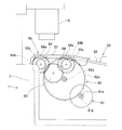
- the drive device 60 of the feeder 50 includes a motor 61, a reduction gear 62, an intermediate gear 63, and a pair of sprockets 64 as shown in FIG.
- the motor 61 is a stepping motor that is driven in synchronization with the pulse power supplied from the feeder controller 70.
- the motor 61 rotates the rotating shaft 61a according to the pulse power.
- a drive gear 61 b is provided on the rotation shaft 61 a of the motor 61.
- the reduction gear 62 and the intermediate gear 63 are rotatably supported by the case 51, respectively.
- the reduction gear 62 has a large-diameter gear 62a that meshes with the drive gear 61b of the motor 61, and a small-diameter gear 62b that has a smaller number of teeth than the large-diameter gear 62a.
- the intermediate gear 63 meshes with the small diameter gear 62 b of the reduction gear 62.
- the pair of sprockets 64 are respectively supported by the case 51 so as to be rotatable. On the outer peripheral surface of the pair of sprockets 64, an engaging protrusion 64a that can be engaged with a feed hole of the component tape is formed. A part of the engaging protrusion 64 a protrudes from the window 52 a formed on the rail 52 to the upper surface of the rail 52.
- Each of the pair of sprockets 64 has a driven gear 64b that meshes with the intermediate gear 63 at different phases. The pair of sprockets 64 are rotated by an angle corresponding to the above-described pulse power by receiving the reduced driving force.
- the feeder control unit 70 controls various operations in the feeder 50.
- the memory of the feeder control unit 70 stores setting values such as firmware executed in electronic component supply control and the correction amount.
- the feeder control unit 70 controls the transfer operation of the driving device 60 according to a command value input from the outside in a state where the feeder control unit 70 is communicably held in the slot of the component supply device or the feeder holding unit 3 of the measuring device 1. That is, the feeder control unit 70 functions as a driver that supplies pulse power to the motor 61.
- the feeder 50 is configured to be able to move the component tape in the specified transfer direction.
- the transfer direction is a direction along the rail 52 from the tape insertion portion Ni to the component extraction portion Nt.
- the transfer operation in which the feeder 50 moves the component tape includes continuous feed for continuously feeding the component tape and pitch feed for intermittently feeding at intervals of electronic components to be accommodated, for example.
- the feeder controller 70 controls the driving device 60 having the stepping motor (motor 61) by open loop control. That is, the feeder control unit 70 determines the frequency and number of pulses of pulse power based on the input command value, and supplies the pulse power to the motor 61.
- the feeder control unit 70 reflects the correction amount according to the state of the driving device 60 when determining the pulse power.
- the state of the drive device 60 includes, for example, the rotation angle of the reduction gear 62.
- the rotation angle of the reduction gear 62 is based on the state of the reduction gear 62 meshed with the drive gear 61b of the motor 61 with the motor 61 as a control origin angle, and the reduction gear 62 with the rotation of the motor 61 from this reference. Corresponds to the angle of rotation.
- the correction amount is set for each of the sections by dividing 360 degrees by the number of teeth of the large-diameter gear 62a of the reduction gear 62 according to the rotation angle of the reduction gear 62, for example.
- the correction amount for example, the number of pulses corresponding to the rotation angle based on the command value is set to increase or decrease at a constant rate.
- the reason why the correction amount is reflected when the feeder control unit 70 determines the pulse power is as follows.
- a reduction mechanism (a driving gear 61b, a reduction gear 62, an intermediate gear 63, and a driven gear 64b) that reduces the rotational speed of the driving force is interposed between the motor 61 and the pair of sprockets 64.
- This speed reduction mechanism has inherent non-uniformities such as uneven rotation caused by manufacturing errors, assembly errors of the feeder 50, and the like.
- the feeder control unit 70 is preset with a correction amount according to the state of the driving device 60, and determines the pulse power based on the input command value and the correction amount according to the current state. .
- the driving device 60 is supplied with the pulse power to the motor 61 and, as a result, transfers the component tape by the transfer amount corresponding to the command value.
- the measuring apparatus 1 includes a measuring jig used for measuring the operation accuracy of pitch feeding of the feeder 50.
- the measuring jig is a dedicated measuring tape 80 imitating a component tape as shown in FIG.
- the measuring tape 80 is formed of a material such as a metal that hardly deforms when transferred by the feeder 50.
- the measuring tape 80 has a tape body 81, a plurality of feed holes 82, and a plurality of measurement marks 83.
- the tape body 81 is set to a thickness corresponding to the component tape, and is formed by being stretched into a strip shape.
- the plurality of feed holes 82 are through holes arranged in the extending direction of the tape body 81 at the same interval as the feed holes of the component tape.
- the plurality of feed holes 82 are configured to be engageable with the engagement protrusions 64 a of the sprocket 64 of the feeder 50.
- the plurality of measurement marks 83 are arranged at a specified interval P (Wf> P) narrower than the width Wf in the transfer direction (vertical direction in FIG. 3) in the camera field of view 11 and along the transfer direction.
- the specified interval P is set so that a plurality of measurement marks 83 are included in the image data by one imaging by the measurement camera 10.
- the specified interval P is set to a value obtained by dividing the interval between electronic components accommodated in the component tape by an integer.
- the measurement mark 83 is a circular through hole formed by punching the tape body 81 in the present embodiment.
- the measuring tape 80 used as a measuring jig has a specified interval P in the transfer direction between adjacent measurement marks 83, the position of the measurement mark 83 in the tape width direction (transfer orthogonal direction), and the accuracy of the shape (in this embodiment).
- the accuracy of the circularity is guaranteed.
- the accuracy guaranteed by this corresponds to the accuracy required for measuring the operation accuracy in the measuring apparatus 1.
- the control device 20 of the measurement device 1 includes a movement control unit 21, an imaging control unit 22, an image processing unit 23, and an error measurement unit 24.
- the movement control unit 21 sends a command value to the driving device 60 via the feeder control unit 70 to position the measurement tape 80 at the command position in the transfer direction with respect to the measurement camera 10.
- the movement control unit 21 sends a command value to the feeder control unit 70 so as to transfer the measuring tape by a specified amount from the current state of the driving device 60, for example.
- the imaging control unit 22 captures the measured measurement tape 80 with the measurement camera 10 and acquires image data (corresponding to the camera field of view 11 in FIG. 3). Specifically, the imaging control unit 22 sends a control signal to the measurement camera 10 so that the measurement tape 80 partially stored in the camera field of view 11 of the measurement camera 10 is imaged. The imaging control unit 22 acquires image data obtained by imaging, and stores the image data in association with the command value sent by the movement control unit 21.
- the image processing unit 23 calculates the actual position of the measurement tape 80 based on a plurality of measurement marks 83 (see FIG. 3) included in the image data.
- the actual position of the measuring tape 80 is the actual position of the measuring tape 80 positioned on the rail 52 of the feeder 50.
- the image processing unit 23 employs a method using the reference mark 53 included in the same image data in the present embodiment.
- the image processing unit 23 calculates the relative position of the measurement mark 83 with respect to the position of the reference mark 53 included in the image data, and calculates the actual position of the measurement tape 80 based on the calculation result.
- the image processing unit 23 is configured to use a plurality of measurement marks 83 included in the image data for calculating the actual position of the measurement mark 83.
- the image processing unit 23 calculates the actual position of the measurement tape 80 averaged based on the positions of the plurality of measurement marks 83 and the specified interval P.
- the image processing unit 23 determines the validity of each measurement mark 83 based on the measurement mark information related to the plurality of measurement marks 83.
- the measurement mark information may include the positions of a plurality of measurement marks 83 in the image data (for example, plane coordinates with the reference mark 53 as the origin), the shape (the circularity of the measurement mark 83), and the like.
- the measurement mark information of the present embodiment includes the processing result of the position and shape recognition of the measurement mark 83.
- the position and shape of the measurement mark 83 recognized by the image processing may include an error depending on the imaging environment and the state of scratches on the surface of the measurement tape 80. Therefore, the image processing unit 23 is configured to calculate the actual position of the measurement tape 80 using the measurement mark 83 determined to be valid based on the measurement mark information among the plurality of measurement marks 83 included in the image data. . Details of the actual position by the image processing unit 23 will be described later.
- the error measuring unit 24 measures the positioning error in the transfer direction by the driving device 60 based on the command position corresponding to the command value sent to the feeder 50 and the actual position of the measuring tape 80. Specifically, the error measurement unit 24 calculates the difference between the actual distance in the transfer direction between the actual position of the measurement tape 80 calculated by the image processing unit 23 and the position of the reference mark 53 and the ideal distance based on the command position. Is acquired as a positioning error.
- a measurement process of the operation accuracy of the feeder 50 by the measurement apparatus 1 will be described.
- a mode in which the measuring apparatus 1 measures a positioning error in order to set an appropriate correction amount in the feeder 50 is illustrated.
- the feeder 50 loaded with the measuring tape 80 is set in the feeder holding unit 3 of the measuring apparatus 1.
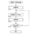
- the measuring apparatus 1 executes a preparation process for the feeder 50 held in the feeder holding unit 3 (step 11 (hereinafter, “step” is expressed as “S”)).
- step 11 (hereinafter, “step” is expressed as “S”)
- the control device 20 of the measuring apparatus 1 acquires an identification code for identifying the feeder 50 and a currently set correction amount by communicating with the feeder control unit 70 of the feeder 50.
- the control device 20 sends a command value to the feeder control unit 70 so as to return the motor 61 of the drive device 60 to the origin angle.
- the motor 61 is rotated to the control origin angle, and the drive gear 61b is brought into mesh with the large-diameter gear 62a of the reduction gear 62 at a predetermined phase.
- the movement control unit 21 sends a command value to the feeder control unit 70 so as to move the measuring tape 80 by one pitch (S12).
- the one pitch is set as appropriate, for example, an interval between electronic components housed in a component tape.
- one pitch is set to the transfer amount of the measuring tape 80 when the large-diameter gear 62a of the reduction gear 62 is rotated by one tooth.
- the feeder control unit 70 aims to set an appropriate correction amount in the feeder 50 for measurement of operation accuracy, and therefore does not apply the correction amount in the transfer of the measuring tape 80. That is, the feeder control unit 70 supplies a constant pulse power corresponding to one pitch to the driving device 60 and positions the measuring tape 80 at the command position where the pitch is fed.
- the imaging control unit 22 captures the measured measurement tape 80 with the measurement camera 10 and acquires image data (S13).
- the acquired image data is stored in the control device 20 in association with the command value sent from the movement control unit 21, more specifically in association with the number of pitch feeds accumulated from the origin angle of the motor 61. .
- control device 20 has performed the imaging process (S13) for the state of the driving device 60 divided by one pitch (in this embodiment, the state in which the large-diameter gear 62a of the reduction gear 62 is rotated by one tooth). It is determined whether or not (S14). The control device 20 repeats until the transfer operation (S12) and the imaging process (S13) are performed for all sections.
- the control device 20 executes a positioning error calculation process as shown in FIG.
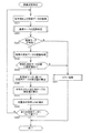
- the image processing unit 23 first acquires the command value sent by the movement control unit 21 and the image data associated with the command value (S21).
- the image processing unit 23 executes processing for recognizing the reference mark 53 included in the acquired image data (S22). Thereby, the reference mark information including the position and shape of the reference mark 53 in the image data is acquired.
- the image processing unit 23 determines whether or not the shape of the reference mark 53 in the reference mark information, specifically, the circularity is within an allowable range (S23). If the circularity of the reference mark 53 is not within the allowable range (S23: No), the error position (S31) is executed because the reference position in the image data cannot be obtained, and the operation accuracy measurement process of the feeder 50 is interrupted. To do.
- the image processing unit 23 executes a process of recognizing the plurality of measurement marks 83 (S24). Thereby, measurement mark information including the relative position and shape of each measurement mark 83 with the position of the reference mark 53 as the origin in the image data is acquired. Then, the image processing unit 23 determines whether the number of measurement marks 83 effective for measuring the operation accuracy is equal to or greater than the specified value Mn based on the measurement mark information (S25).
- the effectiveness of the measurement mark 83 is determined by the position and shape of the measurement mark 83.
- the image processing unit 23 first determines whether or not the circularity of the measurement mark 83 is within the allowable range, and excludes the measurement mark 83 that is not within the allowable range. Next, the image processing unit 23 acquires the separation distance in the tape width direction with respect to the reference mark 53 for the measurement mark 83 whose circularity is in an allowable range. Then, the image processing unit 23 excludes the measurement mark 83 whose acquired separation distance is not within the allowable range.
- the image processing unit 23 extracts the measurement mark 83 that is effective for the measurement process of the operation accuracy as described above. If the number of effective measurement marks 83 is less than the specified value Mn (S25: No), the actual position of the measurement tape 80 cannot be calculated based on the image data, and error processing (S31) is executed. Then, the measuring process of the operation accuracy of the feeder 50 is interrupted. On the other hand, when the number of effective measurement marks 83 is equal to or greater than the specified value Mn (S25: Yes), the image processing unit 23 calculates the actual position of the measurement tape 80 based on each measurement mark 83 (S26). ).
- the image processing unit 23 sets the measurement marks 83A to 83E.
- the actual distances Da to De in the transfer direction with respect to the reference mark 53 of 83E are calculated.
- the image processing unit 23 calculates the averaged actual position of the measurement tape 80 based on the actual distances Da to De of the effective measurement marks 83A to 83E and the specified interval P in the transfer direction (S27). .
- the error measuring unit 24 calculates a difference between the average actual distance Dv in the transport direction between the averaged actual position of the measuring tape 80 and the position of the reference mark 53 and the ideal distance Dm based on the command position as a positioning error ⁇ S. (S28).
- the control device 20 determines whether or not the calculation of the positioning error ⁇ S (S28) has been performed for all the image data (S29).
- the control device 20 repeats the above processing (S21 to S29) until the positioning error ⁇ S is calculated for all image data.
- the control device 20 calculates and stores a correction amount according to the state of the driving device 60 based on the positioning error ⁇ S calculated corresponding to each division by one pitch.
- the measuring device 1 supplies a constant pulse power to the driving device 60 and is actually measured by the theoretical transfer amount of the measuring tape 80 in each section and the plurality of measurement marks 83 included in the image data.
- An appropriate correction amount is calculated based on the transferred amount. This correction amount is transferred from the control device 20 to the feeder control unit 70 of the feeder 50 and used for controlling the transfer operation of the feeder 50.
- the measuring device 1 measures the operation accuracy of the driving device 60 with respect to a measured body (feeder 50) including the driving device 60 that moves the moving body (component tape) in a specified transfer direction.
- the measurement apparatus 1 includes a measurement camera 10 having a predetermined camera field of view 11 and a plurality of measurement marks 83 arranged along the transfer direction at a specified interval P narrower than the width Wf of the camera field of view 11 in the transfer direction.
- a tool (measuring tape 80), a movement control unit 21 for sending a command value to the driving device 60 and positioning the measuring jig (measuring tape 80) at a command position in the transfer direction, and a positioning measuring jig
- the imaging control unit 22 that captures (measurement tape 80) with the measurement camera 10 and obtains image data, and a plurality of measurement marks 83 included in the image data, the measurement jig (measurement tape 80) is actually implemented.
- the image processing unit 23 that calculates the position, and the error measurement unit 24 that measures the positioning error ⁇ S in the transfer direction by the driving device 60 based on the command position and the actual position.
- the measuring apparatus 1 calculates the actual position of the measuring tape 80 based on the plurality of measurement marks 83 (S26, S27).
- the plurality of measurement marks 83 indicate the actual positions of the measurement tape 80
- the measuring apparatus 1 can appropriately calculate the actual position of the measurement tape 80 by complementing the plurality of measurement marks 83 in the image data. Accordingly, it is possible to increase the number of times that the measuring tape 80 can be used and to extend the useful life.
- the image processing unit 23 acquires the positions of the plurality of measurement marks 83 in the image data, and averages the measurement jigs (measurement tape 80) based on the positions of the plurality of measurement marks 83 and the specified interval P. ) Is calculated. According to such a configuration, it is possible to reduce the influence on the image processing due to the posture of the measuring tape 80 and the change in the imaging environment. Thereby, since the actual position of the measuring tape 80 can be calculated more accurately, the measurement accuracy of the measuring apparatus 1 can be improved.
- the image processing unit 23 acquires measurement mark 83 information including the positions or shapes of the plurality of measurement marks 83 in the image data, and performs measurement using the measurement marks 83 determined to be valid based on the measurement mark 83 information.
- the actual position of the jig (measuring tape 80) is calculated.
- the measurement mark 83 unsuitable for image processing for calculating the actual position of the measurement tape 80 can be excluded, and the actual position of the measurement tape 80 can be calculated by complementing with the other measurement marks 83.
- a reference mark 53 is arranged on the measured object (feeder 50) at a position that fits in the camera visual field 11.
- the image processing unit 23 calculates the relative positions of the plurality of measurement marks 83 with respect to the reference mark 53 included in the image data, and calculates the actual position of the measurement jig (measurement tape 80) based on the calculation result. .
- the actual position of the measurement tape 80 is calculated using image data including the reference mark 53 and the plurality of measurement marks 83.
- the relative actual position of the measuring tape 80 with respect to the reference mark 53 can be calculated regardless of the position information (rotation angle, control position coordinates) of the driving device 60. Therefore, a sensor for detecting the position and angle of the driving device 60 is not required, and the operation accuracy of the driving device 60 can be measured.
- the measured object is a feeder 50 that supplies electronic components by pitching them in the transfer direction by the driving device 60 using a component tape containing electronic components as a moving body.
- the measuring jig is a measuring tape 80 formed so as to be pitch-feedable by the driving device 60 corresponding to the component tape.
- the measuring apparatus 1 measures the accuracy of the component tape transfer operation using the measuring tape 80 with the feeder 50 as a measurement target.
- the measuring tape 80 imitating a component tape is transferred through a tape conveyance path inside the feeder 50. Therefore, the surface of the measuring tape 80 may be scratched by sliding with a tape guide or the like. Such a scratch affects the recognition accuracy of the measurement mark 83 in image processing.
- the measuring apparatus 1 can appropriately calculate the actual position of the measuring jig (measuring tape 80) by appropriately complementing the plurality of measuring marks 83 in the image data. Therefore, it is particularly useful to apply the measuring apparatus 1 of the present invention to the measurement of the operation accuracy using the feeder 50 as the measurement object.
- the driving device 60 of the feeder 50 uses a stepping motor (motor 61).
- the control device of the feeder 50 performs open loop control of the stepping motor based on a command input from the outside, and pitches the component tape.
- the apparatus configuration can be simplified and the control load can be reduced as compared with feedback control, while the correction amount during operation directly affects the operation accuracy. Therefore, it is required to set a more appropriate correction amount corresponding to the drive device 60 that is controlled by the open loop.
- the measurement apparatus 1 can improve the measurement accuracy of the measurement apparatus 1 because the positional relationship between the plurality of measurement marks 83 is reflected in the measurement accuracy of the measurement apparatus 1. Therefore, the correction amount used for the open loop control can be set more appropriately. Therefore, it is particularly useful to apply the measuring device 1 of the present invention to the measurement of the operation accuracy of the feeder 50 including the driving device 60 driven by open loop control.
- the measuring apparatus 1 uses the at least one effective measurement mark 83 for measurement when the purpose is to increase the number of times of use of the measuring tape 80 as a measuring jig or to extend the useful life.
- the actual position of the tape 80 may be calculated.
- the measuring apparatus 1 sets the specified value Mn to 1. According to such a configuration, the measurement apparatus 1 performs image processing on a plurality of measurement marks 83 included in the image data, and uses the measurement tape 80 except when all the measurement marks 83 are not valid. Operation accuracy can be measured.
- the measurement mark 83 is used for measurement due to the influence of dirt and scratches on the periphery. If it is determined that it is not valid, the operation accuracy measurement process is interrupted.
- image processing is performed on a plurality of measurement marks 83 that can be accommodated in the camera field of view 11, and the measurement processing of operation accuracy is continued due to the remaining of at least one effective measurement mark 83. it can.
- the measuring apparatus 1 since at least one of the plurality of measurement marks 83 indicates the actual position of the measurement tape 80, the measuring apparatus 1 appropriately complements the plurality of measurement marks 83 in the image data to determine the actual position of the measurement tape 80. It can be calculated. Accordingly, it is possible to increase the number of times that the measuring tape 80 can be used and to extend the useful life.
- the mode exemplified in the embodiment (the mode in which the specified value Mn is set to 2 or more) is preferable.
- the image processing unit 23 calculates the actual position of the averaged measurement tape 80 based on the plurality of effective measurement marks 83 and the specified interval P in the transfer direction (S27). On the other hand, the image processing unit 23 may adopt various modes as long as the actual position of the measurement tape 80 is calculated based on the plurality of measurement marks 83 included in the image data.
- a configuration is assumed in which the actual position of the measurement tape 80 is calculated by extracting a predetermined number of measurement marks 83 in order from the highest circularity among the plurality of recognized measurement marks 83.
- the This is a configuration using the fact that the higher the circularity of the measurement marks 83, the more accurate the actual position can be considered.
- the control device 20 may present the result of the image processing together.
- the reliability of the measurement results and the replacement time of the measuring tape 80 can be determined by presenting the ratio of the effective measurement marks 83 among the plurality of measurement marks 83 included in the image data and the circularity of each. It is possible to guide.
- the reference mark 53 provided on the feeder 50 and the measurement mark 83 arranged on the measurement tape 80 are formed in a circular shape.
- various shapes can be adopted.
- the measurement mark 83 may be formed on the surface of the tape body 81 by processing such as laser marking instead of the through hole.
- the feeder 50 is provided with one reference mark 53.
- the feeder 50 is provided with a plurality of reference marks 53, and the measuring apparatus 1 performs image processing on the plurality of reference marks 53 included in the image data to calculate the actual position of the measuring tape 80. It is good also as composition to do.
- the fiducial marks 53 are respectively arranged at a plurality of different positions that can be accommodated in the camera visual field 11 in the feeder 50 that is a measurement object.
- the image processing unit 23 calculates the relative positions of the plurality of measurement marks 83 with respect to the plurality of reference marks 53 included in the image data, and calculates the actual position of the measurement tape 80 based on the calculation result.
- the relative positions of the plurality of reference marks 53 and the plurality of measurement marks 83 are reflected in the measurement accuracy of the measurement apparatus 1. Therefore, the measurement accuracy of the measuring device 1 can be further improved. Further, the measuring apparatus 1 can calculate the actual position of the measuring tape 80 by appropriately complementing the plurality of reference marks 53 in the image data. As a result, the service life of the reference mark 53 can be extended.
- the image processing unit 23 performs the plurality of reference marks 53 similarly to the determination of the effectiveness of the measurement mark 83 in the embodiment (S25). It is good also as a structure which determines the effectiveness with respect to. Specifically, the image processing unit 23 acquires reference mark information including the positions or shapes of the plurality of reference marks 53 in the image data, and uses the reference marks 53 determined to be valid based on the reference mark information. The actual position of the measuring tape 80 is calculated.
- the reference mark 53 that is not effective for image processing for calculating the actual position of the measurement tape 80 can be excluded.
- the actual position of the measuring tape 80 can be calculated by complementing each other. Accordingly, it is possible to extend the useful life of the reference mark 53 of the feeder 50 as compared with a configuration in which error processing is performed when the only reference mark 53 is not effective for image processing.
- the measuring device 1 measures the operation accuracy of the driving device 60 in the feeder 50 for the purpose of setting an appropriate correction amount in the feeder 50.
- the measuring device 1 is used for measuring the operation accuracy of the driving device 60 in the feeder 50 for the purpose of inspecting whether the set correction amount is appropriate, for example.
- the control device 20 of the measurement device 1 applies a correction amount set in advance to the operation control of the drive device 60 to the feeder control unit 70 of the feeder 50.
- the pulse power corresponding to one pitch in the transfer operation (corresponding to S12 in the embodiment) is the number of pulses reflecting the correction amount according to the state of the driving device 60 (for example, the rotation angle of the reduction gear 62). It is determined.
- the measuring apparatus 1 calculates the actual position of the measuring tape 80 based on the image data as in the embodiment, thereby obtaining the difference between the corrected theoretical transport amount and the actually measured transport amount. .
- the measuring apparatus 1 can inspect whether the correction amount is appropriate depending on whether or not the difference between the acquired transfer amounts is within an allowable range.
- the measuring apparatus 1 uses the feeder 50 as an object to be measured, and is used for measuring the operation accuracy of the driving device 60 of the feeder 50.
- the measuring device can be applied to the measurement of the operation accuracy of the driving device as long as the measuring device includes a driving device that moves the moving body in a specified transfer direction. It is.
- the measuring apparatus can be applied as an apparatus for inspecting the accuracy of the electronic component transfer operation in the component mounter (see Patent Document 2: Japanese Patent Laid-Open No. 2005-216974).
- the moving body is a mounting head that holds an electronic component.
- the drive device is a drive device (XY robot) that moves the mounting head in the XY directions.
- the measurement camera which comprises a measuring apparatus is provided in a drive device with a mounting head.
- the measuring device measures the operational accuracy using the matrix substrate arranged in the movable range of the driving device in the component mounter as a measuring jig. That is, the measurement apparatus repeats a transfer operation in a specified transfer direction (for example, the X direction) by the driving device and an operation of imaging an index mark (corresponding to the “measurement mark” of the present invention) provided on the matrix substrate. .
- a plurality of index marks arranged in a prescribed transfer direction are set at a prescribed interval and are arranged so as to fit in the camera field of view of the measurement camera.
- the measurement apparatus acquires image data by imaging, and performs image processing as in the embodiment for a plurality of index marks included in the image data. Then, the measuring device measures the operation accuracy of the driving device based on the control position of the mounting head when imaged and the actual position of the mounting head calculated as a relative position with respect to the matrix substrate by image processing. According to such a configuration, the same effects as in the embodiment can be obtained.
- the measurement accuracy of the measurement device can be improved.
- a plurality of index marks indicate the actual position of the mounting head with respect to the matrix substrate.
- the measuring apparatus can appropriately complement the plurality of index marks in the image data and calculate the actual position of the mounting head. Therefore, it is possible to extend the useful life of the matrix substrate that is a measurement jig.
- the measuring apparatus does not necessarily require the reference mark 53 that can be accommodated in the camera field of view 11 in a configuration that can recognize the coordinate position on the control of the moving body (mounting head). That is, in the aspect illustrated in the embodiment, if the accuracy of the positional relationship between the feeder 50 held by the feeder holding unit 3 and the measurement camera 10 is assured, for example, the center of the image data is used as a reference.
- the mark 53 can be omitted.
- the actual position of the measurement tape 80 be calculated based on one image data regardless of the installation accuracy of the measurement camera 10. That is, as illustrated in the embodiment, the reference mark 53 is provided at a position that fits in the camera visual field 11, and the measurement jig (measuring tape 80) is actually measured based on the relative positions of the plurality of measurement marks 83 with respect to the reference mark 53. A configuration for calculating the position is preferable.
Landscapes
- Engineering & Computer Science (AREA)
- Microelectronics & Electronic Packaging (AREA)
- Manufacturing & Machinery (AREA)
- Physics & Mathematics (AREA)
- General Physics & Mathematics (AREA)
- Operations Research (AREA)
- Computer Vision & Pattern Recognition (AREA)
- Theoretical Computer Science (AREA)
- Supply And Installment Of Electrical Components (AREA)
- Length Measuring Devices By Optical Means (AREA)
Abstract
Description
(測定装置1の構成)
測定装置1は、例えばフィーダ保守装置に組み込まれ、フィーダ50の移送動作の精度を測定する。本実施形態において、フィーダ50の測定装置1は、図1に示すように、基台2に設けられたフィーダ保持部3により被測定体であるフィーダ50を保持する。測定装置1に保持されたフィーダ50は、電力を供給されるとともに、後述する制御装置20と通信可能な状態となる。
フィーダ50は、図示しない部品実装機における部品供給装置のスロットにセットされる。フィーダ50は、リールに巻回された部品テープ(本発明の「移動体」に相当する)をピッチ送りして、取出し部Ntにおいて電子部品を取り出し可能に供給する。
測定装置1は、フィーダ50のピッチ送りの動作精度の測定に用いられる測定治具を備える。本実施形態において、測定治具は、図3に示すように、部品テープを模した専用の測定用テープ80である。測定用テープ80は、フィーダ50により移送された場合に変形が生じにくい金属などの材料により形成される。測定用テープ80は、テープ本体81と、複数の送り穴82と、複数の測定マーク83とを有する。
測定装置1の制御装置20は、図1に示すように、移動制御部21と、撮像制御部22と、画像処理部23と、誤差測定部24とを備える。移動制御部21は、フィーダ制御部70を介して駆動装置60に指令値を送出して、測定カメラ10に対して測定用テープ80を移送方向の指令位置に位置決めする。移動制御部21は、フィーダ制御部70に対して、例えば現在の駆動装置60の状態から規定量だけ測定用テープを移送するように指令値を送出する。
上記の測定装置1によるフィーダ50の動作精度の測定処理について説明する。なお、ここでは、フィーダ50に適正な補正量を設定するために、測定装置1が位置決め誤差を測定する態様を例示する。また、測定処理に際して、測定用テープ80が装填されたフィーダ50が測定装置1のフィーダ保持部3にセットされる。
測定装置1は、移動体(部品テープ)を規定の移送方向に移動させる駆動装置60を備える被測定体(フィーダ50)を対象として、駆動装置60の動作精度を測定する。測定装置1は、所定のカメラ視野11を有する測定カメラ10と、カメラ視野11における移送方向の幅Wfより狭い規定間隔Pで且つ移送方向に沿って配列された複数の測定マーク83を有する測定治具(測定用テープ80)と、駆動装置60に指令値を送出して、測定治具(測定用テープ80)を移送方向の指令位置に位置決めする移動制御部21と、位置決めされた測定治具(測定用テープ80)を測定カメラ10により撮像して画像データを取得する撮像制御部22と、画像データに含まれる複数の測定マーク83に基づいて、測定治具(測定用テープ80)の実位置を算出する画像処理部23と、指令位置および実位置に基づいて、駆動装置60による移送方向の位置決め誤差ΔSを測定する誤差測定部24と、を備える。
このような構成によると、測定用テープ80の姿勢や、撮像環境の変動などによる画像処理への影響を低減できる。これにより、測定用テープ80の実位置をより正確に算出できるので、測定装置1の測定精度を向上できる。
このような構成によると、測定用テープ80の実位置を算出する画像処理に不適な測定マーク83を除外するとともに、他の測定マーク83により補完して測定用テープ80の実位置を算出できる。これにより、一の測定マーク83が画像処理に不適の場合にエラー処理を行う構成と比較して、測定用テープ80の耐用回数の増加や耐用期間の延長を図ることができる。
このような構成によると、基準マーク53および複数の測定マーク83が含まれる画像データを用いて、測定用テープ80の実位置が算出される。これにより、駆動装置60の位置情報(回転角度、制御上の位置座標)によらず、基準マーク53に対する測定用テープ80の相対的な実位置を算出できる。よって、駆動装置60の位置や角度を検出するセンサを要さず、駆動装置60の動作精度を測定できる。
このような構成によると、測定装置1は、フィーダ50を被測定体として、測定用テープ80を用いて部品テープの移送動作の精度を測定する。動作精度の測定において、部品テープを模した測定用テープ80は、フィーダ50内部におけるテープ搬送路を移送される。そのため、測定用テープ80の表面には、テープガイドなどとの摺動により擦り傷などが生じることがある。
このような擦り傷は、画像処理における測定マーク83の認識精度に影響する。これに対して、上記のような構成により、測定装置1は、画像データにおける複数の測定マーク83を適宜補完して測定治具(測定用テープ80)の実位置を算出できる。よって、フィーダ50を被測定体とする動作精度の測定に本発明の測定装置1を適用することは特に有用である。
そのため、オープンループ制御される駆動装置60に対応して、より適正な補正量の設定が要求される。これに対して、上記のような構成により、測定装置1は、複数の測定マーク83同士の位置関係が測定装置1の測定精度に反映されるので、測定装置1の測定精度を向上できる。よって、オープンループ制御に用いられる補正量をより適正に設定することができる。従って、オープンループ制御により駆動する駆動装置60を備えるフィーダ50の動作精度の測定に本発明の測定装置1を適用することは特に有用である。
(測定装置1の適用について)
実施形態において、測定装置1は、フィーダ50の動作精度の測定の精度向上を目的として、複数の測定マーク83を用いて測定用テープ80の実位置を算出する構成とした。具体的には、測定装置1は、動作精度の測定に有効な測定マーク83の数が規定値Mn(=2)以上である場合に(S25:Yes)、位置決め誤差の測定を行う(S26~S28)。
実施形態において、画像処理部23は、複数の有効な測定マーク83および移送方向の規定間隔Pに基づいて、平均化された測定用テープ80の実位置を算出する(S27)。これに対して、画像処理部23は、画像データに含まれる複数の測定マーク83に基づいて、測定用テープ80の実位置を算出するのであれば種々の態様を採用し得る。
実施形態において、フィーダ50に設けられる基準マーク53、および測定用テープ80に配列される測定マーク83は、円形に形成される。これに対して、基準マーク53および測定マーク83は、規定の形状をなしていれば、種々の形状を採用し得る。また、測定マーク83は、貫通孔に換えて、例えばテープ本体81の表面にレーザーマーキングなどの加工により形成される構成としてもよい。
実施形態において、測定装置1は、フィーダ50に適正な補正量を設定することを目的として、フィーダ50における駆動装置60の動作精度の測定を行う。これに対して、測定装置1は、例えば、設定された補正量が適正であるかを検査することを目的として、フィーダ50における駆動装置60の動作精度の測定に用いられる。
10:測定カメラ
20:制御装置
21:移動制御部、 22:撮像制御部、 23:画像処理部
24:誤差測定部
50:フィーダ(被測定体)
51:ケース、 52:レール、 52a:窓部
53:基準マーク
60:駆動装置
61:モータ、 61a:回転軸、 61b:駆動ギヤ
62:減速ギヤ、 62a:大径ギヤ、 62b:小径ギヤ
63:中間ギヤ
64:スプロケット、 64a:係合突起、 64b:被駆動ギヤ
70:フィーダ制御部
80:測定用テープ(測定治具)
81:テープ本体、 82:送り孔
83,83A~83E:測定マーク
Fc:カメラ視野、 Wf:(カメラ視野の移送方向の)幅
P:(測定マークの)規定間隔
Da~De:実距離、 Dm:理想距離
Mn:規定値、 ΔS:位置決め誤差
Ni:テープ挿入部、 Nt:部品取出し部
Claims (7)
- 移動体を規定の移送方向に移動させる駆動装置を備える被測定体を対象として、前記駆動装置の動作精度を測定する測定装置であって、
所定のカメラ視野を有する測定カメラと、
前記カメラ視野における前記移送方向の幅より狭い規定間隔で且つ前記移送方向に沿って配列された複数の測定マークを有する測定治具と、
前記駆動装置に指令値を送出して、前記測定治具を前記移送方向の指令位置に位置決めする移動制御部と、
位置決めされた前記測定治具を前記測定カメラにより撮像して画像データを取得する撮像制御部と、
前記画像データに含まれる複数の前記測定マークに基づいて、前記測定治具の実位置を算出する画像処理部と、
前記指令位置および前記実位置に基づいて、前記駆動装置による前記移送方向の位置決め誤差を測定する誤差測定部と、
を備える測定装置。 - 前記画像処理部は、前記画像データにおける複数の前記測定マークの位置をそれぞれ取得して、複数の前記測定マークの位置および前記規定間隔に基づいて平均化された前記測定治具の前記実位置を算出する、請求項1に記載の測定装置。
- 前記画像処理部は、前記画像データにおける複数の前記測定マークの位置または形状を含む測定マーク情報を取得して、前記測定マーク情報に基づいて有効と判定された前記測定マークを用いて前記測定治具の前記実位置を算出する、請求項1または2に記載の測定装置。
- 前記被測定体には、前記カメラ視野に収まる位置に基準マークが配置され、
前記画像処理部は、前記画像データに含まれる前記基準マークに対する複数の前記測定マークの相対位置を算出して、当該算出の結果に基づいて前記測定治具の前記実位置を算出する、請求項1~3の何れか一項に記載の測定装置。 - 前記被測定体には、前記カメラ視野に収まる異なる複数の位置に前記基準マークがそれぞれ配置され、
前記画像処理部は、前記画像データに含まれる複数の前記基準マークに対する複数の前記測定マークの相対位置をそれぞれ算出して、当該算出の結果に基づいて前記測定治具の前記実位置を算出する、請求項4に記載の測定装置。 - 前記画像処理部は、前記画像データにおける複数の前記基準マークの位置または形状を含む基準マーク情報を取得して、前記基準マーク情報に基づいて有効と判定された前記基準マークを用いて前記測定治具の前記実位置を算出する、請求項5に記載の測定装置。
- 前記被測定体は、電子部品を収容する部品テープを前記移動体として、前記駆動装置により前記移送方向にピッチ送りして前記電子部品を供給するフィーダであり、
前記測定治具は、前記部品テープに対応して前記駆動装置によりピッチ送り可能に形成された測定用テープである、請求項1~6の何れか一項に記載の測定装置。
Priority Applications (5)
| Application Number | Priority Date | Filing Date | Title |
|---|---|---|---|
| US15/749,676 US10765049B2 (en) | 2015-08-19 | 2015-08-19 | Measurement device |
| PCT/JP2015/073253 WO2017029730A1 (ja) | 2015-08-19 | 2015-08-19 | 測定装置 |
| EP15901712.8A EP3340759B1 (en) | 2015-08-19 | 2015-08-19 | Measurement device |
| CN201580082344.4A CN107926142B (zh) | 2015-08-19 | 2015-08-19 | 测定装置 |
| JP2017535193A JP6615206B2 (ja) | 2015-08-19 | 2015-08-19 | 測定装置 |
Applications Claiming Priority (1)
| Application Number | Priority Date | Filing Date | Title |
|---|---|---|---|
| PCT/JP2015/073253 WO2017029730A1 (ja) | 2015-08-19 | 2015-08-19 | 測定装置 |
Publications (1)
| Publication Number | Publication Date |
|---|---|
| WO2017029730A1 true WO2017029730A1 (ja) | 2017-02-23 |
Family
ID=58051300
Family Applications (1)
| Application Number | Title | Priority Date | Filing Date |
|---|---|---|---|
| PCT/JP2015/073253 Ceased WO2017029730A1 (ja) | 2015-08-19 | 2015-08-19 | 測定装置 |
Country Status (5)
| Country | Link |
|---|---|
| US (1) | US10765049B2 (ja) |
| EP (1) | EP3340759B1 (ja) |
| JP (1) | JP6615206B2 (ja) |
| CN (1) | CN107926142B (ja) |
| WO (1) | WO2017029730A1 (ja) |
Cited By (2)
| Publication number | Priority date | Publication date | Assignee | Title |
|---|---|---|---|---|
| JP2022053723A (ja) * | 2020-09-25 | 2022-04-06 | パナソニックIpマネジメント株式会社 | 検査用治具およびテープフィーダの検査方法 |
| WO2025009064A1 (ja) * | 2023-07-04 | 2025-01-09 | 株式会社Fuji | フィーダ検査装置およびフィーダセットアップ装置 |
Families Citing this family (2)
| Publication number | Priority date | Publication date | Assignee | Title |
|---|---|---|---|---|
| CN110068571B (zh) * | 2019-03-14 | 2021-05-04 | 天津大学 | 一种织物尺寸变化率自动测量方法 |
| TWI701451B (zh) * | 2019-08-21 | 2020-08-11 | 頎邦科技股份有限公司 | 軟性電路板之輔助量測線路 |
Citations (2)
| Publication number | Priority date | Publication date | Assignee | Title |
|---|---|---|---|---|
| JP2009130092A (ja) * | 2007-11-22 | 2009-06-11 | Juki Corp | 部品供給装置のテープフィーダ |
| JP2011011748A (ja) * | 2009-06-30 | 2011-01-20 | Tesetsuku:Kk | テーピング装置 |
Family Cites Families (11)
| Publication number | Priority date | Publication date | Assignee | Title |
|---|---|---|---|---|
| JP2934546B2 (ja) * | 1991-12-11 | 1999-08-16 | 啓装工業株式会社 | チップ実装装置用カセットの検査方法及びその検査装置 |
| US5754677A (en) * | 1994-10-25 | 1998-05-19 | Fuji Machine Mfg. Co., Ltd. | Image processing apparatus |
| DE19922363A1 (de) * | 1999-05-14 | 2000-11-23 | Rexroth Star Gmbh | Einrichtung zur Ermittlung der Relativposition zweier relativ zueinander beweglicher Körper und Verfahren zur Herstellung einer solchen Einrichtung |
| JP4326641B2 (ja) * | 1999-11-05 | 2009-09-09 | 富士機械製造株式会社 | 装着装置,装着精度検出治具セットおよび装着精度検出方法 |
| JP3566166B2 (ja) * | 2000-02-10 | 2004-09-15 | 株式会社新川 | ツール位置測定方法、オフセット測定方法、基準部材およびボンディング装置 |
| JP4516220B2 (ja) * | 2001-01-15 | 2010-08-04 | 富士機械製造株式会社 | 部品装着精度関連部分の相対位置関係取得方法および電気部品装着システム |
| JP2003101294A (ja) | 2001-09-20 | 2003-04-04 | Fuji Mach Mfg Co Ltd | 電気部品供給方法および電気部品装着システム |
| JP3992486B2 (ja) * | 2001-12-07 | 2007-10-17 | 富士機械製造株式会社 | 電気部品装着システム |
| EP1343363A1 (en) * | 2002-03-08 | 2003-09-10 | TraceXpert A/S | Feeder verification with a camera |
| JP4371832B2 (ja) | 2004-01-27 | 2009-11-25 | 富士機械製造株式会社 | 電子部品実装装置における移動台の移動制御方法およびその方法に用いられるマトリックス基板 |
| JP5524495B2 (ja) * | 2009-03-10 | 2014-06-18 | 富士機械製造株式会社 | 撮像システムおよび電子回路部品装着機 |
-
2015
- 2015-08-19 WO PCT/JP2015/073253 patent/WO2017029730A1/ja not_active Ceased
- 2015-08-19 US US15/749,676 patent/US10765049B2/en active Active
- 2015-08-19 EP EP15901712.8A patent/EP3340759B1/en active Active
- 2015-08-19 CN CN201580082344.4A patent/CN107926142B/zh active Active
- 2015-08-19 JP JP2017535193A patent/JP6615206B2/ja active Active
Patent Citations (2)
| Publication number | Priority date | Publication date | Assignee | Title |
|---|---|---|---|---|
| JP2009130092A (ja) * | 2007-11-22 | 2009-06-11 | Juki Corp | 部品供給装置のテープフィーダ |
| JP2011011748A (ja) * | 2009-06-30 | 2011-01-20 | Tesetsuku:Kk | テーピング装置 |
Non-Patent Citations (1)
| Title |
|---|
| See also references of EP3340759A4 * |
Cited By (3)
| Publication number | Priority date | Publication date | Assignee | Title |
|---|---|---|---|---|
| JP2022053723A (ja) * | 2020-09-25 | 2022-04-06 | パナソニックIpマネジメント株式会社 | 検査用治具およびテープフィーダの検査方法 |
| JP7445835B2 (ja) | 2020-09-25 | 2024-03-08 | パナソニックIpマネジメント株式会社 | 検査用治具およびテープフィーダの検査方法 |
| WO2025009064A1 (ja) * | 2023-07-04 | 2025-01-09 | 株式会社Fuji | フィーダ検査装置およびフィーダセットアップ装置 |
Also Published As
| Publication number | Publication date |
|---|---|
| CN107926142A (zh) | 2018-04-17 |
| JP6615206B2 (ja) | 2019-12-04 |
| CN107926142B (zh) | 2021-05-11 |
| EP3340759A4 (en) | 2018-10-10 |
| EP3340759A1 (en) | 2018-06-27 |
| EP3340759B1 (en) | 2021-12-29 |
| US10765049B2 (en) | 2020-09-01 |
| US20180235119A1 (en) | 2018-08-16 |
| JPWO2017029730A1 (ja) | 2018-05-31 |
Similar Documents
| Publication | Publication Date | Title |
|---|---|---|
| US9054145B2 (en) | Substrate transfer apparatus | |
| CN103609209B (zh) | 元件安装机 | |
| JP6286726B2 (ja) | ボンディング装置およびボンディング方法 | |
| US10334770B2 (en) | Component holding state detection method and component mounting machine | |
| EP3232756B1 (en) | Component-mounting device | |
| EP2978296A1 (en) | Component mounting device and method of calibration in component mounting device | |
| JP6615206B2 (ja) | 測定装置 | |
| JP6298064B2 (ja) | 部品実装機 | |
| JP2009027015A (ja) | 電子部品装着方法及び電子部品装着装置 | |
| WO2012144282A1 (ja) | 電気部品装着機および電気回路製造方法 | |
| WO2019043892A1 (ja) | 部品装着機及び部品装着方法 | |
| EP1494522B1 (en) | Electronic component feeding device and electronic component mounting apparatus having the same | |
| EP2981162B1 (en) | Manufacturing equipment | |
| JP2009212251A (ja) | 部品移載装置 | |
| US9457977B2 (en) | Tape feeder and tape feeder cabinet | |
| EP3691432B1 (en) | Component mounting machine | |
| JP2006210705A (ja) | 電子部品実装装置 | |
| JP2002118396A (ja) | 電子部品実装装置および電子部品実装方法 | |
| JP4931772B2 (ja) | 電子部品実装装置 | |
| JP2012049451A (ja) | 部品実装装置及び部品実装方法 | |
| JP3946021B2 (ja) | 部品実装方法および部品実装機 | |
| JP6620057B2 (ja) | 部品実装装置および部品実装装置の被計測物の高さ取得方法 | |
| KR100702952B1 (ko) | 테이프 피이더 및 이를 구비한 전자부품 실장장치 | |
| JP2020136620A (ja) | 部品供給装置および部品供給装置の制御方法 | |
| JP2010120123A (ja) | 直交ロボット、該直交ロボットを備えた部品実装装置および前記直交ロボットの制御方法 |
Legal Events
| Date | Code | Title | Description |
|---|---|---|---|
| 121 | Ep: the epo has been informed by wipo that ep was designated in this application |
Ref document number: 15901712 Country of ref document: EP Kind code of ref document: A1 |
|
| ENP | Entry into the national phase |
Ref document number: 2017535193 Country of ref document: JP Kind code of ref document: A |
|
| WWE | Wipo information: entry into national phase |
Ref document number: 15749676 Country of ref document: US |
|
| NENP | Non-entry into the national phase |
Ref country code: DE |
|
| WWE | Wipo information: entry into national phase |
Ref document number: 2015901712 Country of ref document: EP |