WO2017029885A1 - 画像生成装置、及び画像表示制御装置 - Google Patents
画像生成装置、及び画像表示制御装置 Download PDFInfo
- Publication number
- WO2017029885A1 WO2017029885A1 PCT/JP2016/068873 JP2016068873W WO2017029885A1 WO 2017029885 A1 WO2017029885 A1 WO 2017029885A1 JP 2016068873 W JP2016068873 W JP 2016068873W WO 2017029885 A1 WO2017029885 A1 WO 2017029885A1
- Authority
- WO
- WIPO (PCT)
- Prior art keywords
- panoramic image
- image
- sphere
- point
- image generation
- Prior art date
- Legal status (The legal status is an assumption and is not a legal conclusion. Google has not performed a legal analysis and makes no representation as to the accuracy of the status listed.)
- Ceased
Links
Images







Classifications
-
- G—PHYSICS
- G06—COMPUTING OR CALCULATING; COUNTING
- G06T—IMAGE DATA PROCESSING OR GENERATION, IN GENERAL
- G06T3/00—Geometric image transformations in the plane of the image
- G06T3/10—Selection of transformation methods according to the characteristics of the input images
-
- G—PHYSICS
- G06—COMPUTING OR CALCULATING; COUNTING
- G06T—IMAGE DATA PROCESSING OR GENERATION, IN GENERAL
- G06T3/00—Geometric image transformations in the plane of the image
- G06T3/08—Projecting images onto non-planar surfaces, e.g. geodetic screens
-
- G—PHYSICS
- G06—COMPUTING OR CALCULATING; COUNTING
- G06T—IMAGE DATA PROCESSING OR GENERATION, IN GENERAL
- G06T3/00—Geometric image transformations in the plane of the image
- G06T3/06—Topological mapping of higher dimensional structures onto lower dimensional surfaces
- G06T3/073—Transforming surfaces of revolution to planar images, e.g. cylindrical surfaces to planar images
-
- H—ELECTRICITY
- H04—ELECTRIC COMMUNICATION TECHNIQUE
- H04N—PICTORIAL COMMUNICATION, e.g. TELEVISION
- H04N9/00—Details of colour television systems
- H04N9/12—Picture reproducers
- H04N9/31—Projection devices for colour picture display, e.g. using electronic spatial light modulators [ESLM]
- H04N9/3179—Video signal processing therefor
- H04N9/3185—Geometric adjustment, e.g. keystone or convergence
-
- G—PHYSICS
- G06—COMPUTING OR CALCULATING; COUNTING
- G06T—IMAGE DATA PROCESSING OR GENERATION, IN GENERAL
- G06T3/00—Geometric image transformations in the plane of the image
-
- G—PHYSICS
- G06—COMPUTING OR CALCULATING; COUNTING
- G06T—IMAGE DATA PROCESSING OR GENERATION, IN GENERAL
- G06T3/00—Geometric image transformations in the plane of the image
- G06T3/40—Scaling of whole images or parts thereof, e.g. expanding or contracting
- G06T3/4007—Scaling of whole images or parts thereof, e.g. expanding or contracting based on interpolation, e.g. bilinear interpolation
-
- G—PHYSICS
- G06—COMPUTING OR CALCULATING; COUNTING
- G06T—IMAGE DATA PROCESSING OR GENERATION, IN GENERAL
- G06T7/00—Image analysis
- G06T7/10—Segmentation; Edge detection
-
- H—ELECTRICITY
- H04—ELECTRIC COMMUNICATION TECHNIQUE
- H04N—PICTORIAL COMMUNICATION, e.g. TELEVISION
- H04N1/00—Scanning, transmission or reproduction of documents or the like, e.g. facsimile transmission; Details thereof
- H04N1/387—Composing, repositioning or otherwise geometrically modifying originals
-
- H—ELECTRICITY
- H04—ELECTRIC COMMUNICATION TECHNIQUE
- H04N—PICTORIAL COMMUNICATION, e.g. TELEVISION
- H04N23/00—Cameras or camera modules comprising electronic image sensors; Control thereof
- H04N23/60—Control of cameras or camera modules
- H04N23/698—Control of cameras or camera modules for achieving an enlarged field of view, e.g. panoramic image capture
-
- H—ELECTRICITY
- H04—ELECTRIC COMMUNICATION TECHNIQUE
- H04N—PICTORIAL COMMUNICATION, e.g. TELEVISION
- H04N5/00—Details of television systems
- H04N5/222—Studio circuitry; Studio devices; Studio equipment
- H04N5/262—Studio circuits, e.g. for mixing, switching-over, change of character of image, other special effects ; Cameras specially adapted for the electronic generation of special effects
- H04N5/265—Mixing
Definitions
- the present invention relates to an image generation device that generates a panoramic image, an image display control device that displays a panoramic image, an image generation method, a program, and image data.
- the equidistant cylindrical projection is known as an image format of a panoramic image obtained by projecting the view of the whole sky from the observation point onto a two-dimensional plane.
- a rectangular image data having an aspect ratio of 1: 2 includes an omnidirectional landscape of 360 degrees horizontally and 180 degrees vertically.
- the entire upper side of the image corresponds to one point on the zenith (directly above), and the entire lower side corresponds to one point on the nadir (directly below). Therefore, in the area near the upper side or the lower side (an area including a view directed directly above or below the view as viewed from the observation point), the area in the middle of the image includes a view near the horizon. The amount of information per pixel becomes extremely small, and information waste is increased.
- the present invention has been made in consideration of the above situation, and one of the objects is an image generation apparatus, an image display control apparatus, and an image generation method capable of reducing waste of information contained in a panoramic image. Program and providing image data.
- the image generation apparatus is eight pieces obtained by dividing the surface of a sphere obtained by projecting the view seen from the observation point into at least a partial range by three planes orthogonal to each other through the center of the sphere.
- a panoramic image generation unit that generates an image, and an image output unit that outputs the generated panoramic image are characterized.
- the image display control device is obtained by dividing the surface of a sphere obtained by projecting the view seen from the observation point into at least a partial range by three planes orthogonal to each other through the center of the sphere. At least one of the eight divided areas, which includes the projected area of the scene, is converted so as to decrease as the number of pixels corresponding to equal latitudes becomes higher, and arranged on a plane. Including an acquisition unit for acquiring a panoramic image and a drawing unit for drawing a display image showing a view of a given view range based on the acquired panoramic image and displaying the display image on a screen of a display device. It features.
- the image generation method according to the present invention can be obtained by dividing the surface of a sphere obtained by projecting the view seen from the observation point into at least a partial range by three planes orthogonal to each other through the center of the sphere. Of the eight divided areas, at least one of the divided areas including the projected area of the scene is converted so as to decrease as the number of pixels corresponding to equal latitudes becomes higher, and arranged on a plane Generating a panoramic image, and outputting the generated panoramic image.
- the program according to the present invention is eight obtained by dividing the surface of a sphere obtained by projecting the view seen from the observation point into at least a partial range by three planes orthogonal to each other through the center of the sphere.
- the image data according to the present invention is obtained by dividing the surface of a sphere obtained by projecting the view seen from the observation point into at least a partial range by three planes orthogonal to each other through the center of the sphere. At least one of the divided areas including the projected area of the scene among the divided areas is arranged on the plane in a state of being converted so as to decrease as the number of pixels corresponding to equal latitudes becomes higher. Image data.
- FIG. 1 is a configuration block diagram showing a configuration of an image display system including an image generation device and an image display control device according to an embodiment of the present invention. It is a functional block diagram showing the function of an image display system. It is a figure explaining sampling processing at the time of display picture drawing. It is a figure which shows the example of the panoramic image which added the pixel row for sampling.
- the image generation apparatus generates a panoramic image of an image format different from that of the equidistant cylindrical projection, including the view of the whole sky seen from the observation point.
- a panoramic image generated by the image generating apparatus according to the present embodiment is referred to as a panoramic image P.
- the panoramic image P is two-dimensional (planar) image data including the landscape of the whole sky.
- the whole circumference means all azimuths of 360 degrees in the horizontal direction (left and right direction) and 180 degrees in the vertical direction (vertical direction) from the zenith to the zenith as viewed from the observation point.
- a first example of the panoramic image P will be described.
- the panoramic image P according to the first example is referred to as a first panoramic image P1.
- a panoramic image generated by the equidistant cylindrical projection is referred to as an equidistant cylindrical image P0.
- FIG. 1A to 1C show this ball S
- FIG. 1A is a perspective view as viewed from the front upper side
- FIG. 1B is a perspective view as viewed from the rear lower side
- FIG. 1C is a front view.
- FIG. 1A is a perspective view as viewed from the front upper side
- FIG. 1B is a perspective view as viewed from the rear lower side
- FIG. 1C is a front view.
- FIG. 1A is a perspective view as viewed from the front upper side
- FIG. 1B is a perspective view as viewed from the rear lower side
- FIG. 1C is a front view.
- the front direction the position of the E 1 point, which will be described later.
- a point corresponding to the zenith directly above the observation point
- a point corresponding to the nadir (directly below the observation point) is taken as a point D.
- the point U and the point D are opposed to each other across the center of the sphere S.
- the great circle of the sphere S perpendicular to the straight line UD corresponds to the astronomical horizon seen from the observation point, and the landscape viewed horizontally from the observation point is projected onto this great circle.
- a plane including the great circle of the sphere S perpendicular to the straight line UD is referred to as a ground plane.
- a plane perpendicular to the ground plane is called a vertical plane.
- the latitude ⁇ of a point on the sphere S is represented by the angle between a straight line connecting the point and the center of the sphere S with the ground plane.
- the longitude ⁇ is represented by an angle formed by the great circle of the sphere S including the point and the point U and the point D with the great circle including the point F, the point U and the point D.
- the direction from the ground plane to the zenith is taken as the positive direction of the latitude ⁇ . Therefore, the latitude ⁇ of the point U is ⁇ / 2, and the latitude ⁇ of the point D is ⁇ / 2. Further, the right-hand direction when viewing point F from the observation point is taken as the positive direction of the longitude ⁇ .
- points E 1 to E 4 are set as points E 1 to E 4 .
- the latitudes ⁇ of these four points are all 0, and for longitude ⁇ , point E 1 is ⁇ / 4, point E 2 is 3 ⁇ / 4, point E 3 is 5 ⁇ / 4 (or -3 ⁇ / 4) And point E 4 is ⁇ / 4.
- point E 1 is ⁇ / 4
- point E 2 is 3 ⁇ / 4
- point E 3 is 5 ⁇ / 4 (or -3 ⁇ / 4)
- point E 4 is ⁇ / 4.
- the observer are on the observation point is directed to the point E 1
- the right hand direction of point E 2 is observer
- the point E 3 is the rear direction
- the point E 4 is left direction.
- divided regions A 1 to A 8 eight regions obtained by dividing the surface of the sphere S by three planes passing through the center of the sphere S and orthogonal to each other will be referred to as divided regions A 1 to A 8 .
- three planes orthogonal to one another are a ground plane including points E 1 to E 4 , a vertical plane including points E 1 , E 3 , U, and D, and E 2 is a vertical plane including point E 4 , point U, and point D.
- meridians connecting the point U and the point E 1 parallels connecting the points E 1 and the point E 2, and the area surrounded by the meridian connecting the point E 2 and the point U to the divided regions A 1.
- an area surrounded by point U, point E 2 and point E 3 is divided area A 2
- an area surrounded by point U, point E 3 and point E 4 is divided area A 3
- point U A region surrounded by point E 4 and point E 1 is divided region A 4
- a region surrounded by point D, point E 1 and point E 2 is divided region A 5
- point D, point E 2 point
- An area surrounded by E 3 is a divided area A 6
- an area surrounded by a point D, a point E 3 and a point E 4 is a divided area A 7
- a point D, a point E 4 and a point E 1 is surrounded.
- the region is divided area a 8.
- These divided areas A 1 to A 8 are areas surrounded by three parallel lines or meridians each having a length corresponding to 1 ⁇ 4 of the circumference of the great circle of the sphere S, and have mutually equal sizes Size and shape.
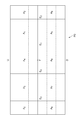
- FIG. 2 shows an equidistant cylindrical image P0 including a scene to be projected onto the sphere S.
- the scene projected on the surface of the sphere S is converted into a rectangular equidistant cylindrical image P0 of aspect ratio 1: 2 so that the positional relationship between upper, lower, left, and right viewed from the observation point is maintained. .
- the parallels of the spheres S extend parallel to each other along the lateral direction, the meridians extend parallel to one another along the vertical direction, and all the parallels are perpendicular to the meridians.
- the divided areas A 1 to A 8 are converted into square areas, the entire upper side of the equidistant cylindrical image P 0 corresponds to the point U, and the entire lower side corresponds to the point D.
- a region (region of high latitude) located in the vicinity of the point U and the point D on the surface of the sphere S is stretched in the left-right direction in the equidistant cylindrical image P0. Therefore, in the vicinity of the upper side and the lower side of the equidistant cylindrical image P0, the amount of information contained in a unit pixel is reduced as compared with the low latitude region in the middle of the image.
- FIG. 3 shows a first panoramic image P1 including the scene to be projected onto the sphere S.
- the first panoramic image P1 has a square shape as a whole.
- the center point of the square corresponds to the point D
- the point U on the sphere S opposite to the point D corresponds to the four corners of the square. That is, the four vertices of the first panoramic image P1 correspond to one point U on the sphere S.
- the midpoint of the lower side is the point E 3, the left side of the midpoint to point E 4, respectively correspond.
- the upper right vertex is point U 1
- the lower right vertex is point U 2
- the lower left vertex is point U 3
- the apex of the upper left is a point U 4.
- the parallel line of ⁇ ⁇ 0 is bent by 90 degrees at a position intersecting each of the straight line E 1 D, the straight line E 2 D, the straight line E 3 D, and the straight line E 4 D in the first panoramic image P1.
- the parallel line of ⁇ > 0 is four squares E 1 U 1 E 2 D, square DE 2 U 2 E 3, square U 4 E 1 DE 4 , and squares formed by dividing the first panoramic image P 1 into four.
- E 4 DE 3 U 3 is divided into each.
- These four squares correspond to four regions obtained by dividing the surface of the sphere S into four by two vertical planes orthogonal to each other. And, inside each of these squares, parallels (that is, a line of intersection between a plane perpendicular to two vertical planes and the sphere S) are arranged side by side in parallel with the diagonal of the square.
- Each of divided areas A 1 to A 8 obtained by dividing the surface of the sphere S into eight is converted into an area having a right isosceles triangle shape in the first panoramic image P1.
- each divided area is converted to a shape relatively similar to the shape on the original spherical surface as compared with the equidistant cylindrical image P0 converted to the square shape. Therefore, the difference in the amount of information contained per unit pixel between the high latitude region and the low latitude region becomes smaller compared to the equidistant cylindrical image P0.
- an area in the panoramic image P obtained by converting each divided area is referred to as a conversion area.
- position coordinates in the first panoramic image P1 are represented by an orthogonal coordinate system in which the horizontal direction is the x axis, the vertical direction is the y axis, and the center position is the origin.
- the latitude ⁇ and the longitude ⁇ on the surface of the sphere S are expressed by the following equation using variables u, v and a.
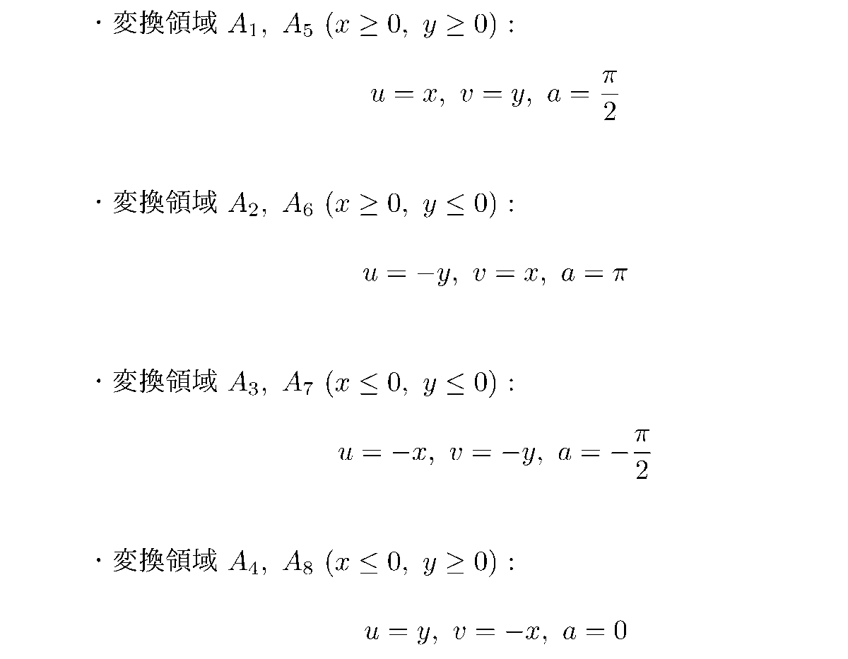
- the variables u, v, a are respectively expressed by the following equations according to the position coordinates (x, y) in the first panoramic image P1.
- the correspondence between the position on the sphere S and the position in the first panoramic image P1 is defined by these mathematical expressions.
- the latitude ⁇ is in a linear relationship with each of x and y in each divided area.
- the coordinates correspond one to one.
- adjacent pixels in the first panoramic image P1 also correspond to areas adjacent to each other in the sphere S. That is, although there are places where the parallel lines and meridians bend in the first panoramic image P1, conversion is not performed such that discontinuous regions separated from each other on the sphere S are adjacent in the first panoramic image P1.
- the point on the outer periphery of the first panoramic image P1 is continuous on the sphere S with the location on the same side corresponding to the case where each side of the square is folded at the middle point.
- the n-th pixel from the left end and the n-th pixel from the right end correspond to mutually adjacent areas on the sphere S.
- the amount of information per unit pixel is the largest in the low latitude region (region in the middle of the image).
- the number of pixels in the vertical direction Equirectangular image P0 and 2N (ranging from for example the point E 1 to point E 2) the number of pixels in the horizontal direction is 4N, and the field of view of 90 degrees in the horizontal plane
- the number of pixels corresponding to n is N.
- the pixels corresponding to the field of view range of 90 degrees on the ground plane are oblique as shown by straight line E 1 E 2 in FIG.
- the first panoramic image P1 can obtain substantially the same image quality in the low latitude region as compared with the regular distance cylindrical image P0 having the same number of pixels in the vertical direction.
- the number of pixels corresponding to this visual field range in the equidistant cylindrical image P0 is , And the number of pixels 2N in the vertical direction of the image.
- the field of view corresponds to a path from the point D through the point E 1 from the point U 1 of FIG.
- the number of pixels of one side of the first panorama image P1 The number of pixels 2N minus 1 (2N-1).
- 1 is reduced because the pixel at the point E 1 is also an end point of the straight line U 1 E 1 and an end point of the straight line E 1 D and is shared by both.
- the first panoramic image P1 has almost the same resolution as the equidistant cylindrical image P0 having the same number of pixels in the vertical direction. It is understood that it can be obtained.
- the first panoramic image P1 Although the number of pixels in the first panoramic image P1 decreases as the latitude becomes higher, since the high latitude region of the equidistant cylindrical image P0 originally has a large waste of information, the first panoramic image P1 is an equidistant cylindrical image even in the high latitude region There is almost no deterioration in image quality compared to P0. That is, the first panoramic image P1 has an image quality that is comparable to that of the regular-distance cylindrical image P0 having the same number of pixels in the vertical direction over the entire sky.
- the first panoramic image P1 can obtain almost the same image quality as the regular-distance cylindrical image P0 with a total of just half the number of pixels. From this, if the first panoramic image P1 is used, the data size can be made smaller compared to the equidistant cylindrical image P0 without any loss in image quality. Further, it is possible to realize high resolution of the image without enlarging the data size of the image as compared with the regular distance cylindrical image P0.
- image data including two panoramic images for left eye and right eye can be provided with the same number of pixels as that of one regular distance cylindrical image P0.
- the panoramic image P according to the second example is referred to as a second panoramic image P2.
- a second panoramic image P2 when converting the position on the sphere S to a position in the second panoramic image P2, different coordinate systems are used for two hemispherical surfaces obtained by dividing the surface of the sphere S into two. Do the conversion.
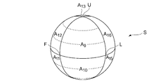
- the definition of the position coordinates on the sphere S in the second example will be described with reference to FIGS. 4A to 4D.
- FIG. 4A is a perspective view of the ball S as viewed from the front upper side
- FIG. 4B is a perspective view of the ball S as viewed from the rear lower side
- 4C is a front view
- FIG. 4D is a rear view
- the position of point F is the front direction.
- a point corresponding to the zenith is a point U
- a point corresponding to the nasol is a point D.
- four points separated by 90 degrees on the ground plane are set as a point F, a point L, a point B, and a point R.
- the observer at the center point (observation point) of the sphere S faces the direction (front direction) of point F
- the right hand direction is point R
- the back direction is point B
- the left hand direction is point L.
- the position coordinates are defined by the latitude ⁇ and the longitude ⁇ similar to the first example described above. That is, the parallels are parallel to the ground plane, and the meridians are the circumference of the great circle of the sphere S passing through the points U and D.
- the hemispherical surface on the front side half of the sphere S is referred to as a front region, and a coordinate system indicating the position in the front region is referred to as a front coordinate system.
- FIG. 4A and FIG. 4C several parallels in the front area are indicated by broken lines.
- the direction toward is the positive direction of longitude ⁇ .
- the latitude ⁇ and the longitude ⁇ are defined in directions different from the front area. Specifically, the latitude ⁇ and the longitude ⁇ are defined in the same direction as the earth when the point L is regarded as the north pole and the point R is regarded as the south pole.
- the latitude is the outer periphery of the cross section of the sphere S perpendicular to the straight line LR, and the meridian is the circumference of the great circle of the sphere S passing the points L and R.
- the back surface area the hemispherical surface on the back side half of the sphere S
- the coordinate system indicating the position in the back surface area is referred to as the back surface coordinate system.
- FIGS. 4B and 4D several parallels in the back surface area defined by the back surface coordinate system are indicated by alternate long and short dash lines.
- the parallel lines extend parallel to the straight line UD (that is, in the direction orthogonal to the parallel lines of the front surface coordinate system) when viewed from the back surface side.
- the point U, the point L, the point D, and the point R located on the boundary between the front area and the back area are represented in position coordinates different from the front coordinate system in the back surface coordinate system.
- regions A 9 to A 16 eight regions obtained by dividing the surface of the sphere S by three planes orthogonal to one another are denoted as divided regions A 9 to A 16 .
- the three planes orthogonal to each other are a ground plane including point F, point L, point B, and point R, a vertical plane including point U, point F, point D, and point B, point U, It is a vertical plane including point L, point D, and point R.
- a 13 be an area surrounded by points D, B, and R be a divided area A 14 , an area surrounded by points D, L, and B be a divided area A 15 , a point U, a point B, the region surrounded by points L and divided area a 16.
- These divided areas A 9 to A 16 are areas surrounded by three parallel lines or meridians each having a length corresponding to 1 ⁇ 4 of the circumference of the great circle of the sphere S, and have mutually equal sizes Size and shape.
- FIG. 5 shows a second panoramic image P2 including the scene to be projected onto the sphere S.
- the second panoramic image P2 also has a square shape as a whole, similarly to the first panoramic image P1.
- the center point of the square corresponds to the point F
- the point B on the sphere S opposite to the point F corresponds to the four corners of the square. That is, four vertices of the second panoramic image P2 correspond to one point B on the sphere S.
- the middle point of the left side of the square corresponds to the point L, the middle point of the upper side to the point U, the middle point of the right side to the point R, and the middle point of the lower side to the point D.
- the top right vertex is the point B 1
- the bottom right vertex is the point B 2
- the bottom left vertex is the point B 3
- the top left vertex is the point B 4 .
- the front area of the sphere S is converted into the square RULD in FIG.
- the parallels are parallel to one another along the left-right direction (the direction parallel to the straight line LR).
- the meridians extend radially from point U, bend at a position intersecting straight line RL and extend to point D.
- the back surface area of the sphere S is divided into four and converted into right-angled isosceles triangular conversion areas, and arranged outside the square RULD.
- the arrangement position of each conversion area is determined so that the continuous area on the sphere S is adjacent also in the second panoramic image P2. That is, in the second panoramic image P2, similarly to the first panoramic image P1, divided regions A 9 to A 16 obtained by dividing the surface of the sphere S into eight are respectively converted regions A 9 to It is converted to A 16 and arranged so as to maintain the adjacent relation on the sphere S to form a square panoramic image.
- the parallel lines of the back surface coordinate system are arranged parallel to one another along the direction parallel to the straight line LR like the parallel lines of the front surface coordinate system.
- position coordinates in the second panoramic image P2 are represented by an orthogonal coordinate system in which the horizontal direction is an x axis, the vertical direction is a y axis, and the center position is an origin.
- the latitude ⁇ and the longitude ⁇ on the surface of the sphere S are expressed by the following equation using variables u and v.
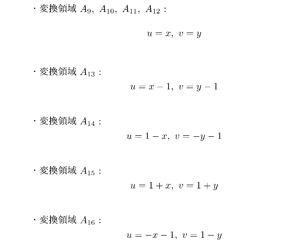
- the variables u and v are represented by the following equations according to the position coordinates (x, y) in the second panoramic image P2, respectively.
- the correspondence relationship between the position on the sphere S and the position in the second panoramic image P2 is defined by these mathematical expressions.
- the latitude ⁇ and the longitude ⁇ in the front area are defined by the front coordinate system
- the latitude ⁇ and the longitude ⁇ in the rear area are defined by the back coordinate system.
- the latitude ⁇ has a linear relationship with each of x and y in each divided area.
- the coordinates correspond one to one.
- adjacent pixels in the second panoramic image P2 also correspond to regions adjacent to each other in the sphere S.
- the point on the outer periphery of the second panoramic image P2 is continuous on the sphere S with the location on the same side corresponding to the case where each side of the square is folded at the middle point.
- the second panoramic image P2 can realize an image quality substantially equal to that of the regular-distance cylindrical image P0 with half the number of pixels of the regular-distance cylindrical image P0.
- the second side of the panoramic view (the scene projected on the hemispherical surface centered on the point F) viewed from the observer is not divided. It is converted into a square whose center coincides with the image P2. Therefore, the use of the second panoramic image P2 is suitable, particularly when presenting the user with a view ahead of the rear.
- the point D is disposed at the center and the opposing point U corresponds to the vertex of the four corners
- the point F is disposed at the center
- the opposite point B correspond to the vertices of the four corners. That is, there is a difference in the direction of conversion when converting both the sphere S into the planar panoramic image P.
- the contents of the conversion itself are similar between the two. Specifically, in each case, eight divided areas on the spherical surface divided by three planes orthogonal to each other through the center of the sphere S are respectively converted into transformation areas in the form of a right isosceles triangle. There is. Thereby, the difference in the amount of information between pixels can be reduced.
- each divided area is converted into a right-angled isosceles triangle because a panoramic image P can be made into a square shape by arranging and arranging eight right-angled isosceles triangles. If it is permitted to make the shape of the panoramic image P into another (for example, rectangular) shape, even if each divided area is converted to a triangle (such as a right triangle) which is not a right isosceles triangle, the equidistant cylindrical image It is possible to reduce the difference in the amount of information between pixels compared to P0.
- the panoramic image P according to the third example is referred to as a third panoramic image P3.
- the surface of the sphere S is divided into eight areas of divided areas A 9 to A 16 as in the second example.
- position coordinates on the sphere S are represented by latitude ⁇ and longitude ⁇ defined similarly to the frontal coordinate system in the second example. That is, unlike the second example, in the third example, the position on the surface of the sphere S is represented by a single coordinate system over the entire surface of the sphere S.
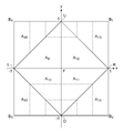
- FIG. 6 shows a third panoramic image P3 including the scene to be projected onto the sphere S.
- the third panoramic image P3 eight divided areas A 9 to A 16 are respectively converted into right-angled isosceles triangles in the same manner as the second panoramic image P2, and the second panoramic image It is arranged at the same position as P2.
- the divided areas A 9 to A 12 are converted into converted areas A 9 to A 12 in the third panoramic image P 3 by the same conversion equation as the second panoramic image P 2. That is, when expressing the same scenery, the image data in the square URDL will match between the second panoramic image P2 and the third panoramic image P3.
- the divided areas A 13 to A 16 are converted into the converted area of the same position and shape as the second panoramic image P 2 in the third panoramic image P 3, but the position in the divided area is the second panoramic image P 2 Is converted to a position in the corresponding conversion area by a conversion formula different from.
- the parallel line of ⁇ > 0 is U-shaped opened upward as shown by the dotted line in the drawing.
- the parallel line of ⁇ ⁇ 0 is U-shaped opened downward.
- position coordinates in the third panoramic image P3 are represented by an orthogonal coordinate system having the horizontal direction as the x axis, the vertical direction as the y axis, and the center position as the origin.
- the latitude ⁇ and the longitude ⁇ on the surface of the sphere S are expressed by the following equation using variables u, v and a.
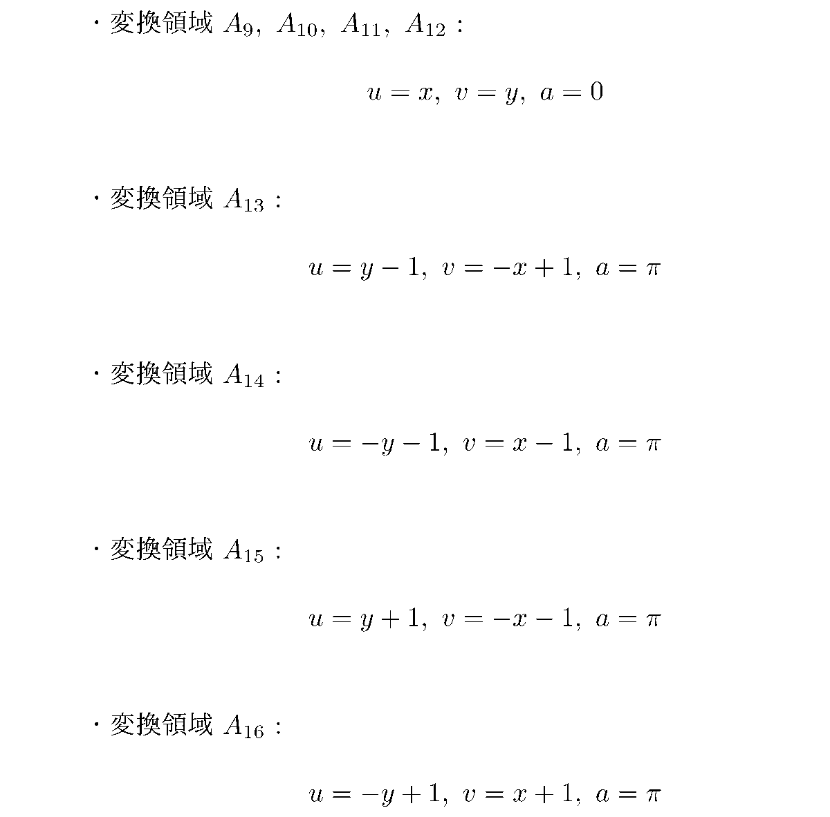
- the variables u, v, a are respectively expressed by the following equations according to the position coordinates (x, y) in the third panoramic image P3.
- These equations define the correspondence between the position on the sphere S and the position in the third panoramic image P3.
- the latitude ⁇ has a linear relationship with each of x and y in each divided area.
- the view on the front side (the view projected on the hemispherical surface centered at the point F) viewed from the observer is not divided but the third panoramic image
- the square URDL in P3 has been converted. Therefore, as compared with the first example, it is suitable for an application that presents the user with the forward scene.
- the entire sphere S is defined by one coordinate system, and there is no need to exchange latitude and longitude, the equidistant cylindrical image P0 is converted into a panoramic image P as compared with the second example.
- the sphere S is divided by the vertical plane including the point U, the point E 1 , the point D, and the point E 3 and the vertical plane including the point U 2 , the point E 2 , the point D, and the point E 4
- the resulting four regions are transformed into four squares E 1 U 1 E 2 D, squares DE 2 U 2 E 3, squares U 4 E 1 DE 4 , and squares E 4 DE 3 U 3 .
- a circumference obtained by making the remaining one plane orthogonal to the sphere S among the three planes described above is converted into the diagonal lines of the four squares.
- the diagonals of the four squares mentioned above, square E 1 E 2 E 3 E 4 corresponding to the ground plane is formed. That is, each of the first panoramic image P1, the second panoramic image P2, and the third panoramic image P3 is made into four squares by combining eight right isosceles triangles into two, and these four squares are The base of each right-angled isosceles triangle is arranged by arranging in 2 rows and 2 columns so as to form a square.
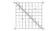
- FIG. 7 is a view showing an example of a square formed by combining two right-angled isosceles triangular transformation regions in the embodiment described above, and is a square E 1 in the first panoramic image P1 of FIG.
- the pixel arrangement of U 1 E 2 D is shown.
- one side of the square is formed of eight pixels.
- the number of diagonally arranged pixels is also eight.
- diagonal pixels are indicated by hatching.
- one right-angled isosceles triangle is configured by N (N + 1) / 2 pixels, where N is the number of pixels at the base. If this is simply doubled, it becomes N (N + 1). That is, when it is desired to set the number of pixels of the base of each right-angled isosceles triangle to N, a rectangular area of N rows (N + 1) is required for two right-angled isosceles triangles.
- the base is shared between two right isosceles triangles. That is, the pixels on one diagonal of the square constitute the base of each of the two right-angled isosceles triangular transformation regions.
- a rectangle formed by combining two right isosceles triangles is just a square of N rows and N columns.
- the entire panoramic image P also has the number of pixels in the vertical direction and the horizontal direction. It becomes a square where the number of pixels is equal. With such a configuration, processing such as video compression is facilitated.
- the N rows and N columns are configured by arranging (2N-1) pixel columns composed of a plurality of pixels arranged along a straight line parallel to the straight line E 1 E 2 from the upper right to the lower left It can be regarded as That is, the upper right pixel closest to the point U 1 alone constitutes the first pixel row.
- the pixel on the left of the pixel at the upper right and the two pixels at the pixel immediately below constitute a second pixel row.
- N-th pixel row is indicated by hatching in FIG. 7 is constituted by N pixels from the point E 1 to point E 2.
- the (N + 1) -th pixel column is constituted by (N-1) pixels positioned to the left of the hatched pixels in FIG.
- the (2N-1) -th pixel column is constituted by the lower left pixel closest to the point D.
- N the number of pixels in the square of N rows and N columns in total.
- a straight line parallel to the straight line E 1 E 2 corresponds to a parallel line on the sphere S. Therefore, each pixel belonging to the same pixel column corresponds to the area of the same latitude on the sphere S.
- the 180 ° visual field range from the zenith to the zenith of the sphere S is converted into (2N-1) pixel rows in the first panoramic image P1.
- the latitude ⁇ is in a linear relationship with x and y in the conversion equation for converting the point on the sphere S and the point in the first panoramic image P1. Therefore, the (2N-1) pixel columns described above correspond to mutually equal latitude ranges on the sphere S.
- each pixel row corresponds to a band-like region on the sphere S corresponding to the latitude range of ⁇ / (2N-1). Furthermore, according to the conversion equation described above, the pixels included in the same pixel row correspond to the same wide region in the band-like region on the sphere S. That is, the pixels included in the pixel row corresponding to the area of the same latitude have the same amount of information. Also in the second panoramic image P2 and the third panoramic image P3, although the orientation of the pixel array is different, the feature relating to conversion between such a divided area and a conversion area holds in the same manner.
- the view of the divided area on the sphere is simply projected as it is on the internal plane of the sphere.
- the difference in the information amount of each pixel in the panoramic image P is smaller.
- the panoramic image P in the present embodiment is not limited to this, and various coordinate systems used for conversion, various arrangements of the conversion areas in the panoramic image P, and the like are changed. There may be variations. In any case, eight divided areas obtained by dividing the surface of the sphere S by three planes orthogonal to each other passing through the center of the sphere S are respectively converted into triangular transformation areas, By arranging at, it is possible to generate a square-shaped panoramic image P including the landscape of the whole sky.
- the square panoramic image P having the same number of pixels in the vertical direction and the number of pixels in the horizontal direction is generated by converting the divided areas on the sphere S into triangular areas and arranging them on a plane.
- the panoramic image P in the present embodiment is not limited to such.
- the two divided areas may be converted into right isosceles triangle-shaped areas whose base is a pixel row consisting of N pixels without sharing the base.
- a 1/4 area of the sphere S is converted to a rectangular area of N rows (N + 1) columns, and the panoramic image P has a rectangular shape of 2N rows (2N + 2) columns in total.
- the 1 ⁇ 4 region of the sphere S may be converted into a rectangular region of N rows (N + m) columns.
- N is a natural number of 1 or more.
- m is a natural number of 1 or more.
- FIG. 8 shows an example of an N-row (N + m) -column rectangle obtained by converting 1 ⁇ 4 of the surface of the sphere S in this example.
- the area (the divided areas A 1 and A 5 ) of the sphere S corresponding to the square E 1 U 1 E 2 D in the first panoramic image P 1 of FIG. 3 is converted by the conversion method similar to the first panoramic image P 1
- the divided area on the sphere S is converted into a trapezoidal shape, not the triangular shape as in the previous embodiments.
- the same number of labels are given to the pixel groups corresponding to the area of the same latitude on the sphere S.
- a group of pixels whose latitudes on the corresponding sphere S are equal to each other is referred to as a co-latitude pixel group.
- the pixels to which the same label is given in FIG. 8 belong to the same same latitude pixel group. For example, the upper right pixel labeled “1” in FIG.
- each same latitude pixel group forms a strip-like pixel row along a diagonal line from upper left to lower right.
- the same latitude pixel group of the label "8" to the label "11" corresponding to the relatively low latitude region is constituted by the largest number of pixels, and the same latitude pixel group is closer to the point U or the point D from there
- the number of pixels that make up is decreasing.
- the number of pixels expressing the range of 90 degrees along the ground plane is N as in the example of FIG. 7, but from point U 1 to point E 1 or point E 2
- the number of pixels representing the range of 180 degrees to reach the point is (2N-1 + m) with respect to (2N-1) in FIG.
- the resolution of expressing the vertical direction of the sphere S is improved as the shape of the panoramic image P is changed from square to rectangular and the number of pixels in the horizontal direction is increased.
- the panoramic image P has a shape stretched in the left-right direction, but may have a shape stretched in the vertical direction.
- FIG. 9 shows another example of forming the panoramic image P in a rectangular shape.
- an example is shown in which the area corresponding to the square UFRB 1 in FIG. 6 is converted into a rectangle by a conversion method similar to that of the third panoramic image P3.
- labels belonging to the same numeral are assigned to pixels belonging to the same same latitude pixel group.
- the third panoramic image P 3 among the conversion areas A 12 and A 13 corresponding to 1 ⁇ 4 of the surface of the sphere S, the upper left corresponds to the area of the same latitude closest to the point U,
- four (i.e., 1 + m) pixels to which the label "1" is attached form a high-latitude same-latitude pixel group closest to the point U.
- the same latitude pixel group of label "8" corresponds to the area along the ground plane, and is constituted by (2N-1 + m) pixels. That is, in FIG. 9, the range of 90 degrees in the vertical direction of the sphere S is represented by N pixels, and the range of 180 degrees in the horizontal direction is represented by (2N-1 + m) pixels. Conversely, the resolution in the left-right direction is improved.
- the same latitude pixel group forms an L-shaped area as in the case of the third panoramic image P.
- the divided regions A 13 are members is converted to the same right-angled isosceles triangle and the third panoramic image P3, divided area A 12 is converted into a trapezoidal shape.
- the resolution in the vertical direction or horizontal direction can be improved as compared to the case where it is made square.
- the same latitude pixel group corresponding to the parallel line on the sphere S forms a band-like region in the panoramic image P.
- the parallels are a set of points on the sphere S having equal distances from a certain point (hereinafter referred to as an extreme point).
- the pole points are the point U and the point D
- the parallel line is a plane parallel to the ground plane on the sphere S It corresponds to the intersection line with the sphere S surface.
- the points R and L are poles, and the parallels extend along the vertical direction as indicated by the dashed dotted line in FIG. 4D.
- the panoramic image P in the present embodiment when focusing on an arbitrary parallel line on the sphere S, the same latitude pixel corresponding to the parallel line
- the number of pixels belonging to the group is equal to or less than the number of pixels belonging to the same latitude pixel group corresponding to the parallel line lower in latitude than the parallel line (ie, the parallel line closer to the pole).
- the number of pixels included in the same latitude pixel group decreases as the latitude increases.
- the number of pixels belonging to the same latitude pixel group is constant regardless of the latitude.
- the number of pixels belonging to the same latitude pixel group corresponding to high latitude parallel lines is smaller than the number of pixels in the same latitude pixel group corresponding to low latitude parallel lines.
- the panoramic image P in the present embodiment is not limited to this.
- the panoramic image P does not include all of the eight conversion areas corresponding to eight division areas obtained by dividing the surface of the sphere S, but may include only a partial conversion area. Good.
- the panoramic image P does not include all of the eight conversion areas corresponding to eight division areas obtained by dividing the surface of the sphere S, but may include only a partial conversion area.
- the panoramic image P does not include all of the eight conversion areas corresponding to eight division areas obtained by dividing the surface of the sphere S, but may include only a partial conversion area.
- Good For example, among eight divided areas obtained by dividing the surface of the sphere S shown in FIGS. 4A to 4D, only four divided areas A 9 to A 12 are converted into conversion areas and arranged on a plane, It may be a panoramic image P. This makes it possible to obtain a panoramic image P that includes only the scenery in the hemisphere ahead of the observation point.
- the panoramic image P in this case may be equivalent to a square RULD which is a part of the second panoramic image P2 shown in FIG.
- the four divided areas may be arranged to form a rectangle instead of a square.
- two divided areas are converted into a conversion area of a right-angled isosceles triangle to form a square panoramic image P as illustrated in FIG. You may
- the panoramic image P in the present embodiment does not project the view seen from the observation point onto the whole of the sphere S, but projects the view only to a part of the range, and divides the sphere S on which the scenery is projected. It may be formed by converting at least one of the eight divided areas obtained by In this example, a scene may be projected to a partial area of one divided area, and the divided area may be converted to a conversion area in a state where a scene is not projected to the other area. In that case, the range in which the view is not projected may be converted into a pixel having dummy information (for example, a pixel having a pixel value of 0) in the panoramic image P. As a result, even if there is no information on the scenery in a partial range, such as a high latitude range close to the nadir, for example, the panoramic image P can be generated by the method of the present embodiment.
- the high latitude range near the zenith or the zenith is a rectangular shape near the points U and D. It becomes an area.
- the panoramic image P obtained by converting the range of the sphere S excluding the portion can be rearranged into a rectangle.
- the arrangement of pixel rows corresponding to each parallel line in this case is similar to that illustrated in FIG.
- the latitude ⁇ which is the position coordinates of the surface of the sphere S, is in a linear relationship with the position coordinates x, y in the panoramic image P.
- the latitude range of 180 degrees is converted into 18 equal latitude pixel groups.
- the same latitude pixel group corresponds to an angle of 10 degrees of latitude.
- the same latitude pixel group to which the label "1" is assigned corresponds to the range of 80 degrees to 90 degrees on the sphere S
- the same latitude pixel group to which the label "2" is assigned is the latitude on the sphere S
- the same latitude pixel group to which the label "18" is attached corresponds to the range of 70 degrees to 80 degrees and corresponds to the range of latitude -80 degrees to -90 degrees.
- the pixels belonging to the same same latitude pixel group correspond to the same longitude range.
- the panoramic image P in the present embodiment is not limited to this, and the latitude range and the longitude range corresponding to each pixel may be made different from each other.
- the latitude range and the longitude range on the sphere S corresponding to the pixels in the panoramic image P should be narrower than other areas. It is also good.
- the resolution of the important area can be made higher than the other areas. As an example, it is considered that the user is more likely to focus on low latitude areas (areas closer to the ground plane) than high latitude areas (areas close to the zenith or the zenith).
- the latitude range per pixel group in the same latitude is 45 degrees or more and 45 degrees or less in the same latitude pixel group.
- Half of the latitude range In this way, the attention range corresponding to half of the 180 degree latitude range can be made to have a resolution twice that of the other range.
- the corresponding latitude range for each pixel is changed in two steps, it is not limited to this and may be changed in more steps.
- the corresponding longitude range may be changed in the same manner as the latitude range.
- the method of making the corresponding latitude range and the corresponding longitude range per unit pixel different as described above can be applied not only to the panoramic image P in the present embodiment but also to the equidistant cylindrical image P0.
- the image generation device 10 is an information processing device that generates a panoramic image P, and may be, for example, a home game machine, a portable game machine, a personal computer, a smartphone, a tablet, or the like. As shown in FIG. 10, the image generation apparatus 10 includes a control unit 11, a storage unit 12, and a communication unit 13.
- the control unit 11 includes at least one processor such as a CPU, and executes a program stored in the storage unit 12 to execute various information processing. In particular, in the present embodiment, the control unit 11 executes a process of generating a panoramic image P.
- the storage unit 12 includes at least one memory device such as a RAM, and stores a program executed by the control unit 11 and data processed by the program.
- the communication unit 13 is a communication interface such as a LAN card, and transmits data of the panoramic image P to the image display control device 20 via a communication network.
- the image display control device 20 is an information processing device that performs display control of an image based on the panoramic image P generated by the image generation device 10, and like the image generation device 10, a home game machine, a portable game machine , A personal computer, a smartphone, a tablet or the like.
- the image display control device 20 includes a control unit 21, a storage unit 22, and a communication unit 23. Furthermore, the image display control device 20 is connected to the display device 24 and the operation device 25.
- the control unit 21 includes at least one processor such as a CPU, and executes a program stored in the storage unit 22 to execute various information processing. In particular, in the present embodiment, the control unit 21 executes a process of drawing a display image based on the panoramic image P.
- the storage unit 22 includes at least one memory device such as a RAM, and stores a program executed by the control unit 21 and data processed by the program.
- the communication unit 23 is a communication interface such as a LAN card, and receives data transmitted from the image generation apparatus 10 via the communication network.
- the display device 24 is a liquid crystal display or the like, and displays an image according to a video signal supplied by the image display control device 20.
- the display device 24 may be a stereoscopic image display device that displays a stereoscopic viewable image supplied by the image display control device 20.
- the display device 24 may be a head-mounted display device such as a head-mounted display that can be worn by the user on the head.
- the operation device 25 is a controller of a home-use game machine, a pointing device, or the like, and is used by the user to perform various instruction operations on the image generation apparatus 10.
- the content of the user's operation input to the operation device 25 is transmitted to the image display control device 20 by either wire or wireless.
- the operation device 25 may include an operation button or a touch panel disposed on the surface of the case of the image display control device 20.
- the image generation apparatus 10 functionally includes a landscape information acquisition unit 31 and a panoramic image generation unit 32. These functions are realized by the control unit 11 executing a program stored in the storage unit 12. Further, the image display control device 20 functionally includes a panoramic image acquisition unit 33, a direction acquisition unit 34, and a display image drawing unit 35. These functions are realized by the control unit 21 executing a program stored in the storage unit 22.
- the program executed by each device may be provided to each device via a communication network such as the Internet, or may be provided by being stored in a computer-readable information storage medium such as an optical disk.
- the scenery information acquisition unit 31 acquires scenery information as original data for generating a panoramic image P.
- the landscape information is information necessary to specify the color (pixel value) of each unit area on the surface of the sphere S when the panoramic view seen from the observation point is projected onto the virtual sphere S. is there.
- the landscape information may be a panoramic image generated in an image format different from that of the present embodiment, such as equidistant cylindrical projection.
- it may be image data of a panoramic picture taken by a panoramic camera.
- the scenery information acquisition unit 31 may receive scenery information from another device via a communication network, or may read it from a device such as a camera connected to the image generation device 10.
- the scene information stored in an information storage medium such as a flash memory may also be read.
- the panoramic image generation unit 32 generates a panoramic image P using the view information acquired by the view information acquisition unit 31.
- the panoramic image P is two-dimensional image data on which the scenery of the entire sky (or a part thereof) is projected as described above.
- the panoramic image generation unit 32 uses the pixel value of each pixel in the panoramic image P as the scene information according to the above-described calculation formula indicating the correspondence between the point on the sphere S and the point in the panoramic image P.
- the panoramic image P is generated by calculating based on the above.
- the panoramic image generation unit 32 may generate image data for stereoscopic vision.
- the image data generated in this case includes, for example, a square panoramic image P for generating a left-eye image in the left half, and a horizontal and vertical image including a square panoramic image P for generating a right-eye image in the right half. It may be rectangular image data with a ratio of 1: 2.
- the panoramic image generation unit 32 may generate the panoramic image P as a moving image that changes with time.
- the panoramic image generation unit 32 selects one image format from a plurality of types of image formats such as the first panoramic image P1 and the second panoramic image P2 described above, and the panoramic image P is selected according to the selected image format. It may be generated. In this case, the panoramic image generation unit 32 outputs the information specifying the image format of the generated panoramic image P together with the panoramic image P.
- the panoramic image acquisition unit 33 acquires the panoramic image P generated by the panoramic image generation unit 32 of the image generation device 10.
- the panoramic image acquisition unit 33 directly receives the panoramic image P transmitted from the image generation apparatus 10 via the communication network.
- the present invention is not limited to this, and the panoramic image acquisition unit 33 may receive the panoramic image P via another device such as a server computer.
- the panoramic image P temporarily stored in an information storage medium such as a flash memory may be read out and acquired from this information storage medium.
- the direction acquisition unit 34 acquires direction information used to determine the visual field range (display range) of the display image displayed on the display device 24 based on the user's instruction or the like.
- the direction information acquired by the direction acquiring unit 34 is used as an imaging direction of a virtual camera when a display image drawing unit 35 described later generates a display image.
- the imaging direction is defined by, for example, a yaw angle representing an angle in the horizontal direction and a pitch angle representing an angle in the vertical direction.
- the direction acquisition unit 34 may also acquire a roll angle indicating the angle of rotation of the camera with the imaging direction as the rotation axis.
- the direction acquisition unit 34 acquires direction information by receiving an operation input that indicates the direction of the user with respect to the operation device 25.
- the direction acquisition unit 34 may acquire direction information from the detection result of the motion sensor incorporated in the image display control device 20 when the user performs an operation of tilting the main body of the image display control device 20.
- the image display control device 20 is provided with a small housing such as a smartphone or a tablet
- the user changes the view range to an arbitrary direction by changing the direction of the image display control device 20.
- the direction acquisition unit 34 may acquire direction information from the detection result of the motion sensor incorporated in the display device 24.
- the visual field range can be changed according to the change in the orientation of the head of the user.
- the display image drawing unit 35 draws a display image showing a view within the view range determined according to the direction information acquired by the direction acquisition unit 34 based on the panoramic image P acquired by the panoramic image acquisition unit 33, and displays the display device Display on 24 Thereby, the user can browse the scenery within the specific visual field included in the panoramic image P. Furthermore, by changing the visual field range by an operation input to the operation device 25 or the like, it is possible to browse the scenery in any direction of the entire sky.
- the display image drawing unit 35 arranges the sphere S in the virtual space, and arranges the virtual camera at the center position of the sphere S. At this time, the virtual camera is disposed with an orientation and an inclination determined according to the direction information acquired by the direction acquiring unit 34. Furthermore, the display image drawing unit 35 pastes a texture generated based on the panoramic image P on the inner surface of the sphere S, and draws a view of the inner surface of the sphere S to which the texture is pasted from a virtual camera. , To generate a display image. When generating the texture to be attached to the sphere S, the display image drawing unit 35 is determined according to the specified image format with reference to the information specifying the image format output together with the panoramic image P. According to the formula, the pixel in the panoramic image P corresponding to each pixel included in the texture is identified.
- each point on the sphere S corresponds to one point in the panoramic image P. Therefore, when determining the pixel value (color) of the pixel (texel) included in the texture, the pixel value of the pixel in the panoramic image P corresponding to the position on the sphere S to which the texel is pasted is referenced. However, due to differences in resolution and shape, etc., the texels in the texture and the pixels in the panoramic image P do not correspond one to one.
- the display image drawing unit 35 converts the position on the sphere S of texels into a position (here, point X) in the panoramic image P, and determines a plurality of pixels near the point X as sampling targets. Then, the pixel value of the texel is determined by executing interpolation processing using the pixel value of the pixel to be sampled.
- the horizontal and vertical directions of the image do not necessarily coincide with the horizontal and vertical directions of the sphere S.
- the horizontal direction (the direction of the parallels) of the sphere S in any conversion region corresponds to a direction inclined 45 degrees with respect to the horizontal direction of the image.
- the display image drawing unit 35 selects pixels to be sampled in accordance with the type of the image format of the panoramic image P and the selection rule defined for each conversion area in the image.
- parallels connecting the equal latitude as indicated by the broken line in FIG. 3 is a straight line of left-side up at an angle in the horizontal direction and 45 degrees ing.
- the display image drawing unit 35 targets four pixels X 1 to X 4 arranged along two parallel lines near the point X as shown in FIG. Choose as.
- a set of pixels X 1 and the pixel X 2 and latitude set of corresponding respective pixels X 3 and the pixel X 4 becomes equal combination with one another.
- the display image drawing unit 35 obtains the interpolated values I1 corresponding to the fraction of the longitude of the point X from the pixel value of the pixel X 1 pixel X 2. Moreover, to obtain an interpolated value I2 corresponding to the fraction of the longitude of the point X from the pixel values of the pixels X 3 and the pixel X 4. In addition, since the value of the longitude of each pixel is different, coefficients for calculating the interpolation value I1 and for calculating the interpolation value I2 are different from each other.
- the pixel value of the texel corresponding to the point X is determined by calculating the interpolation value according to the fraction of the latitude of the point X from the interpolation value I1 and the interpolation value I2.
- the pixel value of each texel included in the texture attached to the inner surface of the sphere S is calculated.
- the sampling pixel row may be arranged along the outer periphery of the panoramic image P.
- the sampling pixel row is a pixel row obtained by inverting the pixel row on one side of the panoramic image P horizontally or vertically, and is arranged to be adjacent to the pixel row to be inverted.
- FIG. 13 shows an example of a panoramic image P to which a sampling pixel row is added.
- a panoramic image P is shown in which sampling pixel columns are added one by one above and below the third panoramic image P3 having a square shape of 16 rows and 16 columns.
- the sampling pixel row is indicated by hatching.
- pixels given the same Greek letter or lower case alphabetic label have the same pixel value.
- the sampling pixel row at the top of the figure is a pixel row obtained by inverting the left and right pixel rows from the top, and the sampling pixel row at the bottom is 2 from the bottom. It is a pixel row obtained by horizontally inverting the pixel row of the stage.
- the sampling pixel row is arranged such that adjacent pixels on the sphere S in the panoramic image P are adjacent to peripheral pixels in the original panoramic image P.
- Such a sampling pixel array is redundant as information, but has an effect of facilitating interpolation processing.
- interpolation processing when performing interpolation processing with the second top pixel from the top in the figure and the second top pixel from the bottom being the sampling target, another necessary sampling target is taken out from another place in the panoramic image P Instead, they can be extracted from adjacent sampling pixel columns.
- interpolation processing for sampling adjacent pixels can be realized as hardware by a graphic processor or the like. In such a case, by adding the sampling pixel sequence to the panoramic image P, the interpolation processing in the latitude direction including the end can be executed by hardware, and the interpolation calculation can be speeded up.
- the display image drawing unit 35 updates the display image in real time according to the change in the direction acquired by the direction acquisition unit 34. That is, when the direction acquired by the direction acquisition unit 34 changes, the display image drawing unit 35 changes the direction of the virtual camera in the direction corresponding to the changed direction. More specifically, when the pitch angle and the yaw angle change, the imaging direction of the virtual camera is changed in conjunction with the change. When the roll angle changes, the virtual camera is tilted with the imaging direction as the rotation axis in conjunction with the change. Thereby, the visual field range of the virtual camera changes in conjunction with the change in the direction acquired by the direction acquisition unit 34.
- the display image drawing unit 35 redraws the state of the inner surface of the sphere S based on the updated visual field range, updates the display image, and displays it on the screen of the display device 24.
- the display image drawing unit 35 repeatedly executes the process of redrawing (updating) the display image according to the change in the direction acquired by the direction acquisition unit 34 at predetermined time intervals. According to such control, the user can move the view range to browse the scenery at any position on the entire sky included in the panoramic image P.
- the display image drawing unit 35 may draw a stereoscopic image.
- the display image drawing unit 35 arranges two virtual cameras aligned in the left and right direction at the center of the virtual sphere S. Then, a display image for the left eye is generated by drawing a situation where the inner surface of the sphere S to which the texture generated based on the panoramic image P for the left eye is attached is viewed from the left virtual camera.
- a display image for the right eye is generated by drawing a situation in which the inner surface of the sphere S to which the texture generated based on the panoramic image P for the right eye is pasted is viewed from the virtual camera on the right.
- the image generation apparatus 10 According to the image generation apparatus 10 according to the present embodiment described above, generation of a high-quality panoramic image P with a relatively small number of pixels with less waste of information compared to a panoramic image of regular distance cylindrical projection it can.
- the image display control device 20 according to the present embodiment generates a display image indicating the scenery within the visual field range included in the panoramic image P based on the panoramic image P generated in this manner, and browses it to the user It can be done.
- the embodiment of the present invention is not limited to the one described above.
- the image generation device 10 and the image display control device 20 are assumed to be independent devices, but one information processing device may realize both generation of the panoramic image P and display control .
- SYMBOLS 1 image display system 10 image generation apparatus, 11, 21 control part, 12, 22 storage part, 13, 23 communication part, 20 image display control apparatus, 24 display apparatus, 25 operation device, 31 view information acquisition part, 32 panorama Image generation unit, 33 panoramic image acquisition unit, 34 direction acquisition unit, 35 display image drawing unit.
Landscapes
- Engineering & Computer Science (AREA)
- Physics & Mathematics (AREA)
- Multimedia (AREA)
- Signal Processing (AREA)
- General Physics & Mathematics (AREA)
- Theoretical Computer Science (AREA)
- Geometry (AREA)
- Computer Vision & Pattern Recognition (AREA)
- Image Processing (AREA)
- Studio Devices (AREA)
- Editing Of Facsimile Originals (AREA)
- Apparatus For Radiation Diagnosis (AREA)
- Stereoscopic And Panoramic Photography (AREA)
- Control Of Indicators Other Than Cathode Ray Tubes (AREA)
Abstract
Description



1+2+…+(N-1)+N+(N-1)+…+2+1=N2
となり、全体でN行N列の正方形の画素数に一致する。
Claims (16)
- 観測点から見た景色を少なくとも一部の範囲に投影した球の表面を、当該球の中心を通り互いに直交する3個の平面で分割して得られる8個の分割領域のうち、前記景色を投影した範囲を含む少なくとも一つの分割領域を、互いに等しい緯度に対応する画素の数が高緯度になるにつれて減少するように変換して平面上に配置してなるパノラマ画像を生成するパノラマ画像生成部と、
前記生成されたパノラマ画像を出力する画像出力部と、
を含むことを特徴とする画像生成装置。 - 請求項1に記載の画像生成装置において、
前記パノラマ画像生成部は、前記少なくとも一つの分割領域を、三角形または台形状の変換領域に変換する
ことを特徴とする画像生成装置。 - 請求項2に記載の画像生成装置において、
前記パノラマ画像生成部は、前記少なくとも一つの分割領域を直角二等辺三角形状の前記変換領域に変換する
ことを特徴とする画像生成装置。 - 請求項3に記載の画像生成装置において、
前記パノラマ画像生成部は、前記3個の平面のうちの2個の平面で前記球の表面を分割して得られる4個の領域の少なくとも一つが、前記パノラマ画像内において2個の前記変換領域を含む正方形状の領域に変換されるように、2個以上の前記変換領域を配置して前記パノラマ画像を生成する
ことを特徴とする画像生成装置。 - 請求項4に記載の画像生成装置において、
前記パノラマ画像生成部は、前記正方形状の領域内において、当該正方形の1の対角線上の画素が2個の前記変換領域に共有されるように、2個以上の前記変換領域を配置して前記パノラマ画像を生成する
ことを特徴とする画像生成装置。 - 請求項4に記載の画像生成装置において、
前記パノラマ画像生成部は、前記8個の分割領域をそれぞれ変換してなる8個の変換領域を、全体として正方形になるよう配置して前記パノラマ画像を生成する
ことを特徴とする画像生成装置。 - 請求項6に記載の画像生成装置において、
前記3個の平面の一つは地平面である
ことを特徴とする画像生成装置。 - 請求項7に記載の画像生成装置において、
前記パノラマ画像生成部は、前記球の天底が前記パノラマ画像の中心に対応するように前記パノラマ画像を生成する
ことを特徴とする画像生成装置。 - 請求項7に記載の画像生成装置において、
前記パノラマ画像生成部は、前記球の地平面上における一点が前記パノラマ画像の中心に対応するように前記パノラマ画像を生成する
ことを特徴とする画像生成装置。 - 請求項1に記載の画像生成装置において、
前記パノラマ画像生成部は、前記パノラマ画像の外周の一辺を構成する画素列に隣接するように、補間処理に用いるサンプリング用画素列を付加して、前記パノラマ画像を生成する
ことを特徴とする画像生成装置。 - 請求項10に記載の画像生成装置において、
前記サンプリング用画素列は、前記一辺を構成する画素列の配置を反転させた画素列である
ことを特徴とする画像生成装置。 - 請求項1に記載の画像生成装置において、
前記パノラマ画像生成部は、前記球上の緯度又は経度に応じて、前記パノラマ画像内の画素に対応する前記球上の角度範囲が異なるように前記パノラマ画像を生成する
ことを特徴とする画像生成装置。 - 観測点から見た景色を少なくとも一部の範囲に投影した球の表面を、当該球の中心を通り互いに直交する3個の平面で分割して得られる8個の分割領域のうち、前記景色を投影した範囲を含む少なくとも一つの分割領域を、互いに等しい緯度に対応する画素の数が高緯度になるにつれて減少するように変換して平面上に配置してなるパノラマ画像を取得する取得部と、
前記取得したパノラマ画像に基づいて、所与の視野範囲の景色を示す表示画像を描画し、表示装置の画面に表示させる描画部と、
を含むことを特徴とする画像表示制御装置。 - 観測点から見た景色を少なくとも一部の範囲に投影した球の表面を、当該球の中心を通り互いに直交する3個の平面で分割して得られる8個の分割領域のうち、前記景色を投影した範囲を含む少なくとも一つの分割領域を、互いに等しい緯度に対応する画素の数が高緯度になるにつれて減少するように変換して平面上に配置してなるパノラマ画像を生成するステップと、
前記生成されたパノラマ画像を出力するステップと、
を含むことを特徴とする画像生成方法。 - 観測点から見た景色を少なくとも一部の範囲に投影した球の表面を、当該球の中心を通り互いに直交する3個の平面で分割して得られる8個の分割領域のうち、前記景色を投影した範囲を含む少なくとも一つの分割領域を、互いに等しい緯度に対応する画素の数が高緯度になるにつれて減少するように変換して平面上に配置してなるパノラマ画像を生成する手段、及び、
前記生成されたパノラマ画像を出力する手段、
としてコンピュータを機能させるためのプログラム。 - 観測点から見た景色を少なくとも一部の範囲に投影した球の表面を、当該球の中心を通り互いに直交する3個の平面で分割して得られる8個の分割領域のうち、前記景色を投影した範囲を含む少なくとも一つの分割領域が、互いに等しい緯度に対応する画素の数が高緯度になるにつれて減少するように変換された状態で平面上に配置されてなる画像データ。
Priority Applications (10)
| Application Number | Priority Date | Filing Date | Title |
|---|---|---|---|
| BR112018002918-1A BR112018002918B1 (pt) | 2015-08-18 | 2016-06-24 | Aparelhos para geração de imagem e para controle de exibição de imagem, método para geração de uma imagem, meio de armazenamento legível por computador, e, unidade de armazenamento |
| CA2995665A CA2995665C (en) | 2015-08-18 | 2016-06-24 | Image generating apparatus and image display control apparatus for a panoramic image |
| KR1020187007795A KR102072639B1 (ko) | 2015-08-18 | 2016-06-24 | 화상 생성 장치 및 화상 표시 제어 장치 |
| US15/748,474 US10659742B2 (en) | 2015-08-18 | 2016-06-24 | Image generating apparatus and image display control apparatus |
| CN201680048025.6A CN107924556B (zh) | 2015-08-18 | 2016-06-24 | 图像生成装置和图像显示控制装置 |
| MX2018001286A MX381552B (es) | 2015-08-18 | 2016-06-24 | Aparato generador de imagen y aparato de control de visualización de imagen. |
| RU2018109330A RU2686591C1 (ru) | 2015-08-18 | 2016-06-24 | Устройство выработки изображения и устройство управления отображением изображения |
| AU2016308980A AU2016308980B2 (en) | 2015-08-18 | 2016-06-24 | Image generating apparatus and image display control apparatus |
| EP16836877.7A EP3340164B1 (en) | 2015-08-18 | 2016-06-24 | Image generating device and image display control device |
| JP2017535279A JP6672315B2 (ja) | 2015-08-18 | 2016-06-24 | 画像生成装置、及び画像表示制御装置 |
Applications Claiming Priority (2)
| Application Number | Priority Date | Filing Date | Title |
|---|---|---|---|
| JP2015160951 | 2015-08-18 | ||
| JP2015-160951 | 2015-08-18 |
Publications (1)
| Publication Number | Publication Date |
|---|---|
| WO2017029885A1 true WO2017029885A1 (ja) | 2017-02-23 |
Family
ID=58050968
Family Applications (1)
| Application Number | Title | Priority Date | Filing Date |
|---|---|---|---|
| PCT/JP2016/068873 Ceased WO2017029885A1 (ja) | 2015-08-18 | 2016-06-24 | 画像生成装置、及び画像表示制御装置 |
Country Status (10)
| Country | Link |
|---|---|
| US (1) | US10659742B2 (ja) |
| EP (1) | EP3340164B1 (ja) |
| JP (2) | JP6672315B2 (ja) |
| KR (1) | KR102072639B1 (ja) |
| CN (1) | CN107924556B (ja) |
| AU (1) | AU2016308980B2 (ja) |
| CA (1) | CA2995665C (ja) |
| MX (1) | MX381552B (ja) |
| RU (1) | RU2686591C1 (ja) |
| WO (1) | WO2017029885A1 (ja) |
Cited By (5)
| Publication number | Priority date | Publication date | Assignee | Title |
|---|---|---|---|---|
| CN107172412A (zh) * | 2017-06-11 | 2017-09-15 | 成都吱吖科技有限公司 | 一种基于虚拟现实的交互式全景视频存储方法及装置 |
| WO2019003609A1 (ja) * | 2017-06-26 | 2019-01-03 | ソニー株式会社 | 画像処理装置及び画像処理方法 |
| CN110114795A (zh) * | 2017-03-24 | 2019-08-09 | 深圳看到科技有限公司 | 全景画面播放方法及全景画面播放装置 |
| JP6817504B1 (ja) * | 2019-07-26 | 2021-01-20 | 株式会社イッツ・エムエムシー | 位置空間識別方法、位置空間識別子付与装置及びコンピュータプログラム |
| WO2021020274A1 (ja) * | 2019-07-26 | 2021-02-04 | 株式会社イッツ・エムエムシー | 位置空間識別方法、位置空間識別子付与装置及びコンピュータプログラム |
Families Citing this family (6)
| Publication number | Priority date | Publication date | Assignee | Title |
|---|---|---|---|---|
| US10043237B2 (en) | 2015-08-12 | 2018-08-07 | Gopro, Inc. | Equatorial stitching of hemispherical images in a spherical image capture system |
| US10339627B2 (en) | 2016-10-10 | 2019-07-02 | Gopro, Inc. | Apparatus and methods for the optimal stitch zone calculation of a generated projection of a spherical image |
| CN110956583B (zh) * | 2018-09-26 | 2022-05-10 | 华为技术有限公司 | 球面图像处理方法、装置及服务器 |
| US11113870B2 (en) * | 2019-03-18 | 2021-09-07 | Samsung Electronics Co., Ltd. | Method and apparatus for accessing and transferring point cloud content in 360-degree video environment |
| CN110084740B (zh) * | 2019-04-25 | 2023-05-23 | 北京工业大学 | 一种基于规格化结构的球面图像生成及转换方法 |
| CN112218110B (zh) * | 2020-09-28 | 2022-10-28 | 京东方科技集团股份有限公司 | Vr全景视频的传输方法、装置、服务器及交互系统 |
Citations (2)
| Publication number | Priority date | Publication date | Assignee | Title |
|---|---|---|---|---|
| WO2008081961A1 (ja) * | 2007-01-04 | 2008-07-10 | Hajime Narukawa | 情報処理方法 |
| JP2010033573A (ja) * | 2008-07-01 | 2010-02-12 | Hajime Narukawa | 情報処理方法 |
Family Cites Families (11)
| Publication number | Priority date | Publication date | Assignee | Title |
|---|---|---|---|---|
| JP3744147B2 (ja) * | 1997-04-21 | 2006-02-08 | ソニー株式会社 | パノラマ画像生成装置および方法 |
| JP4012749B2 (ja) | 2002-03-14 | 2007-11-21 | 国立大学法人 奈良先端科学技術大学院大学 | 遠隔操縦システム |
| US7308131B2 (en) * | 2002-12-03 | 2007-12-11 | Ntt Docomo, Inc. | Representation and coding of panoramic and omnidirectional images |
| US8773500B2 (en) * | 2006-01-18 | 2014-07-08 | Capso Vision, Inc. | In vivo image capturing system including capsule enclosing a camera |
| US7621647B1 (en) * | 2006-06-23 | 2009-11-24 | The Elumenati, Llc | Optical projection system and method of use |
| CN101561989A (zh) * | 2009-05-20 | 2009-10-21 | 北京水晶石数字科技有限公司 | 一种全景图展示方法 |
| CN101968890B (zh) * | 2009-07-27 | 2013-07-10 | 西安费斯达自动化工程有限公司 | 基于球面显示的360°全景仿真系统 |
| CN102096949B (zh) * | 2011-01-27 | 2013-12-11 | 深圳市远望落星山科技有限公司 | 一种360度数字球幕电影的制作方法 |
| RU108651U1 (ru) * | 2011-04-22 | 2011-09-20 | Александр Сергеевич Шпагин | Растровая система воспроизведения объемного изображения |
| CN104196282A (zh) * | 2014-09-18 | 2014-12-10 | 江苏卡罗卡国际动漫城有限公司 | 球幕影院的动感乘坐设备 |
| CN104834176A (zh) * | 2015-04-28 | 2015-08-12 | 江苏卡罗卡国际动漫城有限公司 | 一种360°球幕播放系统 |
-
2016
- 2016-06-24 KR KR1020187007795A patent/KR102072639B1/ko active Active
- 2016-06-24 CA CA2995665A patent/CA2995665C/en active Active
- 2016-06-24 JP JP2017535279A patent/JP6672315B2/ja active Active
- 2016-06-24 CN CN201680048025.6A patent/CN107924556B/zh active Active
- 2016-06-24 WO PCT/JP2016/068873 patent/WO2017029885A1/ja not_active Ceased
- 2016-06-24 RU RU2018109330A patent/RU2686591C1/ru active
- 2016-06-24 AU AU2016308980A patent/AU2016308980B2/en active Active
- 2016-06-24 MX MX2018001286A patent/MX381552B/es unknown
- 2016-06-24 EP EP16836877.7A patent/EP3340164B1/en active Active
- 2016-06-24 US US15/748,474 patent/US10659742B2/en active Active
-
2019
- 2019-04-19 JP JP2019080249A patent/JP2019160330A/ja active Pending
Patent Citations (2)
| Publication number | Priority date | Publication date | Assignee | Title |
|---|---|---|---|---|
| WO2008081961A1 (ja) * | 2007-01-04 | 2008-07-10 | Hajime Narukawa | 情報処理方法 |
| JP2010033573A (ja) * | 2008-07-01 | 2010-02-12 | Hajime Narukawa | 情報処理方法 |
Non-Patent Citations (1)
| Title |
|---|
| See also references of EP3340164A4 * |
Cited By (6)
| Publication number | Priority date | Publication date | Assignee | Title |
|---|---|---|---|---|
| CN110114795A (zh) * | 2017-03-24 | 2019-08-09 | 深圳看到科技有限公司 | 全景画面播放方法及全景画面播放装置 |
| CN107172412A (zh) * | 2017-06-11 | 2017-09-15 | 成都吱吖科技有限公司 | 一种基于虚拟现实的交互式全景视频存储方法及装置 |
| WO2019003609A1 (ja) * | 2017-06-26 | 2019-01-03 | ソニー株式会社 | 画像処理装置及び画像処理方法 |
| JP6817504B1 (ja) * | 2019-07-26 | 2021-01-20 | 株式会社イッツ・エムエムシー | 位置空間識別方法、位置空間識別子付与装置及びコンピュータプログラム |
| WO2021020274A1 (ja) * | 2019-07-26 | 2021-02-04 | 株式会社イッツ・エムエムシー | 位置空間識別方法、位置空間識別子付与装置及びコンピュータプログラム |
| US12339124B2 (en) | 2019-07-26 | 2025-06-24 | Cube Earth Co., Ltd. | Position space identification method, position space identifier imparting device, and computer program |
Also Published As
| Publication number | Publication date |
|---|---|
| JPWO2017029885A1 (ja) | 2018-04-26 |
| JP2019160330A (ja) | 2019-09-19 |
| AU2016308980A1 (en) | 2018-02-15 |
| CA2995665C (en) | 2022-04-26 |
| EP3340164A1 (en) | 2018-06-27 |
| CN107924556A (zh) | 2018-04-17 |
| EP3340164A4 (en) | 2019-03-06 |
| CN107924556B (zh) | 2021-06-29 |
| MX2018001286A (es) | 2018-06-19 |
| KR102072639B1 (ko) | 2020-02-03 |
| BR112018002918A2 (ja) | 2018-09-18 |
| CA2995665A1 (en) | 2017-02-23 |
| MX381552B (es) | 2025-03-12 |
| EP3340164B1 (en) | 2022-09-28 |
| US20180227558A1 (en) | 2018-08-09 |
| AU2016308980B2 (en) | 2019-10-17 |
| US10659742B2 (en) | 2020-05-19 |
| JP6672315B2 (ja) | 2020-03-25 |
| RU2686591C1 (ru) | 2019-04-29 |
| KR20180042346A (ko) | 2018-04-25 |
Similar Documents
| Publication | Publication Date | Title |
|---|---|---|
| JP6672315B2 (ja) | 画像生成装置、及び画像表示制御装置 | |
| EP3438919B1 (en) | Image displaying method and head-mounted display apparatus | |
| US11195253B2 (en) | Equatorial stitching of hemispherical images in a spherical image capture system | |
| JP2005339313A (ja) | 画像提示方法及び装置 | |
| CN106127681B (zh) | 一种图像采集方法、虚拟现实图像传输方法及显示方法 | |
| JP6719596B2 (ja) | 画像生成装置、及び画像表示制御装置 | |
| JP6708444B2 (ja) | 画像処理装置および画像処理方法 | |
| CN114513646B (zh) | 一种三维虚拟场景中全景视频的生成方法及设备 | |
| JP6791991B2 (ja) | 画像配信装置 | |
| US20260057598A1 (en) | Image processing apparatus, image processing method, and storage medium | |
| BR112018002918B1 (pt) | Aparelhos para geração de imagem e para controle de exibição de imagem, método para geração de uma imagem, meio de armazenamento legível por computador, e, unidade de armazenamento | |
| CN118379204A (zh) | 全景图像处理方法、装置和存储介质 |
Legal Events
| Date | Code | Title | Description |
|---|---|---|---|
| 121 | Ep: the epo has been informed by wipo that ep was designated in this application |
Ref document number: 16836877 Country of ref document: EP Kind code of ref document: A1 |
|
| ENP | Entry into the national phase |
Ref document number: 2017535279 Country of ref document: JP Kind code of ref document: A |
|
| WWE | Wipo information: entry into national phase |
Ref document number: 15748474 Country of ref document: US |
|
| WWE | Wipo information: entry into national phase |
Ref document number: MX/A/2018/001286 Country of ref document: MX |
|
| ENP | Entry into the national phase |
Ref document number: 2995665 Country of ref document: CA |
|
| ENP | Entry into the national phase |
Ref document number: 2016308980 Country of ref document: AU Date of ref document: 20160624 Kind code of ref document: A |
|
| NENP | Non-entry into the national phase |
Ref country code: DE |
|
| ENP | Entry into the national phase |
Ref document number: 20187007795 Country of ref document: KR Kind code of ref document: A |
|
| WWE | Wipo information: entry into national phase |
Ref document number: 2018109330 Country of ref document: RU Ref document number: 2016836877 Country of ref document: EP |
|
| REG | Reference to national code |
Ref country code: BR Ref legal event code: B01A Ref document number: 112018002918 Country of ref document: BR |
|
| ENP | Entry into the national phase |
Ref document number: 112018002918 Country of ref document: BR Kind code of ref document: A2 Effective date: 20180215 |