WO2017030142A1 - 高温部観察装置 - Google Patents
高温部観察装置 Download PDFInfo
- Publication number
- WO2017030142A1 WO2017030142A1 PCT/JP2016/073983 JP2016073983W WO2017030142A1 WO 2017030142 A1 WO2017030142 A1 WO 2017030142A1 JP 2016073983 W JP2016073983 W JP 2016073983W WO 2017030142 A1 WO2017030142 A1 WO 2017030142A1
- Authority
- WO
- WIPO (PCT)
- Prior art keywords
- light shielding
- heat source
- electrode
- temperature part
- temperature
- Prior art date
- Legal status (The legal status is an assumption and is not a legal conclusion. Google has not performed a legal analysis and makes no representation as to the accuracy of the status listed.)
- Ceased
Links
Images




Classifications
-
- B—PERFORMING OPERATIONS; TRANSPORTING
- B23—MACHINE TOOLS; METAL-WORKING NOT OTHERWISE PROVIDED FOR
- B23K—SOLDERING OR UNSOLDERING; WELDING; CLADDING OR PLATING BY SOLDERING OR WELDING; CUTTING BY APPLYING HEAT LOCALLY, e.g. FLAME CUTTING; WORKING BY LASER BEAM
- B23K9/00—Arc welding or cutting
- B23K9/24—Features related to electrodes
-
- B—PERFORMING OPERATIONS; TRANSPORTING
- B23—MACHINE TOOLS; METAL-WORKING NOT OTHERWISE PROVIDED FOR
- B23K—SOLDERING OR UNSOLDERING; WELDING; CLADDING OR PLATING BY SOLDERING OR WELDING; CUTTING BY APPLYING HEAT LOCALLY, e.g. FLAME CUTTING; WORKING BY LASER BEAM
- B23K9/00—Arc welding or cutting
- B23K9/095—Monitoring or automatic control of welding parameters
- B23K9/0956—Monitoring or automatic control of welding parameters using sensing means, e.g. optical
-
- B—PERFORMING OPERATIONS; TRANSPORTING
- B23—MACHINE TOOLS; METAL-WORKING NOT OTHERWISE PROVIDED FOR
- B23K—SOLDERING OR UNSOLDERING; WELDING; CLADDING OR PLATING BY SOLDERING OR WELDING; CUTTING BY APPLYING HEAT LOCALLY, e.g. FLAME CUTTING; WORKING BY LASER BEAM
- B23K9/00—Arc welding or cutting
- B23K9/16—Arc welding or cutting making use of shielding gas
- B23K9/167—Arc welding or cutting making use of shielding gas and of a non-consumable electrode
-
- B—PERFORMING OPERATIONS; TRANSPORTING
- B23—MACHINE TOOLS; METAL-WORKING NOT OTHERWISE PROVIDED FOR
- B23K—SOLDERING OR UNSOLDERING; WELDING; CLADDING OR PLATING BY SOLDERING OR WELDING; CUTTING BY APPLYING HEAT LOCALLY, e.g. FLAME CUTTING; WORKING BY LASER BEAM
- B23K9/00—Arc welding or cutting
- B23K9/095—Monitoring or automatic control of welding parameters
-
- B—PERFORMING OPERATIONS; TRANSPORTING
- B23—MACHINE TOOLS; METAL-WORKING NOT OTHERWISE PROVIDED FOR
- B23K—SOLDERING OR UNSOLDERING; WELDING; CLADDING OR PLATING BY SOLDERING OR WELDING; CUTTING BY APPLYING HEAT LOCALLY, e.g. FLAME CUTTING; WORKING BY LASER BEAM
- B23K9/00—Arc welding or cutting
- B23K9/12—Automatic feeding or moving of electrodes or work for spot or seam welding or cutting
- B23K9/127—Means for tracking lines during arc welding or cutting
- B23K9/1272—Geometry oriented, e.g. beam optical trading
- B23K9/1274—Using non-contact, optical means, e.g. laser means
-
- B—PERFORMING OPERATIONS; TRANSPORTING
- B23—MACHINE TOOLS; METAL-WORKING NOT OTHERWISE PROVIDED FOR
- B23K—SOLDERING OR UNSOLDERING; WELDING; CLADDING OR PLATING BY SOLDERING OR WELDING; CUTTING BY APPLYING HEAT LOCALLY, e.g. FLAME CUTTING; WORKING BY LASER BEAM
- B23K9/00—Arc welding or cutting
- B23K9/24—Features related to electrodes
- B23K9/28—Supporting devices for electrodes
- B23K9/29—Supporting devices adapted for making use of shielding means
- B23K9/291—Supporting devices adapted for making use of shielding means the shielding means being a gas
- B23K9/296—Supporting devices adapted for making use of shielding means the shielding means being a gas using non-consumable electrodes
-
- G—PHYSICS
- G01—MEASURING; TESTING
- G01J—MEASUREMENT OF INTENSITY, VELOCITY, SPECTRAL CONTENT, POLARISATION, PHASE OR PULSE CHARACTERISTICS OF INFRARED, VISIBLE OR ULTRAVIOLET LIGHT; COLORIMETRY; RADIATION PYROMETRY
- G01J5/00—Radiation pyrometry, e.g. infrared or optical thermometry
- G01J5/02—Constructional details
- G01J5/06—Arrangements for eliminating effects of disturbing radiation; Arrangements for compensating changes in sensitivity
-
- G—PHYSICS
- G01—MEASURING; TESTING
- G01J—MEASUREMENT OF INTENSITY, VELOCITY, SPECTRAL CONTENT, POLARISATION, PHASE OR PULSE CHARACTERISTICS OF INFRARED, VISIBLE OR ULTRAVIOLET LIGHT; COLORIMETRY; RADIATION PYROMETRY
- G01J5/00—Radiation pyrometry, e.g. infrared or optical thermometry
- G01J5/48—Thermography; Techniques using wholly visual means
-
- G—PHYSICS
- G01—MEASURING; TESTING
- G01J—MEASUREMENT OF INTENSITY, VELOCITY, SPECTRAL CONTENT, POLARISATION, PHASE OR PULSE CHARACTERISTICS OF INFRARED, VISIBLE OR ULTRAVIOLET LIGHT; COLORIMETRY; RADIATION PYROMETRY
- G01J5/00—Radiation pyrometry, e.g. infrared or optical thermometry
- G01J5/60—Radiation pyrometry, e.g. infrared or optical thermometry using determination of colour temperature
-
- G—PHYSICS
- G02—OPTICS
- G02B—OPTICAL ELEMENTS, SYSTEMS OR APPARATUS
- G02B5/00—Optical elements other than lenses
- G02B5/003—Light absorbing elements
-
- G—PHYSICS
- G02—OPTICS
- G02B—OPTICAL ELEMENTS, SYSTEMS OR APPARATUS
- G02B7/00—Mountings, adjusting means, or light-tight connections, for optical elements
- G02B7/003—Alignment of optical elements
-
- H—ELECTRICITY
- H04—ELECTRIC COMMUNICATION TECHNIQUE
- H04N—PICTORIAL COMMUNICATION, e.g. TELEVISION
- H04N23/00—Cameras or camera modules comprising electronic image sensors; Control thereof
- H04N23/20—Cameras or camera modules comprising electronic image sensors; Control thereof for generating image signals from infrared radiation only
- H04N23/23—Cameras or camera modules comprising electronic image sensors; Control thereof for generating image signals from infrared radiation only from thermal infrared radiation
-
- H—ELECTRICITY
- H04—ELECTRIC COMMUNICATION TECHNIQUE
- H04N—PICTORIAL COMMUNICATION, e.g. TELEVISION
- H04N23/00—Cameras or camera modules comprising electronic image sensors; Control thereof
- H04N23/60—Control of cameras or camera modules
Definitions
- the present disclosure relates to a high-temperature part observation device used for non-contact temperature measurement.
- This disclosure claims priority based on Japanese Patent Application No. 2015-160946 filed in Japan on August 18, 2015, the contents of which are incorporated herein by reference.
- a contact-type temperature probe that is a general temperature detector. May not be installed. Or even if it can be installed, the temperature probe detects the temperature of the installation point, so there is a possibility that the temperature distribution in a wide range cannot be grasped.
- the optical temperature measurement method an image is acquired using a thermography, a near infrared camera, a visible light camera, etc. The temperature distribution of the object is obtained. In this case, the temperature of the measurement object is detected by thermal radiation (radiated light) from the measurement object.
- the relationship between the synchrotron radiation and the temperature can be determined from the synchrotron radiation intensity (the brightness of the synchrotron radiation) by considering the emissivity specific to the substance according to the relational expression known as Planck's formula.
- the synchrotron radiation intensity changes greatly even with a slight difference in temperature, enabling high-precision measurement.
- strong radiated light from the heat source becomes noise, and the temperature of the measurement object may not be measured accurately.
- the heat source is a TIG torch and the object to be measured is a melted part of the work piece
- the TIG electrode is located close to the melted part (the molten pool and the periphery of the molten pool) and is strong at high temperatures. It emits synchrotron radiation. For this reason, the radiated light from the TIG electrode is reflected by the melted part, and the reflected radiated light may become noise and the accurate temperature may not be measured.
- Patent Document 1 two or more sets of two wavelengths of radiation emitted from the subject are selected, and the intensity of the radiation at two wavelengths is detected and measured for each group.
- the specific temperature is calculated while sequentially adding or subtracting the radiation value corresponding to each wavelength from the radiation value, and the temperature when the temperature value obtained from two or more equations reaches the allowable range is determined as the temperature of the subject.
- Patent Documents 2 to 4 also disclose devices for measuring temperature.
- Japanese Unexamined Patent Publication No. 2008-268106 Japanese Unexamined Patent Publication No. 2008-275482 Japanese Unexamined Patent Publication No. 2004-61481 Japanese Unexamined Patent Publication No. 2000-131149
- An object of the present disclosure is to provide a high-temperature part observation apparatus that suppresses the influence of radiation emitted from a heat source during temperature measurement.
- a first aspect of the present disclosure is a high-temperature portion observation device having a camera capable of acquiring an image of an observation region adjacent to a heat source and a light shielding device, the light shielding device including a light shielding portion that covers the periphery of the heat source, A holding unit that holds the heat source at a position where the heat source is exposed from the light shielding unit, and an actuator that releases the holding of the holding unit, and operates the light shielding device. It is a high-temperature part observation apparatus which acquires.
- radiation light from a heat source can be removed with high accuracy, temperature distribution in an observation region can be accurately measured, and excessive accuracy is not required for the installation of the light shielding device, making the light shielding device easy. It has an excellent effect that it can be installed in
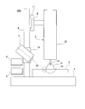
- FIG. 1 First, with reference to FIG. 1, FIG. 2A, and FIG. 2B, the high-temperature part observation apparatus 1 according to the first embodiment of the present disclosure will be described.
- This embodiment is a case where the present invention is applied to high temperature portion observation in downward TIG welding, and the object to be measured is a molten portion.
- 2 indicates a TIG torch
- 3 indicates a workpiece to be welded to the TIG torch
- 4 indicates a pedestal on which the workpiece 3 is placed
- 5 indicates a welding control unit
- Reference numeral 6 denotes a display unit
- the control unit 5 measures temperature based on an image signal from a camera 7 described later.
- the pedestal 4 is provided with a support column 8.
- the support column 8 supports a guide rail 9 extending in the horizontal direction (extending perpendicularly to the paper surface), and the guide rail 9 is movable in the vertical direction.
- a traveling device 11 is provided on the guide rail 9.
- the TIG torch 2 is provided in the traveling device 11 and is movable in a direction perpendicular to the paper surface.
- the TIG torch 2 has a cylindrical shield gas nozzle 12 that ejects a shield gas, and a TIG electrode 13 made of tungsten that is provided concentrically with the shield gas nozzle 12 and protrudes from the tip of the shield gas nozzle 12.
- the TIG electrode 13 is a heat source that emits light by itself, and the length of the TIG electrode 13 is, for example, 20 mm or less.
- the camera 7 is located on the side of the TIG torch 2, and the camera 7 is provided on the support column 8 via the camera guide 16.
- the camera 7 is, for example, a digital camera capable of high-speed shooting, and the camera 7 can continuously shoot the molten pool 15 and the observation region 20 that is the periphery thereof.
- the camera 7 has a CCD or CMOS sensor as an image pickup device, and signals are individually generated from each pixel constituting the image pickup device. Furthermore, the position of the pixel in the image sensor can be specified based on the signal from each pixel.
- the TIG torch 2 can move up and down with respect to the support column 8 and can be fixed at an arbitrary position.
- a light shielding device 17 is provided inside the TIG torch 2.
- 2A and 2B includes a light shielding member 18 that is a light shielding portion, a flange piece 21 that is a holding portion, a compression spring 22 that is a biasing portion that biases the light shielding member 18 downward, and a light shielding device.
- a protective tube 23 for housing the member 18 and the compression spring 22 and a holding release actuator 29 (solenoid) are provided.
- the light shielding member 18 is a cylindrical member formed of a heat resistant member such as ceramic.
- the light shielding member 18 is fitted to the outer peripheral surface of a collet 24 that is a holding member that holds the TIG electrode 13.
- the collet 24 also functions as a guide for the light shielding member 18, and the light shielding member 18 is slidable in the vertical direction along the collet 24.
- the protective tube 23 is fitted on the outer peripheral surface of the light shielding member 18.
- the collet 24, the light shielding member 18, and the protective tube 23 are configured concentrically.
- the light shielding member 18 moves up and down using the collet 24 as a guide and moves up and down in the protective tube 23.
- a flange 25 is formed at the upper end of the light shielding member 18. Further, an inner flange 26 which functions as a stopper is formed at the lower end of the protective tube 23 and functions as a stopper. Further, the upper end of the protective tube 23 is closed and attached to the collet 24. An upper end flange 27 is formed.
- the collet 24 is connected to an external power source (not shown) by an electric wire (not shown). Since the collet 24 is made of, for example, copper, power from an external power source is supplied to the TIG electrode 13 via the collet 24.
- a compression spring 22 as an urging portion is provided between the flange 25 and the upper end flange 27 in a compressed state, and urges the light shielding member 18 downward, that is, in a direction to cover the TIG electrode 13. Further, with the light shielding member 18 raised by a predetermined amount, the collar piece 21 and the flange 25 are engaged, and the light shielding member 18 is held at the raised position.
- the actuator 29 is formed by a solenoid, for example, and releases the engagement between the flange 21 and the flange 25, and releases the holding of the light shielding member 18 by the flange 21.
- the wire 25 penetrating the upper end flange 27 is engaged with the flange 25, and when the wire 28 is pulled up, the light shielding member 18 rises.
- the wire 28 is connected to a pulling device (not shown) or the like, and a pulling force is transmitted to the light shielding member 18 through the wire 28 by driving the pulling device.
- the wire 28 When the flange 25 is engaged with the flange piece 21, the wire 28 is in a freely movable state. Therefore, when the engagement between the flange 25 and the flange piece 21 is released, the light shielding member 18 is restrained by the wire 28. It is possible to move without
- the control unit 5 performs synchronous control of imaging by the camera 7 and driving of the actuator of the rod piece 21, images the observation region 20, measures the temperature, temperature distribution, and temperature change based on the acquired image, and also performs imaging.
- the image and the measurement result are displayed on the display unit 6.
- the control unit 5 applies an electric current to the actuator 29 and operates it, so that the engagement between the flange 21 and the flange 25 is released.
- the light shielding member 18 is instantaneously moved downward by the urging force of the compression spring 22, that is, in a direction to cover the TIG electrode 13.
- the position below the light shielding member 18 is determined.
- the light shielding member 18 moves downward (see FIG. 2B), the light shielding member 18 covers the periphery of the TIG electrode 13 over the entire circumference, and the light emitted from the TIG electrode 13 is blocked by the light shielding member 18.
- reflection of the radiated light at the observation region 20 is prevented, and incidence of the radiated light to the camera 7 is prevented.
- the workpiece 3 is welded by the TIG torch 2.
- An electric current is applied to the TIG electrode 13 protruding from the tip of the shield gas nozzle 12 to generate an arc 14 between the TIG electrode 13 and the workpiece 3.
- the workpiece 14 is melted by the arc 14 and a molten pool 15 is formed.
- the TIG electrode 13 is self-luminous at a high temperature, and the observation region 20 is adjacent to the TIG electrode 13 that is a heat source.
- control unit 5 When acquiring the image of the observation region 20, the control unit 5 operates the actuator 29 simultaneously with or immediately before the extinguishing of the arc 14, for example, 0 second to 0.1 second before, to connect the flange 21 and the flange 25. Release the engagement.
- the light shielding member 18 slides along the collet 24 at a predetermined speed, for example, at a speed of finally 200 mm / sec or more by the biasing force of the compression spring 22.
- the light shielding member 18 covers the entire periphery of the TIG electrode 13 over the entire circumference.
- the control unit 5 operates the shutter of the camera 7 at a predetermined shutter speed, for example, 0.01 seconds immediately after extinguishing the arc 14, for example, 0.03 to 0.06 seconds, and the camera 7 observes the observation region 20. Get the image.
- the influence of the radiation emitted from the TIG electrode 13 can be removed within 0.1 seconds after the arc 14 is extinguished. Further, by operating the camera 7 at the above timing, it is possible to acquire an image in which the influence of the radiated light from the TIG electrode 13 is removed and the influence by covering the periphery of the TIG electrode 13 is minimized. it can.
- the control unit 5 After the image is acquired by the camera 7, the control unit 5 performs predetermined processing such as measurement of the temperature, temperature distribution, and temperature change of the observation region 20 based on the acquired image. In performing predetermined processing such as measurement of the temperature, temperature distribution, and temperature change of the observation region 20, the control unit 5 uses Planck's formula that determines the relationship between luminance and temperature from the luminance of the acquired image. Thus, the temperature can be measured by calculating the temperature. The temperature distribution can be obtained by measuring the temperature over a predetermined spatial range.
- a temperature change ⁇ T (T2 ⁇ T1) at a certain point s is measured by using a measured temperature T1 at a certain point s at a certain time t and a measured temperature T2 at a certain point s at time t + ⁇ t.
- the control unit 5 of the present embodiment calculates the temperature from the brightness of the acquired image using the Planck equation, and further calculates the temperature distribution and the temperature change as described above. Processing such as measurement of the temperature, temperature distribution, and temperature change of the observation region 20 can be performed.
- the image acquired by the camera 7 may be a moving image as well as a still image. Also from the acquired moving image, the control unit 5 can measure the temperature, temperature distribution, and temperature change of the observation region 20 based on the above principle.
- the timing at which the arc 14 is extinguished, the timing at which the actuator 29 is actuated, the timing at which the shutter of the camera 7 is actuated, and the like are based on various conditions such as the biasing force of the compression spring 22 and the TIG electrode 13 is shielded by the light shielding member 18. It is set appropriately so that an image of the observation region 20 immediately after being covered can be acquired. Note that after the image is acquired by the camera 7, the wire 28 is pulled upward, and accordingly, the flange 25 and the light shielding member 18 are pulled upward, and the flange 25 and the flange piece 21 are engaged and lifted. Returning to the state shown in FIG. 2A where the flange 25 is held in position. Returning to the state of FIG. 2A, TIG welding can be resumed.
- the light shielding device 17 is operated immediately before or after the arc 14 is extinguished so that the TIG electrode 13 that emits light at a high temperature immediately after welding is shielded from the light shielding member 18. Then, immediately after the light shielding member 18 covers the TIG electrode 13, an image of the observation region 20 including the molten pool 15 and its peripheral portion is acquired by the camera 7.
- the light shielding member 18 removes the influence of the radiated light from the TIG electrode 13, and the time for covering the TIG electrode 13 becomes very short. Therefore, the light shielding member 18 covering the TIG electrode 13 is heated and shielded from light. It is possible to obtain an image in which the secondary reflection of the radiation light from the member 18 and the change in the temperature state are minimized, and the temperature distribution in the observation region 20 immediately after welding can be accurately measured.
- the light shielding member 18 has a cylindrical shape, slides along the collet 24, and covers the entire periphery of the TIG electrode 13 in the immediate vicinity of the TIG electrode 13, the light emitted from the TIG electrode 13 Does not leak from the light shielding member 18, and the influence of the radiated light from the TIG electrode 13 can be removed with high accuracy.
- the light shielding member 18 covers the TIG electrode 13 over the entire circumference, when the light shielding device 17 is installed, the dimensional accuracy of the light shielding member 18 for preventing leakage of radiated light from the TIG electrode 13 is excessively increased. It is not required and can be installed easily.
- the light shielding device 17 is provided inside the TIG torch 2, and the light shielding member 18 covers the periphery of the TIG electrode 13, that is, the light shielding member 18 is provided between the shield gas nozzle 12 and the TIG electrode 13. Space for providing the light shielding device 17 around the TIG torch 2 is not required, and space saving can be achieved.
- the temperature change state of the observation region 20 can be measured.
- the correlation between the occurrence of hot cracking after welding and the temperature distribution can be obtained.
- FIG. 3 the high-temperature part observation apparatus 100 according to the second embodiment of the present disclosure will be described.
- the same components as those in FIG. 1 are denoted by the same reference numerals, and the description thereof is omitted.
- the light shielding device 31 in the high temperature observation apparatus 100 includes a light shielding member 32, a flange 33 as a holding portion, a flange 34, a compression spring 35 as a biasing portion, and a holding release member. And an actuator 290.
- the light shielding member 32 which is a light shielding portion in the second embodiment is a cylindrical member formed of a heat-resistant member such as ceramic, and is fitted to the outer peripheral surface of the shield gas nozzle 12 so that the shield gas nozzle 12 It can slide up and down along the outer peripheral surface.
- a flange 34 is formed above the light shielding member 32 of the shield gas nozzle 12, and a compression spring 35 is provided between the flange 34 and the light shielding member 32.
- a hole 36 is formed in the middle of the light shielding member 32, and the flange 33 is engaged with the hole 36.
- the light shielding member 32 is held in the raised position, that is, in a state where the TIG electrode 13 is exposed.
- the engagement between the flange piece 33 and the hole 36, that is, the holding of the light shielding member 32 by the flange piece 33 is released, the light shielding member 32 held at the raised position is moved downward, ie, TIG by the urging force of the compression spring 35.
- the electrode 13 is instantaneously moved in a direction to cover the electrode 13, and the periphery of the TIG electrode 13 is covered over the entire circumference.
- the control unit 5 operates the actuator 29 to release the engagement between the flange piece 33 and the hole 36 and momentarily move the light shielding member 32 downward, whereby the TIG electrode 13 is moved by the light shielding member 32. Is obscured over the entire circumference, and radiated light emitted from the TIG electrode 13 toward the observation region 20 can be instantaneously blocked.
- the camera 7 acquires an image of the observation region 20 by the control unit 5, so that the image of the observation region 20 from which the influence of the emitted light from the TIG electrode 13 is removed. And various measurements can be performed based on this image.
- the light shielding member 32 is cylindrical and covers the entire periphery of the TIG electrode 13, the emitted light from the TIG electrode 13 is surrounded by the light shielding member 32. It is possible to remove the influence of the radiated light with high accuracy without leaking out. In addition, when installing the light shielding device 31, the light shielding device 31 can be easily installed without excessively requiring the dimensional accuracy of the light shielding member 32 for preventing leakage of radiated light from the TIG electrode 13. Can do.
- the light shielding member 32 covers the periphery of the shield gas nozzle 12, the light shielding member 32 moves downward and the light shielding member 32 is shielded by the shield gas nozzle 12 when the TIG electrode 13 is shielded by the light shielding member 32. This serves as a guide for the shield gas to be ejected more, and the shield gas can surely reach the molten pool 15.
- the light shielding member 32 is positioned outside the shield gas nozzle 12, and the shield gas flowing through the shield gas nozzle 12 serves as a coolant. For this reason, since the light shielding member 32 is less susceptible to thermal influence from the TIG electrode 13, the light shielding member 32 may be formed of a metal material such as an aluminum material or an iron material.
- the light shielding member 32 When the light shielding member 32 is made of a metal material, the radiated light may be irregularly reflected between the light shielding member 32 and the molten pool 15. Therefore, the light shielding member 32 may be subjected to black treatment such as black alumite treatment if the light shielding member 32 is an aluminum material, and tuftride (registered trademark) treatment if the light shielding member 32 is an iron material.
- black treatment such as black alumite treatment if the light shielding member 32 is an aluminum material
- tuftride (registered trademark) treatment if the light shielding member 32 is an iron material.
- the rod 33 is engaged with the hole 36 to hold the light shielding member 32 in the raised position, that is, the TIG electrode 13 is exposed.
- the welding can be resumed. Since the light shielding member 32 is exposed to the outside, the operator may manually lift the light shielding member 32 upward, or the light shielding member 32 using a member such as the wire 28 of the first embodiment. May be raised upward.
- FIGS. 4, 5A, 5B, 5C, and 5D the same symbols are attached to the same components as those in FIG. 1, FIG. 2A, FIG.
- FIG. 4 is a schematic configuration diagram of a high-temperature part observation apparatus 200 according to the third embodiment of the present disclosure.
- the difference between the configuration of the high-temperature part observation apparatus 200 shown in FIG. 4 and the configuration of the high-temperature part observation apparatus 1 shown in FIG. 1 is that the light shielding member 18 shown in FIG. 1 is not provided in FIG. .
- the light-shielding member 18 that is the light-shielding unit moves downward, so that the light-shielding member 18 is surrounded by the TIG electrode 13 over the entire circumference.
- the light emitted from the TIG electrode 13 is blocked by the light shielding member 18, the reflection of the emitted light at the observation region 20 is prevented, and the incident of the emitted light to the camera 7 is prevented.
- the TIG electrode 130 moves upward, so that the TIG electrode 130 is a light shielding part over the entire circumference. Concealed. Therefore, the radiated light from the TIG electrode 130 is blocked by the shield gas nozzle 12, and reflection of the radiated light at the observation region 20 is prevented, and incidence of the radiated light to the camera 7 is prevented.
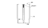
- the light shielding device 201 illustrated in FIG. 5A includes an electric linear actuator 210 that is an urging unit joined to the base end of the TIG electrode 130.
- the electric linear actuator 210 is, for example, the electric linear actuator 210 that slides itself instantaneously upward from the state shown in FIG. 5A. As the electric linear actuator 210 moves, the TIG electrode 130 bonded to the tip of the electric linear actuator 210 is also instantaneously pulled upward. Next, as shown in FIG. 5B, the electric linear actuator 210 holds the TIG electrode 130 in a state where the TIG electrode 130 is covered with the shield gas nozzle 12 over the entire circumference. Here, the TIG electrode 130 is held by the collet 24, and power from an external power source is supplied to the TIG electrode 130 via the collet 24.
- the TIG electrode 130 urged by the electric linear actuator 210 that is the urging unit can slide up and down inside the collet 24. Therefore, the collet 24 holds the TIG electrode to such an extent that the TIG electrode can slide with respect to the inner peripheral surface of the collet 24 and power can be supplied to the TIG electrode 130 via the collet 24.
- the electric linear actuator 210 that is the urging unit is also a holding unit because it can hold the TIG electrode 130 with the TIG electrode 130 shown in FIG. 5A exposed.
- the control unit 5 operates the electric linear actuator 210, pulls the TIG electrode 130 upward, and the shield gas nozzle 12 covers the TIG electrode 130 over the entire circumference.
- the radiated light radiated toward the can be instantaneously blocked.
- the camera 7 acquires an image of the observation region 20 by the control unit 5, so that the image of the observation region 20 from which the influence of the emitted light from the TIG electrode 130 is removed. And various measurements can be performed based on this image. Further, from the state shown in FIG. 5B in which the TIG electrode 130 is obscured over the entire circumference by the shield gas nozzle 12, the TIG electrode 130 is lowered by operating the electric linear actuator 210 which is an urging portion, and FIG. Welding can be resumed by moving to the indicated position.
- the shield gas nozzle 12 since the shield gas nozzle 12 has a structure that covers the periphery of the TIG electrode 130 over the entire circumference, the light shielding members 18 and 32 used in the first embodiment and the second embodiment.
- the radiated light from the TIG electrode 130 does not leak from the periphery of the shield gas nozzle 12, and the influence of the radiated light can be removed with high accuracy.
- the light shielding device 201 when the light shielding device 201 is installed, the light shielding device 201 can be easily installed without excessively requiring the dimensional accuracy of the shield gas nozzle 12 for preventing leakage of radiated light from the TIG electrode 130. it can.
- the shield gas nozzle 12 When the shield gas nozzle 12 is made of a metal material, the radiated light may be irregularly reflected between the shield gas nozzle 12 and the molten pool 15. Therefore, the shield gas nozzle 12 may be subjected to black treatment such as black alumite treatment if the shield gas nozzle 12 is an aluminum material, and tuftride (registered trademark) treatment if the shield gas nozzle 12 is an iron material.
- black treatment such as black alumite treatment if the shield gas nozzle 12 is an aluminum material
- tuftride (registered trademark) treatment if the shield gas nozzle 12 is an iron material.
- the vacuum linear actuator 211 or the tension spring 212 is used as the biasing portion. It may be used.
- the vacuum linear actuator 211 is used as the urging unit, it can be used in the same manner as when the electric linear actuator 210 is used as the urging unit, so that it is the same as the case described above with reference to FIGS. Explanation is applicable.
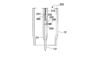
- an example of the light shielding device 202 when the tension spring 212 is used as the urging portion will be described with reference to FIGS. 5C and 5D.
- the light shielding device 202 illustrated in FIG. 5C includes a TIG electrode 131 and a tension spring 212 that is an urging portion joined to the proximal end of the TIG electrode 131.
- the function of the tension spring 212 is to raise the TIG electrode 131 upward, like the electric linear actuator 210 and the vacuum linear actuator 211.
- the urging portion is the tension spring 212
- the TIG electrode 131 is positioned by restricting the vertical movement of the urging portion. That is, near the upper end of the TIG electrode 131, there is provided a reduced diameter concave portion 250 that is reduced so that the outer diameter of the TIG electrode 131 is concave over the entire circumference of the TIG electrode 131. Further, when the TIG electrode 131 shown in FIG.
- the collar piece 230 that is a holding portion that holds the TIG electrode 131 by engaging with the reduced-diameter recess 250 is provided on the collet 24. Is engaged with the reduced-diameter recess 250 of the TIG electrode 131. Therefore, in the state shown in FIG. 5C, the flange 230 holds the tension spring 212 in a state where the tension spring 212 is pulled against the force of the tension spring 212 trying to pull up the TIG electrode 131, and the TIG electrode 131 is lowered. The TIG electrode 131 can be held at a possible position.
- the engagement between the collar piece 230 and the reduced diameter recess 250 is released.
- the TIG electrode 131 is instantaneously pulled upward, and as shown in FIG. 5D, the periphery of the TIG electrode 131 extends around the entire periphery. Is shielded by the shield gas nozzle 12.
- the inner diameter of the collet 24 is reduced above the reduced diameter portion 24n of the collet 24 above the upper end of the TIG electrode 131 so that the TIG electrode 131 cannot enter. .
- the pulling spring 212 applies a pulling force to the TIG electrode 131, so that the TIG electrode 131 is held in the raised position.
- the TIG electrode 131 When the arc 14 is extinguished and welding is completed, the TIG electrode 131 emits light at a high temperature, and the observation region 20 is adjacent to the TIG electrode 131 that is a heat source.
- the control unit 5 operates the actuator 290 to release the engagement between the collar piece 230 and the reduced diameter concave portion 250, operates the tension spring 212, and pulls the TIG electrode 131 upward. Then, the TIG electrode 131 is obscured over the entire circumference by the shield gas nozzle 12, so that the emitted light emitted from the TIG electrode 131 toward the observation region 20 can be instantaneously blocked.
- the camera 7 acquires an image of the observation region 20 by the control unit 5, so that the image of the observation region 20 from which the influence of the emitted light from the TIG electrode 131 is removed. And various measurements can be performed based on this image.
- a wire 280 that can move the TIG electrode 131 up and down is joined to the upper end of the TIG electrode 131.
- the wire 230 is pushed downward from the state shown in FIG. 5D where the TIG electrode 131 is covered by the shield gas nozzle 12 until the collar piece 230 is engaged with the reduced diameter recess 250.
- the TIG electrode 131 is pushed down.
- the TIG electrode 131 is released when the engagement between the collar piece 230 and the reduced diameter concave portion 250 is released. Can move without being constrained by the wire 280.
- the temperature distribution measurement in the case of performing the downward TIG welding is described as an example, but even in the case of performing the upward welding and the lateral welding.
- the high-temperature part observation apparatuses 1, 100, and 200 are applicable.
- the case where the light shielding part is the cylindrical light shielding members 18 and 32 or the cylindrical shield gas nozzle 12 is described.
- the light shielding members 18 and 32 and the shield gas nozzle 12 must always be cylindrical.
- an elliptical cylinder shape, a truncated cone shape, an elliptical truncated cone shape, or the like may be used.
- biasing part is light shielding member 18 and 32, TIG electrode (heat source) If it is a member provided with the function which urges
- a biasing member that biases using a fluid such as air pressure or hydraulic pressure, or a biasing member that biases using a magnetic force may be used.
- radiation light from a heat source can be removed with high accuracy, temperature distribution in an observation region can be accurately measured, and excessive accuracy is not required for the installation of the light shielding device, making the light shielding device easy. It is possible to provide a high-temperature part observation apparatus that exhibits an excellent effect that it can be installed in
Landscapes
- Engineering & Computer Science (AREA)
- Physics & Mathematics (AREA)
- Plasma & Fusion (AREA)
- Mechanical Engineering (AREA)
- General Physics & Mathematics (AREA)
- Spectroscopy & Molecular Physics (AREA)
- Signal Processing (AREA)
- Multimedia (AREA)
- Optics & Photonics (AREA)
- Health & Medical Sciences (AREA)
- Toxicology (AREA)
- Geometry (AREA)
- Radiation Pyrometers (AREA)
- Arc Welding In General (AREA)
Abstract
Description
本開示は、2015年8月18日に日本国に出願された特願2015-160946号に基づき優先権を主張し、その内容をここに援用する。
特許文献2~4にも温度を測定する装置が開示されている。
なお、観察領域20の温度、温度分布、及び温度変化の測定等所定の処理を行うに当たり、制御部5は、取得された画像の輝度から、輝度と温度との関係を定めるプランクの式を用いて温度を計算することで、温度を測定することができる。温度分布は、温度を所定の空間的範囲にわたって測定することで得ることができる。温度変化は、ある地点sのある時刻tにおける測定温度T1と、ある地点sの時刻t+Δtにおける測定温度T2とを用いることで、ある地点sの温度変化ΔT=(T2―T1)を測定することができる。
本実施形態の制御部5は、上記のように、取得された画像の輝度から、温度をプランクの式を用いて算出し、さらに、温度分布や温度変化を上記のように算出することで、観察領域20の温度、温度分布、及び温度変化の測定といった処理を行うことができる。
なお、カメラ7により取得される画像は静止画のみならず、動画であっても良い。取得した動画からも、制御部5は上記の原理で、観察領域20の温度、温度分布、及び温度変化を測定することができる。
なお、カメラ7により画像が取得された後、ワイヤ28が上方に引き上げられ、これに伴い、フランジ25、及び、遮光部材18が上方に引き上げられ、フランジ25と鉤片21が係合し、上昇位置でフランジ25が保持される図2Aに示す状態に戻る。図2Aの状態に戻ると、TIG溶接を再開できる。
なお、図3に点線で示す下降した遮光部材32を上方に引き上げ、鉤片33が孔36に係合して遮光部材32を上昇位置で保持した状態、即ちTIG電極13が露出した状態に戻せば、溶接を再開することができる。なお、遮光部材32は外部に露出しているため、作業者が手作業で遮光部材32を上方に引き上げても良いし、第1の実施形態のワイヤ28のような部材を用いて遮光部材32を上方に引き上げても良い。
一方、本開示の第3の実施形態に係る高温部観察装置200における遮光装置201では、TIG電極130が上方に移動することによって、TIG電極130が全周に亘って遮光部であるシールドガスノズル12に覆隠される。そのため、TIG電極130からの放射光がシールドガスノズル12に遮られ、放射光の観察領域20での反射が防止され、放射光のカメラ7への入射が防止される。
ここで、TIG電極130はコレット24により保持され、かつ、コレット24を介してTIG電極130に外部電源からの電力が供給される。しかしながら、本実施形態の場合、付勢部である電動リニアアクチュエータ210により付勢されたTIG電極130が、コレット24の内部において、上下に摺動可能である。そのため、コレット24は、コレット24の内周面に対してTIG電極が摺動可能で、かつ、コレット24を介してTIG電極130に電力供給可能な程度に、TIG電極を保持している。
ここで、付勢部である電動リニアアクチュエータ210は、図5Aに示すTIG電極130が露出した状態でTIG電極130を保持可能であるため、保持部でもある。
また、シールドガスノズル12によりTIG電極130が全周に亘って覆隠された図5Bに示す状態から、付勢部である電動リニアアクチュエータ210を作動させることでTIG電極130を下降させ、図5Aに示す位置に移動させることにより、溶接を再開することができる。
なお、第3の実施形態において、付勢部として電動リニアアクチュエータ210を使用する場合を一例として記載したが、電動リニアアクチュエータ210に代わって、真空リニアアクチュエータ211や、引張スプリング212を付勢部として用いても良い。付勢部として真空リニアアクチュエータ211を使用する場合は、付勢部として電動リニアアクチュエータ210を使用する場合と同様に使用することができるので、図5A、図5Bを参照した上記の場合と同様の説明が適用可能である。
一方、付勢部として引張スプリング212を使用する場合の遮光装置202の例を図5C、図5Dを参照しながら説明する。
ここで、付勢部が引張スプリング212である場合、付勢部の上下動を制限してTIG電極131の位置決めを行う以下のような構成を有する。
即ち、TIG電極131の上端付近に、TIG電極131の外径がTIG電極131の全周に亘って凹となるように縮小された縮径凹部250が設けられている。また、図5Cに示す、TIG電極131が下降し溶接可能な位置に保持されている場合、縮径凹部250に係合してTIG電極131を保持する保持部である鉤片230が、コレット24を貫通する孔209を貫通して、TIG電極131の縮径凹部250に係合している。そのため、図5Cに示す状態では、鉤片230は、引張スプリング212がTIG電極131を引き上げようとする力に抗して引張スプリング212を引張られた状態で保持し、TIG電極131が下降した溶接可能な位置にTIG電極131を保持することができる。
この際、図5Cに示す状態で、TIG電極131の上端よりも所定距離上方のコレット24の縮径部24nより上方は、TIG電極131が進入できないようにコレット24の内径が縮径されている。従って、引張スプリング212により、TIG電極131が上方に引き上げられても、TIG電極131は縮径部24nにより上昇位置が定められる。なお、TIG電極131が上昇位置にある場合でも、引張スプリング212により、TIG電極131には、上方に引き上げられる力が作用しているため、TIG電極131は上昇位置で保持される。
なお、鉤片230が縮径凹部250と係合した状態では、ワイヤ280は移動可能な自由状態であるため、鉤片230と縮径凹部250との係合が解除されると、TIG電極131はワイヤ280に拘束されることなく移動可能である。
なお、本開示では、遮光部として、円筒状の遮光部材18、32や、円筒状のシールドガスノズル12である場合を記載したが、遮光部材18、32やシールドガスノズル12は常に円筒状である必要は無く、熱源を覆隠すことができれば、楕円筒状や、円錐台状、楕円錐台状等であっても良い。
また、付勢部として、圧縮スプリング22、35、引張スプリング212、電動リニアアクチュエータ210、真空リニアアクチュエータ211である場合を例として記載したが、付勢部は遮光部材18,32やTIG電極(熱源)13、130、131を直線的に付勢する機能を備える部材であれば特に限定されない。例えば、上記のような部材の他にも、空圧や油圧等の流体を用いて付勢する付勢部材や、磁力を用いて付勢する付勢部材であっても良い。
以上、図面を参照しながら本開示の好適な実施形態について説明したが、本開示は上記実施形態に限定されない。上述した実施形態において示した各構成部材の諸形状や組み合わせ等は一例であって、請求項により定められる本開示の範囲において設計要求等に基づき種々変更可能である。
2 TIGトーチ
3 被溶接物
5 制御部
7 カメラ
12 シールドガスノズル
13、130、131 TIG電極(熱源)
15 溶融池
17、31、201、202 遮光装置
18、32 遮光部材
20 観察領域
21、33、230 鉤片
22 圧縮スプリング
23 保護管
25、34 フランジ
212 引張スプリング
Claims (12)
- 熱源に隣接する観察領域の画像を取得可能なカメラと、遮光装置とを有する高温部観察装置であって、前記遮光装置は前記熱源の周囲を覆隠す遮光部と、前記熱源を前記遮光部から露出させる位置で保持する保持部と、前記保持部の保持を解除するアクチュエータとを備え、前記遮光装置を作動させ、前記遮光部により前記熱源が覆隠された直後に前記カメラが前記観察領域の画像を取得する高温部観察装置。
- 前記熱源を覆隠す方向に前記遮光部を付勢する付勢部をさらに備える請求項1に記載の高温部観察装置。
- 前記熱源はTIGトーチの電極であり、前記遮光部は前記電極を収容可能な円筒状の遮光部材である請求項2に記載の高温部観察装置。
- 前記付勢部が圧縮スプリングである請求項3に記載の高温部観察装置。
- 前記熱源はTIGトーチの電極であり、前記遮光部は前記電極の周囲に設けられたシールドガスノズルの外周面に嵌合され、前記シールドガスノズルに沿って移動する円筒状の遮光部材である請求項2に記載の高温部観察装置。
- 前記付勢部が圧縮スプリングである請求項5に記載の高温部観察装置。
- 前記遮光部により覆隠される方向に前記熱源を付勢する付勢部をさらに備える請求項1に記載の高温部観察装置。
- 前記熱源はTIGトーチの電極であり、前記遮光部が前記電極の周囲に設けられた円筒状のシールドガスノズルである請求項7に記載の高温部観察装置。
- 前記付勢部が電動リニアアクチュエータである請求項8に記載の高温部観察装置。
- 前記付勢部が真空リニアアクチュエータである請求項8に記載の高温部観察装置。
- 前記付勢部が引張スプリングである請求項8に記載の高温部観察装置。
- 前記カメラは高速度撮影が可能なデジタルカメラであり、前記観察領域の画像を連続して取得可能な請求項1~請求項11のいずれか1項に記載の高温部観察装置。
Priority Applications (5)
| Application Number | Priority Date | Filing Date | Title |
|---|---|---|---|
| KR1020187004864A KR101962584B1 (ko) | 2015-08-18 | 2016-08-17 | 고온부 관찰 장치 |
| JP2017535548A JP6369636B2 (ja) | 2015-08-18 | 2016-08-17 | 高温部観察装置 |
| CN201680048541.9A CN107923797B (zh) | 2015-08-18 | 2016-08-17 | 高温部观察装置 |
| EP16837131.8A EP3339824A4 (en) | 2015-08-18 | 2016-08-17 | DEVICE FOR OBSERVING A HIGH-TEMPERATURE PART |
| US15/896,885 US10412323B2 (en) | 2015-08-18 | 2018-02-14 | High-temperature object observation device |
Applications Claiming Priority (2)
| Application Number | Priority Date | Filing Date | Title |
|---|---|---|---|
| JP2015-160946 | 2015-08-18 | ||
| JP2015160946 | 2015-08-18 |
Related Child Applications (1)
| Application Number | Title | Priority Date | Filing Date |
|---|---|---|---|
| US15/896,885 Continuation US10412323B2 (en) | 2015-08-18 | 2018-02-14 | High-temperature object observation device |
Publications (1)
| Publication Number | Publication Date |
|---|---|
| WO2017030142A1 true WO2017030142A1 (ja) | 2017-02-23 |
Family
ID=58052220
Family Applications (1)
| Application Number | Title | Priority Date | Filing Date |
|---|---|---|---|
| PCT/JP2016/073983 Ceased WO2017030142A1 (ja) | 2015-08-18 | 2016-08-17 | 高温部観察装置 |
Country Status (6)
| Country | Link |
|---|---|
| US (1) | US10412323B2 (ja) |
| EP (1) | EP3339824A4 (ja) |
| JP (1) | JP6369636B2 (ja) |
| KR (1) | KR101962584B1 (ja) |
| CN (1) | CN107923797B (ja) |
| WO (1) | WO2017030142A1 (ja) |
Cited By (1)
| Publication number | Priority date | Publication date | Assignee | Title |
|---|---|---|---|---|
| CN107923797A (zh) * | 2015-08-18 | 2018-04-17 | 株式会社 Ihi | 高温部观察装置 |
Families Citing this family (2)
| Publication number | Priority date | Publication date | Assignee | Title |
|---|---|---|---|---|
| CN111163251B (zh) * | 2020-01-06 | 2021-03-19 | 北京卫星环境工程研究所 | 用于真空、高低温环境下的视角可变的摄像系统 |
| WO2025079803A1 (ko) * | 2023-10-11 | 2025-04-17 | 한국기초과학지원연구원 | 광학 프로브를 이용한 온도 분포 측정 장치 |
Citations (6)
| Publication number | Priority date | Publication date | Assignee | Title |
|---|---|---|---|---|
| US4644131A (en) * | 1986-04-22 | 1987-02-17 | The Ohio State University Research Foundation | Electrode support for gas arc welding torch having coaxial vision |
| JPH0464464U (ja) * | 1990-10-16 | 1992-06-02 | ||
| JPH0716744A (ja) * | 1993-06-17 | 1995-01-20 | Nippon Steel Corp | アーク溶接の撮影方法およびその装置 |
| JP2007192579A (ja) * | 2006-01-17 | 2007-08-02 | Toyota Motor Corp | 温度計測装置及び温度計測方法 |
| JP2013545620A (ja) * | 2010-12-14 | 2013-12-26 | リンカーン グローバル,インコーポレイテッド | 手動溶接装置に自動ワイヤ引込方法を提供する手動溶接方法 |
| JP2015179010A (ja) * | 2014-03-19 | 2015-10-08 | 株式会社Ihi | 高温部観察装置 |
Family Cites Families (26)
| Publication number | Priority date | Publication date | Assignee | Title |
|---|---|---|---|---|
| US4365307A (en) * | 1981-02-25 | 1982-12-21 | Sumitomo Kinzoku Kogyo Kabushiki Gaisha | Temperature pattern measuring device |
| JPS6033874A (ja) * | 1983-08-03 | 1985-02-21 | Mitsubishi Heavy Ind Ltd | ア−ク溶接用ロボット |
| JPS61286064A (ja) * | 1985-06-11 | 1986-12-16 | Ishikawajima Harima Heavy Ind Co Ltd | テレビカメラによる溶接部の監視方法 |
| US4724301A (en) * | 1985-10-21 | 1988-02-09 | Hitachi, Ltd. | Apparatus utilizing light stripe image for detecting portion to be welded prior to welding thereof |
| US5275327A (en) * | 1992-10-13 | 1994-01-04 | Eg&G Idaho, Inc. | Integrated optical sensor |
| JPH08240833A (ja) | 1995-03-02 | 1996-09-17 | Mitsubishi Electric Corp | 車両用カメラの露光制御装置 |
| JPH09141432A (ja) * | 1995-11-20 | 1997-06-03 | Hitachi Zosen Corp | 溶接監視装置 |
| JP2000131149A (ja) | 1998-10-23 | 2000-05-12 | Mitsubishi Electric Corp | 赤外線温度計測装置 |
| JP2004061481A (ja) | 2002-07-31 | 2004-02-26 | Risho:Kk | 溶融金属内部温度測定用放射温度計 |
| FR2876607B1 (fr) * | 2004-10-19 | 2007-12-14 | Snecma Moteurs Sa | Outil de soudage |
| JP2008260055A (ja) * | 2007-04-16 | 2008-10-30 | Fujikura Ltd | 溶接観察装置 |
| JP2008268106A (ja) | 2007-04-24 | 2008-11-06 | Mitsui Optronics:Kk | 温度情報計測方法 |
| JP2008275482A (ja) | 2007-04-27 | 2008-11-13 | Kobe Steel Ltd | パス間温度測定装置及びパス間温度測定装置を使用した溶接方法 |
| JP5088048B2 (ja) * | 2007-08-24 | 2012-12-05 | 株式会社安川電機 | Tigアーク溶接装置 |
| US20090161212A1 (en) * | 2007-12-21 | 2009-06-25 | Gough Yuma E | Weld viewing |
| CN201378240Y (zh) * | 2008-12-25 | 2010-01-06 | 北京石油化工学院 | 自动变光遮光水下焊接摄像机 |
| CN101710226B (zh) * | 2009-11-26 | 2011-05-04 | 天津市电视技术研究所 | 风冷式摄像机 |
| CN101870030A (zh) * | 2010-06-29 | 2010-10-27 | 哈尔滨工业大学 | 外加辅助光源的铝合金tig焊反面熔池视觉图像检测装置与方法 |
| CN102353620B (zh) * | 2011-06-21 | 2013-09-25 | 吉林大学 | 测定高温润湿性装置及方法 |
| JP6092616B2 (ja) * | 2012-12-27 | 2017-03-08 | 川崎重工業株式会社 | 狭開先用溶接装置 |
| US10543551B2 (en) * | 2013-09-16 | 2020-01-28 | Illinois Tool Works Inc. | Synchronized rotating arc welding method and system |
| CN103773920B (zh) * | 2014-01-25 | 2015-12-30 | 湖南镭目科技有限公司 | 转炉钢水温度检测系统 |
| CN203807498U (zh) * | 2014-04-21 | 2014-09-03 | 唐山方大天正电子有限公司 | 高炉炉内成像监控装置 |
| CN204177231U (zh) * | 2014-09-30 | 2015-02-25 | 北京首钢自动化信息技术有限公司 | 一种360°旋转可调的高温炉内成像装置 |
| CN104227185B (zh) * | 2014-10-13 | 2016-03-16 | 哈尔滨工业大学(威海) | 一种水下湿法焊接观测仪及使用方法 |
| EP3339824A4 (en) * | 2015-08-18 | 2019-07-03 | IHI Corporation | DEVICE FOR OBSERVING A HIGH-TEMPERATURE PART |
-
2016
- 2016-08-17 EP EP16837131.8A patent/EP3339824A4/en not_active Withdrawn
- 2016-08-17 CN CN201680048541.9A patent/CN107923797B/zh active Active
- 2016-08-17 KR KR1020187004864A patent/KR101962584B1/ko not_active Expired - Fee Related
- 2016-08-17 WO PCT/JP2016/073983 patent/WO2017030142A1/ja not_active Ceased
- 2016-08-17 JP JP2017535548A patent/JP6369636B2/ja active Active
-
2018
- 2018-02-14 US US15/896,885 patent/US10412323B2/en active Active
Patent Citations (6)
| Publication number | Priority date | Publication date | Assignee | Title |
|---|---|---|---|---|
| US4644131A (en) * | 1986-04-22 | 1987-02-17 | The Ohio State University Research Foundation | Electrode support for gas arc welding torch having coaxial vision |
| JPH0464464U (ja) * | 1990-10-16 | 1992-06-02 | ||
| JPH0716744A (ja) * | 1993-06-17 | 1995-01-20 | Nippon Steel Corp | アーク溶接の撮影方法およびその装置 |
| JP2007192579A (ja) * | 2006-01-17 | 2007-08-02 | Toyota Motor Corp | 温度計測装置及び温度計測方法 |
| JP2013545620A (ja) * | 2010-12-14 | 2013-12-26 | リンカーン グローバル,インコーポレイテッド | 手動溶接装置に自動ワイヤ引込方法を提供する手動溶接方法 |
| JP2015179010A (ja) * | 2014-03-19 | 2015-10-08 | 株式会社Ihi | 高温部観察装置 |
Non-Patent Citations (1)
| Title |
|---|
| See also references of EP3339824A4 * |
Cited By (2)
| Publication number | Priority date | Publication date | Assignee | Title |
|---|---|---|---|---|
| CN107923797A (zh) * | 2015-08-18 | 2018-04-17 | 株式会社 Ihi | 高温部观察装置 |
| US10412323B2 (en) | 2015-08-18 | 2019-09-10 | Ihi Corporation | High-temperature object observation device |
Also Published As
| Publication number | Publication date |
|---|---|
| US20180176485A1 (en) | 2018-06-21 |
| EP3339824A1 (en) | 2018-06-27 |
| JP6369636B2 (ja) | 2018-08-08 |
| EP3339824A4 (en) | 2019-07-03 |
| CN107923797B (zh) | 2020-04-28 |
| KR20180030682A (ko) | 2018-03-23 |
| KR101962584B1 (ko) | 2019-03-26 |
| JPWO2017030142A1 (ja) | 2018-02-01 |
| CN107923797A (zh) | 2018-04-17 |
| US10412323B2 (en) | 2019-09-10 |
Similar Documents
| Publication | Publication Date | Title |
|---|---|---|
| JP6369636B2 (ja) | 高温部観察装置 | |
| US20150153292A1 (en) | Thermal Analyzer | |
| EP2876466B1 (en) | Radiation image acquisition device | |
| JP2011229620A5 (ja) | ||
| TWI620931B (zh) | Photographing device for thermal analysis device, and thermal analysis device therewith | |
| JP2001249007A5 (ja) | ||
| JP2015025786A (ja) | 高温割れ評価装置 | |
| CN105628210A (zh) | 高温检测装置、其校准方法及用于生产三维工件的设备 | |
| JP2017080042A5 (ja) | ||
| KR20210089750A (ko) | 유리 워크피스를 용접하는 용접 프로세스를 모니터링하는 방법 및 장치 | |
| WO2015109857A1 (zh) | 转炉钢水温度检测系统 | |
| JP2013122389A (ja) | 気体検出装置 | |
| JP5925725B2 (ja) | 積分球、および、反射光の測定方法 | |
| CN102246022B (zh) | 炉内观察装置 | |
| JP5535347B1 (ja) | 撮像装置、半導体製造装置および半導体製造方法 | |
| JP6269216B2 (ja) | 高温部観察装置 | |
| JP2017075894A (ja) | 鋼板の温度測定方法及び温度測定装置並びに鋼板の製造方法 | |
| JP5455128B2 (ja) | 流路孔検査方法及びその装置 | |
| KR20170027482A (ko) | 관 내면 검사장치 | |
| JP2015099168A (ja) | 気体検出装置 | |
| JP2017040495A (ja) | 高温部観察装置 | |
| JP2017513010A5 (ja) | ||
| KR102224619B1 (ko) | 방사선 검사장치의 선원 예측 콜리메타 | |
| JP2016098388A (ja) | 溶射粉末の流路の撮影方法及び溶射フレーム中への溶射粉末投入位置の調整方法 | |
| JP5741720B2 (ja) | X線撮像装置 |
Legal Events
| Date | Code | Title | Description |
|---|---|---|---|
| 121 | Ep: the epo has been informed by wipo that ep was designated in this application |
Ref document number: 16837131 Country of ref document: EP Kind code of ref document: A1 |
|
| ENP | Entry into the national phase |
Ref document number: 2017535548 Country of ref document: JP Kind code of ref document: A |
|
| ENP | Entry into the national phase |
Ref document number: 20187004864 Country of ref document: KR Kind code of ref document: A |
|
| NENP | Non-entry into the national phase |
Ref country code: DE |
|
| WWE | Wipo information: entry into national phase |
Ref document number: 2016837131 Country of ref document: EP |