WO2017030180A1 - 通信システム、通信機器および通信システムの再接続方法 - Google Patents
通信システム、通信機器および通信システムの再接続方法 Download PDFInfo
- Publication number
- WO2017030180A1 WO2017030180A1 PCT/JP2016/074191 JP2016074191W WO2017030180A1 WO 2017030180 A1 WO2017030180 A1 WO 2017030180A1 JP 2016074191 W JP2016074191 W JP 2016074191W WO 2017030180 A1 WO2017030180 A1 WO 2017030180A1
- Authority
- WO
- WIPO (PCT)
- Prior art keywords
- communication
- communication device
- network
- wireless
- connection
- Prior art date
- Legal status (The legal status is an assumption and is not a legal conclusion. Google has not performed a legal analysis and makes no representation as to the accuracy of the status listed.)
- Ceased
Links
Images




Classifications
-
- H—ELECTRICITY
- H04—ELECTRIC COMMUNICATION TECHNIQUE
- H04W—WIRELESS COMMUNICATION NETWORKS
- H04W76/00—Connection management
- H04W76/10—Connection setup
- H04W76/19—Connection re-establishment
-
- H—ELECTRICITY
- H04—ELECTRIC COMMUNICATION TECHNIQUE
- H04W—WIRELESS COMMUNICATION NETWORKS
- H04W40/00—Communication routing or communication path finding
- H04W40/34—Modification of an existing route
-
- H—ELECTRICITY
- H04—ELECTRIC COMMUNICATION TECHNIQUE
- H04W—WIRELESS COMMUNICATION NETWORKS
- H04W76/00—Connection management
- H04W76/30—Connection release
-
- H—ELECTRICITY
- H04—ELECTRIC COMMUNICATION TECHNIQUE
- H04W—WIRELESS COMMUNICATION NETWORKS
- H04W84/00—Network topologies
- H04W84/02—Hierarchically pre-organised networks, e.g. paging networks, cellular networks, WLAN [Wireless Local Area Network] or WLL [Wireless Local Loop]
- H04W84/10—Small scale networks; Flat hierarchical networks
- H04W84/12—WLAN [Wireless Local Area Networks]
-
- H—ELECTRICITY
- H04—ELECTRIC COMMUNICATION TECHNIQUE
- H04W—WIRELESS COMMUNICATION NETWORKS
- H04W84/00—Network topologies
- H04W84/18—Self-organising networks, e.g. ad-hoc networks or sensor networks
-
- H—ELECTRICITY
- H04—ELECTRIC COMMUNICATION TECHNIQUE
- H04W—WIRELESS COMMUNICATION NETWORKS
- H04W84/00—Network topologies
- H04W84/18—Self-organising networks, e.g. ad-hoc networks or sensor networks
- H04W84/20—Leader-follower arrangements
-
- H—ELECTRICITY
- H04—ELECTRIC COMMUNICATION TECHNIQUE
- H04W—WIRELESS COMMUNICATION NETWORKS
- H04W88/00—Devices specially adapted for wireless communication networks, e.g. terminals, base stations or access point devices
- H04W88/02—Terminal devices
- H04W88/04—Terminal devices adapted for relaying to or from another terminal or user
Definitions
- This disclosure relates to an audio system (communication system) in which a plurality of audio devices (communication devices) are connected via a network.
- each audio device has been conventionally connected to each other with an analog or digital audio cable.
- a network particularly a wireless network
- it has been considered to connect devices via a network (particularly a wireless network) and transmit / receive voice signals and command messages in packets.
- the audio cable is required for every input / output, but the connection is completed if it is physically connected to the terminal of the device.
- a wireless network requires setting of an SSID, a password, and the like, and the setting work is more complicated than connection of a cable.
- the access point of the connection destination stops it is necessary to change the connection destination and reconnect, but this work is also troublesome as in the first connection.
- an object of the present disclosure is to enable automatic reconnection even when a communication device is disconnected from the network in a communication system that connects a plurality of communication devices using a network.
- a communication system includes: A plurality of communication devices connected to each other so as to constitute a network are provided, Each of the plurality of communication devices includes a first wireless communication unit that functions as a wireless relay device of the network, and a second wireless communication unit that functions as a slave unit connected to another communication device in the network, When the second wireless communication unit of the lower communication device accesses the first wireless communication unit of the higher communication device, the higher communication device and the lower communication device are connected to form the network, Each of the plurality of communication devices stores system information including connection information to the first wireless communication unit of each communication device constituting the network, When any one of the plurality of communication devices is disconnected from a higher-level communication device being connected, the disconnected communication device is another communication device that configures the network using the system information. And reconnect to the communication device detected by the search, It is a communication system.
- the communication device of the present disclosure is A first wireless communication unit that functions as a wireless relay device of the network; A second wireless communication unit that functions as a slave connected to another communication device in the network; A storage unit for storing system information including connection information to the first wireless communication unit of another communication device constituting the network; A control unit; With When the second wireless communication unit is disconnected from the first wireless communication unit of the connected higher-level communication device, the control unit searches for another communication device configuring the network using the system information. , Reconnect to other communication devices detected by the search, It is a communication device.
- a plurality of communication devices are connected to form a network, and each of the plurality of communication devices functions as a wireless relay device of the network;
- a second wireless communication unit that functions as a slave unit connected to another device in the network, and the second wireless communication unit of the lower communication device accesses the first wireless communication unit of the higher communication device,
- the upper communication device and the lower communication device are connected so as to constitute the network, and each of the plurality of communication devices includes connection information to the first wireless communication unit of each communication device constituting the network.
- a reconnection method for a communication system storing information comprising: When any one of the plurality of communication devices is disconnected from a higher-level communication device being connected, the disconnected communication device is another communication device that configures the network using the system information. And reconnect to the communication device detected by the search, A reconnection method of a communication system.
- FIG. 1 is a configuration diagram of an audio system to which the present disclosure is applied.
- FIG. 2 is a block diagram of a mobile phone that functions as a controller to which this disclosure is applied.
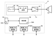
- FIG. 3 is a block diagram of an audio device to which the present disclosure is applied.
- FIG. 4 is a diagram illustrating an example of a system management table set in the host device and the controller.
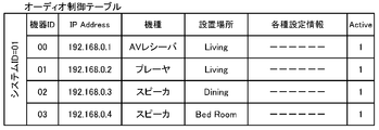
- FIG. 5 is a diagram showing an example of an audio control table set in the controller
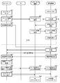
- FIG. 6 is a diagram showing a communication procedure between the controller and the audio device.
- FIG. 7 is a diagram showing a communication procedure between the controller and the audio device.
- FIG. 8 is a diagram showing a communication procedure between the controller and the audio device.
- FIG. 9 is a diagram showing a communication procedure between the controller and the audio device.
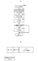
- FIG. 10A and 10B are flowcharts showing the system information transmission operation of the host device.
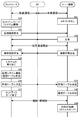
- FIG. 11 is a diagram showing a communication procedure when reconnecting an audio device.
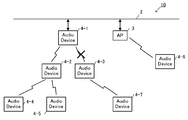
- FIG. 12 is a diagram for explaining a connection destination change mode at the time of reconnection in the audio system.
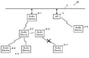
- FIG. 13 is a diagram for explaining a connection destination change mode at the time of reconnection in the audio system.
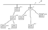
- FIG. 14 is a diagram for explaining a connection destination change mode at the time of reconnection in the audio system.
- FIG. 15 is a diagram for explaining a connection destination change mode at the time of reconnection in the audio system.
- FIG. 1 is a diagram illustrating a configuration of an audio system to which the present disclosure is applied.
- the audio system 10 includes a plurality of audio devices 4 (4-1 to 4-8) connected via a network 9 including a wired LAN 2 and an access point (external access point) 3, and a multi-function mobile phone that functions as the controller 1 1 (hereinafter referred to as a mobile phone).
- the audio devices 4 transmit and receive audio signals to and from each other via the network 9.
- the controller 1 transmits a command message to the audio device 4 via the network 9.
- Each audio device 4 (hereinafter also referred to as a component device) constituting the audio system 10 has a wired LAN function and two wireless LAN functions.
- the audio device 4 can activate the access point using one of the two wireless LAN functions.
- An access point activated by the audio device 4 is called an internal access point 4A.
- the lower audio device 4 is connected to the internal access point 4A.
- the internal access point 4A normally operates in a stealth mode (except for the initial connection described later), so that it is difficult for other devices to know its presence.
- the other wireless LAN function functions as a slave unit of the wireless LAN and is connected to the internal access point 4A or the external access point 3 of the host audio device 4.
- An access point (external access point) 3 is connected to the wired LAN 2.
- the audio device 4-1 is connected to the wired LAN 2 with a cable.
- the audio devices 4-2 and 4-3 are connected to the internal access point 4A-1 of the upper audio device 4-1 by a wireless LAN.
- the audio devices 4-4 and 4-5 are connected to the internal access point 4A-2 of the upper audio device 4-2 via a wireless LAN.
- the audio devices 4-6 and 4-7 are connected to the internal access point 4A-3 of the upper audio device 4-3 by a wireless LAN.
- the audio device 4-8 is connected to the external access point 3.
- the network 9 is composed of a wired LAN 2 and a wireless LAN including an external access point 3 and an internal access point 4A.
- Ethernet registered trademark: IEEE 802.3
- Wi-Fi IEEE 802.11g
- Each audio device 4 is called a root device, a node device, a leaf device, and a branch device according to the connection form to the wired LAN 2.
- the root device is the highest-level device connected directly (with a cable) to the wired LAN 2, and in FIG. 1, the audio device 4-1 is the root device.
- the root device is an audio device that is first registered when the audio system 10 is constructed, and serves as a base point of the audio system 10.
- the root device activates the internal access point 4 ⁇ / b> A for connecting the lower audio device 4 to the network and joining the audio system 10. All the music information reproduced by the audio device 4 (node device, leaf device) connected below the root device is transmitted via this.
- the node device is a middle device connected to the root device (the internal access point 4A of the root device) via a wireless LAN, and the audio devices 4-2 and 4-3 in FIG. 1 are node devices.
- the node device activates the internal access point 4A for connecting the lower audio device 4 to the network and joining the audio system 10. Music information reproduced by the audio device 4 (leaf device) connected to the node device and below is transmitted via this.
- the leaf device is a subordinate device connected to the node device (the internal access point 4A of the node device) by the wireless LAN.
- the audio devices 4-4, 4-5, 4-6, and 4-7 are It is a leaf device.
- the leaf device does not activate the internal access point 4A, but may activate it.
- the branch device is an audio device 4 that is connected to the external access point 3 by a wireless LAN separately from the tree having the root device as a vertex and communicates with other audio devices 4 in the audio system 10 via the wired LAN 2.
- the audio device 4-8 is a branch device.
- the branch device does not activate the internal access point 4A, but may activate it.
- connection of up to two node devices is permitted to the root device in order to transmit high-quality audio signals.
- Each node device is permitted to connect up to two leaf devices.
- the hierarchy of connections using the internal access point 4A is limited to three levels of root device-node device-leaf device. Therefore, up to seven audio devices including the root device can be connected by the wireless LAN tree having the root device as the apex.
- the maximum number (seven) of audio devices 4 (4-1 to 4-7) that can be connected is connected to the tree shown in FIG.
- the number of branch devices is not limited, the number of audio devices 4 in the entire audio system 10 is limited to 10 as the control target of the controller 1.
- the maximum number such as the number of tree hierarchies and the number of lower devices connectable to each audio device 4 is not limited to this embodiment.
- the cellular phone 1 functions as an audio system controller (hereinafter referred to as a controller) 1 when an audio system control program 70 (see FIG. 2) is activated.
- the mobile phone 1 (controller 1) communicates with the audio device 4 belonging to the audio system 10 via the network 9. Through this communication, the controller 1 plays back the audio source (for example, which music device 4 plays which music, which music is delivered to which audio device 4) and the volume of the audio source. Control etc.
- Each audio device 4 communicates with the audio device 4 to which the audio device 4 belongs via the network 9 to transmit and receive audio signals to and from each other.
- the mobile phone 1 is a multi-function phone called a so-called smartphone.
- the mobile phone 1 has a 3G / 4G communication function, which is a mobile communication network, a wireless LAN (Wi-Fi) communication function, and a Bluetooth (registered trademark) communication function.
- the cellular phone 1 functions as the controller 1 by activating an audio system control program 70 that is an application program, communicates with the audio device 4 of the audio system via the network 3, and transmits a command message corresponding to a user operation to the audio. It transmits to the apparatus 4 and controls an audio system.
- the mobile phone 1 is capable of performing control unit 20, operation unit 30, media interface 31, wireless LAN communication circuit 32, 3G / 4G communication circuit 33, and Bluetooth (registered trademark) communication on bus 26.
- a distance wireless communication circuit 34 is provided.
- the control unit 20 includes a CPU 21, a ROM (flash memory) 22, a RAM 23, an image processor 24 and an audio processor 25.
- a video RAM (VRAM) 40 is connected to the image processor 24, and a display unit 41 is connected to the VRAM 40.
- the display unit 41 includes a liquid crystal display. The display shows a standby screen, a telephone number, and the like. When functioning as the controller 1, a screen for controlling the audio device 4 is displayed.
- An amplifier 42 including a D / A converter is connected to the audio processor 25, and the speaker 16 is connected to the amplifier 42.
- the image processor 24 includes a GPU (Graphics Processing Unit) that generates various images such as a standby screen and a telephone number.
- the image processor 24 When the audio system control program 70 is activated, the image processor 24 generates an image of the audio controller in accordance with an instruction from the CPU 21 and develops it on the VRAM 40. The image developed on the VRAM 40 is displayed on the display unit 41.
- GPU Graphics Processing Unit
- the voice processor 25 has a DSP (Digital Signal Processor) that encodes / decodes call voice.
- the audio processor 25 outputs the decoded / generated audio to the amplifier 42.
- the amplifier 42 amplifies this audio signal and outputs it to the speaker 16.
- the wireless LAN communication circuit 32 performs wireless communication with a router in accordance with a standard such as IEEE 802.11g, and communicates with the audio device 4 via the access points 3 and 7.
- the 3G / 4G communication circuit 33 performs a voice call and data communication via a mobile phone communication network.
- the short-range wireless communication circuit 34 communicates with other Bluetooth (registered trademark) compatible devices, and performs transmission and reception of audio signals, for example.
- the operation unit 30 includes a touch panel formed on the display unit 41, and detects a touch operation and a flick operation on the touch panel.
- the display unit 41 displays a plurality of operators such as a setup button and a scan button.
- the operation unit 30 detects a user's touch operation and its coordinates on the touch panel, and determines which operator has been operated.
- the memory card 15 is connected to the media interface 31.
- the memory card 15 is a micro SD card, for example.
- the audio system control program 70 is stored in the memory card 15 or the ROM 22. In this embodiment, it is assumed that the audio system control program 70 is stored in the memory card 15 as shown in FIG.
- the audio system control program 70 may be downloaded by 3G / 4G or wireless LAN data communication, and may be stored in the ROM 22 or the memory card 15 in advance.
- a storage area 71 for storing the configuration of the audio system is set in the memory card 15.
- the ROM 22 stores a basic program for executing calls and application programs of the mobile phone 1.
- the ROM 22 is a flash memory that can store a downloaded application program in addition to a basic program.
- a work area used when the CPU 20 executes the audio system control program 70 is set.
- the audio device 4 includes a control unit 50, an audio processing unit 51, and an operation unit 59, and includes two wireless LAN communication units (RF modules) 56 and 57 and a wired LAN communication unit 58.
- the operation unit 59 has a connect button 59A in addition to a volume operator (not shown).
- the control unit 50 includes a CPU and a memory, and stores an audio system program.
- the control unit 50 controls the operations of the audio processing unit 51, the wireless LAN communication units 56 and 57, and the wired LAN communication unit 58 according to the audio system program. Further, when the connect button 59A is pressed, the control unit 50 performs an initial connection operation that is an operation for connecting the audio device 4 to the network 9. Details of the initial connection operation will be described later.
- the wireless LAN communication unit 56 performs wireless communication with the external access point 3 or the internal access point 4A of the upper audio device 4 according to a wireless LAN standard such as IEEE802.11g.
- the other wireless LAN communication unit 57 is activated as an access point (internal access point 4A) and relays other audio devices (eg, audio devices 4-2 and 4-3) to the wired LAN 2.
- the wireless LAN communication unit 57 is activated as a temporary access point for initial connection even when the audio device 4 is initially connected, and communicates with the controller 1 (mobile phone 1). The operation at the time of initial connection will be described later.
- the two wireless LAN communication units 56 and 57 may be realized by operating one piece of hardware in a time division manner.
- the wired LAN communication unit 58 has a cable connector, and performs communication via the wired LAN 2-access point 3 in accordance with a communication standard such as IEEE802.3.
- a controller (mobile phone) 1 is connected to the access point 3, and the control unit 50 communicates with the controller 1 via the network 9 to transmit an operation state and receive a command message.
- the SSID and password of the internal access point 4A are a character string that can be determined from the MAC address of the wireless LAN communication unit 57.
- the MAC address expressed in octets is used as the SSID
- the lower three octets (model ID + serial number) are used as the password.
- an audio device newly participating in the audio system can discover the internal access point 4A based on the SSID, that is, based on the vendor ID and model ID of the MAC address, and generates its own password. Then, it is possible to connect to the internal access point 4A. Thereby, when connecting to the internal access point 4A, it is possible to omit the input of the SSID and password by the user.
- the method of generating the SSID and password of the internal access point 4A is not limited to the above.
- the audio processing unit 51 includes a tuner 52, an audio circuit 53, and a power amplifier 54.
- the tuner 52 receives an audio signal from FM broadcasting or the Internet and inputs it to the audio circuit 53.
- the audio circuit 53 performs processing such as equalization and volume adjustment on the input audio signal, and then outputs the processed audio signal to the power amplifier 54.
- the power amplifier 54 amplifies the input audio signal and outputs it to an externally connected speaker 55.
- the speaker 55 emits the input audio signal as sound.
- the audio devices 4-1 to 4-8 may be different devices, but the basic configuration of the communication function and the audio signal processing function is shown in FIG.
- FIG. 4 and 5 are diagrams showing an example of a table for managing the audio system.
- FIG. 4 is a system management table for managing the connection form of each audio device 4 in the network 9.
- FIG. 5 is an audio control table for managing the operation of each audio device 4 in the audio system 10.
- the system management table is mainly used for network connection management by the root device 4-1.
- the audio control table is mainly used by the controller 1 for audio source reproduction control.
- the system management table stores the connection form of each audio device 4 (component device) constituting the audio system 10, and is created by the controller 1 when the audio system 10 is constructed. Further, when a new audio device 4 is added to the audio system 10, the controller 1 performs an update for adding the audio device 4.
- the system management table created or added / updated is transmitted from the controller 1 to the root device 4-1. Thereafter, the system management table is updated by the root device 4-1 every time any component device is disconnected or reconnected during the operation of the audio system 10.
- the root device 4-1 periodically transmits all or part of the contents of the system management table to the component devices and the controller 1 as system information. Thereby, each component device and the controller 1 can always hold the latest system information. The detailed operation for transmitting the system information will be described later.
- the system management table is identified by a system ID for identifying the audio system 10.
- Each component device is associated with the device ID of each device, and the upper side (slave unit side) / lower side (internal access point side) MAC address (that is, the MAC address of the wireless LAN communication unit 56/57), upper side / Lower side IP address (that is, IP address of wireless LAN communication unit 56/57), number of connection stages from root device 4-1 (number of HOP), presence / absence of activation of internal access point, connection to internal access point 4A Information such as the number of subordinate devices (the number of children) and operation state (communication enabled / disabled) information (Active) is stored.
- Each component device has an individual IP address, but in this audio system 10, a multicast address is set as a multicast group.
- a multicast address is set as a multicast group.
- the system information packet may be transmitted by unicast to the IP address of each component device, but the load on the network 9 can be reduced by multicast transmission.
- the audio control table in FIG. 5 is associated with the device ID of each device, and the upper IP address (IP address of the wireless LAN communication unit 56), model, installation location, operation state information, and volume value of each component device. Various setting information such as a display name is stored.
- Each column of the audio control table is associated with each column of the system management table by a device ID.
- the controller 1 creates a control screen based on the contents of the audio control table and accepts control of each component device by the user.
- the root device 4-1 is set and the audio system 10 is constructed. Thereafter, the audio device 4 other than the root device 4-1 is added to the audio system 10. The user performs the following procedure.
- the audio device 4-1 as the root device is connected to the wired LAN 2 with a cable.
- the controller 1 is activated in the setup mode on the mobile phone 1.
- the connect button 59A of the audio device 4-1 is pressed. If the user performs the above work, the controller 1 and the route device 4-1 communicate with each other and automatically construct the audio system 10. Thereafter, when a new audio device 4 is added to the audio system 10, the user starts the controller 1 in the setup mode, turns on the power of the audio device 4 to be added (starts the wireless LAN communication units 56 and 57).
- the connect button 59A is pressed, the audio device 4 communicates with the controller 1 and the route device 4-1, and automatically generates a password from the above-described SSID, so that the audio device 4 is automatically added to the audio system 10. .
- FIG. 6 is a diagram showing a communication procedure between the controller 1 and the audio device 4-1 as the root device when the audio system 10 is newly constructed.
- the cellular phone 1 functions as the controller 1 when the audio system control program 70 is activated.
- a guidance screen that prompts the user to press the connect button 59A of the audio device 4 is displayed on the display unit 41.
- the user presses the connect button 59A of the audio device 4-1 (S41).
- the controller 1 searches for a new audio device connected to the wired LAN 2 (S32). This search is performed by sending a message requesting a reply such as polling.
- the audio device 4-1 responds to this search (S 42).
- the controller 1 and the audio device 4-1 start mutual communication via the wired LAN 2 and the access point 3.
- the audio device 4-1 transmits its own device information (such as the MAC address and IP address of the wireless LAN communication unit) to the controller 1 (S 43).
- the controller 1 constructs a new audio system 10 having the audio device 4-1 as a root device.
- a system ID is assigned to the audio system 10 (S34), the system management table and the audio control table shown in FIGS. 4 and 5 are created, and the audio system 10 having the currently communicating audio device 4 as a root device is constructed. (S35).
- the system management table is transmitted to the audio device 4-1 as the root device (S36), and the setup mode is terminated (S37).
- the audio device 4-1 receives this system management table (S44) and stores it (S45).
- the audio system 10 is constructed in which the audio device 4-1 is a root device that is a basic component (component). Thereafter, the controller 1 controls the reproduced music and its volume. The audio device 4 activates the access point in the stealth mode (S46).
- FIG. 7 is a diagram showing a communication procedure when a new audio device is added to the constructed audio system 10.
- the component device is the audio device 4 that is already a component of the audio system 10, and here is a root device or a node device that activates the internal access point 4A.
- the new device is an audio device 4 that is newly added.
- a guidance screen prompting the user to press the connect button 59A of the audio device 4 (new device) is displayed on the display unit 41. Is done. In accordance with the guidance on this screen, the user presses the connect button 59A for the new device (S71).
- the controller instructs the component device, which is the audio device 4 that has already been registered, to release the stealth mode of the internal access point 4A (S52). As a result, the component device cancels the stealth mode of the internal access point 4A and transmits a beacon frame notifying the presence of itself to enable passive scanning of the new device (S61).
- the controller 1 starts searching for a new device (S53).
- the new device When the user presses the connect button 59A (S71), the new device enters the initial connection mode and searches for connectable access points (passive scan) (S72). By this search, the new device discovers the internal access point 4A of the component device as a connectable access point. As described above, the internal access point 4A has an SSID that can be identified as a device of the audio system 10 when viewed from a new device, and generates a password from the SSID (or MAC address). Connectable. The new device selects the nearest (easy to connect) among the found internal access points 4A, and temporarily connects to the selected internal access point 4A using this SSID and the generated password (S73).
- This connection is a temporary connection for acquiring system information, and is not a main connection for participating in the audio system 10.
- the current system information of the audio system 10 is acquired from the connected internal access point 4A (component device) (S62, S74).
- the system information is information including all or part of the contents of the system management table, and is periodically updated by the root device 4-1, and distributed to other component devices.
- the new device selects an optimum access point for participating in the audio system 10 based on the acquired system information (S75). This selection is made based on the radio wave intensity of each access point, the number of connection stages from the root device 4-1, the number of component devices connected to the access point, etc., and the access point that seems to have good communication conditions is selected Is done.
- FIG. 7 shows a flow when the temporarily connected internal access point 4A is determined to be optimal in this connection and the connection destination is not changed. For example, this is the case when connected to the internal access point 4A-1 of the root device 4-1.
- the procedure of FIG. 8 or FIG. 9 is executed in the section of S100 shown in FIG.
- the new device receives the new device search message (S53) from the controller 1 and responds thereto (S76). .
- the new device can communicate with the controller 1.
- the new device is controlled by the controller 1 such as the music to be played and its volume, and becomes a component of the audio system 10.
- the new device transmits its own device information (such as the MAC address and IP address of the wireless LAN communication unit) to the controller 1 (S77).
- the controller 1 receives the device information (S54), registers the new audio device 4 in the system management table and the audio control table, and updates them (S55).
- the controller 1 transmits the updated system management table to the root device 4-1 (S56), and ends the setup mode (S57).
- the root device 4-1 periodically distributes system information including all or part of the contents of the system management table to other component devices as a connection confirmation message described in FIGS. 10A and 10B. .
- the notification of the end of the setup mode is transmitted from the controller 1 to all the audio devices 4. You may make it do.
- the new device that has received the system information from the root device 4-1 stores this system information (S78). Thereafter, the new device activates the internal access point 4A in the stealth mode (S79).
- the component device that has received the system information from the root device 4-1 updates the system information stored therein with this information (S 63). Then, the internal access point 4A is returned to the stealth mode (S64).
- S64 and S79 is not performed in the leaf device and the branch device.
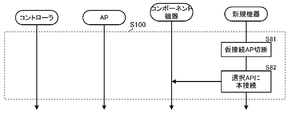
- FIG. 8 is a diagram showing a communication procedure when the new device disconnects the temporarily connected internal access point 4A in S75 and reconnects to another internal access point 4A in the tree.
- another internal access point 4A is selected as the connection destination of the main connection in S75 of FIG. 7
- the currently temporarily connected internal access point 4A is disconnected (S81), and system information is sent to the selected internal access point 4A.
- the main connection is made using the address information (S82). Thereafter, the process proceeds to S76 in FIG.
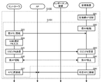
- FIG. 9 is a diagram showing a communication procedure when the new device disconnects the temporarily connected internal access point 4A in S75 and reconnects to the external access point 3 as a branch device.
- the external access point 3 is selected as the connection destination for this connection in S75 of FIG. 7, the currently temporarily connected internal access point 4A is disconnected (S91), and the temporary access point only at the initial connection is standalone.
- Start up S92
- the controller 1 stores in advance the SSID and password of this initial connection temporary access point. That is, the SSID and password are written as data in the audio system control program 70 in advance.
- the controller 1 finds this temporary access point in the new device search started in S53, once disconnects from the external access point 3, and connects to the temporary access point where the new device is activated (S83). ). Since it is highly likely that the controller 1 cannot acquire the SSID and password of the external access point 3 from the system program of the mobile phone 1, the controller 1 requests the user to input the SSID and password of the external access point 3 (S84). ).
- the SSID may be input by displaying a list of connection destinations (SSIDs) visible at that time on the display and allowing the user to select the SSID of the external access point 3.
- the password (usually written on the main body of the external access point 3) is input by the user.
- the input connection information is transmitted to the new device that has activated the temporary access point (S85).
- the new device receives this connection information (S93).
- the controller 1 cancels the connection with the temporary access point (S86).
- the new device receives the connection information of the external access point 3 from the controller 1, the new device stops the temporary access point (S94).
- the controller 1 connects again to the external access point 3 once disconnected (S87).
- the new device is also connected to the external access point 3 using the acquired connection information (S95). Thereafter, returning to the procedure of FIG. 7, the controller 1 searches for a new device (S53), and the new device responds (S76).
- S101 S83-S87, S92-94
- the root device 4-1 periodically transmits system information (once every 2 seconds) to other audio devices (component devices) 4 of the audio system 10.
- System information includes the MAC address (IP side) of each component device, the IP address, the number of connection stages from the root device 4-1 (the number of HOPs), whether or not the internal access point is activated, and the connection to the internal access point 4A It consists of the number of subordinate devices and connection information of the external access point 3.
- the root device 4-1 transmits this system information as an echo request packet (ping) to each component device.
- ping echo request packet
- this packet is referred to as a system information packet.
- the root device 4-1 creates a system information packet based on its own system management table (S111).
- the system information packet is configured as an IP packet including a UDP datagram having the system information shown in FIG. 10B as a data body, and the destination address of the IP header is set for the audio system 10. Multicast address that has been written is written.
- the root device 4-1 transmits a system information packet to the multicast address assigned to the audio system 10.
- each component device Upon receipt of the system information packet, each component device updates its own system information with the system information included in this packet, and indicates that the root device 4-1 has received the system information packet.
- a response packet (ACK) is returned.
- the root device 4-1 receives the response packet from the component device (S113), and determines whether there is a reply from all the component devices (S114). If there is a reply from all the component devices (YES in S114), this process is terminated as it is. If there is a component device that does not respond (NO in S114), the component device is rewritten to inactive and the system management table is updated (S115). The next generation of the system information packet is performed with the contents of the updated system management table. Therefore, each component device can always acquire the latest system information. Note that the contents of the updated management table are also notified to the controller 1. In the description of FIGS. 10A and 10B, the system information is transmitted by multicast, but may be individually transmitted to each component device by unicast.
- a situation in which the component device cannot return an ACK to the root device 4-1 is a device higher in the tree if the device has a cause such as the device being turned off (the outlet is disconnected). May be caused by a higher-level device, such as the power is turned off (the outlet is unplugged) or the communication radio wave condition is poor.
- Component devices (particularly node devices and leaf devices) automatically search for other connectable access points when communication with higher-level component devices (internal access point 4A) is disconnected from higher-level component devices. Try reconnecting with.
- the disconnection of communication with the upper internal access point 4A is, for example, that the above-mentioned system information packet has not been transmitted, or an encryption key update notification that is a procedure for maintaining Wi-Fi communication. Can be determined based on the fact that no message is sent or that there is no reply to the keep-alive packet.
- the component device disconnected from the upper internal access point 4A (hereinafter referred to as a disconnected device) stops its own internal access point 4A (S120). If the internal access point 4A is connected to a lower-level component device, the communication is disconnected and the lower-level component device also starts this operation.
- the disconnected device searches for connectable access points (S121). This search is performed by an active scan for the internal access point 4A described in the system information based on the system information held by the disconnected device at that time. Since connection is attempted based on the system information, it is possible to connect to the access point 4A without releasing the stealth mode. Temporary connection is made to the nearest internal access point 4A discovered by this search (S123). This connection is a temporary connection for acquiring the latest system information, and is not a main connection for returning to the audio system 10. Then, the latest system information of the audio system 10 is acquired from the connected internal access point 4A (component device) (S131, S123). The disconnecting device selects an optimal access point for reconnecting to the audio system 10 based on the acquired system information (S124).
- the disconnecting device disconnects the temporarily connected internal access point 4A (S125), and selects the selected access point.
- the main connection is made (S126).
- the access point to be connected is not limited to the internal access point 4A. Even in the case of the external access point 3, the connection information is often included in the system information. If it is determined that the currently temporarily connected internal access point 4A is the optimum reconnection destination, the steps S125 and S126 are not performed.
- the disconnected device transmits reconnection information including information of a reconnection destination access point to the root device 4-1.
- the root device 4-1 receives this reconnection information (S 132), rewrites this component device to be active, and updates the system management table (S 133).
- the updated contents are distributed to each component device when the next system information packet is transmitted (FIGS. 10A and 10B).
- the procedure for changing the connection destination from the disconnection of the component device to the reconnection will be described.
- the number of component devices of the audio system 10 is one less than that in the example of FIG. 1, and one leaf device 4-7 is connected to the node device 4-3.
- FIG. 12 shows a scene in which communication between the internal access point 4A-1 of the root device 4-1 and the node device 4-3 is disconnected due to deterioration of radio wave conditions or the like. Communication between the internal access point 4A-1 of the route device 4-1 and the node device 4-2 is maintained.
- the audio device 4-3 that is no longer a node device disconnects communication with the lower-level leaf device 4-7, and itself communicates with the nearest node device 4-2 based on the system information held at that time. Reconnect.
- the audio device 4-3 acquires the latest system information from the node device 4-2, but since the two leaf devices 4-4 and 4-5 are already connected to the node device 4-2, This node device 4-2 cannot be permanently connected. Therefore, the audio device 4-3 selects the external access point 3 as another connectable access point based on the system information, and becomes a branch device by connecting to the external access point 3 as shown in FIG. .
- communication with the internal access point 4A-1 of the root device 4-1 is restored, it may be reconnected to the root device 4-1.
- the audio device 4-7 which is a leaf device, reconnects to the nearest node device 4-2 based on the system information held at that time.
- the audio device 4-7 acquires the latest system information from the node device 4-2, but since the two leaf devices 4-4 and 4-5 are already connected to the node device 4-2, this This connection cannot be made to the node device 4-2. Therefore, the audio device 4-7 selects the external access point 3 as another connectable access point based on the latest system information, and connects to the external access point 3 as shown in FIG. It becomes.
- the number of tree hierarchies is limited to three, and the number of lower-level devices connectable to each audio device 4 is limited to two. Therefore, the reconnection mode as shown in FIGS. However, if the number of hierarchies and the number of sub-connections are larger, reconnection may be possible with trees having different shapes.
- the audio device of this disclosure may be an audio / visual (AV) device having a video reproduction function, and includes a system in which these are mixed.
- the control terminal device is realized by the mobile phone 1 in which the audio system control program 70 (application program) is installed, but other configurations may be used.
- the audio system control program 70 may be installed on a tablet terminal, or a dedicated terminal device may be used.
- a communication system includes a plurality of communication devices that are communicably connected to each other so as to configure a network, and each of the plurality of communication devices functions as a wireless relay device of the network.
- each of the plurality of communication devices functions as a wireless relay device of the network.
- 1 wireless communication unit and a second wireless communication unit functioning as a slave unit connected to other communication devices in the network, wherein the second wireless communication unit of the lower communication device is the first wireless of the higher communication device
- the higher-level communication device and the lower-level communication device are connected to form the network
- each of the plurality of communication devices includes a first wireless communication of each communication device that forms the network.
- System information including connection information to the communication unit, and when any one of the plurality of communication devices is disconnected from a higher-level communication device being connected, Cross communication equipment, using said system information Search for other communication devices making up the network, to reconnect to the detected communication device by the search is a communication system.
- the system information is periodically updated in the network, and the disconnected communication device is based on the system information stored at the time of disconnection. Temporarily connect to one communication device, acquire the latest system information from the temporarily connected communication device, determine a communication device to be permanently connected based on the acquired system information, and make a main connection to the determined communication device .
- the first wireless communication unit operates as an access point in a stealth mode
- the disconnected communication device searches for the other communication device by active scan using connection information acquired from the system information.
- each of the plurality of communication devices is multicast to another communication device of the plurality of communication devices.
- the system information is transmitted.
- the communication device is an audio device.
- the wireless relay device is a wireless router or a wireless access point.
- a communication device having a small number of connection stages from a root device in a connection form of a plurality of communication devices constituting the network is a higher-level communication.
- a communication device having a larger number of connection stages from the root device than the upper communication device is a lower communication device.
- the system information includes identification information of the communication system, identification information of the communication device, and identification information of a communication device as a connection destination.
- a communication device includes: a first wireless communication unit that functions as a wireless relay device of a network; a second wireless communication unit that functions as a slave unit connected to another communication device in the network; and the network A storage unit that stores system information including connection information to the first wireless communication unit of another communication device that is configured; and a control unit, wherein the control unit is connected to the second wireless communication unit.
- Communication that, when disconnected from the first wireless communication unit of a higher-level communication device, searches for another communication device constituting the network using the system information and reconnects to another communication device detected by the search.
- Equipment
- the system information is periodically updated by the higher-level communication device, and the control unit is configured based on the system information stored at the time of disconnection. Temporarily connect to one communication device, acquire the latest system information from the temporarily connected communication device, determine a communication device to be permanently connected based on the acquired system information, and make a main connection to the determined communication device.
- control unit searches for the other communication device by active scan using connection information acquired from the system information.
- control unit transmits the system information to the other communication device by multicast.
- the communication device further includes an audio signal processing unit that processes an audio signal.
- the wireless relay device is a wireless router or a wireless access point.
- a communication device having a small number of connection stages from a route device in a connection form of a plurality of communication devices constituting the network is a higher-level communication.
- a communication device having a larger number of connection stages from the root device than the upper communication device is a lower communication device.
- the system information includes identification information of the communication system, identification information of the communication device, and identification information of a communication device as a connection destination.
- a plurality of communication devices are connected to form a network, and each of the plurality of communication devices functions as a wireless relay device of the network. And a second wireless communication unit that functions as a slave connected to another device in the network, and the second wireless communication unit of the lower communication device accesses the first wireless communication unit of the higher communication device.
- the higher-level communication device and the lower-level communication device are connected to configure the network, and each of the plurality of communication devices is connected to the first wireless communication unit of each communication device that configures the network.
- a reconnection method of a communication system storing system information including: whether any one of the plurality of communication devices is a higher-level communication device being connected
- the disconnected communication device searches for another communication device constituting the network using the system information, and reconnects to the communication device detected by the search. It is.
- the system information is periodically updated in the network, and the disconnected communication device is stored at the time of disconnection Temporarily connecting to one communication device based on the information, acquiring the latest system information from the temporarily connected communication device, determining the communication device to be permanently connected based on the acquired system information, and determining the determined communication device Connect to the main.
- the first wireless communication unit operates as a stealth mode wireless relay device
- the disconnected communication device is The other communication device is searched by active scan using connection information acquired from the system information.
- the system information is transmitted by multicast within the network.
- the communication device is an audio device.
- the wireless relay device is a wireless router or a wireless access point.
- a communication device having a small number of connection stages from a root device in a connection form of a plurality of communication devices constituting the network Is a higher-level communication device, and a communication device having a larger number of connection stages from the root device than the higher-level communication device is a lower-level communication device.
- the system information includes identification information of the communication system, identification information of the communication device, and communication at a connection destination.
- Device identification information IP address of the connection destination communication device, number of connection stages from the root device in the connection form of a plurality of communication devices constituting the network, presence / absence of activation of the first wireless communication unit as a wireless relay device , At least one of the number of connected lower-level communication devices and the communication operating state.
- the communication device can be easily reconnected to the network, which is useful.
Landscapes
- Engineering & Computer Science (AREA)
- Computer Networks & Wireless Communication (AREA)
- Signal Processing (AREA)
- Mobile Radio Communication Systems (AREA)
- Reverberation, Karaoke And Other Acoustics (AREA)
- Computer And Data Communications (AREA)
Abstract
通信システム(10)は、ネットワークを構成するように相互に通信可能に接続された複数の通信機器(4)を備える。前記複数の通信機器のそれぞれは、前記ネットワークの無線中継装置として機能する第1無線通信部(57)と、前記ネットワークにおける他の通信機器に接続する子機として機能する第2無線通信部(56)と、を備え、下位の通信機器の第2無線通信部が上位の通信機器の第1無線通信部にアクセスすることで、該上位の通信機器及び下位の通信機器が前記ネットワークを構成するよう接続され、前記複数の通信機器のそれぞれは、前記ネットワークを構成する各通信機器の第1無線通信部への接続情報を含むシステム情報を記憶し、前記複数の通信機器のうちのいずれかの通信機器が接続中の上位の通信機器から切断されたとき、この切断された通信機器は、前記システム情報を用いて前記ネットワークを構成する他の通信機器を検索し、検索によって検出された通信機器に再接続する。
Description
この開示は、複数のオーディオ機器(通信機器)をネットワークで接続したオーディオシステム(通信システム)に関する。
複数のオーディオ機器からなるオーディオシステムにおいて、従来は、各オーディオ機器は、アナログまたはデジタルのオーディオケーブルで互いに接続されていた。近年、煩雑なケーブル群を無くすとともに接続形態の自由度を高めるために、各機器をネットワーク(特に無線ネットワーク)で接続し、パケットで音声信号やコマンドメッセージを送受信することが考えられている。
オーディオケーブルは全ての入出力毎にそれぞれ必要であるものの、機器の端子に物理的に接続すれば接続が完了する。これに対して、無線ネットワークは、たとえば特許文献1に示すように、SSIDやパスワードなどの設定が必要であり、設定作業がケーブルの接続よりも複雑である。また、接続先のアクセスポイントが停止した場合などは接続先を変更して再接続する必要があるが、この作業も最初の接続時と同様に面倒であった。
そこで本開示の目的は、ネットワークを用いて複数の通信機器を接続する通信システムで、通信機器がネットワークから切断されても自動で再接続できるようにすることにある。
(1)本開示の通信システムは、
ネットワークを構成するように相互に通信可能に接続された複数の通信機器を備え、
前記複数の通信機器のそれぞれは、前記ネットワークの無線中継装置として機能する第1無線通信部と、前記ネットワークにおける他の通信機器に接続する子機として機能する第2無線通信部と、を備え、
下位の通信機器の第2無線通信部が上位の通信機器の第1無線通信部にアクセスすることで、該上位の通信機器及び下位の通信機器が前記ネットワークを構成するよう接続され、
前記複数の通信機器のそれぞれは、前記ネットワークを構成する各通信機器の第1無線通信部への接続情報を含むシステム情報を記憶し、
前記複数の通信機器のうちのいずれかの通信機器が接続中の上位の通信機器から切断されたとき、この切断された通信機器は、前記システム情報を用いて前記ネットワークを構成する他の通信機器を検索し、検索によって検出された通信機器に再接続する、
通信システムである。
ネットワークを構成するように相互に通信可能に接続された複数の通信機器を備え、
前記複数の通信機器のそれぞれは、前記ネットワークの無線中継装置として機能する第1無線通信部と、前記ネットワークにおける他の通信機器に接続する子機として機能する第2無線通信部と、を備え、
下位の通信機器の第2無線通信部が上位の通信機器の第1無線通信部にアクセスすることで、該上位の通信機器及び下位の通信機器が前記ネットワークを構成するよう接続され、
前記複数の通信機器のそれぞれは、前記ネットワークを構成する各通信機器の第1無線通信部への接続情報を含むシステム情報を記憶し、
前記複数の通信機器のうちのいずれかの通信機器が接続中の上位の通信機器から切断されたとき、この切断された通信機器は、前記システム情報を用いて前記ネットワークを構成する他の通信機器を検索し、検索によって検出された通信機器に再接続する、
通信システムである。
本開示の通信機器は、
ネットワークの無線中継装置として機能する第1無線通信部と、
前記ネットワークにおける他の通信機器に接続する子機として機能する第2無線通信部と、
前記ネットワークを構成する他の通信機器の第1無線通信部への接続情報を含むシステム情報を記憶する記憶部と、
制御部と、
を備え、
前記制御部は、前記第2無線通信部が、接続中の上位の通信機器の第1無線通信部から切断されたとき、前記システム情報を用いて前記ネットワークを構成する他の通信機器を検索し、検索によって検出された他の通信機器に再接続する、
通信機器である。
ネットワークの無線中継装置として機能する第1無線通信部と、
前記ネットワークにおける他の通信機器に接続する子機として機能する第2無線通信部と、
前記ネットワークを構成する他の通信機器の第1無線通信部への接続情報を含むシステム情報を記憶する記憶部と、
制御部と、
を備え、
前記制御部は、前記第2無線通信部が、接続中の上位の通信機器の第1無線通信部から切断されたとき、前記システム情報を用いて前記ネットワークを構成する他の通信機器を検索し、検索によって検出された他の通信機器に再接続する、
通信機器である。
本開示の通信システムの再接続方法は、複数の通信機器がネットワークを構成して接続され、前記複数の通信機器のそれぞれが、前記ネットワークの無線中継装置として機能する第1無線通信部と、前記ネットワークにおける他の機器に接続する子機として機能する第2無線通信部と、を備え、下位の通信機器の第2無線通信部が上位の通信機器の第1無線通信部にアクセスすることで、該上位の通信機器及び下位の通信機器が前記ネットワークを構成するよう接続され、前記複数の通信機器のそれぞれが、前記ネットワークを構成する各通信機器の第1無線通信部への接続情報を含むシステム情報を記憶している通信システムの再接続方法であって、
前記複数の通信機器のうちのいずれかの通信機器が接続中の上位の通信機器から切断されたとき、この切断された通信機器は、前記システム情報を用いて前記ネットワークを構成する他の通信機器を検索し、検索によって検出された通信機器に再接続する、
通信システムの再接続方法。
前記複数の通信機器のうちのいずれかの通信機器が接続中の上位の通信機器から切断されたとき、この切断された通信機器は、前記システム情報を用いて前記ネットワークを構成する他の通信機器を検索し、検索によって検出された通信機器に再接続する、
通信システムの再接続方法。
この開示によれば、ネットワークに接続されていた通信機器が上位機器から切断された場合でも、他の通信機器を検索して自動で再接続することが可能になる。
図1は、本開示が適用されるオーディオシステムの構成を示す図である。オーディオシステム10は、有線LAN2およびアクセスポイント(外部アクセスポイント)3を含むネットワーク9で接続された複数のオーディオ機器4(4-1~4-8)、および、コントローラ1として機能する多機能携帯電話機1(以下、携帯電話機とする)を有している。各オーディオ機器4は、ネットワーク9を介して相互にオーディオ信号の送受信を行う。コントローラ1は、ネットワーク9を介してオーディオ機器4に対してコマンドメッセージを送信する。
オーディオシステム10を構成する各オーディオ機器4(以下、コンポーネント機器とも言う)は、有線LAN機能および2つの無線LAN機能を有している。オーディオ機器4は、2つの無線LAN機能の一方を用いてアクセスポイントを起動することができる。オーディオ機器4によって起動されたアクセスポイントは内部アクセスポイント4Aと呼ばれる。内部アクセスポイント4Aには、下位のオーディオ機器4が接続される。内部アクセスポイント4Aは、通常は(後述のイニシャル接続時以外は)ステルスモードで動作しており、他の機器にその存在を知られにくいようになっている。もう一方の無線LAN機能は、無線LANの子機として機能し、上位のオーディオ機器4の内部アクセスポイント4A、または、外部アクセスポイント3に接続される。
有線LAN2にはアクセスポイント(外部アクセスポイント)3が接続されている。オーディオ機器4-1は有線LAN2にケーブルで接続されている。オーディオ機器4-2,4-3は、上位のオーディオ機器4-1の内部アクセスポイント4A-1に無線LANで接続されている。オーディオ機器4-4,4-5は、上位のオーディオ機器4-2の内部アクセスポイント4A-2に無線LANで接続されている。また、オーディオ機器4-6,4-7は、上位のオーディオ機器4-3の内部アクセスポイント4A-3に無線LANで接続されている。オーディオ機器4-8は、外部アクセスポイント3に接続されている。
この実施形態において、ネットワーク9は、有線LAN2、および、外部アクセスポイント3、内部アクセスポイント4Aを含む無線LANで構成される。有線LAN2は、たとえばEthernet(登録商標:IEEE802.3)が用いられ、無線LANは、たとえばWi-Fi(IEEE802.11g)が用いられる。
各オーディオ機器4は、有線LAN2に対する接続の形態に応じてルート機器、ノード機器、リーフ機器、および、ブランチ機器と呼ばれる。ルート機器は、有線LAN2に直接(ケーブルで)接続されている最上位の機器であり、図1においてオーディオ機器4-1がルート機器である。ルート機器は、オーディオシステム10の構築時に最初に登録されたオーディオ機器であり、オーディオシステム10の基点となる。ルート機器は、下位のオーディオ機器4をネットワークに接続してオーディオシステム10に参加させるための内部アクセスポイント4Aを起動する。ルート機器以下に接続されているオーディオ機器4(ノード機器、リーフ機器)で再生される音楽情報は全てここを経由して送信されることになる。
ノード機器は、無線LANによってルート機器(ルート機器の内部アクセスポイント4A)に接続されている中位の機器であり、図1においてオーディオ機器4-2,4-3がノード機器である。ノード機器は、下位のオーディオ機器4をネットワークに接続してオーディオシステム10に参加させるための内部アクセスポイント4Aを起動する。ノード機器以下に接続されているオーディオ機器4(リーフ機器)で再生される音楽情報はここを経由して送信されることになる。
リーフ機器は、無線LANによってノード機器(ノード機器の内部アクセスポイント4A)に接続されている下位の機器であり、図1においてオーディオ機器4-4,4-5,4-6,4-7がリーフ機器である。なお、リーフ機器は、内部アクセスポイント4Aを起動しないが、起動するようにしてもよい。
ブランチ機器は、ルート機器を頂点とするツリーとは別に外部アクセスポイント3に無線LANで接続され有線LAN2を経由してオーディオシステム10内の他のオーディオ機器4と通信するオーディオ機器4であり、図1においては、オーディオ機器4-8がブランチ機器である。なお、ブランチ機器は、内部アクセスポイント4Aを起動しないが、起動するようにしてもよい。
このオーディオシステムでは、高品質のオーディオ信号の伝送のため、ルート機器には2台までのノード機器の接続が許可される。また、各ノード機器には2台までのリーフ機器の接続が許可される。また、内部アクセスポイント4Aを用いた接続の階層は、ルート機器-ノード機器-リーフ機器の3階層までとする。したがって、ルート機器を頂点とする無線LANのツリーにより、ルート機器を含めて7台までのオーディオ機器を接続することができる。図1に示したツリーには、接続可能数な最大数(7台)のオーディオ機器4(4-1~4-7)が接続されている。また、ブランチ機器の台数に制限はないが、コントローラ1の制御対象としては、オーディオシステム10全体でオーディオ機器4の台数が10台までに制限される。ただし本開示において、ツリーの階層の数、各オーディオ機器4に接続可能な下位の機器の台数などの最大数は、この実施形態に限定されない。
携帯電話機1はオーディオシステム制御プログラム70(図2参照)が起動されることによりオーディオシステムコントローラ(以下、コントローラ)1として機能する。携帯電話機1(コントローラ1)は、オーディオシステム10に所属するオーディオ機器4とネットワーク9を介して通信する。コントローラ1は、この通信により、そのオーディオシステム10内で再生されるオーディオソース(たとえば、どのオーディオ機器4でどの楽曲を再生するか、どの楽曲をどのオーディオ機器4に配信するかなど)やその音量などを制御する。また、各オーディオ機器4は、ネットワーク9を介して自己が所属するオーディオ機器4と通信し、相互にオーディオ信号を送受信する。
次に、図2のブロック図を参照して、携帯電話機1の構成を説明する。携帯電話機1は、いわゆるスマートフォンと言われる多機能電話機である。携帯電話機1は、携帯通信網である3G/4G通信機能、無線LAN(Wi-Fi)通信機能、および、Bluetooth(登録商標)通信機能を有している。携帯電話機1は、アプリケーションプログラムであるオーディオシステム制御プログラム70を起動することにより、コントローラ1として機能し、ネットワーク3経由でオーディオシステムのオーディオ機器4と通信し、ユーザの操作に応じたコマンドメッセージをオーディオ機器4に送信してオーディオシステムを制御する。
携帯電話機1は、バス26上に、制御部20、操作部30、メディアインタフェース31、無線LAN通信回路32、3G/4G通信回路33、および、Bluetooth(登録商標)通信を行うことが可能な近距離無線通信回路34を有している。制御部20は、CPU21、ROM(フラッシュメモリ)22、RAM23、画像プロセッサ24および音声プロセッサ25を含んでいる。画像プロセッサ24には、ビデオRAM(VRAM)40が接続され、VRAM40には表示部41が接続されている。表示部41は液晶のディスプレイを含んでいる。ディスプレイには、待ち受け画面や電話番号などが表示される。また、コントローラ1として機能する場合は、オーディオ機器4を制御するための画面が表示される。音声プロセッサ25には、D/Aコンバータを含むアンプ42が接続され、アンプ42にはスピーカ16が接続されている。
画像プロセッサ24は、待ち受け画面や電話番号等などの種々の映像を生成するGPU(Graphics Processing Unit)を備えている。画像プロセッサ24は、オーディオシステム制御プログラム70が起動された場合には、CPU21の指示に従ってオーディオコントローラの画像を生成し、これをVRAM40上に展開する。VRAM40上に展開された画像は表示部41に表示される。
音声プロセッサ25は、通話音声をエンコード/デコードするDSP(Digital Signal Processor)を有している。音声プロセッサ25は、デコード/生成した音声をアンプ42に出力する。アンプ42は、この音声信号を増幅してスピーカ16に出力する。
無線LAN通信回路32は、ルータとの間でIEEE802.11gなどの規格で無線通信を行い、アクセスポイント3,7を介してオーディオ機器4と通信する。3G/4G通信回路33は、携帯電話通信網を介して、音声通話およびデータ通信を行う。近距離無線通信回路34は、他のBluetooth(登録商標)対応機器と通信し、例えばオーディオ信号の送受信等を行う。
操作部30は、表示部41上に形成されたタッチパネルを含み、タッチパネル上のタッチ操作、フリック操作を検出する。オーディオシステム制御プログラム70が起動されると、表示部41には、セットアップボタン、スキャンボタンなどの複数の操作子が表示される。操作部30は、タッチパネルでユーザのタッチ操作およびその座標を検出し、どの操作子が操作されたかを判断する。
メディアインタフェース31にはメモリカード15が接続される。メモリカード15は、たとえばマイクロSDカードである。オーディオシステム制御プログラム70は、メモリカード15またはROM22に保存される。この実施形態では、図2に示したように、オーディオシステム制御プログラム70はメモリカード15に保存されるものとする。なお、オーディオシステム制御プログラム70は、3G/4Gまたは無線LANのデータ通信によってダウンロードされてもよく、ROM22またはメモリカード15に予め記憶されていてもよい。また、メモリカード15には、オーディオシステムの構成を記憶する記憶エリア71が設定される。
ROM22には、この携帯電話機1の通話やアプリケーションプログラムを実行するための基本プログラムが記憶されている。また、ROM22はフラッシュメモリであり、基本プログラムのほか、ダウンロードされたアプリケーションプログラムなどを記憶することも可能である。RAM23には、CPU20がオーディオシステム制御プログラム70を実行する際に使用されるワークエリアが設定される。
次に図3を参照してオーディオ機器4の構成について説明する。オーディオ機器4は、制御部50、オーディオ処理部51および操作部59を有するとともに、2つの無線LAN通信部(RFモジュール)56、57および有線LAN通信部58を有している。操作部59はボリューム操作子(不図示)の他、コネクトボタン59Aを有している。制御部50は、CPUおよびメモリを含み、オーディオシステムプログラムを記憶している。制御部50は、オーディオシステムプログラムにより、オーディオ処理部51および無線LAN通信部56、57、有線LAN通信部58の動作を制御する。また、制御部50は、コネクトボタン59Aが押下されたとき、このオーディオ機器4をネットワーク9に接続するための動作であるイニシャル接続動作を実行する。イニシャル接続動作の詳細は後述する。
無線LAN通信部56は、IEEE802.11gなどの無線LAN規格で外部アクセスポイント3または上位オーディオ機器4の内部アクセスポイント4Aと無線通信を行う。また、もう一つの無線LAN通信部57は、アクセスポイント(内部アクセスポイント4A)として起動され、他のオーディオ機器(たとえばオーディオ機器4-2,4-3など)を有線LAN2に中継する。また、無線LAN通信部57は、このオーディオ機器4のイニシャル接続時にもイニシャル接続用の仮アクセスポイントとして起動され、コントローラ1(携帯電話機1)と通信する。イニシャル接続時の動作は後述する。なお、2つの無線LAN通信部56、57は、1つのハードウェアを時分割で動作させて実現してもよい。有線LAN通信部58は、ケーブルコネクタを有し、IEEE802.3などの通信規格で有線LAN2-アクセスポイント3を介した通信を行う。アクセスポイント3には、コントローラ(携帯電話機)1が接続されており、制御部50は、ネットワーク9を経由してコントローラ1と通信し、動作状態を送信したり、コマンドメッセージを受信したりする。
内部アクセスポイント4AのSSIDおよびパスワードは、無線LAN通信部57のMACアドレスから割り出し可能な文字列にされている。たとえば、MACアドレスをオクテット表現したものをSSIDとし、下3オクテット(機種ID+シリアル番号)をパスワードとするなどである。これにより、新たにオーディオシステムに参加するオーディオ機器は、SSIDに基づいて、すなわち、MACアドレスのベンダーIDおよび機種IDに基づいて、内部アクセスポイント4Aを発見することができ、且つ、自らパスワードを生成してその内部アクセスポイント4Aに接続することができる。これにより、内部アクセスポイント4Aに接続する場合の、ユーザによるSSID、パスワードの入力を省略することができる。なお、内部アクセスポイント4AのSSID、パスワードの生成方式は上記のものに限定されない。
オーディオ処理部51は、チューナ52、オーディオ回路53、パワーアンプ54を有している。チューナ52は、FM放送またはインターネットからオーディオ信号を受信してオーディオ回路53に入力する。オーディオ回路53は、入力されたオーディオ信号に対してイコライズ、音量調整などの処理を行ったのち、この処理されたオーディオ信号をパワーアンプ54に出力する。パワーアンプ54は入力されたオーディオ信号を増幅し、外部接続されているスピーカ55に出力する。スピーカ55は、入力されたオーディオ信号を音響として放音する。
なお、オーディオ機器4-1~4-8は、それぞれ異なる機器であってよいが、通信機能およびオーディオ信号処理機能の基本的な構成は図3に示したものである。
図4、図5は、オーディオシステムを管理するテーブルの一例を示す図である。図4は、ネットワーク9における各オーディオ機器4の接続形態を管理するシステム管理テーブルである。また、図5は、オーディオシステム10における各オーディオ機器4の動作を管理するオーディオ制御テーブルである。システム管理テーブルは、主としてルート機器4-1によってネットワーク接続の管理に用いられる。また、オーディオ制御テーブルは、主としてコントローラ1によって、オーディオソースの再生制御に用いられる。
システム管理テーブルは、オーディオシステム10を構成する各オーディオ機器4(コンポーネント機器)の接続形態を記憶したものであり、オーディオシステム10の構築時にコントローラ1が作成する。また、オーディオシステム10へ新たなオーディオ機器4が追加されたとき、コントローラ1がこのオーディオ機器4を追加する更新を行う。作成または追加更新されたシステム管理テーブルは、コントローラ1からルート機器4-1に送信される。その後、システム管理テーブルは、オーディオシステム10の動作中に、いずれかのコンポーネント機器の切断または再接続が発生するごとに、ルート機器4-1よって更新される。また、ルート機器4-1は、定期的にシステム管理テーブルの内容の全部または一部をシステム情報として各コンポーネント機器およびコントローラ1に送信する。これにより、各コンポーネント機器およびコントローラ1は常に最新のシステム情報を保持することができる。以上のシステム情報の送信の詳細動作については後述する。
システム管理テーブルは、このオーディオシステム10を識別するためのシステムIDで識別される。各コンポーネント機器は、各機器の機器IDに対応づけて、上位側(子機側)/下位側(内部アクセスポイント側)のMACアドレス(すなわち無線LAN通信部56/57のMACアドレス)、上位側/下位側のIPアドレス(すなわち無線LAN通信部56/57のIPアドレス)、ルート機器4-1からの接続段数(HOP数)、内部アクセスポイントの起動の有無、内部アクセスポイント4Aに接続している下位機器の数(Child数)、および、動作状態(通信可/不可)情報(Active)などの情報を記憶している。いずれかのコンポーネント機器がルート機器4-1から切断されると(通信が途絶えると)、その機器の欄を非アクティブ(通信不可能)とし、再接続されると、再接続された内容で更新して再度アクティブ化する。以上の切断、再接続に関する動作の詳細は後述する。
なお、各コンポーネント機器は、個別のIPアドレスを有しているが、このオーディオシステム10は、マルチキャストグループとしてマルチキャストアドレスが設定されている。このマルチキャストアドレス宛に上記のシステム情報のIPパケットを送信することにより、オーディオシステム10の全コンポーネント機器にこのシステム情報パケットを受信させることができる。なお、システム情報パケットを各コンポーネント機器のIPアドレス宛にユニキャストで送信してもよいが、マルチキャストで送信することによりネットワーク9の負荷を小さくすることができる。
図5のオーディオ制御テーブルは、各機器の機器IDに対応づけて、各コンポーネント機器の上位側IPアドレス(無線LAN通信部56のIPアドレス)、機種、設置場所、動作状態情報、および、ボリューム値、表示名称などの各種設定情報が記憶される。オーディオ制御テーブルの各欄とシステム管理テーブルの各欄とは機器IDで対応づけられる。コントローラ1は、このオーディオ制御テーブルの内容に基づいてコントロール画面を作成し、ユーザによる各コンポーネント機器の制御を受け付ける。
オーディオシステム10を構築する場合、最初にルート機器4-1を設定してオーディオシステム10を構築する。その後、このオーディオシステム10にルート機器4-1以外のオーディオ機器4を追加してゆく。ユーザは、以下の手順で作業する。ルート機器となるオーディオ機器4-1を有線LAN2にケーブルに接続する。携帯電話機1上でコントローラ1をセットアップモードで起動する。オーディオ機器4-1のコネクトボタン59Aを押下する。ユーザが以上の作業を行えば、コントローラ1とルート機器4-1は、相互に通信し、自動でオーディオシステム10を構築する。その後、オーディオシステム10に新たなオーディオ機器4を追加する場合、ユーザは、コントローラ1をセットアップモードで起動し、追加するオーディオ機器4の電源をオンして(無線LAN通信部56,57を起動して)、コネクトボタン59Aを押下すれば、そのオーディオ機器4は、コントローラ1およびルート機器4-1と通信し、上述のSSIDからパスワードを自動生成することで、自動でオーディオシステム10に追加される。
図6~図9を参照して、オーディオシステム10の構築時、および、オーディオシステム10へのオーディオ機器4の追加時におけるコントローラ1とオーディオ機器4との通信手順について説明する。
図6は、新規にオーディオシステム10を構築する場合のコントローラ1とルート機器となるオーディオ機器4-1との通信手順を示す図である。携帯電話機1は、オーディオシステム制御プログラム70が起動されて、コントローラ1として機能している。ユーザの操作によってコントローラ1がセットアップモードになると(S31)、表示部41にオーディオ機器4のコネクトボタン59Aを押下することを促す案内画面が表示される。この画面の案内に従いユーザはオーディオ機器4-1のコネクトボタン59Aを押下する(S41)。次に、コントローラ1は、有線LAN2に接続された新規のオーディオ機器を検索する(S32)。この検索はポーリングなど返信を要求するメッセージを送信することで行われる。オーディオ機器4-1は、この検索に対して応答する(S42)。これにより、コントローラ1とオーディオ機器4-1は、有線LAN2,アクセスポイント3を介して相互通信を開始する。
オーディオ機器4-1は、自分自身の機器情報(無線LAN通信部のMACアドレスやIPアドレスなど)をコントローラ1に送信する(S43)。コントローラ1は、このオーディオ機器4-1をルート機器とする新規のオーディオシステム10を構築する。オーディオシステム10にシステムIDを割り当て(S34)、図4、図5に示すシステム管理テーブルおよびオーディオ制御テーブルを作成して、現在通信しているオーディオ機器4をルート機器とするオーディオシステム10を構築する(S35)。オーディオシステム10が構築されると、システム管理テーブルをルート機器となったオーディオ機器4-1に送信し(S36)、セットアップモードを終了する(S37)。オーディオ機器4-1はこのシステム管理テーブルを受信して(S44)、保存する(S45)。これにより、オーディオ機器4-1を基幹の構成要素(コンポーネント)であるルート機器とするオーディオシステム10が構築される。以後は、コントローラ1によって、再生楽曲やその音量などを制御されるようになる。オーディオ機器4は、ステルスモードでアクセスポイントを起動する(S46)。
図7は、構築済みのオーディオシステム10に、新たなオーディオ機器が追加される場合の通信手順を示す図である。コンポーネント機器は、既にオーディオシステム10の構成要素となっているオーディオ機器4であり、ここでは、内部アクセスポイント4Aを起動しているルート機器またはノード機器である。新規機器は、これから新たに追加されるオーディオ機器4である。
コントローラ1として機能している携帯電話機1が、ユーザの操作によってセットアップモードになる(S51)と、表示部41にオーディオ機器4(新規機器)のコネクトボタン59Aを押下することを促す案内画面が表示される。この画面の案内に従いユーザは新規機器のコネクトボタン59Aを押下する(S71)。コントローラは、既に登録されているオーディオ機器4であるコンポーネント機器に、内部アクセスポイント4Aのステルスモードを解除するよう指示する(S52)。これによりコンポーネント機器は、内部アクセスポイント4Aのステルスモードを解除し、自己の存在を知らせるビーコンフレームを送信して新規機器のパッシブスキャンを可能にする(S61)。次に、コントローラ1は、新規機器の検索を開始する(S53)。
新規機器は、ユーザによってコネクトボタン59Aが押下されると(S71)、イニシャル接続モードになり、接続可能なアクセスポイントを検索(パッシブスキャン)する(S72)。この検索で、新規機器は、接続可能なアクセスポインとして、コンポーネント機器の内部アクセスポイント4Aを発見する。上述したように、内部アクセスポイント4Aは、新規機器から見てオーディオシステム10の機器であることを識別可能なSSIDを有しており、かつ、そのSSID(またはMACアドレス)からパスワードを生成して接続可能である。新規機器は、発見した内部アクセスポイント4Aのなかから最寄りの(最も接続しやすい)ものを選択し、このSSIDおよび生成したパスワードを用いて、選択した内部アクセスポイント4Aに仮接続する(S73)。この接続は、システム情報を取得するための仮接続であり、オーディオシステム10に参加するための本接続ではない。そして、接続した内部アクセスポイント4A(コンポーネント機器)からオーディオシステム10の現時点でのシステム情報を取得する(S62、S74)。システム情報は、システム管理テーブルの全部または一部の内容からなる情報であり、定期的にルート機器4-1が更新して他のコンポーネント機器に配信される。新規機器は、取得したシステム情報に基づいて、オーディオシステム10に参加するために最適のアクセスポイントを選択する(S75)。この選択は、各アクセスポイントの電波強度、ルート機器4-1からの接続段数、そのアクセスポイントに接続されているコンポーネント機器の数などに基づいて行われ、通信条件がよさそうなアクセスポイントが選択される。
図7の例(S100が実行されない例)では、仮接続した内部アクセスポイント4Aが本接続においても最適であると判断し、接続先を変更しない場合の流れを示している。たとえば、ルート機器4-1の内部アクセスポイント4A-1に接続されている場合等がこれに相当する。本接続で仮接続の内部アクセスポイント4Aから接続先を変更する場合には、図7に示すS100の区間で図8または図9の手順が実行される。本接続が完了すると(図7の場合には仮接続を本接続としたのち)、新規機器は、コントローラ1からの新規機器検索メッセージ(S53)を受信し、これに対して応答する(S76)。これで新規機器は、コントローラ1と通信可能になる。これにより、新規機器は、コントローラ1によって再生する楽曲やその音量などが制御されるようになり、オーディオシステム10の構成要素(コンポーネント)となる。
新規機器は、自分自身の機器情報(無線LAN通信部のMACアドレスやIPアドレスなど)をコントローラ1に送信する(S77)。コントローラ1は、この機器情報を受信し(S54)、システム管理テーブルおよびオーディオ制御テーブルにこの新規オーディオ機器4を登録してこれらを更新する(S55)。コントローラ1は、更新したシステム管理テーブルをルート機器4-1に送信して(S56)、セットアップモードを終了する(S57)。ルート機器4-1は、システム管理テーブルの全部または一部の内容からなるシステム情報を、図10(A)、(B)で説明する接続確認メッセージとして、定期的に他のコンポーネント機器に配信する。セットアップモード終了の通知はコントローラ1から全てのオーディオ機器4に送信されるが、コントローラ1がルート機器4-1に対して行い、ルート機器4-1がオーディオシステム10の他のオーディオ機器4に転送するようにしてもよい。
ルート機器4-1からシステム情報を受信した新規機器は、このシステム情報を保存する(S78)。こののち新規機器は、ステルスモードで内部アクセスポイント4Aを起動する(S79)。また、ルート機器4-1からシステム情報を受信したコンポーネント機器は、この情報で内部に記憶しているシステム情報を更新する(S63)。そして、内部アクセスポイント4Aをステルスモードに戻す(S64)。以上の処理により、構築済みのオーディオシステム10に新たな機器を追加することができる。なお、コンポーネント機器、新規機器ともに、ステルスモードで内部アクセスポイント4Aを立てるのは、ルート機器、ノード機器のみであり、リーフ機器、ブランチ機器ではS64、S79の処理は行われない。
図8は、新規機器が、S75で仮接続の内部アクセスポイント4Aを切断して、ツリー内の他の内部アクセスポイント4Aに接続し直す場合の通信手順を示す図である。図7のS75で本接続の接続先として他の内部アクセスポイント4Aが選択されると、現在仮接続している内部アクセスポイント4Aを切断し(S81)、選択された内部アクセスポイント4Aにシステム情報のアドレス情報を用いて本接続する(S82)。こののち、図7のS76に進む。
図9は、新規機器が、S75で仮接続の内部アクセスポイント4Aを切断して、外部アクセスポイント3にブランチ機器として接続し直す場合の通信手順を示す図である。図7のS75で本接続の接続先として外部アクセスポイント3が選択されると、現在仮接続している内部アクセスポイント4Aを切断し(S91)、イニシャル接続時のみの仮アクセスポイントをスタンドアローンで起動する(S92)。すなわち、有線LAN2には接続されず新規機器に接続されるのみの内部アクセスポイント4Aを起動する。コントローラ1は、このイニシャル接続仮アクセスポイントのSSIDおよびパスワードを予め記憶している。すなわち、このSSIDおよびパスワードは、オーディオシステム制御プログラム70に予めデータとして書き込まれている。したがって、コントローラ1は、S53で開始した新規機器検索の中でこの仮アクセスポイントを発見し、外部アクセスポイント3との接続を一旦解除して、新規機器が起動した仮アクセスポイントに接続する(S83)。コントローラ1は、携帯電話機1のシステムプログラムから外部アクセスポイント3のSSID、パスワードを取得することができない可能性が高いため、ここでは、ユーザに外部アクセスポイント3のSSIDおよびパスワードの入力を求める(S84)。SSIDの入力は、そのとき見えている接続先(SSID)の一覧をディスプレイに表示し、ユーザに外部アクセスポイント3のSSIDを選択させる方式でよい。パスワード(通常は外部アクセスポイント3の本体に表記されている)は、ユーザに入力させる。
そして、この入力された接続情報を、仮アクセスポイントを起動している新規機器に送信する(S85)。新規機器がこの接続情報を受信する(S93)。コントローラ1は、新規機器に外部アクセスポイント3の接続情報(SSID,パスワード)を送信したのち、仮アクセスポイントとの接続を解消する(S86)。新規機器は、外部アクセスポイント3の接続情報をコントローラ1から受信すると、仮アクセスポイントを停止する(S94)。コントローラ1は、一旦接続を解除した外部アクセスポイント3に再度接続する(S87)。新規機器も取得した接続情報を用いて外部アクセスポイント3に接続する(S95)。こののち図7の手順にもどって、コントローラ1は新規機器検索を行い(S53)、新規機器はこれに応答する(S76)。なお、仮接続したコンポーネント機器から取得したシステム情報に外部アクセスポイント3の接続情報が含まれている場合は、S101で示した処理(S83-S87、S92-94)を省略して図8と同じように外部アクセスポイントに接続し直せばよい。
上述したように、ルート機器4-1は、オーディオシステム10の他のオーディオ機器(コンポーネント機器)4に対して、定期的に(2秒に1回)システム情報を送信する。システム情報は、各コンポーネント機器の(内部アクセスポイント側)MACアドレス、IPアドレス、ルート機器4-1からの接続段数(HOP数)、内部アクセスポイントの起動の有無、内部アクセスポイント4Aに接続している下位機器の数、および、外部アクセスポイント3の接続情報などからなる。ルート機器4-1は、このシステム情報をエコー要求パケット(ping)として、各コンポーネント機器に送信する。以下、このパケットをシステム情報パケットと呼ぶ。
図10(A)、(B)を参照して、定期的に実行されるシステム情報パケットの送信処理について説明する。図10(A)において、ルート機器4-1は、自己のシステム管理テーブルに基づきシステム情報パケットを作成する(S111)。システム情報パケットは、図10(B)に示すシステム情報をデータ本体とするUDPデータグラムを内包するIPパケットの構成をしており、IPヘッダの宛先アドレスには、このオーディオシステム10に対して設定されているマルチキャストアドレスが書き込まれている。ルート機器4-1は、システム情報パケットをこのオーディオシステム10に対して付与されたマルチキャストアドレス宛に送信する。各コンポーネント機器は、システム情報パケットを受信すると、このパケットに含まれているシステム情報で自身の保持するシステム情報を更新するとともに、ルート機器4-1に対して、システム情報パケットを受信した旨の応答パケット(ACK)を返信する。ルート機器4-1は、コンポーネント機器からの応答パケットを受信し(S113)、全コンポーネント機器から返信があったかを判断する(S114)。全てのコンポーネント機器から返信があった場合には(S114でYES)、そのままこの処理を終了する。返信のないコンポーネント機器があった場合には(S114でNO)、そのコンポーネント機器を非アクティブに書き換えてシステム管理テーブルを更新する(S115)。次回のシステム情報パケットの作成は、この更新されたシステム管理テーブルの内容で行われる。このため、各コンポーネント機器は、常に最新のシステム情報を取得することができる。なお、更新された管理テーブルの内容は、コントローラ1にも通知される。なお、図10(A)、(B)の説明では、マルチキャストでシステム情報を送信しているが、ユニキャストで各コンポーネント機器宛に個別に送信してもよい。
コンポーネント機器が、ルート機器4-1に対してACKを返信できない場面としては、自装置の電源がオフされている(コンセントが抜かれている)など自装置に原因がある場合、ツリーの上位の機器の電源がオフされている(コンセントが抜かれている)、通信の電波状態が悪いなど上位の機器に原因がある場合がある。コンポーネント機器(特にノード機器、リーフ機器)は、上位のコンポーネント機器(内部アクセスポイント4A)との通信が上位のコンポーネント機器から切断された場合には、他の接続可能なアクセスポイントを検索して自動で再接続を試みる。なお、上位の内部アクセスポイント4Aとの通信が切断されたことは、例えば、上述のシステム情報パケットが送信されて来ないこと、または、Wi-Fiの通信維持の手順である暗号鍵の更新通知が送られてこないことやキープアライブパケットに対する返信が無いこと、などで判断することが可能である。
以下、図11を参照して再接続時の通信の手順について説明する。上位の内部アクセスポイント4Aから切断されたコンポーネント機器(以下、切断機器と呼ぶ)は、自身の内部アクセスポイント4Aを停止する(S120)。もし、内部アクセスポイント4Aが下位のコンポーネント機器を接続していた場合は、その通信が切断され、その下位のコンポーネント機器もこの動作を開始することになる。
切断機器は、接続可能なアクセスポイントを検索する(S121)。この検索は、切断機器がその時保持しているシステム情報に基づき、そのシステム情報に記載された内部アクセスポイント4Aに対するアクティブスキャンで行われる。システム情報に基づいて接続を試みるため、ステルスモードを解除せずにアクセスポイント4Aに接続することが可能となる。この検索で発見された最寄りの内部アクセスポイント4Aに仮接続する(S123)。この接続は、最新のシステム情報を取得するための仮接続であり、オーディオシステム10に復帰するための本接続ではない。そして、接続した内部アクセスポイント4A(コンポーネント機器)からオーディオシステム10の最新のシステム情報を取得する(S131、S123)。切断機器は、取得したシステム情報に基づいて、オーディオシステム10に再接続するために最適のアクセスポイントを選択する(S124)。
S124で、現在仮接続している内部アクセスポイント4A以外のアクセスポイントが選択された場合、切断機器は、仮接続している内部アクセスポイント4Aを切断して(S125)、選択されたアクセスポイントに本接続する(S126)。本接続するアクセスポイントは内部アクセスポイント4Aに限定されない。外部アクセスポイント3であってもシステム情報にその接続情報が含まれている場合が多い。現在仮接続している内部アクセスポイント4Aが再接続先として最適と判断された場合にはS125、S126の手順は行われない。
S127では、切断機器は、再接続先のアクセスポイントの情報を含む再接続情報をルート機器4-1に対して送信する。ルート機器4-1は、この再接続情報を受信して(S132)、このコンポーネント機器をアクティブに書き換えてシステム管理テーブルを更新する(S133)。更新された内容は、次のシステム情報パケットの送信時(図10(A)、(B))に各コンポーネント機器に配信される。
図12~図15を参照して、コンポーネント機器の通信が切断されてから再接続されるまでの接続先の変更手順を説明する。この例では、オーディオシステム10のコンポーネント機器は、図1の例よりも1台少なく、ノード機器4-3に1台のリーフ機器4-7が接続されている例を示す。
図12は、ルート機器4-1の内部アクセスポイント4A-1とノード機器4-3との通信が電波状況の悪化等で切断された場面を示している。ルート機器4-1の内部アクセスポイント4A-1とノード機器4-2との通信は維持されている。
図13において、ノード機器でなくなったオーディオ機器4-3は、下位のリーフ機器4-7との通信を切断し、自身はその時保持しているシステム情報を元に最寄りのノード機器4-2に再接続する。オーディオ機器4-3は、ノード機器4-2から最新のシステム情報を取得するが、ノード機器4-2には、既に2台のリーフ機器4-4、4-5が接続されているため、このノード機器4-2に本接続することはできない。そこで、オーディオ機器4-3は、システム情報に基づいて、接続可能な他のアクセスポイントとして外部アクセスポイント3を選択し、図14に示すように、外部アクセスポイント3に接続してブランチ機器となる。ここで、ルート機器4-1の内部アクセスポイント4A-1との通信が復帰した場合には、ルート機器4-1に再接続してもよい。
また、図14では、リーフ機器であったオーディオ機器4-7が、その時保持しているシステム情報を元に最寄りのノード機器4-2に再接続する。オーディオ機器4-7は、ノード機器4-2から最新のシステム情報を取得するが、ノード機器4-2には既に2台のリーフ機器4-4、4-5が接続されているため、このノード機器4-2に本接続することはできない。そこで、オーディオ機器4-7は、最新のシステム情報に基づいて、接続可能な他のアクセスポイントとして外部アクセスポイント3を選択し、図15に示すように、外部アクセスポイント3に接続してブランチ機器となる。
この実施形態では、ツリーの階層の数を3、各オーディオ機器4に接続可能な下位の機器の台数を2台に限定しているため、図12~図15に示したような再接続の形態になるが、階層数や下位接続の台数がより大きければ、異なる形状のツリーで再接続されることがあり得る。
なお、この開示のオーディオ機器は、映像再生機能を持つオーディオ・ビジュアル(AV)機器であってもよく、これらが混在するシステムを含む。また、この実施形態においては、制御端末装置を、オーディオシステム制御プログラム70(アプリケーションプログラム)がインストールされた携帯電話機1で実現しているが、それ以外の構成であってもよい。たとえば、タブレット端末にオーディオシステム制御プログラム70をインストールしたものであってもよく、専用の端末装置であってもよい。
ここで、本開示の実施形態を以下のようにまとめる。
(1)本開示の通信システムは、ネットワークを構成するように相互に通信可能に接続された複数の通信機器を備え、前記複数の通信機器のそれぞれは、前記ネットワークの無線中継装置として機能する第1無線通信部と、前記ネットワークにおける他の通信機器に接続する子機として機能する第2無線通信部と、を備え、下位の通信機器の第2無線通信部が上位の通信機器の第1無線通信部にアクセスすることで、該上位の通信機器及び下位の通信機器が前記ネットワークを構成するよう接続され、前記複数の通信機器のそれぞれは、前記ネットワークを構成する各通信機器の第1無線通信部への接続情報を含むシステム情報を記憶し、前記複数の通信機器のうちのいずれかの通信機器が接続中の上位の通信機器から切断されたとき、この切断された通信機器は、前記システム情報を用いて前記ネットワークを構成する他の通信機器を検索し、検索によって検出された通信機器に再接続する、通信システムである。
(1)本開示の通信システムは、ネットワークを構成するように相互に通信可能に接続された複数の通信機器を備え、前記複数の通信機器のそれぞれは、前記ネットワークの無線中継装置として機能する第1無線通信部と、前記ネットワークにおける他の通信機器に接続する子機として機能する第2無線通信部と、を備え、下位の通信機器の第2無線通信部が上位の通信機器の第1無線通信部にアクセスすることで、該上位の通信機器及び下位の通信機器が前記ネットワークを構成するよう接続され、前記複数の通信機器のそれぞれは、前記ネットワークを構成する各通信機器の第1無線通信部への接続情報を含むシステム情報を記憶し、前記複数の通信機器のうちのいずれかの通信機器が接続中の上位の通信機器から切断されたとき、この切断された通信機器は、前記システム情報を用いて前記ネットワークを構成する他の通信機器を検索し、検索によって検出された通信機器に再接続する、通信システムである。
(2)上記(1)に記載の通信システムにおいて、例えば、前記システム情報は、前記ネットワーク内で定期的に更新され、前記切断された通信機器は、切断時に記憶していたシステム情報に基づいて一つの通信機器に仮接続し、前記仮接続した通信機器から最新のシステム情報を取得し、前記取得したシステム情報に基づき、本接続する通信機器を決定し、前記決定した通信機器に本接続する。
(3)上記(1)または(2)に記載の通信システムにおいて、例えば、前記第1無線通信部は、ステルスモードのアクセスポイントとして動作し、
前記切断された通信機器は、前記システム情報から取得した接続情報を用いたアクティブスキャンで前記他の通信機器を検索する。
前記切断された通信機器は、前記システム情報から取得した接続情報を用いたアクティブスキャンで前記他の通信機器を検索する。
(4)上記(1)から(3)のいずれかに記載の通信システムにおいて、例えば、前記複数の通信機器のそれぞれは、前記複数の通信機器のうちの他の通信機器に対して、マルチキャストで前記システム情報を送信する。
(5)上記(1)から(4)のいずれかに記載の通信システムにおいて、例えば、前記通信機器は、オーディオ機器である。
(6)上記(1)から(5)のいずれかに記載の通信システムにおいて、例えば、前記無線中継装置は、無線ルータまたは無線アクセスポイントである。
(7)上記(1)から(6)のいずれかに記載の通信システムにおいて、例えば、前記ネットワークを構成する複数の通信機器の接続形態におけるルート機器からの接続段数が小さい通信機器が上位の通信機器であり、該上位の通信機器よりも前記ルート機器からの接続段数が大きい通信機器が下位の通信機器である。
(8)上記(1)から(7)のいずれかに記載の通信システムにおいて、例えば、前記システム情報は、前記通信システムの識別情報、前記通信機器の識別情報、接続先の通信機器の識別情報、前記接続先の通信機器のIPアドレス、前記ネットワークを構成する複数の通信機器の接続形態におけるルート機器からの接続段数、前記第1無線通信部の無線中継装置としての起動の有無、接続されている下位の通信機器の数、及び通信の動作状態、の少なくとも一つを含む。
(9)本開示の通信機器は、ネットワークの無線中継装置として機能する第1無線通信部と、前記ネットワークにおける他の通信機器に接続する子機として機能する第2無線通信部と、前記ネットワークを構成する他の通信機器の第1無線通信部への接続情報を含むシステム情報を記憶する記憶部と、制御部と、を備え、前記制御部は、前記第2無線通信部が、接続中の上位の通信機器の第1無線通信部から切断されたとき、前記システム情報を用いて前記ネットワークを構成する他の通信機器を検索し、検索によって検出された他の通信機器に再接続する、通信機器である。
(10)上記(9)に記載の通信機器において、例えば、前記システム情報は、前記上位の通信機器によって定期的に更新され、前記制御部は、切断時に記憶していたシステム情報に基づいて一つの通信機器に仮接続し、前記仮接続した通信機器から最新のシステム情報を取得し、前記取得したシステム情報に基づき、本接続する通信機器を決定し、前記決定した通信機器に本接続する。
(11)上記(9)または(10)に記載の通信機器において、例えば、前記制御部は、前記システム情報から取得した接続情報を用いたアクティブスキャンで前記他の通信機器を検索する。
(12)上記(9)から(11)のいずれかに記載の通信機器において、例えば、前記制御部は、前記他の通信機器に対して、マルチキャストで前記システム情報を送信する。
(13)上記(9)から(12)のいずれかに記載の通信機器において、例えば、前記通信機器は、さらに、オーディオ信号を処理するオーディオ信号処理部を備える。
(14)上記(9)から(13)のいずれかに記載の通信機器において、例えば、前記無線中継装置は、無線ルータまたは無線アクセスポイントである。
(15)上記(9)から(14)のいずれかに記載の通信機器において、例えば、前記ネットワークを構成する複数の通信機器の接続形態におけるルート機器からの接続段数が小さい通信機器が上位の通信機器であり、該上位の通信機器よりも前記ルート機器からの接続段数が大きい通信機器が下位の通信機器である。
(16)上記(9)から(15)のいずれかに記載の通信機器において、例えば、前記システム情報は、前記通信システムの識別情報、前記通信機器の識別情報、接続先の通信機器の識別情報、前記接続先の通信機器のIPアドレス、前記ネットワークを構成する複数の通信機器の接続形態におけるルート機器からの接続段数、前記第1無線通信部の無線中継装置としての起動の有無、接続されている下位の通信機器の数、及び通信の動作状態、の少なくとも一つを含む。
(17)本開示の通信システムの再接続方法は、複数の通信機器がネットワークを構成して接続され、前記複数の通信機器のそれぞれが、前記ネットワークの無線中継装置として機能する第1無線通信部と、前記ネットワークにおける他の機器に接続する子機として機能する第2無線通信部と、を備え、下位の通信機器の第2無線通信部が上位の通信機器の第1無線通信部にアクセスすることで、該上位の通信機器及び下位の通信機器が前記ネットワークを構成するよう接続され、前記複数の通信機器のそれぞれが、前記ネットワークを構成する各通信機器の第1無線通信部への接続情報を含むシステム情報を記憶している通信システムの再接続方法であって、前記複数の通信機器のうちのいずれかの通信機器が接続中の上位の通信機器から切断されたとき、この切断された通信機器は、前記システム情報を用いて前記ネットワークを構成する他の通信機器を検索し、検索によって検出された通信機器に再接続する、通信システムの再接続方法である。
(18)上記(17)に記載の通信システムの再接続方法において、例えば、前記システム情報は、前記ネットワーク内で定期的に更新され、前記切断された通信機器は、切断時に記憶していたシステム情報に基づいて一つの通信機器に仮接続し、前記仮接続した通信機器から最新のシステム情報を取得し、前記取得したシステム情報に基づき、本接続する通信機器を決定し、前記決定した通信機器に本接続する。
(19)上記(17)または(18)に記載の通信システムの再接続方法において、例えば、前記第1無線通信部は、ステルスモードの無線中継装置として動作し、前記切断された通信機器は、前記システム情報から取得した接続情報を用いたアクティブスキャンで前記他の通信機器を検索する。
(20)上記(17)から(19)のいずれかに記載の通信システムの再接続方法において、例えば、前記システム情報は、前記ネットワーク内で、マルチキャストで送信される。
(21)上記(17)から(20)のいずれかに記載の通信システムの再接続方法において、例えば、前記通信機器は、オーディオ機器である。
(22)上記(17)から(21)のいずれかに記載の通信システムの再接続方法において、例えば、前記無線中継装置は、無線ルータまたは無線アクセスポイントである。
(23)上記(17)から(22)のいずれかに記載の通信システムの再接続方法において、例えば、前記ネットワークを構成する複数の通信機器の接続形態におけるルート機器からの接続段数が小さい通信機器が上位の通信機器であり、該上位の通信機器よりも前記ルート機器からの接続段数が大きい通信機器が下位の通信機器である。
(24)上記(17)から(23)のいずれかに記載の通信システムの再接続方法において、例えば、前記システム情報は、前記通信システムの識別情報、前記通信機器の識別情報、接続先の通信機器の識別情報、前記接続先の通信機器のIPアドレス、前記ネットワークを構成する複数の通信機器の接続形態におけるルート機器からの接続段数、前記第1無線通信部の無線中継装置としての起動の有無、接続されている下位の通信機器の数、及び通信の動作状態、の少なくとも一つを含む。
(22)上記(17)から(21)のいずれかに記載の通信システムの再接続方法において、例えば、前記無線中継装置は、無線ルータまたは無線アクセスポイントである。
(23)上記(17)から(22)のいずれかに記載の通信システムの再接続方法において、例えば、前記ネットワークを構成する複数の通信機器の接続形態におけるルート機器からの接続段数が小さい通信機器が上位の通信機器であり、該上位の通信機器よりも前記ルート機器からの接続段数が大きい通信機器が下位の通信機器である。
(24)上記(17)から(23)のいずれかに記載の通信システムの再接続方法において、例えば、前記システム情報は、前記通信システムの識別情報、前記通信機器の識別情報、接続先の通信機器の識別情報、前記接続先の通信機器のIPアドレス、前記ネットワークを構成する複数の通信機器の接続形態におけるルート機器からの接続段数、前記第1無線通信部の無線中継装置としての起動の有無、接続されている下位の通信機器の数、及び通信の動作状態、の少なくとも一つを含む。
本出願は、2015年8月19日に出願された日本特許出願(特願2015-162328)に基づくものであり、ここに参照として取り込まれる。
本開示によれば、通信機器がネットワークから切断されても、該通信機器のネットワークへの再接続を容易にすることが可能になるため有用である。
1 携帯電話機(コントローラ)
2 有線LAN
3 アクセスポイント(外部アクセスポイント)
4(4-1~4-8) オーディオ機器(コンポーネント機器)
4A(4A-1~4A-3) 内部アクセスポイント
10 オーディオシステム
2 有線LAN
3 アクセスポイント(外部アクセスポイント)
4(4-1~4-8) オーディオ機器(コンポーネント機器)
4A(4A-1~4A-3) 内部アクセスポイント
10 オーディオシステム
Claims (24)
- 通信システムは、
ネットワークを構成するように相互に通信可能に接続された複数の通信機器を備え、
前記複数の通信機器のそれぞれは、前記ネットワークの無線中継装置として機能する第1無線通信部と、前記ネットワークにおける他の通信機器に接続する子機として機能する第2無線通信部と、を備え、
下位の通信機器の第2無線通信部が上位の通信機器の第1無線通信部にアクセスすることで、該上位の通信機器及び下位の通信機器が前記ネットワークを構成するよう接続され、
前記複数の通信機器のそれぞれは、前記ネットワークを構成する各通信機器の第1無線通信部への接続情報を含むシステム情報を記憶し、
前記複数の通信機器のうちのいずれかの通信機器が接続中の上位の通信機器から切断されたとき、この切断された通信機器は、前記システム情報を用いて前記ネットワークを構成する他の通信機器を検索し、検索によって検出された通信機器に再接続する、
通信システム。 - 前記システム情報は、前記ネットワーク内で定期的に更新され、
前記切断された通信機器は、
切断時に記憶していたシステム情報に基づいて一つの通信機器に仮接続し、
前記仮接続した通信機器から最新のシステム情報を取得し、
前記取得したシステム情報に基づき、本接続する通信機器を決定し、
前記決定した通信機器に本接続する、
請求項1に記載の通信システム。 - 前記第1無線通信部は、ステルスモードの無線中継装置として動作し、
前記切断された通信機器は、前記システム情報から取得した接続情報を用いたアクティブスキャンで前記他の通信機器を検索する、
請求項1または2に記載の通信システム。 - 前記複数の通信機器のそれぞれは、前記複数の通信機器のうちの他の通信機器に対して、マルチキャストで前記システム情報を送信する、
請求項1から3のいずれかに記載の通信システム。 - 前記通信機器はオーディオ機器である、請求項1から4のいずれかに記載の通信システム。
- 前記無線中継装置は、無線ルータまたは無線アクセスポイントである、請求項1から5のいずれかに記載の通信システム。
- 前記ネットワークを構成する複数の通信機器の接続形態におけるルート機器からの接続段数が小さい通信機器が上位の通信機器であり、該上位の通信機器よりも前記ルート機器からの接続段数が大きい通信機器が下位の通信機器である、
請求項1から6のいずれかに記載の通信システム。 - 前記システム情報は、前記通信システムの識別情報、前記通信機器の識別情報、接続先の通信機器の識別情報、前記接続先の通信機器のIPアドレス、前記ネットワークを構成する複数の通信機器の接続形態におけるルート機器からの接続段数、前記第1無線通信部の無線中継装置としての起動の有無、接続されている下位の通信機器の数、及び通信の動作状態、の少なくとも一つを含む、
請求項1から7のいずれかに記載の通信システム。 - 通信機器は、
ネットワークの無線中継装置として機能する第1無線通信部と、
前記ネットワークにおける他の通信機器に接続する子機として機能する第2無線通信部と、
前記ネットワークを構成する他の通信機器の第1無線通信部への接続情報を含むシステム情報を記憶する記憶部と、
制御部と、
を備え、
前記制御部は、前記第2無線通信部が、接続中の上位の通信機器の第1無線通信部から切断されたとき、前記システム情報を用いて前記ネットワークを構成する他の通信機器を検索し、検索によって検出された他の通信機器に再接続する、
通信機器。 - 前記システム情報は、前記上位の通信機器によって定期的に更新され、
前記制御部は、
切断時に記憶していたシステム情報に基づいて一つの通信機器に仮接続し、
前記仮接続した通信機器から最新のシステム情報を取得し、
前記取得したシステム情報に基づき、本接続する通信機器を決定し、
前記決定した通信機器に本接続する、
請求項9に記載の通信機器。 - 前記制御部は、前記システム情報から取得した接続情報を用いたアクティブスキャンで前記他の通信機器を検索する、請求項9または10に記載の通信機器。
- 前記制御部は、前記他の通信機器に対して、マルチキャストで前記システム情報を送信する、請求項9から11のいずれかに記載の通信機器。
- 前記通信機器は、さらに、オーディオ信号を処理するオーディオ信号処理部を備える、請求項9から12のいずれかに記載の通信機器。
- 前記無線中継装置は、無線ルータまたは無線アクセスポイントである、請求項9から13のいずれかに記載の通信機器。
- 前記ネットワークを構成する複数の通信機器の接続形態におけるルート機器からの接続段数が小さい通信機器が上位の通信機器であり、該上位の通信機器よりも前記ルート機器からの接続段数が大きい通信機器が下位の通信機器である、
請求項9から14のいずれかに記載の通信機器。 - 前記システム情報は、前記通信システムの識別情報、前記通信機器の識別情報、接続先の通信機器の識別情報、前記接続先の通信機器のIPアドレス、前記ネットワークを構成する複数の通信機器の接続形態におけるルート機器からの接続段数、前記第1無線通信部の無線中継装置としての起動の有無、接続されている下位の通信機器の数、及び通信の動作状態、の少なくとも一つを含む、
請求項9から15のいずれかに記載の通信機器。 - 複数の通信機器がネットワークを構成して接続され、前記複数の通信機器のそれぞれが、前記ネットワークの無線中継装置として機能する第1無線通信部と、前記ネットワークにおける他の機器に接続する子機として機能する第2無線通信部と、を備え、下位の通信機器の第2無線通信部が上位の通信機器の第1無線通信部にアクセスすることで、該上位の通信機器及び下位の通信機器が前記ネットワークを構成するよう接続され、前記複数の通信機器のそれぞれが、前記ネットワークを構成する各通信機器の第1無線通信部への接続情報を含むシステム情報を記憶している通信システムの再接続方法であって、
前記複数の通信機器のうちのいずれかの通信機器が接続中の上位の通信機器から切断されたとき、この切断された通信機器は、前記システム情報を用いて前記ネットワークを構成する他の通信機器を検索し、検索によって検出された通信機器に再接続する、
通信システムの再接続方法。 - 前記システム情報は、前記ネットワーク内で定期的に更新され、
前記切断された通信機器は、
切断時に記憶していたシステム情報に基づいて一つの通信機器に仮接続し、
前記仮接続した通信機器から最新のシステム情報を取得し、
前記取得したシステム情報に基づき、本接続する通信機器を決定し、
前記決定した通信機器に本接続する、
請求項17に記載の通信システムの再接続方法。 - 前記第1無線通信部は、ステルスモードのアクセスポイントとして動作し、
前記切断された通信機器は、前記システム情報から取得した接続情報を用いたアクティブスキャンで前記他の通信機器を検索する、
請求項17または18に記載の通信システムの再接続方法。 - 前記システム情報は、前記ネットワーク内で、マルチキャストで送信される、請求項17から19のいずれかに記載の通信システムの再接続方法。
- 前記通信機器は、オーディオ機器である、請求項17から20のいずれかに記載の通信システムの再接続方法。
- 前記無線中継装置は、無線ルータまたは無線アクセスポイントである、請求項17から21のいずれかに記載の通信システムの再接続方法。
- 前記ネットワークを構成する複数の通信機器の接続形態におけるルート機器からの接続段数が小さい通信機器が上位の通信機器であり、該上位の通信機器よりも前記ルート機器からの接続段数が大きい通信機器が下位の通信機器である、
請求項17から22のいずれかに記載の通信システムの再接続方法。 - 前記システム情報は、前記通信システムの識別情報、前記通信機器の識別情報、接続先の通信機器の識別情報、前記接続先の通信機器のIPアドレス、前記ネットワークを構成する複数の通信機器の接続形態におけるルート機器からの接続段数、前記第1無線通信部の無線中継装置としての起動の有無、接続されている下位の通信機器の数、及び通信の動作状態、の少なくとも一つを含む、
請求項17から23のいずれかに記載の通信システムの再接続方法。
Priority Applications (3)
| Application Number | Priority Date | Filing Date | Title |
|---|---|---|---|
| EP16837169.8A EP3340686B1 (en) | 2015-08-19 | 2016-08-19 | Communication system, communication device, and method for reconnecting communication system |
| CN201680048128.2A CN107925940B (zh) | 2015-08-19 | 2016-08-19 | 通信系统、通信装置和用于重新连接通信系统的方法 |
| US15/718,732 US10362618B2 (en) | 2015-08-19 | 2017-09-28 | Communication system, communication device, and method for reconnecting communication system |
Applications Claiming Priority (2)
| Application Number | Priority Date | Filing Date | Title |
|---|---|---|---|
| JP2015-162328 | 2015-08-19 | ||
| JP2015162328A JP6646248B2 (ja) | 2015-08-19 | 2015-08-19 | オーディオシステム、オーディオ機器およびオーディオシステムの再接続方法 |
Related Child Applications (1)
| Application Number | Title | Priority Date | Filing Date |
|---|---|---|---|
| US15/718,732 Continuation US10362618B2 (en) | 2015-08-19 | 2017-09-28 | Communication system, communication device, and method for reconnecting communication system |
Publications (1)
| Publication Number | Publication Date |
|---|---|
| WO2017030180A1 true WO2017030180A1 (ja) | 2017-02-23 |
Family
ID=58050889
Family Applications (1)
| Application Number | Title | Priority Date | Filing Date |
|---|---|---|---|
| PCT/JP2016/074191 Ceased WO2017030180A1 (ja) | 2015-08-19 | 2016-08-19 | 通信システム、通信機器および通信システムの再接続方法 |
Country Status (5)
| Country | Link |
|---|---|
| US (1) | US10362618B2 (ja) |
| EP (1) | EP3340686B1 (ja) |
| JP (1) | JP6646248B2 (ja) |
| CN (1) | CN107925940B (ja) |
| WO (1) | WO2017030180A1 (ja) |
Cited By (1)
| Publication number | Priority date | Publication date | Assignee | Title |
|---|---|---|---|---|
| CN111448556A (zh) * | 2017-12-29 | 2020-07-24 | 雅马哈株式会社 | 内容分发装置以及内容分发方法 |
Families Citing this family (6)
| Publication number | Priority date | Publication date | Assignee | Title |
|---|---|---|---|---|
| JP6580462B2 (ja) * | 2015-11-02 | 2019-09-25 | PicoCELA株式会社 | ネットワークシステム、ノード、フレーム通信方法及びプログラム |
| JP7130993B2 (ja) * | 2018-03-09 | 2022-09-06 | 株式会社リコー | 通信システム、ホッピングノード、通信制御方法、及びプログラム |
| US11178015B2 (en) | 2019-08-01 | 2021-11-16 | Zebra Technologies Corporation | System, method and apparatus for updating network configuration parameters |
| US11937085B2 (en) * | 2019-08-14 | 2024-03-19 | Mcafee, Llc | Methods, systems, and media for creating temporary virtual access points using WiFi routers when portals cannot be presented |
| US12295050B2 (en) * | 2019-11-26 | 2025-05-06 | Lg Electronics Inc. | Wireless audio service automatic resetting method and wireless audio system |
| CN112333849B (zh) * | 2020-06-19 | 2023-05-02 | 深圳Tcl新技术有限公司 | 设备连接断线处理方法、装置、移动终端及存储介质 |
Citations (5)
| Publication number | Priority date | Publication date | Assignee | Title |
|---|---|---|---|---|
| JP2001156929A (ja) * | 1999-11-29 | 2001-06-08 | Omron Corp | データ通信方法 |
| JP2001359200A (ja) * | 2000-06-12 | 2001-12-26 | Yamaha Corp | 無線オーディオ機器 |
| JP2006081164A (ja) * | 2004-08-11 | 2006-03-23 | Iwatsu Electric Co Ltd | Lanシステム及び無線lanのエリア拡張方法、並びにそのためのアクセスポイント及びステーション |
| JP2008066992A (ja) * | 2006-09-06 | 2008-03-21 | Kansai Electric Power Co Inc:The | 通信システム、通信方法、および端局 |
| JP2014175747A (ja) * | 2013-03-07 | 2014-09-22 | Hitachi Ltd | 自立分散型ネットワークシステム |
Family Cites Families (15)
| Publication number | Priority date | Publication date | Assignee | Title |
|---|---|---|---|---|
| US7697504B2 (en) * | 2000-12-29 | 2010-04-13 | Tropos Networks, Inc. | Mesh network that includes fixed and mobile access nodes |
| JP3717821B2 (ja) | 2001-09-26 | 2005-11-16 | 三洋電機株式会社 | アクセスポイント |
| US8744516B2 (en) * | 2004-02-05 | 2014-06-03 | Sri International | Generic client for communication devices |
| EP1626537A1 (en) | 2004-08-11 | 2006-02-15 | Iwatsu Electric Co., Ltd. | Wireless LAN network system and a method for connecting access points thereof |
| US7505450B2 (en) * | 2005-03-23 | 2009-03-17 | Cisco Technology, Inc. | Configuration of failure and acquire timeouts to facilitate recovery from failures in hierarchical mesh networks |
| US7496078B2 (en) * | 2006-08-15 | 2009-02-24 | Cisco Technology, Inc. | Route tree building in a wireless mesh network |
| US8451752B2 (en) * | 2007-05-21 | 2013-05-28 | Arrowspan, Inc. | Seamless handoff scheme for multi-radio wireless mesh network |
| US20090059934A1 (en) * | 2007-08-30 | 2009-03-05 | Motorola, Inc. | Method and device for providing a bridge in a network |
| US8654782B2 (en) * | 2007-11-05 | 2014-02-18 | Cisco Technology, Inc. | Mesh tree formation in wireless networks |
| US8300578B2 (en) * | 2009-08-04 | 2012-10-30 | Sony Corporation | System, apparatus and method for seamless roaming through the use of routing update messages |
| US8351451B2 (en) * | 2009-08-04 | 2013-01-08 | Sony Corporation | System, apparatus and method for managing AP selection and signal quality |
| CN102026363B (zh) * | 2009-10-14 | 2013-07-10 | 电信科学技术研究院 | 一种分层系统基站内同步的方法及基站 |
| US8863256B1 (en) * | 2011-01-14 | 2014-10-14 | Cisco Technology, Inc. | System and method for enabling secure transactions using flexible identity management in a vehicular environment |
| US9408249B2 (en) * | 2013-12-03 | 2016-08-02 | Cisco Technology, Inc. | Wireless mesh network including resilient backhaul links and WLAN traffic local switching |
| US9521608B2 (en) * | 2014-07-02 | 2016-12-13 | Cisco Technology, Inc. | Techniques to create, update, disseminate, and use dynamic subset backhaul channel lists in a mesh network |
-
2015
- 2015-08-19 JP JP2015162328A patent/JP6646248B2/ja active Active
-
2016
- 2016-08-19 CN CN201680048128.2A patent/CN107925940B/zh active Active
- 2016-08-19 WO PCT/JP2016/074191 patent/WO2017030180A1/ja not_active Ceased
- 2016-08-19 EP EP16837169.8A patent/EP3340686B1/en active Active
-
2017
- 2017-09-28 US US15/718,732 patent/US10362618B2/en active Active
Patent Citations (5)
| Publication number | Priority date | Publication date | Assignee | Title |
|---|---|---|---|---|
| JP2001156929A (ja) * | 1999-11-29 | 2001-06-08 | Omron Corp | データ通信方法 |
| JP2001359200A (ja) * | 2000-06-12 | 2001-12-26 | Yamaha Corp | 無線オーディオ機器 |
| JP2006081164A (ja) * | 2004-08-11 | 2006-03-23 | Iwatsu Electric Co Ltd | Lanシステム及び無線lanのエリア拡張方法、並びにそのためのアクセスポイント及びステーション |
| JP2008066992A (ja) * | 2006-09-06 | 2008-03-21 | Kansai Electric Power Co Inc:The | 通信システム、通信方法、および端局 |
| JP2014175747A (ja) * | 2013-03-07 | 2014-09-22 | Hitachi Ltd | 自立分散型ネットワークシステム |
Cited By (6)
| Publication number | Priority date | Publication date | Assignee | Title |
|---|---|---|---|---|
| CN111448556A (zh) * | 2017-12-29 | 2020-07-24 | 雅马哈株式会社 | 内容分发装置以及内容分发方法 |
| JPWO2019130597A1 (ja) * | 2017-12-29 | 2021-01-14 | ヤマハ株式会社 | コンテンツ配信装置及びコンテンツ配信方法 |
| EP3734461A4 (en) * | 2017-12-29 | 2021-07-21 | Yamaha Corporation | CONTENT DISTRIBUTION DEVICE AND CONTENT DISTRIBUTION METHOD |
| JP7067569B2 (ja) | 2017-12-29 | 2022-05-16 | ヤマハ株式会社 | コンテンツ配信装置及びコンテンツ配信方法 |
| US11405440B2 (en) | 2017-12-29 | 2022-08-02 | Yamaha Corporation | Content distribution device and content distribution method |
| CN111448556B (zh) * | 2017-12-29 | 2023-08-25 | 雅马哈株式会社 | 内容分发装置以及内容分发方法 |
Also Published As
| Publication number | Publication date |
|---|---|
| JP2017041757A (ja) | 2017-02-23 |
| EP3340686A4 (en) | 2019-02-27 |
| EP3340686B1 (en) | 2021-03-10 |
| CN107925940B (zh) | 2021-05-11 |
| US10362618B2 (en) | 2019-07-23 |
| JP6646248B2 (ja) | 2020-02-14 |
| EP3340686A1 (en) | 2018-06-27 |
| US20180020497A1 (en) | 2018-01-18 |
| CN107925940A (zh) | 2018-04-17 |
Similar Documents
| Publication | Publication Date | Title |
|---|---|---|
| JP6646248B2 (ja) | オーディオシステム、オーディオ機器およびオーディオシステムの再接続方法 | |
| US10817249B2 (en) | Audio system control method, control terminal device, and information storage medium | |
| JP6451596B2 (ja) | オーディオ装置およびオーディオ機器 | |
| WO2017057508A1 (ja) | オーディオ機器、制御端末装置、オーディオ機器のための方法、および制御端末装置のための方法 | |
| US10595265B2 (en) | Communication system, control terminal, and method for managing communication system | |
| US10659879B2 (en) | Communication system, communication device, and communication device management method | |
| JP6646247B2 (ja) | オーディオシステム、オーディオ機器およびオーディオシステムの管理方法 | |
| US10694553B2 (en) | Connection method of communication device and the communication device | |
| JP6631078B2 (ja) | オーディオ機器の接続方法、オーディオ機器、オーディオシステム制御プログラム、および、制御端末装置 | |
| WO2016204190A1 (ja) | 通信機器の接続方法、通信機器、および制御端末装置 |
Legal Events
| Date | Code | Title | Description |
|---|---|---|---|
| 121 | Ep: the epo has been informed by wipo that ep was designated in this application |
Ref document number: 16837169 Country of ref document: EP Kind code of ref document: A1 |
|
| NENP | Non-entry into the national phase |
Ref country code: DE |
|
| WWE | Wipo information: entry into national phase |
Ref document number: 2016837169 Country of ref document: EP |