WO2017033257A1 - 空気調和機の室内機 - Google Patents
空気調和機の室内機 Download PDFInfo
- Publication number
- WO2017033257A1 WO2017033257A1 PCT/JP2015/073703 JP2015073703W WO2017033257A1 WO 2017033257 A1 WO2017033257 A1 WO 2017033257A1 JP 2015073703 W JP2015073703 W JP 2015073703W WO 2017033257 A1 WO2017033257 A1 WO 2017033257A1
- Authority
- WO
- WIPO (PCT)
- Prior art keywords
- indoor unit
- front panel
- design
- design cover
- cover
- Prior art date
- Legal status (The legal status is an assumption and is not a legal conclusion. Google has not performed a legal analysis and makes no representation as to the accuracy of the status listed.)
- Ceased
Links
Images



Classifications
-
- F—MECHANICAL ENGINEERING; LIGHTING; HEATING; WEAPONS; BLASTING
- F24—HEATING; RANGES; VENTILATING
- F24F—AIR-CONDITIONING; AIR-HUMIDIFICATION; VENTILATION; USE OF AIR CURRENTS FOR SCREENING
- F24F13/00—Details common to, or for air-conditioning, air-humidification, ventilation or use of air currents for screening
- F24F13/20—Casings or covers
Definitions
- the present invention relates to an indoor unit of a wall-mounted air conditioner installed on a wall surface, and particularly relates to a structure of a front panel.
- Patent Document 1 a transparent front panel is provided on the front side of the indoor unit body, and a color or pattern is provided on the back side of the transparent front panel.
- Patent Document 2 a transparent front panel is provided on the front side of the indoor unit main body, a plurality of irregularities are provided on the back side of the transparent front panel, pearl coating is applied thereon, and a background color is provided from above. Has been painted.
- Patent Document 1 and Patent Document 2 by designing the back side of a transparent front panel by painting or the like, it is difficult to receive external stimuli such as rubbing, and the deterioration of the design surface is suppressed. The design is improved.
- JP 2004-184051 A Japanese Patent No. 5264860
- Patent Document 1 and Patent Document 2 are designed by painting on the back side of the transparent front panel.
- Patent Document 1 and Patent Document 2 there is a problem that it is difficult to see the design through transparency.
- This invention was made in order to solve the above problems, and it aims at providing the indoor unit of the air conditioner which improved the designability, suppressing the deterioration of a design surface.
- An indoor unit of an air conditioner includes a front panel provided on a front side of an indoor unit main body, and a wall cover provided with a design cover made of a transparent part and attached to cover the front side of the front panel.
- An air conditioner indoor unit wherein the design cover includes a rectangular flat surface portion, and a peripheral wall portion provided on a side portion of the flat surface portion and projecting to the back side, and the flat surface portion Is provided with a plurality of convex protrusions continuously protruding from the left end portion to the right end portion on the back side when viewed from the front, or a plurality of continuous concave recesses, and the protrusions or the recesses are arranged in parallel in the vertical direction.
- a pearl paint is applied to the back side of the design cover, and a background color paint is applied from above the pearl paint.
- the flat surface portion of the design cover is provided with a plurality of protrusions continuously protruding from the left end portion to the right end portion on the back side, and these are arranged in parallel in the vertical direction.
- the pearl paint often enters between the protrusions, so that when the air conditioner indoor unit is looked up from below, the protrusions provided in the left-right direction are clearly visible.
- the whole color tone can be adjusted by the color paint that has been applied from above the pearl paint.
- FIG. 1 is an external perspective view of an air conditioner indoor unit according to an embodiment of the present invention as viewed from the front side
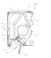
- FIG. 2 is a longitudinal section of the air conditioner indoor unit according to the embodiment of the present invention.
- FIG. 2 has shown the left side of the figure as the front side of an indoor unit.
- terms for indicating directions for example, “up”, “down”, “right”, “left”, etc.
- “upper”, “lower”, “right”, and “left” are used when the indoor unit main body 100 is viewed from the front.
- the indoor unit according to the present embodiment supplies conditioned air to an air-conditioning target area such as a room by using a refrigeration cycle that circulates refrigerant.
- an example is shown in which the indoor unit is a wall-mounted type that is attached to the wall surface of the air-conditioning target area.
- the indoor unit main body 100 includes a rear case 1 provided on the rear side and attached to a wall surface, a front panel 2 provided on the front side and formed with a recess 11 and a front inlet 12, and a front panel Design cover 3 attached to the front side of 2, an upper opening formed at the upper part, mainly an inlet port 4 for sucking indoor air into the interior, and an opening formed at the lower part to supply conditioned air to the air-conditioned area
- the blower outlet 5 is provided.
- the indoor unit main body 100 sucks room air from the upper suction port 4 and the front suction port 12 and blows conditioned air from the blower outlet 5, and covers the blower fan 6 from above. And a heat exchanger 7 that creates conditioned air by exchanging heat between the refrigerant and room air. And the air flow path is connected in the indoor unit main body 100 by these components. Further, in the indoor unit main body 100, an electrical component box (not shown) that accommodates a circuit board and the like, and a drain pan 8 that is provided below the lower end portion of the heat exchanger 7 and collects condensed water of the heat exchanger 7 are provided. And.
- the ventilation fan 6 is a crossflow fan, for example, and the heat exchanger 7 is a fin tube type heat exchanger, for example, it is not limited to them.
- a filter 9 is provided between the upper suction port 4 and the front suction port 12 and the heat exchanger 7 for removing dust contained in the sucked room air. Furthermore, the blower outlet 5 is provided with an up / down air direction adjusting plate 10 for controlling the blowing direction of the airflow.
- FIG. 3 is a perspective view showing the front panel 2 and the design cover 3 of the indoor unit of the air conditioner according to the embodiment of the present invention, and is a view before the design cover 3 is attached to the front panel 2
- FIG. 1 is a perspective view showing a front panel 2 and a design cover 3 of an indoor unit of an air conditioner according to an embodiment of the present invention, and is a view after the design cover 3 is attached to the front panel 2.
- FIG. 1 is a perspective view showing a front panel 2 and a design cover 3 of an indoor unit of an air conditioner according to an embodiment of the present invention, and is a view after the design cover 3 is attached to the front panel 2.
- the arrow in FIG. 3 has shown the position where the design cover 3 is attached.
- the front panel 2 has a flat surface shape in order to improve the design. Moreover, in the state which has rectangular shape and the indoor unit main body 100 was attached to the wall surface, a longitudinal direction turns into the left-right direction, ie, a horizontal direction, and a transversal direction turns into an up-down direction, ie, a vertical direction. Moreover, the recessed part 11 extended from the inner side of a left end part to the inner side of a right end part is formed in the center of an up-down direction seeing front. Therefore, as shown in FIG. 3, the front panel 2 has a center in the vertical direction that is recessed from the front side toward the back side, but the left and right front surfaces of the recess 11 are flat.
- the recessed part 11 is dented toward the back side from the front side, and the front inlet 12 is formed in the lower part of the recessed part 11. As shown in FIG. The position where the recess 11 is formed may not be strictly at the center in the vertical direction.
- FIG. 5 is a first side view schematically showing the design cover 3 of the indoor unit of the air conditioner according to the embodiment of the present invention
- FIG. 6 is an air conditioner according to the embodiment of the present invention
- Fig. 7 is a second side view schematically showing the design cover 3 of the indoor unit of Fig. 7.
- Fig. 7 is a front view schematically showing the design cover 3 of the indoor unit of the air conditioner according to the embodiment of the present invention.
- FIG. 8 is a longitudinal sectional view schematically showing the front panel 2 and the design cover 3 of the indoor unit of the air conditioner according to the embodiment of the present invention.
- the design cover 3 is made of a transparent part, and the entire front surface has a flat surface shape like the front panel 2. Moreover, in the state which has rectangular shape and the indoor unit main body 100 was attached to the wall surface, a longitudinal direction turns into the left-right direction, ie, a horizontal direction, and a transversal direction turns into an up-down direction, ie, a vertical direction. Further, as shown in FIG. 5, the design cover 3 includes a rectangular flat surface portion 3a and a peripheral wall portion 3b provided on each of the four side portions of the flat surface portion 3a and protruding to the back surface side.
- the design cover 3 is improved in design by being attached to the front side of the front panel 2 by a claw (not shown) provided on a part or all of the peripheral wall 3b.
- the method of attaching the design cover 3 to the front panel 2 is not limited to a nail, For example, you may attach using an adhesive agent.
- the design cover 3 is designed with a convex 20, a pearl paint 21, and a color paint 22 on the back side.
- a stimulus such as rubbing from the outside, and deterioration of the design surface can be suppressed.
- a plurality of protrusions 20 that continuously protrude from the left end portion to the right end portion of the flat surface portion 3a are provided.
- the protrusions 20 are provided with irregular widths and heights in the vertical direction.
- the interval between the adjacent protrusions 20 is also irregularly provided. That is, on the back side of the flat surface portion 3a of the design cover 3, hairline processing in which a plurality of minute protrusions 20 are provided in a single direction is performed.
- protrusions 20 As described above, it becomes easy to make a shadow on a part of the protrusions 20, and the protrusions 20 can be easily seen due to contrast with other light reflecting portions. In addition, it is possible to express a sophisticated and sophisticated design.
- a pearl paint 21 is applied to the back side of the design cover 3, that is, the back side of the flat surface part 3a and the inside of the peripheral wall part 3b.
- the color paint 22 is applied.
- the pearl paint 21 is a paint in which fine particles of stone mica are mixed, and when exposed to light, the fine particles become glossy. Therefore, pearl light is refracted and scattered by the projections 20 using the color of the color paint 22 as a background color. Due to the scattering of the light, the pearly color appears to stand out from any angle with respect to the design cover 3 which is a transparent part.
- the flat surface portion 3a is provided with the protrusion 20 on the back side and the pearl paint 21 and the color paint 22 are provided, but the peripheral wall portion 3b is not provided with the protrusion 20, and the pearl is formed on the inner side. Only the paint 21 and the color paint 22 are applied. Therefore, since the shadow is not formed like the flat surface portion 3a and it looks transparent and shiny, the flat surface portion 3a and the peripheral wall portion 3b have different appearances. And it becomes contrast and an accent and can improve design nature.
- the color paint 22 corresponds to the “background color paint” of the present invention.
- the design cover 3 is attached to the upper side and the lower side of the recess 11 with respect to the front side of the front panel 2.
- the design cover 3 attached to the upper side of the recess 11 of the front panel 2 is attached so as to cover from the upper end of the recess 11 to the upper end of the front panel 2 from the left end to the right end of the front panel 2.
- the design cover 3 attached to the lower side of the recess 11 of the front panel 2 is attached so as to cover from the lower end of the recess 11 to the lower end of the front panel 2 from the left end to the right end of the front panel 2.
- the design property when the indoor unit main body 100 is seen from the front is improved by attaching the design cover 3 to the front side of the front panel 2 in this way.
- the design cover 3 is attached to the upper side and the lower side of the concave portion 11 of the front panel 2 one by one.
- the present invention is not limited to this, and the design cover 3 is attached to the upper side of the concave portion 11 of the front panel 2.
- the design cover 3 may be divided into a plurality of parts such as two, and the design cover 3 attached to the lower side of the recess 11 of the front panel 2 may be divided into a plurality of parts such as two. May be.
- the indoor unit of the air conditioner since the design is given to the back side of the design cover 3, degradation of a design surface can be suppressed. Further, by providing a plurality of protrusions 20 that continuously protrude from the left end portion to the right end portion of the flat surface portion 3a on the back side of the flat surface portion 3a of the design cover 3, and arranging them in parallel in the vertical direction, The pearl paint 21 gets in well. Therefore, when the indoor unit of the air conditioner is looked up from below, the convexes 20 provided in the left-right direction are conspicuous, and the overall color tone is adjusted by the color paint 22 applied from above the pearl paint 21. can do.
- the back surface of the design cover 3 is provided with a plurality of protrusions 20 protruding continuously from the left end portion to the right end portion of the flat surface portion 3a.
- the flat surface portion 3a is provided instead of the protrusions 20, the flat surface portion 3a.
- a plurality of recesses that are continuously recessed from the left end portion to the right end portion may be provided, or both the protrusions 20 and the recesses may be provided.
Landscapes
- Engineering & Computer Science (AREA)
- Chemical & Material Sciences (AREA)
- Combustion & Propulsion (AREA)
- Mechanical Engineering (AREA)
- General Engineering & Computer Science (AREA)
- Air Filters, Heat-Exchange Apparatuses, And Housings Of Air-Conditioning Units (AREA)
Abstract
Description
以上のように、特許文献1および特許文献2では、透明な前面パネルの背面側に塗装などでデザインを施すことにより、外部から擦れなどの刺激を受けづらくし、意匠面の劣化を抑制しつつ意匠性を向上させている。
図1は、本発明の実施の形態に係る空気調和機の室内機を正面側から見た外観斜視図であり、図2は、本発明の実施の形態に係る空気調和機の室内機の縦断面図である。
なお、図2は、図の左側を室内機の前面側として示している。
また、以下の説明において、理解を容易にするために方向を表す用語(例えば「上」、「下」、「右」、「左」など)を適宜用いるが、これは説明のためのものであって、これらの用語は本願発明を限定するものではない。また、本実施の形態では、室内機本体100を正面視した状態において、「上」、「下」、「右」、「左」を使用する。
本実施の形態に係る室内機は、冷媒を循環させる冷凍サイクルを利用することで室内などの空調対象域に空調空気を供給するものである。なお、本実施の形態では、室内機が空調対象域の壁面に取り付けられる壁掛け型である場合を例に示している。
まず、室内空気は、送風ファン6によって室内機本体100の上部吸込口4および前面吸込口12から室内機本体100内に流れ込む。このとき、フィルター9によって空気に含まれている塵埃などが除去される。この室内空気は、熱交換器7を通過する際に熱交換器7内を導通している冷媒によって加熱または冷却されて空調空気となる。そして、空調空気は、上下風向調整板10によって風向きが調整され、吹出口5から室内機本体100の外部、つまり空調対象域に吹き出されるようになっている。
なお、凹部11が形成されている位置は、厳密に上下方向の中央でなくてもよい。
なお、周壁部3bは、平面部3aの四側部全てにではなく、四側部のうち一部に設けてもよい。また、意匠カバー3を前面パネル2に取り付ける方法は爪に限定されず、例えば、接着剤などを用いて取り付けてもよい。
パール塗料21は、石の雲母の微粒子が混合された塗料で、光が当たるとその微粒子により光沢が出る。そのため、カラー塗料22の色を背景色として、パール色の光が凸20により屈折して散乱する。その光の散乱により、透明部品である意匠カバー3に対していずれの角度から見てもパール色の輝きが際立って見える。
Claims (3)
- 室内機本体の前面側に設けられる前面パネルと、
透明部品からなり、前記前面パネルの前面側から覆うように取り付けられる意匠カバーと、を備えた壁掛け用の空気調和機の室内機であって、
前記意匠カバーは、
矩形状の平面部と、該平面部の側部に設けられ、背面側に突出した周壁部と、を有し、
前記平面部は、
正面視して背面側に左端部から右端部にかけて、連続して突出した凸、または連続して凹んだ凹が複数設けられ、該凸または該凹は上下方向に並設されており、
前記意匠カバーの背面側には、パール塗料の塗装が施されており、さらに前記パール塗料の上から背景色塗料の塗装が施されている
空気調和機の室内機。 - 前記前面パネルおよび前記意匠カバーは、前面の全体がフラットである
請求項1に記載の空気調和機の室内機。 - 前記意匠カバーは無色透明であり、
前記背景色塗料は白色である
請求項1または2に記載の空気調和機の室内機。
Priority Applications (7)
| Application Number | Priority Date | Filing Date | Title |
|---|---|---|---|
| JP2017536094A JPWO2017033257A1 (ja) | 2015-08-24 | 2015-08-24 | 空気調和機の室内機 |
| EP15902228.4A EP3343124A4 (en) | 2015-08-24 | 2015-08-24 | INDOOR UNIT OF AN AIR-CONDITIONING SYSTEM |
| RU2018102805A RU2676638C1 (ru) | 2015-08-24 | 2015-08-24 | Комнатный блок устройства для кондиционирования воздуха |
| US15/735,351 US20180172312A1 (en) | 2015-08-24 | 2015-08-24 | Air-conditioning apparatus indoor unit |
| AU2015407137A AU2015407137B2 (en) | 2015-08-24 | 2015-08-24 | Air-conditioning apparatus indoor unit |
| CN201580082107.8A CN107923649A (zh) | 2015-08-24 | 2015-08-24 | 空调机的室内机 |
| PCT/JP2015/073703 WO2017033257A1 (ja) | 2015-08-24 | 2015-08-24 | 空気調和機の室内機 |
Applications Claiming Priority (1)
| Application Number | Priority Date | Filing Date | Title |
|---|---|---|---|
| PCT/JP2015/073703 WO2017033257A1 (ja) | 2015-08-24 | 2015-08-24 | 空気調和機の室内機 |
Publications (1)
| Publication Number | Publication Date |
|---|---|
| WO2017033257A1 true WO2017033257A1 (ja) | 2017-03-02 |
Family
ID=58100067
Family Applications (1)
| Application Number | Title | Priority Date | Filing Date |
|---|---|---|---|
| PCT/JP2015/073703 Ceased WO2017033257A1 (ja) | 2015-08-24 | 2015-08-24 | 空気調和機の室内機 |
Country Status (7)
| Country | Link |
|---|---|
| US (1) | US20180172312A1 (ja) |
| EP (1) | EP3343124A4 (ja) |
| JP (1) | JPWO2017033257A1 (ja) |
| CN (1) | CN107923649A (ja) |
| AU (1) | AU2015407137B2 (ja) |
| RU (1) | RU2676638C1 (ja) |
| WO (1) | WO2017033257A1 (ja) |
Cited By (4)
| Publication number | Priority date | Publication date | Assignee | Title |
|---|---|---|---|---|
| JP2022085728A (ja) * | 2020-11-27 | 2022-06-08 | 株式会社富士通ゼネラル | 樹脂部材 |
| JP2022089682A (ja) * | 2020-12-04 | 2022-06-16 | 株式会社富士通ゼネラル | 樹脂部材及び空気調和機の室内機 |
| JP2022089681A (ja) * | 2020-12-04 | 2022-06-16 | 株式会社富士通ゼネラル | 樹脂部材及び空気調和機の室内機 |
| EP4325135A4 (en) * | 2021-04-16 | 2024-05-01 | Mitsubishi Electric Corporation | AIR CONDITIONING DEVICE AND AIR CONDITIONING SYSTEM |
Families Citing this family (1)
| Publication number | Priority date | Publication date | Assignee | Title |
|---|---|---|---|---|
| USD1004756S1 (en) * | 2020-12-24 | 2023-11-14 | Lg Electronics Inc. | Modular air conditioner |
Citations (3)
| Publication number | Priority date | Publication date | Assignee | Title |
|---|---|---|---|---|
| JP2006234335A (ja) * | 2005-02-28 | 2006-09-07 | Daikin Ind Ltd | 空気処理装置 |
| JP2013100939A (ja) * | 2011-11-09 | 2013-05-23 | Fujitsu General Ltd | 空気調和機の室内機 |
| JP5264860B2 (ja) * | 2010-10-27 | 2013-08-14 | 三菱電機株式会社 | 空気調和機 |
Family Cites Families (12)
| Publication number | Priority date | Publication date | Assignee | Title |
|---|---|---|---|---|
| US5044260A (en) * | 1990-06-21 | 1991-09-03 | Cts Consolidated Technical Services, Inc. | Air distribution unit |
| JP2992066B2 (ja) * | 1990-09-14 | 1999-12-20 | 大日本印刷株式会社 | 化粧材、化粧材の製造方法及び化粧材の製造に使用するエンボス版 |
| JPH081770A (ja) * | 1994-06-21 | 1996-01-09 | Dainippon Printing Co Ltd | エンボス版及びその製造方法 |
| IL123390A (en) * | 1997-04-03 | 2000-11-21 | Funai Electric Co | Air conditioning system |
| JP4237878B2 (ja) * | 1999-06-29 | 2009-03-11 | 大日本印刷株式会社 | 万線状凹凸模様を有する化粧材、及びその製造方法 |
| JP4045147B2 (ja) * | 2002-08-26 | 2008-02-13 | 日立アプライアンス株式会社 | 空気調和機 |
| JP3641721B2 (ja) * | 2003-08-29 | 2005-04-27 | ダイキン工業株式会社 | 空気調和機の室内機および空気調和機の室内機の製造方法 |
| JP3642064B2 (ja) * | 2003-09-01 | 2005-04-27 | ダイキン工業株式会社 | 空気調和機の室内機およびその製造方法 |
| US8097073B2 (en) * | 2005-11-01 | 2012-01-17 | Lg Electronics Inc. | Dehumidifier |
| US8158885B2 (en) * | 2007-07-13 | 2012-04-17 | Susan Eastin | Paintable wall plate covering and method |
| JP5564413B2 (ja) * | 2010-12-13 | 2014-07-30 | シチズンホールディングス株式会社 | 時計用表示板 |
| CN203797902U (zh) * | 2013-12-24 | 2014-08-27 | 珠海格力电器股份有限公司 | 空调器面板和空调器 |
-
2015
- 2015-08-24 AU AU2015407137A patent/AU2015407137B2/en not_active Ceased
- 2015-08-24 US US15/735,351 patent/US20180172312A1/en not_active Abandoned
- 2015-08-24 CN CN201580082107.8A patent/CN107923649A/zh active Pending
- 2015-08-24 JP JP2017536094A patent/JPWO2017033257A1/ja active Pending
- 2015-08-24 RU RU2018102805A patent/RU2676638C1/ru active
- 2015-08-24 EP EP15902228.4A patent/EP3343124A4/en active Pending
- 2015-08-24 WO PCT/JP2015/073703 patent/WO2017033257A1/ja not_active Ceased
Patent Citations (3)
| Publication number | Priority date | Publication date | Assignee | Title |
|---|---|---|---|---|
| JP2006234335A (ja) * | 2005-02-28 | 2006-09-07 | Daikin Ind Ltd | 空気処理装置 |
| JP5264860B2 (ja) * | 2010-10-27 | 2013-08-14 | 三菱電機株式会社 | 空気調和機 |
| JP2013100939A (ja) * | 2011-11-09 | 2013-05-23 | Fujitsu General Ltd | 空気調和機の室内機 |
Non-Patent Citations (1)
| Title |
|---|
| See also references of EP3343124A4 * |
Cited By (4)
| Publication number | Priority date | Publication date | Assignee | Title |
|---|---|---|---|---|
| JP2022085728A (ja) * | 2020-11-27 | 2022-06-08 | 株式会社富士通ゼネラル | 樹脂部材 |
| JP2022089682A (ja) * | 2020-12-04 | 2022-06-16 | 株式会社富士通ゼネラル | 樹脂部材及び空気調和機の室内機 |
| JP2022089681A (ja) * | 2020-12-04 | 2022-06-16 | 株式会社富士通ゼネラル | 樹脂部材及び空気調和機の室内機 |
| EP4325135A4 (en) * | 2021-04-16 | 2024-05-01 | Mitsubishi Electric Corporation | AIR CONDITIONING DEVICE AND AIR CONDITIONING SYSTEM |
Also Published As
| Publication number | Publication date |
|---|---|
| AU2015407137B2 (en) | 2019-03-07 |
| AU2015407137A1 (en) | 2018-03-29 |
| EP3343124A1 (en) | 2018-07-04 |
| JPWO2017033257A1 (ja) | 2018-03-22 |
| EP3343124A4 (en) | 2019-04-24 |
| RU2676638C1 (ru) | 2019-01-09 |
| US20180172312A1 (en) | 2018-06-21 |
| CN107923649A (zh) | 2018-04-17 |
Similar Documents
| Publication | Publication Date | Title |
|---|---|---|
| WO2017033257A1 (ja) | 空気調和機の室内機 | |
| US20160290662A1 (en) | Ceiling-embedded air conditioner | |
| US20160290661A1 (en) | Ceiling-embedded air conditioner | |
| CN105829808A (zh) | 空调 | |
| JP6207479B2 (ja) | 空気調和機の室内機、及び、空気調和機の室内機の製造方法 | |
| JP6398550B2 (ja) | 天井埋込型空気調和機 | |
| JP6479214B2 (ja) | 空気調和機の室内機 | |
| JP6641392B2 (ja) | 空気調和装置の室内機 | |
| JP6575599B2 (ja) | 空気調和機の室内機 | |
| JP6451516B2 (ja) | 天井埋込型空気調和機 | |
| AU2016420909B2 (en) | Heat exchanger unit and air-conditioning apparatus | |
| JP5880163B2 (ja) | 天井埋込型空気調和機 | |
| JP6384244B2 (ja) | 天井埋込型空気調和機 | |
| JP5264860B2 (ja) | 空気調和機 | |
| JP7590877B2 (ja) | 室内機及び室内機用鏡 | |
| CN205402850U (zh) | 油烟机 | |
| JP6418122B2 (ja) | 室内機 | |
| WO2015189993A1 (ja) | 空気調和機 | |
| WO2017022072A1 (ja) | 空調用室内機 | |
| JP2018173214A (ja) | 空気調和装置の室内機 |
Legal Events
| Date | Code | Title | Description |
|---|---|---|---|
| 121 | Ep: the epo has been informed by wipo that ep was designated in this application |
Ref document number: 15902228 Country of ref document: EP Kind code of ref document: A1 |
|
| ENP | Entry into the national phase |
Ref document number: 2017536094 Country of ref document: JP Kind code of ref document: A |
|
| WWE | Wipo information: entry into national phase |
Ref document number: 15735351 Country of ref document: US |
|
| NENP | Non-entry into the national phase |
Ref country code: DE |
|
| ENP | Entry into the national phase |
Ref document number: 2015407137 Country of ref document: AU Date of ref document: 20150824 Kind code of ref document: A |