WO2017038237A1 - 保管装置および保管方法 - Google Patents
保管装置および保管方法 Download PDFInfo
- Publication number
- WO2017038237A1 WO2017038237A1 PCT/JP2016/069770 JP2016069770W WO2017038237A1 WO 2017038237 A1 WO2017038237 A1 WO 2017038237A1 JP 2016069770 W JP2016069770 W JP 2016069770W WO 2017038237 A1 WO2017038237 A1 WO 2017038237A1
- Authority
- WO
- WIPO (PCT)
- Prior art keywords
- container
- purge
- storage
- storage shelf
- command
- Prior art date
- Legal status (The legal status is an assumption and is not a legal conclusion. Google has not performed a legal analysis and makes no representation as to the accuracy of the status listed.)
- Ceased
Links
Images

Classifications
-
- B—PERFORMING OPERATIONS; TRANSPORTING
- B65—CONVEYING; PACKING; STORING; HANDLING THIN OR FILAMENTARY MATERIAL
- B65G—TRANSPORT OR STORAGE DEVICES, e.g. CONVEYORS FOR LOADING OR TIPPING, SHOP CONVEYOR SYSTEMS OR PNEUMATIC TUBE CONVEYORS
- B65G1/00—Storing articles, individually or in orderly arrangement, in warehouses or magazines
- B65G1/02—Storage devices
- B65G1/14—Stack holders or separators
-
- H—ELECTRICITY
- H10—SEMICONDUCTOR DEVICES; ELECTRIC SOLID-STATE DEVICES NOT OTHERWISE PROVIDED FOR
- H10P—GENERIC PROCESSES OR APPARATUS FOR THE MANUFACTURE OR TREATMENT OF DEVICES COVERED BY CLASS H10
- H10P72/00—Handling or holding of wafers, substrates or devices during manufacture or treatment thereof
- H10P72/04—Apparatus for manufacture or treatment
- H10P72/0402—Apparatus for fluid treatment
-
- H—ELECTRICITY
- H10—SEMICONDUCTOR DEVICES; ELECTRIC SOLID-STATE DEVICES NOT OTHERWISE PROVIDED FOR
- H10P—GENERIC PROCESSES OR APPARATUS FOR THE MANUFACTURE OR TREATMENT OF DEVICES COVERED BY CLASS H10
- H10P72/00—Handling or holding of wafers, substrates or devices during manufacture or treatment thereof
- H10P72/10—Handling or holding of wafers, substrates or devices during manufacture or treatment thereof using carriers specially adapted therefor, e.g. front opening unified pods [FOUP]
- H10P72/18—Handling or holding of wafers, substrates or devices during manufacture or treatment thereof using carriers specially adapted therefor, e.g. front opening unified pods [FOUP] characterised by being specially adapted for supporting a single substrate or by comprising a stack of such individual supports
-
- H—ELECTRICITY
- H10—SEMICONDUCTOR DEVICES; ELECTRIC SOLID-STATE DEVICES NOT OTHERWISE PROVIDED FOR
- H10P—GENERIC PROCESSES OR APPARATUS FOR THE MANUFACTURE OR TREATMENT OF DEVICES COVERED BY CLASS H10
- H10P72/00—Handling or holding of wafers, substrates or devices during manufacture or treatment thereof
- H10P72/10—Handling or holding of wafers, substrates or devices during manufacture or treatment thereof using carriers specially adapted therefor, e.g. front opening unified pods [FOUP]
- H10P72/19—Handling or holding of wafers, substrates or devices during manufacture or treatment thereof using carriers specially adapted therefor, e.g. front opening unified pods [FOUP] closed carriers
- H10P72/1924—Handling or holding of wafers, substrates or devices during manufacture or treatment thereof using carriers specially adapted therefor, e.g. front opening unified pods [FOUP] closed carriers characterised by atmosphere control
-
- H—ELECTRICITY
- H10—SEMICONDUCTOR DEVICES; ELECTRIC SOLID-STATE DEVICES NOT OTHERWISE PROVIDED FOR
- H10P—GENERIC PROCESSES OR APPARATUS FOR THE MANUFACTURE OR TREATMENT OF DEVICES COVERED BY CLASS H10
- H10P72/00—Handling or holding of wafers, substrates or devices during manufacture or treatment thereof
- H10P72/30—Handling or holding of wafers, substrates or devices during manufacture or treatment thereof for conveying, e.g. between different workstations
- H10P72/32—Handling or holding of wafers, substrates or devices during manufacture or treatment thereof for conveying, e.g. between different workstations between different workstations
- H10P72/3218—Conveying cassettes, containers or carriers
-
- H—ELECTRICITY
- H10—SEMICONDUCTOR DEVICES; ELECTRIC SOLID-STATE DEVICES NOT OTHERWISE PROVIDED FOR
- H10P—GENERIC PROCESSES OR APPARATUS FOR THE MANUFACTURE OR TREATMENT OF DEVICES COVERED BY CLASS H10
- H10P72/00—Handling or holding of wafers, substrates or devices during manufacture or treatment thereof
- H10P72/30—Handling or holding of wafers, substrates or devices during manufacture or treatment thereof for conveying, e.g. between different workstations
- H10P72/34—Handling or holding of wafers, substrates or devices during manufacture or treatment thereof for conveying, e.g. between different workstations the wafers being stored in a carrier, involving loading and unloading
- H10P72/3404—Storage means
-
- H—ELECTRICITY
- H10—SEMICONDUCTOR DEVICES; ELECTRIC SOLID-STATE DEVICES NOT OTHERWISE PROVIDED FOR
- H10P—GENERIC PROCESSES OR APPARATUS FOR THE MANUFACTURE OR TREATMENT OF DEVICES COVERED BY CLASS H10
- H10P72/00—Handling or holding of wafers, substrates or devices during manufacture or treatment thereof
- H10P72/30—Handling or holding of wafers, substrates or devices during manufacture or treatment thereof for conveying, e.g. between different workstations
- H10P72/36—Handling or holding of wafers, substrates or devices during manufacture or treatment thereof for conveying, e.g. between different workstations using air tracks
-
- H—ELECTRICITY
- H10—SEMICONDUCTOR DEVICES; ELECTRIC SOLID-STATE DEVICES NOT OTHERWISE PROVIDED FOR
- H10P—GENERIC PROCESSES OR APPARATUS FOR THE MANUFACTURE OR TREATMENT OF DEVICES COVERED BY CLASS H10
- H10P72/00—Handling or holding of wafers, substrates or devices during manufacture or treatment thereof
- H10P72/30—Handling or holding of wafers, substrates or devices during manufacture or treatment thereof for conveying, e.g. between different workstations
- H10P72/37—Handling or holding of wafers, substrates or devices during manufacture or treatment thereof for conveying, e.g. between different workstations with orientating and positioning by means of a vibratory bowl or track
Definitions
- the present invention relates to a storage device and a storage method.
- devices such as silicon wafers and glass wafers are subjected to various processes such as thin film formation, oxidation, and etching to manufacture devices.
- processes such as thin film formation, oxidation, and etching to manufacture devices.
- an article such as a substrate or a reticle used for the process is accommodated in a container, and the container is transported by a transport device.
- a storage device buffer, stocker
- for temporarily storing the container is provided at a delivery place between the transfer device and the processing device (see, for example, Patent Document 1 below).
- Temporarily storing the container that is next carried out by the transport device and / or the container for the article that is next processed by the processing device in the storage device can reduce the waiting time of the transport device and the processing device.
- the conveyance efficiency and the processing efficiency can be increased.
- a storage device for example, a storage warehouse.
- a purge device is provided in a storage shelf for storing the container, and the purge process is performed by the purge device each time the container is placed on the storage shelf.
- the container carried into the processing apparatus or the container carried out from the processing apparatus does not need to be purged by the storage apparatus.
- a purging process may be required for a container that stores an article before processing by the processing apparatus, but a purging process may not be necessary for a container that stores an article after processing by the processing apparatus.
- a purge process is not required for a container that stores an article before processing by the processing apparatus, but a purge process may be necessary for a container that stores an article after processing by the processing apparatus. In such a case, if the purge process is performed both at the time of carry-in and at the time of carry-out, the cost and time required for the purge process are wasted.
- the present invention has been made in view of the above-described circumstances, and an object thereof is to provide a storage device and a storage method capable of omitting an unnecessary purge process while maintaining a good environment in a container.
- the storage device of the present invention includes a storage shelf that stores containers, a purge device that is provided in the storage shelf and can perform a purging process on the containers, a container carry-in source to the storage shelf, and a container from the storage shelf And a purge determining unit that determines at least one of necessity and conditions of the purge process according to at least one of the unloading destinations.
- the purge determining unit determines whether or not purge processing is necessary according to a conveyance command to the loading / unloading device. But you can.
- a container that is provided between the processing device for processing the articles contained in the container and is transferred between the transport vehicle port to which the container is transferred by the transport vehicle and the load port of the processing device is stored in a storage shelf.
- the purge determining unit determines whether or not purge processing is necessary based on a transport command between the transport vehicle port and the storage shelf for the loading / unloading device or a transport command between the load port and the storage shelf for the loading / unloading device. It may be determined.
- the purge determining unit may specify that the carry-in source is the transport vehicle port. Further, when the transport command is a command for transporting the container from the transport vehicle port to the storage shelf, the purge determining unit may specify that the carry-out destination is the load port. Further, when the transport command is a command for transporting the container from the load port to the storage shelf, the purge determining unit may specify that the carry-in source is the load port. Further, when the transport command is a command for transporting the container from the load port to the storage shelf, the purge determining unit may specify that the carry-out destination is the transport vehicle port.
- the purge determination unit may determine whether the purge process is necessary by comparing the result of specifying the carry-out destination with information that associates the carry-out destination with the necessity of the purge process. In addition, the purge determination unit may determine whether or not the purge process is necessary by comparing the result of specifying the carry-in source with information that associates the carry-in source and the necessity of the purge process.
- the storage method of the present invention includes storing a container on a storage shelf, purging the container with a purge device provided on the storage shelf, bringing the container into the storage shelf, and removing the container from the storage shelf. Determining at least one of necessity and condition of purge processing according to at least one of the destinations.
- the necessity of the purge process is determined according to at least one of the container carry-in source to the storage shelf and the container carry-out destination from the storage shelf, so that the environment in the container is kept good. Unnecessary purge processing can be omitted.
- a storage device that includes a loading / unloading device that carries containers into and out of the storage shelf, and the purge determination unit determines whether or not purge processing is necessary according to a conveyance command to the loading / unloading device. In the apparatus, since the transfer command used for the operation of the loading / unloading apparatus is used, it is possible to easily and reliably determine whether or not the purge process is necessary.
- a container that is provided between the processing device for processing the articles contained in the container and is transferred between the transport vehicle port to which the container is transferred by the transport vehicle and the load port of the processing device is stored in a storage shelf.
- the purge determining unit determines whether or not purge processing is necessary based on a transport command between the transport vehicle port and the storage shelf for the loading / unloading device or a transport command between the load port and the storage shelf for the loading / unloading device. Since the storage device to be determined is based on the transport command between the transport vehicle port or the load port and the storage shelf, the carry-in source and the transport-out destination can be reliably identified, and the necessity of the purge process can be determined easily and reliably. be able to.
- the purge determining unit reliably specifies the transport source in the storage device that identifies the transport source as the transport vehicle port. can do. Further, when the transport command is a command for transporting the container from the transport vehicle port to the storage shelf, the purge determining unit must reliably specify the transport destination in the storage device that specifies that the transport destination is the load port. Can do. Further, when the transport command is a command for transporting the container from the load port to the storage shelf, the purge determining unit can reliably identify the carry-in source in the storage device that identifies the carry-in source as the load port. .
- the purge determining unit reliably identifies the transport destination in the storage device that identifies the transport destination as the transport vehicle port. Can do. Further, the purge determining unit collates the result of specifying the carry-out destination with reference information that associates the carry-out destination with the necessity of the purge process, and the storage device that determines the necessity of the purge process requires No can be determined easily and reliably.
- the purge determining unit collates the result of specifying the carry-in source with reference information that associates the carry-in source with the necessity of the purge process, and in the storage device that determines the necessity of the purge process, the purge determination unit No can be easily and reliably determined.
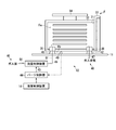
- FIG. 1 is a diagram illustrating an example of a manufacturing system SYS to which the storage device 1 according to the embodiment is applied.
- the manufacturing system SYS manufactures various devices such as semiconductor devices and liquid crystal devices.
- the manufacturing system SYS manufactures semiconductor devices by forming structures such as semiconductor elements, wirings, and insulating films on a substrate such as a silicon wafer.
- the manufacturing system SYS includes a storage device 1, a processing device 2, and a transport vehicle (ceiling transport vehicle 3).
- the processing apparatus 2 executes a process of a device manufacturing process.
- the processing apparatus 2 is, for example, a film forming apparatus, a coater / developer, an exposure apparatus, an etching apparatus, or the like.
- a container F containing articles related to processing is carried into and out of the processing apparatus 2 via load ports 4 and 5.
- the article related to processing is, for example, a substrate to be processed or an article (eg, reticle) used for processing.
- the processing apparatus 2 receives the container F at the load port 4, takes out the substrate accommodated in the container F, and performs a predetermined process on the substrate. Further, the processing apparatus 2 accommodates the processed substrate again in the container F and passes it to the load port 5.
- the ceiling transport vehicle 3 is an OHT vehicle, for example, and is movable along a rail (not shown) installed on the ceiling (not shown) of the facility.
- the overhead conveyance vehicle 3 conveys the container F outside the storage device 1 by moving the container F while holding (for example, holding) the container F.
- the ceiling transport vehicle 3 transports a container F that contains an article related to processing of the processing device 2.
- the ceiling conveyance vehicle 3 receives the container F which accommodated the articles
- the overhead conveyance vehicle 3 delivers the container F at the conveyance vehicle ports (entry / exit ports 6 and 7).
- the ceiling transport vehicle 3 passes the container F carried into the processing device 2 through the loading / unloading port 6 (warehousing port) and receives the container F carried out from the processing device 2 through the loading / unloading port 7 (shipping port).
- the storage device 1 is a tool buffer or the like, and is attached to the processing device 2.
- the storage device 1 is disposed on a transport path between the ceiling transport vehicle 3 and the processing device 2.
- the storage device 1 stores the container F delivered between the loading / unloading ports 6 and 7 through which the container F is delivered by the ceiling transport vehicle 3 and the load ports 4 and 5 of the processing device 2.
- the storage device 1 receives the container F when the ceiling transport vehicle 3 transports the container F to the loading / unloading port 6 and temporarily stores the container F until it is passed to the processing device 2. As a result, the next container F can be received at the loading / unloading port 6.
- the storage device 1 temporarily stores the container F carried out from the processing device 2 and passes it to the loading / unloading port 7 when the loading / unloading port 7 is empty. Thereby, in the loading / unloading port 7, the ceiling conveyance vehicle 3 can receive the container F. As described above, by temporarily storing the container F in the storage device 1, the waiting time of the ceiling transport vehicle 3 can be reduced, and the transport efficiency is increased. In addition, the storage device 1 temporarily stores the container F received from the ceiling transport vehicle 3 and then passes the container F to the load port 4 when the load port 4 of the processing device 2 is empty. Thereby, the processing apparatus 2 can receive the next container F promptly after completion
- the storage apparatus 1 receives the container F and temporarily stores it. As a result, the processing apparatus 2 can pass the next container F to the load port 5.
- the standby time of the processing device 2 can be reduced, and the processing efficiency is increased.
- the storage device 1 includes a storage shelf 11, a purge device 12 (also shown in FIG. 2 later) provided in the storage shelf 11, a loading / unloading device (transfer device 13), and a storage control device 14.
- the storage control device 14 comprehensively controls each part of the storage device 1.
- the storage control device 14 is provided with a purge determination unit 15 and a storage unit 16.
- the storage shelves 11 are arranged one or more in the height direction (Z direction), and a plurality of storage shelves 11 are arranged in the horizontal direction (X direction). Each of the plurality of storage shelves 11 is supported by the frame 21 of the storage device 1.
- a container F can be placed on each of the plurality of storage shelves 11.
- the plurality of storage shelves 11 are shelves that can hold the containers F purged by the purge device 12.
- the storage device 1 has a structure in which load ports 4 and 5, storage shelves 11 and storage ports 6 and 7 are arranged in multiple stages in the Z direction, load ports 4 and 5 are arranged in the lower stage, and storage shelves 11 in the middle stage. Is placed, and the loading / unloading ports 6 and 7 are arranged on the upper stage.
- the number and arrangement of the storage shelves 11 are not limited, and the number and arrangement of the storage shelves 11 are arbitrarily set.
- the transfer device 13 transports the container F inside the storage device 1 (for example, a space surrounded by the frame 21).
- the transfer device 13 can transport the container F between the loading / unloading ports 6 and 7 and the storage shelf 11, and can transport the container F between the load ports 4 and 5 and the storage shelf 11. is there.
- the transfer device 13 carries the container F passed to the loading / unloading port 6 into the storage shelf 11, unloads the container F from the storage shelf 11, and passes it to the load port 4.
- the carry-in source of the container F to the storage shelf 11 is the loading / unloading port 6, and the carry-out destination of the container F from the storage shelf 11 is the load port 4.
- the transfer device 13 can carry the container F delivered to the load port 5 into the storage shelf 11, carry out the container F from the storage shelf 11, and deliver it to the loading / unloading port 7.
- the loading source of the container F to the storage shelf 11 is the load port 5
- the shipping destination of the container F from the storage shelf 11 is the loading / unloading port 7.
- the transfer device 13 includes a horizontal guide 22, a horizontal slider 23, a vertical guide 24, a vertical slider 25, an arm 26, and a transfer control unit 27.
- the horizontal guide 22 is attached to the frame 21 and extends in the X direction.
- the horizontal slider 23 is movable in the X direction along the horizontal guide 22.
- the vertical guide 24 is attached to the horizontal slider 23 and extends in the Z direction.
- the vertical guide 24 moves in the X direction together with the horizontal slider 23 when the horizontal slider 23 moves.
- the vertical slider 25 is movable in the Z direction along the vertical guide 24.
- the arm 26 is attached to the vertical slider 25.
- the arm 26 moves in the X direction together with the horizontal slider 23 and the vertical slider 25 when the horizontal slider 23 moves.
- the arm 26 moves in the Z direction together with the vertical slider 25 when the vertical slider 25 moves.
- the arm 26 is a robot arm having one or two or more joints, and a distal end side thereof is a U-shaped gripping portion 26a.
- the arm 26 can move the gripping portion 26a in the X direction and the Y direction, for example, by expansion and contraction of a joint.
- the gripping portion 26 a is inserted under the flange portion 34 (also shown in FIG. 2 later) of the container F and grips the container F.
- the arm 26 can move the container F in the X direction and the Y direction by extending and contracting the joint while the container F is gripped by the gripping portion 26a.
- the container F may be moved in the X direction by moving the horizontal slider 23.
- the transfer device 13 can move the container F in the X direction and the Z direction by the movement of the horizontal slider 23 and the movement of the vertical slider 25 while the container F is gripped by the gripping portion 26a.
- the transfer control unit 27 controls the driving unit of the horizontal slider 23, the driving unit of the vertical slider 25, and the driving unit of the arm 26, respectively. In FIG. 3 later, these driving units are denoted by reference numeral 28.
- the transfer control unit 27 is connected to the storage control device 14 so as to be communicable, and controls the drive unit according to a transport command supplied from the storage control device 14.
- the transport command is a command for requesting transport of the container F by designating a starting point and an end point of transporting the container F.
- the transfer apparatus 13 is not limited to said structure, For example, the bottom of the container F may be scooped up, the container F may be hold
- FIG. 2 is a diagram showing the purge device 12.
- the container F may be a SMIF Pod, a reticle Pod, or the like.
- the container F includes a box-shaped main body portion 32 having an opening 31 on the front surface and a lid portion 33 that closes the opening 31. Articles such as wafers are accommodated in the interior Fa (internal space, accommodation space) of the container F through the opening 31.
- a flange portion 34 is provided on the upper portion of the main body portion 32.
- the main body 32 includes a positioning recess (not shown) on the bottom surface Fb side. Positioning pins (not shown) are provided on the upper surface of the storage shelf 11.
- the main body portion 32 of the container F includes a gas introduction port 35 and a gas exhaust port 36 on the bottom surface Fb side.
- the gas introduction port 35 is provided with, for example, a gas introduction port, a filter, and a check valve.
- the gas inlet communicates with the inside Fa and the outside of the main body 32.
- the inside of the gas inlet is a flow path of the purge gas G1 supplied to the internal Fa of the container F, and the filter is provided in this flow path.
- the filter is a particle filter, for example, and removes dust contained in the gas passing through the gas inlet.
- the check valve of the gas introduction port 35 prevents the gas from flowing out from the inside Fa of the container F to the outside through the gas introduction port.
- the gas exhaust port 36 is provided with an exhaust port, a check valve, and a filter. The exhaust port communicates with the inside Fa and the outside of the main body 32.
- the check valve of the gas exhaust port 36 prevents the gas from flowing from the outside of the container F into the internal Fa through the exhaust port.
- the filter is a particle filter, for example, and removes dust contained in the gas passing through the exhaust port.
- the ratio of the atmospheric gas in the internal Fa in the container F before the purge process is high immediately after the start of the purge process, and the ratio of the purge gas G1 increases as time elapses from the start of the purge process.
- the purge device 12 is provided in the storage shelf 11 and can purge the container F.
- the purge device 12 includes a purge nozzle 41, an exhaust nozzle 42, a flow rate control device 43, and a purge control unit 44.
- the purge nozzle 41 and the exhaust nozzle 42 are provided on the upper surface of the storage shelf 11.
- the purge nozzle 41 and the exhaust nozzle 42 are arranged so as to be connected to the gas introduction port and the exhaust port, respectively, when the container F is placed on the storage shelf 11.
- the gas inlet of the container F is connected to the pipe 45 via the purge nozzle 41 and further connected to the gas source 46 via the flow rate control device 43.
- the exhaust nozzle 42 is connected to an exhaust path (gas exhaust 48) of the purge gas G1 through a pipe 47.
- the gas source 46 supplies the purge gas G1.
- the type of the purge gas G1 is selected according to the contents (article) accommodated in the container F. For example, a gas that suppresses oxidation of the contained material, suppresses molecular contamination, a gas that reduces the moisture in the container F, or the like is used.
- a gas inert to the accommodation such as nitrogen gas is used as the purge gas G1.
- a dry gas such as clean dry air (CDA) is used as the purge gas G1.
- CDA clean dry air
- the gas source 46 may be a part of the storage device 1 or may be an external device of the storage device 1, for example, a part of equipment in which the storage device 1 is provided.
- the purge gas G1 from the gas source 46 is supplied to the internal Fa from the gas inlet of the container F via the flow rate control device 43 and the pipe 45, and is filled into the internal Fa of the container F. . Further, the gas in the internal Fa is discharged from the exhaust port to the outside of the container F, and is exhausted to the outside by the gas exhaust 48 through the pipe 45.
- the gas exhaust 48 may be provided with a device for sucking gas by a pump or the like. Further, the container F may not include the gas exhaust port 36, and in this case, the purge device 12 may not include the exhaust nozzle 42.
- the gas in the internal Fa of the container F leaks to the outside through the gap between the opening 31 and the lid 33, so The gas of the internal Fa can be exhausted to the outside.
- the flow rate control device 43 controls the flow rate of the purge gas G1 in the pipe 45 (the flow path between the gas inlet of the vessel F and the gas source 46) connected to the vessel F.
- the flow control device 43 is a mass flow controller, for example, and has a flow path through which the purge gas G1 flows.
- the flow path inside the flow control device 43 is provided with a flow control valve such as a flow meter or a solenoid valve using a self-heating resistor.
- the flow control device 43 feedback-controls the solenoid valve based on the measurement result of the flow meter, and brings the flow rate of the purge gas G1 in the interior close to the target value.
- the flow rate control device 43 controls the flow rate of the purge gas G1 in the pipe 45, whereby the flow rate of the purge gas G1 supplied from the gas source 46 to the purge nozzle 41 is controlled.
- the flow rate control device 43 is communicably connected to the purge control unit 44, and controls the flow rate of the purge gas G1 based on a control signal supplied from the purge control unit 44.
- the storage shelf 11 is provided with a seat sensor 49 (stock sensor) that detects that the container F is placed.
- the presence sensor 49 is a contact type sensor such as a button sensor, and detects that the container F is placed on the storage shelf 11 by being pushed down by the bottom surface of the container F.
- the presence sensor 49 is communicably connected to the purge control unit 44 and supplies the detection result to the purge control unit 44.
- the purge control unit 44 is communicably connected to the storage control device 14 and controls the flow rate control device 43 according to a command supplied from the storage control device 14 to execute a purge process.
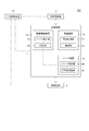
- FIG. 3 is a block diagram showing the manufacturing system SYS according to the embodiment.
- the manufacturing system SYS includes a host control device 51.
- the host controller 51 is MES (Manufacturing Execution System), MCS (Material Control System, Material Handling Control System), or the like.
- the host control device 51 comprehensively controls the storage device 1, the processing device 2, and the ceiling transport vehicle 3.
- FIG. 3 representatively shows one processing apparatus 2 provided in the manufacturing system SYS.
- the manufacturing system SYS is provided with a plurality of processing apparatuses, and the host controller 51 includes a plurality of processing apparatuses. Control the device.
- the host controller 51 supplies a control command to the ceiling transport vehicle 3 and causes the ceiling transport vehicle 3 to transport the container F.
- the host control device 51 also supplies a control command to the processing device 2 and causes the processing device 2 to execute processing.
- the host controller 51 supplies a control command to the storage device 1 to execute delivery of the container F with the overhead conveyance vehicle 3, delivery with the container F with the processing device 2, and the like.
- the storage control device 14 of the storage device 1 supplies a transfer command to the transfer control unit 27 of the transfer device 13 based on the control command from the host control device 51, and causes the transfer device 13 to transfer the container F.
- the container F delivered to the processing apparatus 2 or the container F received from the processing apparatus 2 may not need the purge process by the purge apparatus 12 of the storage apparatus 1.
- the purge process needs to be performed before the processing of the processing apparatus 2, but the container F may not be subjected to the purge process when the processed article is conveyed.
- the purging process for the container F to be passed to the processing apparatus 2 is necessary, but the purging process for the container F received from the processing apparatus 2 is not necessary. Time is wasted. Therefore, in the storage device 1, the purge determination unit 15 determines whether or not the purge process is necessary according to at least one of the carry-in source of the container F to the storage shelf 11 and the carry-out destination of the container F from the storage shelf 11.
- the storage control device 14 causes the purge determination unit 15 to perform the purge process by the purge device 12 on the container F determined to require the purge process, and the purge determination unit 15 determines that the purge process is unnecessary. On the other hand, the purge process by the purge device 12 is not executed.
- the purge device 12 of the storage device 1 may be performed in the storage device 1 as much as the purge gas is removed during the transfer.
- the purge determination unit 15 may determine the conditions for the purge process according to at least one of the carry-in source of the container F to the storage shelf 11 and the carry-out destination of the container F from the storage shelf 11.
- the purge process conditions include, for example, the flow rate of the purge gas, the supply time of the purge gas, and the like.
- the purge determination unit 15 responds to a transfer command between the loading / unloading ports 6 and 7 and the storage shelf 11 for the transfer device 13 or a transfer command between the load ports 4 and 5 and the storage shelf 11 to the transfer device 13. Based on this, the necessity of the purge process is determined.
- the transport command is a command to transport the container F from the loading / unloading port 6 to the storage shelf 11
- the container F is temporarily stored and then passed to the processing device 2.
- the article before processing is accommodated.
- the transport command is a command for transporting the container F from the load port 5 to the storage shelf 11, the container F contains an article processed by the processing device 2.
- the purge determining unit 15 specifies the carry-in source and the carry-out destination of the container F based on the conveyance command, and collates the result with reference information.
- the reference information is information that associates the carry-in source with the necessity of the purge process, or information that associates the carry-out destination with the necessity of the purge process.
- the reference information is stored in the storage unit 16, and the purge determination unit 15 determines whether or not purge processing is necessary by comparing the result of specifying the carry-in source and the carry-out destination with the reference information acquired from the storage unit 16. To do.
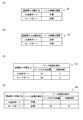
- FIG. 4 is a diagram illustrating an example of reference information according to the embodiment.
- the reference information D1 in FIG. 4A is table data in which the carry-in source to the storage shelf 11 and the necessity of purge processing are associated with each other.
- a purge process is unnecessary before the processing of the processing apparatus 2 and a purge process is required after the processing of the processing apparatus 2.
- this container F corresponds to before processing of the processing apparatus 2, and therefore the item “necessity of purge processing” is set. “Unnecessary”.
- the container F corresponds after the processing of the processing apparatus 2, and therefore the item “necessity of purge processing” is “necessary”.
- table data that associates the carry-out destination to the storage shelf 11 with the necessity of the purge process can be used.
- the “carry-out destination from the storage shelf” is “entry / exit port”
- the “carry-in source to storage shelf” corresponds to the “load port” in the reference information D1
- “necessity of purge processing” Item is “necessary”.
- the “carry-out destination from the storage shelf” is “load port”
- the “carry-in source to the storage shelf” in the reference information D1 corresponds to the “entry / exit port”.
- the “necessity” item is “unnecessary”.
- the reference information D3 in FIG. 4C is table data in which the carry-in source to the storage shelf 11 is associated with the purge processing conditions.
- the purge process conditions are the flow rate and supply time of the purge gas.
- source to storage shelf is “entry / exit port”
- flow rate of purge gas” of “condition of purge process” is “Q1”
- supply time is “T1”.
- the “loading source to the storage shelf” is “load port”
- the “purge gas flow rate” of the “purging process condition” is “Q2”
- the “supply time” is “T2”.
- the degree of purge processing may be lighter (the purge gas supply amount is smaller) than the corresponding container F after processing. Since the container F corresponding to the process has a “loading source to the storage shelf” as the “loading / unloading port”, the container F corresponding to the process has a “loading source from the storage shelf” as the “load port”. , Q1 is set to be less than Q2, or T1 is set to be shorter than T2. It should be noted that instead of “necessity of purge process” in FIG.
- “necessity of purge process” can be used to indicate the necessity of purge process, for example, “flow rate of purge gas” and “supply” By setting at least one of “time” to 0, it can also indicate that the purge process is unnecessary.
- the reference information D4 in FIG. 4D is table data that associates the carry-in source to the storage shelf 11 with the necessity / conditions of the purge process and the conditions. If the “Purchase from / to the storage shelf” is “In / Out port”, “Necessity of purge processing” is “Unnecessary”, and “Purge gas flow rate” and “Supply time” of “Purge processing conditions” are Both are “0”. In addition, when “loading source to storage shelf” is “load port”, “necessity of purge process” is “necessary”, and “purge gas flow rate” of “condition of purge process” is “Q2”. Yes “Supply time” is “T2”.
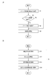
- FIG. 5A is a flowchart illustrating the purge method according to the embodiment
- FIG. 5B is a flowchart illustrating an example of the process of step S1 in FIG. 5A.
- the purge determining unit 15 determines whether or not purge processing is necessary. As shown in FIG. 5B, in step S ⁇ b> 11 of step S ⁇ b> 1, the purge determining unit 15 acquires a conveyance command for the transfer device 13. Further, in step S12, the purge determining unit 15 specifies the carry-in source of the container F to the storage shelf 11 based on the acquired conveyance command.
- the purge determining unit 15 obtains reference information (see FIG. 4) from the storage unit 16 in step S13, and in step S14, collates the carry-in source of the container F to the storage shelf 11 with the reference information, and performs purge processing. Decide whether it is necessary.
- step S2 of FIG. 5A the storage control device 14 determines whether or not to execute the purge process.
- the purge determining unit 15 determines that the purge process is necessary
- the storage control device 14 determines that the purge process is to be executed (step S2; Yes), and executes the purge process to the purge control unit 44 in step S3.
- the purge process is executed by supplying the required control command.
- the storage control apparatus 14 determines not to perform a purge process, when the purge determination part 15 determines that a purge process is unnecessary (step S2; No).
- step S4 or when it is determined not to execute the purge process step S2; No
- the storage device 1 stores the container F in the storage shelf 11.
- the storage control device 14 includes, for example, a computer system.
- the storage control device 14 reads a program stored in the storage unit 16 and executes various processes according to the control program.
- This control program stores, for example, a container F in the storage shelf 11 in a computer, performs a purge process on the container F by the purge device 12 provided in the storage shelf 11, and stores the container F in the storage shelf 11.
- control including determining whether or not purge processing is necessary and at least one of the conditions is executed.
- This program may be provided by being recorded on a computer-readable storage medium.
- the purge determination unit 15 determines whether or not the purge process is necessary according to the conveyance command to the transfer device 13, but may determine whether or not the purge process is necessary based on other information.
- the storage device 1 may acquire information on the container F from the host control device 51 or the processing device 2 and determine whether or not purge processing is necessary based on this information.
- the information on the container F is associated with, for example, an individual ID of the container F, and includes information such as the type of the article accommodated in the container F, the stage of processing, and the like.
- Japanese Patent Application No. 2015-168594 which is a Japanese patent application, and all the references cited in the above-described embodiments, etc. are incorporated as part of the description of this text.
Landscapes
- Engineering & Computer Science (AREA)
- Mechanical Engineering (AREA)
- Container, Conveyance, Adherence, Positioning, Of Wafer (AREA)
- Warehouses Or Storage Devices (AREA)
- Dram (AREA)
Abstract
Description
2 処理装置
3 天井搬送車(搬送車)
4、5 ロードポート
6、7 入出庫ポート(搬送車用ポート)
11 保管棚
12 パージ装置
13 移載装置(入出庫装置)
15 パージ決定部
F 容器
Claims (10)
- 容器を保管する保管棚と、
前記保管棚に設けられ、前記容器にパージ処理を行うことが可能なパージ装置と、
前記保管棚への前記容器の搬入元、及び前記保管棚からの前記容器の搬出先の少なくとも一方に応じて、前記パージ処理の要否および条件の少なくとも一方を決定するパージ決定部と、を備える保管装置。 - 前記保管棚への前記容器の搬入および前記保管棚からの前記容器の搬出を行う入出庫装置を備え、
前記パージ決定部は、前記入出庫装置への搬送指令に応じて、前記パージ処理の要否を決定する、請求項1に記載の保管装置。 - 前記容器に収容された物品を処理する処理装置に併設され、搬送車によって前記容器が受け渡される搬送車用ポートと、前記処理装置のロードポートとの間で受け渡される前記容器を前記保管棚に保管し、
前記パージ決定部は、前記入出庫装置に対する前記搬送車用ポートと前記保管棚との間の前記搬送指令、または前記入出庫装置に対する前記ロードポートと前記保管棚との間の前記搬送指令に基づいて、前記パージ処理の要否を決定する、請求項2に記載の保管装置。 - 前記搬送指令が、前記容器を前記搬送車用ポートから前記保管棚へ搬送させる指令である場合、前記パージ決定部は、前記搬入元が前記搬送車用ポートであると特定する、請求項3に記載の保管装置。
- 前記搬送指令が、前記容器を前記搬送車用ポートから前記保管棚へ搬送させる指令である場合、前記パージ決定部は、前記搬出先が前記ロードポートであると特定する、請求項3または請求項4に記載の保管装置。
- 前記搬送指令が、前記容器を前記ロードポートから前記保管棚へ搬送させる指令である場合、前記パージ決定部は、前記搬入元が前記ロードポートであると特定する、請求項3に記載の保管装置。
- 前記搬送指令が、前記容器を前記ロードポートから前記保管棚へ搬送させる指令である場合、前記パージ決定部は、前記搬出先が前記搬送車用ポートであると特定する、請求項3または請求項6に記載の保管装置。
- 前記パージ決定部は、前記搬出先を特定した結果を、前記搬出先と前記パージ処理の要否とを関連付けた参照情報と照合して、前記パージ処理の要否を決定する、請求項5または請求項7に記載の保管装置。
- 前記パージ決定部は、前記搬入元を特定した結果を、前記搬入元と前記パージ処理の要否とを関連付けた参照情報と照合して、前記パージ処理の要否を決定する、請求項6または請求項8に記載の保管装置。
- 容器を保管棚に保管することと、
前記保管棚に設けられるパージ装置により前記容器にパージ処理を行うことと、
前記保管棚への前記容器の搬入元、及び前記保管棚からの前記容器の搬出先の少なくとも一方に応じて、前記パージ処理の要否および条件の少なくとも一方を決定することと、を含む保管方法。
Priority Applications (7)
| Application Number | Priority Date | Filing Date | Title |
|---|---|---|---|
| IL257595A IL257595B (en) | 2015-08-28 | 2016-07-04 | Storage facility and storage method |
| SG11201801385XA SG11201801385XA (en) | 2015-08-28 | 2016-07-04 | Storage apparatus and storage method |
| EP16841269.0A EP3343597B1 (en) | 2015-08-28 | 2016-07-04 | Storage device and storage method |
| JP2017537615A JP6414338B2 (ja) | 2015-08-28 | 2016-07-04 | 保管装置および保管方法 |
| KR1020187005227A KR20180032624A (ko) | 2015-08-28 | 2016-07-04 | 보관 장치 및 보관 방법 |
| CN201680049177.8A CN107924857B (zh) | 2015-08-28 | 2016-07-04 | 保管装置和保管方法 |
| US15/755,131 US10882697B2 (en) | 2015-08-28 | 2016-07-04 | Storage apparatus and storage method |
Applications Claiming Priority (2)
| Application Number | Priority Date | Filing Date | Title |
|---|---|---|---|
| JP2015168594 | 2015-08-28 | ||
| JP2015-168594 | 2015-08-28 |
Publications (1)
| Publication Number | Publication Date |
|---|---|
| WO2017038237A1 true WO2017038237A1 (ja) | 2017-03-09 |
Family
ID=58187218
Family Applications (1)
| Application Number | Title | Priority Date | Filing Date |
|---|---|---|---|
| PCT/JP2016/069770 Ceased WO2017038237A1 (ja) | 2015-08-28 | 2016-07-04 | 保管装置および保管方法 |
Country Status (9)
| Country | Link |
|---|---|
| US (1) | US10882697B2 (ja) |
| EP (1) | EP3343597B1 (ja) |
| JP (1) | JP6414338B2 (ja) |
| KR (1) | KR20180032624A (ja) |
| CN (1) | CN107924857B (ja) |
| IL (1) | IL257595B (ja) |
| SG (1) | SG11201801385XA (ja) |
| TW (1) | TWI665142B (ja) |
| WO (1) | WO2017038237A1 (ja) |
Cited By (3)
| Publication number | Priority date | Publication date | Assignee | Title |
|---|---|---|---|---|
| KR20200028303A (ko) * | 2018-09-06 | 2020-03-16 | 도쿄엘렉트론가부시키가이샤 | 기판 처리 장치 및 퍼지 방법 |
| JP2024085030A (ja) * | 2022-12-14 | 2024-06-26 | 信越ポリマー株式会社 | 基板収納容器 |
| JP7834231B1 (ja) * | 2025-11-27 | 2026-03-23 | 平田機工株式会社 | 容器保管装置及び保管方法 |
Families Citing this family (7)
| Publication number | Priority date | Publication date | Assignee | Title |
|---|---|---|---|---|
| EP3343596B1 (en) * | 2015-08-25 | 2022-01-12 | Murata Machinery, Ltd. | Purge device, purge stocker, and purge method |
| DE102016205597B4 (de) * | 2016-04-05 | 2022-06-23 | Fabmatics Gmbh | Purge-Messsystem für FOUPs |
| JP6939990B2 (ja) * | 2018-05-23 | 2021-09-22 | 株式会社ダイフク | ピッキングシステム(picking system) |
| KR102126466B1 (ko) * | 2018-09-27 | 2020-06-24 | 크린팩토메이션 주식회사 | 이에프이엠 |
| JP7327425B2 (ja) * | 2021-02-19 | 2023-08-16 | 株式会社ダイフク | 搬送設備 |
| US11984335B2 (en) * | 2021-12-29 | 2024-05-14 | Applied Materials, Inc. | FOUP or cassette storage for hybrid substrate bonding system |
| CN114493323A (zh) * | 2022-02-11 | 2022-05-13 | 内蒙古中科装备有限公司 | 储氢容器的紧急吹扫方法、系统及介质 |
Citations (3)
| Publication number | Priority date | Publication date | Assignee | Title |
|---|---|---|---|---|
| JP2013139319A (ja) * | 2012-01-04 | 2013-07-18 | Daifuku Co Ltd | 物品保管設備 |
| JP2014027258A (ja) * | 2012-06-20 | 2014-02-06 | Tdk Corp | ロードポート装置及びefemシステム |
| JP2015029057A (ja) * | 2013-06-28 | 2015-02-12 | 株式会社日立国際電気 | 基板処理装置及び半導体装置の製造方法並びに記録媒体 |
Family Cites Families (15)
| Publication number | Priority date | Publication date | Assignee | Title |
|---|---|---|---|---|
| US5715612A (en) * | 1995-08-17 | 1998-02-10 | Schwenkler; Robert S. | Method for precision drying surfaces |
| JP2000003955A (ja) * | 1998-06-15 | 2000-01-07 | Mitsubishi Electric Corp | 半導体ウエハ収納装置 |
| JP2003092345A (ja) * | 2001-07-13 | 2003-03-28 | Semiconductor Leading Edge Technologies Inc | 基板収納容器、基板搬送システム、保管装置及びガス置換方法 |
| JP2009049286A (ja) * | 2007-08-22 | 2009-03-05 | Panasonic Corp | 半導体装置の製造管理装置および製造管理方法 |
| JP4692584B2 (ja) * | 2008-07-03 | 2011-06-01 | 村田機械株式会社 | パージ装置 |
| JP2010241515A (ja) * | 2009-04-01 | 2010-10-28 | Murata Machinery Ltd | 保管倉庫 |
| JP5083278B2 (ja) * | 2009-06-15 | 2012-11-28 | 村田機械株式会社 | 装置前自動倉庫 |
| FR2954583B1 (fr) * | 2009-12-18 | 2017-11-24 | Alcatel Lucent | Procede et dispositif de pilotage de fabrication de semi conducteurs par mesure de contamination |
| CN102194730B (zh) * | 2010-03-15 | 2015-08-05 | 三星电子株式会社 | 衬底转移容器、气体净化监视工具及具有其的半导体制造设备 |
| KR101495629B1 (ko) * | 2011-05-25 | 2015-02-25 | 무라다기카이가부시끼가이샤 | 로드 포트 장치, 반송 시스템 및 컨테이너 반출 방법 |
| JP5598734B2 (ja) * | 2012-01-06 | 2014-10-01 | 株式会社ダイフク | 物品保管設備 |
| US9695509B2 (en) * | 2012-10-23 | 2017-07-04 | Hitachi Kokusai Electric Inc. | Substrate processing apparatus, purging apparatus, method of manufacturing semiconductor device, and recording medium |
| JP5884779B2 (ja) * | 2013-06-26 | 2016-03-15 | 株式会社ダイフク | 物品保管設備 |
| JP6044467B2 (ja) * | 2013-06-26 | 2016-12-14 | 株式会社ダイフク | 保管システム |
| JP5884780B2 (ja) * | 2013-06-26 | 2016-03-15 | 株式会社ダイフク | 保管設備 |
-
2016
- 2016-07-04 KR KR1020187005227A patent/KR20180032624A/ko not_active Ceased
- 2016-07-04 JP JP2017537615A patent/JP6414338B2/ja active Active
- 2016-07-04 US US15/755,131 patent/US10882697B2/en active Active
- 2016-07-04 CN CN201680049177.8A patent/CN107924857B/zh active Active
- 2016-07-04 WO PCT/JP2016/069770 patent/WO2017038237A1/ja not_active Ceased
- 2016-07-04 EP EP16841269.0A patent/EP3343597B1/en active Active
- 2016-07-04 IL IL257595A patent/IL257595B/en unknown
- 2016-07-04 SG SG11201801385XA patent/SG11201801385XA/en unknown
- 2016-08-26 TW TW105127431A patent/TWI665142B/zh active
Patent Citations (3)
| Publication number | Priority date | Publication date | Assignee | Title |
|---|---|---|---|---|
| JP2013139319A (ja) * | 2012-01-04 | 2013-07-18 | Daifuku Co Ltd | 物品保管設備 |
| JP2014027258A (ja) * | 2012-06-20 | 2014-02-06 | Tdk Corp | ロードポート装置及びefemシステム |
| JP2015029057A (ja) * | 2013-06-28 | 2015-02-12 | 株式会社日立国際電気 | 基板処理装置及び半導体装置の製造方法並びに記録媒体 |
Non-Patent Citations (1)
| Title |
|---|
| See also references of EP3343597A4 * |
Cited By (8)
| Publication number | Priority date | Publication date | Assignee | Title |
|---|---|---|---|---|
| KR20200028303A (ko) * | 2018-09-06 | 2020-03-16 | 도쿄엘렉트론가부시키가이샤 | 기판 처리 장치 및 퍼지 방법 |
| JP2020043132A (ja) * | 2018-09-06 | 2020-03-19 | 東京エレクトロン株式会社 | 基板処理装置及びパージ方法 |
| US11367642B2 (en) | 2018-09-06 | 2022-06-21 | Tokyo Electron Limited | Substrate processing apparatus and purging method |
| JP7090513B2 (ja) | 2018-09-06 | 2022-06-24 | 東京エレクトロン株式会社 | 基板処理装置及びパージ方法 |
| KR102521265B1 (ko) | 2018-09-06 | 2023-04-14 | 도쿄엘렉트론가부시키가이샤 | 기판 처리 장치 및 퍼지 방법 |
| JP2024085030A (ja) * | 2022-12-14 | 2024-06-26 | 信越ポリマー株式会社 | 基板収納容器 |
| JP7832886B2 (ja) | 2022-12-14 | 2026-03-18 | 信越ポリマー株式会社 | 基板収納容器 |
| JP7834231B1 (ja) * | 2025-11-27 | 2026-03-23 | 平田機工株式会社 | 容器保管装置及び保管方法 |
Also Published As
| Publication number | Publication date |
|---|---|
| JPWO2017038237A1 (ja) | 2018-08-02 |
| KR20180032624A (ko) | 2018-03-30 |
| US20180244470A1 (en) | 2018-08-30 |
| EP3343597B1 (en) | 2022-04-20 |
| CN107924857A (zh) | 2018-04-17 |
| SG11201801385XA (en) | 2018-03-28 |
| IL257595A (en) | 2018-04-30 |
| EP3343597A1 (en) | 2018-07-04 |
| TW201711935A (zh) | 2017-04-01 |
| US10882697B2 (en) | 2021-01-05 |
| IL257595B (en) | 2022-07-01 |
| EP3343597A4 (en) | 2019-05-01 |
| TWI665142B (zh) | 2019-07-11 |
| JP6414338B2 (ja) | 2018-10-31 |
| CN107924857B (zh) | 2022-04-05 |
Similar Documents
| Publication | Publication Date | Title |
|---|---|---|
| JP6414338B2 (ja) | 保管装置および保管方法 | |
| JP6562078B2 (ja) | パージ装置、パージストッカ、及びパージ方法 | |
| US9701431B2 (en) | Load port device, transport system, and container carrying out method | |
| US20190096702A1 (en) | Substrate processing apparatus, substrate processing method, and computer storage medium | |
| WO2017033546A1 (ja) | パージ装置、パージストッカ、及びパージ方法 | |
| KR102521265B1 (ko) | 기판 처리 장치 및 퍼지 방법 | |
| US11608229B2 (en) | Storage system and purge method in storage system | |
| US10610905B2 (en) | Purge device, purge stocker, and cleaning method | |
| KR101353148B1 (ko) | 기판 처리 장치, 기판 처리 장치 제어 프로그램 및 반도체 장치의 제조 방법 | |
| US12451344B2 (en) | Substrate processing method | |
| JP6478878B2 (ja) | 基板処理装置及び基板搬送方法並びに基板搬送プログラムを記憶したコンピュータ読み取り可能な記憶媒体 | |
| KR101992825B1 (ko) | 기판 처리 장치의 에이징 기판 교체 방법 | |
| KR102166348B1 (ko) | 이송 장치의 동작 제어 방법 | |
| KR102181492B1 (ko) | 이송 장치의 동작 제어 방법 | |
| JP2004319889A (ja) | 製造対象物の受け渡し装置および製造対象物の受け渡し方法 | |
| US20250218839A1 (en) | Stocker device and substrate processing apparatus | |
| JP4657528B2 (ja) | 処理システムおよび処理方法 | |
| KR20260057407A (ko) | 퍼지 노즐, 기판 처리 장치, 기판 수용기 퍼지 방법, 반도체 장치의 제조 방법 및 프로그램 | |
| JP2008100802A (ja) | 基板保管庫 |
Legal Events
| Date | Code | Title | Description |
|---|---|---|---|
| 121 | Ep: the epo has been informed by wipo that ep was designated in this application |
Ref document number: 16841269 Country of ref document: EP Kind code of ref document: A1 |
|
| ENP | Entry into the national phase |
Ref document number: 2017537615 Country of ref document: JP Kind code of ref document: A |
|
| WWE | Wipo information: entry into national phase |
Ref document number: 257595 Country of ref document: IL |
|
| ENP | Entry into the national phase |
Ref document number: 20187005227 Country of ref document: KR Kind code of ref document: A |
|
| WWE | Wipo information: entry into national phase |
Ref document number: 11201801385X Country of ref document: SG Ref document number: 15755131 Country of ref document: US |
|
| NENP | Non-entry into the national phase |
Ref country code: DE |