WO2017038543A1 - 音声処理装置および方法、並びにプログラム - Google Patents
音声処理装置および方法、並びにプログラム Download PDFInfo
- Publication number
- WO2017038543A1 WO2017038543A1 PCT/JP2016/074453 JP2016074453W WO2017038543A1 WO 2017038543 A1 WO2017038543 A1 WO 2017038543A1 JP 2016074453 W JP2016074453 W JP 2016074453W WO 2017038543 A1 WO2017038543 A1 WO 2017038543A1
- Authority
- WO
- WIPO (PCT)
- Prior art keywords
- angle
- unit
- correction
- microphone array
- spatial frequency
- Prior art date
- Legal status (The legal status is an assumption and is not a legal conclusion. Google has not performed a legal analysis and makes no representation as to the accuracy of the status listed.)
- Ceased
Links
Images


Classifications
-
- H—ELECTRICITY
- H04—ELECTRIC COMMUNICATION TECHNIQUE
- H04R—LOUDSPEAKERS, MICROPHONES, GRAMOPHONE PICK-UPS OR LIKE ACOUSTIC ELECTROMECHANICAL TRANSDUCERS; ELECTRIC HEARING AIDS; PUBLIC ADDRESS SYSTEMS
- H04R1/00—Details of transducers, loudspeakers or microphones
- H04R1/20—Arrangements for obtaining desired frequency or directional characteristics
- H04R1/32—Arrangements for obtaining desired frequency or directional characteristics for obtaining desired directional characteristic only
- H04R1/40—Arrangements for obtaining desired frequency or directional characteristics for obtaining desired directional characteristic only by combining a number of identical transducers
-
- H—ELECTRICITY
- H04—ELECTRIC COMMUNICATION TECHNIQUE
- H04R—LOUDSPEAKERS, MICROPHONES, GRAMOPHONE PICK-UPS OR LIKE ACOUSTIC ELECTROMECHANICAL TRANSDUCERS; ELECTRIC HEARING AIDS; PUBLIC ADDRESS SYSTEMS
- H04R1/00—Details of transducers, loudspeakers or microphones
- H04R1/20—Arrangements for obtaining desired frequency or directional characteristics
- H04R1/32—Arrangements for obtaining desired frequency or directional characteristics for obtaining desired directional characteristic only
- H04R1/40—Arrangements for obtaining desired frequency or directional characteristics for obtaining desired directional characteristic only by combining a number of identical transducers
- H04R1/406—Arrangements for obtaining desired frequency or directional characteristics for obtaining desired directional characteristic only by combining a number of identical transducers microphones
-
- H—ELECTRICITY
- H04—ELECTRIC COMMUNICATION TECHNIQUE
- H04R—LOUDSPEAKERS, MICROPHONES, GRAMOPHONE PICK-UPS OR LIKE ACOUSTIC ELECTROMECHANICAL TRANSDUCERS; ELECTRIC HEARING AIDS; PUBLIC ADDRESS SYSTEMS
- H04R3/00—Circuits for transducers
-
- H—ELECTRICITY
- H04—ELECTRIC COMMUNICATION TECHNIQUE
- H04R—LOUDSPEAKERS, MICROPHONES, GRAMOPHONE PICK-UPS OR LIKE ACOUSTIC ELECTROMECHANICAL TRANSDUCERS; ELECTRIC HEARING AIDS; PUBLIC ADDRESS SYSTEMS
- H04R2430/00—Signal processing covered by H04R, not provided for in its groups
- H04R2430/20—Processing of the output signals of the acoustic transducers of an array for obtaining a desired directivity characteristic
-
- H—ELECTRICITY
- H04—ELECTRIC COMMUNICATION TECHNIQUE
- H04S—STEREOPHONIC SYSTEMS
- H04S2400/00—Details of stereophonic systems covered by H04S but not provided for in its groups
- H04S2400/15—Aspects of sound capture and related signal processing for recording or reproduction
Definitions
- the present technology relates to an audio processing device, method, and program, and more particularly, to an audio processing device, method, and program that can reproduce a sound field more appropriately.
- Patent Document 1 As a technology related to such contents, for example, by controlling an image of a wide field of view and smoothing the movement of the field of view, a technology for preventing image sickness and lost spatial spacing due to image blurring obtained by an omnidirectional camera Has been proposed (see, for example, Patent Document 1).
- the microphone array when recording an omnidirectional sound field using an annular or spherical microphone array, the microphone array may be attached to a moving body such as a person. In such a case, the movement and movement of the moving body cause rotation and blurring in the direction of the microphone array, so that the recorded sound field also includes rotation and shaking.
- the present technology has been made in view of such a situation, and is intended to reproduce a sound field more appropriately.
- the sound processing device includes a correction unit that corrects a sound collection signal obtained by collecting sound with a microphone array based on direction information indicating the direction of the microphone array.
- the direction information can be information indicating an angle of the direction of the microphone array from a predetermined reference direction.
- the correction unit can correct the spatial frequency spectrum obtained from the collected sound signal based on the direction information.
- the correction unit can perform the correction at the time of spatial frequency conversion on the time frequency spectrum obtained from the sound collection signal.
- the correction unit can correct the angle indicating the direction of the microphone array in the spherical harmonic function used for the spatial frequency conversion based on the direction information.
- the correction unit can perform the correction at the time of inverse spatial frequency conversion on the spatial frequency spectrum obtained from the sound collection signal.
- the correction unit can correct the angle indicating the direction of the speaker array for reproducing the sound based on the collected sound signal in the spherical harmonic function used for the inverse spatial frequency conversion based on the direction information.
- the correction unit can correct the sound collection signal in accordance with displacement, angular velocity, or acceleration per unit time of the microphone array.
- the microphone array can be an annular microphone array or a spherical microphone array.
- the sound processing method or program includes a step of correcting a sound collection signal obtained by collecting sound with a microphone array based on direction information indicating the direction of the microphone array.
- a sound collection signal obtained by collecting sound with a microphone array is corrected based on direction information indicating the direction of the microphone array.
- the sound field can be reproduced more appropriately.
- This technology records a sound field with a microphone array including a plurality of microphones in a sound collection space, and a speaker array including a plurality of speakers arranged in a reproduction space based on a multi-channel sound collection signal obtained as a result. It reproduces the sound field.
- the microphone array may be any one that is configured by arranging a plurality of microphones, such as an annular microphone array in which a plurality of microphones are arranged in a ring shape, or a spherical microphone array in which a plurality of microphones are arranged in a spherical shape. It may be something like this.
- any speaker array may be used as long as a plurality of speakers are arranged side by side, such as a plurality of speakers arranged in a ring shape or a plurality of speakers arranged in a spherical shape. There may be.
- the speaker array SPA11 including a plurality of speakers reproduces sound based on the sound collection signal obtained by the sound collection by the microphone array MKA11 in the reproduction space as indicated by the arrow A12. That is, it is assumed that the sound field is reproduced by the speaker array SPA11.
- a viewer that is, a user U11 who is an audio listener is located at a position surrounded by each speaker constituting the speaker array SPA11, and the user U11 is viewed from the user U11 when reproducing the audio. Sound from sound source AS11 is heard from the right direction. Therefore, it can be seen that the sound field is appropriately reproduced in this example.
- the sound image of the sound source AS11 that should be localized at the position indicated by the arrow B11 is rotated and moved by the inclination of the microphone array MKA11, that is, by the angle ⁇ , and is localized at the position indicated by the arrow B12. End up.
- the microphone array MKA11 rotates from the reference state as described above, or if the microphone array MKA11 is shaken, the sound field reproduced based on the collected sound signal may also be rotated or shaken. It will occur.
- rotation and shaking of the recorded sound field are corrected by using direction information indicating the direction of the microphone array when recording the sound field.
- the direction of the recorded sound field can be fixed in a certain direction, and the sound field can be reproduced more appropriately. become.
- a method of acquiring direction information indicating the direction of the microphone array at the time of recording a sound field a method of providing a gyro sensor or an acceleration sensor in the microphone array can be considered.
- a device in which a camera device capable of photographing all directions or a part of directions and a microphone array is used is used, and based on image information obtained by photographing with the camera device, that is, based on the photographed image.
- the direction of the microphone array may be calculated.
- a method for reproducing the sound field of content regardless of the viewpoint of the mobile object to which the microphone array is attached, and the method for reproducing the content from the viewpoint of the mobile object to which the microphone array is attached are provided.
- a method to reproduce the sound field can be considered.
- the recorded sound field can be fixed in a certain direction as needed regardless of the direction of the microphone array.
- the sound field can be reproduced more appropriately in a playback system in which the viewer can view the recorded content from a free viewpoint.
- FIG. 2 is a diagram illustrating a configuration example of an embodiment of a recorded sound field direction controller to which the present technology is applied.
- the recording sound field direction controller 11 shown in FIG. 2 has a recording device 21 arranged in the sound collection space and a reproduction device 22 arranged in the reproduction space.
- the recording device 21 records the sound field of the sound collection space, and supplies a signal obtained as a result to the reproducing device 22.
- the reproducing device 22 receives the signal from the recording device 21, and based on the signal. To reproduce the sound field of the sound collection space.
- the recording device 21 includes a microphone array 31, a time frequency analysis unit 32, a direction correction unit 33, a spatial frequency analysis unit 34, and a communication unit 35.
- the microphone array 31 includes, for example, an annular microphone array or a spherical microphone array.
- the microphone array 31 collects sound in a sound collection space as content, and a collected sound signal that is a multi-channel sound signal obtained as a result is a time-frequency analysis unit 32. To supply.
- the time frequency analysis unit 32 performs time frequency conversion on the collected sound signal supplied from the microphone array 31 and supplies the time frequency spectrum obtained as a result to the spatial frequency analysis unit 34.
- the direction correcting unit 33 acquires part or all of the correction mode information, microphone arrangement information, image information, and sensor information as necessary, and corrects the direction of the recording device 21 based on the acquired information.
- the correction angle is calculated.
- the direction correction unit 33 supplies the microphone arrangement information and the correction angle to the spatial frequency analysis unit 34.
- the correction mode information is information indicating which mode is designated as the direction correction mode for correcting the direction of the recording sound field, that is, the direction of the recording device 21.
- the rotational shake correction mode is a mode for correcting the rotation and shake of the recording device 21.
- the rotational shake correction mode is for reproducing content with the recorded sound field fixed in a certain direction, that is, reproducing the sound field. Selected.
- the shake correction mode is a mode for correcting only the shake of the recording device 21.
- the shake correction mode is selected when reproducing the content from the viewpoint of the moving object to which the recording device 21 is attached, that is, reproducing the sound field. Is done.
- the no correction mode is a mode in which neither rotation nor shaking of the recording device 21 is corrected.
- the microphone arrangement information is angle information indicating the direction serving as a predetermined reference of the recording device 21, that is, the microphone array 31.
- This microphone arrangement information is the direction of the microphone array 31 at a predetermined time (hereinafter, also referred to as a reference time), such as when the recording device 21 starts recording a sound field, that is, collecting sound, and more specifically, the microphone array.
- 31 is information indicating the direction of each microphone constituting the unit 31. Therefore, in this case, for example, if the recording device 21 remains stationary during recording of the sound field, the direction of each microphone of the microphone array 31 during recording remains the direction indicated by the microphone arrangement information.
- the image information is, for example, an image taken by a camera device (not shown) provided integrally with the microphone array 31 in the recording device 21.
- the sensor information is information indicating the amount of rotation (displacement) of the recording device 21 obtained by a gyro sensor (not shown) provided integrally with the microphone array 31 in the recording device 21, for example, the microphone array 31.
- the spatial frequency analysis unit 34 performs spatial frequency conversion on the time frequency spectrum supplied from the time frequency analysis unit 32 using the microphone arrangement information and the correction angle supplied from the direction correction unit 33, and obtains the result.
- the obtained spatial frequency spectrum is supplied to the communication unit 35.
- the communication unit 35 transmits the spatial frequency spectrum supplied from the spatial frequency analysis unit 34 to the playback device 22 by wire or wireless.
- the playback device 22 includes a communication unit 41, a spatial frequency synthesis unit 42, a time frequency synthesis unit 43, and a speaker array 44.
- the communication unit 41 receives the spatial frequency spectrum transmitted from the communication unit 35 of the recording device 21 and supplies it to the spatial frequency synthesis unit 42.
- the spatial frequency synthesis unit 42 spatially synthesizes the spatial frequency spectrum supplied from the communication unit 41 based on the speaker arrangement information supplied from the outside, and the resulting time frequency spectrum is sent to the time frequency synthesis unit 43. Supply.
- the speaker arrangement information is angle information indicating the direction of the speaker array 44, more specifically the direction of each speaker constituting the speaker array 44.
- the time frequency synthesizer 43 performs time frequency synthesis on the time frequency spectrum supplied from the spatial frequency synthesizer 42 and supplies the resulting time signal to the speaker array 44 as a speaker drive signal.
- the speaker array 44 is composed of an annular speaker array, a spherical speaker array, or the like composed of a plurality of speakers, and reproduces sound based on the speaker drive signal supplied from the time-frequency synthesis unit 43.
- the time-frequency analysis unit 32 is a multi-channel sound collection signal s (i, n t ) obtained by collecting sound by each microphone (hereinafter also referred to as a microphone unit) constituting the microphone array 31. Is subjected to time-frequency conversion using DFT (Discrete Fourier Transform) by calculating the following equation (1) to obtain a time-frequency spectrum S (i, n tf ).
- DFT Discrete Fourier Transform
- I indicates the number of microphone units constituting the microphone array 31, and n t indicates a time index.
- n tf represents a time frequency index
- M t represents the number of DFT samples
- j represents a pure imaginary number
- the time frequency analysis unit 32 supplies the time frequency spectrum S (i, n tf ) obtained by the time frequency conversion to the spatial frequency analysis unit 34.
- the direction correction unit 33 acquires correction mode information, microphone arrangement information, image information, and sensor information, and calculates a correction angle for correcting the direction of the recording device 21, that is, microphone arrangement information, based on the acquired information. Then, the microphone arrangement information and the correction angle are supplied to the spatial frequency analysis unit 34.
- each angle information such as angle information indicating the direction of each microphone unit of the microphone array 31 indicated by the microphone arrangement information, and angle information indicating the direction of the microphone array 31 at a predetermined time obtained from image information or sensor information is an azimuth angle. And expressed by the elevation angle.
- a straight line connecting the microphone unit MU11 constituting the predetermined microphone array 31 and the origin O is a straight line LN
- a straight line obtained by projecting the straight line LN onto the xy plane from the z-axis direction is a straight line LN ′.
- an angle ⁇ formed by the x-axis and the straight line LN ′ is an azimuth indicating the direction of the microphone unit MU11 as viewed from the origin O on the xy plane. Further, an angle ⁇ formed by the xy plane and the straight line LN is an elevation angle indicating the direction of the microphone unit MU11 when viewed from the origin O in a plane perpendicular to the xy plane.
- the direction of the microphone array 31 at the reference time that is, the direction of the microphone array 31 serving as a predetermined reference is the reference direction
- each angle information is represented by an azimuth angle and an elevation angle from the reference direction.
- the reference direction is represented by an elevation angle ⁇ ref and an azimuth angle ⁇ ref , and hereinafter also referred to as a reference direction ( ⁇ ref , ⁇ ref ).
- the microphone arrangement information includes information indicating the reference direction of each microphone unit constituting the microphone array 31, that is, the direction of each microphone unit at the reference time.
- the information indicating the direction of the microphone unit whose microphone index is i is the angle ( ⁇ i) indicating the relative direction of the microphone unit with respect to the reference direction ( ⁇ ref , ⁇ ref ) at the reference time.
- ⁇ i is the elevation angle in the direction of the microphone unit viewed from the reference direction ( ⁇ ref , ⁇ ref )
- ⁇ i is the azimuth angle in the direction of the microphone unit viewed from the reference direction ( ⁇ ref , ⁇ ref ).
- the direction correcting unit 33 uses a reference direction ( ⁇ ref ) at a predetermined time (hereinafter also referred to as a processing target time) at the time of recording a sound field different from the reference time based on at least one of image information and sensor information. , ⁇ ref ), the rotation angle ( ⁇ , ⁇ ) of the microphone array 31 is obtained.
- the rotation angle ( ⁇ , ⁇ ) is angle information indicating the relative direction of the microphone array 31 with respect to the reference direction ( ⁇ ref , ⁇ ref ) at the processing target time.
- the elevation angle ⁇ constituting the rotation angle ( ⁇ , ⁇ ) is the elevation angle in the direction of the microphone array 31 viewed from the reference direction ( ⁇ ref , ⁇ ref ), and the azimuth angle ⁇ constituting the rotation angle ( ⁇ , ⁇ ). Is an azimuth angle in the direction of the microphone array 31 viewed from the reference direction ( ⁇ ref , ⁇ ref ).
- the direction correction unit 33 acquires an image captured by the camera device at the processing target time as image information, and based on the image information, the microphone array 31, that is, the displacement from the reference direction of the recording device 21 by image recognition or the like.
- the rotation angle ( ⁇ , ⁇ ) is calculated by detecting it.
- the direction correction unit 33 calculates the rotation angle ( ⁇ , ⁇ ) by detecting the rotation direction and the rotation amount from the reference direction of the recording device 21.
- the direction correction unit 33 acquires, as sensor information, the angular velocity output by the gyro sensor at the processing target time, that is, information indicating the rotation angle per unit time, and performs integral calculation based on the acquired sensor information as necessary.
- the rotation angle ( ⁇ , ⁇ ) is calculated by performing the above.
- the example which calculates rotation angle ((theta), (phi)) based on the sensor information obtained from the gyro sensor (angular velocity sensor) was demonstrated here.
- the rotation angle ( ⁇ , ⁇ ) may be calculated by acquiring the acceleration that is the output of the acceleration sensor, that is, the speed change per unit time as sensor information.
- the rotation angle ( ⁇ , ⁇ ) obtained as described above is direction information indicating the angle of the direction of the microphone array 31 from the reference direction ( ⁇ ref , ⁇ ref ) at the processing target time.
- the direction correction unit 33 corrects microphone placement information, that is, correction angles ( ⁇ , ⁇ ) for correcting the angles ( ⁇ i , ⁇ i ) of each microphone unit based on the correction mode information and the rotation angles ( ⁇ , ⁇ ). ) Is calculated.
- ⁇ of the correction angle ( ⁇ , ⁇ ) is the correction angle of the elevation angle ⁇ i of the angle ( ⁇ i , ⁇ i ) of the microphone unit
- ⁇ of the correction angle ( ⁇ , ⁇ ) is the angle of the microphone unit. This is the correction angle of the azimuth angle ⁇ i of ( ⁇ i , ⁇ i ).
- the direction correction unit 33 outputs the correction angles ( ⁇ , ⁇ ) thus obtained and the angles ( ⁇ i , ⁇ i ) of the microphone units, which are microphone arrangement information, to the spatial frequency analysis unit 34.
- the direction correction unit 33 directly uses the rotation angle ( ⁇ , ⁇ ) as the correction angle ( ⁇ , ⁇ ) as shown in the following equation (2). ).
- the rotation angle ( ⁇ , ⁇ ) is directly used as the correction angle ( ⁇ , ⁇ ). This is because if the spatial frequency analysis unit 34 corrects the angle ( ⁇ i , ⁇ i ) of the microphone unit by the amount of rotation of the microphone unit, that is, the correction angle ( ⁇ , ⁇ ), the rotation of the microphone unit. This is because the camera shake can be corrected. That is, the rotation and shake of the microphone unit included in the time frequency spectrum S (i, ntf ) are corrected, and an appropriate spatial frequency spectrum can be obtained.
- the direction indicated by the arrow Q11 is the direction of the azimuth angle ⁇ ref of the reference direction ( ⁇ ref , ⁇ ref ), and the direction of the azimuth angle serving as the reference of the microphone unit MU21 is also the direction indicated by the arrow Q11.
- the annular microphone array MKA21 rotates as indicated by the arrow A22, and the direction of the azimuth angle of the microphone unit MU21 becomes the direction indicated by the arrow Q12 at the processing target time.
- the direction of the microphone unit MU21 changes by an angle ⁇ in the direction of the azimuth angle.
- This angle ⁇ is the azimuth angle ⁇ constituting the rotation angle ( ⁇ , ⁇ ).
- the angle ⁇ corresponding to the change in the azimuth angle of the microphone unit MU21 is set as the correction angle ⁇ by the above-described equation (2).
- the angle after correction of the microphone unit angle ( ⁇ i , ⁇ i ) by the correction angle ( ⁇ , ⁇ ) is ( ⁇ i ′, ⁇ i ′)
- the angle indicating the direction of each microphone unit at the processing target time viewed from the reference direction ( ⁇ ref , ⁇ ref ) is the corrected microphone unit angle ( ⁇ i ′, ⁇ i ′).
- the direction correction unit 33 when the direction correction mode indicated by the correction mode information is the shake correction mode, the direction correction unit 33 generates a shake for each direction of the azimuth direction and the elevation direction for the microphone array 31, that is, each microphone unit.
- the shake detection is performed by determining whether or not the rotation angle (change amount) of the microphone unit per unit time, that is, the recording device 21, has exceeded a predetermined threshold value representing the shake range.
- the direction correction unit 33 compares the elevation angle ⁇ constituting the rotation angle ( ⁇ , ⁇ ) of the microphone array 31 with a predetermined threshold ⁇ thres , and when the following expression (3) is satisfied: That is, when the amount of rotation in the elevation angle direction is less than the threshold value ⁇ thres, it is determined that a shake has occurred in the elevation angle direction.
- the absolute value of the elevation angle ⁇ which is the rotation angle in the elevation direction of the recording device 21 per unit time, calculated from the displacement, angular velocity, acceleration, etc. of the recording device 21 obtained from the image information and sensor information. Is less than the threshold ⁇ thres , it is determined that the movement of the recording device 21 in the elevation angle direction is a shake.
- the direction correction unit 33 directly converts the elevation angle ⁇ of the rotation angle ( ⁇ , ⁇ ) with respect to the elevation angle direction as the correction angle ( ⁇ , ⁇ ). Used as the correction angle ⁇ of the elevation angle of ⁇ , ⁇ ).
- the direction correction unit 33 updates (corrects) the elevation angle ⁇ ref in the reference direction ( ⁇ ref , ⁇ ref ) according to the following equation (4).
- the elevation angle ⁇ ref ′ indicates the elevation angle ⁇ ref before update. Therefore, in the calculation of Expression (4), the elevation angle ⁇ constituting the rotation angle ( ⁇ , ⁇ ) of the microphone array 31 is added to the elevation angle ⁇ ref ′ before update to obtain a new elevation angle ⁇ ref after update. ing.
- the direction correction unit 33 corrects the azimuth correction angle ⁇ of the correction angle ( ⁇ , ⁇ ) in the azimuth direction as well as the elevation direction. Ask for.
- the direction correction unit 33 compares the azimuth angle ⁇ constituting the rotation angle ( ⁇ , ⁇ ) of the microphone array 31 with a predetermined threshold ⁇ thres , and when the following equation (5) is satisfied, that is, the azimuth direction When the rotation amount in the angular direction is less than the threshold value ⁇ thres, it is determined that the shake has occurred in the azimuth direction.
- the direction correction unit 33 sets the azimuth angle ⁇ of the rotation angle ( ⁇ , ⁇ ) as it is in the azimuth direction as shown in the equation (2).
- the correction angle ⁇ is used as the correction angle ⁇ of the azimuth angle of the correction angle ( ⁇ , ⁇ ).
- the direction correction unit 33 updates (corrects) the azimuth angle ⁇ ref in the reference direction ( ⁇ ref , ⁇ ref ) according to the following equation (6).
- the azimuth angle ⁇ ref ′ indicates the azimuth angle ⁇ ref before update. Therefore, in the calculation of Expression (6), the azimuth angle ⁇ constituting the rotation angle ( ⁇ , ⁇ ) of the microphone array 31 is added to the azimuth angle ⁇ ref ′ before update, and a new azimuth angle ⁇ after update is obtained. It is ref .
- FIG. 5 it is assumed that attention is paid to the azimuth angle of the microphone unit MU21 constituting the annular microphone array MKA21 as the microphone array 31.
- FIG. 5 parts corresponding to those in FIG. 4 are denoted by the same reference numerals, and description thereof is omitted as appropriate.
- the direction shown by the arrow Q11 is the direction of the azimuth angle ⁇ ref of the reference direction ( ⁇ ref , ⁇ ref ), and the direction of the azimuth angle serving as the reference of the microphone unit MU21 is also the direction shown by the arrow Q11.
- the direction shown by the arrow Q11 is the direction of the azimuth angle ⁇ ref of the reference direction ( ⁇ ref , ⁇ ref ), and the direction of the azimuth angle serving as the reference of the microphone unit MU21 is also the direction shown by the arrow Q11.
- the angle formed between the straight line in the direction indicated by the arrow Q21 and the straight line in the direction indicated by the arrow Q11 is an angle of the threshold ⁇ thres .
- the straight line in the direction indicated by the arrow Q22 and the straight line in the direction indicated by the arrow Q11 Is the angle of the threshold ⁇ thres .
- the direction of the azimuth angle of the microphone unit MU21 at the processing target time is a direction between the direction indicated by the arrow Q21 and the direction indicated by the arrow Q22
- the rotation amount of the microphone unit MU21 in the azimuth angle direction is Since it is small enough, it can be said that the movement of the microphone unit MU21 is caused by shaking.
- the direction of the azimuth angle of the microphone unit MU21 at the processing target time changes by the angle ⁇ from the reference direction to the direction indicated by the arrow Q23 as indicated by the arrow A32.
- the direction indicated by the arrow Q23 is a direction between the direction indicated by the arrow Q21 and the direction indicated by the arrow Q22, and the above-described formula (5) is established. Accordingly, the movement of the microphone unit MU21 in this case is caused by the shake, and the correction angle ⁇ of the azimuth angle of the microphone unit MU21 is obtained by the above-described equation (2).
- the direction indicated by the arrow Q24 is not a direction between the direction indicated by the arrow Q21 and the direction indicated by the arrow Q22, and the above-described formula (5) is not established. That is, moving more than the angle of the microphone units MU21 is indicated by the threshold phi thres azimuthally.
- the movement of the microphone unit MU21 in this case is caused by rotation, and the azimuth correction angle ⁇ of the microphone unit MU21 is set to zero.
- the azimuth angle ⁇ i ′ of the angle ( ⁇ i ′, ⁇ i ′) of the microphone unit MU21 after the direction correction remains ⁇ i .
- the azimuth angle ⁇ ref in the reference direction ( ⁇ ref , ⁇ ref ) is updated by the above-described equation (6).
- the direction of the azimuth angle ⁇ ref of the reference direction ( ⁇ ref , ⁇ ref ) before the update is the direction of the azimuth angle of the microphone unit MU21 before the rotational movement, that is, the direction indicated by the arrow Q11.
- direction of azimuth angle of the microphone units MU21 after the movement, i.e. the direction indicated by the arrow Q24 is the direction of the azimuth angle phi ref updated.
- the microphone unit MU21 Is detected in the azimuth direction.
- the direction correction unit 33 detects the shake independently in the azimuth angle direction and the elevation angle direction, and obtains the correction angle of the microphone unit.
- the spatial frequency analysis unit 34 obtains from the image information and sensor information per unit time of the recording device 21.
- the spatial frequency spectrum is corrected at the time of spatial frequency conversion in accordance with the displacement, angular velocity, acceleration, and the like.
- the correction of the spatial frequency spectrum is realized by correcting the angle ( ⁇ i , ⁇ i ) of the microphone unit with the correction angle ( ⁇ , ⁇ ).
- the shake correction mode by detecting the shake, the shake and the rotation of the recording device 21 can be separated (differentiated) and only the shake can be corrected. As a result, the sound field can be reproduced more appropriately.
- the detection of the shake of the recording device 21, that is, the shake of the microphone unit is not limited to the example described above, and may be performed by any other method.
- the direction correction unit 33 corrects the elevation correction angle ⁇ constituting the correction angle ( ⁇ , ⁇ ) as shown in the following equation (7).
- the correction angle ⁇ of the azimuth is set to 0.
- the angle ( ⁇ i , ⁇ i ) of the microphone unit is directly used as the corrected angle ( ⁇ i ′, ⁇ i ′) of each microphone unit. That is, in the no correction mode, the angle ( ⁇ i , ⁇ i ) of each microphone unit is not corrected.
- FIG. 6 it is assumed that attention is paid to the azimuth angle of the microphone unit MU21 constituting the annular microphone array MKA21 as the microphone array 31.
- FIG. 6 parts corresponding to those in FIG. 4 are denoted by the same reference numerals, and description thereof will be omitted as appropriate.
- the direction indicated by the arrow Q11 is the direction of the azimuth angle ⁇ ref of the reference direction ( ⁇ ref , ⁇ ref ), and the direction of the azimuth angle of the reference microphone unit MU21 is also the direction indicated by the arrow Q11.
- the direction indicated by the arrow Q11 is the direction of the azimuth angle ⁇ ref of the reference direction ( ⁇ ref , ⁇ ref )
- the direction of the azimuth angle of the reference microphone unit MU21 is also the direction indicated by the arrow Q11.
- the annular microphone array MKA21 rotates as indicated by the arrow A42, and the direction of the azimuth angle of the microphone unit MU21 becomes the direction indicated by the arrow Q12 at the processing target time.
- the direction of the microphone unit MU21 changes by an angle ⁇ in the direction of the azimuth angle.
- the spatial frequency analysis unit 34 uses the microphone arrangement information and the correction angle ( ⁇ , ⁇ ) supplied from the direction correction unit 33 to the time frequency spectrum S (i, n tf ) supplied from the time frequency analysis unit 32. On the other hand, spatial frequency conversion is performed.
- the spherical harmonic series expansion is used to convert the time frequency spectrum S (i, n tf ) into the spatial frequency spectrum S SP (n tf , n sf ).
- the spatial frequency spectrum S SP (n tf, n sf ) n tf in represents time frequency index
- n sf represents the spatial frequency index.
- the sound field P on a certain sphere can be expressed as shown in the following equation (8).
- Equation (8) Y represents a spherical harmonic function matrix, W represents a weighting coefficient based on the radius of the sphere and the order of spatial frequency, and B represents a spatial frequency spectrum.
- Y represents a spherical harmonic function matrix
- W represents a weighting coefficient based on the radius of the sphere and the order of spatial frequency
- B represents a spatial frequency spectrum.
- the spatial frequency spectrum B can be obtained by calculating the following equation (9).
- the calculation of equation (9) corresponds to spatial frequency conversion.
- Y + indicates a pseudo inverse matrix of the spherical harmonic function matrix Y, which is obtained by the following equation (10), where Y T is a transposed matrix of the spherical harmonic function matrix Y.
- the spatial frequency spectrum S SP (n tf , n sf ) can be obtained by the following equation (11).
- the spatial frequency analysis unit 34 obtains the spatial frequency spectrum S SP (n tf , n sf ) by calculating Equation (11) and performing spatial frequency conversion.
- S SP indicates a vector composed of each spatial frequency spectrum S SP (n tf , n sf ), and the vector S SP is expressed by Expression (12) below.
- S represents a vector composed of each time-frequency spectrum S (i, n tf ), and the vector S is represented by Expression (13) below.
- Equation (11) Y mic represents a spherical harmonic function matrix, and the spherical harmonic function matrix Y mic is represented by the following equation (14).
- Equation (11) Y mic T represents a transposed matrix of the spherical harmonic function matrix Y mic .
- the vector S SP , the vector S, and the spherical harmonic function matrix Y mic correspond to the spatial frequency spectrum B, the sound field P, and the spherical harmonic function matrix Y in Expression (9).
- the weighting factor corresponding to the weighting factor W shown in the equation (9) is omitted.
- Y n m ( ⁇ , ⁇ ) in the equation (14) is a spherical harmonic function shown in the following equation (15).
- ⁇ i ′ and ⁇ i ′ in the spherical harmonic function of Expression (14) are corrections for the elevation angle ⁇ i and the azimuth angle ⁇ i that constitute the angle ( ⁇ i , ⁇ i ) of the microphone unit indicated by the microphone arrangement information.
- the elevation angle and the azimuth angle after correction by the angles ( ⁇ , ⁇ ) are shown.
- the angle ( ⁇ i ′, ⁇ i ′) of the microphone unit after the direction correction is an angle represented by the following equation (16).
- the spatial frequency analysis unit 34 corrects the angle indicating the direction of the microphone array 31 by the correction angle ( ⁇ , ⁇ ) during spatial frequency conversion, more specifically, the angle ( ⁇ i , ⁇ i ) of each microphone unit.
- the spatial frequency spectrum S SP ( n tf , n sf ) are corrected appropriately. That is, the spatial frequency spectrum S SP (n tf , n sf ) for reproducing the sound field in which the rotation and shake of the microphone array 31 are corrected can be obtained as appropriate.
- the spatial frequency analysis unit 34 converts the spatial frequency spectrum S SP (n tf , n sf ) into the communication unit 35 and the communication unit 41. To the spatial frequency synthesizer 42.
- the spatial frequency synthesizer 42 is a spherical harmonic function matrix with angles indicating the directions of the speakers constituting the speaker array 44 with respect to the spatial frequency spectrum S SP (n tf , n sf ) obtained by the spatial frequency analyzer 34.
- the spatial frequency inverse transform is performed using, and the time frequency spectrum is obtained. That is, inverse spatial frequency transformation is performed as spatial frequency synthesis.
- each speaker constituting the speaker array 44 is also referred to as a speaker unit.
- the number of speaker units constituting the speaker array 44 is L
- the speaker unit index indicating each speaker unit is l.
- the speaker unit index l 0, 1,..., L-1.
- the speaker arrangement information supplied from the outside to the spatial frequency synthesis unit 42 is an angle ( ⁇ l , ⁇ l ) indicating the direction of each speaker unit indicated by the speaker unit index l.
- ⁇ l and ⁇ l constituting the angle ( ⁇ l , ⁇ l ) of the speaker unit are angles indicating the elevation angle and azimuth angle of the speaker unit corresponding to the above-described elevation angle ⁇ i and azimuth angle ⁇ i , respectively. Yes, an angle from a predetermined reference direction.
- the spatial frequency synthesizer 42 obtains the spherical harmonic function Y n m ( ⁇ l , ⁇ l ) obtained for the angle ( ⁇ l , ⁇ l ) indicating the direction of the speaker unit indicated by the speaker unit index l and the spatial frequency spectrum S
- a spatial frequency inverse transform is performed by calculating the following equation (17) based on SP (n tf , n sf ) to obtain a time-frequency spectrum D (l, n tf ).
- D represents a vector composed of each time-frequency spectrum D (l, n tf ), and the vector D is represented by Expression (18) below.
- S SP indicates a vector composed of each spatial frequency spectrum S SP (n tf , n sf ), and the vector S SP is represented by the following equation (19).
- Y SP indicates a spherical harmonic function matrix composed of the spherical harmonic functions Y n m ( ⁇ l , ⁇ l ), and the spherical harmonic function matrix Y SP is expressed by the following equation (20). expressed.
- the spatial frequency synthesizer 42 supplies the time frequency spectrum D (l, ntf ) thus obtained to the time frequency synthesizer 43.
- the time-frequency synthesizer 43 calculates the following equation (21), so that the time-frequency spectrum D (l, n tf ) supplied from the spatial frequency synthesizer 42 is IDFT (Inverse Discrete Fourier Transform) (inverse discrete). Time-frequency synthesis using Fourier transform is performed to calculate a speaker drive signal d (l, n d ) that is a time signal.
- IDFT Inverse Discrete Fourier Transform
- n d represents a time index
- M dt represents the number of IDFT samples.
- j represents a pure imaginary number.
- the time-frequency synthesizer 43 supplies the speaker drive signal d (l, n d ) thus obtained to each speaker unit constituting the speaker array 44, and reproduces sound.
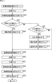
- step S ⁇ b> 11 the microphone array 31 collects the sound of the content in the sound collection space, and supplies the multi-channel sound collection signal s (i, nt ) obtained as a result to the time frequency analysis unit 32.
- step S ⁇ b> 12 the time frequency analysis unit 32 analyzes the time frequency information of the collected sound signal s (i, n t ) supplied from the microphone array 31.
- the time frequency analysis unit 32 performs time frequency conversion on the collected sound signal s (i, n t ), and supplies the time frequency spectrum S (i, n tf ) obtained as a result to the spatial frequency analysis unit 34. To do. For example, in the step S12, the calculation of the above formula (1) is performed.
- step S13 the direction correction unit 33 determines whether or not the rotation shake correction mode is set. That is, the direction correction unit 33 acquires correction mode information from the outside, and determines whether or not the direction correction mode indicated by the acquired correction mode information is the rotational shake correction mode.
- step S13 If it is determined in step S13 that the rotational shake correction mode is selected, the direction correction unit 33 calculates the correction angle ( ⁇ , ⁇ ) in step S14.
- the direction correction unit 33 acquires at least one of image information and sensor information, and obtains the rotation angle ( ⁇ , ⁇ ) of the microphone array 31 based on the acquired information.
- the direction correction unit 33 sets the obtained rotation angle ( ⁇ , ⁇ ) as the correction angle ( ⁇ , ⁇ ) as it is.
- the direction correction unit 33 acquires microphone arrangement information including angles ( ⁇ i , ⁇ i ) of each microphone unit, and performs spatial frequency analysis on the acquired microphone arrangement information and the obtained correction angles ( ⁇ , ⁇ ). The process proceeds to step S19.
- step S15 the direction correction unit 33 determines whether or not the direction correction mode indicated by the correction mode information is the shake correction mode. .
- step S16 the direction correction unit 33 acquires at least one of image information and sensor information, and the recording device 21, that is, the microphone array, based on the acquired information. 31 shakes are detected.
- the direction correcting unit 33 obtains the rotation angle ( ⁇ , ⁇ ) per unit time based on at least one of the image information and the sensor information, and the elevation angle and the azimuth according to the above formulas (3) and (5). For each corner, a shake is detected.
- step S17 the direction correction unit 33 calculates a correction angle ( ⁇ , ⁇ ) according to the shake detection result in step S16.
- the direction correction unit 33 satisfies the expression (3) and detects the shake in the elevation angle direction, the elevation angle ⁇ of the rotation angle ( ⁇ , ⁇ ) is directly used as the elevation angle of the correction angle ( ⁇ , ⁇ ).
- the correction angle ⁇ is set to 0 when no shake in the elevation angle direction is detected.
- the direction correction unit 33 uses the azimuth angle ⁇ of the rotation angle ( ⁇ , ⁇ ) as it is as the azimuth angle of the correction angle ( ⁇ , ⁇ ).
- the correction angle ⁇ is set to zero.
- step S18 the direction correcting unit 33 updates the reference direction ( ⁇ ref , ⁇ ref ) according to the shake detection result.
- the direction correction unit 33 if the elevation of the vibration is detected, and updates the elevation theta ref by the equation (4) described above, when the elevation direction of the blurring is not detected, it updates the elevation theta ref do not do.
- the direction correction unit 33 updates the azimuth angle ⁇ ref according to the above-described equation (6) when the azimuth direction blur is detected, and when the azimuth direction blur is not detected, the azimuth direction blur is detected. Do not update the angle ⁇ ref .
- the direction correction unit 33 acquires microphone arrangement information, and the acquired microphone arrangement information and the obtained correction angles ( ⁇ , ⁇ ) are spatially stored.
- the data is supplied to the frequency analysis unit 34, and the process proceeds to step S19.
- step S15 when it is determined in step S15 that the camera is not in the shake correction mode, that is, when the direction correction mode indicated by the correction mode information is the non-correction mode, the direction correction unit 33 corrects the correction angle as shown in Expression (7).
- Each angle of ( ⁇ , ⁇ ) is set to 0.
- the direction correcting unit 33 acquires the microphone arrangement information, supplies the acquired microphone arrangement information and the correction angle ( ⁇ , ⁇ ) to the spatial frequency analyzing unit 34, and the process proceeds to step S19.
- step S14 or step S18 If the process of step S14 or step S18 has been performed, or if it is determined that the camera is not in the shake correction mode in step S15, the spatial frequency analysis unit 34 performs spatial frequency conversion in step S19.
- the spatial frequency analysis unit 34 includes the microphone arrangement information and the correction angle ( ⁇ , ⁇ ) supplied from the direction correction unit 33 and the time frequency spectrum S (i, n) supplied from the time frequency analysis unit 32. Based on tf ), spatial frequency conversion is performed by calculating Equation (11) described above.
- the spatial frequency analysis unit 34 supplies the communication unit 35 with the spatial frequency spectrum S SP (n tf , n sf ) obtained by the spatial frequency conversion.
- step S20 the communication unit 35 transmits the spatial frequency spectrum S SP (n tf , n sf ) supplied from the spatial frequency analysis unit 34.
- step S ⁇ b > 21 the communication unit 41 receives the spatial frequency spectrum S SP (n tf , n sf ) transmitted by the communication unit 35 and supplies it to the spatial frequency synthesis unit 42.
- step S22 the spatial frequency synthesizing unit 42, based on the spatial frequency spectrum S SP (n tf , n sf ) supplied from the communication unit 41 and the speaker arrangement information supplied from the outside, the above equation (17 ) To perform spatial frequency inverse transform.
- the spatial frequency synthesizer 42 supplies the temporal frequency spectrum D (l, n tf ) obtained by the spatial frequency inverse transform to the temporal frequency synthesizer 43.
- step S23 the time-frequency synthesis unit 43 performs time-frequency synthesis on the time-frequency spectrum D (l, n tf ) supplied from the spatial frequency synthesis unit 42 by calculating the above equation (21). Then, the speaker drive signal d (l, n d ) is calculated.
- the time-frequency synthesizer 43 supplies the obtained speaker drive signal d (l, n d ) to each speaker unit constituting the speaker array 44.
- step S ⁇ b > 24 the speaker array 44 reproduces sound based on the speaker drive signal d (l, n d ) supplied from the time frequency synthesis unit 43. Thereby, the sound of the content, that is, the sound field of the sound collection space is reproduced.
- the recorded sound field direction controller 11 calculates the correction angle ( ⁇ , ⁇ ) according to the direction correction mode, and is corrected based on the correction angle ( ⁇ , ⁇ ) at the time of spatial frequency conversion.
- the spatial frequency spectrum S SP (n tf , n sf ) is calculated using the angle of each microphone unit.
- the direction of the recorded sound field can be fixed in a certain direction as needed, and more appropriately.
- the sound field can be reproduced.
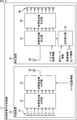
- the recorded sound field direction controller 11 is configured as shown in FIG. 8, for example.
- portions corresponding to those in FIG. 2 are denoted by the same reference numerals, and description thereof is omitted as appropriate.
- the configuration of the recorded sound field direction controller 11 shown in FIG. 8 differs from the configuration of the recorded sound field direction controller 11 shown in FIG. Then, it has the same structure as the recorded sound field direction controller 11 shown in FIG.
- the recording device 21 has a microphone array 31, a time frequency analysis unit 32, a spatial frequency analysis unit 34, and a communication unit 35.
- the playback device 22 includes a communication unit 41, a direction correction unit 33, a spatial frequency synthesis unit 42, a time frequency synthesis unit 43, and a speaker array 44.
- the direction correction unit 33 calculates the correction angle ( ⁇ , ⁇ ) by acquiring the correction mode information, the image information, and the sensor information as in the example shown in FIG. ⁇ , ⁇ ) is supplied to the spatial frequency synthesizer 42.
- the correction angle ( ⁇ , ⁇ ) is an angle for correcting an angle ( ⁇ l , ⁇ l ) indicating the direction of each speaker unit indicated by the speaker arrangement information.
- the image information and sensor information may be exchanged between the recording device 21 and the playback device 22 by the communication unit 35 and the communication unit 41 and supplied to the direction correction unit 33, or other methods. May be acquired by the direction correction unit 33.
- the spatial frequency analysis unit 34 acquires microphone arrangement information from the outside. Then, the spatial frequency analysis unit 34 calculates the above equation (11) based on the acquired microphone arrangement information and the time frequency spectrum S (i, n tf ) supplied from the time frequency analysis unit 32. Perform spatial frequency conversion.
- the spatial frequency analysis unit 34 uses the spherical harmonic function matrix Y mic represented by the following equation (22) obtained from the angle ( ⁇ i , ⁇ i ) of the microphone unit indicated by the microphone arrangement information. (11) is calculated.
- the spatial frequency analysis unit 34 calculates the spatial frequency conversion without correcting the microphone unit angles ( ⁇ i , ⁇ i ).
- the spatial frequency synthesis unit 42 calculates the following equation (23) based on the correction angles ( ⁇ , ⁇ ) supplied from the direction correction unit 33, and determines the direction of each speaker unit indicated by the speaker arrangement information.
- the indicated angle ( ⁇ 1 , ⁇ 1 ) is corrected.
- ⁇ l ′ and ⁇ l ′ are directions of each speaker unit after direction correction obtained by correcting the angle ( ⁇ l , ⁇ l ) with the correction angle ( ⁇ , ⁇ ). It is the angle which shows. That is, the elevation angle ⁇ l ′ is obtained by correcting the elevation angle ⁇ l by the correction angle ⁇ , and the azimuth angle ⁇ l ′ is obtained by correcting the azimuth angle ⁇ l by the correction angle ⁇ . is there.
- the spatial frequency synthesizer 42 obtains from the angle ( ⁇ l ′, ⁇ l ′), equation (17) described above with reference to spherical harmonics matrix Y SP shown in 24) calculates, performs spatial frequency inversion. That is, the spatial frequency inverse transform is performed using the spherical harmonic function matrix Y SP composed of the spherical harmonic functions obtained from the angle ( ⁇ l ′, ⁇ l ′) of the speaker unit after the direction correction.
- the spatial frequency synthesizing unit 42 corrects the angle indicating the direction of the speaker array 44 by the correction angle ( ⁇ , ⁇ ) at the time of inverse spatial frequency conversion, more specifically, the angle ( ⁇ l , ⁇ l ) of each speaker unit. Is done.
- the spatial frequency spectrum S SP is corrected by correcting the angle ( ⁇ l , ⁇ l ) indicating the direction of each speaker unit of the speaker array 44 in the spherical harmonic function used in the inverse spatial frequency conversion by the correction angle ( ⁇ , ⁇ ).
- (n tf , n sf ) is corrected appropriately. That is, a time-frequency spectrum D (l, n tf ) for reproducing a sound field in which rotation and shaking of the microphone array 31 are corrected can be obtained as appropriate by inverse spatial frequency conversion.
- the recorded sound field direction controller 11 shown in FIG. 8 reproduces the sound field by correcting the angle (direction) of the speaker unit, not the microphone unit.
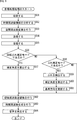
- step S51 and step S52 is the same as the process of step S11 and step S12 of FIG. 7, the description is abbreviate
- step S ⁇ b > 53 the spatial frequency analysis unit 34 performs spatial frequency conversion and supplies the spatial frequency spectrum S SP (n tf , n sf ) obtained as a result to the communication unit 35.
- the spatial frequency analysis unit 34 acquires microphone arrangement information, the spherical harmonic function matrix Y mic shown in Expression (22) obtained from the microphone arrangement information, and the time supplied from the time frequency analysis unit 32. Based on the frequency spectrum S (i, n tf ), spatial frequency conversion is performed by calculating Equation (11).
- step S54 and step S55 When the spatial frequency spectrum S SP (n tf , n sf ) is obtained by the spatial frequency conversion, the processing of step S54 and step S55 is performed thereafter, and the spatial frequency spectrum S SP (n tf , n sf ) is converted to the spatial frequency. It is supplied to the synthesis unit 42. Note that the processing in step S54 and step S55 is the same as the processing in step S20 and step S21 in FIG.
- step S55 When the process of step S55 is performed, the processes of step S56 to step S61 are performed thereafter, and the correction angle ( ⁇ for correcting the angle ( ⁇ 1 , ⁇ 1 ) of each speaker unit of the speaker array 44 is performed. , ⁇ ) is calculated. Note that the processing from step S56 to step S61 is the same as the processing from step S13 to step S18 in FIG.
- step S62 When the processing from step S56 to step S61 is performed to obtain the correction angle ( ⁇ , ⁇ ), the direction correction unit 33 supplies the obtained correction angle ( ⁇ , ⁇ ) to the spatial frequency synthesis unit 42, and then The process proceeds to step S62.
- step S ⁇ b> 62 the spatial frequency synthesis unit 42 acquires speaker arrangement information, the acquired speaker arrangement information, the correction angle ( ⁇ , ⁇ ) supplied from the direction correction unit 33, and the spatial frequency supplied from the communication unit 41. Spatial frequency inverse transform is performed based on the spectrum S SP (n tf , n sf ).
- the spatial frequency synthesis unit 42 calculates Expression (23) based on the speaker arrangement information and the correction angles ( ⁇ , ⁇ ), and obtains the spherical harmonic function matrix Y SP shown in Expression (24). Further, the spatial frequency synthesis unit 42 calculates Expression (17) based on the obtained spherical harmonic function matrix Y SP and the spatial frequency spectrum S SP (n tf , n sf ), and the time frequency spectrum D (l , n tf ).
- the spatial frequency synthesizer 42 supplies the temporal frequency spectrum D (l, n tf ) obtained by the spatial frequency inverse transform to the temporal frequency synthesizer 43.
- step S63 and step S64 are performed thereafter, and the sound field reproduction process is terminated.
- these processes are the same as the processes of step S23 and step S24 of FIG.
- the recorded sound field direction controller 11 calculates the correction angle ( ⁇ , ⁇ ) according to the direction correction mode, and is corrected based on the correction angle ( ⁇ , ⁇ ) at the time of spatial frequency reverse conversion.
- the time frequency spectrum D (l, n tf ) is calculated using the angle of each speaker unit.
- the direction of the recorded sound field can be fixed in a certain direction as needed, and more appropriately.
- the sound field can be reproduced.
- an annular microphone array or a spherical microphone array has been described as an example of the microphone array 31, but a linear microphone array may be used as the microphone array 31. Even in such a case, the sound field can be reproduced by the same processing as described above.
- the speaker array 44 is not limited to the annular speaker array or the spherical speaker array, and may be any type such as a linear speaker array.
- the series of processes described above can be executed by hardware or can be executed by software.
- a program constituting the software is installed in the computer.
- the computer includes, for example, a general-purpose computer capable of executing various functions by installing a computer incorporated in dedicated hardware and various programs.
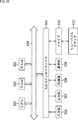
- FIG. 10 is a block diagram showing an example of the hardware configuration of a computer that executes the above-described series of processing by a program.
- a CPU Central Processing Unit
- ROM Read Only Memory
- RAM Random Access Memory
- An input / output interface 505 is further connected to the bus 504.
- An input unit 506, an output unit 507, a recording unit 508, a communication unit 509, and a drive 510 are connected to the input / output interface 505.
- the input unit 506 includes a keyboard, a mouse, a microphone, an image sensor, and the like.
- the output unit 507 includes a display, a speaker, and the like.
- the recording unit 508 includes a hard disk, a nonvolatile memory, and the like.
- the communication unit 509 includes a network interface or the like.
- the drive 510 drives a removable medium 511 such as a magnetic disk, an optical disk, a magneto-optical disk, or a semiconductor memory.
- the CPU 501 loads the program recorded in the recording unit 508 to the RAM 503 via the input / output interface 505 and the bus 504 and executes the program, for example. Is performed.
- the program executed by the computer (CPU 501) can be provided by being recorded in, for example, a removable medium 511 as a package medium or the like.
- the program can be provided via a wired or wireless transmission medium such as a local area network, the Internet, or digital satellite broadcasting.
- the program can be installed in the recording unit 508 via the input / output interface 505 by attaching the removable medium 511 to the drive 510. Further, the program can be received by the communication unit 509 via a wired or wireless transmission medium and installed in the recording unit 508. In addition, the program can be installed in advance in the ROM 502 or the recording unit 508.
- the program executed by the computer may be a program that is processed in time series in the order described in this specification, or in parallel or at a necessary timing such as when a call is made. It may be a program for processing.
- the present technology can take a cloud computing configuration in which one function is shared by a plurality of devices via a network and is jointly processed.
- each step described in the above flowchart can be executed by one device or can be shared by a plurality of devices.
- the plurality of processes included in the one step can be executed by being shared by a plurality of apparatuses in addition to being executed by one apparatus.
- the present technology can be configured as follows.
- a speech processing apparatus comprising: a correction unit that corrects a collected sound signal obtained by collecting sound with a microphone array based on direction information indicating a direction of the microphone array.
- the direction information is information indicating an angle of a direction of the microphone array from a predetermined reference direction.
- the correction unit corrects a spatial frequency spectrum obtained from the sound collection signal based on the direction information.
- the correction unit performs the correction at the time of spatial frequency conversion with respect to a temporal frequency spectrum obtained from the collected sound signal.
- the sound processing apparatus corrects the collected sound signal in accordance with displacement, angular velocity, or acceleration per unit time of the microphone array.
- the microphone array is an annular microphone array or a spherical microphone array.
- a sound processing method including a step of correcting a sound collection signal obtained by collecting sound with a microphone array based on direction information indicating a direction of the microphone array.
- a program that causes a computer to execute a process including a step of correcting a collected sound signal obtained by collecting sound with a microphone array based on direction information indicating the direction of the microphone array.
- 11 recording sound field direction controller 21 recording device, 22 playback device, 31 microphone array, 32 time frequency analysis unit, 33 direction correction unit, 34 spatial frequency analysis unit, 42 spatial frequency synthesis unit, 43 time frequency synthesis unit, 44 Speaker array
Landscapes
- Health & Medical Sciences (AREA)
- Otolaryngology (AREA)
- Physics & Mathematics (AREA)
- Engineering & Computer Science (AREA)
- Acoustics & Sound (AREA)
- Signal Processing (AREA)
- Circuit For Audible Band Transducer (AREA)
Abstract
本技術は、より適切に音場を再現することができるようにする音声処理装置および方法、並びにプログラムに関する。 マイクロホンアレイは、収音空間において音声を収音し、その結果得られた収音信号を出力する。時間周波数分析部は収音信号を時間周波数変換し、時間周波数スペクトルを得る。方向補正部は、補正モード情報と、画像情報またはセンサ情報とに基づいて、マイクロホンアレイの方向を補正するための補正角度を算出する。空間周波数分析部は、補正角度に基づいて時間周波数スペクトルに対する空間周波数変換を行うことで、マイクロホンアレイによる収音により得られた信号を補正する。本技術は音声処理装置に適用することができる。
Description
本技術は音声処理装置および方法、並びにプログラムに関し、特に、より適切に音場を再現することができるようにした音声処理装置および方法、並びにプログラムに関する。
従来、全方位の画像と音声(音場)を取得して、それらの画像と音声とからなるコンテンツを再生する技術が知られている。
このようなコンテンツに関する技術として、例えば広範囲の視野の画像を制御して視界の移動の平滑化を行うことで、全方位カメラにより得られた画像のぶれによる映像酔いや空間間隔のロストを防ぐ技術が提案されている(例えば、特許文献1参照)。
ところで、環状や球状のマイクロホンアレイを用いて全方位の音場を収録するときに、マイクロホンアレイが人などの移動する移動体に取り付けられることもある。そのような場合、移動体の動きによってマイクロホンアレイの方向に回転やぶれが生じるため、収録される音場も回転やぶれが含まれたものとなってしまう。
したがって、例えば収録したコンテンツについて、視聴者が自由な視点でコンテンツを視聴できる再生システムを考えた場合、マイクロホンアレイの方向に回転やぶれが生じると、視聴者がコンテンツを視聴している方向とは無関係にコンテンツの音場が回転してしまい、適切な音場を再現することができなくなってしまう。また、音場がぶれることにより、音酔いが生じてしまうこともある。
本技術は、このような状況に鑑みてなされたものであり、より適切に音場を再現することができるようにするものである。
本技術の一側面の音声処理装置は、マイクロホンアレイにより収音して得られた収音信号を、前記マイクロホンアレイの方向を示す方向情報に基づいて補正する補正部を備える。
前記方向情報を、所定の基準方向からの前記マイクロホンアレイの方向の角度を示す情報とすることができる。
前記補正部には、前記方向情報に基づいて、前記収音信号から得られた空間周波数スペクトルを補正させることができる。
前記補正部には、前記収音信号から得られた時間周波数スペクトルに対する空間周波数変換時に前記補正を行わせることができる。
前記補正部には、前記空間周波数変換に用いる球面調和関数における前記マイクロホンアレイの方向を示す角度を前記方向情報に基づいて補正させることができる。
前記補正部には、前記収音信号から得られた空間周波数スペクトルに対する空間周波数逆変換時に前記補正を行わせることができる。
前記補正部には、前記空間周波数逆変換に用いる球面調和関数における、前記収音信号に基づく音声を再生するスピーカアレイの方向を示す角度を前記方向情報に基づいて補正させることができる。
前記補正部には、前記マイクロホンアレイの単位時間当たりの変位、角速度、または加速度に応じて前記収音信号を補正させることができる。
前記マイクロホンアレイを、環状マイクロホンアレイまたは球状マイクロホンアレイとすることができる。
本技術の一側面の音声処理方法またはプログラムは、マイクロホンアレイにより収音して得られた収音信号を、前記マイクロホンアレイの方向を示す方向情報に基づいて補正するステップを含む。
本技術の一側面においては、マイクロホンアレイにより収音して得られた収音信号が、前記マイクロホンアレイの方向を示す方向情報に基づいて補正される。
本技術の一側面によれば、より適切に音場を再現することができる。
なお、ここに記載された効果は必ずしも限定されるものではなく、本開示中に記載された何れかの効果であってもよい。
以下、図面を参照して、本技術を適用した実施の形態について説明する。
〈第1の実施の形態〉
〈本技術について〉
本技術は、収音空間において複数のマイクロホンからなるマイクロホンアレイにより音場を収録し、その結果得られたマルチチャンネルの収音信号に基づいて、再生空間に配置された複数のスピーカからなるスピーカアレイにより音場を再現するものである。
〈本技術について〉
本技術は、収音空間において複数のマイクロホンからなるマイクロホンアレイにより音場を収録し、その結果得られたマルチチャンネルの収音信号に基づいて、再生空間に配置された複数のスピーカからなるスピーカアレイにより音場を再現するものである。
なお、マイクロホンアレイは、複数のマイクロホンが環状に配置された環状マイクロホンアレイや、複数のマイクロホンが球状に配置された球状マイクロホンアレイなど、複数のマイクロホンが並べられて構成されたものであれば、どのようなものであってもよい。同様に、スピーカアレイも複数のスピーカが環状に配置されたものや、複数のスピーカが球状に配置されたものなど、複数のスピーカが並べられて構成されたものであれば、どのようなものであってもよい。
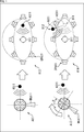
例えば図1の矢印A11に示すように、所定の基準となる方向に向けられて配置されているマイクロホンアレイMKA11により音源AS11から出力された音声を収音するとする。すなわち、マイクロホンアレイMKA11が配置された収音空間の音場が収録されるとする。
そして、矢印A12に示すように再生空間において、マイクロホンアレイMKA11による収音によって得られた収音信号に基づいて、複数のスピーカからなるスピーカアレイSPA11が音声を再生するとする。すなわち、スピーカアレイSPA11により音場が再現されるとする。
この例では、スピーカアレイSPA11を構成する各スピーカにより囲まれる位置に視聴者、つまり音声の聴取者であるユーザU11が位置しており、音声の再生時には、ユーザU11には、そのユーザU11から見て右方向から音源AS11からの音声が聞こえてくる。そのため、この例では音場が適切に再現されていることが分かる。
これに対して、矢印A13に示すようにマイクロホンアレイMKA11が、上述した基準方向に対して角度θだけ傾いている状態で、音源AS11から出力された音声を収音したとする。
この場合、収音によって得られた収音信号に基づいて、再生空間においてスピーカアレイSPA11により音声を再生すると、矢印A14に示すように適切に音場を再現することができなくなってしまう。
この例では、本来、矢印B11に示す位置に定位すべきである音源AS11の音像が、マイクロホンアレイMKA11の傾きの分だけ、つまり角度θだけ回転移動してしまい、矢印B12に示す位置に定位してしまう。
このようにマイクロホンアレイMKA11が基準となる状態から回転してしまった場合や、マイクロホンアレイMKA11にぶれが生じてしまった場合には、収音信号に基づいて再現される音場にも回転やぶれが生じてしまう。
そこで、本技術では、音場の収録時にマイクロホンアレイの方向を示す方向情報を利用することによって収録音場の回転やぶれを補正するようにした。
これにより、音場の収録時にマイクロホンアレイが回転したりぶれたりした場合であっても、収録音場の方向を一定方向に固定することができ、より適切に音場を再現することができるようになる。
例えば、音場収録時におけるマイクロホンアレイの方向を示す方向情報を取得する方法としては、マイクロホンアレイにジャイロセンサや加速度センサを設ける方法が考えられる。
その他、例えば全方位または一部の方向を撮影可能なカメラデバイスと、マイクロホンアレイとを一体化したデバイスを用いるようにし、カメラデバイスによる撮影により得られた画像情報、すなわち撮影された画像に基づいてマイクロホンアレイの方向を算出するようにしてもよい。
さらに、少なくとも音声を含むコンテンツの再生システムとしては、マイクロホンアレイが取り付けられた移動体の視点とは無関係にコンテンツの音場を再現する方法と、マイクロホンアレイが取り付けられた移動体の視点でコンテンツの音場を再現する方法とが考えられる。
例えば移動体の視点とは無関係に音場を再現する場合には、音場の方向の補正、つまり上述した回転の補正を行うようにし、移動体の視点で音場を再現する場合には音場の方向の補正を行わないようにすることで、適切な音場再現を実現することができる。
以上のように本技術によれば、マイクロホンアレイの方向に関わらず、必要に応じて収録音場を一定方向に固定することが可能となる。これにより、視聴者が自由な視点で収録コンテンツを視聴できる再生システムにおいて、より適切に音場を再現することができる。さらに、本技術によれば、マイクロホンアレイのぶれにより生じる音場のぶれも補正することができる。
〈収録音場方向制御器の構成例〉
次に、本技術を収録音場方向制御器に適用した場合を例として、本技術を適用した実施の形態について説明する。
次に、本技術を収録音場方向制御器に適用した場合を例として、本技術を適用した実施の形態について説明する。
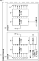
図2は、本技術を適用した収録音場方向制御器の一実施の形態の構成例を示す図である。
図2に示す収録音場方向制御器11は、収音空間に配置された収録装置21と、再生空間に配置された再生装置22とを有している。
収録装置21は、収音空間の音場を収録し、その結果得られた信号を再生装置22へと供給し、再生装置22は、収録装置21から信号の供給を受けて、その信号に基づいて収音空間の音場を再現する。
収録装置21は、マイクロホンアレイ31、時間周波数分析部32、方向補正部33、空間周波数分析部34、および通信部35を備えている。
マイクロホンアレイ31は、例えば環状マイクロホンアレイや球状マイクロホンアレイからなり、収音空間の音声をコンテンツとして収音して、その結果得られたマルチチャンネルの音声信号である収音信号を時間周波数分析部32に供給する。
時間周波数分析部32は、マイクロホンアレイ31から供給された収音信号に対して時間周波数変換を行い、その結果得られた時間周波数スペクトルを空間周波数分析部34に供給する。
方向補正部33は、補正モード情報、マイク配置情報、画像情報、およびセンサ情報のうちの一部または全部を必要に応じて取得し、取得した情報に基づいて収録装置21の方向を補正するための補正角度を算出する。方向補正部33は、マイク配置情報と補正角度とを空間周波数分析部34に供給する。
なお、補正モード情報は、収録音場の方向、すなわち収録装置21の方向を補正する方向補正モードとして、どのモードが指定されているかを示す情報である。
ここでは、例えば方向補正モードには回転ぶれ補正モード、ぶれ補正モード、および補正無しモードの3種類があるものとする。
回転ぶれ補正モードは収録装置21の回転とぶれを補正するモードであり、例えば回転ぶれ補正モードは、収録音場を一定方向に固定したままでのコンテンツの再生、つまり音場の再現を行う場合に選択される。
ぶれ補正モードは収録装置21のぶれのみを補正するモードであり、例えばぶれ補正モードは、収録装置21が取り付けられた移動体の視点でのコンテンツの再生、つまり音場の再現を行う場合に選択される。補正無しモードは、収録装置21の回転もぶれも補正しないモードである。
また、マイク配置情報は収録装置21、つまりマイクロホンアレイ31の予め定められた基準となる方向を示す角度情報である。
このマイク配置情報は、例えば収録装置21により音場の収録、つまり音声の収音を開始した時点など、所定時刻(以下、基準時刻とも称する)におけるマイクロホンアレイ31の方向、より詳細にはマイクロホンアレイ31を構成する各マイクロホンの方向を示す情報である。したがって、この場合、例えば収録装置21が音場の収録時に静止したままの状態であれば、収録中におけるマイクロホンアレイ31の各マイクロホンの方向は、マイク配置情報により示される方向のままとなる。
さらに、画像情報は、例えば収録装置21に、マイクロホンアレイ31と一体的に設けられた図示せぬカメラデバイスにより撮影された画像である。センサ情報は、例えば収録装置21に、マイクロホンアレイ31と一体的に設けられた図示せぬジャイロセンサにより得られた収録装置21、つまりマイクロホンアレイ31の回転量(変位)を示す情報である。
空間周波数分析部34は、方向補正部33から供給されたマイク配置情報および補正角度を用いて、時間周波数分析部32から供給された時間周波数スペクトルに対して空間周波数変換を行い、その結果得られた空間周波数スペクトルを通信部35に供給する。
通信部35は、空間周波数分析部34から供給された空間周波数スペクトルを、有線または無線により再生装置22に送信する。
また、再生装置22は、通信部41、空間周波数合成部42、時間周波数合成部43、およびスピーカアレイ44を備えている。
通信部41は、収録装置21の通信部35から送信されてきた空間周波数スペクトルを受信して空間周波数合成部42に供給する。
空間周波数合成部42は、外部から供給されたスピーカ配置情報に基づいて、通信部41から供給された空間周波数スペクトルを空間周波数合成し、その結果得られた時間周波数スペクトルを時間周波数合成部43に供給する。
ここで、スピーカ配置情報は、スピーカアレイ44の方向、より詳細にはスピーカアレイ44を構成する各スピーカの方向を示す角度情報である。
時間周波数合成部43は、空間周波数合成部42から供給された時間周波数スペクトルを時間周波数合成し、その結果得られた時間信号をスピーカ駆動信号としてスピーカアレイ44に供給する。
スピーカアレイ44は、複数のスピーカから構成される環状スピーカアレイや球状スピーカアレイなどからなり、時間周波数合成部43から供給されたスピーカ駆動信号に基づいて音声を再生する。
続いて、収録音場方向制御器11を構成する各部についてより詳細に説明する。
(時間周波数分析部)
時間周波数分析部32は、マイクロホンアレイ31を構成する各マイクロホン(以下、マイクユニットとも称することとする)が音声を収音することで得られたマルチチャンネルの収音信号s(i,nt)を、次式(1)の計算を行うことで、DFT(Discrete Fourier Transform)(離散フーリエ変換)を用いて時間周波数変換し、時間周波数スペクトルS(i,ntf)を求める。
時間周波数分析部32は、マイクロホンアレイ31を構成する各マイクロホン(以下、マイクユニットとも称することとする)が音声を収音することで得られたマルチチャンネルの収音信号s(i,nt)を、次式(1)の計算を行うことで、DFT(Discrete Fourier Transform)(離散フーリエ変換)を用いて時間周波数変換し、時間周波数スペクトルS(i,ntf)を求める。

なお、式(1)において、iは、マイクロホンアレイ31を構成するマイクユニットを特定するマイクロホンインデックスを示しており、マイクロホンインデックスi=0,1,2,…,I-1である。また、Iはマイクロホンアレイ31を構成するマイクユニットの数を示しており、ntは時間インデックスを示している。
さらに式(1)において、ntfは時間周波数インデックスを示しており、MtはDFTのサンプル数を示しており、jは純虚数を示している。
時間周波数分析部32は、時間周波数変換により得られた時間周波数スペクトルS(i,ntf)を空間周波数分析部34に供給する。
(方向補正部)
方向補正部33は、補正モード情報、マイク配置情報、画像情報、およびセンサ情報を取得し、取得した情報に基づいて収録装置21の方向、つまりマイク配置情報を補正するための補正角度を算出して、マイク配置情報と補正角度を空間周波数分析部34に供給する。
方向補正部33は、補正モード情報、マイク配置情報、画像情報、およびセンサ情報を取得し、取得した情報に基づいて収録装置21の方向、つまりマイク配置情報を補正するための補正角度を算出して、マイク配置情報と補正角度を空間周波数分析部34に供給する。
例えばマイク配置情報により示されるマイクロホンアレイ31の各マイクユニットの方向を示す角度情報、画像情報やセンサ情報から得られる所定時刻におけるマイクロホンアレイ31の方向を示す角度情報などの各角度情報は、方位角と仰角により表される。
すなわち、例えば図3に示すように原点Oを基準とし、x軸、y軸、およびz軸を各軸とする3次元座標系を考えるとする。
いま、所定のマイクロホンアレイ31を構成するマイクユニットMU11と原点Oとを結ぶ直線を直線LNとし、直線LNをz軸方向からxy平面に投影して得られる直線を直線LN’とする。
このとき、x軸と直線LN’とのなす角度φが、xy平面における原点Oから見たマイクユニットMU11の方向を示す方位角とされる。また、xy平面と直線LNとのなす角度θが、xy平面と垂直な平面における原点Oから見たマイクユニットMU11の方向を示す仰角とされる。
以下においては、基準時刻におけるマイクロホンアレイ31の方向、つまり所定の基準となるマイクロホンアレイ31の方向を基準方向とし、各角度情報は基準方向からの方位角および仰角により表されるものとする。また、基準方向は、仰角θrefおよび方位角φrefにより表されるものとし、以下では基準方向(θref,φref)とも記すこととする。
マイク配置情報は、マイクロホンアレイ31を構成する各マイクユニットの基準となる方向、つまり基準時刻における各マイクユニットの方向を示す情報からなる。
より具体的には、例えばマイクロホンインデックスがiであるマイクユニットの方向を示す情報は、基準時刻における、基準方向(θref,φref)に対するそのマイクユニットの相対的な方向を示す角度(θi,φi)とされる。ここで、θiは基準方向(θref,φref)から見たマイクユニットの方向の仰角であり、φiは基準方向(θref,φref)から見たマイクユニットの方向の方位角である。
したがって、例えば図3に示した例においてx軸方向が基準方向(θref,φref)であるときには、マイクユニットMU11の角度(θi,φi)は仰角θi=θおよび方位角φi=φとなる。
また、方向補正部33では、画像情報およびセンサ情報の少なくとも何れか一方に基づいて、基準時刻とは異なる音場の収録時の所定時刻(以下、処理対象時刻とも称する)における基準方向(θref,φref)からのマイクロホンアレイ31の回転角度(θ,φ)を求める。
ここで、回転角度(θ,φ)は、処理対象時刻における基準方向(θref,φref)に対するマイクロホンアレイ31の相対的な方向を示す角度情報である。
すなわち、回転角度(θ,φ)を構成する仰角θは基準方向(θref,φref)から見たマイクロホンアレイ31の方向の仰角であり、回転角度(θ,φ)を構成する方位角φは基準方向(θref,φref)から見たマイクロホンアレイ31の方向の方位角である。
例えば方向補正部33は、処理対象時刻にカメラデバイスにより撮影された画像を画像情報として取得し、その画像情報に基づいて画像認識等によりマイクロホンアレイ31、すなわち収録装置21の基準方向からの変位を検出することで回転角度(θ,φ)を算出する。換言すれば、方向補正部33は、収録装置21の基準方向からの回転方向および回転量を検出することで回転角度(θ,φ)を算出する。
また、例えば方向補正部33は、処理対象時刻にジャイロセンサにより出力された角速度、つまり単位時間当たりの回転角を示す情報をセンサ情報として取得し、必要に応じて取得したセンサ情報に基づく積分演算等を行うことにより回転角度(θ,φ)を算出する。
なお、ここではジャイロセンサ(角速度センサ)から得られたセンサ情報に基づいて回転角度(θ,φ)を算出する例について説明した。しかし、その他、加速度センサの出力である加速度、つまり単位時間当たりの速度変化をセンサ情報として取得し、回転角度(θ,φ)を算出するようにしてもよい。
以上のようにして得られる回転角度(θ,φ)が、処理対象時刻における基準方向(θref,φref)からのマイクロホンアレイ31の方向の角度を示す方向情報である。
さらに、方向補正部33は、補正モード情報および回転角度(θ,φ)に基づいてマイク配置情報、すなわち各マイクユニットの角度(θi,φi)を補正するための補正角度(α,β)を算出する。
ここで、補正角度(α,β)のαは、マイクユニットの角度(θi,φi)の仰角θiの補正角度であり、補正角度(α,β)のβは、マイクユニットの角度(θi,φi)の方位角φiの補正角度である。
方向補正部33は、このようにして得られた補正角度(α,β)と、マイク配置情報である各マイクユニットの角度(θi,φi)とを空間周波数分析部34に出力する。
例えば、補正モード情報により示される方向補正モードが回転ぶれ補正モードである場合、方向補正部33は、次式(2)に示すように回転角度(θ,φ)をそのまま補正角度(α,β)とする。
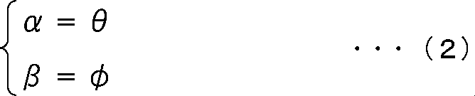
式(2)では、回転角度(θ,φ)がそのまま補正角度(α,β)とされている。これは、空間周波数分析部34において、マイクユニットの角度(θi,φi)をそのマイクユニットが回転した分だけ、つまり補正角度(α,β)の分だけ補正すれば、マイクユニットの回転とぶれを補正することができるからである。すなわち、時間周波数スペクトルS(i,ntf)に含まれていたマイクユニットの回転とぶれが補正され、適切な空間周波数スペクトルを得ることができるためである。
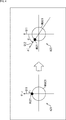
具体的には、例えば図4に示すようにマイクロホンアレイ31としての環状マイクロホンアレイMKA21を構成するマイクユニットMU21の方位角に注目するとする。
例えば矢印A21に示すように矢印Q11に示す方向が基準方向(θref,φref)の方位角φrefの方向であり、マイクユニットMU21の基準となる方位角の方向も矢印Q11に示す方向であったとする。この場合、マイクユニットの角度(θi,φi)を構成する方位角φiは、方位角φi=0となる。
このような状態から矢印A22に示すように環状マイクロホンアレイMKA21が回転し、処理対象時刻において、マイクユニットMU21の方位角の方向が矢印Q12に示す方向となったとする。この例では、マイクユニットMU21の方向は、方位角の方向に角度φだけ変化している。この角度φは、回転角度(θ,φ)を構成する方位角φである。
したがって、この例では上述した式(2)により、マイクユニットMU21の方位角が変化した分の角度φが補正角度βとされる。
ここで、補正角度(α,β)によるマイクユニットの角度(θi,φi)の補正後の角度を(θi’,φi’)とすると、方向補正後のマイクユニットMU21の角度(θi’,φi’)の方位角は、φi’=0+φ=φとなる。
回転ぶれ補正モードでは、基準方向(θref,φref)から見た処理対象時刻における各マイクユニットの方向を示す角度が、補正後のマイクユニットの角度(θi’,φi’)とされる。
また、補正モード情報により示される方向補正モードがぶれ補正モードである場合、方向補正部33は、マイクロホンアレイ31、つまり各マイクユニットについて、方位角方向および仰角方向の方向ごとに、ぶれが発生したかを検出する。例えばぶれの検出は、単位時間あたりのマイクユニット、すなわち収録装置21の回転角度(変化量)が、予め定めたぶれの範囲を表す閾値を超えたか否かを判定することにより行われる。
具体的には、例えば方向補正部33はマイクロホンアレイ31の回転角度(θ,φ)を構成する仰角θと予め定められた閾値θthresとを比較し、次式(3)が満たされる場合、つまり仰角方向の回転量が閾値θthres未満である場合、仰角方向にぶれが発生したと判定する。

すなわち、画像情報やセンサ情報から得られる、収録装置21の単位時間当たりの変位、角速度、加速度等から算出される、単位時間当たりの収録装置21の仰角方向の回転角である仰角θの絶対値が閾値θthres未満である場合、収録装置21の仰角方向の動きはぶれであると判定される。
方向補正部33は、仰角方向にぶれが発生したと判定された場合、仰角方向について、上述した式(2)に示したように回転角度(θ,φ)の仰角θを、そのまま補正角度(α,β)の仰角の補正角度αとして用いる。
これに対して、方向補正部33は、仰角方向にぶれが発生していないと判定された場合、補正角度(α,β)の仰角の補正角度αを、補正角度α=0とする。
さらに、仰角方向にぶれが発生していないと判定された場合、方向補正部33は次式(4)により基準方向(θref,φref)の仰角θrefを更新(補正)する。

なお、式(4)において、仰角θref’は更新前の仰角θrefを示している。したがって、式(4)の計算では、更新前の仰角θref’に、マイクロホンアレイ31の回転角度(θ,φ)を構成する仰角θが加算されて、更新後の新たな仰角θrefとされている。
これは、ぶれ補正モードでは、マイクロホンアレイ31のぶれのみが補正され、マイクロホンアレイ31の回転は補正されないため、基準方向(θref,φref)を更新しないとマイクロホンアレイ31が回転したときに、正しくぶれを検出できなくなるからである。
例えば式(3)が満たされない場合、つまり|θ|≧θthresである場合、マイクロホンアレイ31の回転量が大きいので、マイクロホンアレイ31の動きはぶれではなく意図的な回転であるとされる。この場合、マイクロホンアレイ31の回転に合わせて、その回転の分だけ基準方向(θref,φref)も回転させることで、次の処理対象時刻において、更新された新たな基準方向(θref,φref)と回転角度(θ,φ)とから、式(3)によりマイクロホンアレイ31のぶれを検出することができる。
また、補正モード情報により示される方向補正モードがぶれ補正モードである場合、方向補正部33は、仰角方向と同様にして方位角方向についても補正角度(α,β)の方位角の補正角度βを求める。
すなわち、例えば方向補正部33はマイクロホンアレイ31の回転角度(θ,φ)を構成する方位角φと予め定められた閾値φthresとを比較し、次式(5)が満たされる場合、つまり方位角方向の回転量が閾値φthres未満である場合、方位角方向にぶれが発生したと判定する。

方向補正部33は、方位角方向にぶれが発生したと判定された場合、方位角方向について、上述した式(2)に示したように回転角度(θ,φ)の方位角φを、そのまま補正角度(α,β)の方位角の補正角度βとして用いる。
これに対して、方向補正部33は、方位角方向にぶれが発生していないと判定された場合、補正角度(α,β)の方位角の補正角度βを、補正角度β=0とする。
さらに、方位角方向にぶれが発生していないと判定された場合、方向補正部33は次式(6)により基準方向(θref,φref)の方位角φrefを更新(補正)する。

なお、式(6)において、方位角φref’は更新前の方位角φrefを示している。したがって、式(6)の計算では、更新前の方位角φref’に、マイクロホンアレイ31の回転角度(θ,φ)を構成する方位角φが加算されて、更新後の新たな方位角φrefとされている。
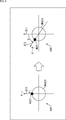
具体的には、例えば図5に示すようにマイクロホンアレイ31としての環状マイクロホンアレイMKA21を構成するマイクユニットMU21の方位角に注目するとする。なお、図5において、図4における場合と対応する部分には同一の符号を付してあり、その説明は適宜省略する。
例えば矢印A31に示すように矢印Q11に示す方向が基準方向(θref,φref)の方位角φrefの方向であり、マイクユニットMU21の基準となる方位角の方向も矢印Q11に示す方向であったとする。
また、矢印Q21に示す方向の直線と、矢印Q11に示す方向の直線とのなす角度が閾値φthresの角度であり、同様に矢印Q22に示す方向の直線と、矢印Q11に示す方向の直線とのなす角度が閾値φthresの角度であるとする。
この場合、処理対象時刻におけるマイクユニットMU21の方位角の方向が、矢印Q21に示す方向と、矢印Q22に示す方向との間の方向であれば、マイクユニットMU21の方位角方向への回転量は十分に小さいため、マイクユニットMU21の動きはぶれによるものであるということができる。
例えば、矢印A32に示すように、処理対象時刻におけるマイクユニットMU21の方位角の方向が基準方向から角度φだけ変化し、矢印Q23に示す方向となったとする。
この場合、矢印Q23に示す方向は、矢印Q21に示す方向と、矢印Q22に示す方向との間の方向であり、上述した式(5)が成立する。したがって、この場合におけるマイクユニットMU21の動きはぶれによるものとされ、上述した式(2)によりマイクユニットMU21の方位角の補正角度βが求められる。
これに対して、例えば矢印A33に示すように、処理対象時刻におけるマイクユニットMU21の方位角の方向が基準方向から角度φだけ変化し、矢印Q24に示す方向となったとする。
この場合、矢印Q24に示す方向は、矢印Q21に示す方向と、矢印Q22に示す方向との間の方向ではなく、上述した式(5)が成立しない。すなわち、マイクユニットMU21が方位角方向に閾値φthresにより示される角度以上移動している。
したがって、この場合におけるマイクユニットMU21の動きは回転によるものとされて、マイクユニットMU21の方位角の補正角度βは0とされる。この場合、空間周波数分析部34において、方向補正後のマイクユニットMU21の角度(θi’,φi’)の方位角φi’はφiのままとされる。
また、この場合、上述した式(6)により基準方向(θref,φref)の方位角φrefが更新される。この例では、更新前の基準方向(θref,φref)の方位角φrefの方向は、回転移動前のマイクユニットMU21の方位角の方向、つまり矢印Q11に示す方向であったので、回転移動後のマイクユニットMU21の方位角の方向、つまり矢印Q24に示す方向が更新後の方位角φrefの方向とされる。
そして、次の処理対象時刻では、矢印Q24に示す方向が新たな方位角φrefの方向とされて、矢印Q24に示す方向からのマイクユニットMU21の方位角の変化量に基づいて、マイクユニットMU21の方位角方向のぶれが検出される。
このように方向補正部33では、方位角方向と仰角方向とで、それぞれ独立にぶれが検出され、マイクユニットの補正角度が求められる。
方向補正部33において、ぶれの検出結果に基づいて補正角度(α,β)が算出されるので、空間周波数分析部34では、画像情報やセンサ情報から得られる、収録装置21の単位時間当たりの変位、角速度、加速度等に応じて、空間周波数変換時における空間周波数スペクトルの補正が行われることになる。この空間周波数スペクトルの補正は、補正角度(α,β)によりマイクユニットの角度(θi,φi)を補正することにより実現される。
特に、ぶれ補正モードでは、ぶれの検出を行うことで、ぶれと、収録装置21の回転とを分離(区別)して、ぶれのみを補正することができる。これにより、より適切に音場を再現することができるようになる。
なお、収録装置21のぶれ、つまりマイクユニットのぶれの検出は、上述した例に限らず、他のどのような方法により行われてもよい。
さらに、例えば補正モード情報により示される方向補正モードが補正無しモードである場合、方向補正部33は、次式(7)に示すように補正角度(α,β)を構成する仰角の補正角度αおよび方位角の補正角度βをともに0とする。

この場合、マイクユニットの角度(θi,φi)が、そのまま補正後の各マイクユニットの角度(θi’,φi’)とされることになる。すなわち、補正無しモードでは、各マイクユニットの角度(θi,φi)の補正は行われない。
具体的には、例えば図6に示すようにマイクロホンアレイ31としての環状マイクロホンアレイMKA21を構成するマイクユニットMU21の方位角に注目するとする。なお、図6において、図4における場合と対応する部分には同一の符号を付してあり、その説明は適宜省略する。
例えば矢印A41に示すように矢印Q11に示す方向が基準方向(θref,φref)の方位角φrefの方向であり、基準となるマイクユニットMU21の方位角の方向も矢印Q11に示す方向であったとする。
このような状態から矢印A42に示すように環状マイクロホンアレイMKA21が回転し、処理対象時刻において、マイクユニットMU21の方位角の方向が矢印Q12に示す方向となったとする。この例では、マイクユニットMU21の方向は、方位角の方向に角度φだけ変化している。
補正無しモードでは、このようにマイクユニットMU21の方向が変化した場合でも、補正角度(α,β)はα=0、β=0とされ、各マイクユニットの角度(θi,φi)の補正は行われない。すなわち、マイク配置情報により示されるマイクユニットMU21の角度(θi,φi)が、そのまま補正後の各マイクユニットの角度(θi’,φi’)とされる。
(空間周波数分析部)
空間周波数分析部34は、方向補正部33から供給されたマイク配置情報および補正角度(α,β)を用いて、時間周波数分析部32から供給された時間周波数スペクトルS(i,ntf)に対して空間周波数変換を行う。
空間周波数分析部34は、方向補正部33から供給されたマイク配置情報および補正角度(α,β)を用いて、時間周波数分析部32から供給された時間周波数スペクトルS(i,ntf)に対して空間周波数変換を行う。
例えば空間周波数変換では、球面調和級数展開が用いられて時間周波数スペクトルS(i,ntf)が空間周波数スペクトルSSP(ntf,nsf)に変換される。なお、空間周波数スペクトルSSP(ntf,nsf)におけるntfは時間周波数インデックスを示しており、nsfは空間周波数インデックスを示している。
一般的に、ある球上の音場Pは次式(8)に示すように表すことができる。

なお、式(8)において、Yは球面調和関数行列を示しており、Wは球の半径および空間周波数の次数による重み係数を示しており、Bは空間周波数スペクトルを示している。このような式(8)の計算は空間周波数逆変換に相当する。
したがって、次式(9)を計算することで空間周波数スペクトルBを求めることができる。この式(9)の計算は空間周波数変換に相当する。

なお、式(9)においてY+は球面調和関数行列Yの疑似逆行列を示しており、球面調和関数行列Yの転置行列をYTとして次式(10)により得られるものである。

以上のことから次式(11)により空間周波数スペクトルSSP(ntf,nsf)が得られることが分かる。空間周波数分析部34は、式(11)を計算して空間周波数変換を行うことで、空間周波数スペクトルSSP(ntf,nsf)を求める。

なお、式(11)において、SSPは各空間周波数スペクトルSSP(ntf,nsf)からなるベクトルを示しており、ベクトルSSPは以下の式(12)により表される。また、式(11)において、Sは各時間周波数スペクトルS(i,ntf)からなるベクトルを示しており、ベクトルSは以下の式(13)により表される。
さらに、式(11)において、Ymicは球面調和関数行列を示しており、球面調和関数行列Ymicは以下の式(14)により表される。また、式(11)において、Ymic
Tは球面調和関数行列Ymicの転置行列を示している。
ここで、式(11)において、ベクトルSSP、ベクトルS、および球面調和関数行列Ymicは、式(9)における空間周波数スペクトルB、音場P、および球面調和関数行列Yに対応する。また、式(11)においては、式(9)に示した重み係数Wに対応する重み係数については省略されている。
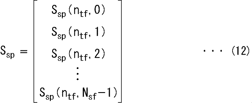
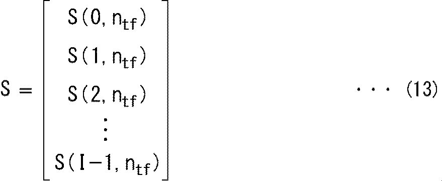
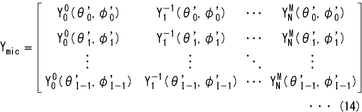
また、式(12)におけるNsfは、後述する球面調和関数の次数の最大値により定まる値を示しており、空間周波数インデックスnsf=0,1,…,Nsf-1である。
さらに、式(14)におけるYn
m(θ,φ)は次式(15)に示す球面調和関数である。

式(15)において、nおよびmは球面調和関数Yn
m(θ,φ)の次数を示しており、jは純虚数を示しており、ωは角周波数を示している。また、次数nの最大値、つまり最大次数はn=Nであり、式(12)におけるNsfはNsf=(N+1)2である。
さらに、式(14)の球面調和関数におけるθi’およびφi’は、マイク配置情報により示されるマイクユニットの角度(θi,φi)を構成する仰角θiおよび方位角φiの補正角度(α,β)による補正後の仰角および方位角を示している。方向補正後のマイクユニットの角度(θi’,φi’)は、次式(16)により示される角度となる。

このように空間周波数分析部34では、空間周波数変換時に補正角度(α,β)によりマイクロホンアレイ31の方向を示す角度、より詳細には各マイクユニットの角度(θi,φi)が補正される。
補正角度(α,β)により空間周波数変換で用いられる球面調和関数における、マイクロホンアレイ31の各マイクユニットの方向を示す角度(θi,φi)を補正することで、空間周波数スペクトルSSP(ntf,nsf)が適切に補正される。すなわち、適宜、マイクロホンアレイ31の回転やぶれが補正された音場を再現するための空間周波数スペクトルSSP(ntf,nsf)を得ることができる。
以上の計算により空間周波数スペクトルSSP(ntf,nsf)が得られると、空間周波数分析部34は、空間周波数スペクトルSSP(ntf,nsf)を、通信部35および通信部41を介して空間周波数合成部42に供給する。
なお、空間周波数変換により空間周波数スペクトルを求める方法については、例えば「Jerome Daniel, Rozenn Nicol, Sebastien Moreau, “Further Investigations of High Order Ambisonics and Wavefield Synthesis for Holophonic Sound Imaging,” AES 114th Convention, Amsterdam, Netherlands, 2003」などに詳細に記載されている。
(空間周波数合成部)
空間周波数合成部42は、空間周波数分析部34で得られた空間周波数スペクトルSSP(ntf,nsf)に対して、スピーカアレイ44を構成する各スピーカの方向を示す角度による球面調和関数行列を用いて空間周波数逆変換を行い、時間周波数スペクトルを求める。すなわち、空間周波数合成として空間周波数逆変換が行われる。
空間周波数合成部42は、空間周波数分析部34で得られた空間周波数スペクトルSSP(ntf,nsf)に対して、スピーカアレイ44を構成する各スピーカの方向を示す角度による球面調和関数行列を用いて空間周波数逆変換を行い、時間周波数スペクトルを求める。すなわち、空間周波数合成として空間周波数逆変換が行われる。
なお、以下、スピーカアレイ44を構成する各スピーカをスピーカユニットとも称することとする。ここで、スピーカアレイ44を構成するスピーカユニットの数をスピーカユニット数Lとし、各スピーカユニットを示すスピーカユニットインデックスをlとする。この場合、スピーカユニットインデックスl=0,1,…,L-1である。
いま、外部から空間周波数合成部42に供給されるスピーカ配置情報が、スピーカユニットインデックスlにより示される各スピーカユニットの方向を示す角度(ξl,ψl)であるとする。
ここで、スピーカユニットの角度(ξl,ψl)を構成するξlおよびψlは、それぞれ上述した仰角θiおよび方位角φiに対応する、スピーカユニットの仰角および方位角を示す角度であり、所定の基準方向からの角度である。
空間周波数合成部42は、スピーカユニットインデックスlにより示されるスピーカユニットの方向を示す角度(ξl,ψl)について得られる球面調和関数Yn
m(ξl,ψl)と、空間周波数スペクトルSSP(ntf,nsf)とに基づいて次式(17)を計算することで空間周波数逆変換を行い、時間周波数スペクトルD(l,ntf)を求める。

なお、式(17)においてDは各時間周波数スペクトルD(l,ntf)からなるベクトルを示しており、ベクトルDは以下の式(18)により表される。また、式(17)において、SSPは各空間周波数スペクトルSSP(ntf,nsf)からなるベクトルを示しており、ベクトルSSPは以下の式(19)により表される。
さらに、式(17)において、YSPは各球面調和関数Yn
m(ξl,ψl)からなる球面調和関数行列を示しており、球面調和関数行列YSPは以下の式(20)により表される。

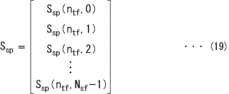
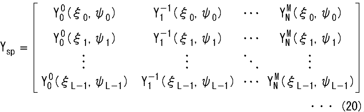
空間周波数合成部42は、このようにして得られた時間周波数スペクトルD(l,ntf)を時間周波数合成部43に供給する。
(時間周波数合成部)
時間周波数合成部43は、次式(21)を計算することで、空間周波数合成部42から供給された時間周波数スペクトルD(l,ntf)に対してIDFT(Inverse Discrete Fourier Transform)(逆離散フーリエ変換)を用いた時間周波数合成を行い、時間信号であるスピーカ駆動信号d(l,nd)を算出する。
時間周波数合成部43は、次式(21)を計算することで、空間周波数合成部42から供給された時間周波数スペクトルD(l,ntf)に対してIDFT(Inverse Discrete Fourier Transform)(逆離散フーリエ変換)を用いた時間周波数合成を行い、時間信号であるスピーカ駆動信号d(l,nd)を算出する。

なお、式(21)において、ndは時間インデックスを示しており、MdtはIDFTのサンプル数を示している。また、式(21)においてjは純虚数を示している。
時間周波数合成部43は、このようにして得られたスピーカ駆動信号d(l,nd)を、スピーカアレイ44を構成する各スピーカユニットに供給し、音声を再生させる。
〈音場再現処理の説明〉
次に、収録音場方向制御器11の動作について説明する。収録音場方向制御器11は、音場の収録と再現が指示されると、音場再現処理を行って収音空間の音場を再生空間で再現する。以下、図7のフローチャートを参照して、収録音場方向制御器11による音場再現処理について説明する。
次に、収録音場方向制御器11の動作について説明する。収録音場方向制御器11は、音場の収録と再現が指示されると、音場再現処理を行って収音空間の音場を再生空間で再現する。以下、図7のフローチャートを参照して、収録音場方向制御器11による音場再現処理について説明する。
ステップS11において、マイクロホンアレイ31は、収音空間においてコンテンツの音声を収音し、その結果得られたマルチチャンネルの収音信号s(i,nt)を時間周波数分析部32に供給する。
ステップS12において、時間周波数分析部32は、マイクロホンアレイ31から供給された収音信号s(i,nt)の時間周波数情報を分析する。
具体的には、時間周波数分析部32は収音信号s(i,nt)を時間周波数変換し、その結果得られた時間周波数スペクトルS(i,ntf)を空間周波数分析部34に供給する。例えば、ステップS12では上述した式(1)の計算が行われる。
ステップS13において、方向補正部33は回転ぶれ補正モードであるか否かを判定する。すなわち、方向補正部33は、外部から補正モード情報を取得し、取得した補正モード情報により示される方向補正モードが回転ぶれ補正モードであるか否かを判定する。
ステップS13において回転ぶれ補正モードであると判定された場合、ステップS14において、方向補正部33は補正角度(α,β)を算出する。
具体的には、方向補正部33は、画像情報およびセンサ情報の少なくとも何れか一方を取得し、取得した情報に基づいてマイクロホンアレイ31の回転角度(θ,φ)を求める。そして、方向補正部33は、得られた回転角度(θ,φ)をそのまま補正角度(α,β)とする。さらに、方向補正部33は、各マイクユニットの角度(θi,φi)からなるマイク配置情報を取得し、取得したマイク配置情報と、求めた補正角度(α,β)とを空間周波数分析部34に供給して、処理はステップS19へと進む。
これに対して、ステップS13において回転ぶれ補正モードでないと判定された場合、ステップS15において、方向補正部33は、補正モード情報により示される方向補正モードがぶれ補正モードであるか否かを判定する。
ステップS15においてぶれ補正モードであると判定された場合、ステップS16において、方向補正部33は画像情報およびセンサ情報の少なくとも何れか一方を取得し、取得した情報に基づいて収録装置21、つまりマイクロホンアレイ31のぶれを検出する。
例えば方向補正部33は、画像情報およびセンサ情報の少なくとも何れか一方に基づいて単位時間当たりの回転角度(θ,φ)を求め、上述した式(3)および式(5)により、仰角および方位角のそれぞれについて、ぶれを検出する。
ステップS17において、方向補正部33は、ステップS16におけるぶれの検出結果に応じて補正角度(α,β)を算出する。
具体的には、方向補正部33は式(3)が満たされて仰角方向のぶれが検出された場合、回転角度(θ,φ)の仰角θをそのまま補正角度(α,β)の仰角の補正角度αとし、仰角方向のぶれが検出されなかった場合、補正角度αを0とする。
また、方向補正部33は式(5)が満たされて方位角方向のぶれが検出された場合、回転角度(θ,φ)の方位角φをそのまま補正角度(α,β)の方位角の補正角度βとし、方位角方向のぶれが検出されなかった場合、補正角度βを0とする。
ステップS18において、方向補正部33は、ぶれの検出結果に応じて基準方向(θref,φref)を更新する。
すなわち、方向補正部33は、仰角方向のぶれが検出された場合、上述した式(4)により仰角θrefを更新し、仰角方向のぶれが検出されなかった場合には、仰角θrefを更新しない。同様に、方向補正部33は、方位角方向のぶれが検出された場合、上述した式(6)により方位角φrefを更新し、方位角方向のぶれが検出されなかった場合には、方位角φrefを更新しない。
このようにして基準方向(θref,φref)が更新されると、方向補正部33はマイク配置情報を取得し、取得したマイク配置情報と、求めた補正角度(α,β)とを空間周波数分析部34に供給して、処理はステップS19へと進む。
また、ステップS15においてぶれ補正モードでないと判定された場合、すなわち補正モード情報により示される方向補正モードが補正無しモードである場合、方向補正部33は、式(7)に示されるように補正角度(α,β)の各角度を0とする。
そして、方向補正部33はマイク配置情報を取得し、取得したマイク配置情報と、補正角度(α,β)とを空間周波数分析部34に供給して、処理はステップS19へと進む。
ステップS14若しくはステップS18の処理が行われたか、またはステップS15においてぶれ補正モードでないと判定された場合、ステップS19において、空間周波数分析部34は、空間周波数変換を行う。
具体的には、空間周波数分析部34は、方向補正部33から供給されたマイク配置情報および補正角度(α,β)と、時間周波数分析部32から供給された時間周波数スペクトルS(i,ntf)とに基づいて、上述した式(11)を計算することで空間周波数変換を行う。
空間周波数分析部34は、空間周波数変換により得られた空間周波数スペクトルSSP(ntf,nsf)を、通信部35に供給する。
ステップS20において、通信部35は、空間周波数分析部34から供給された空間周波数スペクトルSSP(ntf,nsf)を送信する。
ステップS21において、通信部41は、通信部35により送信された空間周波数スペクトルSSP(ntf,nsf)を受信して、空間周波数合成部42に供給する。
ステップS22において、空間周波数合成部42は、通信部41から供給された空間周波数スペクトルSSP(ntf,nsf)と、外部から供給されたスピーカ配置情報とに基づいて、上述した式(17)を計算し、空間周波数逆変換を行う。空間周波数合成部42は、空間周波数逆変換により得られた時間周波数スペクトルD(l,ntf)を時間周波数合成部43に供給する。
ステップS23において、時間周波数合成部43は、上述した式(21)を計算することで、空間周波数合成部42から供給された時間周波数スペクトルD(l,ntf)に対して時間周波数合成を行い、スピーカ駆動信号d(l,nd)を算出する。
時間周波数合成部43は、得られたスピーカ駆動信号d(l,nd)を、スピーカアレイ44を構成する各スピーカユニットに供給する。
ステップS24において、スピーカアレイ44は、時間周波数合成部43から供給されたスピーカ駆動信号d(l,nd)に基づいて音声を再生する。これにより、コンテンツの音声、すなわち収音空間の音場が再現されることになる。
このようにして収音空間の音場が再生空間で再現されると、音場再現処理は終了する。
以上のようにして、収録音場方向制御器11は、方向補正モードに応じて補正角度(α,β)を算出し、空間周波数変換時にその補正角度(α,β)に基づいて補正された各マイクユニットの角度を用いて空間周波数スペクトルSSP(ntf,nsf)を算出する。
このようにすることで、音場の収録時にマイクロホンアレイ31が回転したりぶれたりした場合であっても、必要に応じて収録音場の方向を一定方向に固定することができ、より適切に音場を再現することができる。
〈第2の実施の形態〉
〈収録音場方向制御器の構成例〉
なお、以上においては、空間周波数変換時にマイクユニットの角度を補正することで、収録音場の方向、つまり回転やぶれを補正する例について説明した。しかし、これに限らず、空間周波数逆変換時にスピーカユニットの角度(方向)を補正することにより収録音場の方向を補正してもよい。
〈収録音場方向制御器の構成例〉
なお、以上においては、空間周波数変換時にマイクユニットの角度を補正することで、収録音場の方向、つまり回転やぶれを補正する例について説明した。しかし、これに限らず、空間周波数逆変換時にスピーカユニットの角度(方向)を補正することにより収録音場の方向を補正してもよい。
そのような場合、収録音場方向制御器11は、例えば図8に示すように構成される。なお、図8において図2における場合と対応する部分には同一の符号を付してあり、その説明は適宜省略する。
図8に示す収録音場方向制御器11の構成は、方向補正部33が再生装置22に設けられている点で図2に示した収録音場方向制御器11の構成と異なり、その他の点では図2に示した収録音場方向制御器11と同じ構成となっている。
すなわち、図8に示す収録音場方向制御器11では、収録装置21は、マイクロホンアレイ31、時間周波数分析部32、空間周波数分析部34、および通信部35を有している。また、再生装置22は、通信部41、方向補正部33、空間周波数合成部42、時間周波数合成部43、およびスピーカアレイ44を有している。
この例では、方向補正部33は、図2に示した例と同様に補正モード情報、画像情報、およびセンサ情報を取得して補正角度(α,β)を算出し、得られた補正角度(α,β)を空間周波数合成部42に供給する。
この場合、補正角度(α,β)は、スピーカ配置情報により示される各スピーカユニットの方向を示す角度(ξl,ψl)を補正するための角度となる。
なお、画像情報およびセンサ情報は、収録装置21と再生装置22との間で、通信部35および通信部41により授受されて方向補正部33に供給されるようにしてもよいし、他の方法により方向補正部33により取得されるようにしてもよい。
このように再生装置22側において補正角度(α,β)による角度(方向)の補正が行われる場合、空間周波数分析部34は、外部からマイク配置情報を取得する。そして、空間周波数分析部34は取得したマイク配置情報と、時間周波数分析部32から供給された時間周波数スペクトルS(i,ntf)とに基づいて、上述した式(11)を計算することで空間周波数変換を行う。
但し、この場合、空間周波数分析部34は、マイク配置情報により示されるマイクユニットの角度(θi,φi)から得られる、次式(22)に示す球面調和関数行列Ymicを用いて式(11)の計算を行う。

すなわち、空間周波数分析部34では、マイクユニットの角度(θi,φi)の補正が行われずに空間周波数変換の計算が行われる。
また、空間周波数合成部42では、方向補正部33から供給された補正角度(α,β)に基づいて次式(23)の計算が行われ、スピーカ配置情報により示される各スピーカユニットの方向を示す角度(ξl,ψl)が補正される。

なお、式(23)においてξl’およびψl’は、補正角度(α,β)により角度(ξl,ψl)を補正することで得られた、方向補正後の各スピーカユニットの方向を示す角度である。つまり、仰角ξl’は、補正角度αにより仰角ξlを補正して得られたものであり、方位角ψl’は、補正角度βにより方位角ψlを補正して得られたものである。
このようにして方向補正後のスピーカユニットの角度(ξl’,ψl’)が得られると、空間周波数合成部42はその角度(ξl’,ψl’)から得られる、次式(24)に示す球面調和関数行列YSPを用いて上述した式(17)を計算し、空間周波数逆変換を行う。すなわち、方向補正後のスピーカユニットの角度(ξl’,ψl’)により得られる球面調和関数からなる球面調和関数行列YSPが用いられて、空間周波数逆変換が行われる。

このように空間周波数合成部42では、空間周波数逆変換時に補正角度(α,β)によりスピーカアレイ44の方向を示す角度、より詳細には各スピーカユニットの角度(ξl,ψl)が補正される。
補正角度(α,β)により空間周波数逆変換で用いられる球面調和関数における、スピーカアレイ44の各スピーカユニットの方向を示す角度(ξl,ψl)を補正することで、空間周波数スペクトルSSP(ntf,nsf)が適切に補正される。すなわち、空間周波数逆変換により、適宜、マイクロホンアレイ31の回転やぶれが補正された音場を再現するための時間周波数スペクトルD(l,ntf)を得ることができる。
以上のように図8に示す収録音場方向制御器11では、マイクユニットではなく、スピーカユニットの角度(方向)が補正されて音場が再現される。
〈音場再現処理の説明〉
次に、図9のフローチャートを参照して、図8に示した収録音場方向制御器11により行われる音場再現処理について説明する。
次に、図9のフローチャートを参照して、図8に示した収録音場方向制御器11により行われる音場再現処理について説明する。
なお、ステップS51およびステップS52の処理は、図7のステップS11およびステップS12の処理と同様であるので、その説明は省略する。
ステップS53において、空間周波数分析部34は空間周波数変換を行い、その結果得られた空間周波数スペクトルSSP(ntf,nsf)を通信部35に供給する。
具体的には、空間周波数分析部34はマイク配置情報を取得し、そのマイク配置情報から得られる式(22)に示した球面調和関数行列Ymicと、時間周波数分析部32から供給された時間周波数スペクトルS(i,ntf)とに基づいて、式(11)を計算することで空間周波数変換を行う。
空間周波数変換により空間周波数スペクトルSSP(ntf,nsf)が得られると、その後、ステップS54およびステップS55の処理が行われて、空間周波数スペクトルSSP(ntf,nsf)が空間周波数合成部42に供給される。なお、これらのステップS54およびステップS55の処理は図7のステップS20およびステップS21の処理と同様であるので、その説明は省略する。
また、ステップS55の処理が行われると、その後、ステップS56乃至ステップS61の処理が行われて、スピーカアレイ44の各スピーカユニットの角度(ξl,ψl)を補正するための補正角度(α,β)が算出される。なお、これらのステップS56乃至ステップS61の処理は、図7のステップS13乃至ステップS18の処理と同様であるので、その説明は省略する。
ステップS56乃至ステップS61の処理が行われて補正角度(α,β)が得られると、方向補正部33は、得られた補正角度(α,β)を空間周波数合成部42に供給し、その後、処理はステップS62に進む。
ステップS62において、空間周波数合成部42は、スピーカ配置情報を取得し、取得したスピーカ配置情報、方向補正部33から供給された補正角度(α,β)、および通信部41から供給された空間周波数スペクトルSSP(ntf,nsf)に基づいて空間周波数逆変換を行う。
具体的には空間周波数合成部42は、スピーカ配置情報と補正角度(α,β)に基づいて式(23)を計算し、式(24)に示した球面調和関数行列YSPを得る。さらに、空間周波数合成部42は、得られた球面調和関数行列YSPと、空間周波数スペクトルSSP(ntf,nsf)とに基づいて式(17)を計算し、時間周波数スペクトルD(l,ntf)を算出する。
空間周波数合成部42は、空間周波数逆変換により得られた時間周波数スペクトルD(l,ntf)を時間周波数合成部43に供給する。
すると、その後、ステップS63およびステップS64の処理が行われて音場再現処理は終了するが、これらの処理は図7のステップS23およびステップS24の処理と同様であるので、その説明は省略する。
以上のようにして、収録音場方向制御器11は、方向補正モードに応じて補正角度(α,β)を算出し、空間周波数逆変換時にその補正角度(α,β)に基づいて補正された各スピーカユニットの角度を用いて時間周波数スペクトルD(l,ntf)を算出する。
このようにすることで、音場の収録時にマイクロホンアレイ31が回転したりぶれたりした場合であっても、必要に応じて収録音場の方向を一定方向に固定することができ、より適切に音場を再現することができる。
なお、以上においては、マイクロホンアレイ31として、環状マイクロホンアレイや球状マイクロホンアレイを例として説明したが、マイクロホンアレイ31として直線マイクロホンアレイを用いるようにしてもよい。そのような場合においても以上において説明した処理と同様の処理により音場を再現することが可能である。
また、スピーカアレイ44も環状スピーカアレイや球状スピーカアレイに限らず、直線スピーカアレイなど、どのようなものであってもよい。
ところで、上述した一連の処理は、ハードウェアにより実行することもできるし、ソフトウェアにより実行することもできる。一連の処理をソフトウェアにより実行する場合には、そのソフトウェアを構成するプログラムが、コンピュータにインストールされる。ここで、コンピュータには、専用のハードウェアに組み込まれているコンピュータや、各種のプログラムをインストールすることで、各種の機能を実行することが可能な、例えば汎用のコンピュータなどが含まれる。
図10は、上述した一連の処理をプログラムにより実行するコンピュータのハードウェアの構成例を示すブロック図である。
コンピュータにおいて、CPU(Central Processing Unit)501,ROM(Read Only Memory)502,RAM(Random Access Memory)503は、バス504により相互に接続されている。
バス504には、さらに、入出力インターフェース505が接続されている。入出力インターフェース505には、入力部506、出力部507、記録部508、通信部509、及びドライブ510が接続されている。
入力部506は、キーボード、マウス、マイクロホン、撮像素子などよりなる。出力部507は、ディスプレイ、スピーカなどよりなる。記録部508は、ハードディスクや不揮発性のメモリなどよりなる。通信部509は、ネットワークインターフェースなどよりなる。ドライブ510は、磁気ディスク、光ディスク、光磁気ディスク、又は半導体メモリなどのリムーバブルメディア511を駆動する。
以上のように構成されるコンピュータでは、CPU501が、例えば、記録部508に記録されているプログラムを、入出力インターフェース505及びバス504を介して、RAM503にロードして実行することにより、上述した一連の処理が行われる。
コンピュータ(CPU501)が実行するプログラムは、例えば、パッケージメディア等としてのリムーバブルメディア511に記録して提供することができる。また、プログラムは、ローカルエリアネットワーク、インターネット、デジタル衛星放送といった、有線または無線の伝送媒体を介して提供することができる。
コンピュータでは、プログラムは、リムーバブルメディア511をドライブ510に装着することにより、入出力インターフェース505を介して、記録部508にインストールすることができる。また、プログラムは、有線または無線の伝送媒体を介して、通信部509で受信し、記録部508にインストールすることができる。その他、プログラムは、ROM502や記録部508に、あらかじめインストールしておくことができる。
なお、コンピュータが実行するプログラムは、本明細書で説明する順序に沿って時系列に処理が行われるプログラムであっても良いし、並列に、あるいは呼び出しが行われたとき等の必要なタイミングで処理が行われるプログラムであっても良い。
また、本技術の実施の形態は、上述した実施の形態に限定されるものではなく、本技術の要旨を逸脱しない範囲において種々の変更が可能である。
例えば、本技術は、1つの機能をネットワークを介して複数の装置で分担、共同して処理するクラウドコンピューティングの構成をとることができる。
また、上述のフローチャートで説明した各ステップは、1つの装置で実行する他、複数の装置で分担して実行することができる。
さらに、1つのステップに複数の処理が含まれる場合には、その1つのステップに含まれる複数の処理は、1つの装置で実行する他、複数の装置で分担して実行することができる。
また、本明細書中に記載された効果はあくまで例示であって限定されるものではなく、他の効果があってもよい。
さらに、本技術は、以下の構成とすることも可能である。
(1)
マイクロホンアレイにより収音して得られた収音信号を、前記マイクロホンアレイの方向を示す方向情報に基づいて補正する補正部を備える
音声処理装置。
(2)
前記方向情報は、所定の基準方向からの前記マイクロホンアレイの方向の角度を示す情報である
(1)に記載の音声処理装置。
(3)
前記補正部は、前記方向情報に基づいて、前記収音信号から得られた空間周波数スペクトルを補正する
(1)または(2)に記載の音声処理装置。
(4)
前記補正部は、前記収音信号から得られた時間周波数スペクトルに対する空間周波数変換時に前記補正を行う
(3)に記載の音声処理装置。
(5)
前記補正部は、前記空間周波数変換に用いる球面調和関数における前記マイクロホンアレイの方向を示す角度を前記方向情報に基づいて補正する
(4)に記載の音声処理装置。
(6)
前記補正部は、前記収音信号から得られた空間周波数スペクトルに対する空間周波数逆変換時に前記補正を行う
(3)に記載の音声処理装置。
(7)
前記補正部は、前記空間周波数逆変換に用いる球面調和関数における、前記収音信号に基づく音声を再生するスピーカアレイの方向を示す角度を前記方向情報に基づいて補正する
(6)に記載の音声処理装置。
(8)
前記補正部は、前記マイクロホンアレイの単位時間当たりの変位、角速度、または加速度に応じて前記収音信号を補正する
(1)乃至(7)の何れか一項に記載の音声処理装置。
(9)
前記マイクロホンアレイは、環状マイクロホンアレイまたは球状マイクロホンアレイである
(1)乃至(8)の何れか一項に記載の音声処理装置。
(10)
マイクロホンアレイにより収音して得られた収音信号を、前記マイクロホンアレイの方向を示す方向情報に基づいて補正する
ステップを含む音声処理方法。
(11)
マイクロホンアレイにより収音して得られた収音信号を、前記マイクロホンアレイの方向を示す方向情報に基づいて補正する
ステップを含む処理をコンピュータに実行させるプログラム。
マイクロホンアレイにより収音して得られた収音信号を、前記マイクロホンアレイの方向を示す方向情報に基づいて補正する補正部を備える
音声処理装置。
(2)
前記方向情報は、所定の基準方向からの前記マイクロホンアレイの方向の角度を示す情報である
(1)に記載の音声処理装置。
(3)
前記補正部は、前記方向情報に基づいて、前記収音信号から得られた空間周波数スペクトルを補正する
(1)または(2)に記載の音声処理装置。
(4)
前記補正部は、前記収音信号から得られた時間周波数スペクトルに対する空間周波数変換時に前記補正を行う
(3)に記載の音声処理装置。
(5)
前記補正部は、前記空間周波数変換に用いる球面調和関数における前記マイクロホンアレイの方向を示す角度を前記方向情報に基づいて補正する
(4)に記載の音声処理装置。
(6)
前記補正部は、前記収音信号から得られた空間周波数スペクトルに対する空間周波数逆変換時に前記補正を行う
(3)に記載の音声処理装置。
(7)
前記補正部は、前記空間周波数逆変換に用いる球面調和関数における、前記収音信号に基づく音声を再生するスピーカアレイの方向を示す角度を前記方向情報に基づいて補正する
(6)に記載の音声処理装置。
(8)
前記補正部は、前記マイクロホンアレイの単位時間当たりの変位、角速度、または加速度に応じて前記収音信号を補正する
(1)乃至(7)の何れか一項に記載の音声処理装置。
(9)
前記マイクロホンアレイは、環状マイクロホンアレイまたは球状マイクロホンアレイである
(1)乃至(8)の何れか一項に記載の音声処理装置。
(10)
マイクロホンアレイにより収音して得られた収音信号を、前記マイクロホンアレイの方向を示す方向情報に基づいて補正する
ステップを含む音声処理方法。
(11)
マイクロホンアレイにより収音して得られた収音信号を、前記マイクロホンアレイの方向を示す方向情報に基づいて補正する
ステップを含む処理をコンピュータに実行させるプログラム。
11 収録音場方向制御器, 21 収録装置, 22 再生装置, 31 マイクロホンアレイ, 32 時間周波数分析部, 33 方向補正部, 34 空間周波数分析部, 42 空間周波数合成部, 43 時間周波数合成部, 44 スピーカアレイ
Claims (11)
- マイクロホンアレイにより収音して得られた収音信号を、前記マイクロホンアレイの方向を示す方向情報に基づいて補正する補正部を備える
音声処理装置。 - 前記方向情報は、所定の基準方向からの前記マイクロホンアレイの方向の角度を示す情報である
請求項1に記載の音声処理装置。 - 前記補正部は、前記方向情報に基づいて、前記収音信号から得られた空間周波数スペクトルを補正する
請求項1に記載の音声処理装置。 - 前記補正部は、前記収音信号から得られた時間周波数スペクトルに対する空間周波数変換時に前記補正を行う
請求項3に記載の音声処理装置。 - 前記補正部は、前記空間周波数変換に用いる球面調和関数における前記マイクロホンアレイの方向を示す角度を前記方向情報に基づいて補正する
請求項4に記載の音声処理装置。 - 前記補正部は、前記収音信号から得られた空間周波数スペクトルに対する空間周波数逆変換時に前記補正を行う
請求項3に記載の音声処理装置。 - 前記補正部は、前記空間周波数逆変換に用いる球面調和関数における、前記収音信号に基づく音声を再生するスピーカアレイの方向を示す角度を前記方向情報に基づいて補正する
請求項6に記載の音声処理装置。 - 前記補正部は、前記マイクロホンアレイの単位時間当たりの変位、角速度、または加速度に応じて前記収音信号を補正する
請求項1に記載の音声処理装置。 - 前記マイクロホンアレイは、環状マイクロホンアレイまたは球状マイクロホンアレイである
請求項1に記載の音声処理装置。 - マイクロホンアレイにより収音して得られた収音信号を、前記マイクロホンアレイの方向を示す方向情報に基づいて補正する
ステップを含む音声処理方法。 - マイクロホンアレイにより収音して得られた収音信号を、前記マイクロホンアレイの方向を示す方向情報に基づいて補正する
ステップを含む処理をコンピュータに実行させるプログラム。
Priority Applications (3)
| Application Number | Priority Date | Filing Date | Title |
|---|---|---|---|
| EP16841575.0A EP3346728A4 (en) | 2015-09-03 | 2016-08-23 | SOUND PROCESSING DEVICE, METHOD AND PROGRAM |
| US15/754,795 US10674255B2 (en) | 2015-09-03 | 2016-08-23 | Sound processing device, method and program |
| US16/863,689 US11265647B2 (en) | 2015-09-03 | 2020-04-30 | Sound processing device, method and program |
Applications Claiming Priority (2)
| Application Number | Priority Date | Filing Date | Title |
|---|---|---|---|
| JP2015174151 | 2015-09-03 | ||
| JP2015-174151 | 2015-09-03 |
Related Child Applications (2)
| Application Number | Title | Priority Date | Filing Date |
|---|---|---|---|
| US15/754,795 A-371-Of-International US10674255B2 (en) | 2015-09-03 | 2016-08-23 | Sound processing device, method and program |
| US16/863,689 Continuation US11265647B2 (en) | 2015-09-03 | 2020-04-30 | Sound processing device, method and program |
Publications (1)
| Publication Number | Publication Date |
|---|---|
| WO2017038543A1 true WO2017038543A1 (ja) | 2017-03-09 |
Family
ID=58187342
Family Applications (1)
| Application Number | Title | Priority Date | Filing Date |
|---|---|---|---|
| PCT/JP2016/074453 Ceased WO2017038543A1 (ja) | 2015-09-03 | 2016-08-23 | 音声処理装置および方法、並びにプログラム |
Country Status (3)
| Country | Link |
|---|---|
| US (2) | US10674255B2 (ja) |
| EP (1) | EP3346728A4 (ja) |
| WO (1) | WO2017038543A1 (ja) |
Cited By (1)
| Publication number | Priority date | Publication date | Assignee | Title |
|---|---|---|---|---|
| JP2023027280A (ja) * | 2017-03-14 | 2023-03-01 | 株式会社リコー | 音響装置、撮像装置、音響システム、方法およびプログラム |
Families Citing this family (4)
| Publication number | Priority date | Publication date | Assignee | Title |
|---|---|---|---|---|
| JP6485711B2 (ja) | 2014-04-16 | 2019-03-20 | ソニー株式会社 | 音場再現装置および方法、並びにプログラム |
| US10674255B2 (en) | 2015-09-03 | 2020-06-02 | Sony Corporation | Sound processing device, method and program |
| WO2017098949A1 (ja) | 2015-12-10 | 2017-06-15 | ソニー株式会社 | 音声処理装置および方法、並びにプログラム |
| US11031028B2 (en) | 2016-09-01 | 2021-06-08 | Sony Corporation | Information processing apparatus, information processing method, and recording medium |
Citations (4)
| Publication number | Priority date | Publication date | Assignee | Title |
|---|---|---|---|---|
| JPH05284591A (ja) * | 1992-04-03 | 1993-10-29 | Matsushita Electric Ind Co Ltd | 超指向性マイクロホン |
| JP2005333211A (ja) * | 2004-05-18 | 2005-12-02 | Sony Corp | 音響収録方法、音響収録再生方法、音響収録装置および音響再生装置 |
| JP2013520858A (ja) * | 2010-02-23 | 2013-06-06 | コーニンクレッカ フィリップス エレクトロニクス エヌ ヴィ | 音源位置決め |
| JP2015027046A (ja) * | 2013-07-29 | 2015-02-05 | 日本電信電話株式会社 | 音場収音再生装置、方法及びプログラム |
Family Cites Families (26)
| Publication number | Priority date | Publication date | Assignee | Title |
|---|---|---|---|---|
| NL8800745A (nl) | 1988-03-24 | 1989-10-16 | Augustinus Johannes Berkhout | Werkwijze en inrichting voor het creeren van een variabele akoestiek in een ruimte. |
| JPH04132468A (ja) * | 1990-09-25 | 1992-05-06 | Sony Corp | ビデオカメラ |
| JP3929863B2 (ja) * | 2002-09-20 | 2007-06-13 | 株式会社国際電気通信基礎技術研究所 | マイクロホンアレーにおけるマイクロホン受信信号の補正方法および補正装置 |
| US8689793B2 (en) * | 2006-01-23 | 2014-04-08 | Bob Kring | Method and apparatus for restraining a patient's leg during leg surgical and interventional procedures |
| WO2007091849A1 (en) | 2006-02-07 | 2007-08-16 | Lg Electronics Inc. | Apparatus and method for encoding/decoding signal |
| JP5315865B2 (ja) | 2008-09-02 | 2013-10-16 | ヤマハ株式会社 | 音場伝送システムおよび音場伝送方法 |
| JP2010193323A (ja) | 2009-02-19 | 2010-09-02 | Casio Hitachi Mobile Communications Co Ltd | 録音装置、再生装置、録音方法、再生方法、及びコンピュータプログラム |
| US9036843B2 (en) | 2010-02-05 | 2015-05-19 | 2236008 Ontario, Inc. | Enhanced spatialization system |
| US20130332156A1 (en) * | 2012-06-11 | 2013-12-12 | Apple Inc. | Sensor Fusion to Improve Speech/Audio Processing in a Mobile Device |
| WO2013186593A1 (en) * | 2012-06-14 | 2013-12-19 | Nokia Corporation | Audio capture apparatus |
| JP5983313B2 (ja) | 2012-10-30 | 2016-08-31 | 富士通株式会社 | 情報処理装置、音像定位強調方法、及び音像定位強調プログラム |
| JP2014215461A (ja) | 2013-04-25 | 2014-11-17 | ソニー株式会社 | 音声処理装置および方法、並びにプログラム |
| US10582330B2 (en) | 2013-05-16 | 2020-03-03 | Koninklijke Philips N.V. | Audio processing apparatus and method therefor |
| DE102013218176A1 (de) | 2013-09-11 | 2015-03-12 | Fraunhofer-Gesellschaft zur Förderung der angewandten Forschung e.V. | Vorrichtung und verfahren zur dekorrelation von lautsprechersignalen |
| JP2015095802A (ja) | 2013-11-13 | 2015-05-18 | ソニー株式会社 | 表示制御装置、表示制御方法、およびプログラム |
| JP6458738B2 (ja) | 2013-11-19 | 2019-01-30 | ソニー株式会社 | 音場再現装置および方法、並びにプログラム |
| EP2884489B1 (en) | 2013-12-16 | 2020-02-05 | Harman Becker Automotive Systems GmbH | Sound system including an engine sound synthesizer |
| JP6253671B2 (ja) | 2013-12-26 | 2017-12-27 | 株式会社東芝 | 電子機器、制御方法およびプログラム |
| BR112016015971B1 (pt) | 2014-01-16 | 2022-11-16 | Sony Corporation | Dispositivo e método de processamento de áudio, e, mídia de armazenamento legível por computador |
| JP6485711B2 (ja) | 2014-04-16 | 2019-03-20 | ソニー株式会社 | 音場再現装置および方法、並びにプログラム |
| US10602266B2 (en) | 2014-10-10 | 2020-03-24 | Sony Corporation | Audio processing apparatus and method, and program |
| US9508335B2 (en) | 2014-12-05 | 2016-11-29 | Stages Pcs, Llc | Active noise control and customized audio system |
| WO2016167138A1 (ja) | 2015-04-13 | 2016-10-20 | ソニー株式会社 | 信号処理装置および方法、並びにプログラム |
| US10674255B2 (en) | 2015-09-03 | 2020-06-02 | Sony Corporation | Sound processing device, method and program |
| WO2017098949A1 (ja) | 2015-12-10 | 2017-06-15 | ソニー株式会社 | 音声処理装置および方法、並びにプログラム |
| US11031028B2 (en) | 2016-09-01 | 2021-06-08 | Sony Corporation | Information processing apparatus, information processing method, and recording medium |
-
2016
- 2016-08-23 US US15/754,795 patent/US10674255B2/en active Active
- 2016-08-23 WO PCT/JP2016/074453 patent/WO2017038543A1/ja not_active Ceased
- 2016-08-23 EP EP16841575.0A patent/EP3346728A4/en not_active Withdrawn
-
2020
- 2020-04-30 US US16/863,689 patent/US11265647B2/en active Active
Patent Citations (4)
| Publication number | Priority date | Publication date | Assignee | Title |
|---|---|---|---|---|
| JPH05284591A (ja) * | 1992-04-03 | 1993-10-29 | Matsushita Electric Ind Co Ltd | 超指向性マイクロホン |
| JP2005333211A (ja) * | 2004-05-18 | 2005-12-02 | Sony Corp | 音響収録方法、音響収録再生方法、音響収録装置および音響再生装置 |
| JP2013520858A (ja) * | 2010-02-23 | 2013-06-06 | コーニンクレッカ フィリップス エレクトロニクス エヌ ヴィ | 音源位置決め |
| JP2015027046A (ja) * | 2013-07-29 | 2015-02-05 | 日本電信電話株式会社 | 音場収音再生装置、方法及びプログラム |
Non-Patent Citations (2)
| Title |
|---|
| AKIO ANDO: "Butsuri Onkyo Model ni Motozuku Onkyo System no Kenkyu Doko", NHK SCIENCE AND TECHNICAL RESEARCH LABORATORIES R&D REPORT, NO. 126 , NHK SCIENCE AND TECHNICAL RESEARCH LABORATORIES, March 2011 (2011-03-01), pages 19 - 22, XP009510250, Retrieved from the Internet <URL:https://www.nhk.or.jp/strl/publica/rd/rd126/PDF/P14-25.PDF> [retrieved on 20161107] * |
| See also references of EP3346728A4 * |
Cited By (2)
| Publication number | Priority date | Publication date | Assignee | Title |
|---|---|---|---|---|
| JP2023027280A (ja) * | 2017-03-14 | 2023-03-01 | 株式会社リコー | 音響装置、撮像装置、音響システム、方法およびプログラム |
| JP7533563B2 (ja) | 2017-03-14 | 2024-08-14 | 株式会社リコー | 音響装置、撮像装置、音響システム、方法およびプログラム |
Also Published As
| Publication number | Publication date |
|---|---|
| EP3346728A1 (en) | 2018-07-11 |
| EP3346728A4 (en) | 2019-04-24 |
| US20180249244A1 (en) | 2018-08-30 |
| US11265647B2 (en) | 2022-03-01 |
| US20200260179A1 (en) | 2020-08-13 |
| US10674255B2 (en) | 2020-06-02 |
Similar Documents
| Publication | Publication Date | Title |
|---|---|---|
| JP6841229B2 (ja) | 音声処理装置および方法、並びにプログラム | |
| US11265647B2 (en) | Sound processing device, method and program | |
| US10448192B2 (en) | Apparatus and method of audio stabilizing | |
| EP3484184A1 (en) | Acoustic field formation device, method, and program | |
| US10582329B2 (en) | Audio processing device and method | |
| CN108346432B (zh) | 虚拟现实vr音频的处理方法及相应设备 | |
| JPWO2018008396A1 (ja) | 音場形成装置および方法、並びにプログラム | |
| US10595148B2 (en) | Sound processing apparatus and method, and program | |
| CN113767432A (zh) | 音频处理方法、音频处理装置、电子设备 | |
| US12108242B2 (en) | Signal processing device and signal processing method | |
| WO2021212287A1 (zh) | 音频信号处理方法、音频处理装置及录音设备 | |
| WO2020031594A1 (ja) | 音源分離システム、音源位置推定システム、音源分離方法および音源分離プログラム | |
| US10764684B1 (en) | Binaural audio using an arbitrarily shaped microphone array | |
| WO2018211984A1 (ja) | スピーカアレイ、および信号処理装置 | |
| CN120581021B (zh) | 音频变焦方法、电子设备、存储介质及计算机程序产品 | |
| US20250380104A1 (en) | Information processing apparatus, information processing method, and non-transitory computer-readable storage medium | |
| CN111145793B (zh) | 音频处理方法和装置 | |
| JP7260821B2 (ja) | 信号処理装置、信号処理方法および信号処理プログラム | |
| WO2024008313A1 (en) | Head-related transfer function calculation | |
| JP2017204869A (ja) | 再生処理装置、撮像装置および再生処理プログラム | |
| WO2018066376A1 (ja) | 信号処理装置および方法、並びにプログラム | |
| JP6167483B2 (ja) | 再生処理装置、撮像装置および再生処理プログラム | |
| CN121171244A (zh) | 风噪抑制方法、装置、设备及存储介质 | |
| CN121367873A (zh) | 用于确定预定空间中的扬声器布置的方法、装置和电子设备 | |
| AU2021357463A1 (en) | Information processing device, method, and program |
Legal Events
| Date | Code | Title | Description |
|---|---|---|---|
| 121 | Ep: the epo has been informed by wipo that ep was designated in this application |
Ref document number: 16841575 Country of ref document: EP Kind code of ref document: A1 |
|
| WWE | Wipo information: entry into national phase |
Ref document number: 15754795 Country of ref document: US |
|
| NENP | Non-entry into the national phase |
Ref country code: DE |
|
| NENP | Non-entry into the national phase |
Ref country code: JP |