WO2017038746A1 - 水洗式便器 - Google Patents
水洗式便器 Download PDFInfo
- Publication number
- WO2017038746A1 WO2017038746A1 PCT/JP2016/075156 JP2016075156W WO2017038746A1 WO 2017038746 A1 WO2017038746 A1 WO 2017038746A1 JP 2016075156 W JP2016075156 W JP 2016075156W WO 2017038746 A1 WO2017038746 A1 WO 2017038746A1
- Authority
- WO
- WIPO (PCT)
- Prior art keywords
- toilet
- flapper
- valve
- toilet bowl
- drainage path
- Prior art date
- Legal status (The legal status is an assumption and is not a legal conclusion. Google has not performed a legal analysis and makes no representation as to the accuracy of the status listed.)
- Ceased
Links
Images










Classifications
-
- E—FIXED CONSTRUCTIONS
- E03—WATER SUPPLY; SEWERAGE
- E03D—WATER-CLOSETS OR URINALS WITH FLUSHING DEVICES; FLUSHING VALVES THEREFOR
- E03D9/00—Sanitary or other accessories for lavatories ; Devices for cleaning or disinfecting the toilet room or the toilet bowl; Devices for eliminating smells
- E03D9/005—Devices adding disinfecting or deodorising agents to the bowl
-
- E—FIXED CONSTRUCTIONS
- E03—WATER SUPPLY; SEWERAGE
- E03D—WATER-CLOSETS OR URINALS WITH FLUSHING DEVICES; FLUSHING VALVES THEREFOR
- E03D11/00—Other component parts of water-closets, e.g. noise-reducing means in the flushing system, flushing pipes mounted in the bowl, seals for the bowl outlet, devices preventing overflow of the bowl contents; devices forming a water seal in the bowl after flushing, devices eliminating obstructions in the bowl outlet or preventing backflow of water and excrements from the waterpipe
- E03D11/02—Water-closet bowls ; Bowls with a double odour seal optionally with provisions for a good siphonic action; siphons as part of the bowl
- E03D11/10—Bowls with closure elements provided between bottom or outlet and the outlet pipe; Bowls with pivotally supported inserts
-
- E—FIXED CONSTRUCTIONS
- E03—WATER SUPPLY; SEWERAGE
- E03D—WATER-CLOSETS OR URINALS WITH FLUSHING DEVICES; FLUSHING VALVES THEREFOR
- E03D11/00—Other component parts of water-closets, e.g. noise-reducing means in the flushing system, flushing pipes mounted in the bowl, seals for the bowl outlet, devices preventing overflow of the bowl contents; devices forming a water seal in the bowl after flushing, devices eliminating obstructions in the bowl outlet or preventing backflow of water and excrements from the waterpipe
- E03D11/13—Parts or details of bowls; Special adaptations of pipe joints or couplings for use with bowls, e.g. provisions in bowl construction preventing backflow of waste-water from the bowl in the flushing pipe or cistern, provisions for a secondary flushing, for noise-reducing
-
- F—MECHANICAL ENGINEERING; LIGHTING; HEATING; WEAPONS; BLASTING
- F16—ENGINEERING ELEMENTS AND UNITS; GENERAL MEASURES FOR PRODUCING AND MAINTAINING EFFECTIVE FUNCTIONING OF MACHINES OR INSTALLATIONS; THERMAL INSULATION IN GENERAL
- F16K—VALVES; TAPS; COCKS; ACTUATING-FLOATS; DEVICES FOR VENTING OR AERATING
- F16K1/00—Lift valves or globe valves, i.e. cut-off apparatus with closure members having at least a component of their opening and closing motion perpendicular to the closing faces
- F16K1/16—Lift valves or globe valves, i.e. cut-off apparatus with closure members having at least a component of their opening and closing motion perpendicular to the closing faces with pivoted closure-members
-
- F—MECHANICAL ENGINEERING; LIGHTING; HEATING; WEAPONS; BLASTING
- F16—ENGINEERING ELEMENTS AND UNITS; GENERAL MEASURES FOR PRODUCING AND MAINTAINING EFFECTIVE FUNCTIONING OF MACHINES OR INSTALLATIONS; THERMAL INSULATION IN GENERAL
- F16K—VALVES; TAPS; COCKS; ACTUATING-FLOATS; DEVICES FOR VENTING OR AERATING
- F16K31/00—Actuating devices; Operating means; Releasing devices
- F16K31/02—Actuating devices; Operating means; Releasing devices electric; magnetic
- F16K31/06—Actuating devices; Operating means; Releasing devices electric; magnetic using a magnet, e.g. diaphragm valves, cutting off by means of a liquid
- F16K31/0675—Electromagnet aspects, e.g. electric supply therefor
-
- F—MECHANICAL ENGINEERING; LIGHTING; HEATING; WEAPONS; BLASTING
- F16—ENGINEERING ELEMENTS AND UNITS; GENERAL MEASURES FOR PRODUCING AND MAINTAINING EFFECTIVE FUNCTIONING OF MACHINES OR INSTALLATIONS; THERMAL INSULATION IN GENERAL
- F16K—VALVES; TAPS; COCKS; ACTUATING-FLOATS; DEVICES FOR VENTING OR AERATING
- F16K31/00—Actuating devices; Operating means; Releasing devices
- F16K31/44—Mechanical actuating means
Definitions
- the present invention relates to a flush toilet.
- This application claims priority based on Japanese Patent Application No. 2015-171217 filed in Japan on August 31, 2015, the contents of which are incorporated herein by reference.
- a flush toilet that drives the washing water supply means with electric power
- the washing water supply means may not operate and the toilet bowl may not be washed.
- cleaning water is supplied by electrical drive at the time of a power failure, and a valve in the drain socket is opened and closed by any one of manual operation, emergency power supply, and mechanical elements.
- a flush toilet is disclosed in which water is stored in a section for washing.
- an object of the present invention is to provide a flush toilet bowl having many parts that can be shared by the floor drainage toilet and the floor drainage toilet and having improved versatility.
- a flush toilet according to the first aspect of the present invention is provided in the toilet bowl, the toilet bowl and the drain socket, the toilet drain path through which flush water flows from the toilet bowl, and the toilet drain path.
- a rotation shaft and a flapper connected to the rotation shaft and rotatably provided around the rotation shaft; and a valve portion that opens and closes the toilet drainage path.
- valve part is provided in the toilet drainage path, even when the position of the drain pipe provided in the installation location of the flush toilet is provided on the floor (floor drainage toilet), it is provided on the wall. Even if it is used (floor drainage toilet), it is not necessary to change the configuration of the valve. Therefore, there are many parts that can be shared by the floor drainage toilet and the floor drainage toilet, and a flush toilet that can improve versatility can be provided.
- the valve portion includes a valve portion main body that constitutes a part of the toilet drainage path, and the rotating shaft and the flapper include the valve
- the valve body and the flapper may be made of resin.
- a resin valve body and a flapper can be provided in a part of the toilet drainage path. Therefore, a valve part can be provided in the toilet drainage path which was difficult to provide in the conventional flush toilet.
- valve body in the flush toilet bowl according to the second aspect, may be an integrally formed member.
- valve body is an integrally formed member, there is no seam or the like of the member in the drain pipe. Therefore, it is possible to prevent sewage and filth from adhering to the drain pipe.
- the connecting portion between the rotating shaft and the flapper and the rotating shaft are located at the top of the toilet drainage path. It may be provided.
- the rotating shaft and the connecting portion between the rotating shaft and the flapper are provided at the top of the toilet drainage path where sewage and dirt are difficult to reach during drainage. For this reason, it is possible to prevent sewage and filth from adhering between the rotating shaft and the connecting portion of the flapper.
- an upper portion is at least in a height direction from the upstream side in the conduit through which the flush water of the valve body flows.
- An enlarged portion that expands may be provided, and the enlarged portion may be provided with a connecting portion between the pivot shaft and the flapper and the pivot shaft.
- the enlarged portion is formed so that the upper part of the pipeline is larger on the downstream side than on the upstream side, so that it is difficult for sewage and filth to reach the enlarged portion during drainage. Since the connecting portion between the rotating shaft and the flapper is provided in such an enlarged portion, it is possible to prevent sewage and dirt from adhering between the connecting portions between the rotating shaft and the flapper.
- a sixth aspect of the present invention is the flush toilet according to any one of the first to fifth aspects, wherein the valve portion is in a state where the flapper is opened, and the inner wall of the toilet drainage path and the flapper You may be comprised so that a clearance gap may be formed between peripheral parts.
- the gap is formed between the inner wall of the toilet drainage path and the peripheral edge of the flapper with the flapper opened, so that the siphon effect can be enhanced when the cleaning water is drained. It is easy to control the flow of drainage.
- the valve portion faces the inner wall of the toilet drainage path with the flapper opened. You may be comprised so that between the peripheral parts of a flapper may be kept watertight.
- the gap between the peripheral edge of the flapper and the inner wall of the toilet drainage path is kept watertight, and the drainage is prevented from flowing between the flapper and the inner wall of the toilet drainage path. It is possible to prevent sewage and filth from adhering to the flapper.
- the flush toilet of the present invention it is possible to wash the toilet bowl without using electric power at the time of a power outage, and there are many parts that can be shared with the floor drainage toilet and the floor drainage toilet, thereby enhancing versatility.
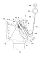
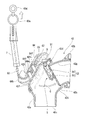
- FIG. 1 and 2 are cross-sectional views of a flush toilet 1 according to the present embodiment.
- FIG. 1 shows the opened state of the valve portion
- FIG. 2 shows the closed state of the valve portion.
- the flush toilet 1 is a so-called siphon wash-out type Western-style toilet, and includes a toilet body 2, a toilet bowl 3, a toilet drainage path 4, and a valve portion 5.
- the toilet body 2, the toilet bowl 3, and a part of the toilet drainage path 4 are integrally formed of ceramic.
- the toilet drainage path 4 and the drainage socket 10 constitute a drainage pipe.
- the direction in which the face of the user seated on the toilet seat 11 faces is defined as the front, and the direction in which the user seated on the toilet seat 11 faces is defined as the back.
- the toilet drainage path 4 communicates with an opening at the bottom of the toilet bowl 3 and communicates with a drain socket 10 on the downstream side.
- the toilet drainage path 4 has a water storage part 4a, an ascending part 4b, a top part 4c, and a descending part 4d in order from the upstream of the flow path of the washing water.
- valve unit 5 In the toilet drainage path 4, a valve portion 5 is provided. Specifically, the valve unit 5 is located between the water reservoir 4a and the drain socket 10 and is located at the top 4c.
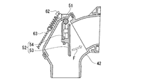
- FIG. 3 shows a side view of the valve unit 5.
- FIG. 4 shows a cross-sectional view of the valve portion 5 in the valve open state.
- FIG. 5 shows a cross-sectional view of the valve portion 5 in a closed state.
- the valve unit 5 includes a valve unit main body 42, a rotating shaft 51, and a flapper 52.
- the valve body 42 is an integrally molded member made of resin. As shown in FIG. 2, the valve body 42 is joined in a watertight manner with the downstream end of the ceramic ascending portion 4 b and the sealing material 44 interposed therebetween. As shown in FIG. 3, the valve part main body 42 is provided with the flowing water pipe part 42a.
- the flowing water pipe part 42 a forms a pipe line that curves downward between the joint part 42 b with the rising part 4 b and the lower end opening part 42 c connected to the drain socket 10.
- the flowing water pipe part 42 a constitutes a part of the toilet drainage path 4.
- the upper part of the curved part of the flowing water pipe part 42a (the top part 4c of the toilet drainage path 4) has an enlarged part 42d where the pipe line is wider than the joint part 42b side (upstream side).
- the enlarged portion 42d serves as an air reservoir where air remains even during running water.
- the enlarged portion 42d is formed with such a dimension that a rotation shaft and a flapper described later can be arranged.
- a stepped portion 42e is provided at a lower portion of the curved portion of the flowing water pipe portion 42a so that the pipe line is wider than the joint portion 42b side (upstream side).
- Rotating shaft 51 is provided at the top 4c of the toilet drainage path 4. Specifically, the rotation shaft 51 is provided at the upper part of the curved portion of the flowing water pipe portion 42a. The rotation shaft 51 extends in a direction perpendicular to the flow path, and is attached so that both end portions penetrate the valve portion main body 42. The rotating shaft 51 is accommodated on the upstream side in the enlarged portion 42d.
- the flapper 52 is provided at the top 4 c of the toilet drainage path 4. Specifically, one end of the flapper 52 is rotatably attached to the rotation shaft 51. Therefore, the connecting portion 5c between the rotating shaft 51 and the flapper 52 is provided in the enlarged portion 42d (air reservoir). The flapper 52 is provided so as to be closed in a direction substantially orthogonal to the flow path in the flowing water pipe portion (pipe) 42a.
- the flapper 52 includes a flat plate portion 53 and a support portion 54.
- the flat plate portion 53 has an area enough to block the flow path of the flowing water pipe portion 42a and turn around the turning shaft 51 in the flowing water pipe portion 42a.
- the support portion 54 is connected to the flat plate portion 53, and one end portion thereof is rotatably engaged with the rotation shaft 51.
- the end portion 53a of the flat plate portion 53 located away from the rotation shaft 51 is curved so as to rise in the rotation direction. As shown in FIG. 2, the end portion 53a abuts on the step portion 42e when the valve is closed.
- the flow path can be sealed.
- the flat plate portion 53 is supported by the support portion 54 so as to be arranged along the inner wall 42 g on the upstream side of the flowing water pipe portion 42 a in a state where the flapper 52 is opened. Yes. Therefore, in the state where the flapper 52 is opened, the inner wall 42f of the flowing water pipe portion 42a and the flat plate portion 53 in the enlarged portion 42d are separated from each other. As shown in FIG. 4, the valve portion 5 is configured such that a gap S is formed between the inner wall 42 f of the valve body 42 and the peripheral portion 53 b of the flapper 52 in a state where the flapper 52 is opened. Yes.
- the downstream end part 42j of the enlarged part 42d is formed so that the flow path is expanded outwardly from the inner wall 42k on the lower end opening part 42c side of the flowing water pipe part 42a. That is, the downstream end portion 42j of the enlarged portion 42d protrudes outside the virtual flow path T connecting the inner wall 42g on the upstream side of the flowing water pipe portion 42a and the inner wall 42k on the lower end opening 42c side, and the flow path is enlarged. Yes.
- the opening / closing operation of the flapper 52 is performed by the rotation operation unit 6.
- the rotation operation unit 6 is provided above the enlarged portion 42 d on the outer surface side of the valve body 42.
- the rotation operation unit 6 includes a rotation spring 61, a lever 62, a ball chain (long shaft member) 63, a guide member 64, and a locking portion 7 (see FIG. 2). .
- the rotating spring 61 is a torsion spring, and a coil portion is extrapolated to the end of the rotating shaft 51 protruding from the outer surface of the valve body 42, and the first end 61 a is provided in the valve body 42.
- the second end portion 61 b is engaged with the lever 62 while being in contact with the engagement portion 43.
- a wall along a tangent line of a virtual circle centering on the rotation shaft 51 is formed at a portion where the rotation shaft 51 is disposed on the outer surface of the valve body 42. The rotation of the rotation spring 61 is restricted when the first end portion 61a contacts the wall.
- the lever 62 protrudes in a direction perpendicular to the rotation shaft 51 and is engaged with the support portion 54 of the flapper 52.
- the lever 62 can be rotated around the rotation shaft 51. As shown in FIGS. 4 and 5, since the lever 62 is engaged with the support portion 54 of the flapper 52, the flapper 52 rotates as the lever 62 rotates.
- the lever 62 is biased in the direction indicated by the arrow A in FIG.
- a ball chain (long shaft member) 63 is connected to the protruding end portion 62 a of the lever 62 via an urging member 55.
- the ball chain 63 is a long member provided with a first end 63 a connected to the lever 62 side and a second end 63 b extending to the outside of the toilet body 2.
- a ring 6c and a gripping part 63d are continuously provided at the second end 63b of the ball chain 63.
- the second end 63 b of the ball chain 63 is disposed in the opening / closing operation unit (operation unit) 66.
- the guide member 64 is provided above the enlarged portion 42d on the outer surface side of the valve body 42.
- FIG. 6 shows a perspective view of the guide member 64.
- the guide member 64 is a molded member made of resin, and is a member in which the lever 62, the urging member 55, and the ball chain 63 are accommodated.
- the guide member 64 has a function of guiding the path of the ball chain 63, and a function of preventing the ball chain 63, the urging member 55, and the lever 62 from falling off due to an external force.
- the guide member 64 is provided with an upper guide 64b and a lower guide 64c protruding from a side wall 64a.
- the upper end portion of the guide member 64 is provided with a lever accommodating portion 64d.
- the guide member 64 is fixed to the valve body 42 by inserting a screw 64 f into the screw groove 64 e and the screwing portion 42 h of the valve body 42.
- the protruding amount of the upper guide 64b from the side wall 64a is larger than the protruding amount of the lower guide 64c.
- the ball chain 63 is accommodated between the upper guide 64b and the lower guide 64c and between the side wall 64a and the screwing portion 42h.
- the lower end portion 64h of the guide member 64 is curved in a direction in which an opening / closing operation portion 66 (see FIGS. 1 and 7) provided outside the toilet body 2 is located.
- the opening / closing operation part 66 is provided on the upper part of the toilet body 2 and the second end 63b of the ball chain 63 is disposed so as to extend above the toilet body 2, so that the lower end of the guide member 64 64h curves upward.
- the guide member 64 is moved in the direction in which the ball chain 63 moves to rotate the flapper 52 and in the direction in which the second end 63 b of the ball chain 63 is pulled outward of the toilet body 2. The route of the ball chain 63 is guided.
- the urging member 55 is a coil spring.
- the biasing member 55 biases the flapper 52 so that the flapper 52 keeps the toilet drainage path 4 closed when the valve is closed.
- the biasing member 55 rotates when the flapper 52 is closed, and when the head pressure on the flapper 52 due to the accumulated water of the cleaning water exceeds a predetermined value, the flapper 52 rotates and the inner wall 42i below the toilet drainage path 4 is rotated.
- the biasing force is set so as to form a gap that allows water to flow between the step portion 42e and the flapper 52.
- the urging force of the urging member 55 will be described later.
- the locking portion 7 has a knock mechanism that holds the ball chain 63 in a predetermined pulling position.
- the locking part 7 is provided on the upper side of the toilet body 2 where the gripping part 63 d of the ball chain 63 is arranged.
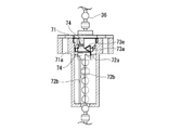
- FIG. 8 is an exploded view of the locking portion 7.
- the locking portion 7 includes a rotor 71, a cylindrical portion 72, and a knock cam 73.
- the rotor 71 is a cylindrical ring member provided with a through hole (not shown) on the central axis, and a ball chain 63 is inserted through the through hole.
- a ball chain 63 is inserted through the through hole.
- three convex portions 71a are formed at equal intervals. As shown in FIG. 8, the convex portion 71 a is provided so that a substantially triangular flat plate protrudes from the outer peripheral surface of the rotor 71.
- the convex portion 71a has a triangular shape having a first side 71b, a second side 71d, and a third side 71e.
- the first side 71 b is a side that is parallel to the axial direction of the rotor 71 (the direction in which the ball chain 63 extends) and is substantially equal to the height of the rotor 71.
- the upper side connecting the both ends of the first side 71b and the apex 71c located at the approximate center in the height direction of the rotor 71 is defined as a second side 71d, and the lower side is defined as a third side 71e.
- the rotor 71 is sandwiched between a pair of retaining rings 74 provided at the top and bottom.
- the pair of retaining rings 74 and 74 are fixed to the ball chain 63 in contact with the upper surface or the lower surface of the rotor 71. Therefore, the rotor 71 sandwiched between the pair of retaining rings 74 and 74 is configured to be immovable in the longitudinal axis direction with respect to the ball chain 63 and to be rotatable about the ball chain 63.
- the cylinder part 72 is a cylinder member having an insertion hole 72a penetrating in the vertical direction, and the upper end part has a large diameter part 72c thicker than the lower end part.
- the insertion hole 72a has an opening area through which the rotor 71 and the pair of retaining rings 74, 74 can be inserted, and the opening area is reduced in diameter at the lower end 72d.
- a guide groove 72b extending in the longitudinal axis direction from the lower end portion of the cylindrical portion 72 to the vicinity of the lower end portion of the large diameter portion 72c is formed on the inner peripheral surface of the insertion hole 72a.
- the guide groove 72b is dimensioned so that the convex portion 71a can slide, and is formed in three places in the insertion hole 72a.
- Each guide groove 72b has a first inclined surface 72e and a first vertical surface 72f at the upper end.
- the knock cam 73 has a lid portion 73b and a knock cam portion 73c.
- the lid 73b is provided with an opening 73d through which the ball chain 63 can be inserted at the center of a substantially disk-shaped member.
- a fitting projection 73f is provided on the lower surface of the lid portion 73b.
- the knock cam portion 73c is provided at the center portion of the lower surface of the lid portion 73b so as to protrude downward.
- the knock cam portion 73c is provided around the opening 73d of the lid portion 73b so as to be along the inner periphery of the insertion hole 72a while being inserted into the insertion hole 72a, and has a second inclined surface 73a and a second vertical surface 73e at the lower end portion. Is formed.
- the locking portion 7 inserts the rotor 71 and a pair of retaining rings 74, 74 attached to the ball chain 63 into the insertion hole 72a from above the cylindrical portion 72, and the knock cam portion 73c is inserted. It inserts in the insertion hole 72a.
- the lid portion 73 b is fixed to the cylindrical portion 72 by fitting the fitting projection 73 f into an engaging hole 72 g provided on the upper surface of the cylindrical portion 72.
- the lid portion 73b is fixed to the cylinder portion 72 so as not to rotate.
- the first inclined surface 72e of the cylindrical portion 72 and the second inclined surface 73a of the lid portion 73b are provided so as to be shifted in the circumferential direction.
- the ball chain 63 is provided to be movable in the longitudinal axis direction (vertical direction in FIG. 9A) in the insertion hole 72a.
- the rotor 71 and the pair of retaining rings 74, 74 are provided in the insertion hole 72a so as to be movable in the longitudinal axis direction between the bottom part of the lower end of the insertion hole 72a and the knock cam part 73c as the ball chain 63 moves. It has been.
- FIGS. 8 to 13B show the operation of the knock mechanism of the locking portion 7 and the operation of the valve portion 5 corresponding to the operation of the locking portion 7.
- the locking portion 7 can keep the flapper 52 in a valve open state or a valve closed state by an operation of moving the ball chain 63 by a predetermined distance.
- the flush toilet 1 has washing water supply means 9.
- the manual valve operating unit 81 is configured to be able to manually operate the cleaning water supply means 9 in order to allow the cleaning water to flow through the toilet bowl 3 and the drain pipe when there is no power supply such as during a power failure.
- the manual valve operation unit 81 is provided above the toilet body 2.
- the washing water supply means 9 and the manual valve operation unit 81 are known devices and are schematically shown in FIG.
- the user manually rotates the upper end portion 82 of the manual valve operation unit 81 around the longitudinal axis (in the direction of arrow D shown in FIG. 7), so that the cleaning water is supplied from the cleaning water supply means 9 to the toilet bowl 3. .
- the manual valve operation unit 81 and the opening / closing operation unit 66 are disposed adjacent to each other.
- the gripping portion 63 d has an opening at the center and can be fitted onto the rod-shaped upper end portion 82.
- the grip portion 63d also functions as an operation lever (grip portion) of the manual valve operation portion 81.
- the gripping portion 63d is fitted to the upper end portion 82 and the gripping portion 63d is rotated in the direction of arrow D. Note that the grip portion 63d is disposed in a state of being fitted to the upper end portion 82 in normal times.
- the upper lid 21 that can be opened and closed is provided on the upper surface of the back side of the toilet body 2, and the manual valve operation portion 81 and the opening and closing operation portion 66 are covered with the upper lid 21.
- FIG. 14 shows the operation of the valve unit 5 and the flow of washing water when washing the flush toilet 1 at the time of a power failure.
- the flapper 52 is in a valve open state as shown in FIG.
- the user opens the upper lid 21 and manually operates the manual valve operation unit 81 and the opening / closing operation unit 66.
- the ball chain 63 is temporarily locked by the knock mechanism of the locking portion 7 so as not to be pulled further. Is done. The user can feel that the gripper 63d feels a click and recognizes that the flapper 52 is closed. Further, since the ball chain 63 is locked to the locking portion 7, even when the user releases his / her hand from the gripping portion 63d, the valve closing state of the flapper 52 is maintained.
- the user visually confirms that the required amount of washing water has accumulated in the toilet bowl 3.
- the wash water overflows from the upper part of the toilet bowl 3 when the amount of stored water is excessive.
- the urging member 55 acts to prevent the amount of water stored in the toilet bowl 3 from becoming excessive.
- the head pressure on the flapper 52 by the washing water when the washing water reaches the predetermined water level of the toilet bowl 3 is measured in advance. Based on the measurement result of the water head pressure, when the water head pressure with respect to the flapper 52 becomes a predetermined value or more, the urging member 55 is elastically deformed so that the lever 62 is slightly rotated in the direction in which the flapper 52 is opened. The elastic coefficient of the urging member 55 is set. For this reason, a gap is formed between the inner wall of the toilet drainage path 4 and the flapper 52 so that, for example, a maximum of 12 liters / minute of washing water flows.
- the valve portion 5 is provided in the toilet drainage path 4, the position of the drain pipe provided in the installation location of the flush toilet 1 is provided on the floor (floor It is not necessary to change the configuration of the valve unit 5 even if it is provided on the wall (drainage toilet) or on the floor (floor drainage toilet). Therefore, there are many parts that can be shared by the floor drainage toilet and the floor drainage toilet, and versatility can be improved.
- the resin valve part main body 42 and the flapper 52 can be provided in a part of the toilet drainage path 4. Therefore, the valve part 5 can be provided in the toilet drainage path 4 which was difficult to provide in the conventional flush toilet.
- the valve body 42 is an integrally formed member, the toilet drainage path 4 (drainage pipe) has no joints between the members. Therefore, it is possible to prevent sewage and filth from adhering to the toilet drainage path 4.
- the rotating shaft 51, the rotating shaft 51, and the flapper are connected to the enlarged portion 42d of the toilet drainage path 4 (the top 4c of the toilet drainage path 4) where sewage and filth are difficult to reach during drainage.
- the connection part 5c with 52 is provided. For this reason, it can prevent that sewage and filth adhere to between connection parts 5c.
- the enlarged portion 42d is formed such that the upper part of the pipe line is larger on the downstream side than the upstream side, so that the enlarged portion 42d has sewage and filth at the time of drainage. Hard to reach. Since the connecting portion 5c between the rotation shaft 51 and the flapper 52 is provided in such an enlarged portion 42d, it is possible to prevent sewage and dirt from adhering between the rotation shaft and the connection portion of the flapper. it can.
- a gap S is formed between the inner wall of the toilet drainage path 4 (enlarged portion 42d) and the peripheral portion 53b of the flapper 52 with the flapper 52 opened.
- the siphon effect can be enhanced when draining the cleaning water, and the flow of the draining water can be easily controlled.
- the downstream end part 42j of the expansion part 42d is formed so as to protrude outward from the virtual flow path T of the flowing water pipe part 42a, the valve part 5 is provided in the toilet drainage path 4. Even so, it is possible to obtain a sufficient siphon effect when the cleaning water is drained.
- valve portion may be provided with a seal portion (not shown) at the peripheral portion 53b of the surface where the flapper 52 faces the inner wall of the toilet drainage path 4 when the valve is opened.
- a seal portion (not shown) at the peripheral portion 53b of the surface where the flapper 52 faces the inner wall of the toilet drainage path 4 when the valve is opened.
- valve body 42 may be provided in the toilet drainage path.
- the valve body is provided between the water reservoir and the drain socket, provided in the region of the top and the lower part from the middle of the ascending part, and flowing water that curves at a position including a part of the ascending part and the top and the lower part.
- the structure in which a pipe part is formed may be sufficient.
- the long member is not limited to the ball chain, and may be a long member having such a strength that the rotating shaft is rotated by pulling from the outside of the toilet body, for example, a wire, a chain, or the like. May be.
- the number of the protrusions 71a and the guide grooves 72b is not limited to three.
- the locking portion 7 has a knock mechanism
- the locking portion is not limited to this structure.
- a configuration in which a hook capable of engaging and disengaging the ball chain is provided in the vicinity of the operation unit and the rotation shaft, and the ball chain is pulled and locked to the hook may be employed.
- the locking portion 7 is provided on the upper side of the toilet body 2 where the gripping portion 63d of the ball chain 63 is disposed, but the locking portion 7 is provided at an arbitrary position on the path of the long member. It only has to be done.
- locking part 7 is not an essential structure.
- the example which provides the urging member 55 was shown, but the urging member 55 is not an essential configuration.
- the example which used the coil spring as the biasing member 55 was shown in this embodiment, the kind of spring is not ask
- connection portion 5c between the flapper 52 and the rotating shaft 51 can be provided in a region that does not interfere with the flowing water region of the toilet drainage path 4, so that sewage and filth at the time of running water to the connecting portion 5c are provided. Can be prevented.
- the enlarged part 42d in the flowing water pipe part 42a was shown, the enlarged part is not an essential structure in order to open and close the flow path of the toilet drainage path 4 in a non-energized state.
- step portion 42e is provided in the lower portion of the water flow pipe portion 42a in the present embodiment.
- step portion 42e is not an essential configuration, and the flapper can stop water contact with the inner wall of the water flow pipe portion 42a. I just need it.
- the installation position of the opening / closing operation unit 66 is not limited to the upper part.
- the side of the toilet body 2 may be used.
- the guide member 64 may form a long member guide path according to the installation position of the opening / closing operation unit 66.
- the guide member 64 shown in the present embodiment is merely an example, and may be any member that can guide the path of the long member, such as a cylindrical member, and can protect the lever and the long member in a protective manner.
Landscapes
- Engineering & Computer Science (AREA)
- General Engineering & Computer Science (AREA)
- Health & Medical Sciences (AREA)
- Public Health (AREA)
- Life Sciences & Earth Sciences (AREA)
- Hydrology & Water Resources (AREA)
- Water Supply & Treatment (AREA)
- Mechanical Engineering (AREA)
- Epidemiology (AREA)
- Physics & Mathematics (AREA)
- Electromagnetism (AREA)
- Sanitary Device For Flush Toilet (AREA)
Abstract
本発明の水洗式便器は、便鉢と、前記便鉢及び排水ソケットと連通し、前記便鉢から洗浄水が流入する便器排水経路と、前記便器排水経路に設けられた回動軸及び前記回動軸に接続され前記回動軸周りに回動可能に設けられたフラッパを有し、前記便器排水経路を開閉する弁部と、を備えることを特徴とする。
Description
本発明は、水洗式便器に関する。本願は、2015年8月31日に、日本国に出願された特願2015-171217号に基づき優先権を主張し、その内容をここに援用する。
電力により洗浄水供給手段を駆動する従来の水洗式便器において、停電が発生すると、洗浄水供給手段が稼働できずに便器洗浄が行えない場合がある。この課題に対し、例えば、特許文献1には、停電時に電気的な駆動によって洗浄水を供給し、手動操作、非常用電源、及び機械要素のいずれかにより排水ソケット内の弁を開閉し、ボウル部に水を貯めて洗浄を行う水洗大便器が開示されている。
特許文献1に開示の水洗大便器では、電磁弁を開閉するために電源が必要となる。このため、例えば、落雷による停電等、停電時に電気系統の故障が生じると、電磁弁が開閉できずに洗浄できないという課題があった。また、排水ソケットは、床排水便器(Sトラップ)及び床上排水便器(Pトラップ)によって形状が異なる。特許文献1に開示の水洗大便器では、排水ソケットに開閉弁が設けられるため、床排水便器及び床上排水便器の排水ソケットにそれぞれに対応する開閉弁を設ける必要があるという課題があった。
上記事情を踏まえ、本発明は、床排水便器及び床上排水便器に共用可能な部品が多く汎用性を高めた水洗式便器を提供することを目的とする。
本発明の第一の態様に係る水洗式便器は、便鉢と、前記便鉢及び排水ソケットと連通し、前記便鉢から洗浄水が流入する便器排水経路と、前記便器排水経路に設けられた回動軸及び前記回動軸に接続され前記回動軸周りに回動可能に設けられたフラッパを有し、前記便器排水経路を開閉する弁部と、を備えることを特徴とする。
この発明によれば、便器排水経路に弁部が設けられるので、水洗式便器の設置箇所に設けられている排管の位置が床に設けられている場合(床排水便器)でも、壁に設けられている場合(床上排水便器)でも、弁部の構成を変更する必要がない。したがって、床排水便器及び床上排水便器に共用可能な部品が多く、汎用性を高めることができる水洗式便器を提供できる。
本発明の第二の態様は、第一の態様に係る水洗式便器において前記弁部は、前記便器排水経路の一部を構成する弁部本体を備え、前記回動軸及び前記フラッパは前記弁部本体に設けられ、前記弁部本体及び前記フラッパは樹脂製であってもよい。
この発明によれば、便器排水経路の一部に樹脂製の弁部本体及びフラッパを設けることができる。したがって、従来の水洗式便器では設けることが難しかった便器排水経路に弁部を設けることができる。
本発明の第三の態様は、第二の態様に係る水洗式便器において、前記弁部本体は一体成形部材であってもよい。
この発明によれば、弁部本体が一体成形部材であるため、排水管路に部材の継ぎ目等が無い。そのため、排水管路に汚水や汚物が付着することを防ぐことができる。
本発明の第四の態様は、第一から第三のいずれかの態様に係る水洗式便器において、前記回動軸と前記フラッパとの接続部及び前記回動軸が前記便器排水経路の頂部に設けられていてもよい。
この発明によれば、排水時に汚水や汚物が到達し難い便器排水経路の頂部に回動軸及び回動軸とフラッパとの接続部が設けられている。このため、回動軸とフラッパの接続部との間等に汚水や汚物が付着することを防ぐことができる。
本発明の第五の態様は、第二から第四のいずれかの態様に係る水洗式便器において、前記弁部本体の前記洗浄水が流れる管路には、上部が上流側より少なくとも高さ方向に拡大する拡大部が設けられ、前記拡大部に前記回動軸と前記フラッパとの接続部及び前記回動軸が設けられていてもよい。
この発明によれば、拡大部は、管路の上部が下流側において上流側よりも大きくなるように形成されているので、排水時に拡大部には汚水や汚物が到達し難い。このような拡大部に回動軸とフラッパとの接続部が設けられているので、回動軸とフラッパとの接続部の間等に汚水や汚物が付着することを防ぐことができる。
本発明の第六の態様は、第一から第五のいずれかの態様に係る水洗式便器において、前記弁部は、前記フラッパが開弁した状態で、前記便器排水経路の内壁と前記フラッパの周縁部との間に隙間が形成されるように構成されてもよい。
この発明によれば、フラッパが開弁した状態で便器排水経路の内壁とフラッパの周縁部との間に隙間が形成されることにより、洗浄水の排水時にサイフォンの効果を高めることができ、洗浄時の排水の流れを制御しやすい。
本発明の第七の態様は、第一から第五のいずれかの態様に係る水洗式便器において、前記弁部は、前記フラッパが開弁した状態で、前記便器排水経路の内壁と対向する前記フラッパの周縁部との間を水密に保つように構成されていてもよい。
この発明によれば、フラッパの周縁部と便器排水経路の内壁との間を水密に保ち、フラッパと便器排水経路の内壁との間に排水が流入することを防いで、便器排水経路の内壁とフラッパとの間に汚水や汚物が付着することを防ぐことができる。
本発明の水洗式便器によれば、停電時に電力を用いずに便鉢の洗浄が可能となり、且つ、床排水便器及び床上排水便器に共用可能な部品が多く汎用性を高めることができる。
本発明の一実施形態に係る水洗式便器について説明する。図1及び図2は本実施形態に係る水洗式便器1の断面図であり、図1には弁部の開弁状態を示し、図2には弁部の閉弁状態を示している。
本実施形態に係る水洗式便器1は、図1及び図2に示すように、所謂サイフォン洗い落とし形式の洋風便器であり、便器本体2と、便鉢3と、便器排水経路4と、弁部5と、排水ソケット10と、便座11とを備える。便器本体2と、便鉢3と、便器排水経路4の一部とは陶磁器で一体に形成されている。便器排水経路4と、排水ソケット10とは、排水管路を構成する。
以下の説明において、便座11に着座する使用者の顔が向く方向を前方とし、便座11に着座する使用者の背中が向く方向を後方とする。
以下の説明において、便座11に着座する使用者の顔が向く方向を前方とし、便座11に着座する使用者の背中が向く方向を後方とする。
図1に示すように、便器排水経路4は、便鉢3の下部の開口と連通し、下流側で排水ソケット10に連通している。便器排水経路4は、洗浄水の流路の上流から順に、溜水部4aと、上昇部4bと、頂部4cと、下降部4dとを有する。
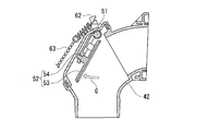
便器排水経路4には、弁部5が設けられている。具体的には、弁部5は、溜水部4aと排水ソケット10との間であり、頂部4cに位置する。図3に弁部5の側面図を示す。図4に開弁状態である弁部5の断面図を示す。図5に閉弁状態である弁部5の断面図を示す。弁部5は、弁部本体42と、回動軸51と、フラッパ52とを備える。
弁部本体42は樹脂製の一体成形部材である。図2に示すように、弁部本体42は、陶磁器製の上昇部4bの下流端部とシール材44を間に挟んで水密に接合されている。図3に示すように、弁部本体42は、流水管部42aを備える。流水管部42aは、上昇部4bとの接合部42bと排水ソケット10と接続される下端開口部42cとの間で下方に向かって湾曲する管路を形成している。流水管部42aは便器排水経路4の一部を構成する。
図4に示すように、流水管部42aの湾曲部分の上部(便器排水経路4の頂部4c)には、接合部42b側(上流側)よりも管路が広がる拡大部42dを有する。拡大部42dは、流水時にも空気が残る空気溜まり部となる。拡大部42dは、後述する回動軸及びフラッパが配置可能な程度の寸法で形成されている。
流水管部42aの湾曲部分の下部にも接合部42b側(上流側)よりも管路が広がるような段部42eが設けられている。
回動軸51は便器排水経路4の頂部4cに設けられている。具体的には、回動軸51は、流水管部42aの湾曲部分の上部に設けられている。回動軸51は、流路に対して直交する方向に延び、且つ、両端部が弁部本体42に貫通するように取り付けられている。回動軸51は、拡大部42d内の上流側に収容されている。
フラッパ52は、便器排水経路4の頂部4cに設けられている。具体的には、フラッパ52は、一端部が回動軸51に回動可能に取り付けられている。したがって、回動軸51とフラッパ52との接続部5cは拡大部42d(空気溜まり部)に設けられている。フラッパ52は、流水管部(管路)42a内で流路に対して略直交する方向に閉弁可能に設けられている。
フラッパ52は、平板部53と、支持部54とを備える。平板部53は、流水管部42aの流路を塞ぎ、且つ、流水管部42a内で回動軸51周りに回動可能な程度の面積を有する。支持部54は、平板部53と接続され、一端部が回動軸51に回動可能に係合されている。回動軸51から離れた位置にある平板部53の端部53aは回動方向に立ち上がるように湾曲しており、図2に示すように、閉弁時に端部53aが段部42eに当接して流路を封止できるように構成されている。
図1及び図4に示すように、平板部53は、フラッパ52が開弁した状態において、流水管部42aの上流側の内壁42gに沿うように配置されるように支持部54に支持されている。したがって、フラッパ52が開弁した状態において、拡大部42dにおける流水管部42aの内壁42fと平板部53とは離間している。図4に示すように、弁部5は、フラッパ52が開弁した状態では、弁部本体42の内壁42fと、フラッパ52の周縁部53bの間に隙間Sが形成されるように構成されている。
図4に示すように、拡大部42dの下流端部42jは、流水管部42aの下端開口部42c側の内壁42kよりも外方に流路が拡大するように形成されている。すなわち、拡大部42dの下流端部42jは、流水管部42aの上流側の内壁42gと下端開口部42c側の内壁42kとを結ぶ仮想流路Tよりも外側に突出し、流路が拡大している。
回転動作部6によりフラッパ52の開閉動作が行われる。回転動作部6は、弁部本体42の外面側における拡大部42dの上方に設けられている。図3に示すように、回転動作部6は、回動バネ61と、レバー62と、玉鎖(長軸部材)63と、ガイド部材64と、係止部7(図2参照)とを備える。
回動バネ61は、ねじりバネであり、弁部本体42の外面に突出する回動軸51の端部にコイル部分が外挿され、第一端部61aが弁部本体42に設けられたバネ係止部43に当接し、第二端部61bがレバー62に係止されている。バネ係止部43は、弁部本体42の外面における回動軸51が配置される部分に、回動軸51を中心とする仮想円の接線に沿う壁が形成されている。この壁に第一端部61aが当接することにより、回動バネ61の回転が規制される。
レバー62は、回動軸51と直交する方向に突出し、フラッパ52の支持部54と係合されている。レバー62は回動軸51を中心として回動可能である。図4及び図5に示すように、レバー62はフラッパ52の支持部54と係合しているので、レバー62の回動に伴ってフラッパ52が回動する。
レバー62は、回動バネ61の第二端部62bにより、図3に矢印Aで示す方向に付勢されている。レバー62の突出端部62aには、付勢部材55を介して玉鎖(長軸部材)63が接続されている。
玉鎖63は、第一端部63aがレバー62側と接続され、第二端部63bは便器本体2の外方まで延出して設けられる長尺な部材である。玉鎖63の第二端部63bにはリング6cと把持部63dとが連続して設けられている。玉鎖63の第二端部63bは、開閉操作部(操作部)66に配置される。
ガイド部材64は、弁部本体42の外面側における拡大部42dの上方に設けられている。図6にガイド部材64の斜視図を示す。ガイド部材64は、樹脂製の成形部材であり、レバー62と、付勢部材55と、玉鎖63とが収容される部材である。ガイド部材64は、玉鎖63の経路をガイドする機能と、玉鎖63と、付勢部材55と、レバー62とが、外力により脱落することを防ぐ機能とを備える。
ガイド部材64は、側壁64aに上ガイド64bと下ガイド64cとが突出して設けられている。ガイド部材64の上端部にはレバー収容部64dを備える。図5に示すように、ガイド部材64は、ネジ64fがネジ溝64e及び弁部本体42のネジ止め部42hに挿入されることにより弁部本体42に固定される。上ガイド64bの側壁64aからの突出量は、下ガイド64cの突出量より大きい。玉鎖63は、上ガイド64bと下ガイド64cとの間及び側壁64aとネジ止め部42hとの間に収容される。
ガイド部材64の下端部64hは、便器本体2の外方に設けられる開閉操作部66(図1及び図7参照)が位置する方向に向かって湾曲する。本実施形態では、開閉操作部66は、便器本体2の上部に設けられ、玉鎖63の第二端部63bは便器本体2の上方に延びるように配置されるので、ガイド部材64の下端部64hは上方に向かって湾曲している。このように、ガイド部材64は、玉鎖63がフラッパ52を回動させるために移動する方向と、玉鎖63の第二端部63bが、便器本体2の外方で牽引される方向とに、玉鎖63の経路を案内する。
付勢部材55は、コイルバネである。付勢部材55は、閉弁時に、フラッパ52が便器排水経路4を閉じた状態を保つようにフラッパ52を付勢する。付勢部材55は、フラッパ52の閉弁時に、洗浄水の溜め水よるフラッパ52に対する水頭圧が所定値以上となった場合にフラッパ52が回動して便器排水経路4の下側の内壁42i及び段部42eとフラッパ52との間に流水可能な隙間を形成するように付勢力が設定されている。付勢部材55の付勢力については後述する。
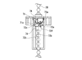
係止部7は、玉鎖63を所定の牽引位置に保持するノック機構を有する。係止部7は、玉鎖63の把持部63dが配置される便器本体2の上側に設けられている。図8は係止部7の分解図である。係止部7は、回転子71と、筒部72と、ノックカム73とを有する。
回転子71は、中心軸上に不図示の貫通孔が設けられた円柱状のリング部材であり、貫通孔に玉鎖63が挿通されている。回転子71の外周面には、等間隔に3つの凸部71aが形成されている。図8に示すように、凸部71aは、略三角形状の平板が回転子71の外周面に突出するように設けられている。凸部71aは、第一辺71bと、第二辺71dと第三辺71eとを有する三角形状である。第一辺71bは、回転子71の軸方向(玉鎖63が延びる方向)に平行であり且つ回転子71の高さと略等しい辺である。第一辺71bの両端と、回転子71の高さ方向の略中央部に位置する頂点71cと結んだ上側の辺を第二辺71dとし、下側の辺を第三辺71eとする。
回転子71は、上下に設けられた一対の止め輪74、74により挟まれている。一対の止め輪74、74は、回転子71の上面又は下面と当接した状態で玉鎖63に固定されている。そのため、一対の止め輪74、74に挟まれた回転子71は、玉鎖63に対して長手軸方向に移動不能且つ玉鎖63を中心として回転可能に構成されている。
筒部72は、上下方向に貫通する挿通孔72aを有する筒部材であり、上端部は下端部より厚い大径部72cを有する。挿通孔72aは、回転子71及び一対の止め輪74、74が挿通可能な開口面積を有し、下端部72dで開口面積が縮径している。図8及び図9Aに示すように、挿通孔72aの内周面には、筒部72の下端部から大径部72cの下端部近傍まで長手軸方向に延びるガイド溝72bが形成されている。ガイド溝72bは凸部71aがスライド可能な寸法で、挿通孔72aに3箇所形成されている。各ガイド溝72bの上端には第一傾斜面72eと第一垂直面72fとを有する。
ノックカム73は、蓋部73bと、ノックカム部73cとを有する。蓋部73bは略円盤状の部材の中央部に玉鎖63が挿通可能な開口73dが設けられている。蓋部73bの下面には、嵌合突起73fが設けられている。
ノックカム部73cは、蓋部73bの下面の中央部に下方に突出するように設けられている。ノックカム部73cは、挿通孔72aに挿入された状態で挿通孔72aの内周に沿うように蓋部73bの開口73d周りに設けられ、下端部に第二傾斜面73aと第二垂直面73eとが形成されている。
図9Aに示すように、係止部7は、玉鎖63に取り付けられた回転子71及び一対の止め輪74、74を筒部72の上方から挿通孔72a内に挿入し、ノックカム部73cを挿通孔72aに挿入する。蓋部73bは、嵌合突起73fが筒部72の上面に設けられた係合穴72gに嵌合されることにより筒部72に固定される。蓋部73bは筒部72に対して回転不能に固定されている。このとき、筒部72の第一傾斜面72eと蓋部73bの第二傾斜面73aとは、周方向にずれて位置するように設けられている。玉鎖63は挿通孔72a内を長手軸方向(図9Aの上下方向)に移動可能に設けられている。回転子71及び一対の止め輪74、74は、玉鎖63の移動に伴って、挿通孔72a内を挿通孔72aの下端の底部とノックカム部73cとの間を長手軸方向に移動可能に設けられている。
次に、係止部7のノック機構の動作について図8から図13Bを用いて説明する。図9Aから図13Bには、係止部7の動作、及び係止部7の動作に対応する弁部5の動作を示す。
図9Bに示すように、フラッパ52が開弁状態にあるとき、係止部7では図9Aに示すように、回転子71は挿通孔72aの下端に位置する。
フラッパ52を手動で閉弁させる場合、使用者が玉鎖63を引くと、図10Aに示すように、回転子71が蓋部73b側に引き上げられて挿通孔72aの上部に到達する。このとき、図10Bに示すように、フラッパ52は矢印F方向に回動する。回転子71の凸部71aがガイド溝72b内を摺動する間は、回転子71の回転は規制されている。しかし、回転子71が挿通孔72aの上部に引き上げられて、回転子71の凸部71aがガイド溝72bから外れると、回転子71は回転可能となる。玉鎖63が牽引された状態で、凸部71aの第二辺71dがノックカム部73cの第二傾斜面73aに当接するので、回転子71が右方向(図10Aの矢印E方向)に回転する。続いて、図11Aに示すように、凸部71aの第一辺71bがノックカム部73cの第二垂直面73eに当接して回転子71の回転が止まる。この状態では、玉鎖63は上方向への移動が規制されるので、使用者は、玉鎖63を所定量牽引したことを認識できて、玉鎖63の牽引を止める。
玉鎖63に引き上げられる力が解除されたら、図12Aに示すように、回転子71が下降し、凸部71aが筒部72の第一傾斜面72eに当接して、第一傾斜面72eに沿って移動して回転子71が右方向に回転する。第一辺71bが筒部72の第一垂直面72fに当接すると回転子71の回転が規制され、玉鎖63は係止される。この結果、フラッパ52は、図12Bに示すように閉弁状態が保たれる。なお、図12A及び図12Bに示す状態では、玉鎖63には回動バネ61からの牽引力が作用している。
次に、フラッパ52を開弁するときは、使用者が玉鎖63の把持部63dを少し牽引して離すと、図13Aに示すように、回転子71が一旦上側に移動して、筒部72の第一垂直面72fによる回転子71の回転規制が解除されて回転子71が右回転し、隣のガイド溝72bに凸部71aが入る。このとき、玉鎖63には回動バネ61からの牽引力が作用しているため、回転子71は挿通孔72aの下部まで移動する。この結果、図13Bに示すように、フラッパ52が矢印G方向に回動して開弁状態となる。
以上の構成により、係止部7は、玉鎖63を所定距離移動させる操作により、フラッパ52を開弁状態あるいは閉弁状態に保つことができる。
水洗式便器1は洗浄水供給手段9を有している。手動弁操作部81は、停電時等の無通電時に便鉢3及び排水管路に洗浄水を流すために、洗浄水供給手段9を手動で操作可能に構成されている。手動弁操作部81は便器本体2の上方に設けられている。洗浄水供給手段9及び手動弁操作部81は公知の装置であり、図1では模式的に示している。使用者が手動弁操作部81の上端部82を、手動で長手軸周り(図7に示す矢印D方向)に回転操作することにより洗浄水が洗浄水供給手段9から便鉢3へ供給される。
図7に示すように、手動弁操作部81と、開閉操作部66とは、隣接して配置されている。ここで、図5及び図7に示すように、把持部63dは、中央に開口が形成されており、棒状の上端部82に外嵌可能である。把持部63dは、手動弁操作部81の操作レバー(把持部)としての機能を兼ねる。手動弁操作部81の上端部82を回転操作する際は、把持部63dを上端部82に嵌合させて把持部63dを矢印D方向に回転させる。なお、平常時、把持部63dは上端部82に嵌合させた状態で配置されている。
図1に示すように、便器本体2の後ろ側の上面には開閉可能な上蓋21が設けられており、手動弁操作部81及び開閉操作部66は上蓋21で覆われている。
次に、本実施形態に係る水洗式便器1の停電時の動作について説明する。図14は、停電時に水洗式便器1を洗浄する際の、弁部5の動作及び洗浄水の流れを示している。
平常時(通電時)、フラッパ52は図4に示すように開弁状態である。停電時に便器の洗浄を行う場合、使用者は、上蓋21を開けて手動弁操作部81及び開閉操作部66を手動で操作する。
平常時(通電時)、フラッパ52は図4に示すように開弁状態である。停電時に便器の洗浄を行う場合、使用者は、上蓋21を開けて手動弁操作部81及び開閉操作部66を手動で操作する。
まず、使用者が、上端部82に嵌合するように配置された把持部63dを反時計回りに約180度回転させると、洗浄水供給手段9における洗浄水の供給が開始され、図14(A)に示すように便鉢3内に給水される。続いて、使用者が把持部63dを持ち上げて玉鎖63を上方に牽引すると、ガイド部材64の上ガイド64bの湾曲部64gに玉鎖63が当接しながら牽引される。その結果、レバー62が図5に示す矢印B方向に回動して、フラッパ52が矢印C方向に回動して閉弁状態となり貯水される。
このとき、平板部53の端部53aが段部42eに当接した閉弁状態となったときに、係止部7のノック機構により、玉鎖63はこれ以上牽引されないように一時的にロックされる。使用者は、把持部63dからクリック感を感じてフラッパ52が閉弁状態となったことを認識できる。また、玉鎖63は係止部7に係止されるので、使用者が把持部63dから手を離しても、フラッパ52の閉弁状態は維持される。
使用者は、便鉢3内に必要な量の洗浄水が溜まるのを目視で確認する。便鉢3内に洗浄水を貯めるとき、例えば、使用者が水洗式便器1から離れた場合等、貯水量が過剰となると便鉢3の上部から洗浄水が溢れる。便鉢3内の貯水量が過剰となることを防ぐために、付勢部材55が作用する。
フラッパ52の閉弁時に、洗浄水が便鉢3の所定水位となったときの洗浄水によるフラッパ52に対する水頭圧を予め測定する。水頭圧の測定結果に基づき、フラッパ52に対する水頭圧が所定値以上となった場合に、付勢部材55が弾性変形してレバー62がフラッパ52を開弁させる方向にわずかに回動するように、付勢部材55の弾性係数が設定されている。そのため、便器排水経路4の内壁とフラッパ52との間に、例えば、最大12リットル/分程度の洗浄水が流れる程度の隙間が形成される。このような付勢部材55が設けられることにより、便鉢3の貯水量が所定量以上となった場合は、洗浄水が少しずつ便器排水経路4のフラッパ52よりも下流側に排水され、便鉢3の上部から洗浄水が溢れるのを防ぐことができる。
図14(B)に示すように、便鉢3に十分な貯水量が得られたら、使用者は、把持部63dを再び持ち上げて玉鎖63を牽引する。このとき、上述した係止部7のノック機構により、回転子71のガイド溝72bとの係合が解除されて右側に回転し、玉鎖63が回動バネ61に引っ張られて、回転子71も筒部72の最下部まで下降する。この結果、フラッパ52が開弁状態となる。したがって、玉鎖63を少し引くだけで玉鎖63のロック状態が解除されてフラッパ52を開弁状態に戻すことができる。
フラッパ52が開弁状態に戻ると、図14(C)に示すように、平常時と同様に、便器排水経路4に洗浄水が流入してサイフォン現象が生じて、便鉢3から洗浄水が排水管側に流れる。使用者は、手動弁操作部81の上端部82に嵌合させた把持部63dを時計回りに約180度回して、洗浄水供給手段9における洗浄水の供給を止めると、図14(D)に示すように、便器の洗浄が完了する。使用者が、上蓋21を閉める。
本実施形態に係る水洗式便器1は、便器排水経路4に弁部5が設けられるので、水洗式便器1の設置箇所に設けられている排管の位置が床に設けられている場合(床排水便器)でも、壁に設けられている場合(床上排水便器)でも、弁部5の構成を変更する必要がない。したがって、床排水便器及び床上排水便器に共用可能な部品が多く、汎用性を高めることができる。
本実施形態の水洗式便器1によれば、便器排水経路4の一部に樹脂製の弁部本体42及びフラッパ52を設けることができる。したがって、従来の水洗式便器では設けることが難しかった便器排水経路4に弁部5を設けることができる。
本実施形態の水洗式便器1によれば、弁部本体42が一体成形部材であるため、便器排水経路4(排水管路)に部材の継ぎ目等が無い。そのため、便器排水経路4に汚水や汚物が付着することを防ぐことができる。
本実施形態の水洗式便器1によれば、排水時に汚水や汚物が到達し難い便器排水経路4の拡大部42d(便器排水経路4の頂部4c)に回動軸51及び回動軸51とフラッパ52との接続部5cが設けられている。このため、接続部5cとの間等に汚水や汚物が付着することを防ぐことができる。
本実施形態の水洗式便器1によれば、拡大部42dは、管路の上部が下流側において上流側よりも大きくなるように形成されているので、排水時に拡大部42dには汚水や汚物が到達し難い。このような拡大部42dに回動軸51とフラッパ52との接続部5cが設けられているので、回動軸とフラッパの接続部との間等に汚水や汚物が付着することを防ぐことができる。
本実施形態の水洗式便器1によれば、フラッパ52が開弁した状態で便器排水経路4(拡大部42d)の内壁とフラッパ52の周縁部53bとの間に隙間Sが形成されることにより、洗浄水の排水時にサイフォンの効果を高めることができ、洗浄時の排水の流れを制御しやすい。また、拡大部42dの下流端部42jは、流水管部42aの仮想流路Tよりも外方に拡大するように突出して形成されているので、便器排水経路4に弁部5を設けた構成であっても、洗浄水の排水時に十分なサイフォンの効果を得ることができる。
以上、本発明の実施形態について図面を参照して詳述したが、具体的な構成はこの実施形態に限られるものではなく、本発明の要旨を逸脱しない範囲の設計変更等も含まれる。
また、上述の各実施形態及び各変形例において示した構成要素は適宜に組み合わせて構成することが可能である。
また、上述の各実施形態及び各変形例において示した構成要素は適宜に組み合わせて構成することが可能である。
例えば、弁部は、開弁時にフラッパ52が便器排水経路4の内壁と対向する面の周縁部53bにシール部(不図示)を設けてもよい。この構成によれば、開弁時にフラッパ52と便器排水経路4の内壁との間が水密に保たれて、フラッパ52と便器排水経路4の内壁との間に汚水や汚物が流入することを防ぐことができる。
本実施形態では、弁部本体42を頂部4c及び下降部4dに配置する例を示したが、弁部本体42は便器排水経路に設けられればよい。例えば、弁部本体を、溜水部と排水ソケットとの間であり、上昇部の途中から頂部及び下降部の領域に設け、上昇部の一部と頂部及び下降部を含む位置で湾曲する流水管部が形成される構成であってもよい。
長尺部材は、玉鎖に限定されず、便器本体の外方から牽引することにより回動軸を回転させる程度の強度を有する長尺な部材であればよく、例えば、ワイヤ、チェーン等であってもよい。
本実施形態では、係止部7に3つの凸部71a及び3つのガイド溝72bを設ける例を示したが、凸部71a及びガイド溝72bは複数あればよく、3つに限定されない。
本実施形態では、係止部7がノック機構を有する例を示したが、係止部はこの構造に限定されない。例えば、玉鎖が係脱可能なフックを、操作部近傍や回動軸の近傍に設け、玉鎖を牽引した状態でフックに係止する構成であってもよい。
本実施形態では、係止部7を玉鎖63の把持部63dが配置される便器本体2の上側に設ける構成としたが、係止部7は長尺部材の経路上の任意の位置に設けられればよい。
本実施形態では、係止部7を設ける例を示したが、係止部7は必須の構成ではない。
本実施形態では、付勢部材55を設ける例を示したが付勢部材55は必須の構成ではない。また、本実施形態では、付勢部材55としてコイルバネを使用した例を示したが、バネの種類は問わない。
本実施形態では、付勢部材55を設ける例を示したが付勢部材55は必須の構成ではない。また、本実施形態では、付勢部材55としてコイルバネを使用した例を示したが、バネの種類は問わない。
拡大部42dを設けることにより、便器排水経路4の流水領域と干渉しない領域にフラッパ52と回動軸51との接続部5cを設けることができるので、接続部5cへの流水時の汚水や汚物の付着を防ぐことができる。本実施形態では、流水管部42aに拡大部42dを設けた例を示したが、無通電状態で便器排水経路4の流路を開閉させるという目的においては、拡大部は必須の構成ではない。
本実施形態では、流水管部42aの下部に段部42eを設けた例を示したが、段部42eは必須の構成ではなく、フラッパが流水管部42aの内壁と当接して止水可能であればよい。
本実施形態では、開閉操作部66を便器本体2の上部に設ける例を示したが、開閉操作部66の設置位置は上部に限定されない。例えば、便器本体2の側方等であってもよい。このとき、ガイド部材64は、開閉操作部66の設置位置に応じて長尺部材のガイド経路を形成すればよい。
本実施形態で示したガイド部材64は、一例に過ぎず、例えば、筒部材等、長尺部材の経路をガイドし、且つ、レバー及び長尺部材を保護可能に収容できる部材であればよい。
1 水洗式便器
3 便鉢
4 便器排水経路
5 弁部
10 排水ソケット
42 弁部本体
42a 管路
42d 拡大部
42f 内壁
51 回動軸
52 フラッパ
53b 周縁部
5c 接続部
3 便鉢
4 便器排水経路
5 弁部
10 排水ソケット
42 弁部本体
42a 管路
42d 拡大部
42f 内壁
51 回動軸
52 フラッパ
53b 周縁部
5c 接続部
Claims (7)
- 便鉢と、
前記便鉢及び排水ソケットと連通し、前記便鉢から洗浄水が流入する便器排水経路と、
前記便器排水経路に設けられた回動軸及び前記回動軸に接続され前記回動軸周りに回動可能に設けられたフラッパを有し、前記便器排水経路を開閉する弁部と、
を備えることを特徴とする水洗式便器。 - 前記弁部は、前記便器排水経路の一部を構成する弁部本体を備え、
前記回動軸及び前記フラッパは前記弁部本体に設けられ、
前記弁部本体及び前記フラッパは樹脂製である
請求項1に記載の水洗式便器。 - 前記弁部本体は一体成形部材である
請求項2に記載の水洗式便器。 - 前記回動軸と前記フラッパとの接続部及び前記回動軸が前記便器排水経路の頂部に設けられている
請求項1から請求項3のいずれか一項に記載の水洗式便器。 - 前記弁部本体の前記洗浄水が流れる管路には、上部が上流側より少なくとも高さ方向に拡大する拡大部が設けられ、
前記拡大部に前記回動軸と前記フラッパとの接続部及び前記回動軸が設けられている
請求項2から請求項4のいずれか一項に記載の水洗式便器。 - 前記弁部は、前記フラッパが開弁した状態で、前記便器排水経路の内壁と前記フラッパの周縁部との間に隙間が形成されるように構成される
請求項1から請求項5のいずれか一項に記載の水洗式便器。 - 前記弁部は、前記フラッパが開弁した状態で、前記便器排水経路の内壁と対向する前記フラッパの周縁部との間を水密に保つように構成されている
請求項1から請求項5のいずれか一項に記載の水洗式便器。
Priority Applications (3)
| Application Number | Priority Date | Filing Date | Title |
|---|---|---|---|
| EP16841778.0A EP3346067A4 (en) | 2015-08-31 | 2016-08-29 | FLUSH |
| US15/755,545 US10392790B2 (en) | 2015-08-31 | 2016-08-29 | Flush toilet |
| CN201680048563.5A CN107923174B (zh) | 2015-08-31 | 2016-08-29 | 水洗式便器 |
Applications Claiming Priority (2)
| Application Number | Priority Date | Filing Date | Title |
|---|---|---|---|
| JP2015-171217 | 2015-08-31 | ||
| JP2015171217A JP6457357B2 (ja) | 2015-08-31 | 2015-08-31 | 水洗式便器 |
Publications (1)
| Publication Number | Publication Date |
|---|---|
| WO2017038746A1 true WO2017038746A1 (ja) | 2017-03-09 |
Family
ID=58187486
Family Applications (1)
| Application Number | Title | Priority Date | Filing Date |
|---|---|---|---|
| PCT/JP2016/075156 Ceased WO2017038746A1 (ja) | 2015-08-31 | 2016-08-29 | 水洗式便器 |
Country Status (6)
| Country | Link |
|---|---|
| US (1) | US10392790B2 (ja) |
| EP (1) | EP3346067A4 (ja) |
| JP (1) | JP6457357B2 (ja) |
| CN (1) | CN107923174B (ja) |
| TW (1) | TW201713830A (ja) |
| WO (1) | WO2017038746A1 (ja) |
Families Citing this family (5)
| Publication number | Priority date | Publication date | Assignee | Title |
|---|---|---|---|---|
| DE112019001701T5 (de) * | 2018-03-30 | 2020-12-10 | Lixil Corporation | Toilettenvorrichtung und Toilettensitzeinheit |
| US20220010537A1 (en) * | 2018-11-23 | 2022-01-13 | Erman USTA | A toilet waste water drain structure that saves water by eliminating the requirement for a reservoir |
| JP7180641B2 (ja) * | 2020-06-30 | 2022-11-30 | Toto株式会社 | 給水機構および水洗大便器 |
| US12181056B2 (en) | 2022-04-14 | 2024-12-31 | A Shane Alcorn | Passive backflow prevention apparatus and associated toilet system and method |
| CN116180853B (zh) * | 2023-01-17 | 2026-01-23 | 东莞市众隆泵业科技有限公司 | 马桶冲水控制方法及马桶冲刷水泵 |
Citations (3)
| Publication number | Priority date | Publication date | Assignee | Title |
|---|---|---|---|---|
| JP2000008464A (ja) * | 1998-06-25 | 2000-01-11 | Matsushita Electric Works Ltd | 水洗便器 |
| JP2012107490A (ja) * | 2010-10-29 | 2012-06-07 | Lixil Corp | トイレ装置 |
| US20130025039A1 (en) * | 2011-07-29 | 2013-01-31 | Armstrong Timothy D | Waste water unclogging system and method |
Family Cites Families (8)
| Publication number | Priority date | Publication date | Assignee | Title |
|---|---|---|---|---|
| DE480074C (de) * | 1929-07-26 | Asminde Pohl Geb Bruhn | Abtrittbecken mit einer Rueckschlagklappe hinter dem Wasserverschluss, bei dem die Klappe durch einen leicht loesbaren Deckel im Ablaufstutzen von aussen zugaenglich ist | |
| CN2108130U (zh) * | 1992-01-03 | 1992-06-24 | 浙江建筑卫生陶瓷厂 | 一种坐便器 |
| AT403071B (de) * | 1996-04-30 | 1997-11-25 | Walter Dipl Ing Kuprian | Wasserklosett |
| US7284286B1 (en) | 2006-09-22 | 2007-10-23 | Kohler Co. | Toilet discharge valve |
| KR20090113201A (ko) * | 2008-04-25 | 2009-10-29 | 김영곤 | 물넘이 방지턱을 수평으로 개선한 악취 제거 및 초절수형 양변기 |
| CN101705714B (zh) * | 2009-11-10 | 2011-06-22 | 王宏勋 | 一种节水座便器 |
| JP6120055B2 (ja) | 2012-03-28 | 2017-04-26 | Toto株式会社 | 水洗大便器 |
| CN102966163B (zh) * | 2012-11-30 | 2015-01-21 | 广东慧信环保有限公司 | 一种杠杆阀马桶 |
-
2015
- 2015-08-31 JP JP2015171217A patent/JP6457357B2/ja active Active
-
2016
- 2016-08-29 CN CN201680048563.5A patent/CN107923174B/zh active Active
- 2016-08-29 WO PCT/JP2016/075156 patent/WO2017038746A1/ja not_active Ceased
- 2016-08-29 US US15/755,545 patent/US10392790B2/en active Active
- 2016-08-29 EP EP16841778.0A patent/EP3346067A4/en not_active Withdrawn
- 2016-08-30 TW TW105127822A patent/TW201713830A/zh unknown
Patent Citations (3)
| Publication number | Priority date | Publication date | Assignee | Title |
|---|---|---|---|---|
| JP2000008464A (ja) * | 1998-06-25 | 2000-01-11 | Matsushita Electric Works Ltd | 水洗便器 |
| JP2012107490A (ja) * | 2010-10-29 | 2012-06-07 | Lixil Corp | トイレ装置 |
| US20130025039A1 (en) * | 2011-07-29 | 2013-01-31 | Armstrong Timothy D | Waste water unclogging system and method |
Non-Patent Citations (1)
| Title |
|---|
| See also references of EP3346067A4 * |
Also Published As
| Publication number | Publication date |
|---|---|
| CN107923174B (zh) | 2020-10-16 |
| JP6457357B2 (ja) | 2019-01-23 |
| US20180245324A1 (en) | 2018-08-30 |
| JP2017048551A (ja) | 2017-03-09 |
| EP3346067A4 (en) | 2019-05-29 |
| US10392790B2 (en) | 2019-08-27 |
| CN107923174A (zh) | 2018-04-17 |
| EP3346067A1 (en) | 2018-07-11 |
| TW201713830A (zh) | 2017-04-16 |
Similar Documents
| Publication | Publication Date | Title |
|---|---|---|
| JP6457357B2 (ja) | 水洗式便器 | |
| JP6502795B2 (ja) | 水洗式便器 | |
| US12442169B2 (en) | Toilet fill valve with valve lock | |
| US20070101485A1 (en) | Canister flush valve | |
| CN102378843A (zh) | 马桶注水阀的防逆流装置 | |
| JP6622035B2 (ja) | 水洗式便器 | |
| ES2388348T3 (es) | Válvula de descarga de agua en dos cantidades | |
| JP2014224432A (ja) | 便器洗浄装置 | |
| JP2018165452A (ja) | 水洗大便器装置 | |
| JP2014074483A (ja) | 吸気弁装置 | |
| KR101281902B1 (ko) | 절수형 수세식 변기 | |
| US20190032314A1 (en) | Drain Valve for a Flushing Cistern and Flushing Cistern Having a Drain Valve | |
| WO2016104495A1 (ja) | 便器装置 | |
| CN113309194B (zh) | 一种便器的进水阀门 | |
| JP2018096124A (ja) | 便器洗浄装置 | |
| KR101054921B1 (ko) | 비데 시트 및 시트커버의 결합장치 | |
| JP5024723B2 (ja) | 便器洗浄水タンク装置 | |
| JP6849998B2 (ja) | 操作装置 | |
| JP6716089B2 (ja) | 排出装置、この排出装置を備えたタンク装置、及び、このタンク装置を備えた水洗大便器 | |
| JP2000309968A (ja) | 便器洗浄給水装置 | |
| JP2008025276A (ja) | 排水栓装置 | |
| JP6858728B2 (ja) | 洗浄タンクの給水装置 | |
| JP7266231B2 (ja) | 排水栓装置 | |
| JP2008261156A (ja) | トイレ装置 | |
| JP2004324345A (ja) | 流動弁付きタンク |
Legal Events
| Date | Code | Title | Description |
|---|---|---|---|
| 121 | Ep: the epo has been informed by wipo that ep was designated in this application |
Ref document number: 16841778 Country of ref document: EP Kind code of ref document: A1 |
|
| WWE | Wipo information: entry into national phase |
Ref document number: 15755545 Country of ref document: US |
|
| NENP | Non-entry into the national phase |
Ref country code: DE |
|
| WWE | Wipo information: entry into national phase |
Ref document number: 2016841778 Country of ref document: EP |