WO2017039280A1 - 샘플 전처리 시스템 및 그 제어방법 - Google Patents
샘플 전처리 시스템 및 그 제어방법 Download PDFInfo
- Publication number
- WO2017039280A1 WO2017039280A1 PCT/KR2016/009641 KR2016009641W WO2017039280A1 WO 2017039280 A1 WO2017039280 A1 WO 2017039280A1 KR 2016009641 W KR2016009641 W KR 2016009641W WO 2017039280 A1 WO2017039280 A1 WO 2017039280A1
- Authority
- WO
- WIPO (PCT)
- Prior art keywords
- sample
- cartridge
- sample pretreatment
- module
- holder
- Prior art date
- Legal status (The legal status is an assumption and is not a legal conclusion. Google has not performed a legal analysis and makes no representation as to the accuracy of the status listed.)
- Ceased
Links
Images




Classifications
-
- G—PHYSICS
- G01—MEASURING; TESTING
- G01N—INVESTIGATING OR ANALYSING MATERIALS BY DETERMINING THEIR CHEMICAL OR PHYSICAL PROPERTIES
- G01N1/00—Sampling; Preparing specimens for investigation
- G01N1/28—Preparing specimens for investigation including physical details of (bio-)chemical methods covered elsewhere, e.g. G01N33/50, C12Q
- G01N1/38—Diluting, dispersing or mixing samples
-
- B—PERFORMING OPERATIONS; TRANSPORTING
- B01—PHYSICAL OR CHEMICAL PROCESSES OR APPARATUS IN GENERAL
- B01L—CHEMICAL OR PHYSICAL LABORATORY APPARATUS FOR GENERAL USE
- B01L3/00—Containers or dishes for laboratory use, e.g. laboratory glassware; Droppers
- B01L3/50—Containers for the purpose of retaining a material to be analysed, e.g. test tubes
- B01L3/502—Containers for the purpose of retaining a material to be analysed, e.g. test tubes with fluid transport, e.g. in multi-compartment structures
-
- B—PERFORMING OPERATIONS; TRANSPORTING
- B01—PHYSICAL OR CHEMICAL PROCESSES OR APPARATUS IN GENERAL
- B01F—MIXING, e.g. DISSOLVING, EMULSIFYING OR DISPERSING
- B01F33/00—Other mixers; Mixing plants; Combinations of mixers
- B01F33/45—Magnetic mixers; Mixers with magnetically driven stirrers
-
- B—PERFORMING OPERATIONS; TRANSPORTING
- B01—PHYSICAL OR CHEMICAL PROCESSES OR APPARATUS IN GENERAL
- B01F—MIXING, e.g. DISSOLVING, EMULSIFYING OR DISPERSING
- B01F33/00—Other mixers; Mixing plants; Combinations of mixers
- B01F33/45—Magnetic mixers; Mixers with magnetically driven stirrers
- B01F33/453—Magnetic mixers; Mixers with magnetically driven stirrers using supported or suspended stirring elements
-
- B—PERFORMING OPERATIONS; TRANSPORTING
- B01—PHYSICAL OR CHEMICAL PROCESSES OR APPARATUS IN GENERAL
- B01L—CHEMICAL OR PHYSICAL LABORATORY APPARATUS FOR GENERAL USE
- B01L9/00—Supporting devices; Holding devices
-
- G—PHYSICS
- G01—MEASURING; TESTING
- G01N—INVESTIGATING OR ANALYSING MATERIALS BY DETERMINING THEIR CHEMICAL OR PHYSICAL PROPERTIES
- G01N1/00—Sampling; Preparing specimens for investigation
- G01N1/28—Preparing specimens for investigation including physical details of (bio-)chemical methods covered elsewhere, e.g. G01N33/50, C12Q
-
- G—PHYSICS
- G01—MEASURING; TESTING
- G01N—INVESTIGATING OR ANALYSING MATERIALS BY DETERMINING THEIR CHEMICAL OR PHYSICAL PROPERTIES
- G01N1/00—Sampling; Preparing specimens for investigation
- G01N1/28—Preparing specimens for investigation including physical details of (bio-)chemical methods covered elsewhere, e.g. G01N33/50, C12Q
- G01N1/44—Sample treatment involving radiation, e.g. heat
-
- G—PHYSICS
- G01—MEASURING; TESTING
- G01N—INVESTIGATING OR ANALYSING MATERIALS BY DETERMINING THEIR CHEMICAL OR PHYSICAL PROPERTIES
- G01N35/00—Automatic analysis not limited to methods or materials provided for in any single one of groups G01N1/00 - G01N33/00; Handling materials therefor
- G01N35/10—Devices for transferring samples or any liquids to, in, or from, the analysis apparatus, e.g. suction devices, injection devices
-
- G—PHYSICS
- G01—MEASURING; TESTING
- G01N—INVESTIGATING OR ANALYSING MATERIALS BY DETERMINING THEIR CHEMICAL OR PHYSICAL PROPERTIES
- G01N35/00—Automatic analysis not limited to methods or materials provided for in any single one of groups G01N1/00 - G01N33/00; Handling materials therefor
- G01N35/10—Devices for transferring samples or any liquids to, in, or from, the analysis apparatus, e.g. suction devices, injection devices
- G01N35/1009—Characterised by arrangements for controlling the aspiration or dispense of liquids
- G01N35/1016—Control of the volume dispensed or introduced
-
- H—ELECTRICITY
- H02—GENERATION; CONVERSION OR DISTRIBUTION OF ELECTRIC POWER
- H02N—ELECTRIC MACHINES NOT OTHERWISE PROVIDED FOR
- H02N11/00—Generators or motors not provided for elsewhere; Alleged perpetua mobilia obtained by electric or magnetic means
-
- B—PERFORMING OPERATIONS; TRANSPORTING
- B01—PHYSICAL OR CHEMICAL PROCESSES OR APPARATUS IN GENERAL
- B01F—MIXING, e.g. DISSOLVING, EMULSIFYING OR DISPERSING
- B01F2101/00—Mixing characterised by the nature of the mixed materials or by the application field
- B01F2101/23—Mixing of laboratory samples e.g. in preparation of analysing or testing properties of materials
-
- B—PERFORMING OPERATIONS; TRANSPORTING
- B01—PHYSICAL OR CHEMICAL PROCESSES OR APPARATUS IN GENERAL
- B01L—CHEMICAL OR PHYSICAL LABORATORY APPARATUS FOR GENERAL USE
- B01L2200/00—Solutions for specific problems relating to chemical or physical laboratory apparatus
- B01L2200/02—Adapting objects or devices to another
- B01L2200/026—Fluid interfacing between devices or objects, e.g. connectors, inlet details
-
- B—PERFORMING OPERATIONS; TRANSPORTING
- B01—PHYSICAL OR CHEMICAL PROCESSES OR APPARATUS IN GENERAL
- B01L—CHEMICAL OR PHYSICAL LABORATORY APPARATUS FOR GENERAL USE
- B01L2300/00—Additional constructional details
- B01L2300/04—Closures and closing means
- B01L2300/041—Connecting closures to device or container
- B01L2300/044—Connecting closures to device or container pierceable, e.g. films, membranes
-
- B—PERFORMING OPERATIONS; TRANSPORTING
- B01—PHYSICAL OR CHEMICAL PROCESSES OR APPARATUS IN GENERAL
- B01L—CHEMICAL OR PHYSICAL LABORATORY APPARATUS FOR GENERAL USE
- B01L2300/00—Additional constructional details
- B01L2300/04—Closures and closing means
- B01L2300/046—Function or devices integrated in the closure
-
- B—PERFORMING OPERATIONS; TRANSPORTING
- B01—PHYSICAL OR CHEMICAL PROCESSES OR APPARATUS IN GENERAL
- B01L—CHEMICAL OR PHYSICAL LABORATORY APPARATUS FOR GENERAL USE
- B01L2300/00—Additional constructional details
- B01L2300/04—Closures and closing means
- B01L2300/046—Function or devices integrated in the closure
- B01L2300/047—Additional chamber, reservoir
-
- B—PERFORMING OPERATIONS; TRANSPORTING
- B01—PHYSICAL OR CHEMICAL PROCESSES OR APPARATUS IN GENERAL
- B01L—CHEMICAL OR PHYSICAL LABORATORY APPARATUS FOR GENERAL USE
- B01L2300/00—Additional constructional details
- B01L2300/08—Geometry, shape and general structure
- B01L2300/0832—Geometry, shape and general structure cylindrical, tube shaped
-
- B—PERFORMING OPERATIONS; TRANSPORTING
- B01—PHYSICAL OR CHEMICAL PROCESSES OR APPARATUS IN GENERAL
- B01L—CHEMICAL OR PHYSICAL LABORATORY APPARATUS FOR GENERAL USE
- B01L2400/00—Moving or stopping fluids
- B01L2400/04—Moving fluids with specific forces or mechanical means
- B01L2400/0403—Moving fluids with specific forces or mechanical means specific forces
- B01L2400/043—Moving fluids with specific forces or mechanical means specific forces magnetic forces
-
- G—PHYSICS
- G01—MEASURING; TESTING
- G01N—INVESTIGATING OR ANALYSING MATERIALS BY DETERMINING THEIR CHEMICAL OR PHYSICAL PROPERTIES
- G01N35/00—Automatic analysis not limited to methods or materials provided for in any single one of groups G01N1/00 - G01N33/00; Handling materials therefor
- G01N2035/00465—Separating and mixing arrangements
- G01N2035/00534—Mixing by a special element, e.g. stirrer
Definitions
- the present invention relates to a sample pretreatment system and a control method thereof, and more particularly, to reduce the error of the operator in the sample pretreatment process, to ensure the reliability of the test results, and to perform the pretreatment process simply and easily. And a control method thereof.
- one of the important things in analyzing such a fluid sample is to pretreat the fluid sample.
- the pretreatment of the fluid sample is to extract a desired amount of sample prior to analysis of the fluid sample and to accurately process it in an appropriate ratio, for example, in a dilution buffer, or to mix with a reaction reagent in solid or liquid state, or to fill or support the liquid sample.
- an appropriate ratio for example, in a dilution buffer, or to mix with a reaction reagent in solid or liquid state, or to fill or support the liquid sample.
- a pipette or dropper is used to pretreat the fluid sample, but in the analysis of samples in units of lab-on-a-chip or lab-on-a-tip, Since the amount of sample used is extremely small and must be processed very accurately, it is not easy for the operator to directly pretreat the desired small amount of sample accurately using a pipette or dropper.
- a sample pretreatment system capable of minimizing an operator error in pretreatment of a small amount of blood or other samples, easily and easily performing a pretreatment process, and capable of quantitatively discharging a pretreated sample.
- Embodiments of the present invention are intended to minimize the errors that can occur when the operator proceeds by hand, and to ensure the accuracy and uniformity of the sample pretreatment and test results.
- the module and the cartridge are automatically heated to maintain the desired temperature for a desired time, thereby improving mixing efficiency and reaction efficiency.
- the pressure in the chamber is to be maintained and adjusted uniformly to prevent the sample from bursting under rapid pressure changes in the chamber.
- the magnetic force is used to increase the mixing effect of the sample and to minimize mechanical driving.
- the present invention provides a sample pretreatment system capable of one-stop service for pretreatment, quantitative discharging and loading of samples.
- the holder withdrawal unit provided with a module holder on which the sample pretreatment module is mounted; A cartridge accommodating part for accommodating a cartridge into which a sample contained in the chamber of the sample pretreatment module is discharged and loaded; A magnetic force generating unit generating magnetic force to rotate the permanent magnet provided in the sample pretreatment module; And a through and discharge execution unit for penetrating the through membrane of the sample pretreatment module and pressing the moving part of the cap to discharge the sample.
- the module holder may be provided to surround the outside of the module holder, and a module heater for heating the sample pretreatment module.
- the penetrating and discharging execution unit may include an edge pressing unit for pressing the cap edge of the sample pretreatment module to penetrate the through membrane inside the sample pretreatment module, and a moving unit pressing unit for pressing the moving unit to discharge the sample. .
- the penetrating and discharging execution unit further includes a first moving bar connected to the edge pressing unit, a second moving bar connected to the moving unit pressing unit, and a first motor driving the first moving bar and the second moving bar.
- the first moving bar and the second moving bar may be configured to simultaneously move in a direction away from each other or in a direction approaching each other according to the driving of the first motor.
- the through and discharge execution unit may further include a through hole formed in the center of the edge pressing portion, the moving portion pressing portion may be configured to press the moving portion while moving through the through hole.
- the magnetic force generating unit may include a vortexing magnet rotatably installed at one side of the module holder, and a second motor for rotating the vortexing magnet.
- the cartridge accommodating part may include a cartridge holder in which the cartridge is seated, and a third motor configured to provide a driving force for moving the cartridge holder to a loading or unloading position, and a cartridge holder for loading or unloading the cartridge.
- the cartridge receiving unit may further include a cartridge heater for heating the loaded cartridge, wherein the cartridge heater may be configured to be raised or lowered according to loading or unloading of the cartridge.
- the sample pretreatment system according to the present invention further includes a heater connection part surrounding at least a portion of the cartridge heater and in close contact with the cartridge, wherein the heater connection part may be provided to have a larger area than the reaction area of the cartridge.
- the cartridge heater may be provided to have an area including an area of a heater connection part covering the cartridge reaction area.
- the heater connection portion is formed in a flat shape to closely contact the cartridge reaction region.
- the cartridge heater may be formed in a flat shape to correspond to the contact surface of the cartridge and the heater connection portion.
- the sample pretreatment system according to the present invention may further include a fourth motor that moves the module holder and provides a driving force for loading or unloading the sample pretreatment module seated on the module holder.
- Sample pretreatment system may further comprise a counting sensor for detecting the number of drops (drop) that the sample is discharged.
- the step of seating the cartridge in the cartridge holder and loading into the cartridge housing Seating and loading a sample pretreatment module containing a sample in a chamber in a module holder; Rotating a permanent magnet provided in the chamber by rotating a vortexing magnet located at one side of the module holder; Pressing a cap rim of the sample pretreatment module to pierce a through membrane inside the sample pretreatment module; And loading the sample into the cartridge by pressing the moving part of the cap of the sample pretreatment module to discharge the sample.
- the control method of the sample pretreatment system may be provided.
- control method of the sample pretreatment system according to the present invention may further comprise the step of heating the cartridge to maintain a constant temperature.
- the control method of the sample pretreatment system according to the present invention may further include heating the sample pretreatment module seated on the module holder and maintaining the sample pretreatment at a predetermined temperature for a predetermined time.
- Embodiments of the present invention can minimize the errors that can occur when the operator proceeds by hand and ensure the accuracy and uniformity in the pre-treatment and test results of the sample.
- the module and cartridge are automatically heated to maintain the desired temperature for a desired time, thereby improving mixing efficiency and reaction efficiency.
- the pressure in the chamber can be maintained and adjusted uniformly to prevent the sample from bursting even under a sudden pressure change in the chamber.
- Magnetic force can also be used to increase the mixing effect of the sample and to minimize mechanical drive.
- sample pretreatment system capable of one-stop service for sample pretreatment and quantitative discharging and loading.
- FIG. 1 is a perspective view of a sample pretreatment module according to an embodiment of the present invention.
- FIG. 2 is a side view of a sample pretreatment module according to an embodiment of the present invention.
- Figure 3 is an exploded perspective view partially cut into a sample pretreatment module according to an embodiment of the present invention
- Figure 4 is a perspective view and a side view showing the dotting member of the sample pretreatment module according to an embodiment of the present invention
- FIG. 5 is a perspective view showing a body and a cap of a sample pretreatment module according to an embodiment of the present invention.
- Figure 6 is a cross-sectional view showing the discharge tip of the sample pretreatment module according to an embodiment of the present invention
- FIG. 7 is a configuration diagram illustrating a method for obtaining a diameter of an outlet for quantitative discharge of a sample pretreatment module according to an embodiment of the present invention.
- FIG. 8 is a perspective view of a sample pretreatment system according to an embodiment of the invention.
- FIG. 9 is a perspective view illustrating a state in which a sample pretreatment module is seated in a state in which a holder stage of a sample pretreatment system is withdrawn according to an embodiment of the present invention
- FIG. 10 is a perspective view illustrating a module holder of a sample pretreatment system according to an embodiment of the present invention.
- FIG. 11 is a perspective view showing a holder stage of the sample pretreatment system is withdrawn according to an embodiment of the present invention.
- FIG. 12 is a perspective view illustrating a holder stage of a sample pretreatment system according to an exemplary embodiment of the present invention.
- FIG. 13 is a longitudinal perspective view showing the structure of a sample pretreatment system according to an embodiment of the present invention.
- FIG. 14 is a cross-sectional view showing a state in which the edge pressing portion of the sample pretreatment system according to an embodiment of the present invention starts pressing the cap edge portion;
- FIG. 15 is a cross-sectional view illustrating a state in which a through membrane is penetrated by pressing a cap edge portion of a sample pretreatment system according to an exemplary embodiment of the present invention.
- 16 is a cross-sectional view illustrating a state in which a moving unit pressurizing unit presses a moving unit and discharges a sample of a sample pretreatment system according to an exemplary embodiment of the present invention.
- 17 is a partial configuration diagram showing the operation of the through and discharge execution unit of the sample pretreatment system according to an embodiment of the present invention.
- FIG. 18 is a perspective view illustrating a magnetic force generating unit of a sample pretreatment system according to an embodiment of the present invention.
- FIG. 19 is a perspective view showing a cartridge housing of the sample pretreatment system according to an embodiment of the present invention.
- FIG. 20 is a perspective view illustrating a state in which the sliding door of the cartridge accommodating part of the sample pretreatment system according to the exemplary embodiment of the present invention is drawn out or accommodated;
- FIG. 21 is a plan view illustrating a sliding door of a cartridge accommodating part of a sample pretreatment system according to an exemplary embodiment of the present invention withdrawn;
- FIG. 22 is a partial perspective view showing a cartridge housing operating structure of a sample pretreatment system according to an exemplary embodiment of the present invention.
- FIG. 23 is a block diagram showing an operation structure in which the cartridge heater is raised or lowered in the sample pretreatment system according to the exemplary embodiment of the present invention.
- FIG. 24 is a perspective view illustrating a state in which a cartridge is accommodated in a sample pretreatment system according to an embodiment of the present invention.
- FIG. 25 is a diagram illustrating a process of doping and drying gold nanoparticles in a dotting member of a sample pretreatment module according to an exemplary embodiment of the present invention.
- FIG. 26 is a block diagram illustrating a process of dotting and drying a buffer in a chamber of a sample pretreatment module according to an exemplary embodiment of the present invention.
- FIG. 27 is a configuration diagram showing a state in which each part of the sample pretreatment module according to the embodiment of the present invention is assembled
- FIG. 28 is a diagram illustrating a state in which a sample is injected into a chamber of a sample pretreatment module according to an embodiment of the present invention
- 29 is a block diagram illustrating a process of mixing a sample by applying magnetic force to a permanent magnet of a sample pretreatment module according to an embodiment of the present invention.
- FIG. 30 is a configuration diagram showing a process of penetrating the through membrane by pressing the cap edge of the sample pretreatment module according to an embodiment of the present invention
- FIG. 31 is a block diagram showing a process of discharging a sample by pressing the moving part of the sample pretreatment module cap according to an embodiment of the present invention
- FIG. 1 is a perspective view of a sample pretreatment module according to an embodiment of the present invention
- FIG. 2 is a side view of a sample pretreatment module according to an embodiment of the present invention
- FIG. 3 is a sample according to an embodiment of the present invention.
- Figure 4 is a perspective view and a side view showing a dotting member of the sample pretreatment module according to an embodiment of the present invention
- Figure 5 is a perspective view showing a body and a cap of the sample pretreatment module according to an embodiment of the present invention
- 6 is a cross-sectional view showing the discharge tip of the sample pretreatment module according to an embodiment of the present invention.
- 7 is a configuration diagram illustrating a method of obtaining a diameter of an outlet for quantitative discharge of a sample pretreatment module according to an embodiment of the present invention.
- the sample pretreatment module 100 includes a body 110 having a chamber 112 accommodating a sample therein and one end of the body 110.
- the body 110 may be formed in a cylindrical shape having a predetermined height
- the chamber 110 may be provided with a chamber 112 forming a predetermined space also made of a cylindrical shape.
- the shape of the body 110 and the chamber 112 is not limited to a cylindrical shape, it may be modified in various forms as necessary.
- the body 110 heats the sample accommodated in the chamber 112
- One side of the body 110 may be provided with an inlet port 114 so that a sample or buffer may be injected into the chamber 112.
- the dotting member 130 is also inserted into the chamber 112 through the inlet port 114. Can be accommodated.
- the discharge tip 140 is coupled to the other side of the body 110, and a through film 116 may be provided between the chamber 112 and the discharge tip 140.
- the through film 116 blocks the communication with the discharge tip 140 until it is penetrated by the through part 146, which will be described later, so that the sample may be accommodated in the chamber 112.
- the through-membrane 116 is dried with a doped buffer applied to the chamber 112 before sample injection, and then the injected sample is mixed with the buffer to form a dilution or a mixed solution.
- the pretreatment process is performed.
- the pretreatment material may be applied not only to the through membrane 116 but also to the inside of the chamber 112 such as the inner wall of the chamber 112.
- the body 110 and the discharge tip 140, the cap 120 and the through-membrane 116 may be made of a synthetic resin of elastic material, for example PS (Polystyrene), PP (Polypropylene) or PE (Polyethylene) ) And other elastic materials can also be used, and can be manufactured by injection molding using elastic materials.
- PS Polystyrene
- PP Polypropylene
- PE Polyethylene
- the resin material of the discharge tip 140 is made of PP. This is to consider the viscosity of the solution, because the pretreatment solution of Vitamin D is low viscosity to make the discharge tip 140 hydrophobic to prevent the sample from flowing out arbitrarily unintentionally and to be controlled by the quantitative discharge.
- the discharge tip 140 may be made of a hydrophilic material so as to smoothly discharge the sample mixed with the buffer.
- the dotting member 130 is accommodated in the chamber 112 together with the sample, and a predetermined reagent is inserted and inserted into at least one side of the dotting member 130 so that the received sample may react with or mix with the reagent.
- the dotting member 130 may be doped with an additional sample or pretreatment material.
- the dotting member 130 may include a dotting member body 134, at least one first extension part 136 extending to one side of the dotting member body 134, and the other side of the dotting member body 134. It may include at least one second extension portion 138 that is extended.
- the dotting member body 134 has a substantially rectangular polyhedral shape, and the aforementioned reagent may be mainly doped with the second extension 138.
- the present invention is not limited thereto, and reagents may also be inserted into the body 134 and the first extension 136 to be inserted into the chamber 112.
- two first extension parts 136 may extend upward from both sides of the dotting member body 134.
- the first extension part 136 is separated into two parts to form a sample injection space, and to provide a space for the pipette to enter the inlet of the chamber 112.
- the dotting member 130 is designed to be in close contact with the outer wall of the chamber 112 as much as possible in order to be inserted fluidly even if an error occurs.
- the second extension part 138 may extend downward from the lower portion of the dotting member body 134. In this case, the second extension part 138 may extend downward while forming a step with the dotting member body 134.
- the reagent that is originally doped must be present in the area where the sample contacts, and when the reagent is dropped on the surface of the second extension 138, the reagent is diffused and dried, making it difficult to locally control the dotting area.
- the reagent since a step is formed between the dotting member body 134 and the second extension 138, the reagent may be doped without spreading out of the step.
- the length of the second extension 138 may be extended by (or less) the level of the sample contained in the chamber 112 to allow the sample and the reagent to fully react. That is, the area of the second extension 138 or the length of the extension may be adjusted according to the amount of sample to be injected.
- the shape of the dotting member 130 is not limited to that shown in FIG. 4, and may be changed to various shapes as necessary.
- the permanent magnet 132 together with the dotting member 130 may be inserted together into the chamber 112.
- the permanent magnet 132 is formed in a cylindrical shape, and serves to mix the sample by rotating by a magnetic force acting according to a change in the magnetic field applied from the outside.
- the permanent magnet 132 may be seated in the space formed by the second extension 138 to mix the sample.
- the permanent magnet 132 is magnetized to NS or SN along an up and down direction, and when the electromagnet (M, see FIG. 29) is rotated around the chamber 112, the permanent magnet 132 also rotates along the circumferential direction. do.
- the rotation axis of the electromagnet (M) and the rotation axis of the permanent magnet 132 is perpendicular to each other. If the electromagnet M is located above or below the vertical direction of the sample pretreatment module 100, the rotation axis of the electromagnet M and the rotation axis of the permanent magnet 132 may be horizontal to each other.
- the second extension 138 of the dotting member 130 may be provided with additional samples by dotting and drying.
- gold nanoparticles G, see FIG. 25
- the second extension 138 of the dotting member 130 may be provided with additional samples by dotting and drying.
- gold nanoparticles G, see FIG. 25
- various pretreatment materials may be used.
- the method of applying the pretreatment material to the dotting member 130 may be selectively applied as well as the above-described dotting and drying methods.
- the pretreatment material may be accommodated in the chamber 112, such as the through film 116 or the inner wall of the chamber 112, using the aforementioned method.
- the length of the entire dotting member 130 may be configured to match the length of the chamber 112. Therefore, the dotting member 130 may also serve as a frame for maintaining the shape of the chamber 112 when inserted into the chamber 112.
- the cap 120 may be coupled to the inlet 114 side of the body 110.
- the cap 120 may be provided in a state of being connected to one side of the body 110 by a cap connecting portion 128.
- the cap 120 is provided with a hollow portion 122 in communication with the chamber 112, and is movable in the hollow portion 122 to pressurize a sample in the chamber 112 according to the movement thereof to the outside. It may be made to include a moving part 124 to discharge.
- the moving part 124 may be made of, for example, a rubber packing.
- the hollow part 122 may be in communication with the chamber 112 when the cap 120 is coupled to the body 110.
- the cap 120 includes a chamber communicating part 126 extending from the hollow part 122, and the chamber communicating part 126 is fitted into the inlet 114 so that the cap 120 is provided.
- the chamber 112 and the hollow portion 122 may be in communication with each other while being coupled to the body 110.
- the moving part 124 inserted into the hollow part 122 When the moving part 124 inserted into the hollow part 122 is pressed, the moving part 124 moves in the direction of the chamber 112, and pressure is transferred into the chamber 112 to discharge the sample to the outside. Can be.
- the through membrane 116 since the chamber 112 is blocked by the through membrane 116, the through membrane 116 must be drilled first in order to discharge the pretreated sample. To this end, as the discharge tip 140 moves toward the chamber 112, the through part 146 penetrates the through membrane 116 to form a discharge passage 149 through which the sample in the chamber 112 can be discharged. ) May be provided.
- the discharge tip 140 has a double-pointed structure in which the discharge part 142 on one side and the through part 146 on the other side are communicated by the discharge flow path 149.
- the discharge tip 140 has an insertion body 144 is inserted into the insertion hole 118 formed in the body 110, the through portion 146 from the upper end of the insertion body 144 Is formed extending.
- the penetrating portion 146 has a sharp tip shape so as to penetrate the penetrating membrane 116 while moving.
- the through part 146 may be formed in a tapered shape with both sides symmetrically inclined so that the center part becomes sharp.
- a locking jaw 119 having a convex shape along the circumferential direction is formed at an inner circumferential side of the insertion hole 118, and an upper tip of the insertion body 144 is caught by the locking jaw 119 during initial assembly.
- a locking portion 145 may be formed to limit further movement of the 140.
- the penetrating portion 146 penetrates the penetrating membrane 116 by additionally applying an external force.
- a through guide 116a may be formed in the through film 116 to guide the through part 146 to pass through a predetermined position of the through film 116.
- the through guide 116a guides the through part 146 so that the central part of the through film 116 can pass therethrough.
- the through guide 116a has a possibility that the sample can leak through the through portion 146 through any position of the through membrane 116 when the body 110 and the discharge tip 140 is initially assembled It can also play a role in suppression.
- the lower portion of the insertion body 144 has a flange portion 143 is formed. Since the flange portion 143 is caught by the edge of the insertion hole 118 of the body 110, the through film 116 may restrict the further advancement of the discharge tip 140 after passing through the through film 116. have.
- a discharge passage 149 through which the sample in the chamber 112 is discharged is formed in the state where the through portion 146 of the discharge tip 140 passes through the through membrane 116.
- the sample may be discharged through the discharge part 142.
- the amount of sample to be discharged depends on the moving distance and the speed of the moving part 124, but the operator may press the moving part 124 directly, but by disposing and applying a device capable of applying a constant speed and distance.
- the amount to be kept can be kept constant in quantitative terms.
- the discharge tip 140 is detachably coupled to the body 110, the discharge part 142 may be replaced with a discharge part 142 having a diameter suitable for the type and discharge amount of the sample.
- the drop volume of the sample to be discharged may vary according to the size of the discharge unit 142, it is possible to adjust the volume discharged according to the diameter of the discharge unit 142.
- the discharge part 142 may be formed to have a diameter corresponding to the type of the sample pretreated in the chamber 112 and the amount to be discharged.
- the diameter of the discharge portion 142 may be obtained by the size of the spherical cap of the sphere.
- the radius of the discharge portion 142 is a
- the radius of the discharged sample droplet d is r
- the height of the cut portion of the sphere is h
- the through part 146 penetrates the through membrane 116, the pressure in the chamber 112 is rapidly increased, the sample contained in the chamber 112 may burst.
- a pressure in the chamber 112 may increase.
- a bending line 125 may be formed on the inner wall of the hollow part 122 of the cap 120 to adjust the pressure in the chamber 112.
- the bending line 125 may be formed to have a predetermined length along a vertical direction on the inner wall of the hollow part 122, and serve to adjust the pressure in the chamber 112 by discharging the elevated pressure in the chamber 112 to the outside. have.
- the two venting lines 125 are formed at one side and the other side of the inner wall of the hollow part 122, so that even when one venting line 125 is blocked, the venting line 125 continues to control the pressure in the chamber 112. This can be done.
- FIG. 8 is a perspective view of a sample pretreatment system according to an embodiment of the present invention
- FIG. 9 illustrates a state in which a sample pretreatment module is seated in a state where a holder stage of a sample pretreatment system according to an embodiment of the present invention is drawn out.
- 10 is a perspective view of a module holder of a sample pretreatment system according to an embodiment of the present invention.
- 11 is a perspective view illustrating a holder stage of a sample pretreatment system withdrawn according to an embodiment of the present invention
- FIG. 12 illustrates a holder stage of a sample pretreatment system according to an embodiment of the present invention.
- a sample pretreatment system 1000 includes a holder cashier 500 having a module holder 520 on which the above-described sample pretreatment module 100 is seated; A cartridge accommodating part 400 in which a cartridge (not shown) into which the sample contained in the chamber 112 of the sample pretreatment module 100 is discharged and loaded is stored.
- the permanent magnet provided in the sample pretreatment module 100 ( The magnetic force generating unit 300 to generate the magnetic force to rotate the 132 and the through-membrane 116 of the sample pretreatment module 100, and press the moving part 124 of the cap 120 to the sample It may be made to include a through and discharge execution unit 200 for discharging.
- the holder cashier 500 serves to load the sample pretreatment module 100 containing the sample to be preprocessed into the sample pretreatment system 1000.
- the internal configuration of the sample pretreatment system 1000 is illustrated to be exposed, but a cover (not shown) covering the outside may be provided.
- the holder withdrawal unit 500 As described above is provided with a module holder 520 on which the sample pretreatment module 100 is seated.
- the module holder 520 is installed on the holder stage 530, and the holder stage 530 is movable to move the module holder 520 to a loading or unloading position.
- a fourth motor 510 may be provided at one side of the holder stage 530 to provide a driving force for moving the holder stage 530 together with the module holder 520.
- the fourth motor 510 rotates the cashier pinion gear 512 connected to the rotating shaft of the motor, and the cashier pinion gear 512 is engaged with a rack gear (not shown) provided under the holder stage 530.
- the holder stage 530 is moved in the horizontal direction by converting the rotational motion into the horizontal motion.
- a guide rail 532 is provided below the holder stage 530 to guide horizontal movement of the holder stage 530.
- the fourth motor 510 is driven in one direction so that the holder stage 530 is slid out on the guide rail 532.
- a door (not shown) through which the holder stage 530 may enter or exit may be provided on the entire cover (not shown) of the sample pretreatment system 1000.
- the fourth motor 510 is driven again in the opposite direction, so that the holder stage 530 is It slides on the guide rail 532 and is received inward.
- This operation may be implemented such that the user presses a switch (not shown) provided on the outside.
- the module holder 520 provided on the holder stage 530 forms a space having a substantially cylindrical shape inward to allow the sample pretreatment module 100 to be seated.
- a module heater 524 for heating the sample pretreatment module 100 may be provided outside the module holder 520.
- the module heater 524 is made of a heating wire surrounding the outside of the holder body 522, as shown in Figure 10, the sample pretreatment module seated inside the holder body 522 by the heat generated as the current flows The 100 is heated.
- the body 110 of the sample pretreatment module 100 since the body 110 of the sample pretreatment module 100 according to the present embodiment has a thin thickness and has high heat transfer power, the body 110 absorbs heat emitted from the module heater 524 as a heat source, thereby desired.
- the sample can be heated to temperature.
- the holder body 522 interposed between the module heater 524 and the sample pretreatment module 100 is also made of a metallic material having good thermal conductivity.
- the heater cover 526 is installed on the outside of the module heater 524 to finish.
- the temperature and the retention time of the sample pretreatment module 100 may vary the types of samples and buffers that are subject to pretreatment. For example, vitamin D is maintained at 49 ° C for 10 minutes, and FreeT4 and Testosterone at 37 ° C for 5 minutes.
- FIG. 13 is a longitudinal perspective view illustrating a structure of a sample pretreatment system according to an exemplary embodiment of the present invention
- FIG. 14 illustrates a state in which the edge pressing unit starts pressing the cap edge of the sample pretreatment system according to an embodiment of the present invention
- 15 is a cross-sectional view illustrating a state in which the edge pressing portion of the sample pretreatment system according to an exemplary embodiment of the present invention presses the cap edge portion and penetrates the through membrane.
- FIG. 16 is a cross-sectional view illustrating a state in which a moving unit pressurizing unit presses a moving unit to discharge a sample according to an embodiment of the present invention
- FIG. 17 illustrates penetration of a sample pretreatment system according to an embodiment of the present invention.
- a partial configuration diagram showing the operation of the discharge execution unit.
- the through and discharge execution unit 200 presses the cap rim 129 of the sample pretreatment module 100 to pass through the membrane 116 inside the sample pretreatment module 100.
- Edge pressing portion 220 to penetrate) and the moving portion pressing portion 230 for pressing the moving portion 124 to discharge the sample may be made.
- the through and discharge execution unit 200 may play a role of penetrating the through membrane 116 of the sample pretreatment module 100 described above and pressurizing the sample to be discharged. Can be.
- the first moving bar 222 to which the edge pressing part 220 is connected and the second moving bar 232 to be connected to the moving part pressing part 230 are respectively formed. It may be disposed at the bottom and the top. That is, the second moving bar 232 is provided on the first moving bar 222.
- the first moving bar 222 and the second moving bar 232 are provided to be movable up and down on the fixed shaft 218, in this embodiment is configured to move simultaneously in a direction away from each other or in a direction closer to each other.
- a first sliding bearing 226 and a second sliding bearing 236 are provided between the fixed shaft 218 and the first moving bar 222, and between the fixed shaft 218 and the second moving bar 232, respectively.
- the first movement bar 222 and the second movement unit 124 may serve to smoothly and smoothly move.
- the driving force for moving the first moving bar 222 and the second moving bar 232 may be provided by the first motor 210 provided at one side.
- the rotational force of the first motor 210 is transmitted to the rotation shaft 216 by the drive gears 212 and 214, so that the rotation shaft 216 may rotate clockwise or counterclockwise.
- a screw thread is formed at a portion where the rotation shaft 216 is in contact with the first moving bar 222 and the second moving bar 232, and the first moving bar 222 and the first moving bar 222. Threads may also be formed in the second moving bar 232 to correspond thereto. At this time, the rotational direction of the screw thread is preferably formed such that the first moving bar 222 and the second moving bar 232 to the opposite direction.
- first moving bar 222 side thread and the second moving bar 232 side thread are formed in opposite directions, the first moving bar 222 and the second moving when the rotating shaft 216 rotates.
- the bars 232 are moved in opposite directions.
- the driving of the first moving bar 222 and the second moving bar 232 is made in the same manner as described above, and thus, the edge pressing unit 220 and the moving unit pressing unit 230 play respective roles. To perform.
- the edge pressing unit 220 and the moving unit pressing unit 230 may be aligned in a vertical line above the sample pretreatment module 100 when the module holder 520 is loaded.
- the edge pressing unit 220 is formed at the end of the first moving bar 222 as shown in FIGS. 13 to 16, and presses the upper surface of the cap 120 of the sample pretreatment module 100, in particular, the cap edge 129. It may be made into a shape that can be.
- the moving part pressing unit 230 is connected to the end of the second moving bar 232 is formed in a cylindrical bar (long) extending in the lower portion is located in the hollow portion 122 of the cap 120 124 is provided to press.
- the through hole 224 is formed at the center of the edge pressing unit 220 so that the edge pressing unit 220 and the moving unit pressing unit 230 do not interfere with each other.
- the moving unit 124 may be pressed while moving through the through hole 224.
- the edge pressing unit 220 and the moving unit pressing unit 230 configured as described above, as shown in FIG. 14, when the sample pretreatment module 100 is loaded on the module holder 520, The sample pretreatment module 100, the edge pressing unit 220, and the moving unit pressing unit 230 are vertically aligned. At this time, only a part of the discharge tip 140 of the sample pretreatment module 100 is fitted, and the through part 146 on the top of the discharge tip 140 does not penetrate the through membrane 116.
- the edge pressing portion 220 presses the cap edge portion 129, the body 110 of the sample pretreatment module 100 is lowered and the through membrane 116 is drilled by the through portion 146. .
- the moving part pressing unit 230 moves downward through the through hole 224 formed in the center portion of the rim pressing unit 220, the moving unit 124 located in the hollow portion 122 of the cap 120 Will be pressed.
- the sample in the chamber 112 is discharged through the discharge part 142.
- the sample discharged in this way is dropped into a fluid analysis cartridge 10 (see FIG. 24) to be described later and used for diagnosis and analysis.
- the user's convenience can be increased by automating the penetration of the penetrating membrane 116 and the discharge of the sample, and at a certain speed through the mechanical control of the moving part pressurizing unit 230 during the discharge of the sample by a certain distance. It can be implemented to move and pressurize.
- the moving part pressurizing unit 230 can change the moving speed and the moving distance exactly as desired according to the type or viscosity of the sample, quantitative discharge is possible at all times without human error.
- the amount of sample discharged depends on the moving distance and the speed of the moving unit 124 of the sample preprocessing module 100, and the moving unit 124 is moved at a constant speed through the moving unit pressing unit 230.
- the amount of discharged can be kept constant in a fixed amount by pressurizing with a distance.
- the sample pretreatment system 1000 may include a counting sensor 600 that detects the number of drops that the sample is discharged.
- the counting sensor 600 may be provided at one side of the portion where the sample is dropped, as shown in FIGS. 14 to 16.
- an optical fiber sensor may be used as the counting sensor 600.
- the optical fiber sensor can be manufactured by combining the optical fiber cable with the amplifier without the lens, and can obtain fast response speed, detect a small object, apply to a narrow space, and apply to high temperature There is this.
- the counting sensor 600 may be installed near one side of the lower portion of the module holder 520, that is, near the portion where the sample is dropped from the sample pretreatment module 100.
- the number of drops is counted by detecting the reflected laser beam through the light receiving unit whenever a sample is dropped while the laser beam is always shooting at the light emitting unit.
- the counting sensor 600 is not limited to the optical fiber sensor, and any sensor capable of detecting the number of sample drops may be applied.
- FIG. 18 is a perspective view illustrating a magnetic force generator of a sample pretreatment system according to an exemplary embodiment of the present invention.
- one side of the module holder 520 may be provided with a magnetic force generating unit 300 for generating magnetic force to rotate the dotting member 130 provided in the sample pretreatment module 100.
- the magnetic force generating unit 300 includes a vortexing magnet 320 rotatably installed at one side of the module holder 520 and a second motor 310 for rotating the vortexing magnet 320. It may be made, including.
- the rotation shaft of the second motor 310 and the vortexing magnet 320 may be connected by the pulley 312 and the belt 314 to transmit the rotational force of the second motor 310 to the vortexing magnet 320. .
- the permanent magnet 132 accommodated in the chamber 112 is magnetized to NS or SN in the vertical direction, and the rotational force on the permanent magnet 132 due to the change in the magnetic field as the vortexing magnet 320 rotates. It is hanging and spinning.
- the rotation axis of the permanent magnet 132 is in the vertical direction
- the rotation axis of the vortexing magnet 320 is in the horizontal direction to be perpendicular to each other.
- FIG. 19 is a perspective view illustrating a cartridge accommodating part of the sample pretreatment system according to an exemplary embodiment of the present invention
- FIG. 20 is a state in which the sliding door of the cartridge accommodating part of the sample pretreatment system according to the exemplary embodiment of the present invention is drawn out or accommodated
- 21 is a perspective view illustrating a sliding door of a cartridge accommodating part of a sample pretreatment system according to an exemplary embodiment of the present invention.
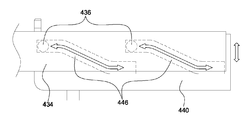
- FIG. 22 is a partial perspective view illustrating an operation structure of a cartridge storage unit of a sample pretreatment system according to an embodiment of the present invention
- FIG. 23 is an operation of raising or lowering the cartridge heater of the sample pretreatment system according to an embodiment of the present invention.
- 24 is a perspective view illustrating a state in which a cartridge is accommodated in a sample pretreatment system according to an exemplary embodiment of the present invention.
- the cartridge accommodating part 400 includes a cartridge holder 420 on which the cartridges 10 (see FIG. 24) are seated, and which loads or unloads the cartridge 10, and the cartridge. And a third motor 410 that provides a driving force for moving the holder 420 to the loading or unloading position.
- an illustration of a cover (not shown) covering the outside is omitted, and an entrance (not shown) through which the cartridge holder 420 may enter and exit the entire cover of the sample pretreatment system 1000. May be provided.
- the cartridge holder 420 may be drawn out or accommodated by a driving force of the third motor 410 provided below one side of the housing body 110. Specifically, the rotational force of the third motor 410 is transmitted to the accommodating pinion gear 412 by a combination of the belt, pulley and the drive gear.
- the accommodating pinion gear 412 meshes with the accommodating leg gear 422 formed in the cartridge holder 420 to transmit power. Therefore, the cartridge holder 420 may move to the withdrawal or storage position as the rotation shaft of the third motor 410 rotates in one direction or the opposite direction.
- the cartridge accommodating portion 400 further comprises a cartridge heater 430 for heating the loaded cartridge 10, the cartridge heater 430 to the loading or unloading of the cartridge 10 Can be configured to rise or fall accordingly.
- the cartridge heater 430 is fixedly installed at the heater connecting portion 432, and the heater connecting portion 432 is coupled to the lifting portion 434.
- the lifting unit 434 moves up or down in accordance with the storage or withdrawal of the cartridge holder 420.
- a rack guide 440 is additionally provided, and the rack guide 440 includes a guide line 424 having a guide protrusion 444 provided at one side of the cartridge holder 420. It is provided in the state of meshing with).
- the rack guide 440 moves along the path of the guide line 424. That is, when the cartridge holder 420 is moved out to the outside based on the plan view of FIG. 21, the rack guide 440 is horizontally moved upward in the drawing due to the guide protrusion 444 engaged with the guide line 424. .
- the rack guide 440 When the cartridge holder 420 is moved inwardly, the rack guide 440 horizontally moves downward in the drawing due to the guide protrusion 444 engaged with the guide line 424. At this time, the guide rack gear 442 formed on one side of the rack guide 440 is meshed with the accommodating pinion gear 412 can be more stable power transmission.
- the elevating guide line 446 is formed at one side of the vertical surface of the rack guide 440, and the elevating part protrusion 436 which is fitted to the elevating guide line 446 at the rear of the elevating part 434. ) Is formed.
- the reason for this configuration is to prevent the cartridge heater 430 and the cartridge holder 420 disposed below the cartridge 10 from interfering with or colliding with each other when the cartridge heater 430 moves for storage or withdrawal.
- the cartridge heater 430 may be lowered when the cartridge holder 420 is drawn out, and the cartridge heater 430 may be raised when the cartridge holder 420 is stored.
- the heater connection portion 432 is provided to surround at least a portion of the cartridge heater 430, when the cartridge heater 430 is raised, the heater connection portion 432 is the cartridge 10 ) Close to the bottom.
- the heater connection part 432 is preferably made of a material having excellent thermal conductivity, and transfers heat from the cartridge heater 430 which is a heat source to the cartridge 10 so that the cartridge 10 can be heated.
- the heater connection part 432 may be applied to a high aluminum material with high thermal conductivity.
- the thermal conductivity is good, but since the hardness is low, there is a problem of bending well.
- aluminum is applied to the heater connection part 432.
- the cartridge heater 430 Since the cartridge heater 430 is very hot, the cartridge 10 made of resin may melt when the cartridge heater 430 is in close contact with the cartridge 10. In order to prevent this, the cartridge heater 430 is indirectly heated through the heater connection part 432 made of a thermally conductive material. It is.
- the area covered by the heater connection part 432 is a reaction area R of the cartridge 10, and the heater connection part 432 has a larger area than the reaction area R of the cartridge 10. It is preferable to make.
- the cartridge heater 430 preferably has an area including an area of the heater connection part 432 covering the reaction area (R).
- the heater connection part 432 may uniformly and sufficiently transfer the heat dissipated from the cartridge heater 430 as the heat source to the reaction zone R. You must play a role.
- the area should be made large so as to have a relatively large heat capacity than the reaction region (R). If the heater connection portion 432 is smaller than the area of the reaction zone R, not only heat transfer is not performed, but also thermal gradient occurs in the reaction zone R, resulting in an imbalance in the flow of fluid in the channel of the cartridge 10. Can cause.
- the heater connection part 432 is configured to have a larger area than the reaction region R of the cartridge 10.
- the thermal conductivity of aluminum is good as long as the area of the cartridge heater 430 itself is smaller or shifted from the area covered by the heater connection part 432. Even if the heat connection occurs in the heater connection portion 432 itself may adversely affect the fluid flow.
- the cartridge heater 430 is configured to have an area including the area of the heater connection part 432 covering the reaction area (R).
- the heater connection portion 432 is preferably made of a flat shape.
- the cartridge heater 430 is preferably made of a flat shape corresponding to the contact surface with the heater connection portion 432.
- the reason why the cartridge heater 430 and the heater connection part 432 are made flat to correspond to the contact surface of the cartridge 10 is to minimize the air layer because heat loss occurs due to air if the contact areas are not in close contact with each other. It is for close contact.
- FIG. 24 is a perspective view illustrating a state in which a cartridge is accommodated in a sample pretreatment system according to an exemplary embodiment of the present invention
- FIG. 25 illustrates doping gold nanoparticles in a dotting member of a sample pretreatment module according to an exemplary embodiment of the present invention
- FIG. 26 is a diagram illustrating a process of dotting and drying a buffer in a chamber of a sample pretreatment module according to an embodiment of the present invention.
- FIG. 27 is a view illustrating a state in which each part of the sample pretreatment module is assembled according to an embodiment of the present invention
- FIG. 28 is a state in which a sample is injected into a chamber of the sample pretreatment module according to an embodiment of the present invention.
- FIG. 29 is a diagram illustrating a process of mixing a sample by applying magnetic force to a permanent magnet of a sample pretreatment module according to an embodiment of the present invention.
- 30 is a block diagram illustrating a process of pressing a cap rim portion of a sample pretreatment module according to an embodiment of the present invention and penetrating the through membrane
- FIG. 31 is a pressing unit of the sample pretreatment module cap according to an embodiment of the present invention. It is a block diagram which shows the process of discharging a sample.
- the cartridge 10 is placed in the cartridge accommodating part 400 and then stored.
- the cartridge heater 430 which has been lowered as described above, rises and comes into close contact with the lower portion of the cartridge 10.
- the cartridge 10 is heated to a predetermined temperature by the cartridge heater 430, so that the temperature of the cartridge 10 is maintained at about 32 ° C, for example, so that the antigen antibody reaction can be smoothly performed in the cartridge 10. Can be.
- an additional sample is doped into the second extension 138 of the dotting member 130 to be inserted into the sample pretreatment module 100.
- gold nanoparticles G are doped and dried in the second extension part 138.
- a release buffer is doped and dried on the through membrane 116 in the chamber 112 of the sample pretreatment module 100.
- vitamin D may be used as a buffer.
- each part of the sample pretreatment module 100 is assembled. That is, the permanent magnet 132 and the dotting member 130 are disposed in the chamber 112, and the discharge tip 140 is coupled to the body 110. At this time, the discharge tip 140 is a state in which only a part of the penetration portion 146 is inserted so as not to penetrate the through-membrane 116. Then, the moving part 124 is inserted into the hollow part 122 of the cap 120.
- the cap 120 is closed, and then the sample pretreatment module 100 is seated and loaded in the module holder 520 of the sample pretreatment system 1000.
- a magnetic force acts on the permanent magnet 132 to rotate. Mixing of the samples can be made.
- the module heater 524 is operated to heat the sample. Specifically, for example, the applied temperature is heated at 49 ° C. for about 10 minutes in vitamin D mode, and at about 5 minutes at 37 ° C. in Free T4 and testosterone. .
- the edge pressing portion 220 presses the cap edge portion 129 downward to penetrate the through membrane 116.
- the moving part pressing part 230 moves downward, as shown in FIG. 31, and presses the moving part 124 located in the hollow part 122 of the cap 120. .
- the moving part 124 When the moving part 124 is pressed downward while moving, the sample in the chamber 112 is discharged quantitatively through the discharge part 142. At this time, since the moving unit 124 is pressed by the moving unit pressing unit 230 at a constant moving distance and speed, the amount of discharged can be constantly maintained in a fixed amount.
- the discharged sample is dropped in the fluid analysis cartridge 10 located at the bottom and used for diagnosis and analysis.
- the number of drops is sensed using the aforementioned counting sensor 600.
- the normal number of drops required for sample loading may be set in advance, and when it is out of the normal number, it may be determined as an error mode.
- the error code can be set as follows.
- the causes of the error are as follows.
- the position is set by coordinate the position on the basis of the lower end of the edge pressing unit 220. In this case, it is determined that the normal number of drops is exceeded.
- the causes of the error are as follows.
- the sample is excessively ejected at the timing that the penetrating portion 146 penetrates the penetrating membrane 116 before pressing the moving portion 124.
- the number of drops is counted within a time shorter than the drop time, it is recognized as an error. For example, when measuring 5 drops, if all 5 drops are counted within 10 seconds, the drop can be recognized as an error so that the drop can be detected faster than normal. In this case, it is determined that the normal number of drops is exceeded.
- the causes of the error are as follows.
- the sample is excessively ejected at the timing that the penetrating portion 146 penetrates the penetrating membrane 116 before pressing the moving portion 124.
- the drop is detected when the moving part pressurizing unit 230 rises to the initial position after the normal operation, it is determined as an error. In this case, it is determined that the normal number of drops is exceeded.
- the causes of the error are as follows.
- an error is determined by setting a sufficient time that the normal drop is expected to be completely completed as a reference time. For example, when the normal operation time is about 1 minute 30 seconds, the set time is 3 minutes. In this case, it is considered that the number of drops is less than normal.
- the causes of the error are as follows.
- Table 1 and Table 2 are the results of the actual pretreatment and quantitative discharging experiment using the sample pretreatment module 100 of the present invention, the plasma and gold particles were mixed and maintained at 37 °C for 5 minutes.
- the module of (4) is heated to 37 ° C. for 5 minutes in a pretreatment system unit.
- sample pretreatment system according to the embodiments of the present invention described so far can minimize errors that may occur when the operator proceeds by hand, and ensure the accuracy and uniformity of the sample pretreatment and test results.
- all processes of sample mixing and discharging and loading into the diagnostic cartridge can be automatically and conveniently improved to provide convenience and provide a user-friendly experimental environment.
- the module and cartridge are automatically heated to maintain the desired temperature for the desired time to improve the mixing efficiency and reaction efficiency, and to prevent the sample from bursting under rapid pressure changes in the chamber.
- the pressure inside can be maintained and controlled uniformly, and the heat transfer power of the sample contained in the chamber can be increased to heat the desired temperature in a short time to increase the mixing and reaction efficiency of the sample.
- the magnetic force can be used to increase the mixing effect of the sample and to minimize mechanical driving, and a one-stop service for pretreatment, quantitative ejection and loading of the sample is possible.
Landscapes
- Chemical & Material Sciences (AREA)
- Health & Medical Sciences (AREA)
- General Health & Medical Sciences (AREA)
- Analytical Chemistry (AREA)
- Life Sciences & Earth Sciences (AREA)
- Biochemistry (AREA)
- Physics & Mathematics (AREA)
- General Physics & Mathematics (AREA)
- Immunology (AREA)
- Pathology (AREA)
- Chemical Kinetics & Catalysis (AREA)
- Clinical Laboratory Science (AREA)
- Hematology (AREA)
- Sampling And Sample Adjustment (AREA)
Abstract
Description
| drop | 용량(ul) | |
| Sample-1 | 3 | 35 |
| Sample-2 | 3 | 35 |
| Sample-3 | 3 | 33 |
| Sample-4 | 3 | 33 |
| Sample-5 | 3 | 35 |
| Sample-6 | 3 | 35 |
| Sample-7 | 3 | 35 |
| Sample-8 | 3 | 35 |
| Sample-9 | 3 | 33 |
| Sample-10 | 3 | 35 |
| Drop volume Ave. | 34.40 | |
| 표준편차 | 0.9661 | |
| CV% | 2.81 | |
| drop | 용량(ul) | |
| Sample-1 | 3 | 33 |
| Sample-2 | 3 | 33 |
| Sample-3 | 3 | 33 |
| Sample-4 | 3 | 32 |
| Sample-5 | 3 | 33 |
| Sample-6 | 3 | 34 |
| Sample-7 | 3 | 34 |
| Sample-8 | 3 | 33 |
| Sample-9 | 3 | 34 |
| Sample-10 | 3 | 35 |
| Drop volume Ave. | 33.40 | |
| 표준편차 | 0.8433 | |
| CV% | 2.52 | |
Claims (17)
- 샘플 전처리 모듈이 안착되는 모듈 홀더가 구비되는 홀더 출납부;상기 샘플 전처리 모듈의 챔버에 수용된 샘플이 배출되어 로딩(loading)되는 카트리지가 수납되는 카트리지 수납부;상기 샘플 전처리 모듈 내에 구비된 영구자석을 회전시키도록 자력을 생성하는 자력 생성부; 및상기 샘플 전처리 모듈의 관통막을 관통시키고, 캡의 이동부를 가압하여 상기 샘플을 배출시키는 관통 및 배출 실행부;를 포함하는 샘플 전처리 시스템.
- 제1항에 있어서,상기 모듈 홀더는,상기 모듈 홀더 외측을 둘러싸도록 구비되며, 상기 샘플 전처리 모듈을 가열하는 모듈 히터;를 포함하는 샘플 전처리 시스템.
- 제1항에 있어서,상기 관통 및 배출 실행부는,상기 샘플 전처리 모듈의 캡 테두리부를 가압하여 상기 샘플 전처리 모듈 내부의 관통막을 뚫는 테두리 가압부와,상기 이동부를 가압하여 상기 샘플을 배출시키는 이동부 가압부를 포함하는 샘플 전처리 시스템.
- 제3항에 있어서,상기 관통 및 배출 실행부는,상기 테두리 가압부가 연결되는 제1 이동바와, 상기 이동부 가압부와 연결되는 제2 이동바 및, 상기 제1 이동바와 제2 이동바를 구동시키는 제1 모터를 더 포함하며,상기 제1 이동바와 제2 이동바는 제1 모터의 구동에 따라 서로 멀어지는 방향 또는 서로 가까워지는 방향으로 동시에 이동하는 것을 특징으로 하는 샘플 전처리 시스템.
- 제4항에 있어서,상기 관통 및 배출 실행부는,상기 테두리 가압부 중앙부에 형성되는 통공을 더 포함하며,상기 이동부 가압부는 상기 통공을 통과하여 이동하면서 상기 이동부를 가압하는 것을 특징으로 하는 샘플 전처리 시스템.
- 제1항에 있어서,상기 자력 생성부는,상기 모듈 홀더 일측에 회전 가능하게 설치되는 볼텍싱(vortexing) 자석과,상기 볼텍싱 자석을 회전시키는 제2 모터를 포함하는 샘플 전처리 시스템.
- 제1항에 있어서,상기 카트리지 수납부는,상기 카트리지가 안착되며, 상기 카트리지를 로딩 또는 언로딩하는 카트리지 홀더와,상기 카트리지 홀더를 로딩 또는 언로딩 위치로 이동시키기 위한 구동력을 제공하는 제3 모터를 포함하는 샘플 전처리 시스템.
- 제7항에 있어서,상기 카드리지 수납부는 로딩된 상기 카트리지를 가열하는 카트리지 히터를 더 포함하며,상기 카트리지 히터는 상기 카트리지의 로딩 또는 언로딩에 따라 상승 또는 하강하는 것을 특징으로 하는 샘플 전처리 시스템.
- 제8항에 있어서,상기 카트리지 히터의 적어도 일부를 둘러싸고, 상기 카트리지에 밀착하는 히터 연결부를 더 포함하며,상기 히터 연결부는 상기 카트리지의 반응영역보다 더 큰 면적을 갖도록 구비되는 것을 특징으로 하는 샘플 전처리 시스템.
- 제9항에 있어서,상기 카트리지 히터는 상기 카트리지 반응영역을 커버하는 히터 연결부의 영역을 포함하는 면적을 갖도록 구비되는 것을 특징으로 하는 샘플 전처리 시스템.
- 제9항에 있어서,상기 히터 연결부는 상기 카트리지 반응영역에 밀착하도록 평평한 형상으로 이루어지는 것을 특징으로 하는 샘플 전처리 시스템.
- 제11항에 있어서,상기 카트리지 히터는 상기 카트리지와 상기 히터 연결부와의 접촉면에 상응하도록 평평한 형상으로 이루어지는 것을 특징으로 하는 샘플 전처리 시스템.
- 제1항에 있어서,상기 홀더 출납부는 상기 모듈 홀더를 이동하여 상기 모듈 홀더에 안착된 샘플 전처리 모듈을 로딩 또는 언로딩하는 구동력을 제공하는 제4 모터를 더 포함하는 샘플 전처리 시스템.
- 제1항에 있어서,상기 샘플이 배출되는 드랍(drop) 횟수를 감지하는 카운팅 센서를 더 포함하는 샘플 전처리 시스템.
- 카트리지를 카트리지 홀더에 안착시킨 후 카트리지 수납부로 로딩하는 단계;챔버 내에 샘플을 수용한 샘플 전처리 모듈을 모듈 홀더에 안착시킨 후 로딩하는 단계;상기 모듈 홀더 일측에 위치한 볼텍싱 자석을 회전시킴으로써 상기 챔버 내에 구비된 영구자석을 회전시키는 단계;상기 샘플 전처리 모듈의 캡 테두리부를 가압하여 상기 샘플 전처리 모듈 내부의 관통막을 뚫는 단계; 및,상기 샘플 전처리 모듈의 캡의 이동부를 가압하여 상기 샘플을 배출시킴으로써 상기 카트리지에 샘플을 로딩하는 단계;를 포함하는 샘플 전처리 시스템의 제어방법.
- 제15항에 있어서,상기 카트리지를 가열하여 일정 온도로 유지하는 단계를 더 포함하는 샘플 전처리 시스템의 제어방법.
- 제15항에 있어서,상기 모듈 홀더에 안착된 샘플 전처리 모듈을 가열하여 일정 온도로 일정 시간 동안 유지하는 단계를 더 포함하는 샘플 전처리 시스템의 제어방법.
Priority Applications (4)
| Application Number | Priority Date | Filing Date | Title |
|---|---|---|---|
| JP2018530455A JP6606616B2 (ja) | 2015-09-04 | 2016-08-30 | サンプル前処理システム及びその制御方法 |
| EP16842246.7A EP3346255B1 (en) | 2015-09-04 | 2016-08-30 | Sample pretreatment system |
| US15/757,551 US10801931B2 (en) | 2015-09-04 | 2016-08-30 | Sample pretreatment system and control method therefor |
| CN201680051212.XA CN107923822B (zh) | 2015-09-04 | 2016-08-30 | 样品前处理系统 |
Applications Claiming Priority (2)
| Application Number | Priority Date | Filing Date | Title |
|---|---|---|---|
| KR1020150125867A KR101810942B1 (ko) | 2015-09-04 | 2015-09-04 | 샘플 전처리 시스템 및 그 제어방법 |
| KR10-2015-0125867 | 2015-09-04 |
Publications (1)
| Publication Number | Publication Date |
|---|---|
| WO2017039280A1 true WO2017039280A1 (ko) | 2017-03-09 |
Family
ID=58189039
Family Applications (1)
| Application Number | Title | Priority Date | Filing Date |
|---|---|---|---|
| PCT/KR2016/009641 Ceased WO2017039280A1 (ko) | 2015-09-04 | 2016-08-30 | 샘플 전처리 시스템 및 그 제어방법 |
Country Status (6)
| Country | Link |
|---|---|
| US (1) | US10801931B2 (ko) |
| EP (1) | EP3346255B1 (ko) |
| JP (1) | JP6606616B2 (ko) |
| KR (1) | KR101810942B1 (ko) |
| CN (1) | CN107923822B (ko) |
| WO (1) | WO2017039280A1 (ko) |
Cited By (1)
| Publication number | Priority date | Publication date | Assignee | Title |
|---|---|---|---|---|
| CN112858651A (zh) * | 2021-01-05 | 2021-05-28 | 内蒙古大学 | 一种用于测量生物学参数的装置 |
Families Citing this family (9)
| Publication number | Priority date | Publication date | Assignee | Title |
|---|---|---|---|---|
| KR101978821B1 (ko) * | 2017-05-16 | 2019-05-15 | 에스케이텔레콤 주식회사 | 카트리지를 이용한 핵산 추출 장치 |
| KR101978822B1 (ko) * | 2017-05-16 | 2019-05-15 | 에스케이텔레콤 주식회사 | 카트리지를 이용한 핵산 분석 장치 |
| CN110998333B (zh) * | 2017-05-16 | 2023-08-25 | Sk电信有限公司 | 使用盒的核酸分析设备 |
| US10241014B2 (en) * | 2017-07-10 | 2019-03-26 | Cem Corporation | Instrument for analytical sample preparation |
| US10330573B2 (en) * | 2017-07-10 | 2019-06-25 | Cem Corporation | Rapid sample preparation for analytical analysis using dispersive energized extraction |
| KR102149407B1 (ko) * | 2018-07-23 | 2020-08-31 | 주식회사 네오나노텍 | 생체 시료의 혼합 효율 개선을 위한 구조체 |
| CN113613787B (zh) * | 2019-02-20 | 2023-06-13 | 加利福尼亚太平洋生物科学股份有限公司 | 用于检测化学和生物分析物的扫描装置和方法 |
| CN109967144B (zh) * | 2019-03-25 | 2021-02-19 | 宁波美康盛德生物科技有限公司 | 用于检测微流控芯片的干式化学分析仪及微流控芯片 |
| KR102806525B1 (ko) * | 2022-11-11 | 2025-05-16 | (주)마이크로디지탈 | 복잡 시료 전처리 장치 및 복잡 시료 전처리 방법 |
Citations (5)
| Publication number | Priority date | Publication date | Assignee | Title |
|---|---|---|---|---|
| JP2005218413A (ja) * | 2004-02-09 | 2005-08-18 | Mitsutech Kk | 細胞培養装置 |
| JP2007163190A (ja) * | 2005-12-09 | 2007-06-28 | Yamaha Motor Engineering Kk | ろ過方法、ろ過装置及び試料分析前処理装置 |
| KR20090107927A (ko) * | 2008-04-09 | 2009-10-14 | (주)바이오니아 | 자동정제장치, 멀티 웰 플레이트 키트 및 생물학적 시료로부터 핵산을 추출하는 방법 |
| KR20120131437A (ko) * | 2011-05-25 | 2012-12-05 | 한국외국어대학교 연구산학협력단 | 시료 전처리 장치 및 시료 전처리 방법 |
| KR20130083305A (ko) * | 2012-01-12 | 2013-07-22 | 강릉원주대학교산학협력단 | 자성 입자를 이용한 분석물질의 전처리 장치, 이를 이용한 분석물질의 검출장치 및 검출방법 |
Family Cites Families (21)
| Publication number | Priority date | Publication date | Assignee | Title |
|---|---|---|---|---|
| JP3365806B2 (ja) * | 1993-02-25 | 2003-01-14 | オリンパス光学工業株式会社 | 自動分注装置 |
| US5432098A (en) * | 1994-10-31 | 1995-07-11 | Dynatech Precision Sampling Corporation | Apparatus, and process, for automatically sampling solids and semi-solids materials for analysis |
| US20030185096A1 (en) * | 2002-11-26 | 2003-10-02 | Hollstein Thomas E. | Apparatus and methods for dispensing minute amounts of liquid |
| JP4632262B2 (ja) * | 2003-02-05 | 2011-02-16 | アイキューム,インク. | サンプルの処理 |
| KR20060059750A (ko) * | 2004-11-29 | 2006-06-02 | 안진희 | 스트로를 구비한 용기마개 |
| JP4650102B2 (ja) * | 2005-05-24 | 2011-03-16 | ニプロ株式会社 | 検体採取液容器 |
| JP2007000719A (ja) * | 2005-06-22 | 2007-01-11 | Fuji Xerox Co Ltd | マイクロリアクター用注入装置 |
| DE102006002258B4 (de) * | 2006-01-17 | 2008-08-21 | Siemens Ag | Modul zur Aufbereitung einer biologischen Probe, Biochip-Satz und Verwendung des Moduls |
| US20080017577A1 (en) * | 2006-07-21 | 2008-01-24 | Becton, Dickinson And Company | Membrane-based Double-layer Tube for Sample Collections |
| JP2008253980A (ja) * | 2007-03-13 | 2008-10-23 | Nichiriyoo:Kk | ピペット及びプランジャのプランジャシール機構 |
| JP2008286719A (ja) * | 2007-05-21 | 2008-11-27 | Panasonic Corp | 採取セル、採取装置、及び測定装置 |
| WO2009125971A2 (ko) | 2008-04-09 | 2009-10-15 | (주)바이오니아 | 자동정제장치, 멀티 웰 플레이트 키트 및 생물학적 시료로부터 핵산을 추출하는 방법 |
| CN102015482B (zh) * | 2008-04-24 | 2013-07-17 | 东洋制罐株式会社 | 复式容器以及注出方法 |
| EP2315824A4 (en) * | 2008-08-26 | 2012-08-22 | Wako Pure Chem Ind Ltd | DISPOSABLE DEVICE FOR THE AUTOMATIC PREPARATION OF BIOLOGICAL SAMPLES |
| FR2938063B1 (fr) * | 2008-11-05 | 2014-09-19 | Commissariat Energie Atomique | Dispositif de preparation et/ou de traitement d'un echantillon biologique |
| JP2010174817A (ja) * | 2009-01-30 | 2010-08-12 | Nokodai Tlo Kk | シリンジポンプ |
| WO2013076998A1 (ja) * | 2011-11-25 | 2013-05-30 | 凸版印刷株式会社 | 分注装置に用いられるピペットチップセット及びこれを用いた試薬カートリッジフィルムへの穴開け方法 |
| US9075042B2 (en) * | 2012-05-15 | 2015-07-07 | Wellstat Diagnostics, Llc | Diagnostic systems and cartridges |
| CN204033940U (zh) * | 2014-06-25 | 2014-12-24 | 北华大学 | 一种补给式输液装置 |
| CN204192670U (zh) * | 2014-09-16 | 2015-03-11 | 万鹏 | 一次性蛛网膜下腔旋转式脑脊液采集、显示、测压装置 |
| CN204582604U (zh) * | 2015-03-06 | 2015-08-26 | 瑞基海洋生物科技股份有限公司 | 萃取装置 |
-
2015
- 2015-09-04 KR KR1020150125867A patent/KR101810942B1/ko active Active
-
2016
- 2016-08-30 JP JP2018530455A patent/JP6606616B2/ja active Active
- 2016-08-30 EP EP16842246.7A patent/EP3346255B1/en active Active
- 2016-08-30 US US15/757,551 patent/US10801931B2/en active Active
- 2016-08-30 WO PCT/KR2016/009641 patent/WO2017039280A1/ko not_active Ceased
- 2016-08-30 CN CN201680051212.XA patent/CN107923822B/zh active Active
Patent Citations (5)
| Publication number | Priority date | Publication date | Assignee | Title |
|---|---|---|---|---|
| JP2005218413A (ja) * | 2004-02-09 | 2005-08-18 | Mitsutech Kk | 細胞培養装置 |
| JP2007163190A (ja) * | 2005-12-09 | 2007-06-28 | Yamaha Motor Engineering Kk | ろ過方法、ろ過装置及び試料分析前処理装置 |
| KR20090107927A (ko) * | 2008-04-09 | 2009-10-14 | (주)바이오니아 | 자동정제장치, 멀티 웰 플레이트 키트 및 생물학적 시료로부터 핵산을 추출하는 방법 |
| KR20120131437A (ko) * | 2011-05-25 | 2012-12-05 | 한국외국어대학교 연구산학협력단 | 시료 전처리 장치 및 시료 전처리 방법 |
| KR20130083305A (ko) * | 2012-01-12 | 2013-07-22 | 강릉원주대학교산학협력단 | 자성 입자를 이용한 분석물질의 전처리 장치, 이를 이용한 분석물질의 검출장치 및 검출방법 |
Non-Patent Citations (1)
| Title |
|---|
| See also references of EP3346255A4 * |
Cited By (1)
| Publication number | Priority date | Publication date | Assignee | Title |
|---|---|---|---|---|
| CN112858651A (zh) * | 2021-01-05 | 2021-05-28 | 内蒙古大学 | 一种用于测量生物学参数的装置 |
Also Published As
| Publication number | Publication date |
|---|---|
| CN107923822A (zh) | 2018-04-17 |
| US20180259432A1 (en) | 2018-09-13 |
| EP3346255A1 (en) | 2018-07-11 |
| EP3346255B1 (en) | 2022-10-05 |
| CN107923822B (zh) | 2021-01-05 |
| EP3346255A4 (en) | 2019-05-22 |
| JP2018529984A (ja) | 2018-10-11 |
| US10801931B2 (en) | 2020-10-13 |
| KR20170028796A (ko) | 2017-03-14 |
| JP6606616B2 (ja) | 2019-11-13 |
| KR101810942B1 (ko) | 2018-01-25 |
Similar Documents
| Publication | Publication Date | Title |
|---|---|---|
| WO2022039512A1 (ko) | 다채널 혈액 점도 측정 장치 | |
| US20130008628A1 (en) | Thermal chamber for ic chip testing | |
| WO2018212508A2 (ko) | 핵산 추출용 카트리지 및 핵산 추출 방법 | |
| WO2013129872A1 (ko) | 소자검사장치 | |
| WO2019240475A1 (ko) | 가교 폴리올레핀 분리막 및 이의 제조방법 | |
| WO2012124952A2 (ko) | 사막기후 환경에 따른 내구성 시험장치 | |
| EP3346255B1 (en) | Sample pretreatment system | |
| WO2017191959A1 (ko) | 충전장치 | |
| WO2016182382A1 (ko) | 일체화된 반응 및 검출 수단을 구비한 시험 장치에 사용되는 스테이션 | |
| WO2022075676A1 (ko) | 핵산증폭검사장치 및 이를 구비하는 시료자동분석시스템 | |
| WO2018016858A1 (ko) | 원심 분리용 용기, 및 원심 분리용 용기 내의 물질 이동 방법 | |
| WO2019146923A1 (ko) | 청소기 | |
| AU2020270867A1 (en) | Washing machine | |
| WO2023018194A1 (ko) | Pcr 장치 | |
| WO2022220369A1 (ko) | 피부 부착형 유체 포집 패치 및 그의 제조방법 | |
| WO2017159960A1 (ko) | 엑스선관모듈의 절연유 교체장치와 절연유 교체방법 | |
| WO2016144107A1 (ko) | 기판 오염물 분석 장치 및 기판 오염물 분석 방법 | |
| WO2024029737A1 (ko) | 자동 혈액 점도 측정 장치 | |
| US20180202717A1 (en) | Sample heating apparatus | |
| WO2019147075A1 (ko) | 주입 노즐 어셈블리와, 이를 이용한 이차전지 제조 장치 및 방법 | |
| WO2017039279A1 (ko) | 샘플 전처리 모듈 및 이를 이용한 샘플 전처리 방법 | |
| WO2020197196A1 (ko) | 면역 검사 장치 및 면역 검사 방법 | |
| KR20090012710A (ko) | 기판 처리 장치 | |
| WO2011096782A2 (ko) | 액체 유동 장치와 액체 정량공급장치, 그리고 이를 이용한 목표물질 추출장치 및 목표물질 추출방법 | |
| WO2023121114A1 (ko) | 마이크로 웰 성형 장치 및 마이크로 웰을 가지는 디스크 제조 방법 |
Legal Events
| Date | Code | Title | Description |
|---|---|---|---|
| 121 | Ep: the epo has been informed by wipo that ep was designated in this application |
Ref document number: 16842246 Country of ref document: EP Kind code of ref document: A1 |
|
| ENP | Entry into the national phase |
Ref document number: 2018530455 Country of ref document: JP Kind code of ref document: A |
|
| WWE | Wipo information: entry into national phase |
Ref document number: 15757551 Country of ref document: US |
|
| NENP | Non-entry into the national phase |
Ref country code: DE |
|
| WWE | Wipo information: entry into national phase |
Ref document number: 2016842246 Country of ref document: EP |