WO2017043218A1 - 燃焼バーナ及びこれを備えたボイラ - Google Patents
燃焼バーナ及びこれを備えたボイラ Download PDFInfo
- Publication number
- WO2017043218A1 WO2017043218A1 PCT/JP2016/072564 JP2016072564W WO2017043218A1 WO 2017043218 A1 WO2017043218 A1 WO 2017043218A1 JP 2016072564 W JP2016072564 W JP 2016072564W WO 2017043218 A1 WO2017043218 A1 WO 2017043218A1
- Authority
- WO
- WIPO (PCT)
- Prior art keywords
- splitter
- fuel
- fuel gas
- splitters
- slit
- Prior art date
- Legal status (The legal status is an assumption and is not a legal conclusion. Google has not performed a legal analysis and makes no representation as to the accuracy of the status listed.)
- Ceased
Links
Images



Classifications
-
- F—MECHANICAL ENGINEERING; LIGHTING; HEATING; WEAPONS; BLASTING
- F23—COMBUSTION APPARATUS; COMBUSTION PROCESSES
- F23D—BURNERS
- F23D1/00—Burners for combustion of pulverulent fuel
-
- F—MECHANICAL ENGINEERING; LIGHTING; HEATING; WEAPONS; BLASTING
- F23—COMBUSTION APPARATUS; COMBUSTION PROCESSES
- F23D—BURNERS
- F23D23/00—Assemblies of two or more burners
-
- F—MECHANICAL ENGINEERING; LIGHTING; HEATING; WEAPONS; BLASTING
- F24—HEATING; RANGES; VENTILATING
- F24H—FLUID HEATERS, e.g. WATER OR AIR HEATERS, HAVING HEAT-GENERATING MEANS, e.g. HEAT PUMPS, IN GENERAL
- F24H9/00—Details
- F24H9/18—Arrangement or mounting of grates or heating means
- F24H9/1809—Arrangement or mounting of grates or heating means for water heaters
- F24H9/1832—Arrangement or mounting of combustion heating means, e.g. grates or burners
- F24H9/1845—Arrangement or mounting of combustion heating means, e.g. grates or burners using solid fuel
-
- F—MECHANICAL ENGINEERING; LIGHTING; HEATING; WEAPONS; BLASTING
- F23—COMBUSTION APPARATUS; COMBUSTION PROCESSES
- F23D—BURNERS
- F23D2201/00—Burners adapted for particulate solid or pulverulent fuels
- F23D2201/10—Nozzle tips
-
- F—MECHANICAL ENGINEERING; LIGHTING; HEATING; WEAPONS; BLASTING
- F23—COMBUSTION APPARATUS; COMBUSTION PROCESSES
- F23D—BURNERS
- F23D2201/00—Burners adapted for particulate solid or pulverulent fuels
- F23D2201/20—Fuel flow guiding devices
Definitions
- the present invention relates to a combustion burner and a boiler provided with the combustion burner.
- Patent Documents 1 and 2 below disclose a combustion burner in which a splitter shape is formed in a comb shape when the splitter is viewed from the downstream side.
- a wet edge length is securable by making a splitter into a comb-tooth shape.
- the splitter described in Patent Document 1 is configured to guide the pulverized coal to the outer peripheral side of the nozzle, and performs external ignition. With this, low NOx combustion cannot be realized.
- air is injected from a splitter, and combustion within the fuel nozzle is promoted to inhibit reduction combustion, so that low NOx combustion cannot be realized.
- the present invention has been made in view of such circumstances, and includes a combustion burner capable of realizing low NOx combustion by internal flame holding by increasing the wet edge length of the splitter and improving flame holding performance.
- the purpose is to provide a boiler.
- the combustion burner of the present invention and the boiler equipped with the same employ the following means. That is, the combustion burner according to one aspect of the present invention includes a fuel nozzle that blows a fuel gas in which fuel and air are mixed into a furnace, and a longitudinal axis at one end of the fuel nozzle at the tip side of the fuel nozzle.
- a plurality of splitters that extend from the side toward the other wall portion facing each other and divide the fuel gas flow by a widened portion that expands in the fuel gas flow direction, and the splitter includes A slitted slit formed with a slit for partially reducing the width of the downstream end of the fuel gas flow, and disposed adjacent to the slitted splitter, and the width of the downstream end of the fuel gas flow of the widened portion is the length of the longitudinal axis. It has a slitless splitter made constant in the direction.
- the slitless splitter has a flame holding function by forming a recirculation region downstream of the widened portion, but as a guide member that guides fuel to the adjacent slitted splitter using the inclined surface of the widened portion. It also has a function. Thereby, the internal flame holding in the splitter with a slit is further strengthened.
- a combustion burner includes a fuel nozzle for injecting a fuel gas mixed with fuel and air into a furnace, and a longitudinal axis at one end of the fuel nozzle.
- a plurality of splitters that extend from the section side to the opposing other wall section side and divide the fuel gas flow by a widened section that increases in width in the fuel gas flow direction, and the splitter includes the widened section
- Each of the adjacent splitters with slits is not formed with the slit of the widened portion.
- the wide surfaces are facing each other.
- the slitted splitters are arranged adjacent to each other and the wide surfaces where no slits are formed are opposed to each other, the fuel guided to the wide surface of one splitter is guided downstream of the other splitter. In this way, since the fuel is guided by the adjacent wide surfaces facing each other, flame holding is strengthened in both splitters. Further, since air is not injected from the splitter, the flow of the guided fuel is not hindered.
- the surface of the splitter with slits that forms the slit may be an inclined surface that deflects the fuel gas flow in the longitudinal axis direction.
- the fuel gas flow is deflected in the direction of the longitudinal axis of the splitter by the inclined surface that forms the slit, so that the fuel gas flow can be disturbed also in the longitudinal axis direction, and flame holding performance can be further improved.
- the slit can be formed three-dimensionally by each surface constituting the slit, and the flame holding performance can be improved.
- the splitter may be arranged at a different position in the fuel gas flow direction.
- the widened portion of the splitter is larger than when the splitter is disposed at the same position in the fuel gas flow direction.
- the occupied area can be reduced.
- the fuel can be guided to the recirculation region of the downstream splitter by the splitter located on the upstream side of the fuel gas flow, and the ignition or flame holding of the downstream splitter can be enhanced.
- the upstream side is a slitless splitter and the downstream side is a slitted splitter.
- a rectifying plate for separating the wall surface side of the fuel nozzle and the splitter may be provided at an end of the splitter in the longitudinal direction.
- this end portion may be ignited and the external ignition may occur at the outer peripheral portion of the fuel nozzle. Since a combustion air supply nozzle and the like exist outside the fuel nozzle and there is a large amount of oxygen, a large amount of NOx is generated when external ignition occurs. Therefore, by providing a rectifying plate that separates the wall surface side of the fuel nozzle and the splitter, external ignition that is ignited at the end of the splitter can be suppressed, and internal ignition or flame holding can be further strengthened. .
- a corner removing portion from which a corner portion is removed may be formed at a corner portion at the downstream end of the widened portion of the splitter.
- a corner is formed at the corner at the downstream end of the widened portion of the splitter, ignition is generated starting from the corner by receiving radiation from the inner peripheral surface of the fuel nozzle, and external ignition at the outer periphery of the fuel nozzle is performed. May occur. Since a combustion air supply nozzle and the like exist outside the fuel nozzle and there is a large amount of oxygen, a large amount of NOx is generated when external ignition occurs. Therefore, ignition or flame holding is suppressed by forming a corner removal portion from which the corner portion is removed. As a corner
- a boiler according to an aspect of the present invention includes a furnace, the combustion burner according to any one of the above provided in the furnace, a flue provided on the downstream side of the furnace, and the flue. Heat exchanger.
- Providing a slit increases the length of the wetting edge on the front of the splitter and guides the fuel to the recirculation region formed by the adjacent splitter. Low NOx combustion by flame holding can be realized.
- the combustion burner of this embodiment mainly burns pulverized coal fuel (fuel) obtained by pulverizing coal with a mill, and is provided in a boiler (not shown).
- a plurality of combustion burners are provided for a boiler having heat exchange such as a superheater and an evaporator in the flue, and forms a flame in the furnace.
- a front view of the combustion burner 1 is shown in FIG.
- the combustion burner 1 includes a fuel nozzle 3 located on the inner side and a combustion air supply nozzle 4 surrounding the fuel nozzle 3.
- the combustion air supply nozzle 4 is a flow path through which only secondary air flows, and supplies air so as to go straight into the furnace. That is, the air flowing out from the combustion air supply nozzle 4 flows so as not to cross the fuel gas flowing out from the fuel nozzle 3 in parallel.
- a combustion tertiary air nozzle for supplying combustion air is provided outside the combustion air supply nozzle 4.
- the fuel nozzle 3 has a rectangular cross section when viewed from the front, and a fuel gas in which pulverized coal and air are mixed flows inside.
- the downstream side of the fuel gas flow is simply referred to as the downstream side
- the upstream side of the fuel gas flow is simply referred to as the upstream side.
- a plurality of splitters 5, 6, and 7 are provided, and in this embodiment, five splitters are provided.
- Each of the splitters 5, 6, and 7 is provided with a longitudinal axis extending from the lower wall portion (one wall portion) 3 a side of the fuel nozzle 3 to the opposing upper wall portion (other wall portion) 3 b side.
- each splitter 5, 6, 7 is a vertical splitter provided in the vertical direction.
- the upper and lower ends of each of the splitters 5, 6, 7 are fixed to the wall portion of the fuel nozzle 3 by support members 8.
- the fuel nozzle 3 is provided with a nozzle angle adjusting mechanism that can rotate in the vertical direction together with the splitters 5, 6, and 7.
- the flow of the fuel gas is not largely deflected even if the nozzle angle is adjusted in the vertical direction.
- the splitters 5, 6, and 7 are members having a function of dividing the fuel gas flow, and do not have a function of injecting air from the inside.
- the splitter includes the splitters 5 and 6 with slits provided at both ends in the center and the horizontal direction, and the slitless splitter 7 provided on both sides of the splitter 5 with the center slit. In this way, the slitless splitter 7 is disposed at a position adjacent to the slitted splitters 5 and 6.
- the splitters 5, 6, and 7 include a widened portion 10 whose width increases in the fuel gas flow direction.
- a plate-like portion 11 extending in the vertical direction is provided on the upstream side of the widened portion 10 along the fuel gas flow direction.
- the widened portion 10 has a substantially triangular shape when viewed in cross section as shown in FIG.
- the widened portion 10 of the slitted splitter 5 and the slitless splitter 7 at the center spreads on both sides when viewed in cross section as shown in FIG.
- the widened portion 10 of the slitted splitter 6 located at both ends in the horizontal direction extends toward the center side of the fuel nozzle 3, but does not extend toward the wall portion side of the fuel nozzle 3.
- the air flowing out from the combustion air supply nozzle 4 is the fuel gas flowing between the wall surface of the fuel nozzle 3 and the slitted splitter 6. It does not deflect to the flow side. Thereby, the external ignition which arises on the outer peripheral side of the fuel nozzle 3 can be suppressed.
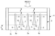
- the downstream ends 5a and 6a of the slitted splitters 5 and 6 are aligned with the position of the downstream end 3c of the fuel nozzle 3, as shown in FIG.
- the downstream end 7 a of the slitless splitter 7 is provided at a position separated by a predetermined distance S on the upstream side of the downstream ends 5 a and 6 a of the slitted splitters 5 and 6.
- the predetermined distance S is 0.001D or more and 1.0D or less, preferably 0.03D or more and 0.5D or less, more preferably 0.05D or more and 0, where D is the equivalent circular diameter at the opening of the fuel nozzle 3. .3D or less.
- Said lower limit and upper limit are determined from the following viewpoint.
- the distance between the splitters 5 and 6 with slits and the splitter 7 without slits becomes too short, and the advantage of securing the channel cross-sectional area by shifting these splitters cannot be obtained.
- the value exceeds the upper limit value the recirculation region formed by the slitless splitter 7 disappears before the splitters 5 and 6 with slits, and the recirculation region of the splitter 7 with slits from the splitters 5 and 6 with slits.
- the advantage of guiding the fuel gas cannot be obtained.
- the predetermined distance S may be adjusted by moving the slitless splitter 7 positioned on the upstream side in the fuel gas flow direction.
- the width of the downstream end 7a is constant in the direction of the longitudinal axis (vertical axis) of the slitless splitter 7.
- a plurality of slits SL for partially reducing the width of the downstream end 5a are formed in the central slitted splitter 5.
- the center slitted splitter 5 is provided with slits SL on both sides at the same height. By these slits, the wide part W1 and the narrow part W2 are formed in the splitter 5 with slits.
- FIG. 3 shows a specific shape of the slit SL.
- the slit SL is formed by notching the downstream end 5a of the slitted splitter 5 in a U-shape.
- the upper surface SL1 and the lower surface SL2 that form the slit SL are surfaces that deflect the fuel gas flow in the longitudinal axis direction of the splitter 5 (vertical direction in the present embodiment). That is, the fuel gas flow is deflected downward by the upper surface SL1, and the fuel gas flow is deflected upward by the lower surface SL2.
- the slits 6 with slits at both ends are also formed with the same slit SL as the splitter 5 with slits at the both ends.
- the slits SL are provided only on the central side of the fuel nozzle 3. It has been. This is because if the slit SL is provided also on the wall portion side of the fuel nozzle 3, it becomes an ignition surface and there is a risk of external ignition.
- the slit SL is preferably provided at the center in the longitudinal direction of the splitters 5 and 6 so that ignition or flame holding is performed on the center side of the fuel nozzle 3 as much as possible, and the slit SL is not provided at the upper and lower ends.
- L 1 in which the slit SL is provided when the length of the splitters 5 and 6 is L 0 , L 1 / L 0 is 0.8 or less, preferably 0.5 or less.
- rectifying plates 15 for separating the splitters 5, 6, 7 and the wall of the fuel nozzle 3 are provided at the upper and lower ends of the longitudinal axes of the splitters 5, 6, 7. Yes. Therefore, the upper rectifying plate 15 separates the fuel gas flowing on the splitters 5, 6 and 7 side from the fuel gas flowing on the upper wall 3 b side of the fuel nozzle 3. Further, the lower rectifying plate 15 separates the fuel gas flowing on the splitters 5, 6 and 7 side from the fuel gas flowing on the lower wall 3 a side of the fuel nozzle 3.
- the combustion burner 1 of the said structure there exist the following effects.
- Increasing the wet edge length by the slitted splitters 5 and 6 provided with the slit SL improves the flame holding property.
- the slitless splitter 7 has a flame holding function by forming a recirculation region downstream of the widened portion 10, but uses the inclined surface of the widened portion 10 to supply fuel to the adjacent slitted splitters 5, 6. It also has a function as a guiding member for guiding.
- the internal flame holding in the splitters 5 and 6 with slits is further strengthened.
- NOx generated in the burner flame region can be reduced by promoting reduction combustion.
- the fuel gas flow is deflected in the direction of the longitudinal axis of the splitters 5 and 6 by the upper surface SL1 and the lower surface SL2 which are inclined surfaces forming the slit SL, the fuel gas flow can be disturbed also in the longitudinal axis direction, and further the flame holding Performance can be improved.
- the slit SL can be three-dimensionally formed by each surface constituting the slit SL, and the flame holding performance can be improved.
- the area occupied by the widened portion 10 of the splitter is larger than when the splitters 5, 6, and 7 are arranged at the same position in the fuel gas flow direction. Can be reduced.
- the flow rate of the fuel gas toward the downstream side in the flow direction of the fuel gas can be brought close to the combustion speed of the fuel gas toward the upstream side. It can be ignited quickly before flowing into the flame, and the flame holding ability of the flame can be improved.
- Fuel is guided to the recirculation region of the downstream slitted splitters 5 and 6 by the slitless splitter 7 located on the upstream side of the fuel gas flow, and the ignition or flame holding of the downstream slitted splitters 5 and 6 is strengthened. Can do.
- the slitless splitter 7 when mainly having the function of guiding pulverized coal, it is preferable to use the slitless splitter 7.
- the rectifying plate 15 that separates the wall surface side of the fuel nozzle 3 and the splitters 5, 6, and 7, it is possible to suppress external ignition that ignites at the upper and lower ends of the splitters 5, 6, and 7. Ignition or flame holding in can be strengthened.
- the slitless splitter 7 is arranged on the upstream side, and the slitted splitters 5 and 6 are arranged on the downstream side. Conversely, the slitless splitter 7 is arranged on the downstream side, The splitters 5 and 6 with slits may be arranged on the upstream side. This configuration is used in the case of a fuel that is desired to be ignited early, and is ignited early by the upstream slitted splitters 5 and 6, and the slitless splitter is formed in the recirculation region formed by these splitters 5 and 6 with slits. To guide the fuel gas.
- all the splitters may be the slitted splitters 5 and 6.
- the slitted splitters 5 and 6 are adjacent to each other, and the wide portion W1 where the slit SL is not formed is opposed to each other, so that the fuel guided to the wide surface of one splitter is the other splitter. To the downstream side. In this way, since the fuel is guided between the adjacent wide portions W1 that are adjacent to each other, the flame holding is strengthened in both splitters.
- tapered portion is formed by removing the corner portion of the splitter 6, and the rest is the same. Therefore, the same reference numerals are assigned to common configurations, and descriptions thereof are omitted.
- tapered portions (corner removing portions) 20 are formed at the upper and lower corners on the center side of the fuel nozzle 3 of the splitter 6 with slits at both ends.
- the shape of the tapered portion 20 is not limited as long as the corner portion is removed, but as shown in FIG. 6, the apex angles ⁇ 1, ⁇ 2, ⁇ 3 of the three surfaces forming the corner portion are removed.
- any shape is acceptable. Therefore, it may be a flat surface such as a tapered surface, or may be composed of a curved surface.
- two rectifying plates 15a and 15b are provided. Each of the rectifying plates 15a and 15b is provided at a height position that is symmetric from the center position in the height direction of the fuel nozzle 3, and is a plate-like body that extends in the horizontal direction.
- the fuel nozzle 3 is ignited by receiving radiation from the inner peripheral surface side of the fuel nozzle 3 and starting from the corner portion. It is possible to suppress external ignition that occurs at the outer periphery of the.
- the tapered portion (corner removing portion) 20 may be provided in another splitter, that is, the splitter 5 with slit or the splitter 7 without slit.
- the number of splitters is five.
- the present invention is not limited to this, and may be two to four or six or more.
- the number of splitters is designed to be optimal depending on the size of the fuel nozzle.
- the vertical splitter in which the splitters 5, 6, and 7 extend in the vertical direction has been described as an example.
- the splitters 5, 6, and 7 can also be applied to the horizontal splitter in which the splitter extends in the horizontal direction.
- the present invention can be applied.
- pulverized coal was mainly demonstrated as fuel in embodiment mentioned above, it is not limited to this, This invention is applicable also to petroleum coke, a petroleum residue, and biomass fuel (solid form, slurry form). it can.
Landscapes
- Engineering & Computer Science (AREA)
- Chemical & Material Sciences (AREA)
- Combustion & Propulsion (AREA)
- Mechanical Engineering (AREA)
- General Engineering & Computer Science (AREA)
- Physics & Mathematics (AREA)
- Thermal Sciences (AREA)
- Combustion Of Fluid Fuel (AREA)
- Gas Burners (AREA)
Abstract
燃料ノズル(3)内の先端側に、長手軸線が燃料ノズル(3)の下壁部(3a)側から上壁部(3b)側へと延在して設けられ、燃料ガス流れ方向に幅が拡大する拡幅部によって燃料ガス流れを分割する複数のスプリッタ(5),(6),(7)とを備えている。スプリッタは、拡幅部の燃料ガス流れ下流端の幅を部分的に減少させるスリット(SL)が形成されたスリット付きスプリッタ(5),(6)と、スリット付きスプリッタ(5),(6)の隣に配置され、拡幅部の燃料ガス流れの下流端の幅が長手軸線の方向に一定とされたスリット無しスプリッタ(7)と有している。
Description
本発明は、燃焼バーナ及びこれを備えたボイラに関するものである。
微粉炭燃料を燃焼させる燃焼バーナとして、スプリッタと呼ばれる保炎器をバーナの燃料ノズル内の出口に複数本設置したものが知られている。そして、スプリッタの下流に再循環領域を形成し、微粉炭の燃焼を維持している。このように、燃料ノズルの中心軸状付近で着火及び保炎を行うこと(以下「内部着火」ないし「内部保炎」という。)で空気不足下での還元燃焼を行い低NOx燃焼を実現させている。
保炎性の向上には、保炎器の濡れ縁長さが長い方が良いが、スプリッタ本数を増やすとバーナ出口の閉塞率が高くなることでバーナ圧損が大きくなる。また、濡れ縁長さを確保するためにスプリッタ幅を小さくしてスプリッタ本数を増やしたとしても、燃料ノズルの壁部にスプリッタが近づくことになり、燃料ノズルの外周において着火が生じるおそれがある。燃料ノズルの外側には燃焼用空気供給ノズル等が存在しており酸素が多く存在するため、外部着火が生じるとNOxが多く発生してしまうおそれがある。
下記特許文献1及び2には、スプリッタを下流側から正面視した場合に、スプリッタ形状を櫛歯状に形成した燃焼バーナが開示されている。
各上記特許文献のように、スプリッタを櫛歯状にすることにより、濡れ縁長さを確保することができる。
しかし、特許文献1に記載のスプリッタは、微粉炭をノズルの外周側に導くように構成されており、外部着火を行うようになっている。これでは低NOx燃焼を実現することができない。
特許文献2は、スプリッタから空気を噴射するようになっており、燃料ノズル内部での燃焼が促進されて還元燃焼を阻害してしまい低NOx燃焼が実現できない。
しかし、特許文献1に記載のスプリッタは、微粉炭をノズルの外周側に導くように構成されており、外部着火を行うようになっている。これでは低NOx燃焼を実現することができない。
特許文献2は、スプリッタから空気を噴射するようになっており、燃料ノズル内部での燃焼が促進されて還元燃焼を阻害してしまい低NOx燃焼が実現できない。
本発明は、このような事情に鑑みてなされたものであって、スプリッタの濡れ縁長さを長くするとともに保炎性を向上させて内部保炎による低NOx燃焼を実現できる燃焼バーナ及びこれを備えたボイラを提供することを目的とする。
上記課題を解決するために、本発明の燃焼バーナ及びこれを備えたボイラは以下の手段を採用する。
すなわち、本発明の一態様にかかる燃焼バーナは、燃料と空気とを混合した燃料ガスを火炉内に吹き込む燃料ノズルと、該燃料ノズル内の先端側に、長手軸線が該燃料ノズルの一壁部側から対向する他壁部側へと延在して設けられ、燃料ガス流れ方向に幅が拡大する拡幅部によって燃料ガス流れを分割する複数のスプリッタとを備え、前記スプリッタは、前記拡幅部の燃料ガス流れ下流端の幅を部分的に減少させるスリットが形成されたスリット付きスプリッタと、該スリット付きスプリッタの隣に配置され、前記拡幅部の燃料ガス流れの下流端の幅が前記長手軸線の方向に一定とされたスリット無しスプリッタと有している。
すなわち、本発明の一態様にかかる燃焼バーナは、燃料と空気とを混合した燃料ガスを火炉内に吹き込む燃料ノズルと、該燃料ノズル内の先端側に、長手軸線が該燃料ノズルの一壁部側から対向する他壁部側へと延在して設けられ、燃料ガス流れ方向に幅が拡大する拡幅部によって燃料ガス流れを分割する複数のスプリッタとを備え、前記スプリッタは、前記拡幅部の燃料ガス流れ下流端の幅を部分的に減少させるスリットが形成されたスリット付きスプリッタと、該スリット付きスプリッタの隣に配置され、前記拡幅部の燃料ガス流れの下流端の幅が前記長手軸線の方向に一定とされたスリット無しスプリッタと有している。
スリット付きスプリッタは、スリットが形成されているため濡れ縁長さが長くなり、保炎性が向上する。これにより、燃料ノズルの内部で保炎する内部保炎が強化される。
スリット無しスプリッタは、拡幅部の下流に再循環領域を形成することによって保炎機能を有するが、拡幅部の傾斜面を利用して隣のスリット付きスプリッタに対して燃料を案内する案内部材としての機能も有する。これにより、スリット付きスプリッタでの内部保炎が更に強化される。
スリット無しスプリッタは、拡幅部の下流に再循環領域を形成することによって保炎機能を有するが、拡幅部の傾斜面を利用して隣のスリット付きスプリッタに対して燃料を案内する案内部材としての機能も有する。これにより、スリット付きスプリッタでの内部保炎が更に強化される。
また、本発明の他の態様にかかる燃焼バーナは、燃料と空気とを混合した燃料ガスを火炉内に吹き込む燃料ノズルと、該燃料ノズル内の先端側に、長手軸線が該燃料ノズルの一壁部側から対向する他壁部側へと延在して設けられ、燃料ガス流れ方向に幅が拡大する拡幅部によって燃料ガス流れを分割する複数のスプリッタとを備え、前記スプリッタは、前記拡幅部の燃料ガス流れ下流端の幅を部分的に減少させるスリットが形成された複数のスリット付きスプリッタを有し、隣り合う各前記スリット付きスプリッタは、それぞれの前記拡幅部の前記スリットが形成されていない幅広面が対向している。
スリット付きスプリッタが隣り合って配置されており、スリットが形成されていない幅広面が対向しているので、一方のスプリッタの幅広面に案内された燃料が他方のスプリッタの下流側へと導かれる。このように、隣り合って対向する幅広面どうしで燃料を案内し合うので、両方のスプリッタにおいても保炎が強化されることになる。
また、スプリッタからは空気を噴射しないので、案内された燃料の流れを妨げることがない。
また、スプリッタからは空気を噴射しないので、案内された燃料の流れを妨げることがない。
さらに、前記スリット付きスプリッタの前記スリットを形成する面が、燃料ガス流れを前記長手軸線方向に偏向させる傾斜面とされていても良い。
スリットを形成する傾斜面によりスプリッタの長手軸線の方向に燃料ガス流れを偏向させるので、燃料ガス流れを長手軸線方向にも乱すことができ、さらに保炎性能を向上させることができる。特に、スリットを構成する各面によってスリットを3次元的に形成することができ、保炎性能を向上させることができる。
さらに、前記スプリッタは、燃料ガス流れ方向において異なる位置に配置されていても良い。
スプリッタを燃料ガス流れ方向において異なる位置、つまり燃料ガス流れ方向の上流側と下流側にずらして配置することにより、スプリッタを燃料ガス流れ方向の同じ位置に配置する場合に比べてスプリッタの拡幅部が占める面積を減少させることができる。これにより、燃料ガスの増速を抑えることで、燃料ガスの流れ方向の下流側に向かう燃料ガスの流速を、上流側に向かう燃料ガスの燃焼速度に近づけることができ、燃料ガスがさらに下流側へ流れる前に、早く着火させることができ、火炎の保炎性を向上させることができる。
また、燃料ガス流れ上流側に位置するスプリッタで早期に着火を図り、下流側に位置するスプリッタで着火ないし保炎を強化することができる。
また、燃料ガス流れ上流側に位置するスプリッタで燃料を下流側のスプリッタの再循環領域に導き、下流側のスプリッタの着火ないし保炎を強化することができる。この場合、上流側がスリット無しスプリッタで、下流側がスリット付きスプリッタであることが好ましい。
また、燃料ガス流れ上流側に位置するスプリッタで早期に着火を図り、下流側に位置するスプリッタで着火ないし保炎を強化することができる。
また、燃料ガス流れ上流側に位置するスプリッタで燃料を下流側のスプリッタの再循環領域に導き、下流側のスプリッタの着火ないし保炎を強化することができる。この場合、上流側がスリット無しスプリッタで、下流側がスリット付きスプリッタであることが好ましい。
さらに、前記スプリッタの前記長手方向における端部には、前記燃料ノズルの壁面側と前記スプリッタとを分離する整流板が設けられていても良い。
スプリッタの長手方向における端部では、この端部が基点として着火が生じ、燃料ノズルの外周部における外部着火が発生するおそれがある。燃料ノズルの外側には燃焼用空気供給ノズル等が存在しており酸素が多く存在するため、外部着火が生じるとNOxが多く発生してしまう。
そこで、燃料ノズルの壁面側とスプリッタとを分離する整流板を設けることで、スプリッタの端部で着火する外部着火を抑制することができ、より内部での着火ないし保炎を強化することができる。
そこで、燃料ノズルの壁面側とスプリッタとを分離する整流板を設けることで、スプリッタの端部で着火する外部着火を抑制することができ、より内部での着火ないし保炎を強化することができる。
さらに、前記スプリッタの拡幅部の下流端における隅部には、角部が除去された角除去部が形成されていても良い。
スプリッタの拡幅部の下流端における隅部に角部が形成されていると、燃料ノズル内周面側からの輻射を受けて角部を起点として着火が生じ、燃料ノズルの外周部における外部着火が発生するおそれがある。燃料ノズルの外側には燃焼用空気供給ノズル等が存在しており酸素が多く存在するため、外部着火が生じるとNOxが多く発生してしまう。
そこで、角部を除去した角除去部を形成することとして着火ないし保炎を抑制することとした。
角部除去部としては、例えば、角部を面取りしたテーパ部が挙げられる。
そこで、角部を除去した角除去部を形成することとして着火ないし保炎を抑制することとした。
角部除去部としては、例えば、角部を面取りしたテーパ部が挙げられる。
また、本発明の一態様にかかるボイラは、火炉と、該火炉に設けられた上記のいずれかに記載の燃焼バーナと、前記火炉の下流側に設けられた煙道と、該煙道に設けられた熱交換器とを有する。
上記の燃焼バーナを備えることにより、低NOx燃焼を行うボイラを提供することができる。
スリットを設けることでスプリッタ前面の濡れ縁長さを長くするとともに、隣のスプリッタが形成する再循環領域に燃料を案内することができるので、燃料ノズルの中心領域での保炎性が向上し、内部保炎による低NOx燃焼を実現できる。
以下に、本発明にかかる実施形態について、図面を参照して説明する。
[第1実施形態]
以下、本発明の第1実施形態について、図1~図3を用いて説明する。
本実施形態の燃焼バーナは、主として石炭をミルで砕いた微粉炭燃料(燃料)を燃焼するものであり、ボイラ(図示せず)に設けられる。燃焼バーナは、煙道に過熱器や蒸発器等の熱交換を備えたボイラに対して複数設けられ、火炉内で火炎を形成する。
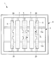
図1には、燃焼バーナ1の正面図が示されている。燃焼バーナ1は、内側に位置する燃料ノズル3と、燃料ノズル3を取り囲む燃焼用空気供給ノズル4とを備えている。
燃焼用空気供給ノズル4は、2次空気のみが流通する流路となっており、火炉内に向けて直進するように空気を供給する。すなわち、燃焼用空気供給ノズル4から流出する空気は、燃料ノズル3から流出する燃料ガスと平行に交差しないように流される。なお、図示しないが、燃焼用空気供給ノズル4の外側には、燃焼用空気を供給する燃焼用3次空気ノズルが設けられる。
[第1実施形態]
以下、本発明の第1実施形態について、図1~図3を用いて説明する。
本実施形態の燃焼バーナは、主として石炭をミルで砕いた微粉炭燃料(燃料)を燃焼するものであり、ボイラ(図示せず)に設けられる。燃焼バーナは、煙道に過熱器や蒸発器等の熱交換を備えたボイラに対して複数設けられ、火炉内で火炎を形成する。
図1には、燃焼バーナ1の正面図が示されている。燃焼バーナ1は、内側に位置する燃料ノズル3と、燃料ノズル3を取り囲む燃焼用空気供給ノズル4とを備えている。
燃焼用空気供給ノズル4は、2次空気のみが流通する流路となっており、火炉内に向けて直進するように空気を供給する。すなわち、燃焼用空気供給ノズル4から流出する空気は、燃料ノズル3から流出する燃料ガスと平行に交差しないように流される。なお、図示しないが、燃焼用空気供給ノズル4の外側には、燃焼用空気を供給する燃焼用3次空気ノズルが設けられる。
燃料ノズル3は、図1に示したように、正面視して矩形状の断面を有しており、内部に微粉炭と空気とが混合された燃料ガスが流される。なお、以下の各実施形態において、燃料ガス流れの下流側を単に下流側と言い、燃料ガス流れの上流側を単に上流側と言う。
燃料ノズル3内には、スプリッタ5,6,7が複数本設けられており、本実施形態では5本設けられている。各スプリッタ5,6,7は、長手軸線が燃料ノズル3の下壁部(一壁部)3a側から対向する上壁部(他壁部)3b側へと延在して設けられている。すなわち、各スプリッタ5、6,7が縦方向に設けられた縦スプリッタとなっている。各スプリッタ5,6,7の上下端は、それぞれ支持部材8によって、燃料ノズル3の壁部に対して固定されている。
燃料ノズル3は、スプリッタ5,6,7とともに上下方向に回動可能とされたノズル角度調整機構を備えている。本実施形態では、縦スプリッタとされているので、上下方向にノズル角度の調整を行っても燃料ガスの流れを大きく偏向することがないので好ましい。
なお、スプリッタ5,6,7は、燃料ガス流れを分割する機能を有する部材であり、内部から空気を噴射する機能は備えていない。
燃料ノズル3内には、スプリッタ5,6,7が複数本設けられており、本実施形態では5本設けられている。各スプリッタ5,6,7は、長手軸線が燃料ノズル3の下壁部(一壁部)3a側から対向する上壁部(他壁部)3b側へと延在して設けられている。すなわち、各スプリッタ5、6,7が縦方向に設けられた縦スプリッタとなっている。各スプリッタ5,6,7の上下端は、それぞれ支持部材8によって、燃料ノズル3の壁部に対して固定されている。
燃料ノズル3は、スプリッタ5,6,7とともに上下方向に回動可能とされたノズル角度調整機構を備えている。本実施形態では、縦スプリッタとされているので、上下方向にノズル角度の調整を行っても燃料ガスの流れを大きく偏向することがないので好ましい。
なお、スプリッタ5,6,7は、燃料ガス流れを分割する機能を有する部材であり、内部から空気を噴射する機能は備えていない。
スプリッタは、中央と水平方向における両端に設けられたスリット付きスプリッタ5,6と、中央のスリット付きスプリッタ5の両隣に設けられたスリット無しスプリッタ7とを備えている。このように、スリット付きスプリッタ5,6と隣り合う位置にスリット無しスプリッタ7が配置されている。
スプリッタ5、6,7は、図2に示されているように、燃料ガス流れ方向に幅が拡大する拡幅部10を備えている。また、拡幅部10の上流側には上下方向に延在する板状部11が燃料ガス流れ方向に沿って設けられている。
拡幅部10は、図2のように断面視した場合に略三角形状となっている。中央のスリット付きスプリッタ5とスリット無しスプリッタ7の拡幅部10は、図2のように断面視した場合に両側に広がっている。一方、水平方向における両端に位置するスリット付きスプリッタ6の拡幅部10は、燃料ノズル3の中央側に向けて広がっているが、燃料ノズル3の壁部側には広がっていない。このように両側に位置するスリット付きスプリッタ6の下流側を直線状とすることで、燃料ノズル3の壁面とスリット付きスプリッタ6との間を流れる燃料ガスを燃焼用空気供給ノズル4から流出する空気流側に偏向しないようにしている。これにより、燃料ノズル3の外周側で生じる外部着火を抑制することができる。
拡幅部10は、図2のように断面視した場合に略三角形状となっている。中央のスリット付きスプリッタ5とスリット無しスプリッタ7の拡幅部10は、図2のように断面視した場合に両側に広がっている。一方、水平方向における両端に位置するスリット付きスプリッタ6の拡幅部10は、燃料ノズル3の中央側に向けて広がっているが、燃料ノズル3の壁部側には広がっていない。このように両側に位置するスリット付きスプリッタ6の下流側を直線状とすることで、燃料ノズル3の壁面とスリット付きスプリッタ6との間を流れる燃料ガスを燃焼用空気供給ノズル4から流出する空気流側に偏向しないようにしている。これにより、燃料ノズル3の外周側で生じる外部着火を抑制することができる。
スリット付きスプリッタ5,6の下流端5a,6aは、図2に示されているように、燃料ノズル3の下流端3c位置に揃えられている。スリット無しスプリッタ7の下流端7aは、スリット付きスプリッタ5,6の下流端5a,6aよりも上流側に所定距離Sだけ離間した位置に設けられている。
ここで、所定距離Sは、燃料ノズル3の開口における等価円径をDとすると、0.001D以上1.0D以下、好ましくは0.03D以上0.5D以下、さらに好ましくは0.05D以上0.3D以下とされる。
上記の下限値および上限値は、次の観点から決定される。下限値を下回ると、スリット付きスプリッタ5,6とスリット無しスプリッタ7との距離が近くなりすぎて、これらスプリッタをずらして流路断面積を確保した利点が得られない。一方、上限値を上回ると、スリット無しスプリッタ7によって形成された再循環領域がスリット付きスプリッタ5,6の手前で消滅してしまい、スリット無しスプリッタ7の再循環領域にスリット付きスプリッタ5,6から燃料ガスを案内するという利点が得られない。
なお、図2の矢印Aに示すように、上流側に位置するスリット無しスプリッタ7を燃料ガス流れ方向に移動させて所定距離Sを調整するようにしてもよい。
ここで、所定距離Sは、燃料ノズル3の開口における等価円径をDとすると、0.001D以上1.0D以下、好ましくは0.03D以上0.5D以下、さらに好ましくは0.05D以上0.3D以下とされる。
上記の下限値および上限値は、次の観点から決定される。下限値を下回ると、スリット付きスプリッタ5,6とスリット無しスプリッタ7との距離が近くなりすぎて、これらスプリッタをずらして流路断面積を確保した利点が得られない。一方、上限値を上回ると、スリット無しスプリッタ7によって形成された再循環領域がスリット付きスプリッタ5,6の手前で消滅してしまい、スリット無しスプリッタ7の再循環領域にスリット付きスプリッタ5,6から燃料ガスを案内するという利点が得られない。
なお、図2の矢印Aに示すように、上流側に位置するスリット無しスプリッタ7を燃料ガス流れ方向に移動させて所定距離Sを調整するようにしてもよい。
図1に示されているように、スリット無しスプリッタ7は、下流端7aの幅がスリット無しスプリッタ7の長手軸線(縦方向軸線)の方向に一定とされている。一方、中央のスリット付きスプリッタ5には、下流端5aの幅を部分的に減少させる複数のスリットSLが形成されている。中央のスリット付きスプリッタ5には、両側部にスリットSLが同じ高さ位置で設けられている。これらスリットにより、スリット付きスプリッタ5には、幅広部W1と幅狭部W2が形成されることになる。
図3には、スリットSLの具体的な形状が示されている。スリットSLは、スリット付きスプリッタ5の下流端5aをコの字状に切り欠いている。さらに、スリットSLを形成する上面SL1及び下面SL2は、燃料ガス流れをスプリッタ5の長手軸線方向(本実施形態では上下方向)に偏向させる面とされている。すなわち、上面SL1によって燃料ガス流れは下方向に偏向され、下面SL2によって燃料ガス流れは上方向に偏向される。
図1に示されているように、両端のスリット付きスプリッタ6にも中央のスリット付きスプリッタ5と同様のスリットSLが形成されているが、燃料ノズル3の中央側の辺にのみスリットSLが設けられている。これは、燃料ノズル3の壁部側にもスリットSLを設けると、そこが着火面となり外部着火のおそれがあるからである。
スリットSLは、なるべく燃料ノズル3の中央側で着火ないし保炎が行われるように、スプリッタ5,6の長手方向における中央部に設け、上下の両端部にはスリットSLを設けないことが好ましい。
スリットSLを設ける範囲L1としては、スプリッタ5,6の長さをL0とした場合、L1/L0が0.8以下、好ましくは0.5以下とされる。
スリットSLを設ける範囲L1としては、スプリッタ5,6の長さをL0とした場合、L1/L0が0.8以下、好ましくは0.5以下とされる。
図1に示されているように、スプリッタ5,6,7の長手軸線の上下端には、これらスプリッタ5,6,7と燃料ノズル3の壁部とを分離する整流板15が設けられている。したがって、上側の整流板15によって、スプリッタ5,6,7側を流れる燃料ガスと、燃料ノズル3の上壁部3b側を流れる燃料ガスとが分離される。また、下側の整流板15によって、スプリッタ5,6,7側を流れる燃料ガスと、燃料ノズル3の下壁部3a側を流れる燃料ガスとが分離される。
上記構成の燃焼バーナ1によれば、以下の作用効果を奏する。
スリットSLを設けたスリット付きスプリッタ5,6によって濡れ縁長さを長くすることで、保炎性が向上する。これにより、燃料ノズル3の内部で保炎する内部保炎が強化される。スリット無しスプリッタ7は、拡幅部10の下流に再循環領域を形成することによって保炎機能を有するが、拡幅部10の傾斜面を利用して隣のスリット付きスプリッタ5,6に対して燃料を案内する案内部材としての機能も有する。これにより、スリット付きスプリッタ5,6での内部保炎が更に強化される。このように、スリット付きスプリッタ5,6とスリット無しスプリッタ7との組合せで内部保炎を強化することにより、還元燃焼を促進することでバーナ火炎領域で発生するNOxを低減することができる。
スリットSLを設けたスリット付きスプリッタ5,6によって濡れ縁長さを長くすることで、保炎性が向上する。これにより、燃料ノズル3の内部で保炎する内部保炎が強化される。スリット無しスプリッタ7は、拡幅部10の下流に再循環領域を形成することによって保炎機能を有するが、拡幅部10の傾斜面を利用して隣のスリット付きスプリッタ5,6に対して燃料を案内する案内部材としての機能も有する。これにより、スリット付きスプリッタ5,6での内部保炎が更に強化される。このように、スリット付きスプリッタ5,6とスリット無しスプリッタ7との組合せで内部保炎を強化することにより、還元燃焼を促進することでバーナ火炎領域で発生するNOxを低減することができる。
スリットSLを形成する傾斜面となる上面SL1及び下面SL2によりスプリッタ5,6の長手軸線の方向に燃料ガス流れを偏向させるので、燃料ガス流れを長手軸線方向にも乱すことができ、さらに保炎性能を向上させることができる。特に、スリットSLを構成する各面によってスリットSLを3次元的に形成することができ、保炎性能を向上させることができる。
スプリッタ5,6,7を燃料ガス流れ方向において異なる位置に配置することにより、スプリッタ5,6,7を燃料ガス流れ方向の同じ位置に配置する場合に比べてスプリッタの拡幅部10が占める面積を減少させることができる。これにより、燃料ガスの増速を抑えることで、燃料ガスの流れ方向の下流側に向かう燃料ガスの流速を、上流側に向かう燃料ガスの燃焼速度に近づけることができ、燃料ガスがさらに下流側へ流れる前に、早く着火させることができ、火炎の保炎性を向上させることができる。
燃料ガス流れ上流側に位置するスリット無しスプリッタ7で燃料を下流側のスリット付きスプリッタ5,6の再循環領域に案内し、下流側のスリット付きスプリッタ5,6の着火ないし保炎を強化することができる。このように、微粉炭を案内する機能を主とする場合にはスリット無しスプリッタ7を用いるのが好ましい。
燃料ガス流れ上流側に位置するスリット無しスプリッタ7で燃料を下流側のスリット付きスプリッタ5,6の再循環領域に案内し、下流側のスリット付きスプリッタ5,6の着火ないし保炎を強化することができる。このように、微粉炭を案内する機能を主とする場合にはスリット無しスプリッタ7を用いるのが好ましい。
燃料ノズル3の壁面側とスプリッタ5,6,7とを分離する整流板15を設けることで、スプリッタ5,6,7の上下の端部で着火する外部着火を抑制することができ、より内部での着火ないし保炎を強化することができる。
なお、本実施形態では、スリット無しスプリッタ7を上流側に配置し、スリット付きスプリッタ5,6を下流側に配置することとしたが、この逆、すなわちスリット無しスプリッタ7を下流側に配置し、スリット付きスプリッタ5,6を上流側に配置することとしてもよい。この構成は、早期に着火を図りたい燃料の場合に用いられ、上流側のスリット付きスプリッタ5,6によって早期着火を図り、これらスリット付きスプリッタ5,6で形成された再循環領域にスリット無しスプリッタによって燃料ガスを案内するようにする。
また、図4に示すように、全てのスプリッタをスリット付きスプリッタ5,6としてもよい。このように配置すると、スリット付きスプリッタ5,6が隣り合っており、スリットSLが形成されていない幅広部W1が対向しているので、一方のスプリッタの幅広面に案内された燃料が他方のスプリッタの下流側へと導かれる。このように、隣り合って対向する幅広部W1どうしで燃料を案内し合うので、両方のスプリッタにおいても保炎が強化されることになる。
[第2実施形態]
次に、本発明の第2実施形態について、図5及び図6を用いて説明する。
本実施形態は、第1実施形態に対して、スプリッタ6の角部を除去したテーパ部が形成されている点で相違し、それ以外については同様である。したがって、共通する構成については同一符号を付しその説明を省略する。
図5に示されているように、両端のスリット付きスプリッタ6の燃料ノズル3の中央部側の上下の隅部には、テーパ部(角除去部)20が形成されている。
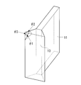
テーパ部20は、角部が除去されていればその形状は問わないが、図6に示すように、角部を形成する3面のそれぞれの頂角θ1,θ2,θ3が除去されるような形状であればよい。したがって、テーパ面のような平面であっても良いし、曲面で構成されていてもよい。
本実施形態では、第1実施形態と異なり、整流板15a,15bが2つ設けられている。各整流板15a,15bは、燃料ノズル3の高さ方向の中央位置から対称とされた高さ位置に設けられており、水平方向に延在する板状体とされている。
次に、本発明の第2実施形態について、図5及び図6を用いて説明する。
本実施形態は、第1実施形態に対して、スプリッタ6の角部を除去したテーパ部が形成されている点で相違し、それ以外については同様である。したがって、共通する構成については同一符号を付しその説明を省略する。
図5に示されているように、両端のスリット付きスプリッタ6の燃料ノズル3の中央部側の上下の隅部には、テーパ部(角除去部)20が形成されている。
テーパ部20は、角部が除去されていればその形状は問わないが、図6に示すように、角部を形成する3面のそれぞれの頂角θ1,θ2,θ3が除去されるような形状であればよい。したがって、テーパ面のような平面であっても良いし、曲面で構成されていてもよい。
本実施形態では、第1実施形態と異なり、整流板15a,15bが2つ設けられている。各整流板15a,15bは、燃料ノズル3の高さ方向の中央位置から対称とされた高さ位置に設けられており、水平方向に延在する板状体とされている。
本実施形態によれば、角部を除去したテーパ部20を形成することとしたので、燃料ノズル3の内周面側からの輻射を受けて角部を起点とする着火が生じ、燃料ノズル3の外周部で発生する外部着火を抑制することができる。
なお、テーパ部(角除去部)20は、他のスプリッタ、すなわち中央のスリット付きスプリッタ5やスリット無しスプリッタ7に設けることとしても良い。
なお、テーパ部(角除去部)20は、他のスプリッタ、すなわち中央のスリット付きスプリッタ5やスリット無しスプリッタ7に設けることとしても良い。
なお、上述した実施形態では、スプリッタの本数を5本としたが、本発明はこれに限定されるものではなく、2~4本であっても、6本以上であっても良い。スプリッタの本数は燃料ノズルの寸法により最適となるよう設計される。
また、上述した各実施形態では、スプリッタ5,6,7が上下方向に延在する縦スプリッタを一例として説明したが、スプリッタ5,6,7が水平方向に延在する横スプリッタに対しても本発明を適用できる。
また、上述した実施形態では、燃料として微粉炭を主に説明したが、これに限定されず、石油コークス、石油残渣物、バイオマス燃料(固形状,スラリ状)についても本発明を適用することができる。
また、上述した各実施形態では、スプリッタ5,6,7が上下方向に延在する縦スプリッタを一例として説明したが、スプリッタ5,6,7が水平方向に延在する横スプリッタに対しても本発明を適用できる。
また、上述した実施形態では、燃料として微粉炭を主に説明したが、これに限定されず、石油コークス、石油残渣物、バイオマス燃料(固形状,スラリ状)についても本発明を適用することができる。
1 燃焼バーナ
3 燃料ノズル
4 燃焼用空気供給ノズル
5 スリット付きスプリッタ
6 スリット付きスプリッタ
7 スリット無しスプリッタ
10 拡幅部
15 整流板
20 テーパ部(角除去部)
3 燃料ノズル
4 燃焼用空気供給ノズル
5 スリット付きスプリッタ
6 スリット付きスプリッタ
7 スリット無しスプリッタ
10 拡幅部
15 整流板
20 テーパ部(角除去部)
Claims (7)
- 燃料と空気とを混合した燃料ガスを火炉内に吹き込む燃料ノズルと、
該燃料ノズル内の先端側に、長手軸線が該燃料ノズルの一壁部側から対向する他壁部側へと延在して設けられ、燃料ガス流れ方向に幅が拡大する拡幅部によって燃料ガス流れを分割する複数のスプリッタと、
を備え、
前記スプリッタは、前記拡幅部の燃料ガス流れ下流端の幅を部分的に減少させるスリットが形成されたスリット付きスプリッタと、該スリット付きスプリッタの隣に配置され、前記拡幅部の燃料ガス流れの下流端の幅が前記長手軸線の方向に一定とされたスリット無しスプリッタと有している燃焼バーナ。 - 燃料と空気とを混合した燃料ガスを火炉内に吹き込む燃料ノズルと、
該燃料ノズル内の先端側に、長手軸線が該燃料ノズルの一壁部側から対向する他壁部側へと延在して設けられ、燃料ガス流れ方向に幅が拡大する拡幅部によって燃料ガス流れを分割する複数のスプリッタと、
を備え、
前記スプリッタは、前記拡幅部の燃料ガス流れ下流端の幅を部分的に減少させるスリットが形成された複数のスリット付きスプリッタを有し、
隣り合う各前記スリット付きスプリッタは、それぞれの前記拡幅部の前記スリットが形成されていない幅広面が対向している燃焼バーナ。 - 前記スリット付きスプリッタの前記スリットを形成する面が、燃料ガス流れを前記長手軸線の方向に偏向させる傾斜面とされている請求項1又は2に記載の燃焼バーナ。
- 前記スプリッタは、燃料ガス流れ方向において異なる位置に配置されている請求項1から3のいずれかに記載の燃焼バーナ。
- 前記スプリッタの前記長手方向における端部には、前記燃料ノズルの壁面側と前記スプリッタとを分離する整流板が設けられている請求項1から4のいずれかに記載の燃焼バーナ。
- 前記スプリッタの拡幅部の下流端における隅部には、角部が除去された角除去部が形成されている請求項1から5のいずれかに記載の燃焼バーナ。
- 火炉と、
該火炉に設けられた請求項1から請求項6のいずれかに記載の燃焼バーナと、
前記火炉の下流側に設けられた煙道と、
該煙道に設けられた熱交換器と、
を有するボイラ。
Priority Applications (7)
| Application Number | Priority Date | Filing Date | Title |
|---|---|---|---|
| RU2017145603A RU2682234C1 (ru) | 2015-09-11 | 2016-08-01 | Горелка для сжигания и котел, снабженный данной горелкой |
| KR1020197026894A KR102297896B1 (ko) | 2015-09-11 | 2016-08-01 | 연소 버너 및 이것을 구비한 보일러 |
| MX2017016352A MX390580B (es) | 2015-09-11 | 2016-08-01 | Quemador de combustion y caldera equipada con el mismo |
| EP16844082.4A EP3299714A4 (en) | 2015-09-11 | 2016-08-01 | Combustion burner and boiler provided with same |
| CN201680037949.6A CN107709881B (zh) | 2015-09-11 | 2016-08-01 | 燃烧器及具备该燃烧器的锅炉 |
| KR1020177036865A KR20180010246A (ko) | 2015-09-11 | 2016-08-01 | 연소 버너 및 이것을 구비한 보일러 |
| US15/736,108 US10677457B2 (en) | 2015-09-11 | 2016-08-01 | Combustion burner and boiler equipped with the same |
Applications Claiming Priority (2)
| Application Number | Priority Date | Filing Date | Title |
|---|---|---|---|
| JP2015-179764 | 2015-09-11 | ||
| JP2015179764A JP6642912B2 (ja) | 2015-09-11 | 2015-09-11 | 燃焼バーナ及びこれを備えたボイラ |
Publications (1)
| Publication Number | Publication Date |
|---|---|
| WO2017043218A1 true WO2017043218A1 (ja) | 2017-03-16 |
Family
ID=58239376
Family Applications (1)
| Application Number | Title | Priority Date | Filing Date |
|---|---|---|---|
| PCT/JP2016/072564 Ceased WO2017043218A1 (ja) | 2015-09-11 | 2016-08-01 | 燃焼バーナ及びこれを備えたボイラ |
Country Status (9)
| Country | Link |
|---|---|
| US (1) | US10677457B2 (ja) |
| EP (1) | EP3299714A4 (ja) |
| JP (1) | JP6642912B2 (ja) |
| KR (2) | KR20180010246A (ja) |
| CN (1) | CN107709881B (ja) |
| CL (1) | CL2017003438A1 (ja) |
| MX (1) | MX390580B (ja) |
| RU (1) | RU2682234C1 (ja) |
| WO (1) | WO2017043218A1 (ja) |
Cited By (1)
| Publication number | Priority date | Publication date | Assignee | Title |
|---|---|---|---|---|
| JP2019132565A (ja) * | 2018-02-01 | 2019-08-08 | 三菱日立パワーシステムズ株式会社 | 燃焼バーナ及びボイラ |
Families Citing this family (1)
| Publication number | Priority date | Publication date | Assignee | Title |
|---|---|---|---|---|
| JP7039792B2 (ja) * | 2017-12-21 | 2022-03-23 | 三菱重工業株式会社 | 燃焼バーナ、これを備えたボイラ及び燃焼バーナの組立方法 |
Citations (6)
| Publication number | Priority date | Publication date | Assignee | Title |
|---|---|---|---|---|
| JPS59205510A (ja) * | 1983-04-22 | 1984-11-21 | コンバツシヨン・エンヂニアリング・インコ−ポレ−テツド | バ−ナのノズルチツプ |
| US5483906A (en) * | 1993-10-26 | 1996-01-16 | Rolls-Royce Power Engineering Plc | Relating to solid fuel burners |
| JPH09203505A (ja) * | 1996-01-29 | 1997-08-05 | Babcock Hitachi Kk | 固体燃料用バーナと固体燃焼システム |
| US6089171A (en) * | 1996-07-08 | 2000-07-18 | Combustion Engineering, Inc. | Minimum recirculation flame control (MRFC) pulverized solid fuel nozzle tip |
| JP2009204256A (ja) * | 2008-02-28 | 2009-09-10 | Mitsubishi Heavy Ind Ltd | 微粉炭バーナ |
| US20090277364A1 (en) * | 2008-03-07 | 2009-11-12 | Alstom Technology Ltd | LOW NOx NOZZLE TIP FOR A PULVERIZED SOLID FUEL FURNACE |
Family Cites Families (66)
| Publication number | Priority date | Publication date | Assignee | Title |
|---|---|---|---|---|
| US2360548A (en) | 1944-10-17 | Combustion method | ||
| US766494A (en) | 1902-12-17 | 1904-08-02 | Francis G Crone | Gas and air mixing burner. |
| US1103253A (en) | 1910-10-24 | 1914-07-14 | Horatio S Bennett | Burner. |
| US1887330A (en) | 1929-11-15 | 1932-11-08 | William S Shaw | Gas burner |
| US2149980A (en) | 1937-11-04 | 1939-03-07 | Jr Henry Wilbur Paret | Method and apparatus for controlling furnace combustion |
| US2259010A (en) | 1939-05-24 | 1941-10-14 | William F Doyle | Apparatus for combustion of fluid fuel |
| US2895435A (en) | 1954-03-15 | 1959-07-21 | Combustion Eng | Tilting nozzle for fuel burner |
| US3112988A (en) | 1960-02-26 | 1963-12-03 | Sheil Oil Company | Mixing gases at supersonic velocity |
| US3213919A (en) | 1962-05-14 | 1965-10-26 | Calzolari Roberto | Nozzle apparatus for burning fuel |
| US3209811A (en) | 1963-03-28 | 1965-10-05 | Loftus Engineering Corp | Combination high velocity burner |
| US3823875A (en) | 1973-08-24 | 1974-07-16 | T Bauer | Burner nozzle tip for pulverized coal and method for its production |
| US4284402A (en) | 1979-05-02 | 1981-08-18 | Atlantic Richfield Company | Flame modifier to reduce NOx emissions |
| DE8005891U1 (de) | 1980-03-01 | 1981-10-01 | Joh. Vaillant Gmbh U. Co, 5630 Remscheid | Mit einem gasluftgemisch gespeister vormischbrenner geringer schalleistung |
| JPS599414A (ja) | 1982-07-08 | 1984-01-18 | Babcock Hitachi Kk | 低窒素酸化物燃焼装置 |
| US4520739A (en) | 1982-07-12 | 1985-06-04 | Combustion Engineering, Inc. | Nozzle tip for pulverized coal burner |
| JPS5977206A (ja) | 1982-10-25 | 1984-05-02 | Babcock Hitachi Kk | 燃焼装置 |
| US4634054A (en) * | 1983-04-22 | 1987-01-06 | Combustion Engineering, Inc. | Split nozzle tip for pulverized coal burner |
| JPS60103207A (ja) | 1983-11-10 | 1985-06-07 | Mitsubishi Heavy Ind Ltd | コ−ルバ−ナノズル |
| JP2791029B2 (ja) | 1988-02-23 | 1998-08-27 | バブコツク日立株式会社 | 微粉炭バーナ |
| US5292246A (en) | 1988-05-02 | 1994-03-08 | Institut Francais Du Petrole | Burner for the manufacture of synthetic gas comprising a solid element with holes |
| EP0445938B1 (en) | 1990-03-07 | 1996-06-26 | Hitachi, Ltd. | Pulverized coal burner, pulverized coal boiler and method of burning pulverized coal |
| JP2954659B2 (ja) | 1990-05-21 | 1999-09-27 | バブコツク日立株式会社 | 微粉炭バーナ |
| US5215259A (en) | 1991-08-13 | 1993-06-01 | Sure Alloy Steel Corporation | Replaceable insert burner nozzle |
| US5529000A (en) | 1994-08-08 | 1996-06-25 | Combustion Components Associates, Inc. | Pulverized coal and air flow spreader |
| JPH08135919A (ja) | 1994-11-11 | 1996-05-31 | Babcock Hitachi Kk | 燃焼装置 |
| DE19539246A1 (de) | 1995-10-21 | 1997-04-24 | Asea Brown Boveri | Airblast-Zerstäuberdüse |
| US6003793A (en) | 1995-12-22 | 1999-12-21 | Mann; Jeffrey S. | Boundary layer coal nozzle assembly for steam generation apparatus |
| CN2281479Y (zh) | 1996-11-18 | 1998-05-13 | 浙江大学 | 宽调节比、多煤种、浓稀相煤粉旋流燃烧装置 |
| JP3448190B2 (ja) | 1997-08-29 | 2003-09-16 | 三菱重工業株式会社 | ガスタービンの燃焼器 |
| JPH11281010A (ja) | 1998-03-26 | 1999-10-15 | Babcock Hitachi Kk | 固体燃料燃焼バーナと固体燃料燃焼装置 |
| FR2784449B1 (fr) | 1998-10-13 | 2000-12-29 | Stein Heurtey | Bruleur a combustible fluide notamment pour fours de rechauffage de produits siderurgiques |
| FR2790309B1 (fr) | 1999-02-25 | 2001-05-11 | Stein Heurtey | Perfectionnements apportes aux bruleurs a flamme plate |
| CN2415254Y (zh) | 2000-02-25 | 2001-01-17 | 华中理工大学 | 带整流板的钝体燃烧器 |
| US6579085B1 (en) | 2000-05-05 | 2003-06-17 | The Boc Group, Inc. | Burner and combustion method for the production of flame jet sheets in industrial furnaces |
| CN1407274A (zh) | 2001-09-05 | 2003-04-02 | 清华同方股份有限公司 | 一种煤粉直流燃烧器 |
| US7163392B2 (en) | 2003-09-05 | 2007-01-16 | Feese James J | Three stage low NOx burner and method |
| US7500849B2 (en) | 2004-01-16 | 2009-03-10 | Air Products And Chemicals, Inc. | Emulsion atomizer nozzle, and burner, and method for oxy-fuel burner applications |
| NO324171B1 (no) | 2006-01-11 | 2007-09-03 | Ntnu Technology Transfer As | Metode for forbrenning av gass, samt gassbrenner |
| FR2899313B1 (fr) | 2006-03-31 | 2008-05-09 | Huau Christian Bernard Louis | Bruleur polyvalent a flamme creuse pour hydrocarbures |
| KR101285447B1 (ko) | 2006-09-27 | 2013-07-12 | 바브콕-히다찌 가부시끼가이샤 | 버너, 버너를 구비한 연소장치 및 보일러 |
| US20080206696A1 (en) | 2007-02-28 | 2008-08-28 | Wark Rickey E | Tilt nozzle for coal-fired burner |
| EP1985926B1 (en) | 2007-04-26 | 2018-09-05 | Mitsubishi Hitachi Power Systems, Ltd. | Combustion equipment and combustion method |
| KR101129628B1 (ko) | 2007-05-30 | 2012-03-27 | 타이요 닛폰 산소 가부시키가이샤 | 무기질 구상화입자 제조용 버너 |
| CN101363624B (zh) | 2007-08-06 | 2011-05-25 | 国际壳牌研究有限公司 | 燃烧器 |
| DE102007040890A1 (de) | 2007-08-29 | 2009-03-05 | Siemens Ag | Kohlenstaubkombinationsbrenner mit integriertem Pilotbrenner |
| US7775791B2 (en) | 2008-02-25 | 2010-08-17 | General Electric Company | Method and apparatus for staged combustion of air and fuel |
| US8104412B2 (en) | 2008-08-21 | 2012-01-31 | Riley Power Inc. | Deflector device for coal piping systems |
| CN201302156Y (zh) | 2008-11-07 | 2009-09-02 | 浙江大学 | 一种外燃式微油点火和超低负荷稳燃煤粉燃烧器 |
| JP5535522B2 (ja) | 2009-05-22 | 2014-07-02 | 三菱重工業株式会社 | 石炭焚ボイラ |
| JP5374404B2 (ja) | 2009-12-22 | 2013-12-25 | 三菱重工業株式会社 | 燃焼バーナおよびこの燃焼バーナを備えるボイラ |
| DE102010004787B4 (de) | 2010-01-16 | 2014-02-13 | Lurgi Gmbh | Verfahren und Brenner zur Herstellung von Synthesegas |
| JP2012122653A (ja) | 2010-12-07 | 2012-06-28 | Mitsubishi Heavy Ind Ltd | 燃焼バーナ |
| US8915731B2 (en) | 2010-12-30 | 2014-12-23 | L'air Liquide Societe Anonyme Pour L'etude Et L'exploitation Des Procedes Georges Claude | Flameless combustion burner |
| JP5490924B2 (ja) | 2011-01-21 | 2014-05-14 | バブコック日立株式会社 | 固体燃料バーナおよび前記バーナを用いる燃焼装置 |
| CN102620291B (zh) | 2011-01-31 | 2014-09-24 | 中国科学院过程工程研究所 | 低氮氧化物排放煤粉解耦燃烧器及煤粉解耦燃烧方法 |
| EP3018407A1 (en) | 2011-04-01 | 2016-05-11 | Mitsubishi Heavy Industries, Ltd. | Solid-fuel-combustion burner, solid-fuel-combustion boiler |
| JP5763389B2 (ja) * | 2011-04-01 | 2015-08-12 | 三菱重工業株式会社 | 燃焼バーナ |
| JP5778499B2 (ja) * | 2011-06-22 | 2015-09-16 | 三菱重工業株式会社 | 固体燃料焚きバーナ及び固体燃料焚きボイラ |
| JP5670804B2 (ja) * | 2011-04-01 | 2015-02-18 | 三菱重工業株式会社 | 燃焼バーナ |
| JP5897363B2 (ja) | 2012-03-21 | 2016-03-30 | 川崎重工業株式会社 | 微粉炭バイオマス混焼バーナ |
| CN202938290U (zh) | 2012-11-05 | 2013-05-15 | 徐州燃控科技股份有限公司 | 一种内燃式兼多通道低氮燃烧器 |
| CN104100969B (zh) | 2013-04-12 | 2017-04-12 | 气体产品与化学公司 | 宽焰氧‑固体燃料喷燃器 |
| CN103267282B (zh) | 2013-06-11 | 2016-05-11 | 牛博申 | 浓淡分离煤粉燃烧器 |
| CN103672883B (zh) | 2013-12-21 | 2017-02-22 | 哈尔滨锅炉厂有限责任公司 | 栅格式旋流燃烧器 |
| CN203718765U (zh) | 2014-02-10 | 2014-07-16 | 四川川锅锅炉有限责任公司 | 一种带三次风低NOx燃烧器 |
| JP5901737B2 (ja) * | 2014-12-18 | 2016-04-13 | 三菱重工業株式会社 | 燃焼バーナ |
-
2015
- 2015-09-11 JP JP2015179764A patent/JP6642912B2/ja active Active
-
2016
- 2016-08-01 KR KR1020177036865A patent/KR20180010246A/ko not_active Ceased
- 2016-08-01 KR KR1020197026894A patent/KR102297896B1/ko active Active
- 2016-08-01 CN CN201680037949.6A patent/CN107709881B/zh active Active
- 2016-08-01 US US15/736,108 patent/US10677457B2/en active Active
- 2016-08-01 WO PCT/JP2016/072564 patent/WO2017043218A1/ja not_active Ceased
- 2016-08-01 RU RU2017145603A patent/RU2682234C1/ru active
- 2016-08-01 EP EP16844082.4A patent/EP3299714A4/en not_active Withdrawn
- 2016-08-01 MX MX2017016352A patent/MX390580B/es unknown
-
2017
- 2017-12-28 CL CL2017003438A patent/CL2017003438A1/es unknown
Patent Citations (6)
| Publication number | Priority date | Publication date | Assignee | Title |
|---|---|---|---|---|
| JPS59205510A (ja) * | 1983-04-22 | 1984-11-21 | コンバツシヨン・エンヂニアリング・インコ−ポレ−テツド | バ−ナのノズルチツプ |
| US5483906A (en) * | 1993-10-26 | 1996-01-16 | Rolls-Royce Power Engineering Plc | Relating to solid fuel burners |
| JPH09203505A (ja) * | 1996-01-29 | 1997-08-05 | Babcock Hitachi Kk | 固体燃料用バーナと固体燃焼システム |
| US6089171A (en) * | 1996-07-08 | 2000-07-18 | Combustion Engineering, Inc. | Minimum recirculation flame control (MRFC) pulverized solid fuel nozzle tip |
| JP2009204256A (ja) * | 2008-02-28 | 2009-09-10 | Mitsubishi Heavy Ind Ltd | 微粉炭バーナ |
| US20090277364A1 (en) * | 2008-03-07 | 2009-11-12 | Alstom Technology Ltd | LOW NOx NOZZLE TIP FOR A PULVERIZED SOLID FUEL FURNACE |
Non-Patent Citations (1)
| Title |
|---|
| See also references of EP3299714A4 * |
Cited By (3)
| Publication number | Priority date | Publication date | Assignee | Title |
|---|---|---|---|---|
| JP2019132565A (ja) * | 2018-02-01 | 2019-08-08 | 三菱日立パワーシステムズ株式会社 | 燃焼バーナ及びボイラ |
| WO2019150663A1 (ja) * | 2018-02-01 | 2019-08-08 | 三菱日立パワーシステムズ株式会社 | 燃焼バーナ及びボイラ |
| CN111656096A (zh) * | 2018-02-01 | 2020-09-11 | 三菱日立电力系统株式会社 | 燃烧炉及锅炉 |
Also Published As
| Publication number | Publication date |
|---|---|
| EP3299714A1 (en) | 2018-03-28 |
| JP6642912B2 (ja) | 2020-02-12 |
| KR20190108651A (ko) | 2019-09-24 |
| KR102297896B1 (ko) | 2021-09-03 |
| CN107709881B (zh) | 2021-12-28 |
| JP2017053601A (ja) | 2017-03-16 |
| EP3299714A4 (en) | 2018-07-18 |
| RU2682234C1 (ru) | 2019-03-15 |
| MX390580B (es) | 2025-03-20 |
| MX2017016352A (es) | 2018-05-02 |
| KR20180010246A (ko) | 2018-01-30 |
| US10677457B2 (en) | 2020-06-09 |
| US20180195715A1 (en) | 2018-07-12 |
| CN107709881A (zh) | 2018-02-16 |
| CL2017003438A1 (es) | 2018-04-20 |
Similar Documents
| Publication | Publication Date | Title |
|---|---|---|
| AU2007301377B2 (en) | Burner, and combustion equipment and boiler comprising burner | |
| US9671108B2 (en) | Combustion burner, solid-fuel-combustion burner, solid-fuel-combustion boiler, boiler, and method for operating boiler | |
| JP6408134B2 (ja) | 燃焼バーナ及びボイラ | |
| JP6632841B2 (ja) | 燃焼バーナ及びこれを備えたボイラ | |
| WO2017043218A1 (ja) | 燃焼バーナ及びこれを備えたボイラ | |
| KR102339292B1 (ko) | 저녹스 버너 | |
| JP5797238B2 (ja) | 燃料バーナ及び旋回燃焼ボイラ | |
| JP5566317B2 (ja) | 固体燃料バーナ | |
| CN107250668A (zh) | 燃烧器以及具备该燃烧器的锅炉 | |
| JP2016156530A (ja) | 燃焼バーナ、ボイラ、及び燃料ガスの燃焼方法 | |
| JP7295990B1 (ja) | ガスバーナ | |
| WO2016158473A1 (ja) | 燃焼バーナ及びボイラ | |
| JP2017142042A (ja) | 燃焼バーナ及び燃焼装置並びにボイラ | |
| JP7046579B2 (ja) | 燃焼バーナ及びこれを備えたボイラ | |
| JP6049814B2 (ja) | 固体燃料焚きバーナ及び固体燃料焚きボイラ | |
| JP6049815B2 (ja) | 固体燃料焚きバーナ及び固体燃料焚きボイラ | |
| JP6797714B2 (ja) | 燃焼装置 | |
| CN111602005B (zh) | 燃烧炉及燃烧装置以及锅炉 | |
| CN111656096A (zh) | 燃烧炉及锅炉 | |
| JP2017142041A (ja) | 燃焼バーナ及び燃焼装置並びにボイラ |
Legal Events
| Date | Code | Title | Description |
|---|---|---|---|
| 121 | Ep: the epo has been informed by wipo that ep was designated in this application |
Ref document number: 16844082 Country of ref document: EP Kind code of ref document: A1 |
|
| WWE | Wipo information: entry into national phase |
Ref document number: MX/A/2017/016352 Country of ref document: MX |
|
| ENP | Entry into the national phase |
Ref document number: 20177036865 Country of ref document: KR Kind code of ref document: A |
|
| NENP | Non-entry into the national phase |
Ref country code: DE |