WO2017043415A1 - シール部材の組付構造及び組付方法、シール部材、ガスタービン - Google Patents
シール部材の組付構造及び組付方法、シール部材、ガスタービン Download PDFInfo
- Publication number
- WO2017043415A1 WO2017043415A1 PCT/JP2016/075696 JP2016075696W WO2017043415A1 WO 2017043415 A1 WO2017043415 A1 WO 2017043415A1 JP 2016075696 W JP2016075696 W JP 2016075696W WO 2017043415 A1 WO2017043415 A1 WO 2017043415A1
- Authority
- WO
- WIPO (PCT)
- Prior art keywords
- seal member
- combustor
- fitting
- gas turbine
- flange portion
- Prior art date
- Legal status (The legal status is an assumption and is not a legal conclusion. Google has not performed a legal analysis and makes no representation as to the accuracy of the status listed.)
- Ceased
Links
Images







Classifications
-
- F—MECHANICAL ENGINEERING; LIGHTING; HEATING; WEAPONS; BLASTING
- F02—COMBUSTION ENGINES; HOT-GAS OR COMBUSTION-PRODUCT ENGINE PLANTS
- F02C—GAS-TURBINE PLANTS; AIR INTAKES FOR JET-PROPULSION PLANTS; CONTROLLING FUEL SUPPLY IN AIR-BREATHING JET-PROPULSION PLANTS
- F02C7/00—Features, components parts, details or accessories, not provided for in, or of interest apart form groups F02C1/00 - F02C6/00; Air intakes for jet-propulsion plants
- F02C7/28—Arrangement of seals
-
- F—MECHANICAL ENGINEERING; LIGHTING; HEATING; WEAPONS; BLASTING
- F01—MACHINES OR ENGINES IN GENERAL; ENGINE PLANTS IN GENERAL; STEAM ENGINES
- F01D—NON-POSITIVE DISPLACEMENT MACHINES OR ENGINES, e.g. STEAM TURBINES
- F01D11/00—Preventing or minimising internal leakage of working-fluid, e.g. between stages
- F01D11/005—Sealing means between non relatively rotating elements
-
- F—MECHANICAL ENGINEERING; LIGHTING; HEATING; WEAPONS; BLASTING
- F01—MACHINES OR ENGINES IN GENERAL; ENGINE PLANTS IN GENERAL; STEAM ENGINES
- F01D—NON-POSITIVE DISPLACEMENT MACHINES OR ENGINES, e.g. STEAM TURBINES
- F01D11/00—Preventing or minimising internal leakage of working-fluid, e.g. between stages
- F01D11/003—Preventing or minimising internal leakage of working-fluid, e.g. between stages by packing rings; Mechanical seals
-
- F—MECHANICAL ENGINEERING; LIGHTING; HEATING; WEAPONS; BLASTING
- F01—MACHINES OR ENGINES IN GENERAL; ENGINE PLANTS IN GENERAL; STEAM ENGINES
- F01D—NON-POSITIVE DISPLACEMENT MACHINES OR ENGINES, e.g. STEAM TURBINES
- F01D25/00—Component parts, details, or accessories, not provided for in, or of interest apart from, other groups
-
- F—MECHANICAL ENGINEERING; LIGHTING; HEATING; WEAPONS; BLASTING
- F01—MACHINES OR ENGINES IN GENERAL; ENGINE PLANTS IN GENERAL; STEAM ENGINES
- F01D—NON-POSITIVE DISPLACEMENT MACHINES OR ENGINES, e.g. STEAM TURBINES
- F01D9/00—Stators
- F01D9/02—Nozzles; Nozzle boxes; Stator blades; Guide conduits, e.g. individual nozzles
- F01D9/023—Transition ducts between combustor cans and first stage of the turbine in gas-turbine engines; their cooling or sealings
-
- F—MECHANICAL ENGINEERING; LIGHTING; HEATING; WEAPONS; BLASTING
- F02—COMBUSTION ENGINES; HOT-GAS OR COMBUSTION-PRODUCT ENGINE PLANTS
- F02C—GAS-TURBINE PLANTS; AIR INTAKES FOR JET-PROPULSION PLANTS; CONTROLLING FUEL SUPPLY IN AIR-BREATHING JET-PROPULSION PLANTS
- F02C3/00—Gas-turbine plants characterised by the use of combustion products as the working fluid
- F02C3/04—Gas-turbine plants characterised by the use of combustion products as the working fluid having a turbine driving a compressor
-
- F—MECHANICAL ENGINEERING; LIGHTING; HEATING; WEAPONS; BLASTING
- F02—COMBUSTION ENGINES; HOT-GAS OR COMBUSTION-PRODUCT ENGINE PLANTS
- F02C—GAS-TURBINE PLANTS; AIR INTAKES FOR JET-PROPULSION PLANTS; CONTROLLING FUEL SUPPLY IN AIR-BREATHING JET-PROPULSION PLANTS
- F02C7/00—Features, components parts, details or accessories, not provided for in, or of interest apart form groups F02C1/00 - F02C6/00; Air intakes for jet-propulsion plants
-
- F—MECHANICAL ENGINEERING; LIGHTING; HEATING; WEAPONS; BLASTING
- F16—ENGINEERING ELEMENTS AND UNITS; GENERAL MEASURES FOR PRODUCING AND MAINTAINING EFFECTIVE FUNCTIONING OF MACHINES OR INSTALLATIONS; THERMAL INSULATION IN GENERAL
- F16J—PISTONS; CYLINDERS; SEALINGS
- F16J15/00—Sealings
- F16J15/02—Sealings between relatively-stationary surfaces
- F16J15/04—Sealings between relatively-stationary surfaces without packing between the surfaces, e.g. with ground surfaces, with cutting edge
-
- F—MECHANICAL ENGINEERING; LIGHTING; HEATING; WEAPONS; BLASTING
- F05—INDEXING SCHEMES RELATING TO ENGINES OR PUMPS IN VARIOUS SUBCLASSES OF CLASSES F01-F04
- F05D—INDEXING SCHEME FOR ASPECTS RELATING TO NON-POSITIVE-DISPLACEMENT MACHINES OR ENGINES, GAS-TURBINES OR JET-PROPULSION PLANTS
- F05D2220/00—Application
- F05D2220/30—Application in turbines
- F05D2220/32—Application in turbines in gas turbines
-
- F—MECHANICAL ENGINEERING; LIGHTING; HEATING; WEAPONS; BLASTING
- F05—INDEXING SCHEMES RELATING TO ENGINES OR PUMPS IN VARIOUS SUBCLASSES OF CLASSES F01-F04
- F05D—INDEXING SCHEME FOR ASPECTS RELATING TO NON-POSITIVE-DISPLACEMENT MACHINES OR ENGINES, GAS-TURBINES OR JET-PROPULSION PLANTS
- F05D2240/00—Components
- F05D2240/55—Seals
-
- F—MECHANICAL ENGINEERING; LIGHTING; HEATING; WEAPONS; BLASTING
- F05—INDEXING SCHEMES RELATING TO ENGINES OR PUMPS IN VARIOUS SUBCLASSES OF CLASSES F01-F04
- F05D—INDEXING SCHEME FOR ASPECTS RELATING TO NON-POSITIVE-DISPLACEMENT MACHINES OR ENGINES, GAS-TURBINES OR JET-PROPULSION PLANTS
- F05D2260/00—Function
- F05D2260/30—Retaining components in desired mutual position
Definitions
- the present invention is applied to a seal member assembly structure provided between a combustor and a turbine to prevent combustion gas leakage, a method of assembling the seal member, a seal member, and a seal member assembly structure. It relates to a gas turbine.
- a typical gas turbine is composed of a compressor, a combustor and a turbine. Then, the air taken in from the air intake is compressed by the compressor to become high-temperature high-pressure compressed air, and the combustor supplies fuel to the compressed air to burn the high-temperature high-pressure
- the combustion gas working fluid
- each combustor has a downstream end of a combustor transition piece and an upstream end of a shroud in a turbine.
- Upper and lower seals are provided therebetween.
- the combustor is provided with a side seal that partitions adjacent combustors on the side of the combustor basket portion. The upper seal and the lower seal are fitted by the upper flange and the lower flange of the combustor basket and connected by the connecting pin. Therefore, the upper seal, the lower seal, and the side seals prevent the combustion gas from leaking from the gap between the combustion sleeve and the shroud.
- the upper seal and the lower seal are connected by fitting the upper flange and the lower flange of the combustion sleeve.
- the upper seal and the lower seal are disposed between the combustor transition member and the shroud to restrain axial displacement of the gas turbine, and the shroud restricts radial displacement. Therefore, if the displacement in the circumferential direction of the upper seal and the lower seal can not be restrained during the operation of the gas turbine, the upper seal and the lower seal may be displaced, and the leakage of combustion gas may not be prevented.
- the present invention solves the above-mentioned problems, and an assembly structure of a seal member capable of preventing displacement of a seal member to prevent leakage of combustion gas for a long period of time, a method of assembling a seal member,
- An object of the present invention is to provide a seal member and a gas turbine.
- the seal member assembly structure of the present invention for achieving the above object is a seal member assembly structure disposed along a circumferential direction of a gas turbine between a combustor can and a turbine shroud.
- the first flange portion and the first flange portion are provided in a state in which a first flange portion provided on any one of the combustor can and the turbine shroud is fitted to a first fitting portion provided on the seal member.
- a convex portion provided on one of the first fitting portion and a concave portion provided on the other of the first fitting portion, and the convex portion and the concave portion surround the gas turbine of the first fitting portion with respect to the first flange portion. It is characterized in that it prevents movement along the direction.
- the seal member is connected to the combustor can or turbine shroud, and at this time, the first flange portion or the first fitting portion
- the convex part provided in one side will entrap into the recessed part provided in the other. Therefore, although the seal member tends to be displaced in the circumferential direction with respect to the combustor can or the turbine shroud, the displacement of the seal is restricted by the contact between the convex portion and the concave portion. As a result, the leakage of the combustion gas can be prevented for a long time by preventing the positional displacement of the seal member, and the reliability can be improved.
- connection pin passes through the first flange portion and the first fitting portion, so that the seal member is either the combustor can or the turbine shroud. It is characterized by being connected.
- the displacement of the seal member can be regulated by the connection pin by the connection pin passing through the first flange portion and the first fitting portion and the seal member being connected to the combustor can or the turbine shroud.
- the convex portion is protruded to one side in the radial direction of the gas turbine, and the concave portion is recessed to one side in the radial direction of the gas turbine.
- the convex portion and the concave portion are provided with a gap along the circumferential direction of the gas turbine.
- the convex portion and the concave portion are characterized in that surfaces opposed to each other are formed by a curved surface.
- the wear at the time of contact can be reduced by forming the convex portion and the concave portion with a curved surface.
- the first flange portion is engaged with the first fitting portion so that they can not move relative to each other in the axial direction of the gas turbine, and the connection pin is the first By penetrating the flange portion and the first fitting portion, relative movement in the circumferential direction of the gas turbine is impossible.
- the seal member can be properly positioned with respect to the combustor can.
- the seal member is provided with a second fitting portion, and the second flange portion provided on either the combustor cylinder or the turbine shroud is a second fitting. It is characterized in that they can not move relative to each other in the radial direction of the gas turbine by being fitted to the parts.
- the seal member can be properly positioned with respect to the turbine shroud.
- a method of assembling a seal member according to the present invention is a method of assembling a seal member disposed along a circumferential direction of a gas turbine between a combustor can and a turbine shroud, And a convex portion provided on one of the first flange portion and the first fitting portion in the other, and a concave portion provided on the other of the first flange portion and the first fitting portion. And displacing the first fitting portion with respect to the first flange portion along the circumferential direction of the gas turbine with the convex portion and the concave portion.
- the first flange portion of the combustor basket fits into the first fitting portion of the seal member, and the convex portion provided on one of the first flange portion and the first fitting portion enters the concave portion provided on the other There is. Therefore, although the seal member tends to be displaced in the circumferential direction with respect to the combustor can or the turbine shroud, the displacement of the seal is restricted by the contact between the convex portion and the concave portion. As a result, the leakage of the combustion gas can be prevented for a long time by preventing the positional displacement of the seal member, and the reliability can be improved.
- the method of assembling the seal member according to the present invention is characterized in that it has a step of penetrating and fixing the connecting pin between the first flange portion and the first fitting portion.
- the displacement of the seal member can be regulated by the connection pin by fixing the connection pin through the first flange portion and the first fitting portion.
- the seal member according to the present invention is a seal member disposed along the circumferential direction of the gas turbine between the combustor can and the turbine shroud, and any one of the combustor can and the turbine shroud
- the seal member the first flange portion provided on one of the combustor cylinder and the turbine shroud is fitted to the first fitting portion, and the circumferential direction of the first fitting portion with respect to the first flange portion by the locking portion Movement along the road is blocked. Therefore, although the seal member tends to be displaced in the circumferential direction with respect to the combustor can or the turbine shroud, the displacement of the seal is restricted by the contact between the convex portion and the concave portion. As a result, the leakage of the combustion gas can be prevented for a long time by preventing the positional displacement of the seal member, and the reliability can be improved.
- the first flange portion is provided with a through hole through which a connection pin for connecting the first fitting portion passes.
- the displacement of the seal member can be regulated by the connection pin by the connection pin passing through the through hole and connecting the first flange portion and the first fitting portion.
- the locking portion is a convex portion or a concave portion that locks to the first flange portion.
- the structure can be simplified by making the locking portion a convex portion or a concave portion.
- a compressor for compressing air a combustor for mixing and burning the compressed air and the fuel compressed by the compressor, and combustion, and rotational power obtained by the combustion gas generated by the combustor It is characterized by comprising a turbine and the seal member.
- the leakage of the combustion gas can be prevented for a long time by preventing the positional displacement of the seal member, and the reliability can be improved.
- the relative movement between the combustor can or the turbine shroud and the seal is prevented due to the relationship between the convex portion and the concave portion. Therefore, the leakage of the combustion gas can be prevented for a long time by preventing the positional displacement of the seal member, and the reliability can be improved.
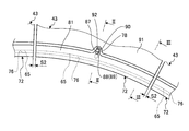
- FIG. 1 is a front view of a seal member showing the assembly structure of the seal member of the first embodiment.
- FIG. 2 is a cross-sectional view taken along the line II-II of FIG.
- FIG. 3 is a cross-sectional view taken along the line III-III of FIG.
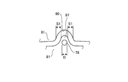
- FIG. 4 is an explanatory view showing the relationship between the convex portion and the concave portion.
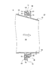
- FIG. 5 is a front view of the seal member showing the operation of the seal member when the connecting pin is broken.
- FIG. 6 is a schematic configuration diagram showing the gas turbine of the first embodiment.
- FIG. 7 is a schematic configuration diagram showing the gas turbine combustor of the first embodiment.
- FIG. 8 is a cross-sectional view showing a connecting structure of a combustor head and a shroud.
- FIG. 9 is a front view of a seal member showing a modification of the assembly structure of the seal member.
- FIG. 10 is a front view of a seal member showing a modification of the assembly structure of the seal member.
- FIG. 11 is a front view of a seal member showing a modification of the assembly structure of the seal member.
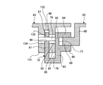
- FIG. 12 is a cross-sectional view of the seal member showing the assembly structure of the seal member of the second embodiment.
- FIG. 13 is a cross-sectional view of the seal member showing the assembly structure of the seal member of the third embodiment.
- First Embodiment 6 is a schematic diagram showing the gas turbine according to the first embodiment
- FIG. 7 is a schematic diagram showing the gas turbine combustor according to the first embodiment
- FIG. 8 is a connecting structure of a combustor tail cylinder and a shroud It is sectional drawing showing.
- the gas turbine 10 is configured of a compressor 11, a combustor 12 and a turbine 13.
- a generator (not shown) is coaxially connected to the gas turbine 10 and can generate electricity.
- the compressor 11 has an air inlet 20 for taking in air, and an inlet guide vane (IGV: Inlet Guide Vane) 22 is disposed in the compressor casing 21, and a plurality of stator vanes 23 and moving blades 24 are provided. They are alternately disposed in the front-rear direction (the axial direction of the rotor 32 described later), and a bleed chamber 25 is provided on the outer side thereof.
- the combustor 12 supplies fuel to the compressed air compressed by the compressor 11 and can be combusted by igniting the fuel.
- a plurality of stationary blades 27 and moving blades 28 are alternately arranged in the front-rear direction (the axial direction of a rotor 32 described later) in a turbine casing 26.
- An exhaust chamber 30 is disposed downstream of the turbine casing 26 via an exhaust casing 29, and the exhaust chamber 30 has an exhaust diffuser 31 continuous with the turbine 13.
- a rotor (rotational shaft) 32 is positioned so as to penetrate the central portion of the compressor 11, the combustor 12, the turbine 13, and the exhaust chamber 30.
- An end of the rotor 32 on the compressor 11 side is rotatably supported by the bearing 33, and an end on the exhaust chamber 30 is rotatably supported by the bearing 34.
- a plurality of disks mounted with the moving blades 24 are stacked and fixed by the compressor 11 and a plurality of disks mounted with the moving blades 28 are stacked and fixed by the turbine 13.
- a drive shaft of a generator (not shown) is connected to the end on the exhaust chamber 30 side.
- the compressor casing 21 of the compressor 11 is supported by the legs 35
- the turbine casing 26 of the turbine 13 is supported by the legs 36
- the exhaust chamber 30 is supported by the legs 37. There is.
- the air taken in from the air intake 20 of the compressor 11 passes through the inlet guide vanes 22, the plurality of stationary vanes 23 and the moving vanes 24 and is compressed to become high temperature / high pressure compressed air.
- a predetermined fuel is supplied to the compressed air and burns.
- the high temperature / high pressure combustion gas that is the working fluid generated by the combustor 12 drives and rotates the rotor 32 by passing through the plurality of stationary blades 27 and the moving blades 28 that constitute the turbine 13.
- the generator connected to 32 is driven.
- the combustion gas which has driven the turbine 13 is released to the atmosphere as exhaust gas.
- the combustor outer cylinder 41 has a combustor inner cylinder 42 supported at a predetermined interval inside, and a combustor tail is formed at the tip of the combustor inner cylinder 42.
- a cylinder (combustor cylinder) 43 is connected to form a combustor casing.
- the combustor internal cylinder 42 has a pilot combustion burner 44 disposed at the center of the interior, and a plurality of mains so as to surround the pilot combustion burner 44 along the circumferential direction on the inner peripheral surface of the combustor internal cylinder 42
- a combustion burner 45 is arranged.
- a bypass pipe 46 is connected to the combustion sleeve 43, and a bypass valve 47 is provided to the bypass pipe 46.
- the air flow path 51 will be formed between both by the base end part of the combustor inner cylinder 42 being mounted
- a pilot combustion burner 44 is disposed at the center of the inside of the combustor inner cylinder 42, and a plurality of main combustion burners 45 are disposed around the same.
- the pilot combustion burner 44 includes a pilot cone 52 supported by the combustor basket 42, a pilot nozzle 53 disposed inside the pilot cone 52, and a swirler (swirler vane) 54 provided on an outer peripheral portion of the pilot nozzle 53. It consists of Each main combustion burner 45 is composed of a burner cylinder 55, a main nozzle 56 disposed inside the burner cylinder 55, and a swirler (swirler vane) 57 provided on the outer peripheral portion of the main nozzle 56.
- a pilot fuel line (not shown) is connected to the fuel port 58 of the pilot nozzle 53, and a main combustion line (not shown) is connected to the fuel port 59 of each main nozzle 56.
- the compressed air flows into the combustor inner cylinder 42, and the compressed air is the main combustion burner in the combustor inner cylinder 42. It mixes with the fuel injected from 45 and becomes a swirling flow of the premixed gas. Further, the compressed air is mixed with the fuel injected from the pilot combustion burner 44, ignited and burned by a not-shown seed fire, and is ejected as a combustion gas into the combustor internal cylinder 42.
- a part of the combustion gas is jetted out so as to be diffused to the surroundings along with the flame in the combustor internal cylinder 42, so that the premixed mixture flows from the main combustion burners 45 into the combustor internal cylinder 42. It is ignited and burns. That is, by the diffusion flame by the pilot fuel injected from the pilot combustion burner 44, it is possible to perform the flame holding for performing the stable combustion of the lean premixed fuel from the main combustion burner 45.
- the combustor transition piece 43 of the combustor 12 and the shrouds (shrouds for turbines) 61 and 62 of the turbine 13 are connected via seal members 71 and 72.
- a plurality of the combustors 12 are arranged in a ring shape along the circumferential direction, and the respective combustor sleeves 43 are supported by the combustor outer cylinder 41 (see FIG. 7).
- the outer shroud 61 and the inner shroud 62 have a ring shape and are supported by the turbine casing 26 (see FIG. 6).
- the seal members 71 and 72 connect the downstream end of the combustor basket 43 and the upstream end of the shrouds 61 and 62 to prevent the outflow of the combustion gas.
- the outer peripheral seal member 71 is disposed along the circumferential direction on the outer side in the radial direction of the gas turbine in the combustor sleeve 43, and the upstream end is connected to the first flange portion 63 on the outer peripheral side of the combustor sleeve 43 The downstream end is connected to the outer peripheral second flange portion 64 of the outer shroud 61.
- the inner peripheral side seal member 72 is disposed along the circumferential direction inward (axial center) in the radial direction of the gas turbine in the combustor tail cylinder 43, and the upstream end portion is an inner peripheral side first end of the combustor tail cylinder 43.
- the downstream end is connected to the inner peripheral second flange portion 66 of the inner shroud 62.
- the combustor sleeve 4 is provided with a side seal (not shown) for partitioning the combustor sleeves 43 whose downstream end portions are adjacent to each other.
- the combustor sleeve 43 has a rectangular cross-sectional shape, and is provided with an outer peripheral first flange portion 63 extending radially outward from the outer peripheral side of the downstream end.
- the outer shroud 61 is provided with a mounting portion 67 extending radially outward from the outer peripheral side of the upstream end portion, and a second outer peripheral side extending from the mounting portion 67 to the upstream side (the combustor tail cylinder 43 side)
- a flange 64 is provided.
- the outer peripheral side seal member 71 is provided with the outer peripheral side first fitting portion 73 opened to the inner peripheral side at the upstream end, and the outer peripheral side opened to the downstream side (the outer shroud 61 side) at the downstream end.
- a second fitting portion 74 is provided.
- the outer peripheral side first flange portion 63 of the combustor sleeve 43 is fitted to the outer peripheral side first fitting portion 73 of the outer peripheral side seal member 71, and the connecting pin 75 is the outer peripheral side first flange portion 63 and the outer peripheral side seal
- the outer peripheral side seal member 71 and the outer shroud 61 are connected by the outer peripheral side second flange portion 64 of the outer shroud 61 being fitted to the outer peripheral side second fitting portion 74 of the outer peripheral side seal member 71.
- the combustor sleeve 43 is provided with an inner peripheral side first flange portion 65 extending radially inward (axial center side) from the inner peripheral side of the downstream end portion.
- the inner shroud 62 is provided with a mounting portion 68 extending radially inward from the inner peripheral side (axial center side) of the upstream end portion, and extends from the mounting portion 68 to the upstream side (combustor tail cylinder 43 side)
- An inner peripheral side second flange portion 66 is provided.
- the inner peripheral seal member 72 is provided with an inner peripheral first fitting portion 76 that opens at the upstream end at the outer peripheral side, and is opened at the downstream end with the downstream side (inner shroud 62 side)
- a circumferential second fitting portion 77 is provided.
- the inner peripheral first flange portion 65 of the combustor sleeve 43 is fitted to the inner peripheral first fitting portion 76 of the inner peripheral seal member 72, and the connecting pin 78 is the inner peripheral first flange portion 65.
- the combustor sleeve 43 and the inner peripheral seal member 72 are connected.
- the inner peripheral side seal member 72 and the inner shroud 62 are connected by the inner peripheral side second flange portion 66 of the inner shroud 62 being fitted to the inner peripheral side second fitting portion 77 of the inner peripheral side seal member 72. Be done.
- the combustion gas flow passage 70 is provided by connecting the combustion sleeve 43 and the shrouds 61 and 62 via the seal members 71 and 72, and the combustion gas flow in the combustion gas flow passage 70 is leaked. Is prevented.
- the outer peripheral side seal is formed by the connection pin 75 penetrating in a state where the outer peripheral side first flange portion 63 is fitted to the outer peripheral side first fitting portion 73 of the outer peripheral side seal member 71.
- the members 71 are connected.
- the combustor sleeve 43 is penetrated by the connection pin 78 penetrating therethrough.
- the circumferential seal member 72 is connected.
- FIG. 1 is a front view of a seal member showing the assembly structure of the seal member of the first embodiment
- FIG. 2 is a sectional view taken along the line II-II in FIG. 1
- FIG. 3 is a sectional view taken along the line III-III in FIG. 4 is an explanatory view showing the relationship between the convex portion and the concave portion
- FIG. 5 is a front view of the seal member showing the operation of the seal member when the connecting pin is broken.
- the combustor sleeve 43 is provided with an inner peripheral first flange portion 65 extending radially inward from the inner peripheral portion of the downstream end.
- the inner peripheral seal member 72 is disposed along the inner peripheral portion of the combustor basket 43, and the inner peripheral first fitting portion 76 is formed by the three fitting walls 81, 82, 83 at the upstream end. Is provided, and the inner peripheral side second fitting portion 77 is provided by the three fitting walls 84, 85 and 86 at the downstream end.
- the inner seal member 72 is provided with a convex portion (locking portion) 87 projecting outward in the radial direction of the gas turbine at an intermediate portion in the longitudinal direction.
- the convex portion 87 is provided so as to protrude outward from the end face of the fitting wall 81, and a circular through hole 88 penetrating in the axial direction is formed in the fitting wall 81 corresponding to the position of the convex portion 87.
- a circular mounting hole 89 which does not penetrate in the axial direction is formed in the fitting wall 83.
- the combustion sleeve 43 has a recess (engagement portion) 90 that is recessed outward in the radial direction of the gas turbine at an intermediate portion in the circumferential direction at the inner periphery.
- the recessed portion 90 is formed by cutting out a part of the block body 91 protruding upstream from the flat surface portion in the inner peripheral side first flange portion 65, and the combustion chamber sleeve 43 is formed on the inner peripheral side first flange portion 65.
- a long hole 92 is formed which is long in the radial direction of the shaft and penetrates in the axial direction.
- the inner peripheral first flange portion 65 of the combustion sleeve 43 is fitted to the inner peripheral first fitting portion 76 of the inner seal member 72, and the connecting pin 78 is inserted into the through hole 88 and the long hole 92.
- the combustor sleeve 43 and the inner peripheral side seal member 72 are connected by penetrating, fitting into the mounting hole 89 and caulking.
- the convex portion 87 of the inner seal member 72 enters the concave portion 90 of the combustor sleeve 43 and overlaps in the radial direction, and the convex portion 87 and the concave portion 90 have a clearance along the circumferential direction of the combustor sleeve 43 It is provided.
- the convex portion 87 protrudes from the end surface of the fitting wall 81 with a curved surface, and the concave portion 90 is cut out with the curved surface of the end surface of the block body 91 of the combustor basket 43. Therefore, the convex part 87 and the recessed part 90 will form the surface which mutually faces by a curved surface.
- the inner peripheral side seal member 72 can not move in the axial direction with respect to the combustor sleeve 43.
- the connecting pin 78 penetrates the inner peripheral first flange portion 65 and the inner peripheral first fitting portion 76, the inner peripheral seal member 72 can not move in the circumferential direction with respect to the combustor sleeve 43. It becomes.
- the connecting pin 78 penetrates the long hole 92 of the inner peripheral side first flange portion 65, the inner peripheral side seal member 72 moves relative to the combustor sleeve 43 by a predetermined amount in the radial direction thereof While becoming possible, it becomes rotatable by a predetermined angle with the connecting pin 78 as a fulcrum. Therefore, the thermal expansion difference between the combustor sleeve 43 and the inner seal member 72 can be absorbed.
- the inner peripheral side seal member 72 can not move in the radial direction with respect to the inner shroud 62. Also in this case, the thermal expansion difference between the combustor sleeve 43 and the inner shroud 62 can be absorbed by the elongated holes 92 of the inner peripheral side first flange portion 65.
- the method of assembling the seal member of the first embodiment is a method of mounting a second seal member disposed along the circumferential direction of the combustor sleeve 43 between the combustor sleeve 43 and the inner shroud 62. And a step of fitting the inner peripheral first flange portion 65 of the combustion sleeve 43 to the inner peripheral first fitting portion 76 of the inner seal member 72, and the inner peripheral side of the inner seal member 72.
- the fitting wall 81 on which the convex portion 87 is formed A clearance is secured between the end face of the block 91 and the end face of the block body 91 in which the recess 90 is formed, and the projection 87 and the recess 90 ensure the operation gap S1 in the circumferential direction of the combustor sleeve 43 ing. Further, since the plurality of combustor sleeves 43 are arranged side by side along the circumferential direction, the gap S2 is formed between the adjacent combustor sleeves 43, that is, between the adjacent inner seal member 72. Is secured.
- the working gap S1 is set smaller than the gap S2 (S1 ⁇ S2).
- the relationship between the operation gaps S1 and S2 is not limited to this magnitude relationship.
- a plurality of connection pins 78 penetrating through the circumferentially adjacent seal members 72 may break during operation. At that time, the plural seal members 72 may move in the circumferential direction by gravity and shift from the proper seal position. In this case, S1 ⁇ S2 is not satisfied, but the unevenness of the seal member 71 is in the middle of the longitudinal direction If it is in the part, the sealing performance can be secured.
- connection pin 78 is broken to release the assembly of the combustor basket 43 and the inner peripheral seal member 72.
- the operation gap S1 is set to be larger than the outer diameter D of the connecting pin 78 (S1> D).
- the relationship between the working gap S1 and the outer diameter D of the connecting pin 78 is not limited to this magnitude relationship.
- the combustor sleeve 43 and the inner seal member 72 are assembled at predetermined positions.
- the projections 87 and the recesses 90 are not in contact with each other.
- the gas turbine is operated.
- the inner seal member 72 tends to be displaced in the circumferential direction with respect to the combustor sleeve 43 and the inner shroud 62.
- the inner peripheral side first flange portion 65 is pulled out from the inner peripheral side first fitting portion 76 by moving the upstream side of the inner peripheral side seal member 72 inward in the radial direction with respect to the combustor sleeve 43.
- the assembly of the combustor sleeve 43 and the inner seal member 72 is released.
- the assembling structure, assembling method, removal method and the like of the combustor sleeve 43, the inner seal member 72 and the inner shroud 62 have been described.
- the combustor sleeve 43 and the outer peripheral seal The assembling structure and the assembling method of the member 71 and the outer shroud 61 are the same. That is, the convex portion of the outer peripheral side first fitting portion 73 of the outer peripheral side sealing member 71 is provided, and the concave portion is provided in the outer peripheral side first flange portion 63 of the combustor sleeve 43; The convex portion is assembled so as to enter the concave portion of the outer peripheral side first flange portion 63.
- the mutually facing surfaces of the convex portion 87 and the concave portion 90 are formed by curved surfaces, but the present invention is not limited to this configuration.
- 9 to 11 are front views of a seal member showing a modification of the assembly structure of the seal member.
- the inner seal member 72 is a convex portion (locking portion) 101 that protrudes outward in the radial direction of the gas turbine at an intermediate portion in the longitudinal direction. Is provided.
- the convex portion 101 protrudes outward from the end face of the fitting wall 81, and is provided in a rectangular shape.
- the combustion sleeve 43 has a recess (locking portion) 102 recessed outward in the radial direction of the gas turbine at an intermediate portion in the circumferential direction at the inner periphery.
- the concave portion 102 is formed in a rectangular shape by cutting out a part of the block body 91 projecting to the upstream side from the flat surface portion in the inner peripheral side first flange portion 65. Then, the inner peripheral first flange portion 65 of the combustor sleeve 43 is fitted to the inner peripheral first fitting portion 76 of the inner seal member 72, and the connection pin 78 is penetrated and fixed. The combustor sleeve 43 and the inner seal member 72 are connected.
- the convex portion 101 of the inner peripheral seal member 72 enters the concave portion 102 of the combustor tail cylinder 43 and overlaps in the radial direction, and the convex portion 101 and the concave portion 102 have a clearance along the circumferential direction of the combustor tail cylinder 43 It is provided.
- convex part 101 and the concave part 102 were made into rectangular shape, it is not limited to this shape, A polygonal shape, such as triangle shape, square shape, trapezoidal shape, may be sufficient, A semicircle and an elliptical shape may be sufficient, It may be in the shape of a circle.
- the inner seal member 72 is provided with a convex portion 87 projecting outward in the radial direction of the gas turbine at an intermediate portion in the longitudinal direction. ing.
- the convex portion 87 is provided so as to protrude outward from the end face of the fitting wall 81.
- the combustor sleeve 43 is provided with a recess (locking portion) 111 that is recessed outward in the radial direction of the gas turbine at an intermediate portion in the circumferential direction at the inner periphery.
- the concave portion 111 is formed by cutting out a part of the block body 112 projecting to the upstream side from the flat surface portion in the inner peripheral side first flange portion 65.
- the block body 112 does not have to be provided on the entire flat portion of the inner peripheral first flange portion 65, and may be provided only on a part in the longitudinal direction, that is, a position facing the convex portion 87.
- the inner peripheral first flange portion 65 of the combustor sleeve 43 is fitted to the inner peripheral first fitting portion 76 of the inner seal member 72, and the connection pin 78 is penetrated and fixed.
- the combustor sleeve 43 and the inner seal member 72 are connected.
- the convex portion 87 of the inner seal member 72 enters the concave portion 111 of the combustor tail cylinder 43 and overlaps in the radial direction, and the convex portion 87 and the concave portion 111 have a clearance along the circumferential direction of the combustor tail cylinder 43 It is provided.
- the inner seal member 72 is a recess (locking portion) 121 recessed inward in the radial direction of the gas turbine at an intermediate portion in the longitudinal direction. Is provided.
- the recess 121 is formed by cutting out a part of the end face of the fitting wall 81.
- the combustion sleeve 43 has a convex portion (locking portion) 122 projecting inward in the radial direction of the gas turbine at an intermediate portion in the circumferential direction at the inner periphery.
- the convex portion 122 is provided so as to protrude inward from the block body 91 which protrudes upstream from the flat surface portion of the inner peripheral side first flange portion 65.
- the inner peripheral first flange portion 65 of the combustion sleeve 43 is fitted to the inner peripheral first fitting portion 76 of the inner peripheral seal member 72, and circumferentially with respect to the concave portion 121 and the convex portion 122
- the connecting pin 78 penetrates and is fixed, whereby the combustor sleeve 43 and the inner peripheral seal member 72 are connected.
- the convex portions 122 of the combustor tail cylinder 43 enter the concave portions 121 of the inner seal member 72 and overlap in the radial direction, and the concave portions 121 and the convex portions 122 have a clearance along the circumferential direction of the combustor tail cylinder 43 It is provided.
- the first fitting portion 73 in which the first flange portions 63 and 65 provided on the combustor basket 43 are provided on the seal members 71 and 72, 76 and the connection pins 75 and 78 pass through the first flange portions 63 and 65 and the first fitting portions 73 and 76, so that the seal members 71 and 72 are connected to the combustor sleeve 43;
- the convex part 87 provided in the fitting parts 73 and 76 is inserted into the concave part 90 provided in the first flange parts 63 and 65.
- the seal members 71 and 72 tend to be displaced in the circumferential direction with respect to the combustor sleeve 43, the displacement of the seal members 71 and 72 is restricted by the contact between the convex portion 87 and the concave portion 90. As a result, by preventing the positional displacement of the seal members 71 and 72, the leakage of the combustion gas can be prevented for a long time, and the reliability can be improved.
- the convex portion 87 protrudes outward in the radial direction of the combustor sleeve 43, and the concave portion 90 is recessed outward in the radial direction of the combustor sleeve 43. ing. Therefore, the convex part 87 and the concave part 90 contact, and the displacement of the seal members 71 and 72 can be easily regulated.
- an operation gap S1 along the circumferential direction of the combustor basket 43 is provided between the convex portion 87 and the concave portion 90. Therefore, when disassembling the combustor sleeve 43 and the seal members 71 and 72, shear force can be applied to the connecting pins 75 and 78 by the amount of the operation gap S1 to break them, thereby improving maintainability. can do.
- the convex portion 87 and the concave portion 90 are formed with curved surfaces facing each other. Therefore, the wear when the convex portion 87 and the concave portion 90 contact can be reduced.
- the first flange portions 63 and 65 can not move relative to each other in the axial direction of the combustor sleeve 43 by fitting to the first fitting portions 73 and 76.
- the connection pins 75 and 78 penetrate the first flange portions 63 and 65 and the first fitting portions 73 and 76, so that they can not move relative to each other in the circumferential direction of the combustor sleeve 43. Therefore, the seal members 71 and 72 can be properly positioned with respect to the combustor basket 43.
- the seal members 71 and 72 are mutually fitted by the second flange portions 64 and 66 provided on the shrouds 61 and 62 being fitted to the second fitting portions 74 and 77. Relative movement is not possible in the radial direction of the shrouds 61 and 62. Therefore, the seal members 71 and 72 can be properly positioned with respect to the shrouds 61 and 62.
- the first flange portions 63, 65 of the combustor basket 43 are fitted to the first fitting portions 73, 76 of the seal members 71, 72. And a step of inserting the convex portion 87 provided in the first fitting portion 73, 76 into the concave portion 90 provided in the first flange portion 63, 65, and the connecting pin 75, 78 with the first flange portion 63, 65 And a step of penetrating and fixing the first fitting portions 73 and 76.
- the seal members 71 and 72 tend to be displaced in the circumferential direction with respect to the combustor sleeve 43, the displacement of the seal members 71 and 72 is restricted by the contact between the convex portion 87 and the concave portion 90. As a result, by preventing the positional displacement of the seal members 71 and 72, the leakage of the combustion gas can be prevented for a long time, and the reliability can be improved.
- a convex portion (locking portion) 87 for blocking movement along the circumferential direction is provided.
- the seal members 71 and 72 tend to be displaced in the circumferential direction with respect to the combustor sleeve 43, the displacement of the seal members 71 and 72 is restricted by the contact between the convex portion 87 and the concave portion 90. As a result, by preventing the positional displacement of the seal members 71 and 72, the leakage of the combustion gas can be prevented for a long time, and the reliability can be improved.
- the compressor 11, the combustor 12, and the turbine 13 are provided. Therefore, the leakage of the combustion gas can be prevented for a long time by preventing the positional displacement of the seal members 71 and 72, and the reliability can be improved.
- FIG. 12 is a cross-sectional view of the seal member showing the assembly structure of the seal member of the second embodiment.
- the members having the same functions as those in the above-described embodiment are denoted by the same reference numerals, and detailed descriptions thereof will be omitted.
- the combustor sleeve 43 is provided with an inner peripheral first flange portion 65 extending inward in the radial direction. Further, in the combustor sleeve 43, an inner peripheral third fitting portion 133 is provided by the inner peripheral first flange portion 65 and the two fitting walls 131 and 132.
- the inner peripheral side seal member 72 is provided with the inner peripheral side first fitting portion 76 by the three fitting walls 81, 82, 83 at the upstream end, and the three ends are fitted at the downstream end
- An inner circumferential second fitting portion 77 is provided by the walls 84, 85, 86.
- the inner seal member 72 is provided with a convex portion 87 projecting outward in the radial direction of the gas turbine at an intermediate portion in the longitudinal direction.
- the convex portion 87 is provided so as to protrude outward from the end face of the fitting wall 81.
- the combustion sleeve 43 has a recess (engagement portion) 90 that is recessed outward in the radial direction of the gas turbine at an intermediate portion in the circumferential direction at the inner periphery.
- the recessed portion 90 is formed by cutting out a part of the fitting wall 132 which protrudes upstream from the flat surface portion of the inner peripheral side first flange portion 65, and the fitting wall 131 and the inner peripheral side first flange portion Long holes 134 and 92 which are long in the radial direction of the combustion sleeve 43 and axially penetrated are formed at 65.
- the inner peripheral first flange portion 65 of the combustor sleeve 43 is fitted to the inner peripheral first fitting portion 76 of the inner peripheral seal member 72, and the fitting wall 81 of the inner peripheral seal member 72 Is fitted into the third inner peripheral fitting portion 133 of the combustion sleeve 43, and the connection pin 78 is fixed through the long hole 134, the through hole 88, and the long hole 92. 43 and the inner peripheral side seal member 72 are connected.
- the convex portion 87 of the inner seal member 72 enters the concave portion 90 of the combustor sleeve 43 and overlaps in the radial direction, and the convex portion 87 and the concave portion 90 have a clearance along the circumferential direction of the combustor sleeve 43 It is provided.
- the inner peripheral side first flange portion 65 of the combustor basket 43 is placed on the inner peripheral side first fitting portion 76 of the inner peripheral side seal member 72.
- the fitting wall 81 of the inner seal member 72 is fitted to the inner third fitting portion 133 of the combustor basket 43 and fixing it by the connecting pin 78.
- the tail cylinder 43 and the inner peripheral seal member 72 are connected. Therefore, the connection rigidity between the combustor sleeve 43 and the inner seal member 72 can be improved.
- FIG. 13 is a cross-sectional view of the seal member showing the assembly structure of the seal member of the third embodiment.
- the members having the same functions as those in the above-described embodiment are denoted by the same reference numerals, and detailed descriptions thereof will be omitted.
- the combustor sleeve 43 and the inner shroud 62 are connected via the inner peripheral seal member 141.
- the inner peripheral seal member 141 connects the downstream end of the combustor basket 43 and the upstream end of the inner shroud 62 to prevent the combustion gas from flowing out.
- the inner peripheral side seal member 141 is disposed along the circumferential direction inward (axial center) in the radial direction of the gas turbine in the combustor tail cylinder 43, and the upstream end portion is an inner peripheral side first end of the combustor tail cylinder 43.
- the downstream end is connected to the inner peripheral second flange portion 152 of the inner shroud 62.
- the combustor sleeve 43 is provided with a mounting portion 153 extending radially inward (axial center side) from the inner peripheral side of the downstream side end portion, and on the downstream side (the inner shroud 62 side) from the mounting portion 153
- An inner peripheral side first flange portion 151 extending is provided.
- the inner shroud 62 is provided with an inner peripheral second flange portion 152 extending from the inner peripheral side (axial center side) of the upstream end to the upstream side (combustor tail cylinder 43 side).
- the inner peripheral side seal member 141 is provided with the inner peripheral side first fitting portion 142 opened at the upstream side end portion to the upstream side (combustor tail cylinder 43 side), and at the downstream side end portion
- An inner peripheral second fitting portion 143 is provided which opens at the shroud 62 side).
- the inner peripheral first flange portion 151 of the combustor sleeve 43 is fitted to the inner peripheral first fitting portion 142 of the inner peripheral seal member 72, and the connecting pin 144 along the radial direction is the inner peripheral first
- the combustor sleeve 43 and the inner peripheral side seal member 141 are connected.
- the inner peripheral second flange portion 152 of the inner shroud 62 is fitted to the inner peripheral second fitting portion 143 of the inner peripheral seal member 72, the inner peripheral seal member 141 and the inner shroud 62 are connected. Be done.
- a radial gap is secured between the inner peripheral first flange portion 151 and the inner peripheral first fitting portion 142, so that the heat of the combustor tail cylinder 43 and the inner peripheral seal member 141 is obtained.
- the expansion difference can be absorbed.
- the inner peripheral side seal member 141 is provided with a convex portion (locking portion) 145 which protrudes to the upstream side of the inner peripheral side first fitting portion 142.
- the combustor sleeve 43 is provided with a recessed portion (engaging portion) 154 recessed on the upstream side at the tip end portion of the mounting portion 153. Then, the inner peripheral first flange portion 151 of the combustor sleeve 43 is fitted to the inner peripheral first fitting portion 142 of the inner seal member 141, and the connection pin 144 is penetrated and fixed. The combustor sleeve 43 and the inner seal member 141 are connected.
- the convex portion 145 of the inner seal member 141 enters the concave portion 154 of the combustor tail cylinder 43 and overlaps in the radial direction, and the convex portion 145 and the concave portion 154 have a clearance along the circumferential direction of the combustor tail cylinder 43 It is provided.
- the first inner peripheral side first flange portion 151 provided on the combustor sleeve 43 is provided on the inner peripheral side seal member 141.
- the inner peripheral side seal member 141 is connected to the combustor sleeve 43 by fitting the fitting portion 142 and the connecting pin 144 penetrating the inner peripheral first flange portion 151 and the inner peripheral first fitting portion 142.
- the convex portion 145 provided on the inner peripheral side first fitting portion 142 is inserted into the concave portion 154 provided on the mounting portion 153.
- the inner seal member 141 tries to be displaced in the circumferential direction with respect to the combustor sleeve 43, the displacement of the inner seal member 141 is restricted by the contact of the convex portion 145 and the concave portion 154. .
- the outer peripheral side first flange portion 63 of the combustor sleeve 43 is fitted to the outer peripheral side first fitting portion 73 of the outer peripheral side sealing member 71, and the connecting pin 75 is the outer peripheral side first flange
- the combustor sleeve 43 and the outer peripheral seal member 71 are connected.
- the inner peripheral first flange portion 65 of the combustor sleeve 43 is fitted to the inner peripheral first fitting portion 76 of the inner peripheral seal member 72
- the connecting pin 78 is an inner peripheral first flange portion 65.
- the combustion sleeve 43 and the inner seal member 72 are connected by penetrating the inner seal member 72.
- the present invention is not limited to this configuration.
- connection pins 75 and 78 may be eliminated.
- the outer peripheral side first fitting portion 73 is fitted to the outer peripheral side first flange portion 63 of the combustor sleeve 43, and the outer peripheral side second flange portion 64 of the outer shroud 61 is an outer peripheral side seal member By being fitted to the outer circumferential side second fitting portion 74, positioning and holding are performed.
- the inner peripheral side first fitting portion 76 is engaged with the inner peripheral side first flange portion 65 of the combustor sleeve 43, and the inner peripheral side second flange portion of the inner shroud 62 Positioning and holding is achieved by fitting the inner peripheral side second fitting portion 77 to the inner peripheral side fitting portion 66.
- the first flanges 63 and 65 provided on the combustor basket 43 are fitted and fixed to the first fitting parts 73 and 76 provided on the seal members 71 and 72, respectively.
- the convex part 87 was provided in 1 fitting part 73,76 and the recessed part 90 was provided in the 1st flange parts 63 and 65, it is not limited to this structure.
- the second flanges 64 and 66 provided on the shrouds 61 and 62 are fitted and fixed to the second fitting parts 74 and 77 provided on the sealing members 71 and 72, and the second fitting parts 74 and 77
- a protrusion may be provided on one of the second flanges 64 and 66, and a recess may be provided on the other.
- the convex portion 87 protrudes outward in the radial direction of the combustor sleeve 43, and the concave portion 90 is recessed outward in the radial direction of the combustor transition rod 43, but the present invention is limited to this configuration. It is not a thing.
- the convex portion may protrude in the axial center direction of the combustor sleeve 43, and the recess may be recessed in the axial center direction of the combustor sleeve 43. That is, it may be provided at such a position as to contact when the convex portion and the concave portion are shifted in the circumferential direction.
Landscapes
- Engineering & Computer Science (AREA)
- General Engineering & Computer Science (AREA)
- Mechanical Engineering (AREA)
- Chemical & Material Sciences (AREA)
- Combustion & Propulsion (AREA)
- Turbine Rotor Nozzle Sealing (AREA)
- Gasket Seals (AREA)
- Gas Burners (AREA)
Abstract
シール部材の組付構造及び組付方法、シール部材、ガスタービンにおいて、燃焼器尾筒43に設けられる第1フランジ部(63,65)がシール部材(71,72)に設けられる第1嵌合部(73,76)に嵌合した状態で、第1フランジ部(63,65)に設けられる凸部(87)が第1嵌合部(73,76)に設けられる凹部(90)に入り込むものである。
Description
本発明は、燃焼器とタービンとの間に設けられて燃焼ガスの漏洩を防止するシール部材の組付構造、このシール部材の組付方法、シール部材、シール部材の組付構造が適用されるガスタービンに関するものである。
一般的なガスタービンは、圧縮機と燃焼器とタービンにより構成されている。そして、空気取入口から取り込まれた空気が圧縮機によって圧縮されることで高温・高圧の圧縮空気となり、燃焼器にて、この圧縮空気に対して燃料を供給して燃焼させることで高温・高圧の燃焼ガス(作動流体)を得て、この燃焼ガスによりタービンを駆動し、このタービンに連結された発電機を駆動する。
このガスタービンにて、燃焼器は、周方向に複数リング状をなして並設されており、各燃焼器は、燃焼器尾筒の下流側端部とタービンにおけるシュラウドの上流側端部との間に上部シール及び下部シールが設けられている。また、燃焼器は、燃焼器尾筒部の側部に、隣接する燃焼器同士を仕切るサイドシールが設けられている。上部シール及び下部シールは、燃焼器尾筒の上部フランジ及び下部フランジが嵌合し、連結ピンにより連結されている。そのため、上部シール及び下部シールと各サイドシールにより、燃焼器尾筒とシュラウドとの隙間からの燃焼ガスの漏洩が防止される。
このようなガスタービンとしては、例えば、下記特許文献に記載されたものがある。
前述したように、上部シール及び下部シールは、燃焼器尾筒の上部フランジ及び下部フランジが嵌合して連結されている。この場合、上部シール及び下部シールは、燃焼器尾筒とシュラウドの間に配置されることでガスタービンの軸心方向の変位が拘束され、シュラウドにより径方向の変位が拘束されている。そのため、ガスタービンの運転中に、上部シール及び下部シールの周方向の変位を拘束できなくなると、上部シール及び下部シールが位置ずれを起こし、燃焼ガスの漏洩を防止できなくなるおそれがある。
本発明は、上述した課題を解決するものであり、シール部材の位置ずれを防止して燃焼ガスの漏洩を長期間にわたって防止することができるシール部材の組付構造、シール部材の組付方法、シール部材、ガスタービンを提供することを目的とする。
上記の目的を達成するための本発明のシール部材の組付構造は、燃焼器用筒とタービン用シュラウドとの間でガスタービンの周方向に沿って配設されるシール部材の組付構造であって、前記燃焼器用筒と前記タービン用シュラウドとのいずれか一方に設けられる第1フランジ部が前記シール部材に設けられる第1嵌合部に嵌合した状態で、前記第1フランジ部と前記第1嵌合部とのいずれか一方に設けられる凸部が他方に設けられる凹部に入り込んでおり、前記凸部及び前記凹部によって前記第1フランジ部に対する前記第1嵌合部の前記ガスタービンの周方向に沿う移動を阻止する、ことを特徴とするものである。
従って、第1フランジ部がシール部材の第1嵌合部に嵌合することで、シール部材が燃焼器用筒またはタービン用シュラウドに連結され、このとき、第1フランジ部または第1嵌合部の一方に設けられる凸部が他方に設けられる凹部に入り込むこととなる。そのため、燃焼器用筒またはタービン用シュラウドに対してシール部材が周方向に変位しようとするが、凸部と凹部が接触することでこのシール部材の変位が規制される。その結果、シール部材の位置ずれを防止することで燃焼ガスの漏洩を長期間にわたって防止することができ、信頼性を向上することができる。
本発明のシール部材の組付構造では、連結ピンが前記第1フランジ部と前記第1嵌合部を貫通することで前記シール部材が前記燃焼器用筒と前記タービン用シュラウドとのいずれか一方に連結されることを特徴としている。
従って、連結ピンが第1フランジ部と第1嵌合部を貫通してシール部材が燃焼器用筒またはタービン用シュラウドに連結されることで、連結ピンによりシール部材の変位を規制することができる。
本発明のシール部材の組付構造では、前記凸部は、前記ガスタービンの径方向における一方側に突出し、前記凹部は、前記ガスタービンの径方向における一方側に凹むことを特徴としている。
従って、ガスタービンの径方向に突出する凸部が径方向に凹む凹部に入り込むことで、凸部と凹部が接触してシール部材の変位を容易に規制することができる。
本発明のシール部材の組付構造では、前記凸部と前記凹部は、前記ガスタービンの周方向に沿う隙間が設けられることを特徴としている。
従って、凸部と凹部におけるガスタービンの周方向に沿って隙間を設けることで、燃焼器用筒とシール部材の組付を解除するとき、この隙間量だけ連結ピンにせん断力を付与して破断することができ、メンテナンス性を向上することができる。
本発明のシール部材の組付構造では、前記凸部と前記凹部は、互いに対向する面が曲面により形成されることを特徴としている。
従って、凸部と凹部を曲面により形成することで、接触時の摩耗を低減することができる。
本発明のシール部材の組付構造では、前記第1フランジ部が前記第1嵌合部に嵌合することで互いに前記ガスタービンの軸方向に相対移動不能であり、前記連結ピンが前記第1フランジ部と前記第1嵌合部を貫通することで互いに前記ガスタービンの周方向に相対移動不能であることを特徴としている。
従って、燃焼器用筒に対してシール部材を適正に位置決めすることができる。
本発明のシール部材の組付構造では、前記シール部材は、第2嵌合部が設けられ、燃焼器用筒とタービン用シュラウドとのいずれか他方に設けられる前記第2フランジ部が第2嵌合部に嵌合することで互いに前記ガスタービンの径方向に相対移動不能であることを特徴としている。
従って、タービン用シュラウドに対してシール部材を適正に位置決めすることができる。
また、本発明のシール部材の組付方法は、燃焼器用筒とタービン用シュラウドとの間でガスタービンの周方向に沿って配設されるシール部材の組付方法であって、前記燃焼器用筒の第1フランジ部を前記シール部材の第1嵌合部に嵌合する工程と、前記第1フランジ部と前記第1嵌合部とのいずれか一方に設けられる凸部を他方に設けられる凹部に入り込ませ、前記凸部及び前記凹部によって前記第1フランジ部に対する前記第1嵌合部の前記ガスタービンの周方向に沿う移動を阻止する工程と、を有することを特徴とするものである。
従って、燃焼器用筒の第1フランジ部がシール部材の第1嵌合部に嵌合し、第1フランジ部と第1嵌合部の一方に設けられる凸部は他方に設けられる凹部に入り込んでいる。そのため、燃焼器用筒またはタービン用シュラウドに対してシール部材が周方向に変位しようとするが、凸部と凹部が接触することでこのシール部材の変位が規制される。その結果、シール部材の位置ずれを防止することで燃焼ガスの漏洩を長期間にわたって防止することができ、信頼性を向上することができる。
本発明のシール部材の組付方法では、連結ピンを前記第1フランジ部と前記第1嵌合部に貫通させて固定する工程を有することを特徴としている。
従って、連結ピンが第1フランジ部と第1嵌合部を貫通して固定されることで、連結ピンによりシール部材の変位を規制することができる。
また、本発明のシール部材は、燃焼器用筒とタービン用シュラウドとの間でガスタービンの周方向に沿って配設されるシール部材であって、前記燃焼器用筒と前記タービン用シュラウドとのいずれか一方に設けられる第1フランジ部が嵌合する第1嵌合部と、前記第1フランジ部に対する前記第1嵌合部の前記ガスタービンの周方向に沿う移動を阻止する係止部と、を有することを特徴とするものである。
従って、シール部材は、燃焼器用筒とタービン用シュラウドの一方に設けられる第1フランジ部が第1嵌合部に嵌合し、係止部により第1フランジ部に対する第1嵌合部の周方向に沿う移動が阻止されている。そのため、燃焼器用筒またはタービン用シュラウドに対してシール部材が周方向に変位しようとするが、凸部と凹部が接触することでこのシール部材の変位が規制される。その結果、シール部材の位置ずれを防止することで燃焼ガスの漏洩を長期間にわたって防止することができ、信頼性を向上することができる。
本発明のシール部材では、前記第1フランジ部に前記第1嵌合部を連結するための連結ピンが貫通する貫通孔が設けられることを特徴としている。
従って、連結ピンが貫通孔を貫通して第1フランジ部と第1嵌合部を連結することで、連結ピンによりシール部材の変位を規制することができる。
本発明のシール部材では、前記係止部は、前記第1フランジ部に係止する凸部または凹部であることを特徴としている。
従って、係止部を凸部または凹部とすることで、構造を簡素化することができる。
また、本発明のガスタービンは、空気を圧縮する圧縮機と、前記圧縮機が圧縮した圧縮空気と燃料を混合して燃焼する燃焼器と、前記燃焼器が生成した燃焼ガスにより回転動力を得るタービンと、前記シール部材と、を備えることを特徴とするものである。
従って、シール部材の位置ずれを防止することで燃焼ガスの漏洩を長期間にわたって防止することができ、信頼性を向上することができる。
本発明のシール部材の組付構造、シール部材の組付方法、シール部材、ガスタービンによれば、凸部と凹部との関係で燃焼器用筒またはタービン用シュラウドとシール部材との相対移動が阻止されるので、シール部材の位置ずれを防止することで燃焼ガスの漏洩を長期間にわたって防止することができ、信頼性を向上することができる。
以下に添付図面を参照して、本発明に係るシール部材の組付構造、シール部材の組付方法、シール部材、ガスタービンの好適な実施形態を詳細に説明する。なお、この実施形態により本発明が限定されるものではなく、また、実施形態が複数ある場合には、各実施形態を組み合わせて構成するものも含むものである。
[第1実施形態]
図6は、第1実施形態のガスタービンを表す概略構成図、図7は、第1実施形態のガスタービン燃焼器を表す概略構成図、図8は、燃焼器尾筒とシュラウドとの連結構造を表す断面図である。
図6は、第1実施形態のガスタービンを表す概略構成図、図7は、第1実施形態のガスタービン燃焼器を表す概略構成図、図8は、燃焼器尾筒とシュラウドとの連結構造を表す断面図である。
第1実施形態において、図6に示すように、ガスタービン10は、圧縮機11と燃焼器12とタービン13により構成されている。このガスタービン10は、同軸上に図示しない発電機が連結されており、発電可能となっている。
圧縮機11は、空気を取り込む空気取入口20を有し、圧縮機車室21内に入口案内翼(IGV:Inlet Guide Vane)22が配設されると共に、複数の静翼23と動翼24が前後方向(後述するロータ32の軸方向)に交互に配設されてなり、その外側に抽気室25が設けられている。燃焼器12は、圧縮機11で圧縮された圧縮空気に対して燃料を供給し、点火することで燃焼可能となっている。タービン13は、タービン車室26内に複数の静翼27と動翼28が前後方向(後述するロータ32の軸方向)に交互に配設されている。このタービン車室26の下流側には、排気車室29を介して排気室30が配設されており、排気室30は、タービン13に連続する排気ディフューザ31を有している。
また、圧縮機11、燃焼器12、タービン13、排気室30の中心部を貫通するようにロータ(回転軸)32が位置している。ロータ32は、圧縮機11側の端部が軸受部33により回転自在に支持される一方、排気室30側の端部が軸受部34により回転自在に支持されている。そして、このロータ32は、圧縮機11にて、各動翼24が装着されたディスクが複数重ねられて固定され、タービン13にて、各動翼28が装着されたディスクが複数重ねられて固定されており、排気室30側の端部に図示しない発電機の駆動軸が連結されている。
そして、このガスタービン10は、圧縮機11の圧縮機車室21が脚部35に支持され、タービン13のタービン車室26が脚部36により支持され、排気室30が脚部37により支持されている。
従って、圧縮機11の空気取入口20から取り込まれた空気が、入口案内翼22、複数の静翼23と動翼24を通過して圧縮されることで高温・高圧の圧縮空気となる。燃焼器12にて、この圧縮空気に対して所定の燃料が供給され、燃焼する。そして、この燃焼器12で生成された作動流体である高温・高圧の燃焼ガスが、タービン13を構成する複数の静翼27と動翼28を通過することでロータ32を駆動回転し、このロータ32に連結された発電機を駆動する。一方、タービン13を駆動した燃焼ガスは、排気ガスとして大気に放出される。
上述した燃焼器12において、図7に示すように、燃焼器外筒41は、内部に所定間隔をあけて燃焼器内筒42が支持され、この燃焼器内筒42の先端部に燃焼器尾筒(燃焼器用筒)43が連結されて燃焼器ケーシングが構成されている。燃焼器内筒42は、内部の中心に位置してパイロット燃焼バーナ44が配置されると共に、燃焼器内筒42の内周面に周方向に沿ってパイロット燃焼バーナ44を取り囲むように複数のメイン燃焼バーナ45が配置されている。また、燃焼器尾筒43はバイパス管46が連結されており、このバイパス管46にバイパス弁47が設けられている。
詳細に説明すると、燃焼器外筒41は、基端部に燃焼器内筒42の基端部が装着されることで、両者の間に空気流路51が形成されている。そして、燃焼器内筒42は、内部の中心に位置してパイロット燃焼バーナ44が配置され、その周囲に複数のメイン燃焼バーナ45が配置されている。
パイロット燃焼バーナ44は、燃焼器内筒42に支持されたパイロットコーン52と、パイロットコーン52の内部に配置されたパイロットノズル53と、パイロットノズル53の外周部に設けられる旋回翼(スワラーベーン)54とから構成されている。また、各メイン燃焼バーナ45は、バーナ筒55と、バーナ筒55の内部に配置されたメインノズル56と、メインノズル56の外周部に設けられる旋回翼(スワラーベーン)57とから構成されている。
また、燃焼器外筒41は、図示しないパイロット燃料ラインがパイロットノズル53の燃料ポート58に連結され、図示しないメイン燃焼ラインが各メインノズル56の燃料ポート59に連結されている。
従って、高温・高圧の圧縮空気の空気流が空気流路51に流れ込むと、この圧縮空気が燃焼器内筒42内に流れ込み、この燃焼器内筒42内にて、この圧縮空気がメイン燃焼バーナ45から噴射された燃料と混合され、予混合気の旋回流となる。また、圧縮空気は、パイロット燃焼バーナ44から噴射された燃料と混合され、図示しない種火により着火されて燃焼し、燃焼ガスとなって燃焼器内筒42内に噴出される。このとき、燃焼ガスの一部が燃焼器内筒42内に火炎を伴って周囲に拡散するように噴出されることで、各メイン燃焼バーナ45から燃焼器内筒42内に流れ込んだ予混合気に着火されて燃焼する。即ち、パイロット燃焼バーナ44から噴射されたパイロット燃料による拡散火炎により、メイン燃焼バーナ45からの希薄予混合燃料の安定燃焼を行うための保炎を行うことができる。
ところで、図8に示すように、燃焼器12の燃焼器尾筒43とタービン13のシュラウド(タービン用シュラウド)61,62は、シール部材71,72を介して連結されている。燃焼器12は、複数が周方向に沿ってリング状に配列されており、各燃焼器尾筒43は、燃焼器外筒41(図7参照)に支持されている。外側シュラウド61と内側シュラウド62は、リング形状をなし、タービン車室26(図6参照)に支持されている。各シール部材71,72は、燃焼器尾筒43の下流側端部と各シュラウド61,62の上流側端部を連結することで、燃焼ガスの外部流出を防止するものである。
なお、以下の説明にて、径方向、周方向、内周側、外周側の各記載は、特定の説明がない限り、ガスタービン10を基準とした方向である。
外周側シール部材71は、燃焼器尾筒43におけるガスタービンの径方向の外側に周方向に沿って配置され、上流側端部が燃焼器尾筒43の外周側第1フランジ部63に連結され、下流側端部が外側シュラウド61の外周側第2フランジ部64に連結されている。内周側シール部材72は、燃焼器尾筒43におけるガスタービンの径方向の内側(軸心側)に周方向に沿って配置され、上流側端部が燃焼器尾筒43の内周側第1フランジ部65に連結され、下流側端部が内側シュラウド62の内周側第2フランジ部66に連結されている。なお、燃焼器尾筒43は、下流側端部が隣接する燃焼器尾筒43同士を仕切るサイドシール(図示略)が設けられている。
燃焼器尾筒43は、矩形断面形状をなし、下流側端部の外周辺側から径方向の外側に延出する外周側第1フランジ部63が設けられている。外側シュラウド61は、上流側端部の外周側から径方向の外側に延出する取付部67が設けられ、取付部67から上流側(燃焼器尾筒43側)に延出する外周側第2フランジ部64が設けられている。一方、外周側シール部材71は、上流側端部に内周側に開口する外周側第1嵌合部73が設けられ、下流側端部に下流側(外側シュラウド61側)に開口する外周側第2嵌合部74が設けられている。
そして、燃焼器尾筒43の外周側第1フランジ部63が外周側シール部材71の外周側第1嵌合部73に嵌合し、連結ピン75が外周側第1フランジ部63及び外周側シール部材71を貫通することで、燃焼器尾筒43と外周側シール部材71が連結される。また、外側シュラウド61の外周側第2フランジ部64が外周側シール部材71の外周側第2嵌合部74に嵌合することで、外周側シール部材71と外側シュラウド61が連結される。
また、燃焼器尾筒43は、下流側端部の内周辺側から径方向の内側(軸心側)に延出する内周側第1フランジ部65が設けられている。内側シュラウド62は、上流側端部の内周側(軸心側)から径方向の内側に延出する取付部68が設けられ、取付部68から上流側(燃焼器尾筒43側)に延出する内周側第2フランジ部66が設けられている。一方、内周側シール部材72は、上流側端部に外周側に開口する内周側第1嵌合部76が設けられ、下流側端部に下流側(内側シュラウド62側)に開口する内周側第2嵌合部77が設けられている。
そして、燃焼器尾筒43の内周側第1フランジ部65が内周側シール部材72の内周側第1嵌合部76に嵌合し、連結ピン78が内周側第1フランジ部65及び内周側シール部材72を貫通することで、燃焼器尾筒43と内周側シール部材72が連結される。また、内側シュラウド62の内周側第2フランジ部66が内周側シール部材72の内周側第2嵌合部77に嵌合することで、内周側シール部材72と内側シュラウド62が連結される。
このように燃焼器尾筒43と各シュラウド61,62が各シール部材71,72を介して連結されることで、燃焼ガス流路70が設けられ、燃焼ガス流路70を流れる燃焼ガスの漏洩が防止されている。
ここで、燃焼器尾筒43は、外周側第1フランジ部63が外周側シール部材71の外周側第1嵌合部73に嵌合した状態で、連結ピン75が貫通することで外周側シール部材71が連結される。また、燃焼器尾筒43は、内周側第1フランジ部65が内周側シール部材72の内周側第1嵌合部76に嵌合した状態で、連結ピン78が貫通することで内周側シール部材72が連結される。そのため、ガスタービンの運転中に、各シール部材71,72における周方向の拘束がなくなり、各シール部材71,72が周方向にずれて隙間が生じ、燃焼ガスの漏洩を防止できなくなるおそれがある。そこで、第1実施形態では、シール部材71,72の周方向の位置ずれを抑制する構造を提供する。
以下、シール部材71,72について詳細に説明するが、ここでは、内周側シール部材72について説明する。図1は、第1実施形態のシール部材の組付構造を表すシール部材の正面図、図2は、図1のII-II断面図、図3は、図1のIII-III断面図、図4は、凸部と凹部の関係を表す説明図、図5は、連結ピン破断時のシール部材の作動を表すシール部材の正面図である。
図1から図3に示すように、燃焼器尾筒43は、下流側端部の内周部から径方向の内側に延出する内周側第1フランジ部65が設けられている。内周側シール部材72は、この燃焼器尾筒43の内周部に沿って配置され、上流側端部に3個の嵌合壁81,82,83により内周側第1嵌合部76が設けられ、下流側端部に3個の嵌合壁84,85,86により内周側第2嵌合部77が設けられている。
また、内周側シール部材72は、長手方向の中間部にガスタービンの径方向の外側に突出する凸部(係止部)87が設けられている。凸部87は、嵌合壁81の端面から外側に突出して設けられており、この凸部87の位置に対応した嵌合壁81に軸心方向に貫通する円形の貫通孔88が形成されると共に嵌合壁83に軸心方向に貫通しない円形の取付穴89が形成されている。一方、燃焼器尾筒43は、内周辺における周方向の中間部にガスタービンの径方向の外側に凹む凹部(係止部)90が設けられている。凹部90は、内周側第1フランジ部65における平面部から上流側に突出するブロック体91の一部が切欠かれて形成されており、内周側第1フランジ部65に燃焼器尾筒43の径方向に長く、軸心方向に貫通する長孔92が形成されている。
そして、燃焼器尾筒43の内周側第1フランジ部65が内周側シール部材72の内周側第1嵌合部76に嵌合し、連結ピン78が貫通孔88及び長孔92を貫通し、取付穴89に嵌入し、かしめられることで、燃焼器尾筒43と内周側シール部材72が連結されている。このとき、内周側シール部材72の凸部87が燃焼器尾筒43の凹部90に入り込んで径方向において重なり、凸部87と凹部90は、燃焼器尾筒43の周方向に沿う隙間が設けられている。即ち、凸部87は、嵌合壁81の端面から曲面をもって突出し、凹部90は、燃焼器尾筒43のブロック体91の端面が曲面をもって切欠かれている。そのため、この凸部87と凹部90は、互いに対向する面が曲面により形成されることとなる。
このとき、内周側第1フランジ部65が内周側第1嵌合部76に嵌合することで、内周側シール部材72が燃焼器尾筒43に対してその軸方向に移動不能となり、連結ピン78が内周側第1フランジ部65と内周側第1嵌合部76を貫通することで、内周側シール部材72が燃焼器尾筒43に対してその周方向に移動不能となる。但し、連結ピン78が内周側第1フランジ部65の長孔92を貫通しているため、内周側シール部材72は、燃焼器尾筒43に対してその径方向に所定量だけ相対移動可能となると共に、連結ピン78を支点として所定角度だけ回動可能となる。そのため、燃焼器尾筒43と内周側シール部材72との熱膨張差を吸収することができる。
また、内周側第2フランジ部66が内周側第2嵌合部77に嵌合することで、内周側シール部材72が内側シュラウド62に対してその径方向に移動不能となる。この場合でも、内周側第1フランジ部65の長孔92により燃焼器尾筒43と内側シュラウド62との熱膨張差を吸収することができる。
ここで、第1実施形態のシール部材の組付方法について説明する。第1実施形態のシール部材の組付方法は、燃焼器尾筒43と内側シュラウド62との間で燃焼器尾筒43の周方向に沿って配設される第2シール部材の取付方法であって、燃焼器尾筒43の内周側第1フランジ部65を内周側シール部材72の内周側第1嵌合部76に嵌合する工程と、内周側シール部材72の内周側第1嵌合部76側に設けられる凸部87を燃焼器尾筒43の内周側第1フランジ部65側に設けられる凹部90に入り込ませる工程と、連結ピン78を内周側第1フランジ部65と内周側第1嵌合部76に貫通させて固定する工程と、内側シュラウド62の内周側第2フランジ部66を内周側シール部材72の内周側第2嵌合部77に嵌合する工程とを有している。
このように燃焼器尾筒43と内側シュラウド62との間に内周側シール部材72が組付けられたとき、図1及び図4に示すように、凸部87が形成される嵌合壁81の端面と、凹部90が形成されるブロック体91の端面との間に隙間が確保されており、凸部87と凹部90とは、燃焼器尾筒43の周方向における作動隙間S1が確保されている。また、複数の燃焼器尾筒43が周方向に沿って並設されていることから、隣接する燃焼器尾筒43との間、つまり、隣接する内周側シール部材72との間に隙間S2が確保されている。そして、作動隙間S1は、隙間S2より小さく(S1<S2)設定されている。なお、作動隙間S1,S2の関係は、この大小関係に限定されるものではない。例えば、周方向に隣接するシール部材72を貫通している連結ピン78が運転中に複数個折れてしまうことがある。そのときに、複数のシール部材72が重力により周方向へ移動して適正なシール位置からずれてしまうことがあり、この場合、S1<S2にならないが、シール部材71の凹凸が長手方向の中間部にありさえすれば、シール性能を確保することができる。
また、燃焼器尾筒43や内周側シール部材72などは、所定の期間を経て交換する必要があり、燃焼器尾筒43や内周側シール部材72を取外す必要がある。この場合、連結ピン78を破断することで燃焼器尾筒43と内周側シール部材72との組付を解除する。具体的には、内周側シール部材72に対して長手方向(燃焼器尾筒43の周方向)の応力を付与することで連結ピン78にせん断力を与えて破断し、燃焼器尾筒43と内周側シール部材72の組付を解除する。そのため、作動隙間S1は、連結ピン78の外径Dより大きく(S1>D)設定されている。なお、作動隙間S1と連結ピン78の外径Dとの関係もこの大小関係に限定されるものではない。
ここで、第1実施形態のシール部材の組付構造の作用について説明する。
図1に示すように、燃焼器尾筒43と内周側シール部材72と内側シュラウド62が組付けられた状態で、燃焼器尾筒43と内周側シール部材72とは所定の位置に組付けられており、凸部87と凹部90は接触していない。この状態で、ガスタービンが運転される。図5に示すように、このガスタービンの運転中に、燃焼器尾筒43及び内側シュラウド62に対して内周側シール部材72が周方向に変位しようとする。ところが、内周側シール部材72が燃焼器尾筒43及び内側シュラウド62に対して作動隙間S1だけ移動すると、凸部87と凹部90に当接(接触)することで、内周側シール部材72の周方向の変位が規制される。その結果、内周側シール部材72の位置ずれが防止される。
また、燃焼器尾筒43と内周側シール部材72と内側シュラウド62の組付を解除する場合、図1に示すように、まず、内周側シール部材72に対して周方向の応力を付与することで、連結ピン78にせん断力を付与して破断する。次に、内側シュラウド62を下流側に移動すると共に、燃焼器尾筒43及び内周側シール部材72を上流側に移動することで、内側シュラウド62の内周側第2フランジ部66を内周側シール部材72の内周側第2嵌合部77から抜き取ることで、内側シュラウド62と内周側シール部材72との組付を解除する。そして、燃焼器尾筒43に対して内周側シール部材72の上流側を径方向の内側に移動することで、内周側第1フランジ部65を内周側第1嵌合部76から抜き取ると共に、凸部87を凹部90から抜き取ることで、燃焼器尾筒43と内周側シール部材72との組付を解除する。
なお、上述の説明では、燃焼器尾筒43と内周側シール部材72と内側シュラウド62の組付構造、組付方法、取外方法などについて説明したが、燃焼器尾筒43と外周側シール部材71と外側シュラウド61の組付構造及び組付方法も同様である。即ち、外周側シール部材71の外周側第1嵌合部73の凸部が設けられ、燃焼器尾筒43の外周側第1フランジ部63に凹部を設け、外周側第1嵌合部73の凸部が外周側第1フランジ部63の凹部を入り込むように組付けられている。
また、上述した実施形態では、凸部87と凹部90の互いに対向する面を曲面により形成したが、この構成に限定されるものではない。図9から図11は、シール部材の組付構造の変形例を表すシール部材の正面図である。
第1実施形態の変形例1にて、図9に示すように、内周側シール部材72は、長手方向の中間部にガスタービンの径方向の外側に突出する凸部(係止部)101が設けられている。凸部101は、嵌合壁81の端面から外側に突出し、矩形状をなして設けられている。一方、燃焼器尾筒43は、内周辺における周方向の中間部にガスタービンの径方向の外側に凹む凹部(係止部)102が設けられている。凹部102は、内周側第1フランジ部65における平面部から上流側に突出するブロック体91の一部が切り欠かれ、矩形状をなして形成されている。そして、燃焼器尾筒43の内周側第1フランジ部65が内周側シール部材72の内周側第1嵌合部76に嵌合し、連結ピン78が貫通して固定されることで、燃焼器尾筒43と内周側シール部材72が連結されている。このとき、内周側シール部材72の凸部101が燃焼器尾筒43の凹部102に入り込んで径方向において重なり、凸部101と凹部102は、燃焼器尾筒43の周方向に沿う隙間が設けられている。
なお、凸部101と凹部102を矩形状としたが、この形状に限定されるものではなく、三角形状、四角形状、台形状などの多角形状でもよく、半円、楕円形状でもよく、矩形と円形を合わせた形状でもよい。
また、第1実施形態の変形例2にて、図10に示すように、内周側シール部材72は、長手方向の中間部にガスタービンの径方向の外側に突出する凸部87が設けられている。凸部87は、嵌合壁81の端面から外側に突出して設けられている。一方、燃焼器尾筒43は、内周辺における周方向の中間部にガスタービンの径方向の外側に凹む凹部(係止部)111が設けられている。凹部111は、内周側第1フランジ部65における平面部から上流側に突出するブロック体112の一部が切り欠かれて形成されている。この場合、ブロック体112は、内周側第1フランジ部65における平面部の全体に設ける必要はなく、長手方向の一部、つまり、凸部87に対向する位置だけに設ければよい。
そして、燃焼器尾筒43の内周側第1フランジ部65が内周側シール部材72の内周側第1嵌合部76に嵌合し、連結ピン78が貫通して固定されることで、燃焼器尾筒43と内周側シール部材72が連結されている。このとき、内周側シール部材72の凸部87が燃焼器尾筒43の凹部111に入り込んで径方向において重なり、凸部87と凹部111は、燃焼器尾筒43の周方向に沿う隙間が設けられている。
また、第1実施形態の変形例3にて、図11に示すように、内周側シール部材72は、長手方向の中間部にガスタービンの径方向の内側に凹む凹部(係止部)121が設けられている。凹部121は、嵌合壁81の端面の一部が切り欠かれて形成されている。一方、燃焼器尾筒43は、内周辺における周方向の中間部にガスタービンの径方向の内側に突出する凸部(係止部)122が設けられている。凸部122は、内周側第1フランジ部65における平面部から上流側に突出するブロック体91から内側に突出して設けられている。
そして、燃焼器尾筒43の内周側第1フランジ部65が内周側シール部材72の内周側第1嵌合部76に嵌合し、凹部121及び凸部122に対して周方向にずれた位置で、連結ピン78が貫通して固定されることで、燃焼器尾筒43と内周側シール部材72が連結されている。このとき、内周側シール部材72の凹部121に燃焼器尾筒43の凸部122が入り込んで径方向において重なり、凹部121と凸部122は、燃焼器尾筒43の周方向に沿う隙間が設けられている。
このように第1実施形態のシール部材の組付構造にあっては、燃焼器尾筒43に設けられる第1フランジ部63,65がシール部材71,72に設けられる第1嵌合部73,76に嵌合し、連結ピン75,78が第1フランジ部63,65と第1嵌合部73,76を貫通することでシール部材71,72が燃焼器尾筒43に連結され、第1嵌合部73,76に設けられる凸部87が第1フランジ部63,65に設けられる凹部90に入り込むものである。
従って、燃焼器尾筒43に対してシール部材71,72が周方向に変位しようとするが、凸部87と凹部90が接触することでこのシール部材71,72の変位が規制される。その結果、シール部材71,72の位置ずれを防止することで燃焼ガスの漏洩を長期間にわたって防止することができ、信頼性を向上することができる。
第1実施形態のシール部材の組付構造では、凸部87は、燃焼器尾筒43の径方向における外側に突出し、凹部90は、燃焼器尾筒43の径方向における外側に凹むものとなっている。従って、凸部87と凹部90が接触してシール部材71,72の変位を容易に規制することができる。
第1実施形態のシール部材の組付構造では、凸部87と凹部90の間に燃焼器尾筒43の周方向に沿う作動隙間S1が設けられる。従って、燃焼器尾筒43とシール部材71,72の組付を解除するとき、この作動隙間S1の量だけ連結ピン75,78にせん断力を付与して破断することができ、メンテナンス性を向上することができる。
第1実施形態のシール部材の組付構造では、凸部87と凹部90は、互いに対向する面が曲面により形成される。従って、凸部87と凹部90が接触したときの摩耗を低減することができる。
第1実施形態のシール部材の組付構造では、第1フランジ部63,65が第1嵌合部73,76に嵌合することで互いに燃焼器尾筒43の軸方向に相対移動不能であり、連結ピン75,78が第1フランジ部63,65と第1嵌合部73,76を貫通することで互いに燃焼器尾筒43の周方向に相対移動不能である。従って、燃焼器尾筒43に対してシール部材71,72を適正に位置決めすることができる。
第1実施形態のシール部材の組付構造では、シール部材71,72は、シュラウド61,62に設けられる第2フランジ部64,66が第2嵌合部74,77に嵌合することで互いにシュラウド61,62の径方向に相対移動不能である。従って、シュラウド61,62に対してシール部材71,72を適正に位置決めすることができる。
また、第1実施形態のシール部材の組付方法にあっては、燃焼器尾筒43の第1フランジ部63,65をシール部材71,72の第1嵌合部73,76に嵌合する工程と、第1嵌合部73,76に設けられる凸部87を第1フランジ部63,65に設けられる凹部90に入り込ませる工程と、連結ピン75,78を第1フランジ部63,65と第1嵌合部73,76に貫通させて固定する工程とを有している。従って、燃焼器尾筒43に対してシール部材71,72が周方向に変位しようとするが、凸部87と凹部90が接触することでこのシール部材71,72の変位が規制される。その結果、シール部材71,72の位置ずれを防止することで燃焼ガスの漏洩を長期間にわたって防止することができ、信頼性を向上することができる。
また、第1実施形態のシール部材にあっては、燃焼器尾筒43に設けられる第1フランジ部63,65が嵌合する第1嵌合部73,76と、第1フランジ部63,65に第1嵌合部73,76を連結するための連結ピン75,78が貫通する貫通孔88と、第1フランジ部63,65に対する第1嵌合部73,76の燃焼器尾筒43の周方向に沿う移動を阻止する凸部(係止部)87とを設けている。従って、燃焼器尾筒43に対してシール部材71,72が周方向に変位しようとするが、凸部87と凹部90が接触することでこのシール部材71,72の変位が規制される。その結果、シール部材71,72の位置ずれを防止することで燃焼ガスの漏洩を長期間にわたって防止することができ、信頼性を向上することができる。
また、第1実施形態のガスタービンにあっては、圧縮機11と燃焼器12とタービン13とを設けている。従って、シール部材71,72の位置ずれを防止することで燃焼ガスの漏洩を長期間にわたって防止することができ、信頼性を向上することができる。
[第2実施形態]
図12は、第2実施形態のシール部材の組付構造を表すシール部材の断面図である。なお、上述した実施形態と同様の機能を有する部材には、同一の符号を付して詳細な説明は省略する。
図12は、第2実施形態のシール部材の組付構造を表すシール部材の断面図である。なお、上述した実施形態と同様の機能を有する部材には、同一の符号を付して詳細な説明は省略する。
第2実施形態のシール部材の組付構造において、図12に示すように、燃焼器尾筒43は、径方向の内側に延出する内周側第1フランジ部65が設けられている。また、燃焼器尾筒43は、この内周側第1フランジ部65と2個の嵌合壁131,132により内周側第3嵌合部133が設けられている。一方、内周側シール部材72は、上流側端部に3個の嵌合壁81,82,83により内周側第1嵌合部76が設けられ、下流側端部に3個の嵌合壁84,85,86により内周側第2嵌合部77が設けられている。
また、内周側シール部材72は、長手方向の中間部にガスタービンの径方向の外側に突出する凸部87が設けられている。凸部87は、嵌合壁81の端面から外側に突出して設けられている。一方、燃焼器尾筒43は、内周辺における周方向の中間部にガスタービンの径方向の外側に凹む凹部(係止部)90が設けられている。凹部90は、内周側第1フランジ部65における平面部から上流側に突出する嵌合壁132の一部が切り欠かれて形成されており、嵌合壁131と内周側第1フランジ部65に燃焼器尾筒43の径方向に長く、軸心方向に貫通する長孔134,92が形成されている。
そして、燃焼器尾筒43の内周側第1フランジ部65が内周側シール部材72の内周側第1嵌合部76に嵌合すると共に、内周側シール部材72の嵌合壁81が燃焼器尾筒43の内周側第3嵌合部133に嵌合し、連結ピン78が長孔134、貫通孔88、長孔92を貫通して固定されることで、燃焼器尾筒43と内周側シール部材72が連結されている。このとき、内周側シール部材72の凸部87が燃焼器尾筒43の凹部90に入り込んで径方向において重なり、凸部87と凹部90は、燃焼器尾筒43の周方向に沿う隙間が設けられている。
このように第2実施形態のシール部材の組付構造にあっては、燃焼器尾筒43の内周側第1フランジ部65を内周側シール部材72の内周側第1嵌合部76に嵌合すると共に、内周側シール部材72の嵌合壁81を燃焼器尾筒43の内周側第3嵌合部133に嵌合し、連結ピン78により固定されることで、燃焼器尾筒43と内周側シール部材72を連結している。従って、燃焼器尾筒43と内周側シール部材72との連結剛性を向上することができる。
[第3実施形態]
図13は、第3実施形態のシール部材の組付構造を表すシール部材の断面図である。なお、上述した実施形態と同様の機能を有する部材には、同一の符号を付して詳細な説明は省略する。
図13は、第3実施形態のシール部材の組付構造を表すシール部材の断面図である。なお、上述した実施形態と同様の機能を有する部材には、同一の符号を付して詳細な説明は省略する。
第3実施形態のシール部材の組付構造において、図13に示すように、燃焼器尾筒43と内側シュラウド62は、内周側シール部材141を介して連結されている。内周側シール部材141は、燃焼器尾筒43の下流側端部と内側シュラウド62の上流側端部を連結することで、燃焼ガスが外部流出を防止するものである。
内周側シール部材141は、燃焼器尾筒43におけるガスタービンの径方向の内側(軸心側)に周方向に沿って配置され、上流側端部が燃焼器尾筒43の内周側第1フランジ部151に連結され、下流側端部が内側シュラウド62の内周側第2フランジ部152に連結されている。燃焼器尾筒43は、下流側端部の内周辺側から径方向の内側(軸心側)に延出する取付部153が設けられ、この取付部153から下流側(内側シュラウド62側)に延出する内周側第1フランジ部151が設けられている。内側シュラウド62は、上流側端部の内周側(軸心側)から上流側(燃焼器尾筒43側)に延出する内周側第2フランジ部152が設けられている。一方、内周側シール部材141は、上流側端部に上流側(燃焼器尾筒43側)に開口する内周側第1嵌合部142が設けられ、下流側端部に下流側(内側シュラウド62側)に開口する内周側第2嵌合部143が設けられている。
そして、燃焼器尾筒43の内周側第1フランジ部151が内周側シール部材72の内周側第1嵌合部142に嵌合し、径方向に沿う連結ピン144が内周側第1フランジ部151及び内周側シール部材72を貫通することで、燃焼器尾筒43と内周側シール部材141が連結される。また、内側シュラウド62の内周側第2フランジ部152が内周側シール部材72の内周側第2嵌合部143に嵌合することで、内周側シール部材141と内側シュラウド62が連結される。この場合、内周側第1フランジ部151と内周側第1嵌合部142との間に径方向隙間が確保されることで、燃焼器尾筒43と内周側シール部材141との熱膨張差を吸収することができる。
また、内周側シール部材141は、内周側第1嵌合部142の上流側に突出する凸部(係止部)145が設けられている。一方、燃焼器尾筒43は、取付部153の先端部に上流側に凹む凹部(係止部)154が設けられている。そして、燃焼器尾筒43の内周側第1フランジ部151が内周側シール部材141の内周側第1嵌合部142に嵌合し、連結ピン144が貫通して固定されることで、燃焼器尾筒43と内周側シール部材141が連結されている。このとき、内周側シール部材141の凸部145が燃焼器尾筒43の凹部154に入り込んで径方向において重なり、凸部145と凹部154は、燃焼器尾筒43の周方向に沿う隙間が設けられている。
このように第3実施形態のシール部材の組付構造にあっては、燃焼器尾筒43に設けられる内周側第1フランジ部151が内周側シール部材141に設けられる内周側第1嵌合部142に嵌合し、連結ピン144が内周側第1フランジ部151と内周側第1嵌合部142を貫通することで内周側シール部材141が燃焼器尾筒43に連結され、内周側第1嵌合部142に設けられる凸部145が取付部153に設けられる凹部154に入り込むものである。
従って、燃焼器尾筒43に対して内周側シール部材141が周方向に変位しようとするが、凸部145と凹部154が接触することでこの内周側シール部材141の変位が規制される。その結果、内周側シール部材141の位置ずれを防止することで燃焼ガスの漏洩を長期間にわたって防止することができ、信頼性を向上することができる。
なお、上述した実施形態では、燃焼器尾筒43の外周側第1フランジ部63が外周側シール部材71の外周側第1嵌合部73に嵌合し、連結ピン75が外周側第1フランジ部63及び外周側シール部材71を貫通することで、燃焼器尾筒43と外周側シール部材71が連結されている。また、燃焼器尾筒43の内周側第1フランジ部65が内周側シール部材72の内周側第1嵌合部76に嵌合し、連結ピン78が内周側第1フランジ部65及び内周側シール部材72を貫通することで、燃焼器尾筒43と内周側シール部材72が連結されている。しかし、本発明は、この構成に限定されるものではない。
即ち、各連結ピン75,78をなくしてもよい。外周側シール部材71は、外周側第1嵌合部73が燃焼器尾筒43の外周側第1フランジ部63に嵌合し、外側シュラウド61の外周側第2フランジ部64が外周側シール部材71の外周側第2嵌合部74に嵌合することで、位置決め保持される。また、内周側シール部材72は、内周側第1嵌合部76が燃焼器尾筒43の内周側第1フランジ部65に嵌合し、内側シュラウド62の内周側第2フランジ部66が内周側第2嵌合部77に嵌合することで、位置決め保持される。
また、上述した実施形態にて、燃焼器尾筒43に設けられる第1フランジ部63,65をシール部材71,72に設けられる第1嵌合部73,76に嵌合して固定し、第1嵌合部73,76に凸部87を設け、第1フランジ部63,65に凹部90を設けたが、この構成に限定されるものではない。例えば、シュラウド61,62に設けられる第2フランジ部64,66をシール部材71,72に設けられる第2嵌合部74,77に嵌合して固定し、第2嵌合部74,77と第2フランジ部64,66の一方に凸部を設け、他方に凹部を設けてもよい。
また、上述した実施形態では、凸部87が燃焼器尾筒43の径方向における外側に突出し、凹部90が燃焼器尾筒43の径方向における外側に凹むものとしたが、この構成に限定されるものではない。例えば、凸部が燃焼器尾筒43の軸心方向に突出し、凹部が燃焼器尾筒43の軸心方向に凹むものとしてもよい。即ち、凸部と凹部が周方向にずれたときに接触するような位置に設ければよい。
11 圧縮機
12 燃焼器(ガスタービン燃焼器)
13 タービン
41 燃焼器外筒
42 燃焼器内筒
43 燃焼器尾筒(筒)
61 外側シュラウド
62 内側シュラウド
63 外周側第1フランジ部
64 外周側第2フランジ部
65,151 内周側第1フランジ部
66,152 内周側第2フランジ部
70 燃焼ガス流路
71 外周側シール部材
72,141 内周側シール部材
73 外周側第1嵌合部
74 外周側第2嵌合部
75,78,144 連結ピン
76,142 内周側第1嵌合部
77,143 内周側第2嵌合部
87,101,122,145 凸部(係止部)
90,102,111,121,154 凹部(係止部)
12 燃焼器(ガスタービン燃焼器)
13 タービン
41 燃焼器外筒
42 燃焼器内筒
43 燃焼器尾筒(筒)
61 外側シュラウド
62 内側シュラウド
63 外周側第1フランジ部
64 外周側第2フランジ部
65,151 内周側第1フランジ部
66,152 内周側第2フランジ部
70 燃焼ガス流路
71 外周側シール部材
72,141 内周側シール部材
73 外周側第1嵌合部
74 外周側第2嵌合部
75,78,144 連結ピン
76,142 内周側第1嵌合部
77,143 内周側第2嵌合部
87,101,122,145 凸部(係止部)
90,102,111,121,154 凹部(係止部)
Claims (13)
- 燃焼器用筒とタービン用シュラウドとの間でガスタービンの周方向に沿って配設されるシール部材の組付構造であって、
前記燃焼器用筒と前記タービン用シュラウドとのいずれか一方に設けられる第1フランジ部が前記シール部材に設けられる第1嵌合部に嵌合した状態で、前記第1フランジ部と前記第1嵌合部とのいずれか一方に設けられる凸部が他方に設けられる凹部に入り込んでおり、前記凸部及び前記凹部によって前記第1フランジ部に対する前記第1嵌合部の前記ガスタービンの周方向に沿う移動を阻止する、
ことを特徴とするシール部材の組付構造。 - 連結ピンが前記第1フランジ部と前記第1嵌合部を貫通することで前記シール部材が前記燃焼器用筒と前記タービン用シュラウドとのいずれか一方に連結されることを特徴とする請求項1に記載のシール部材の組付構造。
- 前記凸部は、前記ガスタービンの径方向における一方側に突出し、前記凹部は、前記ガスタービンの径方向における一方側に凹むことを特徴とする請求項1または請求項2に記載のシール部材の組付構造。
- 前記凸部と前記凹部は、前記ガスタービンの周方向に沿う隙間が設けられることを特徴とする請求項1から請求項3のいずれか一項に記載のシール部材の組付構造。
- 前記凸部と前記凹部は、互いに対向する面が曲面により形成されることを特徴とする請求項1から請求項4のいずれか一項に記載のシール部材の組付構造。
- 前記第1フランジ部が前記第1嵌合部に嵌合することで互いに前記ガスタービンの軸方向に相対移動不能であり、前記連結ピンが前記第1フランジ部と前記第1嵌合部を貫通することで互いに前記ガスタービンの周方向に相対移動不能であることを特徴とする請求項2に記載のシール部材の組付構造。
- 前記シール部材は、第2嵌合部が設けられ、燃焼器用筒とタービン用シュラウドとのいずれか他方に設けられる第2フランジ部が前記第2嵌合部に嵌合することで互いに前記ガスタービンの径方向に相対移動不能であることを特徴とする請求項1から請求項6のいずれか一項に記載のシール部材の組付構造。
- 燃焼器用筒とタービン用シュラウドとの間でガスタービンの周方向に沿って配設されるシール部材の組付方法であって、
前記燃焼器用筒の第1フランジ部を前記シール部材の第1嵌合部に嵌合する工程と、
前記第1フランジ部と前記第1嵌合部とのいずれか一方に設けられる凸部を他方に設けられる凹部に入り込ませ、前記凸部及び前記凹部によって前記第1フランジ部に対する前記第1嵌合部の前記ガスタービンの周方向に沿う移動を阻止する工程と、
を有することを特徴とするシール部材の組付方法。 - 連結ピンを前記第1フランジ部と前記第1嵌合部に貫通させて固定する工程を有することを特徴とする請求項8に記載のシール部材の組付方法。
- 燃焼器用筒とタービン用シュラウドとの間でガスタービンの周方向に沿って配設されるシール部材であって、
前記燃焼器用筒と前記タービン用シュラウドとのいずれか一方に設けられる第1フランジ部が嵌合する第1嵌合部と、
前記第1フランジ部に対する前記第1嵌合部の前記ガスタービンの周方向に沿う移動を阻止する係止部と、
を有することを特徴とするシール部材。 - 前記第1フランジ部に前記第1嵌合部を連結するための連結ピンが貫通する貫通孔が設けられることを特徴とする請求項10に記載のシール部材。
- 前記係止部は、前記第1フランジ部に係止する凸部または凹部であることを特徴とする請求項10または請求項11に記載のシール部材。
- 空気を圧縮する圧縮機と、
前記圧縮機が圧縮した圧縮空気と燃料を混合して燃焼する燃焼器と、
前記燃焼器が生成した燃焼ガスにより回転動力を得るタービンと、
請求項10から請求項12のいずれか一項に記載のシール部材と、
を備えることを特徴とするガスタービン。
Priority Applications (4)
| Application Number | Priority Date | Filing Date | Title |
|---|---|---|---|
| KR1020187006518A KR102056046B1 (ko) | 2015-09-08 | 2016-09-01 | 시일 부재의 조립 구조 및 조립 방법, 시일 부재, 가스 터빈 |
| EP16844276.2A EP3348814B1 (en) | 2015-09-08 | 2016-09-01 | Seal member assembly structure and assembly method, seal member, and gas turbine |
| CN201680051334.9A CN107949688B (zh) | 2015-09-08 | 2016-09-01 | 密封构件的组装构造以及组装方法、密封构件、燃气轮机 |
| US15/757,745 US10961859B2 (en) | 2015-09-08 | 2016-09-01 | Seal member assembly structure and assembly method, seal member, and gas turbine |
Applications Claiming Priority (2)
| Application Number | Priority Date | Filing Date | Title |
|---|---|---|---|
| JP2015-176770 | 2015-09-08 | ||
| JP2015176770A JP5886465B1 (ja) | 2015-09-08 | 2015-09-08 | シール部材の組付構造及び組付方法、シール部材、ガスタービン |
Publications (1)
| Publication Number | Publication Date |
|---|---|
| WO2017043415A1 true WO2017043415A1 (ja) | 2017-03-16 |
Family
ID=55523961
Family Applications (1)
| Application Number | Title | Priority Date | Filing Date |
|---|---|---|---|
| PCT/JP2016/075696 Ceased WO2017043415A1 (ja) | 2015-09-08 | 2016-09-01 | シール部材の組付構造及び組付方法、シール部材、ガスタービン |
Country Status (7)
| Country | Link |
|---|---|
| US (1) | US10961859B2 (ja) |
| EP (1) | EP3348814B1 (ja) |
| JP (1) | JP5886465B1 (ja) |
| KR (1) | KR102056046B1 (ja) |
| CN (1) | CN107949688B (ja) |
| TW (1) | TWI627347B (ja) |
| WO (1) | WO2017043415A1 (ja) |
Cited By (1)
| Publication number | Priority date | Publication date | Assignee | Title |
|---|---|---|---|---|
| WO2019097905A1 (ja) * | 2017-11-14 | 2019-05-23 | 三菱日立パワーシステムズ株式会社 | ガスタービンの環状シール及びガスタービン |
Families Citing this family (6)
| Publication number | Priority date | Publication date | Assignee | Title |
|---|---|---|---|---|
| CN107532481A (zh) * | 2015-04-24 | 2018-01-02 | 诺沃皮尼奥内技术股份有限公司 | 具有设有冷却翅片的壳体的燃气涡轮发动机 |
| JP5886465B1 (ja) * | 2015-09-08 | 2016-03-16 | 三菱日立パワーシステムズ株式会社 | シール部材の組付構造及び組付方法、シール部材、ガスタービン |
| US11047574B2 (en) | 2018-12-05 | 2021-06-29 | General Electric Company | Combustor assembly for a turbine engine |
| JP7348784B2 (ja) | 2019-09-13 | 2023-09-21 | 三菱重工業株式会社 | 出口シール、出口シールセット、及びガスタービン |
| JP6737969B1 (ja) | 2020-02-18 | 2020-08-12 | 三菱日立パワーシステムズ株式会社 | 出口シール、及びこれを備えるガスタービン |
| US12018567B2 (en) | 2022-05-31 | 2024-06-25 | Pratt & Whitney Canada Corp. | Joint between gas turbine engine components with bonded fastener(s) |
Citations (5)
| Publication number | Priority date | Publication date | Assignee | Title |
|---|---|---|---|---|
| JP2004076693A (ja) * | 2002-08-22 | 2004-03-11 | Kawasaki Heavy Ind Ltd | 燃焼器ライナのシール構造 |
| JP2006105076A (ja) * | 2004-10-08 | 2006-04-20 | Mitsubishi Heavy Ind Ltd | ガスタービン |
| JP2012132461A (ja) * | 2012-01-27 | 2012-07-12 | Mitsubishi Heavy Ind Ltd | ガスタービン |
| US20120292860A1 (en) * | 2011-05-20 | 2012-11-22 | Frank Moehrle | Turbine combustion system transition seals |
| JP5886465B1 (ja) * | 2015-09-08 | 2016-03-16 | 三菱日立パワーシステムズ株式会社 | シール部材の組付構造及び組付方法、シール部材、ガスタービン |
Family Cites Families (19)
| Publication number | Priority date | Publication date | Assignee | Title |
|---|---|---|---|---|
| US4679400A (en) * | 1983-12-15 | 1987-07-14 | General Electric Company | Variable turbine vane support |
| JPS62176448A (ja) | 1986-01-30 | 1987-08-03 | 石田 光男 | 開閉式サポ−タ− |
| WO2003034660A1 (fr) * | 2001-10-16 | 2003-04-24 | Sony Corporation | Systeme et procede de communication, dispositif et procede de traitement d'informations et terminal et procede de traitement d'informations |
| JP2004169655A (ja) * | 2002-11-21 | 2004-06-17 | Ishikawajima Harima Heavy Ind Co Ltd | タービンノズル支持構造 |
| US6910853B2 (en) * | 2002-11-27 | 2005-06-28 | General Electric Company | Structures for attaching or sealing a space between components having different coefficients or rates of thermal expansion |
| US6860108B2 (en) * | 2003-01-22 | 2005-03-01 | Mitsubishi Heavy Industries, Ltd. | Gas turbine tail tube seal and gas turbine using the same |
| US6814538B2 (en) * | 2003-01-22 | 2004-11-09 | General Electric Company | Turbine stage one shroud configuration and method for service enhancement |
| US7527469B2 (en) * | 2004-12-10 | 2009-05-05 | Siemens Energy, Inc. | Transition-to-turbine seal apparatus and kit for transition/turbine junction of a gas turbine engine |
| JP4476152B2 (ja) * | 2005-04-01 | 2010-06-09 | 三菱重工業株式会社 | ガスタービン燃焼器 |
| US8142142B2 (en) * | 2008-09-05 | 2012-03-27 | Siemens Energy, Inc. | Turbine transition duct apparatus |
| US8141879B2 (en) * | 2009-07-20 | 2012-03-27 | General Electric Company | Seals for a turbine engine, and methods of assembling a turbine engine |
| TWI439604B (zh) * | 2009-10-30 | 2014-06-01 | Tsung Hsien Kuo | Method and apparatus for burning and working of solid fuel powder into open combustion gas turbine burner. |
| JP5785056B2 (ja) * | 2011-11-08 | 2015-09-24 | 三菱日立パワーシステムズ株式会社 | ガスタービン |
| US8459041B2 (en) * | 2011-11-09 | 2013-06-11 | General Electric Company | Leaf seal for transition duct in turbine system |
| US20130234396A1 (en) * | 2012-03-09 | 2013-09-12 | General Electric Company | Transition Piece Aft-Frame Seals |
| EP3299583B1 (en) * | 2013-09-10 | 2019-10-30 | United Technologies Corporation | Dual anti surge and anti rotation feature on first vane support |
| US10422244B2 (en) * | 2015-03-16 | 2019-09-24 | General Electric Company | System for cooling a turbine shroud |
| US10422239B2 (en) * | 2015-03-18 | 2019-09-24 | Siemens Energy, Inc. | Seal assembly in a gas turbine engine |
| JP6763519B2 (ja) * | 2016-03-31 | 2020-09-30 | 三菱パワー株式会社 | 燃焼器およびガスタービン |
-
2015
- 2015-09-08 JP JP2015176770A patent/JP5886465B1/ja active Active
-
2016
- 2016-09-01 WO PCT/JP2016/075696 patent/WO2017043415A1/ja not_active Ceased
- 2016-09-01 CN CN201680051334.9A patent/CN107949688B/zh active Active
- 2016-09-01 EP EP16844276.2A patent/EP3348814B1/en active Active
- 2016-09-01 KR KR1020187006518A patent/KR102056046B1/ko active Active
- 2016-09-01 US US15/757,745 patent/US10961859B2/en active Active
- 2016-09-06 TW TW105128799A patent/TWI627347B/zh active
Patent Citations (5)
| Publication number | Priority date | Publication date | Assignee | Title |
|---|---|---|---|---|
| JP2004076693A (ja) * | 2002-08-22 | 2004-03-11 | Kawasaki Heavy Ind Ltd | 燃焼器ライナのシール構造 |
| JP2006105076A (ja) * | 2004-10-08 | 2006-04-20 | Mitsubishi Heavy Ind Ltd | ガスタービン |
| US20120292860A1 (en) * | 2011-05-20 | 2012-11-22 | Frank Moehrle | Turbine combustion system transition seals |
| JP2012132461A (ja) * | 2012-01-27 | 2012-07-12 | Mitsubishi Heavy Ind Ltd | ガスタービン |
| JP5886465B1 (ja) * | 2015-09-08 | 2016-03-16 | 三菱日立パワーシステムズ株式会社 | シール部材の組付構造及び組付方法、シール部材、ガスタービン |
Cited By (2)
| Publication number | Priority date | Publication date | Assignee | Title |
|---|---|---|---|---|
| WO2019097905A1 (ja) * | 2017-11-14 | 2019-05-23 | 三菱日立パワーシステムズ株式会社 | ガスタービンの環状シール及びガスタービン |
| JP2019090355A (ja) * | 2017-11-14 | 2019-06-13 | 三菱日立パワーシステムズ株式会社 | ガスタービンの環状シール及びガスタービン |
Also Published As
| Publication number | Publication date |
|---|---|
| KR102056046B1 (ko) | 2019-12-16 |
| US20180347385A1 (en) | 2018-12-06 |
| TW201723303A (zh) | 2017-07-01 |
| CN107949688B (zh) | 2020-07-14 |
| CN107949688A (zh) | 2018-04-20 |
| TWI627347B (zh) | 2018-06-21 |
| EP3348814B1 (en) | 2020-04-01 |
| EP3348814A4 (en) | 2019-04-24 |
| EP3348814A1 (en) | 2018-07-18 |
| JP5886465B1 (ja) | 2016-03-16 |
| JP2017053252A (ja) | 2017-03-16 |
| KR20180037044A (ko) | 2018-04-10 |
| US10961859B2 (en) | 2021-03-30 |
Similar Documents
| Publication | Publication Date | Title |
|---|---|---|
| WO2017043415A1 (ja) | シール部材の組付構造及び組付方法、シール部材、ガスタービン | |
| JP6746356B2 (ja) | パイロットノズルを含む燃料ノズル組立体 | |
| KR101919228B1 (ko) | 버킷의 축 방향 고정 장치와 버킷 조립체 및 이를 포함하는 가스터빈 | |
| EP2500655A1 (en) | Gas turbine combustor and gas turbine | |
| US10890075B2 (en) | Turbine blade having squealer tip | |
| US10816198B2 (en) | Combustor and gas turbine | |
| US9500370B2 (en) | Apparatus for mixing fuel in a gas turbine nozzle | |
| JP6564872B2 (ja) | 燃焼用筒、ガスタービン燃焼器及びガスタービン | |
| US10844723B2 (en) | Vane assembly, turbine including vane assembly, and gasturbine including vane assembly | |
| JP5606346B2 (ja) | ガスタービン燃焼器 | |
| KR102727310B1 (ko) | 케이싱의 버티컬 조인트 결합구조 및 이를 포함하는 가스 터빈 | |
| US11111803B2 (en) | Sealing structure between turbine rotor disk and interstage disk | |
| JP7728482B1 (ja) | ガスタービン用燃焼器の尾筒、ガスタービン用燃焼器、ガスタービン並びにガスタービン用燃焼器の尾筒の製造方法及び改造方法 | |
| KR20230045874A (ko) | 씰링 어셈블리 및 이를 포함하는 터보머신 | |
| JP7696453B2 (ja) | 燃焼器及びガスタービン | |
| KR102767671B1 (ko) | 케이싱 결합구조 및 이를 포함하는 가스 터빈 | |
| KR102715276B1 (ko) | 연소기의 점화장치 및 이를 포함하는 연소기와 가스 터빈 | |
| KR102719221B1 (ko) | 연료 공급관 어셈블리, 가스 터빈 연소기 및 가스 터빈 | |
| KR102433706B1 (ko) | 노즐 어셈블리, 연소기 및 이를 포함하는 가스터빈 | |
| KR102186435B1 (ko) | 터빈 블레이드, 터빈 및 이를 포함하는 가스터빈 | |
| JP2008031870A (ja) | ガスタービンのシール構造 | |
| JP7154984B2 (ja) | タービン静翼及びガスタービン | |
| KR20190043870A (ko) | 가스 터빈 디스크 | |
| KR20240087270A (ko) | 터빈 베인 플랫폼 씰링 어셈블리, 이를 포함하는 터빈 베인 및 가스 터빈 | |
| WO2025037503A1 (ja) | 燃料供給管アセンブリ、ガスタービン燃焼器、及びガスタービン |
Legal Events
| Date | Code | Title | Description |
|---|---|---|---|
| 121 | Ep: the epo has been informed by wipo that ep was designated in this application |
Ref document number: 16844276 Country of ref document: EP Kind code of ref document: A1 |
|
| ENP | Entry into the national phase |
Ref document number: 20187006518 Country of ref document: KR Kind code of ref document: A |
|
| NENP | Non-entry into the national phase |
Ref country code: DE |
|
| WWE | Wipo information: entry into national phase |
Ref document number: 2016844276 Country of ref document: EP |