WO2017043597A1 - 生体情報測定装置 - Google Patents
生体情報測定装置 Download PDFInfo
- Publication number
- WO2017043597A1 WO2017043597A1 PCT/JP2016/076506 JP2016076506W WO2017043597A1 WO 2017043597 A1 WO2017043597 A1 WO 2017043597A1 JP 2016076506 W JP2016076506 W JP 2016076506W WO 2017043597 A1 WO2017043597 A1 WO 2017043597A1
- Authority
- WO
- WIPO (PCT)
- Prior art keywords
- terminal
- sheet
- sensor
- sensor sheet
- biological information
- Prior art date
- Legal status (The legal status is an assumption and is not a legal conclusion. Google has not performed a legal analysis and makes no representation as to the accuracy of the status listed.)
- Ceased
Links
Images


Classifications
-
- A—HUMAN NECESSITIES
- A61—MEDICAL OR VETERINARY SCIENCE; HYGIENE
- A61B—DIAGNOSIS; SURGERY; IDENTIFICATION
- A61B5/00—Measuring for diagnostic purposes; Identification of persons
- A61B5/24—Detecting, measuring or recording bioelectric or biomagnetic signals of the body or parts thereof
- A61B5/25—Bioelectric electrodes therefor
- A61B5/251—Means for maintaining electrode contact with the body
- A61B5/257—Means for maintaining electrode contact with the body using adhesive means, e.g. adhesive pads or tapes
-
- A—HUMAN NECESSITIES
- A61—MEDICAL OR VETERINARY SCIENCE; HYGIENE
- A61B—DIAGNOSIS; SURGERY; IDENTIFICATION
- A61B5/00—Measuring for diagnostic purposes; Identification of persons
- A61B5/24—Detecting, measuring or recording bioelectric or biomagnetic signals of the body or parts thereof
- A61B5/25—Bioelectric electrodes therefor
- A61B5/279—Bioelectric electrodes therefor specially adapted for particular uses
- A61B5/28—Bioelectric electrodes therefor specially adapted for particular uses for electrocardiography [ECG]
- A61B5/282—Holders for multiple electrodes
-
- A—HUMAN NECESSITIES
- A61—MEDICAL OR VETERINARY SCIENCE; HYGIENE
- A61B—DIAGNOSIS; SURGERY; IDENTIFICATION
- A61B5/00—Measuring for diagnostic purposes; Identification of persons
- A61B5/24—Detecting, measuring or recording bioelectric or biomagnetic signals of the body or parts thereof
- A61B5/316—Modalities, i.e. specific diagnostic methods
- A61B5/318—Heart-related electrical modalities, e.g. electrocardiography [ECG]
- A61B5/332—Portable devices specially adapted therefor
-
- H—ELECTRICITY
- H01—ELECTRIC ELEMENTS
- H01R—ELECTRICALLY-CONDUCTIVE CONNECTIONS; STRUCTURAL ASSOCIATIONS OF A PLURALITY OF MUTUALLY-INSULATED ELECTRICAL CONNECTING ELEMENTS; COUPLING DEVICES; CURRENT COLLECTORS
- H01R13/00—Details of coupling devices of the kinds covered by groups H01R12/70 or H01R24/00 - H01R33/00
- H01R13/648—Protective earth or shield arrangements on coupling devices, e.g. anti-static shielding
- H01R13/658—High frequency shielding arrangements, e.g. against EMI [Electro-Magnetic Interference] or EMP [Electro-Magnetic Pulse]
- H01R13/6581—Shield structure
-
- A—HUMAN NECESSITIES
- A61—MEDICAL OR VETERINARY SCIENCE; HYGIENE
- A61B—DIAGNOSIS; SURGERY; IDENTIFICATION
- A61B2560/00—Constructional details of operational features of apparatus; Accessories for medical measuring apparatus
- A61B2560/04—Constructional details of apparatus
- A61B2560/0406—Constructional details of apparatus specially shaped apparatus housings
- A61B2560/0412—Low-profile patch shaped housings
-
- A—HUMAN NECESSITIES
- A61—MEDICAL OR VETERINARY SCIENCE; HYGIENE
- A61B—DIAGNOSIS; SURGERY; IDENTIFICATION
- A61B2562/00—Details of sensors; Constructional details of sensor housings or probes; Accessories for sensors
- A61B2562/02—Details of sensors specially adapted for in-vivo measurements
- A61B2562/0209—Special features of electrodes classified in A61B5/24, A61B5/25, A61B5/283, A61B5/291, A61B5/296, A61B5/053
-
- A—HUMAN NECESSITIES
- A61—MEDICAL OR VETERINARY SCIENCE; HYGIENE
- A61B—DIAGNOSIS; SURGERY; IDENTIFICATION
- A61B2562/00—Details of sensors; Constructional details of sensor housings or probes; Accessories for sensors
- A61B2562/16—Details of sensor housings or probes; Details of structural supports for sensors
-
- A—HUMAN NECESSITIES
- A61—MEDICAL OR VETERINARY SCIENCE; HYGIENE
- A61B—DIAGNOSIS; SURGERY; IDENTIFICATION
- A61B2562/00—Details of sensors; Constructional details of sensor housings or probes; Accessories for sensors
- A61B2562/18—Shielding or protection of sensors from environmental influences, e.g. protection from mechanical damage
- A61B2562/182—Electrical shielding, e.g. using a Faraday cage
-
- A—HUMAN NECESSITIES
- A61—MEDICAL OR VETERINARY SCIENCE; HYGIENE
- A61B—DIAGNOSIS; SURGERY; IDENTIFICATION
- A61B2562/00—Details of sensors; Constructional details of sensor housings or probes; Accessories for sensors
- A61B2562/22—Arrangements of medical sensors with cables or leads; Connectors or couplings specifically adapted for medical sensors
- A61B2562/225—Connectors or couplings
- A61B2562/227—Sensors with electrical connectors
-
- H—ELECTRICITY
- H01—ELECTRIC ELEMENTS
- H01R—ELECTRICALLY-CONDUCTIVE CONNECTIONS; STRUCTURAL ASSOCIATIONS OF A PLURALITY OF MUTUALLY-INSULATED ELECTRICAL CONNECTING ELEMENTS; COUPLING DEVICES; CURRENT COLLECTORS
- H01R13/00—Details of coupling devices of the kinds covered by groups H01R12/70 or H01R24/00 - H01R33/00
- H01R13/02—Contact members
- H01R13/22—Contacts for co-operating by abutting
- H01R13/24—Contacts for co-operating by abutting resilient; resiliently-mounted
-
- H—ELECTRICITY
- H01—ELECTRIC ELEMENTS
- H01R—ELECTRICALLY-CONDUCTIVE CONNECTIONS; STRUCTURAL ASSOCIATIONS OF A PLURALITY OF MUTUALLY-INSULATED ELECTRICAL CONNECTING ELEMENTS; COUPLING DEVICES; CURRENT COLLECTORS
- H01R2201/00—Connectors or connections adapted for particular applications
- H01R2201/12—Connectors or connections adapted for particular applications for medicine and surgery
Definitions
- the present invention relates to a biological information measuring device that measures biological information using a sensor sheet attached to the skin of a subject.
- an electrode is provided on a sheet-like base material having flexibility that can follow the movement of a living body, and the electrode is watertight by the sheet-like base material. By encircling, the electrocardiogram can be measured while taking a bath in addition to walking, eating and sleeping.
- a terminal for recording or transmitting information sensed by the sensor sheet is connected to the sensor sheet.
- this terminal is provided with a terminal for connecting to the sensor sheet, a memory for storing information input from the sensor sheet via the terminal, and an external terminal.
- This external terminal outputs biometric information stored in the memory to an external device, or sets a terminal from the external device.
- the terminal is a terminal having a wireless function such as a telemeter
- the biological information stored in the memory is output to the outside wirelessly without going through the external terminal. It may be performed using. Therefore, even if the terminal is a terminal such as a telemeter having a wireless function, it may have an external terminal.
- measurement of biological information is performed in a state where the terminal is connected to the sensor sheet.
- the measurement of this biological information it is very dangerous if an external device is connected to the external terminal and the current from this external device flows to the subject via the terminal and the sensor sheet. Measures are required to prevent current from flowing.
- One of the countermeasures is a floating configuration.
- the floating configuration has a complicated configuration, and as a result, there is a drawback in that the size of the device is increased.
- the present invention provides a biological information measuring apparatus that can reliably prevent a current from an external device from flowing to a subject via a terminal and a sensor sheet when measuring biological information with a simple configuration.
- a sensor sheet attached to the skin of the subject A terminal attached to the sensor sheet;
- a biological information measuring device comprising: The terminal Having a shield frame whose inside is shielded from the outside when attached to the sensor sheet; In the shield frame, an external terminal connected to an external device is provided in addition to a sensor connection terminal connected to the sensor of the sensor sheet.
- the sensor of the sensor sheet and the sensor connection terminal are electrically connected within the shield frame.
- the shield frame since the inside of the shield frame is shielded from the outside, the external terminals in the shield frame cannot be connected to an external device. Therefore, it becomes possible to reliably prevent the current from the external device from flowing to the subject via the terminal and the sensor sheet when measuring the biological information with a simple configuration.
- FIG. 3A is a perspective view
- FIG. 3B is a side view
- FIG. 3C is a bottom view
- FIG. 4A is sectional drawing before attachment
- FIG. 4B is sectional drawing after attachment.
- FIG. 5A is a perspective view before attachment
- FIG. 5B is a perspective view after attachment.
- FIG. 1 is an exploded perspective view showing the entire configuration of a sensor sheet according to an embodiment of the present invention.
- FIG. 2 is a top view showing a state in which the terminal is attached to the sensor sheet.
- the sensor sheet is used by being attached to the chest of the subject in order to acquire an electrocardiogram.
- the terminal attached to the sensor sheet is a recording terminal in which a memory and a coin battery are accommodated inside the case
- the terminal attached to the sensor sheet is not limited to this.
- it may be a terminal that has a wireless transmission unit inside the case and wirelessly transmits biological information measured by a sensor sheet.
- the terminal may be a telemeter, for example.
- the sensor sheet 100 is accommodated between the liner 210 and the top separator 220 before use.
- the liner 210 and the top separator 220 are peeled off and attached to the chest, and the terminal 300 is attached to the front side as shown in FIG.
- the sensor sheet 100 includes a lower sheet 110 and an upper sheet 120. Between the lower sheet 110 and the upper sheet 120, an electric circuit unit 130 as a measurement element is disposed. Adhesive layers are provided on the skin-side surfaces of the lower sheet 110 and the upper sheet 120, whereby the lower sheet 110 is applied to the skin of the subject and the upper sheet 120 is applied to the surface side of the lower sheet 110. It comes to wear. The electric circuit unit 130 is held between the lower sheet 110 and the upper sheet 120 by attaching the upper sheet 120 to the surface side of the lower sheet 110.
- the area of the upper sheet 120 is smaller than the area of the lower sheet 110.
- the area of the upper sheet 120 is large enough to cover the electric circuit unit 130.
- FIG. 2 showing the state in which the upper sheet 120 is attached to the lower sheet 110, in the sensor sheet 100, the electric circuit unit 130 is completely covered by the upper sheet 120, while being entirely covered.
- a peripheral edge portion 110a including only the lower sheet 110 is formed.
- the electric circuit unit 130 includes a tongue piece 131, a plurality of wires 132 extending from the tongue piece 131, and a plurality of electrodes 133 formed at the ends of the wires 132.
- a hole 111 is formed at a position of the lower sheet 110 corresponding to each electrode 133, and a gel 134 is disposed at a position corresponding to each hole 111.
- the electrode 133 is electrically connected to the skin via the gel 134, and the conductivity between the skin and the electrode 133 is increased by the gel 134.
- a connector 140 connected to the terminal 300 is provided on the surface side of the tongue piece 131.
- a hole 121 is formed at a position of the upper sheet 120 corresponding to the tongue piece 131.
- a hole 221 is formed at the position of the top separator 220 corresponding to the connector 140. As a result, the connector 140 is exposed to the surface side of the top separator 220 through the hole 221.
- the lower sheet 110 has a base material made of polyurethane and an adhesive layer formed on the skin side surface of the base material.
- the upper sheet 120 includes a base material made of polyurethane and an adhesive layer formed on the skin side surface of the base material.
- polyurethane has the property of allowing vapor to permeate but not retaining water (that is, small particles such as steam are permeated, but large masses such as accumulated water and water droplets do not permeate).
- water When entering, there is almost no penetration of water from the surface side of the upper sheet 120 to the skin side. Therefore, by preventing water from entering the wiring 132 and the electrode 133 from the surface side of the upper sheet 120, it is possible to prevent the electrical circuit from being short-circuited even if the subject enters the bath with the sensor sheet 100 attached.
- both the lower sheet 110 and the upper sheet 120 are made of polyurethane.
- the upper sheet 120 may be made of a material other than polyurethane.
- various materials other than polyurethane can be used as long as moisture can be prevented from entering such that the wiring 132 and the electrode 133 are short-circuited while permeating moisture due to perspiration.
- materials For example, a foamed polyethylene or a nonwoven fabric material may be used.
- polyurethane alone, and it may be made of a material mainly composed of polyurethane.
- polyurethane is the most excellent material for the lower sheet 110 and the upper sheet 120.
- the lower sheet 110 and the upper sheet 120 are required to have, for example, almost no water permeation from the surface side of the upper sheet 120 to the skin side when taking a bath (that is, waterproof), and for a long time. It can be used without breaking (that is, durability), can flexibly follow the movement of the skin (that is, stretchability), and can be thinned.
- Polyurethane is excellent in all of waterproofness, durability, stretchability, and thinness.
- foamed polyethylene has difficulty in being durable and thin. Nonwoven fabrics are difficult to waterproof.
- the thickness of the lower sheet 110 in the present embodiment is 15 [ ⁇ m]. This thickness is very thin as compared with the conventional sheet of this type having a thickness of about 50 [ ⁇ m].
- the upper sheet 120 is thicker than the lower sheet 110. In the case of the present embodiment, the thickness of the upper sheet 120 is 50 [ ⁇ m].
- the thickness of the peripheral edge portion 110a made only of the lower sheet 110 is as thin as 15 [ ⁇ m]
- the central region that holds the electric circuit portion 130 is The total thickness of the lower sheet 110 and the upper sheet 120 is 65 [ ⁇ m].
- the upper sheet 120 may be thicker than the lower sheet 110.
- the upper sheet 120 may have a higher strength than the lower sheet 110.
- the upper sheet 120 may be made of a material having higher strength than the lower sheet 110.
- the reason why the conventional sheet thickness is thick including the peripheral part is that priority is given to suppressing damage to the sheet and holding the electric circuit unit 130 as a measurement element with high reliability, and it is continuous for a long time. This is because sufficient consideration has not been given to the occurrence of itchiness.
- the material and thickness of the lower sheet 110 were examined under a point that it is possible to significantly reduce itchiness if the peripheral edge 110a follows the skin.
- the lower sheet 110 is made of polyurethane in consideration of moisture permeability, if the thickness of the lower sheet 110 is 20 [ ⁇ m] or less, it will itch even if it is continuously applied for about two weeks. It turns out that it is hard to occur. That is, in the present embodiment, it is proposed that the lower sheet 110 is made of polyurethane and the thickness thereof is 20 [ ⁇ m] or less.
- the lower sheet 110 very thin as 20 [ ⁇ m] or less in this way, in addition to being able to suppress itching, there is also an advantage that it is possible to realize a sheet that is difficult to peel off because of good followability to the skin. That is, in most cases, peeling of the sheet occurs from the peripheral portion, and this can be suppressed by the configuration of the present embodiment.
- the wiring 132 and the electrode 133 are each formed by forming a metal layer on a base material made of PET (polyethylene terephthalate) or PEN (polyethylene naphthalate).
- the thickness of the substrate is, for example, about 50 to 100 [ ⁇ m].
- the wiring 132 and the electrode 133 may be formed directly on the upper sheet 120 or the lower sheet 110, but in the case of this embodiment, the wiring 132 and the electrode 133 are made of PET (polyethylene terephthalate) or PEN (polyethylene naphthalate). By being formed on the substrate, it is possible to prevent the occurrence of disconnection or the like.
- a base material made of PET (polyethylene terephthalate) or PEN (polyethylene naphthalate) is less flexible than polyurethane, which is a material of the lower sheet 110 and the upper sheet 120. Therefore, in the present embodiment, the wiring 132 has a pattern including a meandering pattern. Thereby, the followability of the wiring 132 with respect to the movement of the body surface (skin) is improved. As a result, the followability to the skin can be improved in the region of the electric circuit portion 130 in addition to the peripheral edge portion 110a, so that itching can be further suppressed.
- the tongue piece 131 is thicker than the base material of the wiring 132 and the electrode 133.
- the terminal 300 is detachably attached to the connector 140 provided on the tongue piece 131. A structure for attaching the terminal 300 to the connector 140 will be described later.
- the liner 210 is peeled off, and the sensor sheet 100 is pressed against the predetermined position on the chest together with the top separator 220, so that the lower sheet 110 is placed on the predetermined position on the chest. Adhere.
- the lower sheet 110 can be firmly adhered to the skin of the subject.
- an adhesive layer having an adhesive strength that is weak enough to hold the sensor sheet 100 is formed on the lower surface of the top separator 220.
- top separator 220 By providing the top separator 220, it is possible to prevent the peripheral edge portion 110a of the very thin lower sheet 110 from curling.
- a hole 221 for avoiding the connector 140 is formed in the center of the top separator 220. The user pinches the vicinity of the hole 221 with a finger and opens the top separator 220 on both sides like a double door, thereby peeling the top separator 220 from the sensor sheet 100.
- the top separator 220 is not peeled from the edge side of the sensor sheet 100 but from the center side to the edge side, so that the lower sheet 110 can be pulled by the top separator 220 and the edge can be curled and wrinkled. Can be reduced.
- the user After attaching the sensor sheet 100 to the subject's chest in this way, the user attaches the terminal 300 to the connector 140 of the sensor sheet 100.
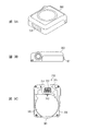
- FIG. 3 is a diagram illustrating a configuration of the terminal 300, FIG. 3A is a perspective view, FIG. 3B is a side view, and FIG. 3C is a bottom view.
- the terminal 300 has a built-in coin battery and memory.
- the terminal 300 starts an electrocardiogram measurement / recording operation and records an electrocardiogram based on an electrocardiogram signal from the sensor sheet 100. Since this measurement / recording operation is a known technique, a description thereof is omitted here.
- an attachment portion 310 that is detachably attached to a connector 140 provided on the sensor sheet 100 is provided on the back surface of the terminal 300.
- FIG. 4 is a cross-sectional view for explaining the attachment structure of the terminal 300 for attachment to the sensor sheet 100.
- FIG. 4A is a cross-sectional view before mounting
- FIG. 4B is a cross-sectional view after mounting.
- FIG. 5 is a perspective view for explaining an attachment structure of the terminal 300 for attachment to the sensor sheet 100
- FIG. 5A is a perspective view before attachment
- FIG. 5B is a perspective view after attachment.
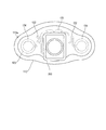
- the connector 140 provided on the sensor sheet 100 side has an oval packing 141 in plan view.
- the end of the wiring 132 whose other end is connected to the electrode 133 is arranged.
- an insertion port 311 having a size that allows the packing 141 to enter is formed on the back surface of the terminal 300.
- a spring probe 312 and a USB terminal 313 are disposed in the insertion port 311.
- a shield frame 315 is formed on the back surface of the terminal 300, and an insertion port 311 is formed by the shield frame 315.
- the shield frame 315 is provided with an external terminal (USB terminal 313) for connecting to an external device in addition to a terminal (spring probe 312) connected to the sensor (electrode 133) of the sensor sheet 100. Yes.
- This external terminal outputs biometric information stored in the memory to an external device, or sets a terminal from the external device.
- a USB terminal 313 is also provided in the insertion port 311. Therefore, when the terminal 300 is attached to the sensor sheet 100 and an electrocardiogram is measured, the USB terminal 313 is used. The terminal 313 becomes unavailable. Thereby, it is possible to reliably eliminate the possibility of electric shock due to an external electronic device being connected to the USB terminal 313 during measurement of the electrocardiogram. That is, in the present embodiment, the electrocardiogram measurement terminal (spring probe 312) and the USB terminal 313 are not physically connected at the same time, thereby ensuring safety. Furthermore, since the ECG measurement terminal (spring probe 312) and the USB terminal 313 are accommodated in the packing 141, waterproofing of these terminals is realized at the same time. That is, both waterproofness and safety are ensured with a simple configuration.
- a wide portion 150 is formed at the tip of the tongue piece 131.
- a locking notch 314 is formed on the back surface of the terminal 300.
- a hook-and-loop fastener 160 is fixed to the surface side of the upper sheet 120.
- the hook-and-loop fastener 160 can be attached to the hook-and-loop fastener 320 provided on the back side of the terminal 300.
- the terminal 300 is held on the sensor sheet 100 by the engagement between the tongue piece 131 and the locking notch 314 and the joining between the hook-and-loop fasteners 160 and 320. Is done.
- the hook-and-loop fasteners 160 and 320 have a weak surface holding force in the vertical direction but a strong surface holding force. Therefore, the tongue piece 131 and the hook-and-loop fasteners 160 and 320 reliably prevent the terminal 300 from dropping in the surface direction.
- the terminal 300 is in a state of hanging around the tongue piece 131 by engaging with the tongue piece 131 at the upper part. In this state, the hook-and-loop fasteners 160 and 320 are joined to each other and the swaying is suppressed only by lightly pressing the terminal 300 against the sensor sheet 100 side (that is, the subject side). In practice, the terminal 300 is held in a state where at least a part is lifted from the sensor sheet 100 by the tongue 131.
- the subject feels the terminal 300 with the skin at the joint portion between the tongue piece 131 and the packing 141 and the joint portion between the hook-and-loop fasteners 160 and 320. As a result, for example, the entire back surface of the terminal 300 is detected by the sensor sheet 100. Compared with the case where the terminal 300 is fixed, the uncomfortable feeling of the subject due to the presence of the terminal 300 can be reduced. If the area of the hook-and-loop fasteners 160 and 320 is reduced, the sense of discomfort of the subject can be further reduced.
- the hook-and-loop fastener 160 is disposed at a position corresponding to the gel 134. Thereby, since a gel becomes a buffer material, it becomes difficult for a subject to feel existence of terminal 300 more.
- hook-and-loop fasteners 160 and 320 instead of the hook-and-loop fasteners 160 and 320, for example, a snap button or a magnet may be used. In short, various rejoinable connectors can be used.
- the terminal connected to the sensor (electrode 133) of the sensor sheet 100 in the shield frame 315 that is shielded from the outside when attached to the sensor sheet 100 By providing an external terminal (USB terminal 313) for connecting to an external device in addition to the (spring probe 312), current from the external device is measured via the terminal 300 and the sensor sheet 100 when measuring biological information. It is possible to reliably prevent the flow to the examiner with a simple configuration.
- an electronic device other than a medical device can be connected as an external device. Since such electronic devices other than medical devices do not consider medical safety standards, there is a risk that dangerous current will flow to the subject when connected to the sensor sheet via an external terminal.
- the configuration of the present embodiment even when a general-purpose external terminal to which an electronic device other than a medical device can be connected is provided, the electronic device cannot be connected to the external terminal during measurement. Therefore, the safety of the subject can be ensured.
- the sensor sheet according to the present invention has been described with respect to a form in which all the electrodes 133 are accommodated in one sheet 110, 120.
- each electrode 133 is arranged on an independent sheet, and the subject is examined. You may apply to the sheet
- the electrode 133, the wiring 132, and the tongue piece 131 are configured integrally, they are configured separately and compared with a configuration in which they are connected via a cable or a connecting portion. , Can obtain a signal with less noise.
- the sensor mounted on the sensor sheet of the present invention is not limited to the electric circuit unit 130. Absent.
- an optical component for measuring SpO 2 may be mounted as a sensor. The sensor mounted on the sensor sheet can be selected according to the object to be measured.
- the electric circuit unit 130 as a sensor is disposed between the lower sheet 110 and the upper sheet 120 has been described, but the sensor may be disposed on the upper sheet 120.
- the central region of the sensor sheet 100 has a multilayer structure of the lower sheet 110 and the upper sheet 120 has been described.
- the upper sheet 120 does not exist in the central region. Only a single layer structure may be used. Even if it does in this way, if the intensity
- the tongue piece 131 is formed separately from the upper sheet 120 .
- the tongue piece 131 may be formed integrally with the upper sheet 120. That is, the tongue piece 131 only needs to extend from the upper sheet 120.
- the present invention can be applied to a biological information measuring apparatus that measures biological information using a sensor sheet attached to the skin of a subject and a terminal attached to the sensor sheet.
Landscapes
- Health & Medical Sciences (AREA)
- Life Sciences & Earth Sciences (AREA)
- Heart & Thoracic Surgery (AREA)
- Surgery (AREA)
- Biophysics (AREA)
- Pathology (AREA)
- Engineering & Computer Science (AREA)
- Biomedical Technology (AREA)
- Veterinary Medicine (AREA)
- Medical Informatics (AREA)
- Molecular Biology (AREA)
- Physics & Mathematics (AREA)
- Animal Behavior & Ethology (AREA)
- General Health & Medical Sciences (AREA)
- Public Health (AREA)
- Cardiology (AREA)
- Measurement And Recording Of Electrical Phenomena And Electrical Characteristics Of The Living Body (AREA)
- Chemical & Material Sciences (AREA)
- Dispersion Chemistry (AREA)
Abstract
Description
被検者の皮膚に貼着されるセンサーシートと、
前記センサーシートに取り付けられる端末と、
を有する生体情報測定装置であって、
前記端末は、
前記センサーシートに取り付けられたときに内部が外部と遮蔽されるシールドフレームを有し、
前記シールドフレーム内には、前記センサーシートのセンサーに接続されるセンサー接続端子に加えて、外部機器に接続される外部端子が設けられている。
図1は、本発明の実施の形態に係るセンサーシートの全体構成を示す分解斜視図である。図2は、センサーシートに端末を取り付けた状態を示す上面図である。センサーシートは、心電図を取得するために、被検者の胸部に貼着されて用いられる。
図3は端末300の構成を示す図であり、図3Aは斜視図、図3Bは側面図、図3Cは下面図である。
以上説明したように、本実施の形態によれば、センサーシート100に取り付けられたときに内部が外部と遮蔽されるシールドフレーム315内に、センサーシート100のセンサー(電極133)に接続される端子(スプリングプローブ312)に加えて、外部機器に接続するための外部端子(USB端子313)を設けたことにより、生体情報の測定時に外部機器からの電流が端末300及びセンサーシート100を介して被検者に流れることを、簡易な構成により確実に防止できるようになる。
110 下シート
110a 周縁部
120 上シート
130 電気回路部
131 舌片
132 配線
133 電極
134 ゲル
140 コネクタ
141 パッキン
150 幅広部
160、320 面ファスナー
210 ライナー
220 トップセパレーター
300 端末
310 取付部
311 挿入口
312 スプリングプローブ
313 USB端子
314 係止用切欠
315 シールドフレーム
Claims (4)
- 被検者の皮膚に貼着されるセンサーシートと、
前記センサーシートに取り付けられる端末と、
を有する生体情報測定装置であって、
前記端末は、
前記センサーシートに取り付けられたときに内部が外部と遮蔽されるシールドフレームを有し、
前記シールドフレーム内には、前記センサーシートのセンサーに接続されるセンサー接続端子に加えて、外部機器に接続される外部端子が設けられている、
生体情報測定装置。 - 前記センサーシートに前記端末が取り付けられた状態において、
前記センサー接続端子は、前記センサーに接続され、
前記外部端子は、前記外部機器と接続できない状態とされる、
請求項1に記載の生体情報測定装置。 - 前記センサーシートは、前記端末の前記シールドフレームに挿入されるパッキンを有し、
前記センサーシートに前記端末が取り付けられた状態において、前記シールドフレームに前記パッキンが挿入された状態となる、
請求項1又は請求項2に記載の生体情報測定装置。 - 前記パッキン内には、前記センサーシートの端子が配設されている、
請求項3に記載の生体情報測定装置。
Priority Applications (6)
| Application Number | Priority Date | Filing Date | Title |
|---|---|---|---|
| US15/759,233 US11123001B2 (en) | 2015-09-11 | 2016-09-08 | Biological information measurement device |
| CN201680051812.6A CN107949323B (zh) | 2015-09-11 | 2016-09-08 | 生物信息测定装置 |
| EP16844458.6A EP3348189B1 (en) | 2015-09-11 | 2016-09-08 | Biological information measurement device |
| KR1020207017680A KR20200074285A (ko) | 2015-09-11 | 2016-09-08 | 생체 정보 측정 장치 |
| KR1020187006944A KR102287701B1 (ko) | 2015-09-11 | 2016-09-08 | 생체 정보 측정 장치 |
| JP2017538517A JP6768673B2 (ja) | 2015-09-11 | 2016-09-08 | 生体情報測定装置 |
Applications Claiming Priority (2)
| Application Number | Priority Date | Filing Date | Title |
|---|---|---|---|
| JP2015-179597 | 2015-09-11 | ||
| JP2015179597 | 2015-09-11 |
Publications (1)
| Publication Number | Publication Date |
|---|---|
| WO2017043597A1 true WO2017043597A1 (ja) | 2017-03-16 |
Family
ID=58239848
Family Applications (1)
| Application Number | Title | Priority Date | Filing Date |
|---|---|---|---|
| PCT/JP2016/076506 Ceased WO2017043597A1 (ja) | 2015-09-11 | 2016-09-08 | 生体情報測定装置 |
Country Status (6)
| Country | Link |
|---|---|
| US (1) | US11123001B2 (ja) |
| EP (1) | EP3348189B1 (ja) |
| JP (1) | JP6768673B2 (ja) |
| KR (2) | KR20200074285A (ja) |
| CN (1) | CN107949323B (ja) |
| WO (1) | WO2017043597A1 (ja) |
Cited By (7)
| Publication number | Priority date | Publication date | Assignee | Title |
|---|---|---|---|---|
| JP2021525616A (ja) * | 2018-06-07 | 2021-09-27 | コーニンクレッカ フィリップス エヌ ヴェKoninklijke Philips N.V. | ウェアラブルデバイス |
| US12213791B2 (en) | 2020-08-06 | 2025-02-04 | Irhythm Technologies, Inc. | Wearable device |
| US12245859B2 (en) | 2013-01-24 | 2025-03-11 | Irhythm Technologies, Inc. | Physiological monitoring device |
| US12274554B2 (en) | 2010-05-12 | 2025-04-15 | Irhythm Technologies, Inc. | Device features and design elements for long-term adhesion |
| USD1083114S1 (en) | 2021-08-06 | 2025-07-08 | Irhythm Technologies, Inc. | Physiological monitoring device |
| US12507931B2 (en) | 2020-08-06 | 2025-12-30 | Irhythm Technologies, Inc. | Wearable device with conductive traces and insulator |
| US12603173B2 (en) | 2014-10-31 | 2026-04-14 | Irhythm Technologies, Inc. | Wearable monitor |
Families Citing this family (5)
| Publication number | Priority date | Publication date | Assignee | Title |
|---|---|---|---|---|
| JP7335228B2 (ja) * | 2018-03-28 | 2023-08-29 | ニプロ株式会社 | 生体用電極パッドと生体信号処理装置との組合せ |
| TWM569612U (zh) * | 2018-08-28 | 2018-11-11 | 廣達電腦股份有限公司 | 心電圖裝置 |
| CN111184507B (zh) * | 2019-03-12 | 2024-04-26 | 深圳碳云智能数字生命健康管理有限公司 | 微型心电采集设备、采集器及主机 |
| WO2020262403A1 (ja) * | 2019-06-27 | 2020-12-30 | ニプロ株式会社 | 生体用電極パッド付き収納ケースおよび生体用電極パッド付き収納ケースを備えた生体信号処理装置 |
| JP7767288B2 (ja) | 2019-12-23 | 2025-11-11 | アリメトリー リミテッド | 電極パッチおよび接続システム |
Citations (2)
| Publication number | Priority date | Publication date | Assignee | Title |
|---|---|---|---|---|
| JP2009517160A (ja) * | 2005-11-30 | 2009-04-30 | コーニンクレッカ フィリップス エレクトロニクス エヌ ヴィ | 薄型の医療監視パッチに対する電気機械コネクタ |
| JP2011516110A (ja) * | 2008-03-10 | 2011-05-26 | コーニンクレッカ フィリップス エレクトロニクス エヌ ヴィ | 連続的な外来患者のecg監視システム |
Family Cites Families (11)
| Publication number | Priority date | Publication date | Assignee | Title |
|---|---|---|---|---|
| JP2631261B2 (ja) | 1993-02-23 | 1997-07-16 | 務 大竹 | 生体電気信号記録具 |
| JP3697628B2 (ja) * | 1999-09-09 | 2005-09-21 | 日本光電工業株式会社 | 生体信号検出装置およびホルタ心電計 |
| JP2001004622A (ja) * | 2000-01-01 | 2001-01-12 | Toto Ltd | 健康管理装置 |
| JP2001269322A (ja) | 2000-03-24 | 2001-10-02 | Hiroshi Matsumoto | 心電図信号誘導用電極装置及び心電図信号測定装置 |
| EP1979040B1 (en) * | 2006-01-23 | 2009-09-02 | Koninklijke Philips Electronics N.V. | Improved biomedical electrode for extended patient wear featuring a tap, or snap, which is isolated from the retention seal |
| WO2009112975A1 (en) * | 2008-03-10 | 2009-09-17 | Koninklijke Philips Electronics N.V. | Watertight cardiac monitoring system |
| JP5612566B2 (ja) * | 2008-05-01 | 2014-10-22 | スリーエム イノベイティブ プロパティズ カンパニー | 医用センサシステム |
| WO2014057083A2 (en) * | 2012-10-12 | 2014-04-17 | Delta, Dansk Elektronik, Lys Og Akustik | A monitoring device |
| US10022053B2 (en) * | 2013-02-22 | 2018-07-17 | Cloud Dx, Inc. | Simultaneous multi-parameter physiological monitoring device with local and remote analytical capability |
| WO2015048191A1 (en) * | 2013-09-25 | 2015-04-02 | Bardy Diagnostics, Inc. | Event alerting through actigraphy embedded within electrocardiographic data |
| US9775536B2 (en) * | 2013-09-25 | 2017-10-03 | Bardy Diagnostics, Inc. | Method for constructing a stress-pliant physiological electrode assembly |
-
2016
- 2016-09-08 KR KR1020207017680A patent/KR20200074285A/ko not_active Withdrawn
- 2016-09-08 EP EP16844458.6A patent/EP3348189B1/en active Active
- 2016-09-08 CN CN201680051812.6A patent/CN107949323B/zh active Active
- 2016-09-08 US US15/759,233 patent/US11123001B2/en active Active
- 2016-09-08 KR KR1020187006944A patent/KR102287701B1/ko active Active
- 2016-09-08 JP JP2017538517A patent/JP6768673B2/ja active Active
- 2016-09-08 WO PCT/JP2016/076506 patent/WO2017043597A1/ja not_active Ceased
Patent Citations (2)
| Publication number | Priority date | Publication date | Assignee | Title |
|---|---|---|---|---|
| JP2009517160A (ja) * | 2005-11-30 | 2009-04-30 | コーニンクレッカ フィリップス エレクトロニクス エヌ ヴィ | 薄型の医療監視パッチに対する電気機械コネクタ |
| JP2011516110A (ja) * | 2008-03-10 | 2011-05-26 | コーニンクレッカ フィリップス エレクトロニクス エヌ ヴィ | 連続的な外来患者のecg監視システム |
Cited By (16)
| Publication number | Priority date | Publication date | Assignee | Title |
|---|---|---|---|---|
| US12408856B1 (en) | 2010-05-12 | 2025-09-09 | Irhythm Technologies, Inc. | Device features and design elements for long-term adhesion |
| US12274554B2 (en) | 2010-05-12 | 2025-04-15 | Irhythm Technologies, Inc. | Device features and design elements for long-term adhesion |
| US12303277B2 (en) | 2010-05-12 | 2025-05-20 | Irhythm Technologies, Inc. | Device features and design elements for long-term adhesion |
| US12324668B2 (en) | 2010-05-12 | 2025-06-10 | Irhythm Technologies, Inc. | Device features and design elements for long-term adhesion |
| US12357212B2 (en) | 2013-01-24 | 2025-07-15 | Irhythm Technologies, Inc. | Physiological monitoring device |
| US12245860B2 (en) | 2013-01-24 | 2025-03-11 | Irhythm Technologies, Inc. | Physiological monitoring device |
| US12245859B2 (en) | 2013-01-24 | 2025-03-11 | Irhythm Technologies, Inc. | Physiological monitoring device |
| US12303275B2 (en) | 2013-01-24 | 2025-05-20 | Irhythm Technologies, Inc. | Physiological monitoring device |
| US12402819B1 (en) | 2013-01-24 | 2025-09-02 | Irhythm Technologies, Inc. | Physiological monitoring device |
| US12603173B2 (en) | 2014-10-31 | 2026-04-14 | Irhythm Technologies, Inc. | Wearable monitor |
| JP7285859B2 (ja) | 2018-06-07 | 2023-06-02 | コーニンクレッカ フィリップス エヌ ヴェ | ウェアラブルデバイス |
| JP2021525616A (ja) * | 2018-06-07 | 2021-09-27 | コーニンクレッカ フィリップス エヌ ヴェKoninklijke Philips N.V. | ウェアラブルデバイス |
| US12213791B2 (en) | 2020-08-06 | 2025-02-04 | Irhythm Technologies, Inc. | Wearable device |
| US12507931B2 (en) | 2020-08-06 | 2025-12-30 | Irhythm Technologies, Inc. | Wearable device with conductive traces and insulator |
| US12582339B2 (en) | 2020-08-06 | 2026-03-24 | Irhythm Technologies, Inc. | Electrical components for physiological monitoring device |
| USD1083114S1 (en) | 2021-08-06 | 2025-07-08 | Irhythm Technologies, Inc. | Physiological monitoring device |
Also Published As
| Publication number | Publication date |
|---|---|
| CN107949323B (zh) | 2021-10-12 |
| JPWO2017043597A1 (ja) | 2018-04-26 |
| EP3348189A4 (en) | 2019-03-13 |
| KR20180039698A (ko) | 2018-04-18 |
| KR20200074285A (ko) | 2020-06-24 |
| US11123001B2 (en) | 2021-09-21 |
| CN107949323A (zh) | 2018-04-20 |
| JP6768673B2 (ja) | 2020-10-14 |
| EP3348189B1 (en) | 2022-09-07 |
| KR102287701B1 (ko) | 2021-08-09 |
| US20180235501A1 (en) | 2018-08-23 |
| EP3348189A1 (en) | 2018-07-18 |
Similar Documents
| Publication | Publication Date | Title |
|---|---|---|
| JP6507254B2 (ja) | 生体情報測定装置 | |
| WO2017043597A1 (ja) | 生体情報測定装置 | |
| JP6537618B2 (ja) | センサーシート | |
| EP4137050A1 (en) | Bioelectrode that can be worn for a long period of time | |
| JP2015534495A (ja) | 監視デバイス | |
| US11615885B2 (en) | Wearable sensing device and sensor unit for acquiring one or more physiological signals of a subject | |
| JP6454993B2 (ja) | 生体情報収集装置と生体情報収集装置用粘着部材 | |
| WO2018196445A1 (zh) | 连接组件及智能服装 | |
| US20140378848A1 (en) | Method and Apparatus for Motion Artifact Reduction in ECG Harness | |
| US20110213258A1 (en) | Strap based reliable heart rate or electro cardiogram monitor with wireless data transmission | |
| JP5952170B2 (ja) | 防水性生体電極 | |
| JP6158263B2 (ja) | 防水性生体電極 |
Legal Events
| Date | Code | Title | Description |
|---|---|---|---|
| 121 | Ep: the epo has been informed by wipo that ep was designated in this application |
Ref document number: 16844458 Country of ref document: EP Kind code of ref document: A1 |
|
| ENP | Entry into the national phase |
Ref document number: 2017538517 Country of ref document: JP Kind code of ref document: A |
|
| ENP | Entry into the national phase |
Ref document number: 20187006944 Country of ref document: KR Kind code of ref document: A |
|
| WWE | Wipo information: entry into national phase |
Ref document number: 15759233 Country of ref document: US |
|
| NENP | Non-entry into the national phase |
Ref country code: DE |
|
| WWE | Wipo information: entry into national phase |
Ref document number: 2016844458 Country of ref document: EP |