WO2017047352A1 - 作業機械の油圧駆動装置 - Google Patents
作業機械の油圧駆動装置 Download PDFInfo
- Publication number
- WO2017047352A1 WO2017047352A1 PCT/JP2016/074909 JP2016074909W WO2017047352A1 WO 2017047352 A1 WO2017047352 A1 WO 2017047352A1 JP 2016074909 W JP2016074909 W JP 2016074909W WO 2017047352 A1 WO2017047352 A1 WO 2017047352A1
- Authority
- WO
- WIPO (PCT)
- Prior art keywords
- pump motor
- accumulator
- pump
- hydraulic
- line
- Prior art date
- Legal status (The legal status is an assumption and is not a legal conclusion. Google has not performed a legal analysis and makes no representation as to the accuracy of the status listed.)
- Ceased
Links
Images




Classifications
-
- E—FIXED CONSTRUCTIONS
- E02—HYDRAULIC ENGINEERING; FOUNDATIONS; SOIL SHIFTING
- E02F—DREDGING; SOIL-SHIFTING
- E02F9/00—Component parts of dredgers or soil-shifting machines, not restricted to one of the kinds covered by groups E02F3/00 - E02F7/00
- E02F9/20—Drives; Control devices
- E02F9/22—Hydraulic or pneumatic drives
- E02F9/2217—Hydraulic or pneumatic drives with energy recovery arrangements, e.g. using accumulators, flywheels
-
- B—PERFORMING OPERATIONS; TRANSPORTING
- B66—HOISTING; LIFTING; HAULING
- B66C—CRANES; LOAD-ENGAGING ELEMENTS OR DEVICES FOR CRANES, CAPSTANS, WINCHES, OR TACKLES
- B66C13/00—Other constructional features or details
- B66C13/18—Control systems or devices
- B66C13/20—Control systems or devices for non-electric drives
-
- B—PERFORMING OPERATIONS; TRANSPORTING
- B66—HOISTING; LIFTING; HAULING
- B66D—CAPSTANS; WINCHES; TACKLES, e.g. PULLEY BLOCKS; HOISTS
- B66D1/00—Rope, cable, or chain winding mechanisms; Capstans
- B66D1/28—Other constructional details
- B66D1/40—Control devices
- B66D1/42—Control devices non-automatic
- B66D1/44—Control devices non-automatic pneumatic of hydraulic
-
- E—FIXED CONSTRUCTIONS
- E02—HYDRAULIC ENGINEERING; FOUNDATIONS; SOIL SHIFTING
- E02F—DREDGING; SOIL-SHIFTING
- E02F9/00—Component parts of dredgers or soil-shifting machines, not restricted to one of the kinds covered by groups E02F3/00 - E02F7/00
- E02F9/20—Drives; Control devices
- E02F9/2016—Winches
-
- E—FIXED CONSTRUCTIONS
- E02—HYDRAULIC ENGINEERING; FOUNDATIONS; SOIL SHIFTING
- E02F—DREDGING; SOIL-SHIFTING
- E02F9/00—Component parts of dredgers or soil-shifting machines, not restricted to one of the kinds covered by groups E02F3/00 - E02F7/00
- E02F9/20—Drives; Control devices
- E02F9/22—Hydraulic or pneumatic drives
- E02F9/2221—Control of flow rate; Load sensing arrangements
- E02F9/2239—Control of flow rate; Load sensing arrangements using two or more pumps with cross-assistance
-
- E—FIXED CONSTRUCTIONS
- E02—HYDRAULIC ENGINEERING; FOUNDATIONS; SOIL SHIFTING
- E02F—DREDGING; SOIL-SHIFTING
- E02F9/00—Component parts of dredgers or soil-shifting machines, not restricted to one of the kinds covered by groups E02F3/00 - E02F7/00
- E02F9/20—Drives; Control devices
- E02F9/22—Hydraulic or pneumatic drives
- E02F9/2246—Control of prime movers, e.g. depending on the hydraulic load of work tools
-
- E—FIXED CONSTRUCTIONS
- E02—HYDRAULIC ENGINEERING; FOUNDATIONS; SOIL SHIFTING
- E02F—DREDGING; SOIL-SHIFTING
- E02F9/00—Component parts of dredgers or soil-shifting machines, not restricted to one of the kinds covered by groups E02F3/00 - E02F7/00
- E02F9/20—Drives; Control devices
- E02F9/22—Hydraulic or pneumatic drives
- E02F9/2278—Hydraulic circuits
- E02F9/2292—Systems with two or more pumps
-
- E—FIXED CONSTRUCTIONS
- E02—HYDRAULIC ENGINEERING; FOUNDATIONS; SOIL SHIFTING
- E02F—DREDGING; SOIL-SHIFTING
- E02F9/00—Component parts of dredgers or soil-shifting machines, not restricted to one of the kinds covered by groups E02F3/00 - E02F7/00
- E02F9/20—Drives; Control devices
- E02F9/22—Hydraulic or pneumatic drives
- E02F9/2278—Hydraulic circuits
- E02F9/2296—Systems with a variable displacement pump
-
- F—MECHANICAL ENGINEERING; LIGHTING; HEATING; WEAPONS; BLASTING
- F15—FLUID-PRESSURE ACTUATORS; HYDRAULICS OR PNEUMATICS IN GENERAL
- F15B—SYSTEMS ACTING BY MEANS OF FLUIDS IN GENERAL; FLUID-PRESSURE ACTUATORS, e.g. SERVOMOTORS; DETAILS OF FLUID-PRESSURE SYSTEMS, NOT OTHERWISE PROVIDED FOR
- F15B1/00—Installations or systems with accumulators; Supply reservoir or sump assemblies
- F15B1/02—Installations or systems with accumulators
- F15B1/024—Installations or systems with accumulators used as a supplementary power source, e.g. to store energy in idle periods to balance pump load
-
- F—MECHANICAL ENGINEERING; LIGHTING; HEATING; WEAPONS; BLASTING
- F15—FLUID-PRESSURE ACTUATORS; HYDRAULICS OR PNEUMATICS IN GENERAL
- F15B—SYSTEMS ACTING BY MEANS OF FLUIDS IN GENERAL; FLUID-PRESSURE ACTUATORS, e.g. SERVOMOTORS; DETAILS OF FLUID-PRESSURE SYSTEMS, NOT OTHERWISE PROVIDED FOR
- F15B11/00—Servomotor systems without provision for follow-up action; Circuits therefor
- F15B11/16—Servomotor systems without provision for follow-up action; Circuits therefor with two or more servomotors
- F15B11/17—Servomotor systems without provision for follow-up action; Circuits therefor with two or more servomotors using two or more pumps
-
- F—MECHANICAL ENGINEERING; LIGHTING; HEATING; WEAPONS; BLASTING
- F15—FLUID-PRESSURE ACTUATORS; HYDRAULICS OR PNEUMATICS IN GENERAL
- F15B—SYSTEMS ACTING BY MEANS OF FLUIDS IN GENERAL; FLUID-PRESSURE ACTUATORS, e.g. SERVOMOTORS; DETAILS OF FLUID-PRESSURE SYSTEMS, NOT OTHERWISE PROVIDED FOR
- F15B21/00—Common features of fluid actuator systems; Fluid-pressure actuator systems or details thereof, not covered by any other group of this subclass
- F15B21/14—Energy-recuperation means
-
- F—MECHANICAL ENGINEERING; LIGHTING; HEATING; WEAPONS; BLASTING
- F15—FLUID-PRESSURE ACTUATORS; HYDRAULICS OR PNEUMATICS IN GENERAL
- F15B—SYSTEMS ACTING BY MEANS OF FLUIDS IN GENERAL; FLUID-PRESSURE ACTUATORS, e.g. SERVOMOTORS; DETAILS OF FLUID-PRESSURE SYSTEMS, NOT OTHERWISE PROVIDED FOR
- F15B2201/00—Accumulators
- F15B2201/50—Monitoring, detection and testing means for accumulators
- F15B2201/51—Pressure detection
-
- F—MECHANICAL ENGINEERING; LIGHTING; HEATING; WEAPONS; BLASTING
- F15—FLUID-PRESSURE ACTUATORS; HYDRAULICS OR PNEUMATICS IN GENERAL
- F15B—SYSTEMS ACTING BY MEANS OF FLUIDS IN GENERAL; FLUID-PRESSURE ACTUATORS, e.g. SERVOMOTORS; DETAILS OF FLUID-PRESSURE SYSTEMS, NOT OTHERWISE PROVIDED FOR
- F15B2211/00—Circuits for servomotor systems
- F15B2211/20—Fluid pressure source, e.g. accumulator or variable axial piston pump
- F15B2211/205—Systems with pumps
- F15B2211/2053—Type of pump
- F15B2211/20546—Type of pump variable capacity
-
- F—MECHANICAL ENGINEERING; LIGHTING; HEATING; WEAPONS; BLASTING
- F15—FLUID-PRESSURE ACTUATORS; HYDRAULICS OR PNEUMATICS IN GENERAL
- F15B—SYSTEMS ACTING BY MEANS OF FLUIDS IN GENERAL; FLUID-PRESSURE ACTUATORS, e.g. SERVOMOTORS; DETAILS OF FLUID-PRESSURE SYSTEMS, NOT OTHERWISE PROVIDED FOR
- F15B2211/00—Circuits for servomotor systems
- F15B2211/20—Fluid pressure source, e.g. accumulator or variable axial piston pump
- F15B2211/205—Systems with pumps
- F15B2211/2053—Type of pump
- F15B2211/20569—Type of pump capable of working as pump and motor
-
- F—MECHANICAL ENGINEERING; LIGHTING; HEATING; WEAPONS; BLASTING
- F15—FLUID-PRESSURE ACTUATORS; HYDRAULICS OR PNEUMATICS IN GENERAL
- F15B—SYSTEMS ACTING BY MEANS OF FLUIDS IN GENERAL; FLUID-PRESSURE ACTUATORS, e.g. SERVOMOTORS; DETAILS OF FLUID-PRESSURE SYSTEMS, NOT OTHERWISE PROVIDED FOR
- F15B2211/00—Circuits for servomotor systems
- F15B2211/20—Fluid pressure source, e.g. accumulator or variable axial piston pump
- F15B2211/205—Systems with pumps
- F15B2211/20576—Systems with pumps with multiple pumps
-
- F—MECHANICAL ENGINEERING; LIGHTING; HEATING; WEAPONS; BLASTING
- F15—FLUID-PRESSURE ACTUATORS; HYDRAULICS OR PNEUMATICS IN GENERAL
- F15B—SYSTEMS ACTING BY MEANS OF FLUIDS IN GENERAL; FLUID-PRESSURE ACTUATORS, e.g. SERVOMOTORS; DETAILS OF FLUID-PRESSURE SYSTEMS, NOT OTHERWISE PROVIDED FOR
- F15B2211/00—Circuits for servomotor systems
- F15B2211/20—Fluid pressure source, e.g. accumulator or variable axial piston pump
- F15B2211/21—Systems with pressure sources other than pumps, e.g. with a pyrotechnical charge
- F15B2211/212—Systems with pressure sources other than pumps, e.g. with a pyrotechnical charge the pressure sources being accumulators
-
- F—MECHANICAL ENGINEERING; LIGHTING; HEATING; WEAPONS; BLASTING
- F15—FLUID-PRESSURE ACTUATORS; HYDRAULICS OR PNEUMATICS IN GENERAL
- F15B—SYSTEMS ACTING BY MEANS OF FLUIDS IN GENERAL; FLUID-PRESSURE ACTUATORS, e.g. SERVOMOTORS; DETAILS OF FLUID-PRESSURE SYSTEMS, NOT OTHERWISE PROVIDED FOR
- F15B2211/00—Circuits for servomotor systems
- F15B2211/30—Directional control
- F15B2211/305—Directional control characterised by the type of valves
- F15B2211/30505—Non-return valves, i.e. check valves
-
- F—MECHANICAL ENGINEERING; LIGHTING; HEATING; WEAPONS; BLASTING
- F15—FLUID-PRESSURE ACTUATORS; HYDRAULICS OR PNEUMATICS IN GENERAL
- F15B—SYSTEMS ACTING BY MEANS OF FLUIDS IN GENERAL; FLUID-PRESSURE ACTUATORS, e.g. SERVOMOTORS; DETAILS OF FLUID-PRESSURE SYSTEMS, NOT OTHERWISE PROVIDED FOR
- F15B2211/00—Circuits for servomotor systems
- F15B2211/30—Directional control
- F15B2211/305—Directional control characterised by the type of valves
- F15B2211/3056—Assemblies of multiple valves
- F15B2211/30565—Assemblies of multiple valves having multiple valves for a single output member, e.g. for creating higher valve function by use of multiple valves like two 2/2-valves replacing a 5/3-valve
-
- F—MECHANICAL ENGINEERING; LIGHTING; HEATING; WEAPONS; BLASTING
- F15—FLUID-PRESSURE ACTUATORS; HYDRAULICS OR PNEUMATICS IN GENERAL
- F15B—SYSTEMS ACTING BY MEANS OF FLUIDS IN GENERAL; FLUID-PRESSURE ACTUATORS, e.g. SERVOMOTORS; DETAILS OF FLUID-PRESSURE SYSTEMS, NOT OTHERWISE PROVIDED FOR
- F15B2211/00—Circuits for servomotor systems
- F15B2211/30—Directional control
- F15B2211/305—Directional control characterised by the type of valves
- F15B2211/3056—Assemblies of multiple valves
- F15B2211/30565—Assemblies of multiple valves having multiple valves for a single output member, e.g. for creating higher valve function by use of multiple valves like two 2/2-valves replacing a 5/3-valve
- F15B2211/3057—Assemblies of multiple valves having multiple valves for a single output member, e.g. for creating higher valve function by use of multiple valves like two 2/2-valves replacing a 5/3-valve having two valves, one for each port of a double-acting output member
-
- F—MECHANICAL ENGINEERING; LIGHTING; HEATING; WEAPONS; BLASTING
- F15—FLUID-PRESSURE ACTUATORS; HYDRAULICS OR PNEUMATICS IN GENERAL
- F15B—SYSTEMS ACTING BY MEANS OF FLUIDS IN GENERAL; FLUID-PRESSURE ACTUATORS, e.g. SERVOMOTORS; DETAILS OF FLUID-PRESSURE SYSTEMS, NOT OTHERWISE PROVIDED FOR
- F15B2211/00—Circuits for servomotor systems
- F15B2211/30—Directional control
- F15B2211/305—Directional control characterised by the type of valves
- F15B2211/3056—Assemblies of multiple valves
- F15B2211/30565—Assemblies of multiple valves having multiple valves for a single output member, e.g. for creating higher valve function by use of multiple valves like two 2/2-valves replacing a 5/3-valve
- F15B2211/3058—Assemblies of multiple valves having multiple valves for a single output member, e.g. for creating higher valve function by use of multiple valves like two 2/2-valves replacing a 5/3-valve having additional valves for interconnecting the fluid chambers of a double-acting actuator, e.g. for regeneration mode or for floating mode
-
- F—MECHANICAL ENGINEERING; LIGHTING; HEATING; WEAPONS; BLASTING
- F15—FLUID-PRESSURE ACTUATORS; HYDRAULICS OR PNEUMATICS IN GENERAL
- F15B—SYSTEMS ACTING BY MEANS OF FLUIDS IN GENERAL; FLUID-PRESSURE ACTUATORS, e.g. SERVOMOTORS; DETAILS OF FLUID-PRESSURE SYSTEMS, NOT OTHERWISE PROVIDED FOR
- F15B2211/00—Circuits for servomotor systems
- F15B2211/30—Directional control
- F15B2211/315—Directional control characterised by the connections of the valve or valves in the circuit
- F15B2211/3157—Directional control characterised by the connections of the valve or valves in the circuit being connected to a pressure source, an output member and a return line
- F15B2211/31588—Directional control characterised by the connections of the valve or valves in the circuit being connected to a pressure source, an output member and a return line having a single pressure source and multiple output members
-
- F—MECHANICAL ENGINEERING; LIGHTING; HEATING; WEAPONS; BLASTING
- F15—FLUID-PRESSURE ACTUATORS; HYDRAULICS OR PNEUMATICS IN GENERAL
- F15B—SYSTEMS ACTING BY MEANS OF FLUIDS IN GENERAL; FLUID-PRESSURE ACTUATORS, e.g. SERVOMOTORS; DETAILS OF FLUID-PRESSURE SYSTEMS, NOT OTHERWISE PROVIDED FOR
- F15B2211/00—Circuits for servomotor systems
- F15B2211/60—Circuit components or control therefor
- F15B2211/61—Secondary circuits
- F15B2211/611—Diverting circuits, e.g. for cooling or filtering
-
- F—MECHANICAL ENGINEERING; LIGHTING; HEATING; WEAPONS; BLASTING
- F15—FLUID-PRESSURE ACTUATORS; HYDRAULICS OR PNEUMATICS IN GENERAL
- F15B—SYSTEMS ACTING BY MEANS OF FLUIDS IN GENERAL; FLUID-PRESSURE ACTUATORS, e.g. SERVOMOTORS; DETAILS OF FLUID-PRESSURE SYSTEMS, NOT OTHERWISE PROVIDED FOR
- F15B2211/00—Circuits for servomotor systems
- F15B2211/60—Circuit components or control therefor
- F15B2211/625—Accumulators
-
- F—MECHANICAL ENGINEERING; LIGHTING; HEATING; WEAPONS; BLASTING
- F15—FLUID-PRESSURE ACTUATORS; HYDRAULICS OR PNEUMATICS IN GENERAL
- F15B—SYSTEMS ACTING BY MEANS OF FLUIDS IN GENERAL; FLUID-PRESSURE ACTUATORS, e.g. SERVOMOTORS; DETAILS OF FLUID-PRESSURE SYSTEMS, NOT OTHERWISE PROVIDED FOR
- F15B2211/00—Circuits for servomotor systems
- F15B2211/60—Circuit components or control therefor
- F15B2211/63—Electronic controllers
- F15B2211/6303—Electronic controllers using input signals
- F15B2211/6306—Electronic controllers using input signals representing a pressure
-
- F—MECHANICAL ENGINEERING; LIGHTING; HEATING; WEAPONS; BLASTING
- F15—FLUID-PRESSURE ACTUATORS; HYDRAULICS OR PNEUMATICS IN GENERAL
- F15B—SYSTEMS ACTING BY MEANS OF FLUIDS IN GENERAL; FLUID-PRESSURE ACTUATORS, e.g. SERVOMOTORS; DETAILS OF FLUID-PRESSURE SYSTEMS, NOT OTHERWISE PROVIDED FOR
- F15B2211/00—Circuits for servomotor systems
- F15B2211/70—Output members, e.g. hydraulic motors or cylinders or control therefor
- F15B2211/705—Output members, e.g. hydraulic motors or cylinders or control therefor characterised by the type of output members or actuators
- F15B2211/7051—Linear output members
- F15B2211/7053—Double-acting output members
-
- F—MECHANICAL ENGINEERING; LIGHTING; HEATING; WEAPONS; BLASTING
- F15—FLUID-PRESSURE ACTUATORS; HYDRAULICS OR PNEUMATICS IN GENERAL
- F15B—SYSTEMS ACTING BY MEANS OF FLUIDS IN GENERAL; FLUID-PRESSURE ACTUATORS, e.g. SERVOMOTORS; DETAILS OF FLUID-PRESSURE SYSTEMS, NOT OTHERWISE PROVIDED FOR
- F15B2211/00—Circuits for servomotor systems
- F15B2211/70—Output members, e.g. hydraulic motors or cylinders or control therefor
- F15B2211/705—Output members, e.g. hydraulic motors or cylinders or control therefor characterised by the type of output members or actuators
- F15B2211/7058—Rotary output members
-
- F—MECHANICAL ENGINEERING; LIGHTING; HEATING; WEAPONS; BLASTING
- F15—FLUID-PRESSURE ACTUATORS; HYDRAULICS OR PNEUMATICS IN GENERAL
- F15B—SYSTEMS ACTING BY MEANS OF FLUIDS IN GENERAL; FLUID-PRESSURE ACTUATORS, e.g. SERVOMOTORS; DETAILS OF FLUID-PRESSURE SYSTEMS, NOT OTHERWISE PROVIDED FOR
- F15B2211/00—Circuits for servomotor systems
- F15B2211/70—Output members, e.g. hydraulic motors or cylinders or control therefor
- F15B2211/71—Multiple output members, e.g. multiple hydraulic motors or cylinders
- F15B2211/7135—Combinations of output members of different types, e.g. single-acting cylinders with rotary motors
-
- F—MECHANICAL ENGINEERING; LIGHTING; HEATING; WEAPONS; BLASTING
- F15—FLUID-PRESSURE ACTUATORS; HYDRAULICS OR PNEUMATICS IN GENERAL
- F15B—SYSTEMS ACTING BY MEANS OF FLUIDS IN GENERAL; FLUID-PRESSURE ACTUATORS, e.g. SERVOMOTORS; DETAILS OF FLUID-PRESSURE SYSTEMS, NOT OTHERWISE PROVIDED FOR
- F15B2211/00—Circuits for servomotor systems
- F15B2211/70—Output members, e.g. hydraulic motors or cylinders or control therefor
- F15B2211/76—Control of force or torque of the output member
- F15B2211/761—Control of a negative load, i.e. of a load generating hydraulic energy
-
- F—MECHANICAL ENGINEERING; LIGHTING; HEATING; WEAPONS; BLASTING
- F15—FLUID-PRESSURE ACTUATORS; HYDRAULICS OR PNEUMATICS IN GENERAL
- F15B—SYSTEMS ACTING BY MEANS OF FLUIDS IN GENERAL; FLUID-PRESSURE ACTUATORS, e.g. SERVOMOTORS; DETAILS OF FLUID-PRESSURE SYSTEMS, NOT OTHERWISE PROVIDED FOR
- F15B2211/00—Circuits for servomotor systems
- F15B2211/70—Output members, e.g. hydraulic motors or cylinders or control therefor
- F15B2211/76—Control of force or torque of the output member
- F15B2211/763—Control of torque of the output member by means of a variable capacity motor, i.e. by a secondary control on the motor
-
- F—MECHANICAL ENGINEERING; LIGHTING; HEATING; WEAPONS; BLASTING
- F15—FLUID-PRESSURE ACTUATORS; HYDRAULICS OR PNEUMATICS IN GENERAL
- F15B—SYSTEMS ACTING BY MEANS OF FLUIDS IN GENERAL; FLUID-PRESSURE ACTUATORS, e.g. SERVOMOTORS; DETAILS OF FLUID-PRESSURE SYSTEMS, NOT OTHERWISE PROVIDED FOR
- F15B2211/00—Circuits for servomotor systems
- F15B2211/80—Other types of control related to particular problems or conditions
- F15B2211/85—Control during special operating conditions
- F15B2211/853—Control during special operating conditions during stopping
Definitions
- the present invention relates to a hydraulic drive device provided in a work machine such as a hydraulic excavator.
- a hydraulic drive device provided in a work machine includes a hydraulic pump that discharges hydraulic oil, and a hydraulic actuator that operates to move a driving target in response to the supply of hydraulic oil discharged from the hydraulic pump.
- a technique using a so-called pump motor that has both a pump function and a motor function is known in order for the hydraulic actuator to regenerate energy due to an external force applied from the drive object.
- Patent Document 1 discloses an apparatus including a plurality of reversible adjustment units, each of which is a so-called pump motor.
- the apparatus is provided in a boom drive circuit including a first reversible adjustment unit E1 and a second reversible adjustment unit E2 provided in a turning drive circuit for turning the turning body, and a boom drive circuit including a boom cylinder for driving the boom.
- the first reversible adjustment unit E1 operates as a pump that discharges the hydraulic oil
- the second reversible adjustment unit E2 receives the supply of the hydraulic oil to thereby turn the turning body. Acts as a rotating motor.
- the second reversible adjustment unit E2 operates as a pump that discharges high-pressure hydraulic oil by the rotational energy of the rotary body, and the high-pressure hydraulic oil is stored in a pressure accumulator Spr provided in the turning drive circuit. It is done.
- the high-pressure oil stored in the pressure accumulator Spr is used as power for assisting the engine via the reversible adjustment unit E1 as necessary, thereby regenerating the rotational energy of the revolving structure during the revolving deceleration. .
- the energy of hydraulic oil discharged from the boom cylinder during the boom lowering operation is stored in a pressure accumulator Sph provided in the boom drive circuit via the reversible adjustment units E3 and E4, or the swing drive It is also possible to supply the accumulator Spr of the circuit.
- energy stored in the pressure accumulators Spr and Sph is converted into power through the reversible adjustment units E3, E4 and E1, and contributes to assisting the engine.
- the pump motor constituting the reversible adjustment unit has both a function as a hydraulic pump and a function as a hydraulic motor, the pump motor is more expensive than a general hydraulic pump or hydraulic motor.
- the pump motor since each of the turning drive circuit and the boom drive circuit needs to include a plurality of pump motors, the required number of pump motors is large, and the cost and installation space are remarkably increased accordingly. An increase is inevitable.
- An object of the present invention is to provide a hydraulic drive device that can drive a plurality of drive targets in a work machine and regenerate energy thereof with a simple and low-cost configuration.
- a hydraulic drive device for hydraulically driving a first drive object and a second drive object included in a work machine, and the first drive object is driven by being driven by a prime mover.
- a first pump motor that can be switched between a first pump operating state for sucking and discharging hydraulic oil for discharge from a tank and a first motor operating state for receiving power supplied to generate power, and the first drive target
- the second motor operating state that moves the first driving object in response to the supply of hydraulic oil discharged from the first pump motor in the first pump operating state and the energy of the first driving object
- a second pump motor that can be switched to a second pump operating state that operates to suck and discharge hydraulic oil from the tank by receiving supply, and from the first pump motor to the second pump.
- a first pump motor line that interconnects the first pump motor and the second pump motor so as to enable the supply of hydraulic oil to the booster motor, the first pump motor line, and the second pump motor line.
- a first accumulator for receiving and accumulating hydraulic oil discharged from the second pump motor in a pump operating state; and a pressure in the first accumulator interposed between the first accumulator and the first pump motor.
- a pressure holding valve having a function of preventing pressure release from the first accumulator to the first pump motor so as to hold the pressure, and the second drive connected to the second drive object and receiving the supply of hydraulic oil
- a regenerative hydraulic actuator that moves a target, and a hydraulic pump that sucks and discharges hydraulic fluid to be supplied to the regenerative hydraulic actuator from a tank;
- a second accumulator that receives and accumulates hydraulic fluid that is boosted by the energy of the second drive target and discharged from the regeneration target hydraulic actuator, and the pressure of the hydraulic fluid stored in the second accumulator is the first motor.
- a second pump motor line connecting the second accumulator to the first pump motor so as to be released to the first pump motor in operation and to drive the first pump motor;
- the pump motor line is opened and switched between an open state in which pressure can be released from the second accumulator to the first pump motor and a closed state in which the second pump motor line is shut off to prevent the pressure release.
- a pressure release switching valve capable of performing the above operation.
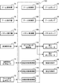
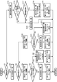
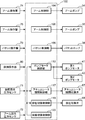
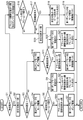
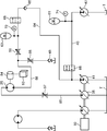
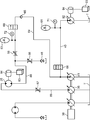
- 1 is a circuit diagram showing a hydraulic drive device according to a first embodiment of the present invention. It is a block diagram which shows the function structure of the controller contained in the hydraulic drive device which concerns on the said 1st Embodiment. It is a flowchart which shows the control operation of the controller which concerns on the said 1st Embodiment. It is a circuit diagram which shows the hydraulic drive device which concerns on the 2nd Embodiment of this invention. It is a block diagram which shows the function structure of the controller contained in the hydraulic drive device which concerns on the said 2nd Embodiment. It is a flowchart which shows the control action of the controller which concerns on the said 2nd Embodiment.
- FIG. 10 is a diagram illustrating an appearance of a hydraulic excavator 10 that is an example of a work machine on which a hydraulic drive device according to each embodiment described below is mounted.
- the excavator 10 is a lower traveling body 12, an upper revolving body 14 that is mounted on the lower traveling body 12 so as to be able to swivel around a vertical axis, and a work that is a working device attached to the upper revolving body 14.
- An attachment 16 includes a traveling device 11 including a pair of crawlers, for example.
- the upper swing body 14 includes a swing frame 13, a cab 15 and a counterweight 17 mounted on the swing frame 13.
- the work attachment 16 includes a boom 18 that is detachably mounted on the upper swing body 14, an arm 20 that is pivotably connected to the tip of the boom 18, and a pivotally connected to the tip of the arm 20. Bucket 22 to be provided.
- the work attachment 16 is provided with a plurality of work hydraulic actuators such as a boom cylinder 24, an arm cylinder 26, and a bucket cylinder 28.
- These cylinders 24, 26 and 28 are each constituted by a hydraulic cylinder with a rod which can be expanded and contracted.
- the boom cylinder 24 is interposed between the boom 18 and the upper swing body 14 so as to expand and contract by receiving the supply of hydraulic oil and rotate the boom 18 in the undulation direction.
- the arm cylinder 26 is interposed between the arm 20 and the boom 18 so as to expand and contract by receiving the supply of hydraulic oil and rotate the arm 20 about the horizontal axis with respect to the boom 18.
- the bucket cylinder 28 is interposed between the bucket 22 and the arm 20 so as to expand and contract by receiving the supply of hydraulic oil and to rotate the bucket 22 around the horizontal axis with respect to the arm 20.
- FIG. 1 shows a hydraulic drive apparatus according to a first embodiment of the present invention that is mounted on the hydraulic excavator.
- the hydraulic drive apparatus includes a plurality of hydraulic actuators including the cylinders 24, 26, and 28, and a plurality of hydraulic oils for driving the hydraulic actuators from the tank and discharging the hydraulic oil to the hydraulic actuators.
- a hydraulic pump, and a prime mover 30 coupled to and driving the plurality of hydraulic pumps.
- the plurality of hydraulic pumps are all of a variable displacement type, and discharge a hydraulic pump for driving the boom cylinder 24 and a hydraulic pump for driving the arm cylinder 26.
- Arm pump 36, bucket pump 38 for driving the bucket cylinder 28 (this bucket pump 38 is not shown in FIG. 1 but shown in FIG. 2 described later), and the upper swing body 14 is turned.
- a first pump motor 41 that discharges hydraulic oil to be connected to a common output shaft 32 connected to the prime mover 30.
- the upper swing body 14 and the boom 18 correspond to a first driving object and a second driving object according to the present invention, respectively, and the boom cylinder 24 is connected to the second driving object.
- the first pump motor 41 is a variable displacement hydraulic pump motor, and changes the capacity of the first pump motor 41 in both directions so that it can be switched between the first pump operating state and the first motor operating state. Has a possible configuration.
- the first pump motor 41 is driven by the prime mover 30 in the first pump operating state and sucks and discharges the hydraulic oil in the tank T. In the first motor operating state, the first pump motor 41 receives supply of the hydraulic oil. Power is generated by being driven, and the motor 30 is assisted by applying the power to the output shaft of the motor 30.
- the plurality of hydraulic actuators are hydraulic actuators for turning the upper turning body 14 in addition to the cylinders 24, 26 and 28, and include the second pump motor 42 shown in FIG. Similar to the first pump motor 41, the second pump motor 42 is a variable displacement hydraulic pump motor, and the second pump motor 42 can be switched between a second motor operating state and a second pump operating state. The motor capacity can be changed in both directions.
- the second pump motor 42 is connected to the first pump motor 41 via the first pump motor line 40.
- the second pump motor 42 receives the supply of hydraulic oil discharged from the first pump motor 41 in the first pump operating state, and thus is the upper rotating body that is the first driving object. Actuate to turn 14.
- the second pump motor 42 operates to suck and discharge the hydraulic oil in the tank T by receiving the supply of turning energy (by inertia) of the upper turning body 14.
- the first pump motor line 40 connects the pump motors 41 and 42 so as to allow the hydraulic oil to flow between the first pump motor 41 and the second pump motor 42.
- a boom drive circuit and an arm drive are respectively provided between the boom cylinder 24 and the boom pump 34, between the arm cylinder 26 and the arm pump 36, and between the bucket cylinder 28 and the bucket pump 38.
- a circuit and bucket drive circuit are provided. These drive circuits supply the hydraulic oil discharged from the pumps 34, 36, 38 to the cylinders 24, 26, 28, and supply the hydraulic oil discharged from the cylinders 24, 26, 28 to the tank T.
- the pumps 34, 36, 38 and the cylinders 24, 26, 28 are connected so that
- FIG. 1 shows a meter-in flow path 46 and a meter-out flow path 47 included in the arm drive circuit, a meter-in flow path 44 included in the boom drive circuit, and a meter-out among the lines included in the drive circuits.
- the flow path 45 and the regeneration flow path 43 are representatively shown.
- the meter-in channel 46 in the arm drive circuit connects the discharge port of the arm pump 36 and the rod side chamber 26r so as to supply the hydraulic oil discharged by the arm pump 36 to the rod side chamber 26r of the arm cylinder 26. Connecting.
- the meter-out flow path 47 connects the head side chamber 26h and the tank T so that the hydraulic oil discharged from the head side chamber 26h of the arm cylinder 26 is returned to the tank T.
- the meter-in passage 44 in the boom drive circuit supplies the hydraulic oil discharged from the boom pump 46 to the head side chamber 24h of the boom cylinder 24, that is, in the direction in which the boom 18 is lowered. So that the discharge port of the boom pump 34 and the rod side chamber 24r are connected.
- the meter-out flow path 45 connects the head side chamber 24h and the tank T so that the hydraulic oil discharged from the head side chamber 24h of the boom cylinder 24 is returned to the tank T.
- the regeneration flow path 43 has a meter-in flow rate (flow rate of hydraulic oil flowing through the meter-in flow path 44) and a meter-out flow rate (meter) due to the difference between the cross-sectional area of the head side chamber 34h and the cross-sectional area of the rod side chamber 34r.
- the meter-out flow path 45 and the meter-out flow path 45 and the meter-in flow path 44 are partly reduced to the meter-in flow path 44.
- a meter-in channel 44 is connected.
- FIG. 1 shows only the flow paths for contracting the arm cylinder 26 and the boom cylinder 24 among the flow paths included in the arm drive circuit and the boom drive circuit.
- the drive circuit also has a flow path (not shown) for extending the arm cylinder 26 and the boom cylinder 24. The same applies to the bucket drive circuit omitted in FIG.
- Each of the plurality of meter-out flow paths including the meter-out flow paths 47 and 45 is provided with a back pressure holding valve 48 for holding a back pressure.
- the meter-in flow path 44, the meter-out flow path 45, and the regeneration line 43 in the boom drive circuit are provided with flow control valves 54, 55, and 53, respectively. Further, the regeneration line 43 is provided with a check valve 56 for preventing the backflow of hydraulic oil from the meter-in channel 44 to the meter-out channel 45.
- This device further includes a regenerative accumulator 61, a boom regenerative accumulator 62, a second pump motor line 64, and a swivel switch as means for regenerating the energy of the upper revolving body 14 and the boom 18.
- a valve 66, a pressure release switching valve 68, a turning regenerative pressure sensor 71, and a boom regenerative pressure sensor 72 are provided.
- the swivel regeneration accumulator 61 is a first accumulator connected to the first pump motor line 40, and receives hydraulic oil discharged from the second pump motor 42 in the second pump operating state to accumulate pressure. To do.
- the boom regeneration accumulator 62 is a second accumulator connected to the meter-out flow path 45 of the boom drive circuit via a regenerative valve 58.
- the regenerative valve 58 is composed of a flow rate control valve, receives an external command signal, and changes the flow rate of hydraulic fluid introduced from the meter-out flow path 47 to the boom regenerative accumulator 62.
- the second pump motor line 64 drives the first pump motor 41 by releasing the pressure of the hydraulic oil stored in the boom regeneration accumulator 62 to the first pump motor 41 in the first motor operating state.
- the boom regeneration accumulator 62 and the first pump motor 41 are connected to enable this.
- a check valve 65 is provided in the middle of the second pump motor line 64, and the check valve 65 prevents backflow from the first pump motor 41 to the boom regeneration accumulator 62.
- the turning switching valve 66 is a line opening / closing switching valve for opening and closing the first pump motor line 40, and is interposed between the turning regeneration accumulator 61 and the first pump motor 41 in the first pump motor line 40. To do.
- the turning switching valve 66 is composed of a two-position electromagnetic switching valve, and has an open position for opening the first pump motor line 40 and a closed position for blocking the first pump motor line 40. Switching between the two positions is performed in accordance with the input switching command signal. That is, it is opened and closed.
- the pressure release switching valve 68 is located at an appropriate portion of the second pump motor line 64 so as to open and close the second pump motor line 64, and between the boom regeneration accumulator 62 and the check valve 65 in FIG. The site is provided.
- the pressure release switching valve 68 is a two-position electromagnetic switching valve, similar to the turning switching valve 66, and opens the second pump motor line 64 and closes the second pump motor line 64. The position is switched between the two positions according to a switching command signal input from the outside.
- the swivel regenerative pressure sensor 71 is a first pressure sensor that detects the pressure of hydraulic oil stored in the swivel regenerative accumulator 61 that is a first accumulator, and generates an electrical signal corresponding to the pressure, that is, a pressure detection signal. Output.
- the boom regenerative pressure sensor 72 is a second pressure sensor that detects the pressure of hydraulic fluid stored in the boom regenerative accumulator 62 that is a second accumulator, and an electric signal corresponding to the pressure, that is, a pressure detection signal. Is generated and output.
- the apparatus further includes a boom operation device 74, an arm operation device 76, a bucket operation device 78, a turning operation device 80, and a controller 100 as shown in FIG.
- Each of the operating devices 74, 76, 78, and 80 generates an operation signal corresponding to an operation member that receives an operation for moving a corresponding drive target, for example, an operation lever, and an operation amount given to the operation lever.
- an operation device main body that inputs to the controller 100.
- the boom operation unit 74 receives an operation for moving the boom 18 in the up or down direction, and inputs a boom operation signal corresponding to the operation to the controller 100.
- the turning operation device 80 receives an operation for turning the upper turning body 14 and inputs a turning operation signal corresponding to the operation to the controller 100.
- the controller 100 controls the drive of the hydraulic actuators based on the operation signals input from the operating devices 74, 76, 78, and 80 and the pressure detection signals input from the pressure sensors 71 and 72.
- the controller 100 includes a boom control unit 104, an arm control unit 106, a bucket control unit 108, a pump motor control unit 110, a turning switching control unit 116, a pressure release switching control unit 118, and a circuit as shown in FIG.
- a switching control unit 120 is provided.
- the boom control unit 104 is configured to control the movement of the boom 18 based on the boom operation signal input from the boom operation unit 74, that is, to control the expansion and contraction of the boom cylinder 24, A stroke of a control valve (not shown) included in the boom drive circuit is operated. That is, the boom control unit 104 adjusts the capacity of the boom pump 34 and opens the control valve so as to move the boom 18 at a specified speed in a direction specified by the boom operation signal.
- the arm control unit 106 and the bucket control unit 108 are based on the arm operation signal and the bucket operation signal input from the arm operation unit 76 and the bucket operation unit 78, respectively.
- the pump motor control unit 110 adjusts the capacity of the pump motors 41 and 42 including switching of the operating states of the first and second pump motors 41 and 42.
- the turning switching control unit 116 inputs a command signal to the turning switching valve 66 to switch the position of the turning switching valve 66, that is, open / close switching, and similarly, the pressure release switching control unit 118 similarly controls the pressure release switching valve.
- a command signal is input to 68, and the position of the pressure release switching valve 68 is switched, that is, the switching is performed.
- control units 110, 116, and 118 constitute a circuit switching unit that switches the circuit state of the hydraulic circuit shown in FIG. 1 in association with the turning drive of the upper turning body 14, and has a plurality of modes.
- the plurality of modes include the following drive mode, first regeneration mode, and second regeneration mode as main modes.
- This drive mode is a mode in which the upper swing body 14 is actively rotated by driving the second pump motor 42 with the hydraulic oil discharged from the first pump motor 41. This mode is suitable for constant speed or accelerated driving.
- the turning switching control unit 116 switches the turning switching valve 66 to the open position to open the first pump motor line 40, and the pressure release switching control unit 118 closes the pressure release switching valve 68.
- the second pump motor line 64 is shut off by switching to a position, and the pump motor control unit 110 sets the first pump motor 41 to the first pump operating state and the second pump motor 42 to the second motor. This is realized by setting the operation state.
- the swirl regeneration accumulator 61 discharges hydraulic oil in addition to the first pump motor 41, thereby assisting in driving the second pump motor 42. .
- This 1st regeneration mode is a mode which regenerates the energy of rotation by the inertia of the upper revolving structure 14 with the 2nd pump motor 42 and the accumulator 61 for revolving regeneration, This mode is suitable for deceleration operation (braking).
- the turning switching control unit 116 closes the turning switching valve 66 to shut off the first pump motor line 40, and the pressure release switching control unit 118 turns the pressure release switching valve 68 on. This is realized by closing the second pump motor line 64 in the closed position and setting the second pump motor 42 in the second pump operating state by the pump motor control unit 110.
- the first regeneration mode is a mode in which the swirl regeneration accumulator 61 is accumulated with hydraulic oil discharged from the second pump motor 42 in the second pump operating state.
- the pump motor control unit 110 brings the first pump motor 41 into the first motor operating state, and the turning switching control unit 116 opens the turning switching valve 66.
- the first pump motor line 40 is opened.
- the first pump motor 41 operates as a motor by the hydraulic oil discharged from the second pump motor 42 (or the regenerative accumulator 61 when the regenerative accumulator 61 is accumulated), That is, power is generated by the energy of the hydraulic oil, and the prime mover 30 is assisted.
- Second regeneration mode In this second regeneration mode, the first pump motor 41 is operated as a motor by releasing the pressure stored in the boom regeneration accumulator 62 toward the first pump motor 41. This is a mode for assisting the prime mover 30 and a mode that can be executed when the upper-part turning body 14 is not turning.
- the turning switching control unit 116 switches the turning switching valve 66 to the closed position
- the release pressure switching control unit 118 switches the release pressure switching valve 68 to the open position
- the pump motor This is realized by the control unit 110 setting the first pump motor 41 to the first motor operating state.
- the circuit switching control unit 120 should be executed out of the plurality of modes based on an operation given to the turning operation unit 80, that is, an operation on the turning drive of the upper turning body 14 that is the first drive target.
- a mode is selected, and a command is input to each of the control units 110, 116, and 118 so as to realize the mode.
- the circuit switching control unit 120 selects the drive mode as a necessary condition that an operation for performing constant speed operation or acceleration for turning of the upper turning body 14 is given to the turning operation unit 80, and
- the first regeneration mode is selected on the condition that an operation for decelerating (braking) the turning of the upper turning body 14 is given to the turning operation device 80, and the turning operation of the upper turning body 14 is performed by the turning operation device.
- the second regeneration mode is selected on the condition that it is not given to 80. In this embodiment, details of conditions for selecting the modes other than the necessary conditions will be described later.
- FIG. 3 shows a calculation control operation actually performed by the controller 100 for the turning drive and regeneration of the upper turning body 14.
- the circuit switching control unit 120 of the controller 100 first determines whether or not a turning operation is given, that is, whether or not any operation is given to the operation lever of the turning operation unit 80 (step S1). . Since any mode selected when the turning operation is given (YES in step S1) requires the second pump motor line 64 to be shut off, the circuit switching control unit 120 closes the pressure release switching valve 68. The release pressure switching control unit 118 is caused to output a command signal so as to switch to the position (step S2).
- the circuit switching control unit 120 is in principle for realizing the drive mode.
- the second pump motor 42 is turned on (step S4), and the turning switch valve 66 is switched to the open position to open the first pump motor line 40 (step S4).
- step S6 Further, in order to drive the first pump motor 41 as a pump by the prime mover 30, a command is issued to switch it to the first pump operating state (step S7).
- the first pump motor 41 driven by the prime mover 30 sucks the hydraulic oil in the tank and supplies it to the second pump motor 42 through the first pump motor line 40, and receives the supplied second pump.
- the motor 42 operates as a motor to rotate the upper swing body 14.
- the circuit The switching control unit 120 is exceptionally configured to execute an assist mode in which the second pump motor 42 is driven using the pressure in the turning regeneration accumulator 61, that is, from the turning regeneration accumulator 61 to the second state.
- a command for switching the turning switching valve 66 to the closed position is issued (step S8).
- the capacity of the first pump motor 41 is preferably set to 0 (step S9).
- the pump motor control unit 110 adjusts the capacities of the first and second pump motors 41 and 42.
- the control serving as a basis for adjusting the capacity can be appropriately selected.
- the output torque of the second pump motor 42 is made constant after adjusting the capacity of the first pump motor 41 so that the pressure of the hydraulic oil discharged from the first pump motor 41 (pump pressure) is controlled to be constant.
- the capacity of the second pump motor 42 is adjusted so as to be controlled.
- the circuit switching control unit 120 issues a command for realizing the first regeneration mode in principle.
- the second pump motor 42 is set to the second pump operating state (step S10), and the command for switching the turning switch valve 66 to the closed position to shut off the first pump motor line 40 is commanded. Is performed (step S12).
- the second pump motor 42 performs a pump operation in which the hydraulic oil in the tank T is sucked and discharged by the energy of the turning due to the inertia of the upper turning body 14, and the discharged hydraulic oil is used for the turning regeneration.
- the accumulator 61 receives and accumulates pressure.
- step S11 when the load on the prime mover 30 is larger than a certain value (YES in step S11), the circuit switching control unit 120 turns to assist the prime mover 30 using the hydraulic oil discharged from the second pump motor 42.
- a command for switching the switching valve 66 to the open position (step S13) and switching the first pump motor 41 to the first motor operating state is issued (step S14).
- the hydraulic oil discharged from the second pump motor 42 is supplied to the first pump motor 41 to operate the first pump motor 41 as a motor, that is, to cause the first pump motor 41 to generate power,
- the prime mover 30 is assisted by this power.
- the circuit switching control unit 120 blocks the first pump motor line 40. Therefore, a command for switching the turning switching valve 66 to the closed position is issued (step S15). Further, when the predetermined regeneration condition is satisfied, specifically, the condition that the boom regeneration accumulator 62 is sufficiently accumulating (the condition that the pressure detected by the boom regeneration pressure sensor 61 is equal to or greater than a certain value) and the prime mover 30. Circuit switching control unit 120 opens the pressure release switching valve 68 to realize the second regeneration mode when both of the conditions that the load is equal to or greater than a certain value are satisfied (both YES in steps S16 and S17).
- a command for opening the second pump motor line 64 and a command for switching the first pump motor 41 to the first motor operating state are issued (steps S18 and S19).
- the pressure of the hydraulic oil stored in the boom regeneration accumulator 62 is released to the first pump motor 41 in the first motor operating state, whereby the first pump motor 41 is moved to the motor. To assist the prime mover 30.
- the circuit switching control unit 120 issues a command to switch the pressure release switching valve 68 to the closed position (step S20).
- the hydraulic oil stored in the boom regeneration accumulator 62 can be introduced into the first pump motor 41 for turning driving through the second pump motor line 64.
- the boom cylinder 24 as an actuator can regenerate the energy of both the upper swing body 14 as the first drive target and the boom 18 as the second drive target without using an expensive pump motor. It is.
- the more the number of the plurality of hydraulic pumps the more the so-called accompanying loss, that is, the pump motor used. Since the energy loss due to the rotation of pump motors that are not used together increases, the advantage of reducing the number of pump motors is great.
- the turning switching valve 66 is switched to the closed position in the second regeneration mode or the normal operation mode, so that the pressure in the turning regeneration accumulator 61 as the first accumulator is maintained.
- the pressure holding valve functions as a pressure holding valve that blocks the pressure release from the turning regeneration accumulator 61 to the first pump motor 41.
- the function required for this pressure holding valve is controlled by a valve other than the turning switching valve 66. Can also be realized.
- FIG. 4 An example thereof is shown in FIG. 4 as a second embodiment.
- the apparatus according to the second embodiment includes an accumulator opening / closing switching valve 67 instead of the turning switching valve 66.
- the accumulator opening / closing switching valve 67 is provided at a position between the first pump motor line 40 and the regenerative accumulator 61 that is the first accumulator.
- the accumulator opening / closing switching valve 67 is constituted by a two-position electromagnetic switching valve, similar to the turning switching valve 66, and shuts off from the open position communicating between the first pump motor line 40 and the turning regeneration accumulator 61. And a blocking position.
- the regenerative pressure sensor 71 according to the second embodiment is provided at a position closer to the regenerative accumulator 61 than the accumulator open / close switching valve 67 is.
- FIG. 5 shows a controller 100 provided in the apparatus according to the second embodiment.
- the controller 100 includes an accumulator opening / closing control unit 117 that switches the position of the accumulator opening / closing switching valve 67 in place of the turning switching control unit 116.
- the accumulator opening / closing control unit 117 opens the turning regeneration accumulator opening / closing switching valve 67 so that the hydraulic oil discharged from the second pump motor 42 in the second pump operating state is supplied to the turning regeneration accumulator 61.
- the accumulator open / close switching valve 67 is closed to maintain the pressure in the swivel regeneration accumulator 61 and from the boom regeneration accumulator 62 to the first pump motor 41. It is possible to more reliably prevent the supplied hydraulic oil from flowing into the regenerative accumulator side.
- the controller 100 according to the second embodiment has a circuit switching control unit 120 similar to the controller 100 according to the first embodiment, and the circuit switching control unit 120 is the same as in the first embodiment. Control. However, in the circuit according to the second embodiment, since the first pump motor line 40 that connects the first and second pump motors 41 and 42 is always in communication, the operation performed by the controller 100 is as follows. The following points (a) to (c) are different from the operation according to the first embodiment.
- step S3 When a constant speed turning or turning acceleration operation is performed (YES in step S3) and the turning regeneration accumulator 61 is not sufficiently accumulated (NO in step S5), the circuit switching control unit 120 is connected to the accumulator.
- the opening / closing control unit 117 is instructed to switch the position of the accumulator opening / closing switching valve 67 to the closed position (step S6A).
- step S6A the hydraulic oil discharged from the first pump motor 41 can be supplied to the second pump motor 42 without being introduced into the rotation regeneration accumulator 61.
- step S5 when the accumulator 61 for turning regeneration is sufficiently accumulated (YES in step S5), the circuit switching control unit 120 adds / closes the accumulator in addition to a command (step S9) for setting the capacity of the first pump motor 41 to zero.
- the controller 117 is instructed to switch the position of the accumulator opening / closing switching valve 67 to the open position (step S21). As a result, the hydraulic oil can be supplied from the turning regeneration accumulator 61 to the second pump motor 42.
- step S3 When the turning deceleration operation is performed (NO in step S3) and the load of the prime mover 30 is less than a certain value (NO in step S11), the circuit switching control unit 120 increases the capacity of the first pump motor 41. A command is issued to switch the accumulator open / close switching valve 67 to the open position (step S23). As a result, the hydraulic oil discharged from the second pump motor 42 can be introduced into the rotation regeneration accumulator 61.
- step S24 the circuit switching control unit 120 issues a command to switch the accumulator opening / closing switching valve 67 to the closed position (step S24). Accordingly, the hydraulic oil discharged from the second pump motor 42 can be used for driving the first pump motor 41 as a motor without being introduced into the regenerative accumulator 61.
- step S1 When the turning operation is not performed (NO in step S1), the circuit switching control unit 120 supplies the hydraulic oil supplied from the boom regeneration accumulator 62 to the first pump motor 41 to the rotation regeneration accumulator 61. And the accumulator opening / closing switching valve 67 is switched to the closed position and the capacity (displacement volume) of the second pump motor 42 is set to 0 to prevent the introduction of the gas and the inflow into the tank T through the second pump motor 42. A command for putting the second pump motor 42 into a substantially shut-off state is issued (step S25).
- the turning switching valve 66 and the accumulator opening / closing switching valve 67 described above have a closed position that completely shuts off the first pump motor 41 and the turning regeneration accumulator 61.
- the turning regeneration accumulator 61 has a closed position. Since the operating pressure of the boom regeneration accumulator 62 is sufficiently higher than the operation pressure of the boom regeneration accumulator 62, even if the pressure holding valve does not have the closed position, the boom regeneration accumulator 62 is connected to the swivel regeneration accumulator 61. It is possible to prevent the inflow of hydraulic oil.
- the pressure holding valve may be, for example, a check valve 82 as shown in FIG. 7 as the third embodiment.
- the check valve 82 is provided in the first pump motor line 40 at a position between the rotation regeneration accumulator 61 and the first pump motor 41, and the first pump motor 41 is connected to the second pump motor 42. It has a function of permitting the flow of hydraulic oil toward it and blocking the flow of hydraulic oil from the swivel regeneration accumulator 61 to the first pump motor 41 and maintaining the pressure in the swivel regeneration accumulator 61.
- regeneration is performed by supplying hydraulic oil to the first pump motor 41 from the second pump motor 42 or the swivel regeneration accumulator 61 and driving the first pump motor 41 as a motor.
- regeneration is possible by introducing the hydraulic oil discharged from the second pump motor 42 into the turning regeneration accumulator 61.
- the first drive target to which the second pump motor according to the present invention is connected and the second drive target to which the regeneration target hydraulic actuator is connected are not limited to the upper swing body 14 and the boom 18, respectively.
- FIG. 8 shows a hydraulic drive apparatus according to the fourth embodiment.
- This device includes a winch motor 25 that rotates a winch drum 84 for raising and lowering a suspended load 83 in a crane, instead of the boom cylinder 24, as the regeneration target hydraulic actuator, and replaces the boom pump 34 with a winch pump. 35.
- the winch motor 25 is constituted by a hydraulic motor, and is connected to the winch pump 35 via a meter-in flow path 85 including a flow control valve 87 and a tank via a meter-out flow path 88 including a flow control valve 87. Connected to T.
- a winch regeneration accumulator 63 as a second accumulator is connected to an appropriate position of the meter-out flow path 88, and the meter-out flow path from the winch motor 25 when the suspended load 83 is lowered, that is, when it is driven to lower.
- the pressure stored in the accumulator 63 for regenerating the winch is discharged toward the first pump motor 41 through the second pump motor line 64 and the pressure release switching valve 68 as in the first embodiment, and the first pump The energy can be regenerated by operating the motor 41 as a motor.
- FIG. 9 shows a hydraulic drive apparatus according to the fifth embodiment.
- This apparatus replaces the second pump motor 42 for turning driving according to the fourth embodiment, and a second pump motor 92 for driving winch for driving a winch drum 94 different from the winch drum 84. It comprises.
- the second pump motor 92 can be switched between a second pump operating state and a second motor operating state, and the second motor In the operating state, the hydraulic oil is supplied from the first pump motor 41 to drive the winch drum 94 in the winding direction, for example, and in the second pump operating state, the pump is driven by the rotational energy of the winch drum 94 that rotates in the lowering direction. Operates as That is, the hydraulic oil in the tank T is sucked and discharged.
- the pressure release switching valve 68 is switched to the open position and the winch regeneration accumulator 63 is operated. It is possible to regenerate the energy stored in the winch regeneration accumulator 63 by releasing the pressure to the first pump motor 41.
- a plurality of hydraulic pumps are connected in series to the common output shaft 32, but the plurality of hydraulic pumps may be connected in parallel to a common prime mover via a power device. Alternatively, the plurality of hydraulic pumps may be distributed and connected to a plurality of prime movers.
- the charge pump or the low pressure accumulator may be connected to a low pressure line between the second pump motor 42 and the tank T shown in FIG.
- a hydraulic drive device for hydraulically driving a first drive object and a second drive object included in a work machine, and the first drive object is driven by being driven by a prime mover.
- a first pump motor that can be switched between a first pump operating state for sucking and discharging hydraulic oil for discharge from a tank and a first motor operating state for receiving power supplied to generate power, and the first drive target
- the second motor operating state that moves the first driving object in response to the supply of hydraulic oil discharged from the first pump motor in the first pump operating state and the energy of the first driving object
- a second pump motor that can be switched to a second pump operating state that operates to suck and discharge hydraulic oil from the tank by receiving supply, and from the first pump motor to the second pump.
- a first pump motor line that interconnects the first pump motor and the second pump motor so as to enable the supply of hydraulic oil to the booster motor, the first pump motor line, and the second pump motor line.
- a first accumulator for receiving and accumulating hydraulic oil discharged from the second pump motor in a pump operating state; and a pressure in the first accumulator interposed between the first accumulator and the first pump motor.
- a pressure holding valve having a function of preventing pressure release from the first accumulator to the first pump motor so as to hold the pressure, and the second drive connected to the second drive object and receiving the supply of hydraulic oil
- a regenerative hydraulic actuator that moves a target, and a hydraulic pump that sucks and discharges hydraulic fluid to be supplied to the regenerative hydraulic actuator from a tank;
- a second accumulator that receives and accumulates hydraulic fluid that is boosted by the energy of the second drive target and discharged from the regeneration target hydraulic actuator, and the pressure of the hydraulic fluid stored in the second accumulator is the first motor.
- a second pump motor line connecting the second accumulator to the first pump motor so as to be released to the first pump motor in operation and to drive the first pump motor;
- the pump motor line is opened and switched between an open state in which pressure can be released from the second accumulator to the first pump motor and a closed state in which the second pump motor line is shut off to prevent the pressure release.
- a pressure release switching valve capable of performing the above operation.
- the second pump motor is driven by the hydraulic oil discharged from the first pump motor or the hydraulic oil discharged from the first accumulator by a combination of switching between the two and the opening / closing switching of the pressure release switching valve.
- the first pump motor can be driven by the hydraulic oil discharged from the second accumulator.
- the regeneration target hydraulic actuator regenerates the energy of both the regeneration target hydraulic actuator and the first hydraulic actuator with a simple and low-cost configuration that does not require an expensive pump motor. Make it possible.
- the release pressure switching valve is closed, the first pump motor is in the first pump operating state, and the second pump motor is in the second motor operating state, It is possible to move the first drive object connected to the second pump motor by driving the second pump motor with the hydraulic oil discharged from the first pump motor.
- the second pump motor is energized by the energy supplied from the regeneration target hydraulic actuator to the second pump motor.
- the hydraulic oil discharged from the second pump motor is introduced into the first accumulator, that is, the energy can be regenerated by accumulating pressure in the first accumulator.
- the first pump is released by releasing pressure from the second accumulator to the first pump motor. It is also possible to operate the motor, that is, to regenerate the energy of the regeneration target hydraulic actuator.
- the pressure holding valve is provided at a position between the first accumulator and the first pump motor in the first pump motor line, and is in an open state communicating with the first pump motor line.
- a line opening / closing switching valve that can be switched to a closed state that shuts off the first pump motor line is preferable. It is possible to drive the first pump motor by the pressure accumulated in the first accumulator by opening the line open / close switching valve and setting the first pump motor to the first motor operating state. Furthermore, by setting the second pump motor to the second pump operating state, it is possible to drive the first pump motor with hydraulic oil discharged from the second pump motor. On the other hand, by closing the open / close switching valve, it is possible to more reliably prevent the hydraulic oil supplied from the second accumulator to the first pump motor from flowing into the first accumulator. is there.
- the pressure holding valve is provided at a position between the first pump motor line and the first accumulator, and is in an open state that communicates between the first pump motor line and the first accumulator.
- An accumulator opening / closing switching valve that can be switched to a shut-off state that shuts off between one pump motor line and the first accumulator may be used.
- the pressure holding valve is the accumulator opening / closing switching valve
- the first pump motor and the second pump motor are always communicated with each other.
- the hydraulic fluid supplied from the second accumulator to the first pump motor is changed to the second pump motor by setting the capacity of the pump motor (displacement volume) to 0 and bringing the second pump motor into a substantially shut-off state. It is also possible to prevent it from flowing into the side.
- the first pressure motor when the operating pressure of the first accumulator is higher than the operating pressure of the second accumulator, the first pressure motor does not have a function of completely shutting off the first pump motor line. It is possible to prevent the hydraulic oil from flowing from the two accumulators to the first accumulator.
- the pressure holding valve is provided, for example, at a position between the first accumulator and the first pump motor in the first pump motor line, and is directed from the first pump motor to the second pump motor. There may be a check valve that allows the flow of hydraulic oil and blocks the flow of hydraulic oil from the first accumulator to the first pump motor.
- the hydraulic drive device further includes a circuit switching unit having a plurality of modes, wherein the plurality of modes closes the pressure release switching valve, sets the first pump motor to the first pump operating state, and A drive mode that allows the second pump motor to be driven by hydraulic oil discharged from the first pump motor by bringing the second pump motor into the second motor operating state; and the pressure release switching valve A first regenerative mode that allows the hydraulic oil discharged by the second pump motor to be introduced into the first accumulator by closing the second pump motor and bringing the second pump motor into the second pump operating state; By opening the pressure release switching valve and setting the first pump motor to the first motor operating state, the first pump motor is moved from the second accumulator.
- the pressure relief to include a second regenerative mode that allows to motor operation the first pump motor, a is preferable.
- the circuit switching unit opens the line opening / closing switching valve in the driving mode and closes the line opening / closing switching valve in the second regeneration mode. It is good to do.
- the circuit switching unit may open the line opening / closing switching valve or may close the line opening / closing switching valve.
- the hydraulic oil discharged from the first accumulator or the operation discharged from the second pump motor It is also possible to drive the first pump motor by supplying oil to the first pump motor.
- the circuit switching unit opens the accumulator on / off switching valve in the first regeneration mode and the accumulator on / off switching valve in the second regeneration mode. It should be closed.
- the circuit switching unit may open or close the accumulator opening / closing switching valve in the drive mode.
- an apparatus includes an operating unit that receives an operation for a command for driving the first driving target, and an operation unit that receives the operation given to the operating unit. It is more preferable to include a circuit switching control unit that switches modes. Specifically, the circuit switching control unit sets the circuit switching unit to the drive mode on the condition that an operation for driving or accelerating the first drive target is given to the operating device. The circuit switching unit is switched to the first regeneration mode on the condition that an operation for decelerating the first drive target is given to the controller, and an operation for driving the first drive target is performed. It is preferable that the circuit switching unit is switched to the second regeneration mode on the condition that the operation unit is not provided.
- the necessary condition for switching to the second regeneration mode further includes that the load of the prime mover driving the first pump motor is a certain level or more.
- the circuit switching unit is switched to the second regeneration mode, that is, the first pump motor is set in the first motor operating state, and the first pump motor is stored in the second accumulator. It is possible to assist the prime mover via the first pump motor.
Landscapes
- Engineering & Computer Science (AREA)
- General Engineering & Computer Science (AREA)
- Mechanical Engineering (AREA)
- Structural Engineering (AREA)
- Civil Engineering (AREA)
- Mining & Mineral Resources (AREA)
- Physics & Mathematics (AREA)
- Fluid Mechanics (AREA)
- Chemical & Material Sciences (AREA)
- Analytical Chemistry (AREA)
- Automation & Control Theory (AREA)
- Fluid-Pressure Circuits (AREA)
- Operation Control Of Excavators (AREA)
Abstract
複数の駆動対象の駆動及びそのエネルギーの回生を簡単な構成で行う油圧駆動装置を提供する。油圧駆動装置は、第1ポンプモータ(41)と、第1ポンプモータ(41)から吐出される作動油によって第1駆動対象を動かす状態と前記第1駆動対象のエネルギーによってポンプとして作動する状態とに切換可能な第2ポンプモータ(42)と、第1及び第2ポンプモータ(41,42)を接続する第1ポンプモータライン(40)と、第1ポンプモータライン(40)に接続される第1アキュムレータ(61)と、第2駆動対象を動かす回生対象油圧アクチュエータ(34)と、回生対象油圧アクチュエータ(34)からの作動油を受け入れる第2アキュムレータ(62)と、第2アキュムレータ(62)を第1ポンプモータ(41)に接続する第2ポンプモータライン(64)と、第2ポンプモータライン(64)を開閉する放圧切換弁(68)と、を備える。
Description
本発明は、油圧ショベル等の作業機械に設けられる油圧駆動装置に関する。
一般に、作業機械に設けられる油圧駆動装置は、作動油を吐出する油圧ポンプと、この油圧ポンプが吐出する作動油の供給を受けて駆動対象を動かすように作動する油圧アクチュエータと、を備えるが、近年は、前記油圧アクチュエータが逆に前記駆動対象から与えられる外力によるエネルギーを回生するために、ポンプ機能とモータ機能とを併有する、いわゆるポンプモータを用いる技術が、知られている。
例えば、特許文献1は、それぞれがいわゆるポンプモータである複数の可逆調整ユニットを備えた装置を開示する。当該装置は、旋回体を旋回させるための旋回駆動回路に設けられる第1可逆調整ユニットE1及び第2可逆調整ユニットE2と、ブームを駆動するためのブームシリンダを含むブーム駆動回路に設けられる第3可逆調整ユニットE3及び第4可逆調整ユニットE4と、を含む。
前記旋回駆動回路において、旋回駆動を行う際には前記第1可逆調整ユニットE1が作動油を吐出するポンプとして作動し、前記第2可逆調整ユニットE2が当該作動油の供給を受けて旋回体を旋回させるモータとして作動する。一方、旋回減速時には前記第2可逆調整ユニットE2が旋回体の回転エネルギーによって高圧の作動油を吐出するポンプとして作動し、当該高圧の作動油は前記旋回駆動回路に設けられた蓄圧器Sprに蓄えられる。この蓄圧器Sprに蓄えられた高圧油は、必要に応じて前記可逆調整ユニットE1を介してエンジンをアシストする動力として用いられ、これにより、前記旋回減速時における旋回体の回転エネルギーが回生される。
前記ブーム駆動回路では、ブーム下げ操作時にブームシリンダから排出される作動油のエネルギーが前記可逆調整ユニットE3,E4を介して当該ブーム駆動回路に設けられた蓄圧器Sphに蓄えられ、あるいは前記旋回駆動回路の蓄圧器Sprに供給されることも可能である。一方、ブーム上げ操作時には前記蓄圧器Spr,Sphに蓄えられたエネルギーが前記可逆調整ユニットE3,E4,E1を介して動力に変換され、エンジンのアシストに寄与する。
しかし、前記可逆調整ユニットを構成するポンプモータは、油圧ポンプとしての機能と油圧モータとしての機能を併有するため、一般の油圧ポンプや油圧モータに比べて高価である。前記特許文献1に記載される装置では、旋回駆動回路及びブーム駆動回路のそれぞれが複数のポンプモータを具備する必要があるため、当該ポンプモータの必要台数が多く、その分コスト及び設置スペースの著しい増大は避けられない。
本発明は、作業機械における複数の駆動対象の駆動及びそのエネルギーの回生を簡単かつ低コストの構成で行うことが可能な油圧駆動装置を提供することを目的とする。
提供されるのは、作業機械に含まれる第1駆動対象及び第2駆動対象をそれぞれ油圧で駆動するための油圧駆動装置であって、原動機によって駆動されることにより前記第1駆動対象を駆動するための作動油をタンクから吸入して吐出する第1ポンプ作動状態と作動油の供給を受けて動力を生成する第1モータ作動状態とに切換可能な第1ポンプモータと、前記第1駆動対象に連結され、前記第1ポンプ作動状態にある前記第1ポンプモータから吐出される作動油の供給を受けて前記第1駆動対象を動かす第2モータ作動状態と前記第1駆動対象のもつエネルギーの供給を受けることによりタンクから作動油を吸入して吐出するように作動する第2ポンプ作動状態とに切換可能な第2ポンプモータと、前記第1ポンプモータから前記第2ポンプモータへの作動油の供給を可能にするように当該第1ポンプモータと当該第2ポンプモータとを相互に接続する第1ポンプモータラインと、前記第1ポンプモータラインに接続され、前記第2ポンプ作動状態にある前記第2ポンプモータから吐出される作動油を受け入れて蓄圧する第1アキュムレータと、前記第1アキュムレータと前記第1ポンプモータとの間に介在し、前記第1アキュムレータ内の圧力を保持するように当該第1アキュムレータから前記第1ポンプモータへの放圧を阻止する機能をもつ圧力保持弁と、前記第2駆動対象に連結され、作動油の供給を受けて当該第2駆動対象を動かす回生対象油圧アクチュエータと、前記回生対象油圧アクチュエータに供給されるべき作動油をタンクから吸入して吐出する油圧ポンプと、前記第2駆動対象のもつエネルギーにより昇圧されて前記回生対象油圧アクチュエータから排出される作動油を受け入れて蓄圧する第2アキュムレータと、前記第2アキュムレータに蓄えられた作動油の圧力が前記第1モータ作動状態にある第1ポンプモータに放たれて当該第1ポンプモータを駆動することを可能にするように当該第2アキュムレータを当該第1ポンプモータに接続する第2ポンプモータラインと、当該第2ポンプモータラインを開通して前記第2アキュムレータから前記第1ポンプモータへの放圧を可能にする開状態と当該第2ポンプモータラインを遮断して当該放圧を阻止する閉状態とに切換えられることが可能な放圧切換弁と、を備える。
本発明の好ましい実施の形態を、図面を参照しながら説明する。
図10は、以下に示す各実施の形態に係る油圧駆動装置が搭載される作業機械の例である油圧ショベル10の外観を示す図である。この油圧ショベル10は、下部走行体12と、当該下部走行体12の上に縦軸回りに旋回可能に搭載される上部旋回体14と、当該上部旋回体14に装着される作業装置である作業アタッチメント16と、を備える。前記下部走行体12は、例えば一対のクローラを含む走行装置11を有する。前記上部旋回体14は、旋回フレーム13と、当該旋回フレーム13上に搭載される運転室15及びカウンタウェイト17と、を含む。前記作業アタッチメント16は、前記上部旋回体14に起伏可能に装着されるブーム18と、このブーム18の先端に回動可能に連結されるアーム20と、このアーム20の先端に回動可能に連結されるバケット22と、を備える。
前記作業アタッチメント16には、複数の作業用油圧アクチュエータであるブームシリンダ24、アームシリンダ26、及びバケットシリンダ28が装着される。これらのシリンダ24,26,28は、それぞれ伸縮可能なロッド付油圧シリンダにより構成される。前記ブームシリンダ24は、作動油の供給を受けることにより伸縮して前記ブーム18を起伏方向に回動させるように、当該ブーム18と前記上部旋回体14との間に介在する。前記アームシリンダ26は、作動油の供給を受けることにより伸縮して前記アーム20を前記ブーム18に対して水平軸回りに回動させるように、当該アーム20と当該ブーム18との間に介在する。バケットシリンダ28は、作動油の供給を受けることにより伸縮して前記バケット22を前記アーム20に対して水平軸回りに回動させるように、当該バケット22と当該アーム20との間に介在する。
図1は、本発明の第1の実施の形態に係る油圧駆動装置であって前記油圧ショベルに搭載されるものを示す。この油圧駆動装置は、前記各シリンダ24,26,28を含む複数の油圧アクチュエータと、当該複数の油圧アクチュエータをそれぞれ駆動するための作動油をタンク内から吸入して当該油圧アクチュエータに吐出する複数の油圧ポンプと、当該複数の油圧ポンプに連結されてこれらを駆動する原動機30と、を備える。前記複数の油圧ポンプは、いずれも可変容量型のものであって、前記ブームシリンダ24を駆動するための作動油を吐出するブームポンプ34と、前記アームシリンダ26を駆動するための作動油を吐出するアームポンプ36と、前記バケットシリンダ28を駆動するためのバケットポンプ38(このバケットポンプ38は図1には示されていないが後述の図2に示される)と、前記上部旋回体14を旋回させるための作動油を吐出する第1ポンプモータ41と、を含み、これらが前記原動機30につながる共通の出力軸32に連結されている。
この実施の形態において、前記上部旋回体14及び前記ブーム18はそれぞれ本発明に係る第1駆動対象及び第2駆動対象に相当し、前記ブームシリンダ24は当該第2駆動対象に連結されてこれを動かす回生対象油圧アクチュエータに相当する。従って、前記ブームポンプ34は当該回生対象油圧アクチュエータに供給すべき作動油を吐出する油圧ポンプに相当する。
第1ポンプモータ41は、可変容量型の油圧ポンプモータであって、第1ポンプ作動状態と第1モータ作動状態とに切換可能となるように当該第1ポンプモータ41の容量を両方向に変更することが可能な構成を有する。第1ポンプモータ41は、前記第1ポンプ作動状態では、前記原動機30により駆動されてタンクT内の作動油を吸入して吐出し、前記第1モータ作動状態では、作動油の供給を受けて駆動されることにより動力を生成し、当該動力を前記原動機30の出力軸に与えることにより当該原動機30をアシストする。
前記複数の油圧アクチュエータは、前記各シリンダ24,26,28に加え、前記上部旋回体14を旋回させるための油圧アクチュエータであって図1に示される第2ポンプモータ42を含む。第2ポンプモータ42は、前記第1ポンプモータ41と同様、可変容量型の油圧ポンプモータであって、第2モータ作動状態と第2ポンプ作動状態とに切換可能となるように当該第2ポンプモータの容量を両方向に変更することが可能な構成を有する。
第2ポンプモータ42は、第1ポンプモータライン40を介して前記第1ポンプモータ41に接続される。第2ポンプモータ42は、前記第2モータ作動状態では、前記第1ポンプ作動状態にある前記第1ポンプモータ41が吐出する作動油の供給を受けることにより第1駆動対象である前記上部旋回体14を旋回させるように作動する。第2ポンプモータ42は、前記第2ポンプ作動状態では、前記上部旋回体14のもつ(慣性による)旋回エネルギーの供給を受けることによりタンクT内の作動油を吸引して吐出するように作動する。前記第1ポンプモータライン40は、前記第1ポンプモータ41と前記第2ポンプモータ42との間での作動油の流通を可能にするように両ポンプモータ41,42同士を接続する。
前記ブームシリンダ24と前記ブームポンプ34との間、前記アームシリンダ26と前記アームポンプ36との間、及び前記バケットシリンダ28と前記バケットポンプ38との間には、それぞれ、ブーム駆動回路、アーム駆動回路及びバケット駆動回路が、設けられている。これらの駆動回路は、前記各ポンプ34,36,38から吐出される作動油を前記各シリンダ24,26,28に供給して当該各シリンダ24,26,28から排出された作動油をタンクTに戻すように、当該ポンプ34,36,38と当該各シリンダ24,26,28とを接続する。
図1は、前記各駆動回路に含まれるラインのうち、便宜上、前記アーム駆動回路に含まれるメータイン流路46及びメータアウト流路47と、前記ブーム駆動回路に含まれるメータイン流路44、メータアウト流路45及び再生流路43と、を代表的に示している。
前記アーム駆動回路における前記メータイン流路46は、前記アームポンプ36により吐出される作動油を前記アームシリンダ26のロッド側室26rに供給するように当該アームポンプ36の吐出口と当該ロッド側室26rとを接続する。前記メータアウト流路47は、前記アームシリンダ26のへッド側室26hから排出される作動油をタンクTに戻すように当該へッド側室26hと当該タンクTとを接続する。
前記ブーム駆動回路における前記メータイン流路44は、前記ブームポンプ46により吐出される作動油を前記ブームシリンダ24のへッド側室24hに供給するように、つまりブーム18を下げる方向に前記ブームシリンダ24を作動させるように、当該ブームポンプ34の吐出口と当該ロッド側室24rとを接続する。前記メータアウト流路45は、前記ブームシリンダ24のへッド側室24hから排出される作動油をタンクTに戻すように当該へッド側室24hとタンクTとを接続する。前記再生流路43は、前記へッド側室34hの断面積と前記ロッド側室34rの断面積との差に起因するメータイン流量(メータイン流路44を流れる作動油の流量)とメータアウト流量(メータアウト流路45を流れる作動油の流量)との差を補うべく、前記メータアウト流路45を流れる作動油の一部を前記メータイン流路44に還元するように当該メータアウト流路45と当該メータイン流路44とを接続する。
以上のように、図1は、前記アーム駆動回路及び前記ブーム駆動回路に含まれる流路のうち前記アームシリンダ26及び前記ブームシリンダ24をそれぞれ収縮させるための流路のみを示しているが、当該駆動回路は当該アームシリンダ26及びブームシリンダ24を伸長させるための、図示されない流路も併有している。この点は、図1において省略されているバケット駆動回路についても同様である。
前記メータアウト流路47,45を含む複数のメータアウト流路のそれぞれには、背圧を保持するための背圧保持弁48が設けられている。また、前記ブーム駆動回路における前記メータイン流路44、前記メータアウト流路45及び前記再生ライン43には、それぞれ、流量調節弁54,55,53が設けられている。さらに、前記再生ライン43には、前記メータイン流路44から前記メータアウト流路45への作動油の逆流を防ぐチェック弁56が設けられている。
この装置は、さらに、前記上部旋回体14及び前記ブーム18のもつエネルギーを回生するための手段として、旋回回生用アキュムレータ61と、ブーム回生用アキュムレータ62と、第2ポンプモータライン64と、旋回切換弁66と、放圧切換弁68と、旋回回生圧力センサ71と、ブーム回生圧力センサ72と、を備える。
前記旋回回生用アキュムレータ61は、前記第1ポンプモータライン40に接続される第1アキュムレータであって、前記第2ポンプ作動状態にある前記第2ポンプモータ42から吐出される作動油を受け入れて蓄圧する。
前記ブーム回生用アキュムレータ62は、前記ブーム駆動回路のメータアウト流路45に回生弁58を介して接続される第2アキュムレータであって、前記ブーム18が下げ方向に動く際に前記ブームシリンダ24のへッド側室24hから排出される作動油、すなわち、当該ブーム18から与えられるエネルギーにより昇圧された高圧の作動油、を受け入れて蓄圧する。前記回生弁58は、流量制御弁からなり、外部からの指令信号の入力を受け、前記メータアウト流路47から前記ブーム回生用アキュムレータ62に導入される作動油の流量を変化させる。
前記第2ポンプモータライン64は、前記ブーム回生用アキュムレータ62に蓄えられた作動油の圧力が前記第1モータ作動状態にある第1ポンプモータ41に放たれて当該第1ポンプモータ41を駆動することを可能にするように当該ブーム回生用アキュムレータ62と当該第1ポンプモータ41とを接続する。この第2ポンプモータライン64の途中にはチェック弁65が設けられ、当該チェック弁65は前記第1ポンプモータ41から前記ブーム回生用アキュムレータ62への逆流を阻止する。
前記旋回切換弁66は、前記第1ポンプモータライン40を開閉するライン開閉切換弁であり、当該第1ポンプモータライン40において前記旋回回生用アキュムレータ61と前記第1ポンプモータ41との間に介在する。この旋回切換弁66は、2位置の電磁切換弁からなり、前記第1ポンプモータライン40を開通する開位置と、当該第1ポンプモータライン40を遮断する閉位置と、を有し、外部から入力される切換指令信号に応じて両位置の間で切換えられる。すなわち、開閉される。
前記放圧切換弁68は、前記第2ポンプモータライン64を開閉するように当該第2ポンプモータライン64の適当な部位、図1では前記ブーム回生用アキュムレータ62と前記チェック弁65との間の部位、に設けられる。この放圧切換弁68は、前記旋回切換弁66と同様に2位置の電磁切換弁からなり、前記第2ポンプモータライン64を開通する開位置と、当該第2ポンプモータライン64を遮断する閉位置と、を有し、外部から入力される切換指令信号に応じて両位置の間で切換えられる。
前記旋回回生圧力センサ71は、第1アキュムレータである前記旋回回生用アキュムレータ61に蓄えられる作動油の圧力を検出する第1圧力センサであり、当該圧力に対応する電気信号すなわち圧力検出信号を生成して出力する。同様に、前記ブーム回生圧力センサ72は、第2アキュムレータである前記ブーム回生用アキュムレータ62に蓄えられる作動油の圧力を検出する第2圧力センサであり、当該圧力に対応する電気信号すなわち圧力検出信号を生成して出力する。
この実施の形態に係る装置は、さらに、図2に示すようなブーム操作器74、アーム操作器76、バケット操作器78、旋回操作器80、及びコントローラ100を備える。
前記各操作器74,76,78,80は、対応する駆動対象を動かすための操作を受ける操作部材、例えば操作レバー、と、当該操作レバーに与えられた操作の量に対応した操作信号を生成して前記コントローラ100に入力する操作器本体と、を有する。例えば、前記ブーム操作器74は、ブーム18を上げ方向または下げ方向に動かすための操作を受け、当該操作に対応したブーム操作信号をコントローラ100に入力する。また、前記旋回操作器80は、前記上部旋回体14を旋回させるための操作を受け、当該操作に対応した旋回操作信号をコントローラ100に入力する。
前記コントローラ100は、前記各操作器74,76,78,80により入力される前記操作信号及び前記各圧力センサ71,72により入力される圧力検出信号に基づき、前記各油圧アクチュエータの駆動の制御を行う。具体的に、当該コントローラ100は、図2に示すようなブーム制御部104、アーム制御部106、バケット制御部108、ポンプモータ制御部110、旋回切換制御部116、放圧切換制御部118及び回路切換制御部120を有する。
前記ブーム制御部104は、前記ブーム操作器74から入力されるブーム操作信号に基づき、前記ブーム18の動きを制御すべく、すなわちブームシリンダ24の伸縮を制御すべく、ブームポンプ34の容量と、ブーム駆動回路に含まれる図示されないコントロールバルブのストロークの操作を行う。すなわち、ブーム制御部104は、前記ブーム操作信号により指定された方向に指定された速度でブーム18を動かすべく、前記ブームポンプ34の容量を調節するとともに、前記コントロールバルブの開弁操作を行う。同様に、前記アーム制御部106及び前記バケット制御部108は、前記アーム操作器76及び前記バケット操作器78からそれぞれ入力されるアーム操作信号及びバケット操作信号に基づき、前記アーム20及び前記バケット22の動きを制御すべく、すなわちアームシリンダ26及びバケットシリンダ28の伸縮を制御すべく、アームポンプ36及びバケットポンプ38の容量と、アーム駆動回路及びバケット駆動回路にそれぞれ含まれる図示されないコントロールバルブのストロークの操作をそれぞれ行う。
前記ポンプモータ制御部110は、前記第1及び第2ポンプモータ41,42の作動状態の切換も含めて当該ポンプモータ41,42の容量の調節を行う。前記旋回切換制御部116は、前記旋回切換弁66に指令信号を入力して当該旋回切換弁66の位置の切換すなわち開閉切換を行い、同様に前記放圧切換制御部118は前記放圧切換弁68に指令信号を入力して当該放圧切換弁68の位置の切換すなわち開閉切換を行う。
これらの制御部110,116,118は、上部旋回体14の旋回駆動に関連して図1に示される油圧回路の回路状態を切換える回路切換部を構成するものであって、複数のモードを有する。当該複数のモードは、主たるモードとして以下の駆動モード、第1回生モード、及び第2回生モードを含む。
1)駆動モード
この駆動モードは、第1ポンプモータ41が吐出する作動油によって第2ポンプモータ42を駆動することにより上部旋回体14を積極的に旋回させるモードであり、当該上部旋回体14の旋回の定速運転または加速運転に適したモードである。この駆動モードは、前記旋回切換制御部116が前記旋回切換弁66を開位置に切換えて前記第1ポンプモータライン40を開通させ、前記放圧切換制御部118が前記放圧切換弁68を閉位置に切換えて前記第2ポンプモータライン64を遮断させ、さらに前記ポンプモータ制御部110が前記第1ポンプモータ41を前記第1ポンプ作動状態にするとともに前記第2ポンプモータ42を前記第2モータ作動状態にすることにより、実現される。また、旋回回生用アキュムレータ61に圧油が蓄圧されている場合は、第1ポンプモータ41に加えて旋回回生用アキュムレータ61が作動油を吐出することにより、第2ポンプモータ42の駆動をアシストする。
この駆動モードは、第1ポンプモータ41が吐出する作動油によって第2ポンプモータ42を駆動することにより上部旋回体14を積極的に旋回させるモードであり、当該上部旋回体14の旋回の定速運転または加速運転に適したモードである。この駆動モードは、前記旋回切換制御部116が前記旋回切換弁66を開位置に切換えて前記第1ポンプモータライン40を開通させ、前記放圧切換制御部118が前記放圧切換弁68を閉位置に切換えて前記第2ポンプモータライン64を遮断させ、さらに前記ポンプモータ制御部110が前記第1ポンプモータ41を前記第1ポンプ作動状態にするとともに前記第2ポンプモータ42を前記第2モータ作動状態にすることにより、実現される。また、旋回回生用アキュムレータ61に圧油が蓄圧されている場合は、第1ポンプモータ41に加えて旋回回生用アキュムレータ61が作動油を吐出することにより、第2ポンプモータ42の駆動をアシストする。
2)第1回生モード
この第1回生モードは、前記上部旋回体14の慣性による旋回のエネルギーを前記第2ポンプモータ42及び旋回回生用アキュムレータ61により回生するモードであり、当該上部旋回体14の減速運転(制動)に適したモードである。この第1回生モードは、前記旋回切換制御部116が前記旋回切換弁66を閉位置にして前記第1ポンプモータライン40を遮断させ、前記放圧切換制御部118が前記放圧切換弁68を閉位置にして前記第2ポンプモータライン64を遮断させるとともに、前記ポンプモータ制御部110が前記第2ポンプモータ42を前記第2ポンプ作動状態にすることにより、実現される。すなわち、この第1回生モードは、詳細には、前記第2ポンプ作動状態にある前記第2ポンプモータ42が吐出する作動油によって前記旋回回生用アキュムレータ61を蓄圧するモードである。
この第1回生モードは、前記上部旋回体14の慣性による旋回のエネルギーを前記第2ポンプモータ42及び旋回回生用アキュムレータ61により回生するモードであり、当該上部旋回体14の減速運転(制動)に適したモードである。この第1回生モードは、前記旋回切換制御部116が前記旋回切換弁66を閉位置にして前記第1ポンプモータライン40を遮断させ、前記放圧切換制御部118が前記放圧切換弁68を閉位置にして前記第2ポンプモータライン64を遮断させるとともに、前記ポンプモータ制御部110が前記第2ポンプモータ42を前記第2ポンプ作動状態にすることにより、実現される。すなわち、この第1回生モードは、詳細には、前記第2ポンプ作動状態にある前記第2ポンプモータ42が吐出する作動油によって前記旋回回生用アキュムレータ61を蓄圧するモードである。
原動機30の負荷が一定以上の場合、前記ポンプモータ制御部110が前記第1ポンプモータ41を前記第1モータ作動状態にするとともに前記旋回切換制御部116が前記旋回切換弁66を開位置にして前記第1ポンプモータライン40を開通させる。これにより、前記第2ポンプモータ42(前記旋回回生用アキュムレータ61が蓄圧されている場合は当該旋回回生用アキュムレータ61)から吐出される作動油によって、前記第1ポンプモータ41がモータとして作動し、つまり前記作動油のエネルギーによって動力を生成し、前記原動機30のアシストを行う。
3)第2回生モード
この第2回生モードは、前記ブーム回生用アキュムレータ62に蓄えられた圧力を前記第1ポンプモータ41に向けて放圧することにより当該第1ポンプモータ41をモータとして作動させて前記原動機30をアシストするモードであり、前記上部旋回体14の旋回が行われていないときに実行されることが可能なモードである。この第2回生モードは、前記旋回切換制御部116が前記旋回切換弁66を閉位置に切換え、前記放圧切換制御部118が前記放圧切換弁68を開位置に切換え、かつ、前記ポンプモータ制御部110が前記第1ポンプモータ41を前記第1モータ作動状態にすることにより、実現される。
この第2回生モードは、前記ブーム回生用アキュムレータ62に蓄えられた圧力を前記第1ポンプモータ41に向けて放圧することにより当該第1ポンプモータ41をモータとして作動させて前記原動機30をアシストするモードであり、前記上部旋回体14の旋回が行われていないときに実行されることが可能なモードである。この第2回生モードは、前記旋回切換制御部116が前記旋回切換弁66を閉位置に切換え、前記放圧切換制御部118が前記放圧切換弁68を開位置に切換え、かつ、前記ポンプモータ制御部110が前記第1ポンプモータ41を前記第1モータ作動状態にすることにより、実現される。
前記回路切換制御部120は、前記旋回操作器80に与えられる操作、すなわち、第1駆動対象である上部旋回体14の旋回駆動についての操作、に基づき、前記複数のモードのうち実行されるべきモードを選択し、当該モードを実現するように前記各制御部110,116,118に指令を入力する。この実施の形態に係る回路切換制御部120は、前記上部旋回体14の旋回について定速運転または加速を行う操作が旋回操作器80に与えられることを必要条件として前記駆動モードを選択し、前記上部旋回体14の旋回について減速(制動)を行う操作が旋回操作器80に与えられることを必要条件として前記第1回生モードを選択し、前記上部旋回体14の旋回についての操作が旋回操作器80に与えられていないことを必要条件として前記第2回生モードを選択する。この実施の形態において前記各必要条件以外に前記各モードが選択されるための条件の詳細については後述する。
図3は、前記上部旋回体14の旋回駆動及び回生について前記コントローラ100が実際に行う演算制御動作を示す。
前記コントローラ100の回路切換制御部120は、まず、旋回操作が与えられているか否か、すなわち前記旋回操作器80の操作レバーに何らかの操作が与えられているか否か、を判断する(ステップS1)。当該旋回操作が与えられている場合(ステップS1でYES)に選択されるモードはいずれも第2ポンプモータライン64を遮断することを要するので、回路切換制御部120は放圧切換弁68を閉位置に切換えるように放圧切換制御部118に指令信号を出力させる(ステップS2)。
前記旋回操作が、上部旋回体14を定速で旋回させるための操作、あるいは当該旋回を加速させる操作である場合(ステップS3でYES)、回路切換制御部120は原則として駆動モードを実現するための指令を行う。具体的には、第2ポンプモータ42をモータとして駆動すべくこれを第2モータ作動状態にし(ステップS4)、第1ポンプモータライン40を開通すべく旋回切換弁66を開位置に切換え(ステップS6)、さらに原動機30によって第1ポンプモータ41をポンプとして駆動すべくこれを第1ポンプ作動状態に切換える(ステップS7)ための指令を行う。この駆動モードでは、原動機30により駆動される第1ポンプモータ41がタンク内の作動油を吸入して第1ポンプモータライン40を通じて第2ポンプモータ42に供給し、この供給を受けた第2ポンプモータ42はモータとして作動して上部旋回体14を旋回させる。
ただし、前記旋回回生用アキュムレータ61が十分に蓄圧している場合(ステップS5でYES)、すなわち、前記旋回回生圧力センサ71により検出される旋回回生用アキュムレータ61内の圧力が一定以上の場合、回路切換制御部120は、例外的に、当該旋回回生用アキュムレータ61内の圧力を利用して前記第2ポンプモータ42の駆動を行うアシストモードを実行すべく、すなわち当該旋回回生用アキュムレータ61から第2ポンプモータ42への作動油の吐出を行わせるべく、旋回切換弁66を閉位置に切換えさせる指令を行う(ステップS8)。この場合、第1ポンプモータ41の容量は0にすることが好ましい(ステップS9)。
前記駆動モードにおいて、前記ポンプモータ制御部110は、前記第1及び第2ポンプモータ41,42の容量を調節する。この容量の調節のベースとなる制御については適宜選定されることが可能である。例えば、第1ポンプモータ41の吐出する作動油の圧力(ポンプ圧)を一定に制御するように当該第1ポンプモータ41の容量を調節した上で、第2ポンプモータ42の出力トルクを一定に制御するように当該第2ポンプモータ42の容量を調節することが行われる。
一方、前記旋回操作が、上部旋回体14の旋回を減速させる操作である場合(ステップS3でNO)、回路切換制御部120は原則として第1回生モードを実現するための指令を行う。具体的には、第2ポンプモータ42をポンプとして駆動すべくこれを第2ポンプ作動状態にし(ステップS10)、第1ポンプモータライン40を遮断すべく旋回切換弁66を閉位置に切換えさせる指令を行う(ステップS12)。このモードでは、上部旋回体14の慣性による旋回のエネルギーによって前記第2ポンプモータ42がタンクT内の作動油を吸入して吐出するポンプ動作を行い、その吐出された作動油を前記旋回回生用アキュムレータ61が受け入れて蓄圧を行う。
ただし、前記原動機30の負荷が一定以上大きい場合(ステップS11でYES)、前記第2ポンプモータ42の吐出する作動油を利用して当該原動機30をアシストすべく、回路切換制御部120は、旋回切換弁66を開位置に切換えさせ(ステップS13)かつ第1ポンプモータ41を第1モータ作動状態に切換えさせる指令を行う(ステップS14)。このモードでは、前記第2ポンプモータ42の吐出する作動油が第1ポンプモータ41に供給されて当該第1ポンプモータ41をモータとして作動させ、つまり当該第1ポンプモータ41に動力を生成させ、この動力によって原動機30のアシストを行わせる。
前記旋回操作が行われていない場合、すなわち、前記旋回検出器80に操作が与えられていない場合(ステップS1でNO)、前記回路切換制御部120は、前記第1ポンプモータライン40を遮断すべく前記旋回切換弁66を閉位置に切換えさせる指令を行う(ステップS15)。さらに、所定の回生条件を満たす場合、具体的には、ブーム回生用アキュムレータ62が十分蓄圧しているという条件(前記ブーム回生圧力センサ61が検出する圧力が一定以上であるという条件)及び原動機30の負荷が一定以上であるという条件をいずれも満たす場合に(ステップS16,S17でともにYES)、第2回生モードを実現すべく、前記回路切換制御部120は、放圧切換弁68を開位置にして前記第2ポンプモータライン64を開通させるための指令及び第1ポンプモータ41を第1モータ作動状態に切換えさせる指令を行う(ステップS18,S19)。この第2回生モードでは、前記ブーム回生用アキュムレータ62に蓄えられた作動油の圧力が前記第1モータ作動状態にある前記第1ポンプモータ41に放たれ、これにより当該第1ポンプモータ41がモータとして作動して原動機30のアシストを行う。
ただし、前記所定の回生条件を満たしていない場合、すなわち、ブーム回生用アキュムレータ62が十分に蓄圧されていないか、あるいは原動機30の負荷が一定未満の場合(ステップS16,S17の少なくとも一方でNO)、通常作業モードを行うべく、回路切換制御部120は、前記放圧切換弁68を閉位置に切換えるような指令を行う(ステップS20)。
この通常作業モードにおいて、ブーム18を下げ方向に動かすようにブームシリンダ24が収縮する際に、当該ブーム18に作用する重力のエネルギーによってブームシリンダ24のへッド側室24hから高圧の作動油が吐出され、その少なくとも一部が前記ブーム回生用アキュムレータ62に導入される。このようにしてブーム回生用アキュムレータ62での蓄圧が行われ、そのエネルギーが前記第2回生モードにおいて前記第1ポンプモータ41を介する原動機30のアシストに供される。
以上説明した装置によれば、ブーム回生用アキュムレータ62に蓄えられた作動油を第2ポンプモータライン64を通じて旋回駆動のための第1ポンプモータ41に導入することが可能であるから、回生対象油圧アクチュエータであるブームシリンダ24については高価なポンプモータを用いなくても、第1駆動対象である上部旋回体14及び第2駆動対象であるブーム18のいずれについてもそのエネルギーの回生を行うことが可能である。特に、図1に示されるように共通の出力軸32に複数の油圧ポンプが連結されるものでは、当該複数の油圧ポンプの台数が多いほど、いわゆる連れ回りロス、すなわち、使用されているポンプモータともに使用されていないポンプモータが連れ回りすることによるエネルギーロス、が大きくなるため、前記ポンプモータの台数を減らすことによる利点は大きい。
前記第1の実施の形態において、前記旋回切換弁66は、第2回生モードや通常作業モードにおいて閉位置に切換えられることにより、第1アキュムレータである旋回回生用アキュムレータ61内の圧力を保持するように当該旋回回生用アキュムレータ61から前記第1ポンプモータ41への放圧を阻止する圧力保持弁としての機能を有するが、この圧力保持弁に求められる機能は、前記旋回切換弁66以外の弁によっても実現されることが可能である。
その例を第2の実施の形態として図4に示す。この第2の実施の形態に係る装置は、前記旋回切換弁66に代えてアキュムレータ開閉切換弁67を備える。このアキュムレータ開閉切換弁67は、第1ポンプモータライン40と第1アキュムレータである旋回回生用アキュムレータ61との間の位置に設けられる。アキュムレータ開閉切換弁67は、前記旋回切換弁66と同様に2位置の電磁切換弁により構成され、前記第1ポンプモータライン40と前記旋回回生用アキュムレータ61との間を連通する開位置と遮断する遮断位置とを有する。また、この第2の実施の形態に係る旋回回生圧力センサ71は前記アキュムレータ開閉切換弁67よりも旋回回生用アキュムレータ61に近い位置に設けられる。
図5は、この第2の実施の形態に係る装置に具備されるコントローラ100を示す。このコントローラ100は、前記旋回切換制御部116に代えて前記アキュムレータ開閉切換弁67の位置を切換えるアキュムレータ開閉制御部117を有する。アキュムレータ開閉制御部117は、前記旋回回生用アキュムレータ開閉切換弁67を開位置にすることにより、前記第2ポンプ作動状態にある前記第2ポンプモータ42が吐出する作動油を前記旋回回生用アキュムレータ61に導入することを可能にし、前記アキュムレータ開閉切換弁67を閉位置にすることにより、前記旋回回生用アキュムレータ61内の圧力を保持するとともに、前記ブーム回生用アキュムレータ62から前記第1ポンプモータ41に供給される作動油が前記旋回回生用アキュムレータ側に流れ込むのをより確実に阻止することが可能である。
この第2の実施の形態に係るコントローラ100は、第1の実施の形態に係るコントローラ100と同様に回路切換制御部120を有し、当該回路切換制御部120は第1の実施の形態と同様の制御を行う。ただし、第2の実施の形態に係る回路では前記第1及び第2ポンプモータ41,42を相互に接続する第1ポンプモータライン40が常に連通された状態にあるため、コントローラ100が行う動作は次の点(a)~(c)において第1の実施の形態に係る動作と異なる。
(a)定速旋回または旋回加速の操作が行われ(ステップS3でYES)かつ旋回回生用アキュムレータ61が十分に蓄圧されていない場合に(ステップS5でNO)、回路切換制御部120は、アキュムレータ開閉制御部117にアキュムレータ開閉切換弁67の位置を閉位置に切換えさせる指令を行う(ステップS6A)。これにより、第1ポンプモータ41から吐出される作動油は旋回回生用アキュムレータ61に導入されることなく第2ポンプモータ42に供給されることができる。一方、旋回回生用アキュムレータ61が十分に蓄圧されている場合(ステップS5でYES)、回路切換制御部120は、第1ポンプモータ41の容量を0にさせる指令(ステップS9)に加え、アキュムレータ開閉制御部117にアキュムレータ開閉切換弁67の位置を開位置に切換えさせる指令を行う(ステップS21)。これにより、旋回回生用アキュムレータ61から第2ポンプモータ42への作動油の供給が可能になる。
(b)旋回減速の操作が行われ(ステップS3でNO)、かつ、原動機30の負荷が一定未満の場合(ステップS11でNO)、回路切換制御部120は、第1ポンプモータ41の容量を0にするとともに(ステップS22)アキュムレータ開閉切換弁67を開位置に切換える指令を行う(ステップS23)。これにより、第2ポンプモータ42から吐出される作動油は旋回回生用アキュムレータ61に導入されることができる。一方、原動機30の負荷が一定以上の場合(ステップS11でYES)、回路切換制御部120は、アキュムレータ開閉切換弁67を閉位置に切換えさせる指令を行う(ステップS24)。これにより、第2ポンプモータ42から吐出される作動油が旋回回生用アキュムレータ61に導入されることなく第1ポンプモータ41のモータとしての駆動に供されることができる。
(c)旋回操作が行われていない場合(ステップS1でNO)、回路切換制御部120は、ブーム回生用アキュムレータ62から前記第1ポンプモータ41に供給される作動油の旋回回生用アキュムレータ61への導入や前記第2ポンプモータ42を通じてのタンクTへの流入を確実に防ぐべく、アキュムレータ開閉切換弁67を閉位置に切換えるとともに前記第2ポンプモータ42の容量(押しのけ容積)を0にして当該第2ポンプモータ42を実質上の遮断状態にするための指令を行う(ステップS25)。
以上示した旋回切換弁66及びアキュムレータ開閉切換弁67はいずれも第1ポンプモータ41と旋回回生用アキュムレータ61との間を完全に遮断する閉位置を有するものであるが、一般に旋回回生用アキュムレータ61の運転圧力はブーム回生用アキュムレータ62の運転圧力よりも十分高いため、前記圧力保持弁が前記閉位置を有しないものであっても、前記ブーム回生用アキュムレータ62から前記旋回回生用アキュムレータ61への作動油の流入を阻止することが可能である。当該圧力保持弁は、例えば、第3の実施の形態として図7に示すようなチェック弁82であってもよい。このチェック弁82は、前記第1ポンプモータライン40において前記旋回回生用アキュムレータ61と前記第1ポンプモータ41との間の位置に設けられ、当該第1ポンプモータ41から前記第2ポンプモータ42に向かう作動油の流れは許容しかつ前記旋回回生用アキュムレータ61から前記第1ポンプモータ41への作動油の流れは阻止して当該旋回回生用アキュムレータ61内の圧力を保持する機能を有する。
この第3の実施の形態では、第2ポンプモータ42または旋回回生用アキュムレータ61から第1ポンプモータ41に作動油を供給して当該第1ポンプモータ41をモータとして駆動することによる回生は行われないが、当該第2ポンプモータ42から吐出される作動油を前記旋回回生用アキュムレータ61に導入することによる回生は可能である。
本発明に係る第2ポンプモータが連結される第1駆動対象及び回生対象油圧アクチュエータが連結される第2駆動対象は、それぞれ、前記上部旋回体14及び前記ブーム18に限定されない。
図8は、第4の実施の形態に係る油圧駆動装置を示す。この装置は、前記回生対象油圧アクチュエータとして、前記ブームシリンダ24に代え、クレーンにおいて吊り荷83を昇降させるためのウィンチドラム84を回転させるウィンチモータ25を具備し、前記ブームポンプ34に代えてウィンチポンプ35を具備する。前記ウィンチモータ25は、油圧モータにより構成され、流量制御弁87を含むメータイン流路85を介して前記ウィンチポンプ35に接続されるとともに、流量制御弁87を含むメータアウト流路88を介してタンクTに接続されている。
この装置においても、例えば前記メータアウト流路88の適所に第2アキュムレータであるウィンチ回生用アキュムレータ63を接続して、吊り荷83の降下時すなわち巻下げ駆動時に前記ウィンチモータ25からメータアウト流路88に吐出される高圧の作動油を前記ウィンチ回生用アキュムレータ63に導入することにより、第2駆動対象のもつエネルギー、すなわち、当該吊り荷83の重力によって回転させられるウィンチドラム84のエネルギー、を蓄えることができる。そして、当該ウィンチ回生用アキュムレータ63が蓄えた圧力を第1の実施の形態と同様に第2ポンプモータライン64及び放圧切換弁68を通じて第1ポンプモータ41に向けて放出して当該第1ポンプモータ41をモータとして作動させることにより、前記エネルギーの回生を行うことができる。
図9は、第5の実施の形態に係る油圧駆動装置を示す。この装置は、前記第4の実施の形態に係る旋回駆動用の第2ポンプモータ42に代えて、前記ウィンチドラム84とは別のウィンチドラム94を駆動するためのウィンチ駆動用第2ポンプモータ92を具備する。この第2ポンプモータ92も、前記第1の実施の形態に係る第2ポンプモータ42と同様に第2ポンプ作動状態と第2モータ作動状態とに切換えられることが可能であり、前記第2モータ作動状態では第1ポンプモータ41からの作動油の供給を受けて前記ウィンチドラム94を例えば巻上げ方向に駆動し、前記第2ポンプ作動状態では巻下げ方向に回転するウィンチドラム94の回転エネルギーによってポンプとして作動する。すなわち、タンクT内の作動油を吸入して吐出する。
この第5の実施の形態においても、前記第2ポンプモータ42によるウィンチドラム94の駆動に関する操作が行われていないときに、前記放圧切換弁68を開位置に切換えて前記ウィンチ回生用アキュムレータ63から第1ポンプモータ41に放圧することにより当該ウィンチ回生用アキュムレータ63に蓄えられたエネルギーの回生を行うことが可能である。
前記各実施形態では、複数の油圧ポンプが共通の出力軸32に対して直列に接続されているが、当該複数の油圧ポンプは共通の原動機にパワーデバイスを介してパラレルに接続されてもよい。あるいは、当該複数の油圧ポンプが複数の原動機に分散して接続されてもよい。
本発明では、第2ポンプ作動状態にある第2ポンプモータのポンピング動力を補うため、当該第2ポンプモータに圧油を補給するためのチャージ回路あるいは低圧アキュムレータをさらに具備することを妨げない。例えば、図1に示される第2ポンプモータ42とタンクTとの間の低圧ラインに前記チャージポンプあるいは前記低圧アキュムレータが接続されてもよい。
以上のように、作業機械における複数の駆動対象の駆動及びそのエネルギーの回生を簡単かつ低コストの構成で行うことが可能な油圧駆動装置が提供される。
提供されるのは、作業機械に含まれる第1駆動対象及び第2駆動対象をそれぞれ油圧で駆動するための油圧駆動装置であって、原動機によって駆動されることにより前記第1駆動対象を駆動するための作動油をタンクから吸入して吐出する第1ポンプ作動状態と作動油の供給を受けて動力を生成する第1モータ作動状態とに切換可能な第1ポンプモータと、前記第1駆動対象に連結され、前記第1ポンプ作動状態にある前記第1ポンプモータから吐出される作動油の供給を受けて前記第1駆動対象を動かす第2モータ作動状態と前記第1駆動対象のもつエネルギーの供給を受けることによりタンクから作動油を吸入して吐出するように作動する第2ポンプ作動状態とに切換可能な第2ポンプモータと、前記第1ポンプモータから前記第2ポンプモータへの作動油の供給を可能にするように当該第1ポンプモータと当該第2ポンプモータとを相互に接続する第1ポンプモータラインと、前記第1ポンプモータラインに接続され、前記第2ポンプ作動状態にある前記第2ポンプモータから吐出される作動油を受け入れて蓄圧する第1アキュムレータと、前記第1アキュムレータと前記第1ポンプモータとの間に介在し、前記第1アキュムレータ内の圧力を保持するように当該第1アキュムレータから前記第1ポンプモータへの放圧を阻止する機能をもつ圧力保持弁と、前記第2駆動対象に連結され、作動油の供給を受けて当該第2駆動対象を動かす回生対象油圧アクチュエータと、前記回生対象油圧アクチュエータに供給されるべき作動油をタンクから吸入して吐出する油圧ポンプと、前記第2駆動対象のもつエネルギーにより昇圧されて前記回生対象油圧アクチュエータから排出される作動油を受け入れて蓄圧する第2アキュムレータと、前記第2アキュムレータに蓄えられた作動油の圧力が前記第1モータ作動状態にある第1ポンプモータに放たれて当該第1ポンプモータを駆動することを可能にするように当該第2アキュムレータを当該第1ポンプモータに接続する第2ポンプモータラインと、当該第2ポンプモータラインを開通して前記第2アキュムレータから前記第1ポンプモータへの放圧を可能にする開状態と当該第2ポンプモータラインを遮断して当該放圧を阻止する閉状態とに切換えられることが可能な放圧切換弁と、を備える。
この装置によれば、前記第1ポンプモータの第1ポンプ作動状態と第1モータ作動状態との間での切換と、前記第2ポンプモータの第1ポンプ作動状態と第1モータ作動状態との間での切換と、前記放圧切換弁の開閉切換と、の組み合わせにより、前記第1ポンプモータの吐出する作動油または前記第1アキュムレータから放出される作動油による前記第2ポンプモータの駆動と、前記第2ポンプモータが吐出する作動油による前記第1アキュムレータの蓄圧と、に加え、前記第2アキュムレータから放出される作動油による前記第1ポンプモータの駆動を行うことが可能である。つまり、従来の装置と異なり、回生対象油圧アクチュエータについては高価なポンプモータを要しない簡単かつ低コストの構成で、当該回生対象油圧アクチュエータ及び前記第1油圧アクチュエータのいずれについてもそのエネルギーの回生を行うことを可能にする。また、複数のポンプモータが共通の原動機に接続されるものに比べ、連れ回りロス、すなわち、使用されているポンプモータともに使用されていないポンプモータが連れ回りすることによるエネルギーロス、を抑えることが、可能である。
具体的に、当該装置においては、前記放圧切換弁を閉状態にし、前記第1ポンプモータを前記第1ポンプ作動状態にし、前記第2ポンプモータを前記第2モータ作動状態にすることにより、当該第1ポンプモータが吐出する作動油によって当該第2ポンプモータを駆動することにより当該第2ポンプモータに連結されている第1駆動対象を動かすことが、可能である。一方、前記放圧切換弁を閉状態にし、前記第2ポンプモータを前記第2ポンプ作動状態にすることにより、前記回生対象油圧アクチュエータから前記第2ポンプモータに与えられるエネルギーによって当該第2ポンプモータをポンプ作動させて当該第2ポンプモータが吐出する作動油を第1アキュムレータに導入すること、つまり当該第1アキュムレータでの蓄圧による前記エネルギーの回生、が可能である。さらに、前記放圧切換弁を開状態にし、かつ、前記第1ポンプモータを前記第1モータ作動状態にすることにより、前記第2アキュムレータから前記第1ポンプモータへの放圧によって当該第1ポンプモータをモータ作動させること、つまり、回生対象油圧アクチュエータのもつエネルギーの回生、も可能となる。
この装置において、前記圧力保持弁は、例えば、前記第1ポンプモータラインにおいて前記第1アキュムレータと前記第1ポンプモータとの間の位置に設けられ、当該第1ポンプモータラインを連通する開状態と当該第1ポンプモータラインを遮断する閉状態とに切換可能なライン開閉切換弁であることが、好ましい。このライン開閉切換弁を開状態にし、前記第1ポンプモータを前記第1モータ作動状態にすることにより、前記第1アキュムレータが蓄えた圧力によって前記第1ポンプモータを駆動することが可能であり、さらに、前記第2ポンプモータを前記第2ポンプ作動状態にすることにより、当該第2ポンプモータが吐出する作動油によって前記第1ポンプモータを駆動することも可能である。その一方、前記開閉切換弁を閉状態にすることにより、前記第2アキュムレータから前記第1ポンプモータに供給される作動油が前記第1アキュムレータ側に流れ込むのをより確実に阻止することが可能である。
あるいは、前記圧力保持弁は、前記第1ポンプモータラインと前記第1アキュムレータとの間の位置に設けられ、前記第1ポンプモータラインと前記第1アキュムレータとの間を連通する開状態と前記第1ポンプモータラインと前記第1アキュムレータとの間を遮断する遮断状態とに切換可能なアキュムレータ開閉切換弁であってもよい。このアキュムレータ開閉切換弁を開状態にすることにより、前記第2ポンプ作動状態にある前記第2ポンプモータが吐出する作動油を前記第1アキュムレータに導入することが可能であり、前記アキュムレータ開閉切換弁を閉状態にすることにより、前記第2ポンプ作動状態にある前記第2ポンプモータから前記第1モータ作動状態にある第1ポンプモータに作動油を供給して当該第1ポンプモータに連結される原動機のアシストを行うことが可能になる。
前記圧力保持弁が前記アキュムレータ開閉切換弁である場合、前記第1ポンプモータと前記第2ポンプモータとの間が常に連通される態様を含むことになるが、当該態様においても、例えば前記第2ポンプモータの容量(押しのけ容積)を0にして当該第2ポンプモータを実質上の遮断状態にすることにより、前記第2アキュムレータから前記第1ポンプモータに供給される作動油が前記第2ポンプモータ側に流れ込むことも阻止することが可能である。
また、前記第1アキュムレータの運転圧力が前記第2アキュムレータの運転圧力よりも高い場合は、前記圧力保持弁が前記第1ポンプモータラインを完全に遮断する機能を有していなくても、前記第2アキュムレータから前記第1アキュムレータへの作動油の流入を阻止することが可能である。この場合、前記圧力保持弁は、例えば、前記第1ポンプモータラインにおいて前記第1アキュムレータと前記第1ポンプモータとの間の位置に設けられ、当該第1ポンプモータから前記第2ポンプモータに向かう作動油の流れは許容しかつ前記第1アキュムレータから前記第1ポンプモータへの作動油の流れは阻止するチェック弁であってもよい。
前記油圧駆動装置は、さらに、複数のモードを有する回路切換部を備え、当該複数のモードは、前記放圧切換弁を閉状態にし、前記第1ポンプモータを前記第1ポンプ作動状態にし、前記第2ポンプモータを前記第2モータ作動状態にすることにより、当該第1ポンプモータが吐出する作動油によって当該第2ポンプモータが駆動されることを可能にする駆動モードと、前記放圧切換弁を閉状態にし、前記第2ポンプモータを前記第2ポンプ作動状態にすることにより、前記第2ポンプモータが吐出する作動油を第1アキュムレータに導入することを可能にする第1回生モードと、前記放圧切換弁を開状態にし、かつ、前記第1ポンプモータを前記第1モータ作動状態にすることにより、前記第2アキュムレータから前記第1ポンプモータへの放圧によって当該第1ポンプモータをモータ作動させることを可能にする第2回生モードと、を含むものが、好ましい。この回路切換部の具備により、前記油圧駆動装置は、回路状態を自動的に切換える機能を保有することができる。
例えば、前記圧力保持弁が前記ライン開閉切換弁である場合、前記回路切換部は、前記駆動モードにおいて前記ライン開閉切換弁を開状態にし、前記第2回生モードにおいて前記ライン開閉切換弁を閉状態にするのが、よい。前記回路切換部は、前記第1回生モードでは、前記ライン開閉切換弁を開状態にしてもよいし、閉状態にしてもよい。前記第1回生モードで前記ライン開閉切換弁を開状態にし、前記第1ポンプモータを前記第1モータ作動状態にすると、前記第1アキュムレータが放出する作動油や前記第2ポンプモータが吐出する作動油を前記第1ポンプモータに供給して当該第1ポンプモータを駆動することも可能になる。
一方、前記圧力保持弁が前記アキュムレータ開閉切換弁である場合、前記回路切換部は、前記第1回生モードにおいて前記アキュムレータ開閉切換弁を開状態にし、前記第2回生モードにおいて前記アキュムレータ開閉切換弁を閉状態にするのが、よい。前記回路切換部は、前記駆動モードでは、前記アキュムレータ開閉切換弁を開状態にしてもよいし、閉状態にしてもよい。
本発明に係る装置は、前記回路切換部に加え、前記第1駆動対象の駆動についての指令のための操作を受ける操作器と、前記操作器に与えられた操作に基いて前記回路切換部のモードを切換える回路切換制御部と、を備えることが、より好ましい。具体的に、当該回路切換制御部は、前記第1駆動対象を定速で駆動する操作または加速させるための操作が前記操作器に与えられたことを必要条件として前記回路切換部を前記駆動モードに切換え、前記第1駆動対象を減速させるための操作が前記操作器に与えられることを必要条件として前記回路切換部を前記第1回生モードに切換え、前記第1駆動対象の駆動についての操作が前記操作器に与えられていないことを必要条件として前記回路切換部を前記第2回生モードに切換えるのが、好ましい。
前記第2回生モードに切換えるための必要条件は、さらに、前記第1ポンプモータを駆動する前記原動機の負荷が一定以上であることを含むのが、好ましい。この条件を満たす場合に、前記回路切換部を第2回生モードに切換えること、すなわち前記第1ポンプモータを前記第1モータ作動状態にして当該第1ポンプモータを前記第2アキュムレータに蓄えられた圧力によって駆動すること、により、当該第1ポンプモータを介して前記原動機をアシストすることが、可能になる。
Claims (10)
- 作業機械に含まれる第1駆動対象及び第2駆動対象をそれぞれ油圧で駆動するための油圧駆動装置であって、
原動機によって駆動されることにより前記第1駆動対象を駆動するための作動油をタンクから吸入して吐出する第1ポンプ作動状態と作動油の供給を受けて動力を生成する第1モータ作動状態とに切換可能な第1ポンプモータと、
前記第1駆動対象に連結され、前記第1ポンプ作動状態にある前記第1ポンプモータから吐出される作動油の供給を受けて前記第1駆動対象を動かす第2モータ作動状態と前記第1駆動対象のもつエネルギーの供給を受けることによりタンクから作動油を吸入して吐出するように作動する第2ポンプ作動状態とに切換可能な第2ポンプモータと、
前記第1ポンプモータから前記第2ポンプモータへの作動油の供給を可能にするように当該第1ポンプモータと当該第2ポンプモータとを相互に接続する第1ポンプモータラインと、
前記第1ポンプモータラインに接続され、前記第2ポンプ作動状態にある前記第2ポンプモータから吐出される作動油を受け入れて蓄圧する第1アキュムレータと、
前記第1アキュムレータと前記第1ポンプモータとの間に介在し、前記第1アキュムレータ内の圧力を保持するように当該第1アキュムレータから前記第1ポンプモータへの放圧を阻止する機能をもつ圧力保持弁と、
前記第2駆動対象に連結され、作動油の供給を受けて当該第2駆動対象を動かす回生対象油圧アクチュエータと、
前記回生対象油圧アクチュエータに供給されるべき作動油をタンクから吸入して吐出する油圧ポンプと、
前記第2駆動対象のもつエネルギーにより昇圧されて前記回生対象油圧アクチュエータから排出される作動油を受け入れて蓄圧する第2アキュムレータと、
前記第2アキュムレータに蓄えられた作動油の圧力が前記第1モータ作動状態にある第1ポンプモータに放たれて当該第1ポンプモータを駆動することを可能にするように当該第2アキュムレータを当該第1ポンプモータに接続する第2ポンプモータラインと、
当該第2ポンプモータラインを開通して前記第2アキュムレータから前記第1ポンプモータへの放圧を可能にする開状態と当該第2ポンプモータラインを遮断して当該放圧を阻止する閉状態とに切換えられることが可能な放圧切換弁と、を備える、作業機械の油圧駆動装置。 - 請求項1記載の作業機械の油圧駆動装置であって、前記圧力保持弁は、前記第1ポンプモータラインにおいて前記第1アキュムレータと前記第1ポンプモータとの間の位置に設けられ、当該第1ポンプモータラインを連通する開状態と当該第1ポンプモータラインを遮断する閉状態とに切換可能なライン開閉切換弁である、作業機械の油圧駆動装置。
- 請求項1記載の作業機械の油圧駆動装置であって、前記圧力保持弁は、前記第1ポンプモータラインと前記第1アキュムレータとの間の位置に設けられ、前記第1ポンプモータラインと前記第1アキュムレータとの間を連通する開状態と前記第1ポンプモータラインと前記第1アキュムレータとの間を遮断する遮断状態とに切換可能なアキュムレータ開閉切換弁である、作業機械の油圧駆動装置。
- 請求項1記載の作業機械の油圧駆動装置であって、前記第1アキュムレータの運転圧力が前記第2アキュムレータの運転圧力よりも高く、前記圧力保持弁は、前記第1ポンプモータラインにおいて前記第1アキュムレータと前記第1ポンプモータとの間の位置に設けられ、当該第1ポンプモータから前記第2ポンプモータに向かう作動油の流れは許容しかつ前記第1アキュムレータから前記第1ポンプモータへの作動油の流れは阻止するチェック弁である、作業機械の油圧駆動装置。
- 請求項1記載の作業機械の油圧駆動装置であって、複数のモードを有する回路切換部をさらに備え、当該複数のモードは、前記放圧切換弁を閉状態にし、前記第1ポンプモータを前記第1ポンプ作動状態にし、前記第2ポンプモータを前記第2モータ作動状態にすることにより、当該第1ポンプモータが吐出する作動油によって当該第2ポンプモータが駆動されることを可能にする駆動モードと、前記放圧切換弁を閉状態にし、前記第2ポンプモータを前記第2ポンプ作動状態にすることにより、前記第2ポンプモータが吐出する作動油を第1アキュムレータに導入することを可能にする第1回生モードと、前記放圧切換弁を開状態にし、かつ、前記第1ポンプモータを前記第1モータ作動状態にすることにより、前記第2アキュムレータから前記第1ポンプモータへの放圧によって当該第1ポンプモータをモータ作動させることを可能にする第2回生モードと、を含む、作業機械の油圧駆動装置。
- 請求項5記載の作業機械の油圧駆動装置であって、前記圧力保持弁は、前記第1ポンプモータラインにおいて前記第1アキュムレータと前記第1ポンプモータとの間の位置に設けられ、当該第1ポンプモータラインを連通する開状態と当該第1ポンプモータラインを遮断する遮断状態とに切換可能なライン開閉切換弁であり、前記回路切換部は、前記駆動モードにおいて前記ライン開閉切換弁を開状態にし、前記第2回生モードにおいて前記ライン開閉切換弁を閉状態にする、作業機械の油圧駆動装置。
- 請求項5記載の作業機械の油圧駆動装置であって、前記圧力保持弁は、前記第1ポンプモータラインと前記第1アキュムレータとの間の位置に設けられ、前記第1ポンプモータラインと前記第1アキュムレータとの間を連通する開状態と前記第1ポンプモータラインと前記第1アキュムレータとの間を遮断する遮断状態とに切換可能なアキュムレータ開閉切換弁であり、前記回路切換部は、前記第1回生モードにおいて前記アキュムレータ開閉切換弁を開状態にし、前記第2回生モードにおいて前記アキュムレータ開閉切換弁を閉状態にする、作業機械の油圧駆動装置。
- 請求項5~7のいずれかに記載の作業機械の油圧駆動装置であって、前記第1駆動対象の駆動についての指令のための操作を受ける操作器と、前記操作器に与えられた操作に基いて前記回路切換部のモードを切換える回路切換制御部と、を備える、作業機械の油圧駆動装置。
- 請求項8記載の作業機械の油圧駆動装置であって、前記回路切換制御部は、前記第1駆動対象を定速で駆動する操作または加速させるための操作が前記操作器に与えられたことを必要条件として前記回路切換部を前記駆動モードに切換え、前記第1駆動対象を減速させるための操作が前記操作器に与えられることを必要条件として前記回路切換部を前記第1回生モードに切換え、前記第1駆動対象の駆動についての操作が前記操作器に与えられていないことを必要条件として前記回路切換部を前記第2回生モードに切換える、作業機械の油圧駆動装置。
- 請求項9記載の作業機械の油圧駆動装置であって、前記回路切換制御部は、さらに、前記第1ポンプモータを駆動する前記原動機の負荷が一定以上であることを必要条件として前記回路切換部を前記第2回生モードに切換える、作業機械の油圧駆動装置。
Priority Applications (3)
| Application Number | Priority Date | Filing Date | Title |
|---|---|---|---|
| EP16846223.2A EP3351807B1 (en) | 2015-09-14 | 2016-08-26 | Hydraulic driving apparatus for a work machine |
| CN201680053286.7A CN107949707B (zh) | 2015-09-14 | 2016-08-26 | 作业机械的液压驱动装置 |
| US15/758,033 US10704229B2 (en) | 2015-09-14 | 2016-08-26 | Hydraulic driving apparatus of work machine |
Applications Claiming Priority (2)
| Application Number | Priority Date | Filing Date | Title |
|---|---|---|---|
| JP2015180420A JP6506146B2 (ja) | 2015-09-14 | 2015-09-14 | 作業機械の油圧駆動装置 |
| JP2015-180420 | 2015-09-14 |
Publications (1)
| Publication Number | Publication Date |
|---|---|
| WO2017047352A1 true WO2017047352A1 (ja) | 2017-03-23 |
Family
ID=58289053
Family Applications (1)
| Application Number | Title | Priority Date | Filing Date |
|---|---|---|---|
| PCT/JP2016/074909 Ceased WO2017047352A1 (ja) | 2015-09-14 | 2016-08-26 | 作業機械の油圧駆動装置 |
Country Status (5)
| Country | Link |
|---|---|
| US (1) | US10704229B2 (ja) |
| EP (1) | EP3351807B1 (ja) |
| JP (1) | JP6506146B2 (ja) |
| CN (1) | CN107949707B (ja) |
| WO (1) | WO2017047352A1 (ja) |
Cited By (4)
| Publication number | Priority date | Publication date | Assignee | Title |
|---|---|---|---|---|
| CN107178539A (zh) * | 2017-06-19 | 2017-09-19 | 镇江四联机电科技有限公司 | 一种液压泵功率回收试验台 |
| CN108591144A (zh) * | 2018-07-02 | 2018-09-28 | 福建工程学院 | 电机驱动双定量泵双蓄能器的分布式直驱挖掘机液压系统 |
| WO2019054365A1 (ja) * | 2017-09-15 | 2019-03-21 | 川崎重工業株式会社 | 建設機械の油圧駆動システム |
| CN111315998A (zh) * | 2017-11-02 | 2020-06-19 | 大金工业株式会社 | 液压装置 |
Families Citing this family (13)
| Publication number | Priority date | Publication date | Assignee | Title |
|---|---|---|---|---|
| JP6643217B2 (ja) * | 2016-11-09 | 2020-02-12 | 株式会社神戸製鋼所 | エネルギー回生装置、およびこれを備えた作業機械 |
| JP6987611B2 (ja) * | 2017-11-15 | 2022-01-05 | 株式会社神戸製鋼所 | 油圧駆動装置およびこれを備えた作業機械 |
| CN112384662A (zh) | 2018-08-30 | 2021-02-19 | 沃尔沃建筑设备公司 | 用于建筑设备的液压回路 |
| JP7292928B2 (ja) * | 2019-03-30 | 2023-06-19 | 住友建機株式会社 | 作業機械、情報処理装置、情報処理方法、プログラム |
| WO2020204237A1 (ko) * | 2019-04-05 | 2020-10-08 | 볼보 컨스트럭션 이큅먼트 에이비 | 유압기계 |
| JP7373406B2 (ja) * | 2020-01-08 | 2023-11-02 | ナブテスコ株式会社 | 油圧回路および建設機械 |
| KR20220154485A (ko) * | 2021-05-13 | 2022-11-22 | 볼보 컨스트럭션 이큅먼트 에이비 | 유압기계 |
| CN114084797B (zh) * | 2021-11-19 | 2023-06-02 | 徐州建机工程机械有限公司 | 一种多起升多变幅塔机的控制方法、系统、装置及存储介质 |
| KR20230097744A (ko) * | 2021-12-24 | 2023-07-03 | 볼보 컨스트럭션 이큅먼트 에이비 | 유압기계 |
| KR102893087B1 (ko) * | 2022-05-27 | 2025-12-03 | 레디로버스트머신 주식회사 | 건설기계용 붐 에너지 회수 유압시스템 |
| WO2023229409A1 (ko) * | 2022-05-27 | 2023-11-30 | 레디로버스트머신 주식회사 | 건설기계용 붐 에너지 회수 유압시스템 |
| CN117228539A (zh) * | 2022-06-08 | 2023-12-15 | 河北雷萨重型工程机械有限责任公司 | 控制装置、上车操作机构及起重机 |
| CN117401344B (zh) * | 2023-11-23 | 2025-10-31 | 安徽歆坤智能装备科技有限公司 | 一种折叠式滚筒输送机及其使用方法 |
Citations (2)
| Publication number | Priority date | Publication date | Assignee | Title |
|---|---|---|---|---|
| JP2003130006A (ja) * | 2001-10-19 | 2003-05-08 | Tamura Electric Works Ltd | 油圧装置 |
| JP2015090192A (ja) * | 2013-11-06 | 2015-05-11 | キャタピラー エス エー アール エル | 流体圧回路および作業機械 |
Family Cites Families (10)
| Publication number | Priority date | Publication date | Assignee | Title |
|---|---|---|---|---|
| US6378301B2 (en) * | 1996-09-25 | 2002-04-30 | Komatsu Ltd. | Pressurized fluid recovery/reutilization system |
| CN100535454C (zh) * | 2007-06-25 | 2009-09-02 | 哈尔滨工业大学 | 二次调节流量耦联液压蓄能器储能静液传动装置 |
| DE202009004071U1 (de) | 2009-03-23 | 2010-08-12 | Liebherr-France Sas, Colmar | Antrieb für einen Hydraulikbagger |
| BR112013014652A2 (pt) * | 2010-12-13 | 2018-05-15 | Eaton Corp | sistema hidráulico para atuação, método de utilização de um sistema hidráulico, sistema de suspensão hidráulica e método para reusar energia |
| KR101390078B1 (ko) * | 2010-12-24 | 2014-05-30 | 두산인프라코어 주식회사 | 하이브리드 굴삭기 붐 구동시스템 및 그 제어방법 |
| US9803338B2 (en) * | 2011-08-12 | 2017-10-31 | Eaton Corporation | System and method for recovering energy and leveling hydraulic system loads |
| US9057389B2 (en) * | 2011-09-30 | 2015-06-16 | Caterpillar Inc. | Meterless hydraulic system having multi-actuator circuit |
| CN102561444A (zh) * | 2011-11-24 | 2012-07-11 | 柳工常州挖掘机有限公司 | 具有能量回收的挖掘机回转系统及其控制方法 |
| DE102012017004A1 (de) * | 2012-08-28 | 2014-03-06 | Hydac Technology Gmbh | Hydraulisches Energierückgewinnungssystem |
| WO2015021400A1 (en) * | 2013-08-08 | 2015-02-12 | Parker-Hannifin Corporation | Hydraulic hybrid swing drive system for excavators |
-
2015
- 2015-09-14 JP JP2015180420A patent/JP6506146B2/ja active Active
-
2016
- 2016-08-26 CN CN201680053286.7A patent/CN107949707B/zh active Active
- 2016-08-26 WO PCT/JP2016/074909 patent/WO2017047352A1/ja not_active Ceased
- 2016-08-26 US US15/758,033 patent/US10704229B2/en active Active
- 2016-08-26 EP EP16846223.2A patent/EP3351807B1/en active Active
Patent Citations (2)
| Publication number | Priority date | Publication date | Assignee | Title |
|---|---|---|---|---|
| JP2003130006A (ja) * | 2001-10-19 | 2003-05-08 | Tamura Electric Works Ltd | 油圧装置 |
| JP2015090192A (ja) * | 2013-11-06 | 2015-05-11 | キャタピラー エス エー アール エル | 流体圧回路および作業機械 |
Cited By (8)
| Publication number | Priority date | Publication date | Assignee | Title |
|---|---|---|---|---|
| CN107178539A (zh) * | 2017-06-19 | 2017-09-19 | 镇江四联机电科技有限公司 | 一种液压泵功率回收试验台 |
| WO2019054365A1 (ja) * | 2017-09-15 | 2019-03-21 | 川崎重工業株式会社 | 建設機械の油圧駆動システム |
| JP2019052702A (ja) * | 2017-09-15 | 2019-04-04 | 川崎重工業株式会社 | 建設機械の油圧駆動システム |
| GB2581069A (en) * | 2017-09-15 | 2020-08-05 | Kawasaki Heavy Ind Ltd | Hydraulic drive system for construction machine |
| GB2581069B (en) * | 2017-09-15 | 2022-03-23 | Kawasaki Heavy Ind Ltd | Hydraulic drive system of construction machine |
| CN111315998A (zh) * | 2017-11-02 | 2020-06-19 | 大金工业株式会社 | 液压装置 |
| CN108591144A (zh) * | 2018-07-02 | 2018-09-28 | 福建工程学院 | 电机驱动双定量泵双蓄能器的分布式直驱挖掘机液压系统 |
| CN108591144B (zh) * | 2018-07-02 | 2023-07-25 | 福建工程学院 | 电机驱动双定量泵双蓄能器的分布式直驱挖掘机液压系统 |
Also Published As
| Publication number | Publication date |
|---|---|
| CN107949707B (zh) | 2020-02-18 |
| US20180251958A1 (en) | 2018-09-06 |
| US10704229B2 (en) | 2020-07-07 |
| JP6506146B2 (ja) | 2019-04-24 |
| EP3351807A4 (en) | 2019-04-17 |
| EP3351807B1 (en) | 2020-08-26 |
| CN107949707A (zh) | 2018-04-20 |
| EP3351807A1 (en) | 2018-07-25 |
| JP2017057865A (ja) | 2017-03-23 |
Similar Documents
| Publication | Publication Date | Title |
|---|---|---|
| JP6506146B2 (ja) | 作業機械の油圧駆動装置 | |
| JP5687150B2 (ja) | 建設機械 | |
| CN110352304B (zh) | 工程机械 | |
| KR101834589B1 (ko) | 선회체를 갖는 건설 기계 | |
| JP6317656B2 (ja) | 作業機械の油圧駆動システム | |
| JP6453898B2 (ja) | 作業機械の油圧駆動システム | |
| KR102284285B1 (ko) | 쇼벨 | |
| WO1998024987A1 (en) | Control device for construction machine | |
| WO2012002439A1 (ja) | エネルギ回生用制御回路および作業機械 | |
| WO2015198644A1 (ja) | 作業機械 | |
| JP5530728B2 (ja) | 油圧制御装置及びこれを備えた油圧式作業機械 | |
| JP6013503B2 (ja) | 建設機械 | |
| JP2015172400A (ja) | ショベル | |
| JP2017015132A (ja) | エネルギ回生システム | |
| JP6580301B2 (ja) | ショベル | |
| JP2014105541A (ja) | 作業機械 | |
| JP2015172396A (ja) | ショベル | |
| JP7210397B2 (ja) | 建設機械 | |
| JP2015172397A (ja) | ショベル | |
| JP2015172398A (ja) | ショベル | |
| JP2015172399A (ja) | ショベル | |
| JP2015172394A (ja) | ショベル | |
| JP2015172395A (ja) | ショベル |
Legal Events
| Date | Code | Title | Description |
|---|---|---|---|
| 121 | Ep: the epo has been informed by wipo that ep was designated in this application |
Ref document number: 16846223 Country of ref document: EP Kind code of ref document: A1 |
|
| WWE | Wipo information: entry into national phase |
Ref document number: 15758033 Country of ref document: US |
|
| NENP | Non-entry into the national phase |
Ref country code: DE |