WO2017047574A1 - 摩擦攪拌点接合装置及び摩擦攪拌点接合方法 - Google Patents
摩擦攪拌点接合装置及び摩擦攪拌点接合方法 Download PDFInfo
- Publication number
- WO2017047574A1 WO2017047574A1 PCT/JP2016/076940 JP2016076940W WO2017047574A1 WO 2017047574 A1 WO2017047574 A1 WO 2017047574A1 JP 2016076940 W JP2016076940 W JP 2016076940W WO 2017047574 A1 WO2017047574 A1 WO 2017047574A1
- Authority
- WO
- WIPO (PCT)
- Prior art keywords
- tool
- temperature
- friction stir
- stir spot
- spot welding
- Prior art date
- Legal status (The legal status is an assumption and is not a legal conclusion. Google has not performed a legal analysis and makes no representation as to the accuracy of the status listed.)
- Ceased
Links
Images






Classifications
-
- B—PERFORMING OPERATIONS; TRANSPORTING
- B23—MACHINE TOOLS; METAL-WORKING NOT OTHERWISE PROVIDED FOR
- B23K—SOLDERING OR UNSOLDERING; WELDING; CLADDING OR PLATING BY SOLDERING OR WELDING; CUTTING BY APPLYING HEAT LOCALLY, e.g. FLAME CUTTING; WORKING BY LASER BEAM
- B23K20/00—Non-electric welding by applying impact or other pressure, with or without the application of heat, e.g. cladding or plating
- B23K20/12—Non-electric welding by applying impact or other pressure, with or without the application of heat, e.g. cladding or plating the heat being generated by friction; Friction welding
- B23K20/122—Non-electric welding by applying impact or other pressure, with or without the application of heat, e.g. cladding or plating the heat being generated by friction; Friction welding using a non-consumable tool, e.g. friction stir welding
- B23K20/1245—Non-electric welding by applying impact or other pressure, with or without the application of heat, e.g. cladding or plating the heat being generated by friction; Friction welding using a non-consumable tool, e.g. friction stir welding characterised by the apparatus
- B23K20/126—Workpiece support, i.e. backing or clamping
-
- B—PERFORMING OPERATIONS; TRANSPORTING
- B23—MACHINE TOOLS; METAL-WORKING NOT OTHERWISE PROVIDED FOR
- B23K—SOLDERING OR UNSOLDERING; WELDING; CLADDING OR PLATING BY SOLDERING OR WELDING; CUTTING BY APPLYING HEAT LOCALLY, e.g. FLAME CUTTING; WORKING BY LASER BEAM
- B23K20/00—Non-electric welding by applying impact or other pressure, with or without the application of heat, e.g. cladding or plating
- B23K20/12—Non-electric welding by applying impact or other pressure, with or without the application of heat, e.g. cladding or plating the heat being generated by friction; Friction welding
- B23K20/122—Non-electric welding by applying impact or other pressure, with or without the application of heat, e.g. cladding or plating the heat being generated by friction; Friction welding using a non-consumable tool, e.g. friction stir welding
-
- B—PERFORMING OPERATIONS; TRANSPORTING
- B23—MACHINE TOOLS; METAL-WORKING NOT OTHERWISE PROVIDED FOR
- B23K—SOLDERING OR UNSOLDERING; WELDING; CLADDING OR PLATING BY SOLDERING OR WELDING; CUTTING BY APPLYING HEAT LOCALLY, e.g. FLAME CUTTING; WORKING BY LASER BEAM
- B23K20/00—Non-electric welding by applying impact or other pressure, with or without the application of heat, e.g. cladding or plating
- B23K20/12—Non-electric welding by applying impact or other pressure, with or without the application of heat, e.g. cladding or plating the heat being generated by friction; Friction welding
- B23K20/122—Non-electric welding by applying impact or other pressure, with or without the application of heat, e.g. cladding or plating the heat being generated by friction; Friction welding using a non-consumable tool, e.g. friction stir welding
- B23K20/1265—Non-butt welded joints, e.g. overlap-joints, T-joints or spot welds
-
- B—PERFORMING OPERATIONS; TRANSPORTING
- B23—MACHINE TOOLS; METAL-WORKING NOT OTHERWISE PROVIDED FOR
- B23K—SOLDERING OR UNSOLDERING; WELDING; CLADDING OR PLATING BY SOLDERING OR WELDING; CUTTING BY APPLYING HEAT LOCALLY, e.g. FLAME CUTTING; WORKING BY LASER BEAM
- B23K20/00—Non-electric welding by applying impact or other pressure, with or without the application of heat, e.g. cladding or plating
- B23K20/12—Non-electric welding by applying impact or other pressure, with or without the application of heat, e.g. cladding or plating the heat being generated by friction; Friction welding
- B23K20/129—Non-electric welding by applying impact or other pressure, with or without the application of heat, e.g. cladding or plating the heat being generated by friction; Friction welding specially adapted for particular articles or work
-
- B—PERFORMING OPERATIONS; TRANSPORTING
- B23—MACHINE TOOLS; METAL-WORKING NOT OTHERWISE PROVIDED FOR
- B23K—SOLDERING OR UNSOLDERING; WELDING; CLADDING OR PLATING BY SOLDERING OR WELDING; CUTTING BY APPLYING HEAT LOCALLY, e.g. FLAME CUTTING; WORKING BY LASER BEAM
- B23K2101/00—Articles made by soldering, welding or cutting
- B23K2101/18—Sheet panels
-
- B—PERFORMING OPERATIONS; TRANSPORTING
- B23—MACHINE TOOLS; METAL-WORKING NOT OTHERWISE PROVIDED FOR
- B23K—SOLDERING OR UNSOLDERING; WELDING; CLADDING OR PLATING BY SOLDERING OR WELDING; CUTTING BY APPLYING HEAT LOCALLY, e.g. FLAME CUTTING; WORKING BY LASER BEAM
- B23K2103/00—Materials to be soldered, welded or cut
- B23K2103/08—Non-ferrous metals or alloys
- B23K2103/10—Aluminium or alloys thereof
Definitions
- the present invention relates to a friction stir spot welding apparatus and a friction stir spot welding method.
- Ap is the cross-sectional area of the tip surface of the pin member
- As is the cross-sectional area of the tip surface of the shoulder member
- Pp is the press-fitting depth when the pin member is press-fitted from the surface of the object to be joined
- the shoulder member is of the object to be joined.
- the inventors of the present invention have accumulated heat in the tool (including the backing), and the heat is applied from the tool rather than the case where the tool is joined in a single shot. It has been found that the material is softened to the outside, the material itself below the clamp part also flows, and the joint part is depressed with the clamp part, or the clamp part is raised.
- the present invention has been made in order to solve the above-described problem, and can provide a friction stir spot joining apparatus and a friction stir spot joining method capable of realizing good joining quality even when continuously performing friction stir spot joining.
- the purpose is to provide.
- a friction stir spot welding device is a friction stir spot welding device that softens a workpiece with friction heat and joins by stirring, and is formed in a cylindrical shape.
- a tool configured to be capable of rotating around an axis and moving back and forth in a direction along the axis, a temperature detector for detecting the temperature of the tool, and a controller, When the controller continuously bonds the objects to be bonded, the controller detects the tool detected by the temperature detector between the end of the bonding process for the objects to be bonded and the start of the next bonding process. Comparing the temperature with a predetermined reference temperature, the tool in the next joining step is configured to set a pressing force for pressing the object to be joined.
- the friction stir spot welding device is a friction stir spot welding device that softens the workpieces by friction heat and joins them by stirring.
- the friction stir spot welding device is formed in a columnar shape and rotates around an axis.
- a tool configured to be capable of moving back and forth in a direction along an axis, a temperature detector for detecting the temperature of the tool, and a controller, the controller including the object to be joined
- the temperature of the tool detected by the temperature detector and the predetermined reference temperature between the end of the joining process for the object to be joined and the start of the next joining process are determined. In comparison, the rotation speed of the tool in the next joining step is set.
- the friction stir spot welding device is a friction stir spot welding device that softens the workpieces by friction heat and joins them by stirring.
- the friction stir spot welding device is formed in a columnar shape and rotates around an axis.
- a tool configured to be capable of moving back and forth in a direction along an axis, a temperature detector for detecting the temperature of the tool, and the workpiece to be joined when the workpiece is continuously joined.
- the temperature of the tool detected by the temperature detector and the predetermined reference temperature are compared between the end of the joining process to the object and the start of the next joining process, and the tool in the next joining process is compared.
- a controller configured to set an operating time.
- the friction stir spot joining method according to the present invention is a friction stir spot joining method in which the objects to be joined are softened with friction heat and joined by stirring, and when the objects to be joined are joined continuously.
- the temperature of the tool is detected by a temperature detector between the end of the bonding process for the workpiece and the start of the next bonding process (A), and the temperature detector in (A).
- (B) which compares the temperature of the tool detected by the tool with a reference temperature and sets a pressing force with which the tool in the next joining step presses the workpiece.
- the friction stir spot joining method according to the present invention is a friction stir spot joining method in which the objects to be joined are softened with friction heat and joined by stirring, and when the objects to be joined are joined continuously.
- the temperature of the tool is detected by a temperature detector between the end of the bonding process for the workpiece and the start of the next bonding process (A), and the temperature detector in (A).
- C which compares the temperature of the tool detected by the tool and a reference temperature, and sets the number of rotations of the tool in the next joining step.
- the friction stir spot joining method according to the present invention is a friction stir spot joining method in which the objects to be joined are softened by friction heat and agitated to join them, and when the objects to be joined are joined continuously.
- the temperature of the tool is detected by a temperature detector between the end of the bonding process for the workpiece and the start of the next bonding process (A), and the temperature detector in (A). (D), which compares the temperature of the tool detected by the tool and a reference temperature and sets the operation time of the tool in the next joining step.
- FIG. 1 is a schematic diagram showing a schematic configuration of the friction stir spot welding device according to the first embodiment.
- FIG. 2 is a block diagram schematically showing a control configuration of the friction stir spot welding device shown in FIG.
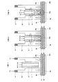
- FIG. 3A is a process diagram schematically showing an example of each process of friction stir spot welding by the friction stir spot welding apparatus shown in FIG. 1.
- FIG. 3B is a process diagram schematically showing an example of each process of friction stir spot welding by the friction stir spot welding apparatus shown in FIG. 1.
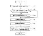
- FIG. 4 is a flowchart showing an example of the operation of the friction stir spot welding device according to the first embodiment when continuous welding is performed.
- FIG. 1 is a schematic diagram showing a schematic configuration of the friction stir spot welding device according to the first embodiment.
- FIG. 2 is a block diagram schematically showing a control configuration of the friction stir spot welding device shown in FIG.
- FIG. 3A is a process diagram schematically showing an example of each process of friction stir spot welding by the friction stir spot welding apparatus shown in FIG. 1.
- FIG. 5 is a graph showing the relationship between the tool temperature when the continuous joining test is performed without changing the pressing force, and the amount of press-fitting of the shoulder member and the amount of recess in the joint.
- FIG. 6 is a graph showing the relationship between the tool temperature when the pressing force is changed and the continuous joining test is performed, the amount of press-fitting of the shoulder member, and the amount of depression of the joining portion.
- FIG. 7 is a flowchart showing an example of the operation of the friction stir spot welding device according to the second embodiment when continuous welding is performed.
- FIG. 8 is a flowchart showing an example of the operation of the friction stir spot welding device according to the third embodiment when continuous welding is performed.
- FIG. 9 is a flowchart showing an example of the operation of the friction stir spot welding device according to the fourth embodiment when continuous welding is performed.
- FIG. 10 is a flowchart illustrating an example of the operation of the friction stir spot welding device according to the fifth embodiment when continuous welding is performed.
- FIG. 11 is a flowchart showing an example of the operation of the friction stir spot welding device according to the sixth embodiment when continuous welding is performed.
- FIG. 12 is a flowchart illustrating an example of the operation of the friction stir spot welding device according to the seventh embodiment when continuous welding is performed.
- the inventors of the present invention have proposed that the tip of the clamp member when two aluminum alloy 2024 clad-T3 materials (plate thickness 0.8 mm) are joined in succession by various cooling methods.
- a defect in appearance quality (mainly a dent in the joint) occurred.
- the inventors of the present invention overlapped two aluminum alloys A7075C-T6 (plate thickness 1.27 mm), and set the waiting time from the end of joining of one joint to the start of joining of the next joint as 1 second.
- a test (hereinafter referred to as a continuous bonding test) for continuously bonding 40 joints was performed.
- the pressing force with which the pin member and the shoulder member press the object to be joined is performed at the same predetermined pressure at any joint.
- the tool temperature at the end of each joint (the temperature of the outer peripheral surface near the tip of the clamp member) is detected by a temperature detector, and the amount of press-fitting of the shoulder member from the surface of the object to be joined (the object to be joined) The depth from the surface) was monitored. And the amount of dents from the surface of the object to be bonded (depth from the surface of the object to be bonded) in each bonded part after the end of bonding was measured. The result is shown in FIG.
- the diamond shape ( ⁇ ) indicates the tool temperature
- the square shape ( ⁇ ) indicates the amount of increase in the amount of press-fitting of the shoulder member from the first striking point (the value when most pressed)
- the triangle ( ⁇ ) indicates the joining The amount of dents from the surface of the object to be joined in the part is shown. Note that the 40th joint may be referred to as the 40th spot.
- the appearance quality (mainly the dent of the joint portion) did not occur even after repeated joining.
- these temperature threshold values are not uniformly defined because they vary depending on the material to be joined, the plate thickness, and the material of the shoulder member.
- the present inventors such as appearance quality in the case of continuous joining, to perform the next joining while the heat generated by friction is accumulated in the pin member and the shoulder member, Compared to single welding, the time until the metal material is softened is faster, and as a result, continuous welding is performed at the same time, the same rotational speed, or the same pressing force as single bonding.
- it considers that it is a cause (factor) that the material which softens increases and the material has flowed to the outer side (clamp member side) etc. of the shoulder member.
- the temperature of the tool pin member or shoulder member
- the pressing force of the tool corresponding to the temperature is detected.
- the problem can be solved by reducing at least one of the pressing force for pressing the workpiece, the number of rotations of the tool, and the operation time of the tool.
- the friction stir spot welding device is a friction stir spot welding device that softens a workpiece with frictional heat and joins the workpieces by stirring.
- the friction stir spot joining device is formed in a columnar shape and rotates around an axis.
- a tool configured to be capable of moving back and forth in a direction along the axis, a temperature detector for detecting the temperature of the tool, and a workpiece to be joined when joining the workpiece continuously. Compare the temperature of the tool detected by the temperature detector between the end of the joining process and the start of the next joining process to the specified reference temperature, and the tool in the next joining process presses the workpiece.
- a controller configured to set a pressing force to perform.
- FIG. 1 is a schematic diagram showing a schematic configuration of the friction stir spot welding device according to the first embodiment.
- the up-down direction in a figure is represented as the up-down direction in a friction stir spot welding apparatus.
- the friction stir spot welding device 50 includes a pin member 11, a shoulder member 12, a tool fixing device 52, a tool driver 53, a clamp member 54, a backing support portion 55, A backing member 56 and a rotation driver 57 are provided.
- the pin member 11 and the shoulder member 12 are supported by a tool fixing device 52, and are driven to advance and retract in the vertical direction by a tool driver 53.
- the pin member 11, the shoulder member 12, the tool fixing device 52, the tool driver 53, and the clamp member 54 are provided on an upper portion of a backing support portion 55 configured by a C-type gun (C-type frame).
- a backing member 56 is provided below the backing support portion 55.
- the pin member 11 and the shoulder member 12 and the backing member 56 are attached to the backing support portion 55 at positions facing each other.
- a workpiece 60 is disposed between the pin member 11 and the shoulder member 12 and the backing member 56.
- the tool fixing device 52 includes a rotating tool fixing device 521 and a clamp fixing device 522
- the tool driving device 53 includes a pin driving device 531, a shoulder driving device 532, and a clamping driving device 41.
- the clamp member 54 is fixed to the clamp fixture 522 via the clamp driver 41.
- the clamp driver 41 is configured by a spring.
- the pin member 11 is formed in a substantially cylindrical shape or a substantially cylindrical shape, and is supported by a rotary tool fixing device 521, although not shown in detail in FIG. Further, the pin member 11 is rotated around the axis line Xr (rotation axis) coinciding with the axis of the pin member 11 by the rotation driver 57, and the arrow P1 direction, that is, the axis line Xr direction (FIG. 1) by the pin driver 531. Then, it is configured to move forward and backward along the vertical direction.
- axis line Xr rotation axis
- the shoulder member 12 is formed in a substantially cylindrical shape having a hollow, and is supported by a rotary tool fixing device 521.
- a pin member 11 is inserted into the hollow of the shoulder member 12.
- the shoulder member 12 is disposed so as to surround the outer peripheral surface of the pin member 11.
- the shoulder member 12 is configured to rotate around the same axis line Xr as the pin member 11 by the rotation driver 57, and to be moved forward and backward along the arrow P2 direction, that is, the axis line Xr direction by the shoulder driver 532. Yes.
- the pin member 11 and the shoulder member 12 are both supported by the same rotary tool fixing device 521 in the present embodiment, and both rotate integrally around the axis Xr by the rotation driver 57. Further, the pin member 11 and the shoulder member 12 are configured to be movable back and forth along the axis Xr direction by a pin driver 531 and a shoulder driver 532, respectively. In the first embodiment, the pin member 11 can move forward and backward independently, and can also move forward and backward with the forward and backward movement of the shoulder member 12, but the pin member 11 and the shoulder member 12 are Each may be configured to be able to move forward and backward independently.
- the clamp member 54 is formed in a cylindrical shape having a hollow, like the shoulder member 12, and is provided so that its axis coincides with the axis Xr.
- the shoulder member 12 is inserted into the hollow of the clamp member 54.
- each of the clamp member 54, the shoulder member 12, and the pin member 11 has a coaxial core-like nested structure.
- the clamp member 54 is configured to press the workpiece 60 from one surface (surface). As described above, the clamp member 54 is supported by the clamp fixing device 522 via the clamp driver 41 in the first embodiment. The clamp driver 41 is configured to urge the clamp member 54 toward the backing member 56 side.
- the clamp driver 41 is configured by a spring in the first embodiment, but is not limited to this.
- the clamp driver 41 only needs to be configured to apply an urging force or a pressurizing force to the clamp member 54.
- a mechanism using a gas pressure, a hydraulic pressure, a servo motor, or the like can be suitably used.
- Rotating tool fixing device 521 is supported on clamp fixing device 522 via rotation driving device 57.
- the clamp member 54 (including the clamp driver 41 and the clamp fixture 522) is configured to be advanced and retracted in the direction of the arrow P3 (the same direction as the arrows P1 and P2) by the shoulder driver 532.
- the clamp driver 41 and the shoulder driver 532 constitute a clamp member driver.
- the clamp member driver may be configured by a driver that drives the clamp member 54 so that the clamp member 54 can move forward and backward independently of the shoulder driver 532.
- the pin member 11, the shoulder member 12, and the clamp member 54 are each provided with a tip portion 11a, a tip portion 12a, and a tip portion 54a. Further, the pin member 11, the shoulder member 12, and the clamp member 54 are moved forward and backward by the tool driver 53, so that the tip portion 11 a, the tip portion 12 a, and the tip portion 54 a are respectively placed on the surface of the workpiece 60. Abut.
- the backing member 56 is configured to be supported by a flat surface (support surface 56a) so as to contact the back surface of the flat plate-like object 60.
- the configuration of the backing member 56 is not particularly limited as long as the backing member 56 can appropriately support the workpiece 60 so that the friction stir spot welding can be performed.
- the backing member 56 may be configured such that, for example, a backing member 56 having a plurality of types of shapes is separately prepared and can be removed and replaced from the backing support portion 55 according to the type of the object to be joined 60. Good.
- the pin member 11, the shoulder member 12, the tool fixing device 52, the tool driving device 53, the clamp member 54, the backing support portion 55, and the rotation driving device 57 in the first embodiment have been described above. It is not limited to the configuration, and a configuration widely known in the field of friction stir welding can be suitably used.
- the pin driver 531 and the shoulder driver 532 constituting the tool driver 53 are each composed of a motor and a gear mechanism that are well-known in the field of friction stir welding. It is not limited.
- the configuration including the clamp member 54 is adopted.
- the configuration is not limited thereto, and a configuration not including the clamp member 54 may be employed.
- the clamp member 54 may be configured to be detachable from the backing support portion 55 as necessary.
- the backing support portion 55 is configured by a C-type gun, but is not limited thereto.
- the backing support portion 55 is configured to support the pin member 11 and the shoulder member 12 so as to be capable of moving forward and backward and to support the backing member 56 at a position facing the pin member 11 and the shoulder member 12. May be.
- the friction stir spot welding device 50 employs a configuration that is disposed in a friction stir spot welding robot device (not shown). Specifically, the backing support portion 55 is attached to the tip of the arm of the robot apparatus. For this reason, it can be considered that the backing support portion 55 is also included in the friction stir spot welding robot apparatus.
- the specific configuration of the friction stir spot welding robot apparatus including the backing support portion 55 and the arm is not particularly limited, and a known configuration in the field of friction stir welding such as an articulated robot can be suitably used. .
- the friction stir spot welding device 50 (including the backing support portion 55) is not limited to a case where the friction stir spot welding device 50 is applied to a friction stir spot welding robot device.
- a friction stir spot welding robot device for example, an NC machine tool, a large C frame, And it can apply suitably also to well-known processing apparatuses, such as an auto riveter.
- the friction stir spot welding device 50 may adopt a configuration in which the workpiece 60 is hand-held as long as the friction stir spot welding can be stably performed on the workpiece 60. You may employ
- FIG. 2 is a block diagram schematically showing a control configuration of the friction stir spot welding device shown in FIG.
- the friction stir spot welding device 50 includes a controller 51, a temperature detector 21, a storage device 31, and an input device 32.
- the storage device 31 stores various data in a readable manner, and the storage device 31 includes a storage device such as a known memory or a hard disk.
- the storage device 31 does not have to be single, and may be configured as a plurality of storage devices (for example, a random access memory and a hard disk drive).
- the controller 51 or the like is configured by a microcomputer, at least a part of the storage unit 31 may be configured as an internal memory of the microcomputer or may be configured as an independent memory.
- the memory 31 stores data and may be able to read data from other than the controller 51 or may be able to write data from the controller 51 or the like. Not too long.
- the storage unit 31 stores a reference temperature, a pressing force of the tool (the pin member 11 and the shoulder member 12) at the reference temperature, and an arithmetic expression for adjusting the pressing force described later.
- the first reference temperature T1 that is an arbitrary temperature between 20 to 80 ° C. of the pin member 11, and the pressing force F1 of the tool at the first reference temperature T1 (for example, 3000 N to 8000 N).
- the pressing force F2 of the tool at the temperature T2 (for example, an arbitrary value included in the range of 500 to 2000 N) is stored.
- the first reference temperature T1, the second reference temperature T2, the pressing force F1, and the pressing force F2 can be obtained in advance through experiments or the like.
- the first reference temperature T1 may be an average value of the temperature of the pin member 11 after the object 60 is bonded in a state where the pin member 11 and / or the shoulder member 12 is sufficiently cooled.
- the second reference temperature T2 is the temperature of the pin member 11 when the temperature rise of the pin member 11 is moderated (for example, the tenth spot in the graph shown in FIG. 4) when the workpiece 60 is continuously joined. There may be.
- the pressing force F1 can be set as appropriate depending on the material of the workpiece 60 and the like.
- the pressing force F2 is a pressing force when a defect such as an appearance quality in the bonded portion at the tenth point does not occur when the workpiece 60 is continuously bonded (for example, ten points) with a predetermined pressing force. Also good.
- the input device 32 allows the controller 51 to input various parameters relating to the control of friction stir spot welding, other data, or a start command for friction stir spot welding, and the like. It consists of a known input device such as a switch group.
- a known input device such as a switch group.
- at least the joining condition of the article to be joined 60, for example, data such as the thickness and material of the article to be joined 60 can be input by the input device 32.
- the temperature detector 21 is configured to detect the temperature of the tool and output the detected temperature to the controller 51.
- the first embodiment is configured to detect the temperature of the tip end portion 11 a of the pin member 11 and output the detected temperature to the controller 51.
- various known temperature sensors can be used. For example, a radiation thermometer, a thermography, a thermocouple, or the like can be used.
- the temperature detector 21 directly detects the temperature of the tip portion 11a of the pin member 11, but indirectly detects the temperature of the tip portion 11a of the pin member 11.
- a form may be adopted.
- the temperature detector 21 may be configured to detect the temperature of the distal end portion 12 a of the shoulder member 12 or the distal end portion 54 a of the clamp member 54.
- thermocouple when used as the temperature detector 21, a form attached to the outer peripheral surface in the vicinity of the front end portion 12 a of the shoulder member 12 may be adopted, or attached to the outer peripheral surface in the vicinity of the front end portion 54 a of the clamp member 54. A form may be adopted.
- the controller 51 is configured to control each member (each device) constituting the friction stir spot welding device 50. Specifically, the controller 51 controls the pin driver 531 and the shoulder driver 532 that constitute the tool driver 53, and the rotation driver 57.
- the controller 51 can control the pressing force that presses the workpiece 60 to be joined, the number of rotations of the tool, and the operation time of the tool.
- the controller 51 compares the pressing force with which the tool presses the workpiece 60 with the pressing force at the reference temperature as the temperature of the tip portion 11a of the pin member 11 detected by the temperature detector 21 is higher. Reduce.
- the specific configuration of the controller 51 is not particularly limited.
- the controller 51 is constituted by a CPU of a microcomputer, and the CPU performs predetermined control stored in the storage device 31. By reading out the program and executing it, it is configured to perform calculations related to the operation of the tool driver 53 and the rotary driver 57.
- the controller 51 is not only configured as a single controller, but also configured as a controller group in which a plurality of controllers cooperate to execute control of the friction stir spot welding device 50. It does not matter.
- the controller 51 starts temperature data detected by the temperature detector 21 when starting to join the workpiece 60, and the first reference temperature T1 and the second reference temperature T2 stored in the storage device 31. Based on the pressing force F1 of the tool at the first reference temperature T1, the pressing force F2 of the tool at the second reference temperature T2, and the calculation expression for adjusting the pressing force, the tool presses the workpiece 60. The pressure is set (calculated).
- the controller 51 has a pressing force Fn at which the tool presses the workpiece 60 at the temperature Tn when the temperature of the tip 11a of the pin member 11 detected by the temperature detector 21 is Tn. Is set by the following equation (1).
- the temperature detector 21 detects the temperature of the pin member 11 when starting the bonding of the workpiece 60.
- the present invention is not limited to this. For example, after the joining process with respect to the article to be joined 60 is finished (from when the pin member 11, the shoulder member 12, and the clamp member 54 are separated from the article to be joined 60) until the next joining process is started ( Next, a mode in which the temperature detector 21 detects the temperature of the pin member 11 at an arbitrary timing (until the pin member 11, the shoulder member 12, and the clamp member 54 come into contact with the workpiece 60) is adopted. May be.
- the arithmetic expression (formula (1)) for adjusting the pressing force is shown as a linear function, but is not limited to this, and may be shown as a high-order function, an exponential function, or You may show by a logarithmic function.
- the controller 51 controls the tool driver 53 and the rotation driver 57 to operate the pin member 11 and the shoulder member 12 while pressing the workpiece 60 with the pressing force Fn set by the tool. Specifically, the controller 51 sets Ap as the cross-sectional area of the tip surface of the pin member 11, As as the cross-sectional area of the tip surface of the shoulder member 12, Pp as the press-fit depth of the pin member 11, and press-fit of the shoulder member 12. When the depth is Ps, the tool driver 53 and the rotation driver 57 are controlled so as to reduce the absolute value of the tool average position Tx defined by the equation (2).
- FIG. 3A and 3B are process diagrams schematically showing an example of each process of friction stir spot welding by the friction stir spot welding apparatus shown in FIG. 3A and 3B, a part of the friction stir spot welding device is omitted, the arrow r indicates the rotation direction of the pin member 11 and the shoulder member 12, and the block arrow F is on the metal plates 61 and 62. Indicates the direction of the applied force.
- the controller 51 drives the tool driver 53 to bring the clamp member 54 closer to the workpiece 60 (metal plates 61 and 62), and the tip 54a of the clamp member 54 (FIGS. 3A and 3B show (Not shown) is brought into contact with the surface 60c of the workpiece 60 (see step (1) in FIG. 3A).
- the metal plates 61 and 62 are sandwiched between the clamp member 54 and the backing member 56, and the clamp member 41 is urged toward the surface 60 c side of the workpiece 60 due to contraction of the clamp driver 41, and the clamping force is increased. appear.
- the controller 51 drives the rotary driver 57 to drive the tool driver 53 in a state where the pin member 11 and the shoulder member 12 are rotated, thereby joining the pin member 11 and the shoulder member 12 together.
- the object 60 is made to approach and the front end part 11a of the pin member 11 and the front end part 12a of the shoulder member 12 are brought into contact with the surface 60c of the article to be joined 60 while rotating.
- the controller 51 presses the workpiece 60 with a predetermined pressing force (for example, a predetermined value included in the range of 3000 N to 8000 N) for the pin member 11, the shoulder member 12, and the clamp member 54.
- a predetermined pressing force for example, a predetermined value included in the range of 3000 N to 8000 N
- the tool driver 53 is controlled.
- the controller 51 controls the pin driver 531 and / or the shoulder driver 532 (see FIG. 1) to retract the pin member 11 from the surface 60c of the workpiece 60, thereby causing the shoulder member 12 to move backward. It further enters (press-fits) from the surface 60c of the workpiece 60 (see step (3) in FIG. 3A). At this time, the softened portion of the metal material extends from the upper metal plate 61 to the lower metal plate 62, and the region of the plastic flow portion 60a increases.
- the controller 51 controls the pin driver 531 to gradually enter (press-fit) the retracted pin member 11 into the metal plate 61. Along with this, the shoulder member 12 moves backward from the metal plate 61 (see step (4) in FIG. 3B). In addition, the said process (4) does not need to be performed, when the surface 60c of the metal plate 61 is fully shaped by the process (5) mentioned later.
- the controller 51 controls the tool driver 53 so as to reduce the absolute value of the tool average position Tx as described above. Since specific control for reducing the absolute value of the tool average position Tx is disclosed in detail in Patent Document 1, the description thereof is omitted here.
- the controller 51 controls the pin driver 531 to gradually enter the pin member 11 when the process (3) shifts to the process (5).
- the controller 51 controls the pin driver 531 to gradually draw the pin member 11.
- the pressure applied by the tip is maintained (the arrow F in step (3) in FIG. 3A and the step (4 in FIG. 3B)). ) (See arrow F).
- the controller 51 controls the tool driver 53 so that the tip end portion 11a of the pin member 11 and the tip end portion 12a of the shoulder member 12 are adjusted to such an extent that there is almost no step between them (they are flush).
- the surface 60c of the to-be-joined object 60 is shape
- the controller 51 controls the tool driver 53 to separate the pin member 11, the shoulder member 12, and the clamp member 54 from the workpiece 60, and then controls the rotation driver 57 to control the pin member. 11 and the shoulder member 12 are stopped from rotating, and a series of friction stir spot joining (joining process of the workpiece 60) is terminated (see process (6) in FIG. 3B). Accordingly, the rotation (and pressing) due to the contact between the pin member 11 and the shoulder member 12 is not applied to the metal plates 61 and 62, so that the plastic flow is stopped in the plastic flow portion 60 a extending over both the metal plates 61 and 62. And it becomes the junction part 60b. In this way, the two metal plates 61 and 62 are connected (joined) by the joint portion 60b.
- FIG. 4 is a flowchart showing an example of the operation of the friction stir spot welding device according to the first embodiment when continuous welding is performed.
- step S101 the controller 51 acquires the temperature Tn of the pin member 11 detected by the temperature detector 21 (step S101).
- the controller 51 determines whether or not the temperature Tn acquired in step S101 is higher than the first reference temperature T1 stored in the storage device 31 (step S102).
- step S101 When the temperature Tn acquired in step S101 is higher than the first reference temperature T1 (Yes in step S102), the controller 51 sets the pressing force of the tool that presses the workpiece 60 (step S103). Specifically, as described above, the controller 51 sets the pressing force by substituting the temperature Tn acquired in Step S101 into Equation (1), and proceeds to Step S104. On the other hand, when the temperature Tn acquired in step S101 is equal to or lower than the first reference temperature T1 (No in step S102), the controller 51 does not set the pressing force and proceeds to step S104.
- step S104 the controller 51 drives the tool driver 53 to move the pin member 11, the shoulder member 12, and the clamp member 54 so as to approach the workpiece 60 (the metal plate 61, the metal plate 62). .
- the controller 51 drives the tool driver 53 so that the tool presses the workpiece 60 with the set pressing force.
- the controller 51 causes the tool to be joined with the pressing force F1 at the first reference temperature T1.
- the tool driver 53 is driven so as to press the object 60.
- the controller 51 rotates the pin member 11 and the shoulder member 12 by driving the rotation driver 57 at a predetermined rotation speed set in advance (step S105). Accordingly, the pin member 11, the shoulder member 12, and the clamp member 54 move so as to approach the workpiece 60 while the pin member 11 and the shoulder member 12 rotate.
- the controller 51 employs a form in which the rotary driver 57 is driven after the tool driver 53 is driven.
- the present invention is not limited to this.
- the controller 51 may employ a mode in which the tool driver 53 is driven after the rotation driver 57 is driven.
- the controller 51 drives the tool driver 53 so that the rotation driver 57 is driven after the pin member 11, the shoulder member 12, and the clamp member 54 contact the workpiece 60. May be.
- the controller 51 controls the tool driver 53 so that the pin member 11, the shoulder member 12, and the clamp member 54 are separated from the workpiece 60 when the joining process of the workpiece 60 is finished. Return to the start of the flow and perform the next bond.
- Example 1 Next, the Example which performed the continuous joining of the to-be-joined object 60 using the friction stir spot welding apparatus 50 which concerns on this Embodiment 1 is demonstrated, referring FIG.
- the pin member 11 and the shoulder member 12 are in accordance with the temperature of the tip portion 12a of the pin member 11.
- the pressing force for pressing the object to be bonded 60 the appearance quality and the like of the bonded portion of the object to be bonded 60 can be sufficiently secured, and good bonding quality can be realized.
- the friction stir spot welding device is a friction stir spot welding device that softens the workpieces by friction heat and joins them by stirring.
- the friction stir spot joining device is formed in a columnar shape and rotates around an axis.
- a tool configured to be capable of moving back and forth in a direction along the axis, a temperature detector for detecting the temperature of the tool, and a workpiece to be joined when joining the workpiece continuously.
- the temperature of the tool detected by the temperature detector between the end of the joining process and the start of the next joining process is compared with a predetermined reference temperature, and the number of rotations of the tool in the next joining process is set.
- a controller configured as described above.
- the friction stir spot welding apparatus since the friction stir spot welding apparatus according to the second embodiment is configured in the same manner as the friction stir spot welding apparatus according to the first embodiment, description of the configuration is omitted.
- FIG. 7 is a flowchart showing an example of the operation of the friction stir spot welding device according to the second embodiment when continuous welding is performed.
- step S103A is executed instead of step S103.
- step S101 when the temperature Tn acquired in step S101 is higher than the first reference temperature T1 (Yes in step S102), the controller 51 sets the number of rotations of the tool (step S103A), and proceeds to step S104. move on. At this time, the controller 51 may set the rotational speed of the tool to be smaller than the rotational speed of the tool at the first reference temperature T1. Further, the controller 51 may further reduce the number of rotations of the tool in proportion to the temperature increase of the pin member 11.
- step S101 when the temperature Tn acquired in step S101 is equal to or lower than the first reference temperature T1 (No in step S102), the controller 51 does not set the rotation speed and proceeds to step S104.
- step S105 when the rotation number is set in step S103A, the controller 51 drives the rotation driver 57 so that the tool rotates at the set rotation number. Further, when the rotation speed is not set in step S103A (that is, when the temperature Tn is equal to or lower than the first reference temperature T1), the controller 51 causes the tool to rotate at the rotation speed at the first reference temperature T1. Then, the rotation driver 57 is driven.
- the controller compares the temperature of the tool detected by the temperature detector with the reference temperature, and the pressing force by which the tool presses the workpiece and the rotation of the tool.
- the mode which sets a number is illustrated.
- the friction stir spot welding apparatus according to the third embodiment is configured in the same manner as the friction stir spot welding apparatus according to the first embodiment, description of the configuration is omitted.
- FIG. 8 is a flowchart showing an example of the operation of the friction stir spot welding device according to the third embodiment when continuous welding is performed.
- step S103B is executed instead of step S103.
- step S101 when the temperature Tn acquired in step S101 is higher than the first reference temperature T1 (Yes in step S102), the controller 51 presses the tool pressing the workpiece 60 and the rotation of the tool.
- the number is set (step S103B), and the process proceeds to step S104.
- the controller 51 sets the pressing force to be smaller than the pressing force of the tool at the first reference temperature T1, and the rotation number becomes smaller than the rotation number of the tool at the first reference temperature T1.
- the controller 51 may be set so that the pressing force is larger than the pressing force of the tool set in the first embodiment as long as it is lower than the pressing force of the tool at the first reference temperature T1. Further, the controller 51 may be set so that the rotational speed is higher than the rotational speed of the tool set in the second embodiment as long as it is lower than the rotational speed of the tool at the first reference temperature T1.
- the friction stir spot welding device is a friction stir spot welding device that softens the workpieces by friction heat and joins them by stirring.
- the friction stir spot welding device is formed in a columnar shape and rotates around an axis.
- a tool configured to be capable of moving back and forth in a direction along the axis, a temperature detector for detecting the temperature of the tool, and a workpiece to be joined when joining the workpiece continuously.
- the tool operating time in the next joining process is set by comparing the temperature of the tool detected by the temperature detector between the end of the joining process and the start of the next joining process with a predetermined reference temperature.
- a controller configured as described above.
- the friction stir spot welding apparatus since the friction stir spot welding apparatus according to the fourth embodiment is configured in the same manner as the friction stir spot welding apparatus according to the first embodiment, description of the configuration is omitted.
- FIG. 9 is a flowchart showing an example of the operation of the friction stir spot welding device according to the fourth embodiment when continuous welding is performed.
- step S103C is executed instead of step S103.
- step S101 when the temperature Tn acquired in step S101 is higher than the first reference temperature T1 (Yes in step S102), the controller 51 sets the operation time of the tool (step S103C), and proceeds to step S104. move on. At this time, the controller 51 may set the operation time to be shorter than the operation time of the tool at the first reference temperature T1. Further, the controller 51 may shorten the operation time of the tool in proportion to the temperature increase of the pin member 11.
- the operation time of the tool set in step S103C is that the tool is moved to a predetermined position where the workpiece 60 is joined, and then the tool is moved by the pin driver 531 and / or the shoulder driver 532.
- the time from when the tool is moved in the thickness direction until the tool is separated from the workpiece 60 may be used.
- the operation time of the tool set in step S103C may be a time from when the tool is rotated in a state of being in contact with the surface 60c of the workpiece 60 until the tool is separated from the workpiece 60. .
- the controller 51 sets the operation time of the tool to rotate the tool in contact with the surface 60c of the workpiece 60 (time for preheating the workpiece 60; step of FIG. 3A). (2)) may be set.
- the controller 51 moves the tool in the thickness direction of the workpiece 60 (vertical direction in FIG. 1) after preliminary overheating as the operation time of the tool (step (3) in FIG. 3A and / or FIG. 3B).
- the time for step (4)) may be set.
- the controller 51 sets a time for moving the pin member 11 or the shoulder member 12 in the direction in which the pin member 11 or the shoulder member 12 is press-fitted from the surface of the workpiece 60 into the inside (downward direction in FIG. 1).
- the time for moving the pin member 11 or the shoulder member 12 in the direction away from the surface of the workpiece 60 may be set.
- step S101 when the temperature Tn acquired in step S101 is equal to or lower than the first reference temperature T1 (No in step S102), the controller 51 proceeds to step S104 without setting the operation time of the tool.
- step S105 when the operation time of the tool is set in step S103C, the controller 51 sets the tool driver 53 and / or the rotation driver 57 so that the tool operates in the set operation time. Drive. Further, when the operation time of the tool is not set in Step S103C (that is, when the temperature Tn is equal to or lower than the first reference temperature T1), the controller 51 operates the tool at the operation time at the first reference temperature T1. As described above, the tool driver 53 and / or the rotary driver 57 are driven.
- the form which compares the temperature Tn and the 1st reference temperature and sets the operation time of a tool was employ
- adopted it is not limited to this.
- a mode may be adopted in which the temperature Tn is compared with the first reference temperature, and the speed at which the tool is moved in the thickness direction of the workpiece 60 is set by the pin driver 531 and / or the shoulder driver 532. Good.
- the controller 51 preheats the workpiece 60 and then moves the tool in the thickness direction of the workpiece 60 (vertical direction in FIG. 1) (step (3) in FIG. 3A and FIG.
- the speed of step (4) in 3B is set.
- the controller 51 may set the speed at which the pin member 11 or the shoulder member 12 is press-fitted from the surface of the workpiece 60 and moved to a predetermined position (predetermined depth).
- the speed of moving to a predetermined position (predetermined height) away from the surface of the workpiece 60 may be set, and the pin member 11 or the shoulder member 12 positioned at a predetermined depth
- the speed at which the pin member 11 or the shoulder member 12 positioned at a predetermined height is moved to a predetermined depth may be set.
- the controller 51 may set the speed to be higher than the speed at which the tool is moved at the first reference temperature T1. Further, the controller 51 may increase the speed at which the tool is moved in proportion to the temperature increase of the pin member 11.
- the controller compares the temperature of the tool detected by the temperature detector with the reference temperature, and the pressing force by which the tool presses the workpiece and the operation of the tool.
- the mode which sets time is illustrated.
- the friction stir spot welding apparatus according to the fifth embodiment is configured in the same manner as the friction stir spot welding apparatus according to the first embodiment, description of the configuration is omitted.
- FIG. 10 is a flowchart illustrating an example of the operation of the friction stir spot welding device according to the fifth embodiment when continuous welding is performed.
- step S103D is executed instead of step S103.
- step S101 when the temperature Tn acquired in step S101 is higher than the first reference temperature T1 (Yes in step S102), the controller 51 presses the tool pressing the workpiece 60 and the operation of the tool. Time is set (step S103D), and the process proceeds to step S104. At this time, the controller 51 sets the pressing force to be smaller than the pressing force of the tool at the first reference temperature T1, so that the operating time is shorter than the operating time of the tool at the first reference temperature T1. Set to.
- the controller 51 may be set so that the pressing force is larger than the pressing force of the tool set in the first embodiment as long as it is lower than the pressing force of the tool at the first reference temperature T1. Further, the controller 51 may be set so that the operation time is longer than the operation time of the tool set in the fourth embodiment as long as it is shorter than the operation time of the tool at the first reference temperature T1.
- the controller compares the tool temperature detected by the temperature detector with the reference temperature, and sets the rotation speed of the tool and the operation time of the tool. This is just an example.
- the friction stir spot welding apparatus according to the sixth embodiment is configured in the same manner as the friction stir spot welding apparatus according to the first embodiment, description of the configuration is omitted.
- FIG. 11 is a flowchart showing an example of the operation of the friction stir spot welding device according to the sixth embodiment when continuous welding is performed.
- step S103E is executed instead of step S103.
- step S101 when the temperature Tn acquired in step S101 is higher than the first reference temperature T1 (Yes in step S102), the controller 51 sets the rotation speed of the tool and the operation time of the tool (step S103E). ), The process proceeds to step S104. At this time, the controller 51 sets the rotational speed of the tool to be smaller than the rotational speed of the tool at the first reference temperature T1, so that the operating time is shorter than the operating time of the tool at the first reference temperature T1. Set to.
- the controller 51 may be set so that the rotational speed of the tool is higher than the rotational speed of the tool set in the second embodiment as long as it is lower than the rotational speed of the tool at the first reference temperature T1. Further, the controller 51 may be set so that the operation time is longer than the operation time of the tool set in the fourth embodiment as long as it is shorter than the operation time of the tool at the first reference temperature T1.
- the controller compares the temperature of the tool detected by the temperature detector with the reference temperature, the pressing force by which the tool presses the workpiece, and the rotation of the tool It illustrates the manner of setting the number and the operating time of the tool.
- the friction stir spot welding apparatus according to the seventh embodiment is configured in the same manner as the friction stir spot welding apparatus according to the first embodiment, description of the configuration is omitted.
- FIG. 12 is a flowchart illustrating an example of the operation of the friction stir spot welding device according to the seventh embodiment when continuous welding is performed.
- step S103F is executed instead of step S103.
- step S101 when the temperature Tn acquired in step S101 is higher than the first reference temperature T1 (Yes in step S102), the controller 51 presses the tool 60 against the workpiece 60 and rotates the tool.
- the number and the operation time of the tool are set (step S103F), and the process proceeds to step S104.
- the controller 51 sets the pressing force to be smaller than the pressing force of the tool at the first reference temperature T1, and the rotation number becomes smaller than the rotation number of the tool at the first reference temperature T1.
- the operation time is set to be shorter than the operation time of the tool at the first reference temperature T1.
- the controller 51 may be set so that the pressing force is larger than the pressing force of the tool set in the first embodiment as long as it is lower than the pressing force of the tool at the first reference temperature T1. Further, the controller 51 may be set so that the rotational speed is higher than the rotational speed of the tool set in the second embodiment as long as it is lower than the rotational speed of the tool at the first reference temperature T1. Further, the controller 51 may be set so that the operation time is longer than the operation time of the tool set in the fourth embodiment as long as it is shorter than the operation time of the tool at the first reference temperature T1.
- the friction stir spot welding device 50 is exemplified as a double-acting friction stir spot welding device.
- the aspect which is a single-acting friction stir spot welding apparatus may be sufficient as a joining apparatus.
- the friction stir spot welding apparatus and the friction stir spot joining method of the present invention are useful because they can realize good joint quality even when continuously joined.
Landscapes
- Engineering & Computer Science (AREA)
- Mechanical Engineering (AREA)
- Pressure Welding/Diffusion-Bonding (AREA)
Abstract
本発明に係る摩擦攪拌点接合装置は、被接合物(60)を摩擦熱で軟化させ、攪拌することにより接合する摩擦攪拌点接合装置であって、円柱状に形成され、軸線周りの回転と該軸線に沿った方向への進退移動とが可能なように構成されているツールと、被接合物(60)の接合工程を開始するときに、ツールの温度を検出する温度検出器(21)と、温度検出器(21)が検出したツールの温度と基準温度とを比較して、ツールが被接合物(60)を押圧する押圧力を設定するように構成されている制御器(51)と、を備える。
Description
本発明は、摩擦攪拌点接合装置及び摩擦攪拌点接合方法に関する。
自動車、鉄道車両、航空機等の輸送機器においては、金属材料を連結するときには、抵抗スポット溶接又はリベット接合が用いられていた。しかしながら、近年では、摩擦熱を利用して金属材料を接合する方法(摩擦攪拌点接合方法)が注目されている(例えば、特許文献1参照)。
特許文献1に開示されている摩擦攪拌点接合方法では、略円柱状のピン部材と、該ピン部材を内挿するための中空を有する略円筒状のショルダ部材と、が、被接合物を接合するために用いられていて、以下に示すように、ピン部材とショルダ部材(回転工具;ツール)を作動(駆動)させる工具駆動部を制御している。
すなわち、ピン部材の先端面の断面積をAp、ショルダ部材の先端面の断面積をAs、ピン部材が被接合物の表面から圧入したときの圧入深さをPp、ショルダ部材が被接合物の表面から圧入したときの圧入深さをPsとしたときに、Ap・Pp+As・Ps=Txで定義されるツール平均位置Txの絶対値を小さくするように、工具駆動部を制御している。
これにより、接合条件に応じて好適な精度で良好な接合品質を実現し得るとともに、内部空洞欠陥の発生を防止または抑制することができる。
ところで、摩擦攪拌点接合装置により被接合物の接合を行うときに、ツール(裏当てを含む)の状態が著しく変化した際、特に、連続して接合した場合に外観不良が生じ得る。本発明者等は、当該課題について鋭意検討したところ、ツール(裏当てを含む)が蓄熱しており、単発で接合される場合よりも、ツールから熱が加えられることによって、材料がクランプ部の外側にまで軟化してしまい、クランプ部の下側の材料自体も流動してしまい、クランプ部ごと接合部が陥没したり、逆にクランプ部が隆起してしまったりすることが判った。
本発明は、上記課題を解決するためになされたものであって、連続して摩擦攪拌点接合を行っても、良好な接合品質を実現し得る、摩擦攪拌点接合装置及び摩擦攪拌点接合方法を提供することを目的とする。
上記従来の課題を解決するために、本発明に係る摩擦攪拌点接合装置は、被接合物を摩擦熱で軟化させ、攪拌することにより接合する摩擦攪拌点接合装置であって、円柱状に形成され、軸線周りの回転と該軸線に沿った方向への進退移動とが可能なように構成されているツールと、前記ツールの温度を検出する温度検出器と、制御器と、を備え、前記制御器は、前記被接合物を連続して接合する場合に、前記被接合物に対する接合工程を終了してから次の接合工程を開始するまでの間に前記温度検出器が検出した前記ツールの温度と所定の基準温度とを比較して、次の接合工程における前記ツールが前記被接合物を押圧する押圧力を設定するように構成されている。
これにより、連続して接合を行っても、良好な接合品質を実現し得る。
また、本発明に係る摩擦攪拌点接合装置は、被接合物を摩擦熱で軟化させ、攪拌することにより接合する摩擦攪拌点接合装置であって、円柱状に形成され、軸線周りの回転と該軸線に沿った方向への進退移動とが可能なように構成されているツールと、前記ツールの温度を検出する温度検出器と、制御器と、を備え、前記制御器は、前記被接合物を連続して接合する場合に、前記被接合物に対する接合工程を終了してから次の接合工程を開始するまでの間に前記温度検出器が検出した前記ツールの温度と所定の基準温度とを比較して、次の接合工程における前記ツールの回転数を設定するように構成されている。
これにより、連続して接合を行っても、良好な接合品質を実現し得る。
また、本発明に係る摩擦攪拌点接合装置は、被接合物を摩擦熱で軟化させ、攪拌することにより接合する摩擦攪拌点接合装置であって、円柱状に形成され、軸線周りの回転と該軸線に沿った方向への進退移動とが可能なように構成されているツールと、前記ツールの温度を検出する温度検出器と、前記被接合物を連続して接合する場合に、前記被接合物に対する接合工程を終了してから次の接合工程を開始するまでの間に前記温度検出器が検出した前記ツールの温度と所定の基準温度とを比較して、次の接合工程における前記ツールの作動時間を設定するように構成されている制御器と、を備える。
これにより、連続して接合を行っても、良好な接合品質を実現し得る。
また、本発明に係る摩擦攪拌点接合方法は、被接合物を摩擦熱で軟化させ、攪拌することにより接合する摩擦攪拌点接合方法であって、前記被接合物を連続して接合する場合に、前記被接合物に対する接合工程を終了してから次の接合工程を開始するまでの間に、温度検出器により前記ツールの温度を検出する(A)と、前記(A)で前記温度検出器が検出した前記ツールの温度と基準温度とを比較して、次の接合工程における前記ツールが前記被接合物を押圧する押圧力を設定する(B)と、を備える。
これにより、連続して接合を行っても、良好な接合品質を実現し得る。
また、本発明に係る摩擦攪拌点接合方法は、被接合物を摩擦熱で軟化させ、攪拌することにより接合する摩擦攪拌点接合方法であって、前記被接合物を連続して接合する場合に、前記被接合物に対する接合工程を終了してから次の接合工程を開始するまでの間に、温度検出器により前記ツールの温度を検出する(A)と、前記(A)で前記温度検出器が検出した前記ツールの温度と基準温度とを比較して、次の接合工程における前記ツールの回転数を設定する(C)と、を備える。
これにより、連続して接合を行っても、良好な接合品質を実現し得る。
さらに、本発明に係る摩擦攪拌点接合方法は、被接合物を摩擦熱で軟化させ、攪拌することにより接合する摩擦攪拌点接合方法であって、前記被接合物を連続して接合する場合に、前記被接合物に対する接合工程を終了してから次の接合工程を開始するまでの間に、温度検出器により前記ツールの温度を検出する(A)と、前記(A)で前記温度検出器が検出した前記ツールの温度と基準温度とを比較して、次の接合工程における前記ツールの作動時間を設定する(D)と、を備える。
これにより、連続して接合を行っても、良好な接合品質を実現し得る。
本発明の上記目的、他の目的、特徴、及び利点は、添付図面参照の下、以下の好適な実施形態の詳細な説明から明らかにされる。
本発明に係る摩擦攪拌点接合装置及び摩擦攪拌点接合方法によれば、連続して接合を行っても、良好な接合品質を実現し得る。
本発明者等は、上記特許文献1に開示されている摩擦攪拌点接合方法を用いた場合でも、ピン部材及びショルダ部材(以下、ツールということもある)を充分に冷却せずに、連続して接合を行った場合には、塑性流動域がピン/ショルダの直下より広がり、被接合物の外観品質等が不充分になるという知見を得た。ここで、「連続して接合を行う」とは、ピン部材及び/又はショルダ部材が充分に冷却(例えば、空冷)せずに、次の接合を行うことをいい、例えば、接合を終了後、所定の時間(例えば、2秒)以内に次の接合を開始する場合、及び/又は、次の接合を開始するときに、ピン部材及びショルダ部材の温度が所定の温度以上である場合、といった高サイクルで施工することをいう。
具体的には、本発明者等は、種々の冷却方法で連続して、2枚のアルミニウム合金2024クラッド-T3材(板厚0.8mm)への接合を行った場合におけるクランプ部材の先端部近傍の外周面の温度を計測したところ、200℃以上の温度のときに外観品質(主に接合部の凹み)の不良が発生した。
また、本発明者等は、2枚のアルミニウム合金A7075C-T6(板厚1.27mm)を重ねて、ある接合部の接合終了から次の接合部の接合開始までの待機時間を1秒として、連続して40か所の接合部の接合を実行する試験(以下、連続接合試験という)を行った。なお、本連続接合試験においては、ピン部材及びショルダ部材が被接合物を押圧する押圧力は、どの接合部においても、同じ所定の圧力で行っている。
連続接合試験中、各接合部の終了時のツール温度(クランプ部材の先端部近傍の外周面の温度)を温度検出器で検出し、ショルダ部材の被接合物表面からの圧入量(被接合物表面からの深さ)をモニタリングした。そして、接合終了後の各接合部における被接合物表面からの凹み量(被接合物表面からの深さ)を測定した。その結果を図5に示す。
図5では、菱形(◆)はツール温度を示し、四角(■)はショルダ部材の圧入量の1打点目からの増加量(最も圧入されたときの値)を示し、三角(▲)は接合部における被接合物表面からの凹み量を示す。なお、40か所目の接合を40打点目ということもある。
図5に示すように、ツール温度が上昇すると、ショルダ部材の圧入量及び接合部における被接合物表面からの凹み量ともに増加し、外観品質の不良が発生することとなる。また、10打点目までは、ツール温度が急激に上昇するが、10打点目以降は、ツール温度の上昇がなだらかになることがわかった。
一方、ショルダ部材の温度が20~60℃以下の温度まで冷却された条件では、繰り返して接合をしても、外観品質(主に接合部の凹み)の不良が発生しなかった。なお、これらの温度の閾値は、被接合材料及び板厚、並びにショルダ部材の材質により異なるので、一律に定義されるものではないことは言うまでもない。
そして、本発明者等は、連続して接合を行った場合における外観品質等の不良発生は、ピン部材及びショルダ部材に摩擦により発生した熱が蓄積されたまま、次の接合を実行するため、単発で接合を実行する場合に比して、より金属材料が軟化されるまでの時間が早くなり、その結果、単発の接合と同じ時間、同じ回転速度、又は同じ押圧力で連続して接合を行う場合、軟化する材料が多くなり、材料がショルダ部材の外側(クランプ部材側)等に流れてしまったことが原因(要因)であると考察している。
そこで、連続して被接合物を接合する場合に、次の接合を開始するまでの間に、ツール(ピン部材又はショルダ部材)の温度を検出し、当該温度に対応して、ツールの押圧力、ツールの回転数(回転速度)、及びツールの作動時間のうち、少なくとも1のパラメータを設定することにより、軟化材料の流出を防止することができ、連続して接合を行っても、良好な接合品質を実現し得ることを見出し、本発明を想到した。
すなわち、被接合物に対する接合工程を終了してから、次の接合工程を開始するまでの間に、温度検出器が検出したツールの温度が、第1基準温度よりも高い場合には、ツールが被接合物を押圧する押圧力、ツールの回転数、及びツールの作動時間のうち、少なくとも1のパラメータを低減させることで、上記課題(要因)を解決することができることを見出した。
以下、本発明の好ましい実施の形態を、図面を参照しながら説明する。なお、以下では全ての図を通じて同一又は相当する要素には同一の参照符号を付して、その重複する説明を省略する。また、全ての図面において、本発明を説明するために必要となる構成要素を抜粋して図示しており、その他の構成要素については図示を省略している場合がある。さらに、本発明は以下の実施の形態に限定されない。
(実施の形態1)
本実施の形態1に係る摩擦攪拌点接合装置は、被接合物を摩擦熱で軟化させ、攪拌することにより接合する摩擦攪拌点接合装置であって、円柱状に形成され、軸線周りの回転と該軸線に沿った方向への進退移動とが可能なように構成されているツールと、ツールの温度を検出する温度検出器と、被接合物を連続して接合する場合に、被接合物に対する接合工程を終了してから次の接合工程を開始するまでの間に温度検出器が検出したツールの温度と所定の基準温度とを比較して、次の接合工程におけるツールが被接合物を押圧する押圧力を設定するように構成されている制御器と、を備える態様を例示するものである。
本実施の形態1に係る摩擦攪拌点接合装置は、被接合物を摩擦熱で軟化させ、攪拌することにより接合する摩擦攪拌点接合装置であって、円柱状に形成され、軸線周りの回転と該軸線に沿った方向への進退移動とが可能なように構成されているツールと、ツールの温度を検出する温度検出器と、被接合物を連続して接合する場合に、被接合物に対する接合工程を終了してから次の接合工程を開始するまでの間に温度検出器が検出したツールの温度と所定の基準温度とを比較して、次の接合工程におけるツールが被接合物を押圧する押圧力を設定するように構成されている制御器と、を備える態様を例示するものである。
以下、本実施の形態1に係る摩擦攪拌点接合装置の一例について、詳細に説明する。
[摩擦攪拌点接合装置の構成]
図1は、本実施の形態1に係る摩擦攪拌点接合装置の概略構成を示す模式図である。なお、図1においては、図における上下方向を摩擦攪拌点接合装置における上下方向として表している。
図1は、本実施の形態1に係る摩擦攪拌点接合装置の概略構成を示す模式図である。なお、図1においては、図における上下方向を摩擦攪拌点接合装置における上下方向として表している。
図1に示すように、本実施の形態1に係る摩擦攪拌点接合装置50は、ピン部材11、ショルダ部材12、工具固定器52、工具駆動器53、クランプ部材54、裏当て支持部55、裏当て部材56、及び回転駆動器57を備えている。
ピン部材11及びショルダ部材12は、工具固定器52により支持されており、工具駆動器53によって、上下方向に進退駆動される。ピン部材11、ショルダ部材12、工具固定器52、工具駆動器53及びクランプ部材54は、C型ガン(C型フレーム)で構成される裏当て支持部55の上部に設けられている。また、裏当て支持部55の下部には、裏当て部材56が設けられている。ピン部材11及びショルダ部材12と、裏当て部材56と、は互いに対向する位置で裏当て支持部55に取り付けられている。なお、ピン部材11及びショルダ部材12と、裏当て部材56と、の間には、被接合物60が配置される。
工具固定器52は、回転工具固定器521及びクランプ固定器522から構成されており、工具駆動器53は、ピン駆動器531、ショルダ駆動器532、及びクランプ駆動器41から構成されている。また、クランプ部材54は、クランプ駆動器41を介してクランプ固定器522に固定されている。なお、クランプ駆動器41は、スプリングにより構成されている。
ピン部材11は、略円筒形又は略円柱形に形成されていて、図1には、詳細に図示されないが、回転工具固定器521により支持されている。また、ピン部材11は、回転駆動器57により、ピン部材11の軸心に一致する軸線Xr(回転軸)周りに回転し、ピン駆動器531により、矢印P1方向、すなわち軸線Xr方向(図1では上下方向)に沿って、進退移動可能に構成されている。
ショルダ部材12は、中空を有する略円筒状に形成されていて、回転工具固定器521により支持されている。ショルダ部材12の中空内には、ピン部材11が内挿されている。換言すると、ショルダ部材12は、ピン部材11の外周面を囲むように配置されている。また、ショルダ部材12は、回転駆動器57により、ピン部材11と同一の軸線Xr周りに回転し、ショルダ駆動器532により、矢印P2方向、すなわち軸線Xr方向に沿って進退移動可能に構成されている。
このように、ピン部材11及びショルダ部材12は、本実施の形態ではいずれも同一の回転工具固定器521によって支持され、いずれも回転駆動器57により軸線Xr周りに一体的に回転する。さらに、ピン部材11及びショルダ部材12は、ピン駆動器531及びショルダ駆動器532により、それぞれ軸線Xr方向に沿って進退移動可能に構成されている。なお、本実施の形態1においては、ピン部材11は単独で進退移動可能であるとともに、ショルダ部材12の進退移動に伴っても進退移動可能となっているが、ピン部材11及びショルダ部材12がそれぞれ独立して進退移動可能に構成されてもよい。
クランプ部材54は、ショルダ部材12と同様に、中空を有する円筒状に形成されていて、その軸心が軸線Xrと一致するように設けられている。クランプ部材54の中空内には、ショルダ部材12が内挿されている。
すなわち、ピン部材11の外周面を囲むように、略円筒状のショルダ部材12が配置されていて、ショルダ部材12の外周面を囲むように略円筒状のクランプ部材54が配置されている。換言すれば、クランプ部材54、ショルダ部材12及びピン部材11が、それぞれ同軸芯状の入れ子構造となっている。
また、クランプ部材54は、被接合物60を一方の面(表面)から押圧するように構成されている。クランプ部材54は、上述したように、本実施の形態1においては、クランプ駆動器41を介してクランプ固定器522に支持されている。クランプ駆動器41は、クランプ部材54を裏当て部材56側に付勢するように構成されている。
なお、クランプ駆動器41は、本実施の形態1においては、スプリングで構成したが、これに限定されるものではない。クランプ駆動器41は、クランプ部材54に付勢を与えたり加圧力を与えたりする構成であればよく、例えば、ガス圧、油圧、サーボモータ等を用いた機構も好適に用いることができる。
クランプ固定器522には、回転駆動器57を介して、回転工具固定器521が支持されている。そして、クランプ部材54(クランプ駆動器41及びクランプ固定器522を含む)は、ショルダ駆動器532によって、矢印P3方向(矢印P1及びP2と同方向)に進退可能に構成されている。
すなわち、本実施の形態1においては、クランプ駆動器41及びショルダ駆動器532が、クランプ部材駆動器を構成する。なお、クランプ部材駆動器は、ショルダ駆動器532によらず独立して、クランプ部材54を進退移動可能に駆動する駆動器により構成されてもよい。
ピン部材11、ショルダ部材12、及びクランプ部材54は、それぞれ先端部11a、先端部12a、及び先端部54aを備えている。また、ピン部材11、ショルダ部材12、及びクランプ部材54は、工具駆動器53により進退移動することで、先端部11a、先端部12a、及び先端部54aは、それぞれ、被接合物60の表面に当接する。
裏当て部材56は、本実施の形態1においては、平板状の被接合物60の裏面を当接するように平坦な面(支持面56a)により、支持するように構成されている。裏当て部材56は、摩擦攪拌点接合を実施できるように被接合物60を適切に支持することができるものであれば、その構成は特に限定されない。裏当て部材56は、例えば、複数の種類の形状を有する裏当て部材56が別途準備され、被接合物60の種類に応じて、裏当て支持部55から外して交換できるように構成されてもよい。
なお、本実施の形態1におけるピン部材11、ショルダ部材12、工具固定器52、工具駆動器53、クランプ部材54、裏当て支持部55、及び回転駆動器57の具体的な構成は、前述した構成に限定されず、広く摩擦攪拌接合の分野で公知の構成を好適に用いることができる。例えば、工具駆動器53を構成するピン駆動器531及びショルダ駆動器532は、本実施の形態では、いずれも摩擦攪拌接合の分野で公知のモータ及びギア機構等から構成されているが、これに限定されない。
また、本実施の形態1においては、クランプ部材54を備える構成を採用したが、これに限定されず、クランプ部材54を備えていない構成を採用してもよい。この場合、例えば、クランプ部材54は、必要に応じて裏当て支持部55から着脱可能に構成されていてもよい。
また、裏当て支持部55は、本実施の形態1においては、C型ガンで構成されているが、これに限定されない。裏当て支持部55は、ピン部材11及びショルダ部材12を進退移動可能に支持するとともに、ピン部材11及びショルダ部材12に対向する位置に裏当て部材56を支持することができれば、どのように構成されていてもよい。
さらに、本実施の形態1に係る摩擦攪拌点接合装置50は、摩擦攪拌点接合用ロボット装置(図示せず)に配設される形態を採用している。具体的には、裏当て支持部55が、ロボット装置のアームの先端に取り付けられている。このため、裏当て支持部55も摩擦攪拌点接合用ロボット装置に含まれるとみなすことができる。裏当て支持部55及びアームを含めて、摩擦攪拌点接合用ロボット装置の具体的な構成は特に限定されず、多関節ロボット等、摩擦攪拌接合の分野で公知の構成を好適に用いることができる。
なお、摩擦攪拌点接合装置50(裏当て支持部55を含む)は、摩擦攪拌点接合用ロボット装置に適用される場合に限定されるものではなく、例えば、NC工作機械、大型のCフレーム、及びオートリベッター等の公知の加工用機器にも好適に適用することができる。
また、本実施の形態1に係る摩擦攪拌点接合装置50は、二対以上のロボットが、摩擦攪拌点接合装置50における裏当て部材56以外の部分と、裏当て部材56と、を正対させるように構成されていてもよい。さらに、摩擦攪拌点接合装置50は、被接合物60に対して安定して摩擦攪拌点接合を行うことが可能であれば、被接合物60を手持ち型にする形態を採用してもよく、ロボットを被接合物60のポジショナーとして用いる形態を採用してもよい。
[摩擦攪拌点接合装置の制御構成]
次に、本実施の形態1に係る摩擦攪拌点接合装置50の制御構成について、図2を参照して具体的に説明する。
次に、本実施の形態1に係る摩擦攪拌点接合装置50の制御構成について、図2を参照して具体的に説明する。
図2は、図1に示す摩擦攪拌点接合装置の制御構成を模式的に示すブロック図である。
図2に示すように、摩擦攪拌点接合装置50は、制御器51、温度検出器21、記憶器31、及び入力器32を備えている。
記憶器31は、各種データを読み出し可能に記憶するものであり、記憶器31としては、公知のメモリ、ハードディスク等の記憶装置等で構成される。記憶器31は、単一である必要はなく、複数の記憶装置(例えば、ランダムアクセスメモリ及びハードディスクドライブ)として構成されてもよい。制御器51等がマイクロコンピュータで構成されている場合には、記憶器31の少なくとも一部がマイクロコンピュータの内部メモリとして構成されてもよいし、独立したメモリとして構成されてもよい。
なお、記憶器31には、データが記憶され、制御器51以外からデータの読み出しが可能となっていてもよいし、制御器51等からデータの書き込みが可能になっていてもよいことはいうまでもない。
また、記憶器31には、基準温度と当該基準温度におけるツール(ピン部材11、及びショルダ部材12)の押圧力と、後述する押圧力を調整するための演算式と、が記憶されている。具体的には、例えば、ピン部材11の温度が20~80℃の間の任意の温度である第1基準温度T1と、当該第1基準温度T1におけるツールの押圧力F1(例えば、3000N~8000Nの範囲に含まれる任意の値)と、第1基準温度T1よりも高い温度として設定されている第2基準温度T2(例えば、140~160℃の間の任意の温度)と、当該第2基準温度T2におけるツールの押圧力F2(例えば、500~2000Nの範囲に含まれる任意の値)と、が記憶されている。
なお、第1基準温度T1、第2基準温度T2、押圧力F1、及び押圧力F2は、予め実験等で求めることができる。例えば、第1基準温度T1は、ピン部材11及び/又はショルダ部材12を充分に冷却した状態で、被接合物60を接合した後のピン部材11の温度の平均値であってもよい。第2基準温度T2は、被接合物60を連続接合したときに、ピン部材11の温度上昇が緩和されたとき(例えば、図4に示すグラフでは、10打点目)のピン部材11の温度であってもよい。
また、押圧力F1は、被接合物60の材質等により、適宜設定することができる。さらに、押圧力F2は、所定の押圧力で被接合物60を連続接合(例えば、10打点)したときに、10打点目の接合部における外観品質等の不良が生じなかったときの押圧力としてもよい。
入力器32は、制御器51に対して、摩擦攪拌点接合の制御に関する各種パラメータ、その他のデータ、あるいは、摩擦攪拌点接合の開始指令等を入力可能とするものであり、キーボード、タッチパネル、ボタンスイッチ群等の公知の入力装置で構成されている。本実施の形態1では、少なくとも、被接合物60の接合条件、例えば、被接合物60の厚み、材質等のデータが入力器32により入力可能となっている。
温度検出器21は、ツールの温度を検出し、検出した温度を制御器51に出力するように構成されている。具体的には、本実施の形態1においては、ピン部材11の先端部11aの温度を検出し、検出した温度を制御器51に出力するように構成されている。温度検出器21としては、種々の公知の温度センサを用いることができ、例えば、放射温度計、サーモグラフィ、熱電対等を使用することができる。
なお、本実施の形態1においては、温度検出器21が、ピン部材11の先端部11aの温度を直接検出する形態を採用したが、間接的にピン部材11の先端部11aの温度を検出する形態を採用してもよい。例えば、温度検出器21が、ショルダ部材12の先端部12a又はクランプ部材54の先端部54aの温度を検出するように構成されていてもよい。
また、温度検出器21として、熱電対を用いる場合には、ショルダ部材12の先端部12a近傍の外周面に取り付ける形態を採用してもよく、クランプ部材54の先端部54a近傍の外周面に取り付ける形態を採用してもよい。
制御器51は、摩擦攪拌点接合装置50を構成する各部材(各機器)を制御するように構成されている。具体的には、制御器51は、工具駆動器53を構成するピン駆動器531及びショルダ駆動器532と、回転駆動器57と、を制御する。
これにより、ピン部材11及びショルダ部材12の進出移動又は後退移動の切り替え、進退移動時のピン部材11及びショルダ部材12における、先端位置の制御、移動速度、及び移動方向等を制御することができる。
また、制御器51は、ツールの被接合物60を押圧する押圧力、ツールの回転数、及びツールの作動時間を制御することができる。そして、制御器51は、温度検出器21が検出したピン部材11における先端部11aの温度が高いほど、ツールが被接合物60を押圧する押圧力を基準温度における押圧力に比して、より低減する。
制御器51の具体的な構成は、特に限定されず、本実施の形態1では、制御器51は、マイクロコンピュータのCPUで構成されていて、CPUが、記憶器31に格納された所定の制御プログラムを読み出し、これを実行することにより、工具駆動器53及び回転駆動器57の動作に関する演算を行うように構成されている。なお、制御器51は、単独の制御器で構成される形態だけでなく、複数の制御器が協働して、摩擦攪拌点接合装置50の制御を実行する制御器群で構成される形態であっても構わない。
また、制御器51は、被接合物60の接合を開始するときに、温度検出器21が検出した温度データと、記憶器31に記憶されている、第1基準温度T1、第2基準温度T2、第1基準温度T1におけるツールの押圧力F1、第2基準温度T2におけるツールの押圧力F2、及び押圧力を調整する演算式と、を基に、ツールが、被接合物60を押圧する押圧力を設定(算出)するように構成されている。
具体的には、制御器51は、温度検出器21が検出したピン部材11における先端部11aの温度をTnとしたときに、温度Tnのときにツールが被接合物60を押圧する押圧力Fnを次の式(1)により設定する。
Fn=F1-(Tn-T1)/(T2-T1)×F2・・・(1)
なお、「被接合物60の接合を開始するとき」とは、入力器32から制御器51に被接合物60の接合実行が入力されたときから、ピン部材11、ショルダ部材12、及びクランプ部材54が被接合物60と接触するまでの間の任意のタイミングであってもよい。また、「被接合物60の接合を開始するとき」は、ピン部材11、ショルダ部材12、及びクランプ部材54が、被接合物60を接合する所定の位置に移動したときから、ピン部材11、ショルダ部材12、及びクランプ部材54が被接合物60と接触するまでの間の任意のタイミングであってもよい。
なお、「被接合物60の接合を開始するとき」とは、入力器32から制御器51に被接合物60の接合実行が入力されたときから、ピン部材11、ショルダ部材12、及びクランプ部材54が被接合物60と接触するまでの間の任意のタイミングであってもよい。また、「被接合物60の接合を開始するとき」は、ピン部材11、ショルダ部材12、及びクランプ部材54が、被接合物60を接合する所定の位置に移動したときから、ピン部材11、ショルダ部材12、及びクランプ部材54が被接合物60と接触するまでの間の任意のタイミングであってもよい。
また、本実施の形態1においては、被接合物60の接合を開始するときに温度検出器21がピン部材11の温度を検出する形態を採用したが、これに限定されない。例えば、被接合物60に対する接合工程を終了してから(ピン部材11、ショルダ部材12、及びクランプ部材54が被接合物60から離間したときから)、次の接合工程を開始するまでの間(次に、ピン部材11、ショルダ部材12、及びクランプ部材54が被接合物60と接触するまでの間)の任意のタイミングで、温度検出器21がピン部材11の温度を検出する形態を採用してもよい。
さらに、本実施の形態1においては、押圧力を調整する演算式(式(1))を一次関数で示したが、これに限定されず、高次関数で示してもよく、指数関数、又は対数関数で示してもよい。
そして、制御器51は、工具駆動器53及び回転駆動器57を制御して、ツールが設定した押圧力Fnで被接合物60を押圧しながら、ピン部材11及びショルダ部材12を作動させる。具体的には、制御器51は、ピン部材11の先端面の断面積をAp、ショルダ部材12の先端面の断面積をAsとし、ピン部材11の圧入深さをPp、ショルダ部材12の圧入深さをPsとしたときに、式(2)で定義されるツール平均位置Txの絶対値を小さくするように、工具駆動器53及び回転駆動器57を制御する。
Ap・Pp+As・Ps=Tx・・・(2)
[摩擦攪拌点接合方法(摩擦攪拌点接合装置の動作)]
次に、摩擦攪拌点接合装置50を用いて実施される摩擦攪拌点接合方法の具体的な工程について、図3A及び図3Bを参照して具体的に説明する。なお、図3A及び図3Bにおいては、被接合物60として、2枚の金属板61、62を用い、これらを重ねて点接合にて連結する場合を例に挙げている。
次に、摩擦攪拌点接合装置50を用いて実施される摩擦攪拌点接合方法の具体的な工程について、図3A及び図3Bを参照して具体的に説明する。なお、図3A及び図3Bにおいては、被接合物60として、2枚の金属板61、62を用い、これらを重ねて点接合にて連結する場合を例に挙げている。
図3A及び図3Bは、図1に示す摩擦攪拌点接合装置による摩擦攪拌点接合の各工程の一例を模式的に示す工程図である。なお、図3A及び図3Bにおいては、摩擦攪拌点接合装置の一部を省略し、矢印rは、ピン部材11及びショルダ部材12の回転方向を示し、ブロック矢印Fは、金属板61、62に加えられる力の方向を示す。
また、裏当て部材56からも金属板61、62に対して力が加えられているが、説明の便宜上、図3A及び図3Bには図示していない。さらに、ショルダ部材12には、ピン部材11及びクランプ部材54との区別を明確とするために、網掛けのハッチングを施している。
以下、摩擦攪拌点接合装置50における単発の接合動作の一例について、説明する。
まず、裏当て部材56の上面に被接合物60を載置する。次に、制御器51は、工具駆動器53を駆動させてクランプ部材54を被接合物60(金属板61、62)に接近させ、クランプ部材54の先端部54a(図3A及び図3Bには図示せず)を被接合物60の表面60cに当接させる(図3Aの工程(1)参照)。
これにより、クランプ部材54と裏当て部材56とで金属板61、62が挟み込まれ、クランプ駆動器41の収縮により、クランプ部材54が被接合物60の表面60c側に付勢され、クランプ力が発生する。
次に、制御器51は、回転駆動器57を駆動させて、ピン部材11及びショルダ部材12を回転させた状態で、工具駆動器53を駆動させて、ピン部材11及びショルダ部材12を被接合物60に接近させ、ピン部材11の先端部11a及びショルダ部材12の先端部12aを回転させながら被接合物60の表面60cに当接させる。
このとき、制御器51は、ピン部材11、ショルダ部材12、及びクランプ部材54が予め設定された所定の押圧力(例えば、3000N~8000Nの範囲に含まれる所定値)で被接合物60を押圧するように、工具駆動器53を制御する。
また、この状態では、ピン部材11及びショルダ部材12共に進退移動しないので、被接合物60の表面60cを「予備加熱」することになる。これにより、金属板61の当接領域における金属材料が摩擦により発熱することで軟化し、被接合物60の表面60c近傍に塑性流動部60aが生じる。
次に、制御器51は、ピン駆動器531及び/又はショルダ駆動器532(図1参照)を制御して、ピン部材11を被接合物60の表面60cから後退させることで、ショルダ部材12を被接合物60の表面60cからさらに内部に進入(圧入)させる(図3Aの工程(3)参照)。このとき、金属材料の軟化部位は、上側の金属板61から下側の金属板62にまで及び、塑性流動部60aの領域が増加する。
次に、制御器51は、ピン駆動器531を制御して、後退させたピン部材11を徐々に金属板61に進入(圧入)させる。これに伴って、ショルダ部材12が金属板61から後退する(図3Bの工程(4)参照)。なお、当該工程(4)は、後述する工程(5)によって金属板61の表面60cが充分整形される場合には、実行されなくともよい。
ここで、制御器51は、工程(3)及び工程(4)を実行する場合には、上述したように、ツール平均位置Txの絶対値を小さくするように、工具駆動器53を制御する。なお、ツール平均位置Txの絶対値を小さくする具体的な制御については、特許文献1に詳細に開示されているため、ここでは、その説明を省略する。
また、制御器51は、ツール平均位置Tx=0となるように、工具駆動器53を制御することが好ましい。ここで、「ツール平均位置Tx=0」とは、ツール平均位置Txが±0である状態(Tx≒0)をいい、ピン部材11の断面積Ap、ショルダ部材12の断面積As、ピン部材11の圧入深さPp、及びショルダ部材12の圧入深さPsの単位、有効数字、その他の諸条件に基づいてTx=0と見なすことができる状態をいう。したがって、摩擦攪拌点接合装置50の構成又は用途等の諸条件によっては、ツール平均位置Tx=0にまで小さくする必要はなく、良好な制御が可能になるのであれば、実用上でツール平均位置Txの絶対値をできる限り小さい値とすればよい。
そして、制御器51は、工程(3)から工程(5)へ移行する場合には、ピン駆動器531を制御して、ピン部材11を徐々に進入させる。一方、制御器51は、工程(3)から工程(4)を経て工程(5)へ移行する場合には、ピン駆動器531を制御して、ピン部材11を徐々に引き込ませる。このとき、ピン部材11又はショルダ部材12は、いずれも引き込み動作中であっても、その先端による加圧力は維持されている(図3Aの工程(3)の矢印F及び図3Bの工程(4)の矢印F参照)。
このため、ショルダ部材12が引き込まれる場合には、ピン部材11による回転及び押圧が維持されているので、塑性流動部60aの軟化した金属材料は、ピン部材11の直下からショルダ部材12の直下に流動し、ショルダ部材12の圧入により生じた凹部が埋め戻されていく。
一方、ピン部材11が引き込まれる場合には、ショルダ部材12による回転及び押圧が維持されているので、塑性流動部60aの軟化した金属材料は、ショルダ部材12の直下からピン部材11の直下に流動し、その結果、ピン部材11の圧入により生じた凹部が埋め戻されていく。
次に、制御器51は、工具駆動器53を制御して、ピン部材11の先端部11a及びショルダ部材12の先端部12aを、互いに段差がほとんど生じない程度に合わせる(面一とする)(図3Bの工程(5)参照)。これにより、被接合物60の表面60cが整形され、実質的な凹部が生じない程度の略平坦な面が得られる。
次に、制御器51は、工具駆動器53を制御して、ピン部材11、ショルダ部材12、及びクランプ部材54を被接合物60から離し、その後、回転駆動器57を制御して、ピン部材11及びショルダ部材12の回転を停止させ、一連の摩擦攪拌点接合(被接合物60の接合工程)を終了させる(図3Bの工程(6)参照)。これにより、ピン部材11及びショルダ部材12の当接による回転(及び押圧)は金属板61、62に加えられなくなるので、金属板61、62の双方に及ぶ塑性流動部60aでは、塑性流動が停止し、接合部60bとなる。このようにして、2枚の金属板61、62は接合部60bによって連結(接合)される。
[摩擦攪拌点接合装置の連続接合動作]
次に、本実施の形態1に係る摩擦攪拌点接合装置50において、連続して接合を行う場合の動作(制御方法)について、説明する。
次に、本実施の形態1に係る摩擦攪拌点接合装置50において、連続して接合を行う場合の動作(制御方法)について、説明する。
図4は、連続接合を実行する場合における、本実施の形態1に係る摩擦攪拌点接合装置の動作の一例を示すフローチャートである。
図4に示すように、まず、入力器32から制御器51に被接合物60の接合実行が入力される、又は、ピン部材11、ショルダ部材12、及びクランプ部材54が、被接合物60を接合する所定の位置に移動する(スタート)と、制御器51は、温度検出器21が検出したピン部材11の温度Tnを取得する(ステップS101)。ついで、制御器51は、ステップS101で取得した温度Tnが、記憶器31に記憶されている第1基準温度T1よりも高いか否かを判定する(ステップS102)。
制御器51は、ステップS101で取得した温度Tnが、第1基準温度T1より高い場合(ステップS102でYes)には、被接合物60を押圧するツールの押圧力を設定する(ステップS103)。具体的には、上述したように、制御器51は、式(1)にステップS101で取得した温度Tnを代入して、押圧力を設定し、ステップS104に進む。一方、制御器51は、ステップS101で取得した温度Tnが、第1基準温度T1以下の場合(ステップS102でNo)には、押圧力の設定を行わず、ステップS104に進む。
ステップS104では、制御器51は、工具駆動器53を駆動し、ピン部材11、ショルダ部材12、及びクランプ部材54を被接合物60(金属板61、金属板62)に接近するように移動させる。
なお、制御器51は、ステップS103で押圧力を設定した場合には、当該設定した押圧力でツールが被接合物60を押圧するように、工具駆動器53を駆動させる。また、制御器51は、ステップS103で押圧力を設定していない場合(すなわち、温度Tnが第1基準温度T1以下の場合)には、第1基準温度T1における押圧力F1でツールが被接合物60を押圧するように、工具駆動器53を駆動させる。
これにより、過剰に金属材料が軟化されることを抑制することができ、軟化した材料のクランプ部材54側への流出を抑制することができる。
次に、制御器51は、予め設定された所定の回転数で、回転駆動器57を駆動させて、ピン部材11及びショルダ部材12を回転させる(ステップS105)。これにより、ピン部材11及びショルダ部材12が回転しながら、ピン部材11、ショルダ部材12、及びクランプ部材54が被接合物60に接近するように移動する。
なお、本実施の形態1においては、制御器51は、工具駆動器53を駆動させた後に、回転駆動器57を駆動させる形態を採用したが、これに限定されない。例えば、制御器51は、回転駆動器57を駆動させた後に、工具駆動器53を駆動させる形態を採用してもよい。また、例えば、制御器51は、工具駆動器53を駆動させて、ピン部材11、ショルダ部材12、及びクランプ部材54が被接合物60に接触した後に、回転駆動器57を駆動させる形態を採用してもよい。
次に、制御器51は、ピン部材11、ショルダ部材12、及びクランプ部材54が被接合物60に接触した後、ピン部材11又はショルダ部材12が所定の動作をするように、工具駆動器53を制御する(ステップS106)。具体的には、制御器51は、所定の制御プログラムに従って、工具駆動器53を制御する。このとき、制御器51は、ツール平均位置Txの絶対値を小さくするように、工具駆動器53を制御することが好ましく、ツール平均位置Tx=0となるように、工具駆動器53を制御することがより好ましい。
そして、制御器51は、被接合物60の接合工程を終了すると、ピン部材11、ショルダ部材12、及びクランプ部材54が被接合物60から離間するように、工具駆動器53を制御し、本フローのスタートに戻り、次の接合を実行する。
[実施例1]
次に、本実施の形態1に係る摩擦攪拌点接合装置50を用いて、被接合物60の連続接合を行った実施例について、図6を参照しながら説明する。
次に、本実施の形態1に係る摩擦攪拌点接合装置50を用いて、被接合物60の連続接合を行った実施例について、図6を参照しながら説明する。
本実施例においては、図5で示した連続接合試験と同様に、2枚のアルミニウム合金A7075C-T6(板厚1.27mm)を重ねて、接合終了から次の接合開始までの待機時間を1秒として、連続して40か所の接合を行った。なお、本実施例1における連続接合試験では、温度検出器21が検出した温度に応じて、ピン部材11及びショルダ部材12が被接合物60を押圧する押圧力を減少させている。
図6に示すように、ツール温度が上昇しても、図5に示す連続接合試験の結果に比して、ツールの圧入量及び接合部における被接合物60の表面からの凹み量の増加が抑制される結果となった。
このように、本実施の形態1に係る摩擦攪拌点接合装置50では、連続して接合を実行する際に、ピン部材11の先端部12aの温度に応じて、ピン部材11及びショルダ部材12が被接合物60を押圧する押圧力を設定することにより、被接合物60の接合部分の外観品質等を充分に担保することができ、良好な接合品質を実現し得る。
(実施の形態2)
本実施の形態2に係る摩擦攪拌点接合装置は、被接合物を摩擦熱で軟化させ、攪拌することにより接合する摩擦攪拌点接合装置であって、円柱状に形成され、軸線周りの回転と該軸線に沿った方向への進退移動とが可能なように構成されているツールと、ツールの温度を検出する温度検出器と、被接合物を連続して接合する場合に、被接合物に対する接合工程を終了してから次の接合工程を開始するまでの間に温度検出器が検出したツールの温度と所定の基準温度とを比較して、次の接合工程におけるツールの回転数を設定するように構成されている制御器と、を備える態様を例示するものである。なお、本実施の形態2に係る摩擦攪拌点接合装置は、実施の形態1に係る摩擦攪拌点接合装置と同様に構成されているため、その構成の説明は省略する。
本実施の形態2に係る摩擦攪拌点接合装置は、被接合物を摩擦熱で軟化させ、攪拌することにより接合する摩擦攪拌点接合装置であって、円柱状に形成され、軸線周りの回転と該軸線に沿った方向への進退移動とが可能なように構成されているツールと、ツールの温度を検出する温度検出器と、被接合物を連続して接合する場合に、被接合物に対する接合工程を終了してから次の接合工程を開始するまでの間に温度検出器が検出したツールの温度と所定の基準温度とを比較して、次の接合工程におけるツールの回転数を設定するように構成されている制御器と、を備える態様を例示するものである。なお、本実施の形態2に係る摩擦攪拌点接合装置は、実施の形態1に係る摩擦攪拌点接合装置と同様に構成されているため、その構成の説明は省略する。
以下、本実施の形態2に係る摩擦攪拌点接合装置50において、連続して接合を行う場合の動作(制御方法)について、説明する。
[摩擦攪拌点接合装置の連続接合動作]
図7は、連続接合を実行する場合における、本実施の形態2に係る摩擦攪拌点接合装置の動作の一例を示すフローチャートである。
図7は、連続接合を実行する場合における、本実施の形態2に係る摩擦攪拌点接合装置の動作の一例を示すフローチャートである。
図7に示すように、本実施の形態2に係る摩擦攪拌点接合装置50における連続接合の動作は、実施の形態1に係る摩擦攪拌点接合装置50における連続接合の動作と基本的動作は同じであるが、ステップS103に代えてステップS103Aを実行する点が異なる。
具体的には、制御器51は、ステップS101で取得した温度Tnが第1基準温度T1より高い場合(ステップS102でYes)には、ツールの回転数を設定し(ステップS103A)、ステップS104に進む。このとき、制御器51は、第1基準温度T1におけるツールの回転数よりもその回転数が小さくなるように設定してもよい。また、制御器51は、ピン部材11の温度上昇に比例して、ツールの回転数をより低減させてもよい。
一方、制御器51は、ステップS101で取得した温度Tnが、第1基準温度T1以下の場合(ステップS102でNo)には、回転数の設定を行わず、ステップS104に進む。
そして、制御器51は、ステップS105において、ステップS103Aで回転数を設定した場合には、当該設定した回転数でツールが回転するように、回転駆動器57を駆動させる。また、制御器51は、ステップS103Aで回転数を設定していない場合(すなわち、温度Tnが第1基準温度T1以下の場合)には、第1基準温度T1における回転数でツールが回転するように、回転駆動器57を駆動させる。
これにより、過剰に金属材料が軟化されることを抑制することができ、軟化した材料のクランプ部材54側への流出を抑制することができる。
このように構成された、本実施の形態2に係る摩擦攪拌点接合装置50であっても、実施の形態1に係る摩擦攪拌点接合装置50と同様の作用効果を奏する。
(実施の形態3)
本実施の形態3に係る摩擦攪拌点接合装置は、制御器が、温度検出器が検出したツールの温度と基準温度とを比較して、ツールが被接合物を押圧する押圧力及びツールの回転数を設定する態様を例示するものである。なお、本実施の形態3に係る摩擦攪拌点接合装置は、実施の形態1に係る摩擦攪拌点接合装置と同様に構成されているため、その構成の説明は省略する。
本実施の形態3に係る摩擦攪拌点接合装置は、制御器が、温度検出器が検出したツールの温度と基準温度とを比較して、ツールが被接合物を押圧する押圧力及びツールの回転数を設定する態様を例示するものである。なお、本実施の形態3に係る摩擦攪拌点接合装置は、実施の形態1に係る摩擦攪拌点接合装置と同様に構成されているため、その構成の説明は省略する。
以下、本実施の形態3に係る摩擦攪拌点接合装置50において、連続して接合を行う場合の動作(制御方法)について、説明する。
[摩擦攪拌点接合装置の連続接合動作]
図8は、連続接合を実行する場合における、本実施の形態3に係る摩擦攪拌点接合装置の動作の一例を示すフローチャートである。
図8は、連続接合を実行する場合における、本実施の形態3に係る摩擦攪拌点接合装置の動作の一例を示すフローチャートである。
図8に示すように、本実施の形態3に係る摩擦攪拌点接合装置50における連続接合の動作は、実施の形態1に係る摩擦攪拌点接合装置50における連続接合の動作と基本的動作は同じであるが、ステップS103に代えてステップS103Bを実行する点が異なる。
具体的には、制御器51は、ステップS101で取得した温度Tnが第1基準温度T1より高い場合(ステップS102でYes)には、ツールが被接合物60を押圧する押圧力及びツールの回転数を設定し(ステップS103B)、ステップS104に進む。このとき、制御器51は、第1基準温度T1におけるツールの押圧力よりもその押圧力が小さくなるように設定し、第1基準温度T1におけるツールの回転数よりもその回転数が小さくなるように設定する。
なお、制御器51は、第1基準温度T1におけるツールの押圧力よりも小さければ、実施の形態1で設定したツールの押圧力よりもその押圧力が大きくなるように設定してもよい。また、制御器51は、第1基準温度T1におけるツールの回転数よりも小さければ、実施の形態2で設定したツールの回転数よりもその回転数が大きくなるように設定してもよい。
これにより、過剰に金属材料が軟化されることを抑制することができ、軟化した材料のクランプ部材54側への流出を抑制することができる。
このように構成された、本実施の形態3に係る摩擦攪拌点接合装置50であっても、実施の形態1に係る摩擦攪拌点接合装置50と同様の作用効果を奏する。
(実施の形態4)
本実施の形態4に係る摩擦攪拌点接合装置は、被接合物を摩擦熱で軟化させ、攪拌することにより接合する摩擦攪拌点接合装置であって、円柱状に形成され、軸線周りの回転と該軸線に沿った方向への進退移動とが可能なように構成されているツールと、ツールの温度を検出する温度検出器と、被接合物を連続して接合する場合に、被接合物に対する接合工程を終了してから次の接合工程を開始するまでの間に温度検出器が検出したツールの温度と所定の基準温度とを比較して、次の接合工程におけるツールの作動時間を設定するように構成されている制御器と、を備える態様を例示するものである。なお、本実施の形態4に係る摩擦攪拌点接合装置は、実施の形態1に係る摩擦攪拌点接合装置と同様に構成されているため、その構成の説明は省略する。
本実施の形態4に係る摩擦攪拌点接合装置は、被接合物を摩擦熱で軟化させ、攪拌することにより接合する摩擦攪拌点接合装置であって、円柱状に形成され、軸線周りの回転と該軸線に沿った方向への進退移動とが可能なように構成されているツールと、ツールの温度を検出する温度検出器と、被接合物を連続して接合する場合に、被接合物に対する接合工程を終了してから次の接合工程を開始するまでの間に温度検出器が検出したツールの温度と所定の基準温度とを比較して、次の接合工程におけるツールの作動時間を設定するように構成されている制御器と、を備える態様を例示するものである。なお、本実施の形態4に係る摩擦攪拌点接合装置は、実施の形態1に係る摩擦攪拌点接合装置と同様に構成されているため、その構成の説明は省略する。
以下、本実施の形態4に係る摩擦攪拌点接合装置50において、連続して接合を行う場合の動作(制御方法)について、説明する。
[摩擦攪拌点接合装置の連続接合動作]
図9は、連続接合を実行する場合における、本実施の形態4に係る摩擦攪拌点接合装置の動作の一例を示すフローチャートである。
図9は、連続接合を実行する場合における、本実施の形態4に係る摩擦攪拌点接合装置の動作の一例を示すフローチャートである。
図9に示すように、本実施の形態4に係る摩擦攪拌点接合装置50における連続接合の動作は、実施の形態1に係る摩擦攪拌点接合装置50における連続接合の動作と基本的動作は同じであるが、ステップS103に代えてステップS103Cを実行する点が異なる。
具体的には、制御器51は、ステップS101で取得した温度Tnが第1基準温度T1より高い場合(ステップS102でYes)には、ツールの作動時間を設定し(ステップS103C)、ステップS104に進む。このとき、制御器51は、第1基準温度T1におけるツールの作動時間よりもその作動時間が短くなるように設定してもよい。また、制御器51は、ピン部材11の温度上昇に比例して、ツールの作動時間をより短くさせてもよい。
ここで、ステップS103Cで設定するツールの作動時間は、被接合物60を接合する所定の位置に移動してから、ピン駆動器531及び/又はショルダ駆動器532により、ツールを被接合物60の厚み方向に移動させるときから、ツールを被接合物60から離間させるまでの時間であってもよい。また、ステップS103Cで設定するツールの作動時間は、ツールを被接合物60の表面60cに当接させた状態で回転させてからツールを被接合物60から離間させるまでの時間であってもよい。
具体的には、制御器51は、ツールの作動時間として、ツールを被接合物60の表面60cに当接させた状態で回転させる時間(被接合物60を予備過熱する時間;図3Aの工程(2))を設定してもよい。
また、制御器51は、ツールの作動時間として、予備過熱後、ツールを被接合物60の厚み方向(図1における上下方向)に移動させるとき(図3Aの工程(3)及び/又は図3Bの工程(4))の時間を設定してもよい。この場合、制御器51は、ツールの作動時間として、ピン部材11又はショルダ部材12を、被接合物60の表面から内部に圧入する方向(図1における下方向)に移動させる時間を設定してもよく、ピン部材11又はショルダ部材12を、被接合物60の表面から離間する方向(図1における上方向)に移動させる時間を設定してもよい。
一方、制御器51は、ステップS101で取得した温度Tnが、第1基準温度T1以下の場合(ステップS102でNo)には、ツールの作動時間の設定を行わず、ステップS104に進む。
そして、制御器51は、ステップS105において、ステップS103Cでツールの作動時間を設定した場合には、当該設定した作動時間でツールが作動するように、工具駆動器53及び/又は回転駆動器57を駆動させる。また、制御器51は、ステップS103Cでツールの作動時間を設定していない場合(すなわち、温度Tnが第1基準温度T1以下の場合)には、第1基準温度T1における作動時間でツールが作動するように、工具駆動器53及び/又は回転駆動器57を駆動させる。
これにより、過剰に金属材料が軟化されることを抑制することができ、軟化した材料のクランプ部材54側への流出を抑制することができる。
このように構成された、本実施の形態4に係る摩擦攪拌点接合装置50であっても、実施の形態1に係る摩擦攪拌点接合装置50と同様の作用効果を奏する。
なお、本実施の形態4においては、温度Tnと第1基準温度とを比較して、ツールの作動時間を設定する形態を採用したが、これに限定されない。例えば、温度Tnと第1基準温度とを比較して、ピン駆動器531及び/又はショルダ駆動器532により、ツールを被接合物60の厚み方向に移動させる速度を設定する形態を採用してもよい。
具体的には、制御器51は、被接合物60を予備過熱した後、ツールを被接合物60の厚み方向(図1における上下方向)に移動させるとき(図3Aの工程(3)及び図3Bの工程(4))の速度を設定する。
より詳細には、制御器51は、ピン部材11又はショルダ部材12を、被接合物60の表面から圧入して、所定の位置(所定の深さ)までに移動させる速度を設定してもよく、被接合物60の表面から離間して、所定の位置(所定の高さ)までに移動させる速度を設定してもよく、所定の深さに位置するピン部材11又はショルダ部材12を、所定の高さまでに移動させる速度を設定してもよく、所定の高さに位置するピン部材11又はショルダ部材12を、所定の深さまでに移動させる速度を設定してもよい。
この場合、制御器51は、第1基準温度T1におけるツールを移動させる速度よりもその速度が大きくなるように設定してもよい。また、制御器51は、ピン部材11の温度上昇に比例して、ツールを移動させる速度をより大きくしてもよい。
(実施の形態5)
本実施の形態5に係る摩擦攪拌点接合装置は、制御器が、温度検出器が検出したツールの温度と基準温度とを比較して、ツールが被接合物を押圧する押圧力及びツールの作動時間を設定する態様を例示するものである。なお、本実施の形態5に係る摩擦攪拌点接合装置は、実施の形態1に係る摩擦攪拌点接合装置と同様に構成されているため、その構成の説明は省略する。
本実施の形態5に係る摩擦攪拌点接合装置は、制御器が、温度検出器が検出したツールの温度と基準温度とを比較して、ツールが被接合物を押圧する押圧力及びツールの作動時間を設定する態様を例示するものである。なお、本実施の形態5に係る摩擦攪拌点接合装置は、実施の形態1に係る摩擦攪拌点接合装置と同様に構成されているため、その構成の説明は省略する。
以下、本実施の形態5に係る摩擦攪拌点接合装置50において、連続して接合を行う場合の動作(制御方法)について、説明する。
[摩擦攪拌点接合装置の連続接合動作]
図10は、連続接合を実行する場合における、本実施の形態5に係る摩擦攪拌点接合装置の動作の一例を示すフローチャートである。
図10は、連続接合を実行する場合における、本実施の形態5に係る摩擦攪拌点接合装置の動作の一例を示すフローチャートである。
図10に示すように、本実施の形態5に係る摩擦攪拌点接合装置50における連続接合の動作は、実施の形態1に係る摩擦攪拌点接合装置50における連続接合の動作と基本的動作は同じであるが、ステップS103に代えてステップS103Dを実行する点が異なる。
具体的には、制御器51は、ステップS101で取得した温度Tnが第1基準温度T1より高い場合(ステップS102でYes)には、ツールが被接合物60を押圧する押圧力及びツールの作動時間を設定し(ステップS103D)、ステップS104に進む。このとき、制御器51は、第1基準温度T1におけるツールの押圧力よりもその押圧力が小さくなるように設定し、第1基準温度T1におけるツールの作動時間よりもその作動時間が短くなるように設定する。
なお、制御器51は、第1基準温度T1におけるツールの押圧力よりも小さければ、実施の形態1で設定したツールの押圧力よりもその押圧力が大きくなるように設定してもよい。また、制御器51は、第1基準温度T1におけるツールの作動時間よりも短ければ、実施の形態4で設定したツールの作動時間よりもその作動時間が長くなるように設定してもよい。
これにより、過剰に金属材料が軟化されることを抑制することができ、軟化した材料のクランプ部材54側への流出を抑制することができる。
このように構成された、本実施の形態5に係る摩擦攪拌点接合装置50であっても、実施の形態1に係る摩擦攪拌点接合装置50と同様の作用効果を奏する。
(実施の形態6)
本実施の形態6に係る摩擦攪拌点接合装置は、制御器が、温度検出器が検出したツールの温度と基準温度とを比較して、ツールの回転数及びツールの作動時間を設定する態様を例示するものである。なお、本実施の形態6に係る摩擦攪拌点接合装置は、実施の形態1に係る摩擦攪拌点接合装置と同様に構成されているため、その構成の説明は省略する。
本実施の形態6に係る摩擦攪拌点接合装置は、制御器が、温度検出器が検出したツールの温度と基準温度とを比較して、ツールの回転数及びツールの作動時間を設定する態様を例示するものである。なお、本実施の形態6に係る摩擦攪拌点接合装置は、実施の形態1に係る摩擦攪拌点接合装置と同様に構成されているため、その構成の説明は省略する。
以下、本実施の形態6に係る摩擦攪拌点接合装置50において、連続して接合を行う場合の動作(制御方法)について、説明する。
[摩擦攪拌点接合装置の連続接合動作]
図11は、連続接合を実行する場合における、本実施の形態6に係る摩擦攪拌点接合装置の動作の一例を示すフローチャートである。
図11は、連続接合を実行する場合における、本実施の形態6に係る摩擦攪拌点接合装置の動作の一例を示すフローチャートである。
図11に示すように、本実施の形態6に係る摩擦攪拌点接合装置50における連続接合の動作は、実施の形態1に係る摩擦攪拌点接合装置50における連続接合の動作と基本的動作は同じであるが、ステップS103に代えてステップS103Eを実行する点が異なる。
具体的には、制御器51は、ステップS101で取得した温度Tnが第1基準温度T1より高い場合(ステップS102でYes)には、ツールの回転数及びツールの作動時間を設定し(ステップS103E)、ステップS104に進む。このとき、制御器51は、第1基準温度T1におけるツールの回転数よりもその回転数が小さくなるように設定し、第1基準温度T1におけるツールの作動時間よりもその作動時間が短くなるように設定する。
なお、制御器51は、第1基準温度T1におけるツールの回転数よりも小さければ、実施の形態2で設定したツールの回転数よりもその回転数が大きくなるように設定してもよい。また、制御器51は、第1基準温度T1におけるツールの作動時間よりも短ければ、実施の形態4で設定したツールの作動時間よりもその作動時間が長くなるように設定してもよい。
これにより、過剰に金属材料が軟化されることを抑制することができ、軟化した材料のクランプ部材54側への流出を抑制することができる。
このように構成された、本実施の形態6に係る摩擦攪拌点接合装置50であっても、実施の形態1に係る摩擦攪拌点接合装置50と同様の作用効果を奏する。
(実施の形態7)
本実施の形態7に係る摩擦攪拌点接合装置は、制御器が、温度検出器が検出したツールの温度と基準温度とを比較して、ツールが被接合物を押圧する押圧力、ツールの回転数、及びツールの作動時間を設定する態様を例示するものである。なお、本実施の形態7に係る摩擦攪拌点接合装置は、実施の形態1に係る摩擦攪拌点接合装置と同様に構成されているため、その構成の説明は省略する。
本実施の形態7に係る摩擦攪拌点接合装置は、制御器が、温度検出器が検出したツールの温度と基準温度とを比較して、ツールが被接合物を押圧する押圧力、ツールの回転数、及びツールの作動時間を設定する態様を例示するものである。なお、本実施の形態7に係る摩擦攪拌点接合装置は、実施の形態1に係る摩擦攪拌点接合装置と同様に構成されているため、その構成の説明は省略する。
以下、本実施の形態7に係る摩擦攪拌点接合装置50において、連続して接合を行う場合の動作(制御方法)について、説明する。
[摩擦攪拌点接合装置の連続接合動作]
図12は、連続接合を実行する場合における、本実施の形態7に係る摩擦攪拌点接合装置の動作の一例を示すフローチャートである。
図12は、連続接合を実行する場合における、本実施の形態7に係る摩擦攪拌点接合装置の動作の一例を示すフローチャートである。
図12に示すように、本実施の形態7に係る摩擦攪拌点接合装置50における連続接合の動作は、実施の形態1に係る摩擦攪拌点接合装置50における連続接合の動作と基本的動作は同じであるが、ステップS103に代えてステップS103Fを実行する点が異なる。
具体的には、制御器51は、ステップS101で取得した温度Tnが第1基準温度T1より高い場合(ステップS102でYes)には、ツールが被接合物60を押圧する押圧力、ツールの回転数、及びツールの作動時間を設定し(ステップS103F)、ステップS104に進む。このとき、制御器51は、第1基準温度T1におけるツールの押圧力よりもその押圧力が小さくなるように設定し、第1基準温度T1におけるツールの回転数よりもその回転数が小さくなるように設定し、第1基準温度T1におけるツールの作動時間よりもその作動時間が短くなるように設定する。
なお、制御器51は、第1基準温度T1におけるツールの押圧力よりも小さければ、実施の形態1で設定したツールの押圧力よりもその押圧力が大きくなるように設定してもよい。また、制御器51は、第1基準温度T1におけるツールの回転数よりも小さければ、実施の形態2で設定したツールの回転数よりもその回転数が大きくなるように設定してもよい。さらに、制御器51は、第1基準温度T1におけるツールの作動時間よりも短ければ、実施の形態4で設定したツールの作動時間よりもその作動時間が長くなるように設定してもよい。
これにより、過剰に金属材料が軟化されることを抑制することができ、軟化した材料のクランプ部材54側への流出を抑制することができる。
このように構成された、本実施の形態7に係る摩擦攪拌点接合装置50であっても、実施の形態1に係る摩擦攪拌点接合装置50と同様の作用効果を奏する。
なお、上記実施の形態1~7に係る摩擦攪拌点接合装置50では、摩擦攪拌点接合装置が複動式摩擦攪拌点接合装置である態様を例示したが、これに限定されず、摩擦攪拌点接合装置が単動式摩擦攪拌点接合装置である態様であってもよい。
上記説明から、当業者にとっては、本発明の多くの改良又は他の実施形態が明らかである。したがって、上記説明は、例示としてのみ解釈されるべきであり、本発明を実行する最良の形態を当業者に教示する目的で提供されたものである。本発明の要旨を逸脱することなく、その構造及び/又は機能の詳細を実質的に変更できる。また、上記実施形態に開示されている複数の構成要素の適宜な組合せにより種々の発明を形成できる。
本発明の摩擦攪拌点接合装置及び摩擦攪拌点接合方法は、連続して接合を行っても、良好な接合品質を実現し得るため、有用である。
11 ピン部材
11a 先端部
12 ショルダ部材
12a 先端部
21 温度検出器
31 記憶器
32 入力器
41 クランプ駆動器
50 摩擦攪拌点接合装置
51 制御器
52 工具固定器
53 工具駆動器
54 クランプ部材
54a 先端部
55 支持部
56 部材
56a 支持面
57 回転駆動器
60 被接合物
61 金属板
62 金属板
521 回転工具固定器
522 クランプ固定器
531 ピン駆動器
532 ショルダ駆動器
11a 先端部
12 ショルダ部材
12a 先端部
21 温度検出器
31 記憶器
32 入力器
41 クランプ駆動器
50 摩擦攪拌点接合装置
51 制御器
52 工具固定器
53 工具駆動器
54 クランプ部材
54a 先端部
55 支持部
56 部材
56a 支持面
57 回転駆動器
60 被接合物
61 金属板
62 金属板
521 回転工具固定器
522 クランプ固定器
531 ピン駆動器
532 ショルダ駆動器
Claims (23)
- 被接合物を摩擦熱で軟化させ、攪拌することにより接合する摩擦攪拌点接合装置であって、
円柱状に形成され、軸線周りの回転と該軸線に沿った方向への進退移動とが可能なように構成されているツールと、
前記ツールの温度を検出する温度検出器と、
制御器と、を備え、
前記制御器は、前記被接合物を連続して接合する場合に、前記被接合物に対する接合工程を終了してから次の接合工程を開始するまでの間に前記温度検出器が検出した前記ツールの温度と所定の基準温度とを比較して、次の接合工程における前記ツールが前記被接合物を押圧する押圧力を設定するように構成されている、摩擦攪拌点接合装置。 - 前記制御器は、前記接合工程を開始するときに前記温度検出器が検出した前記ツールの温度と所定の基準温度とを比較するよう構成されている、請求項1に記載の摩擦攪拌点接合装置。
- 前記制御器は、前記温度検出器が検出した前記ツールの温度が前記基準温度より高い場合には、前記ツールが前記被接合物を押圧する押圧力を前記基準温度のときの押圧力よりも低減するように構成されている、請求項1又は2に記載の摩擦攪拌点接合装置。
- 前記制御器は、前記基準温度と前記温度検出器が検出した前記ツールの温度との温度差に応じて前記ツールが前記被接合物を押圧する押圧力を設定するよう構成されている、請求項3に記載の摩擦攪拌点接合装置。
- 前記基準温度は、所定の第1基準温度と前記第1基準温度よりも高い温度である第2基準温度を有し、
前記第1基準温度をT1、前記第2基準温度をT2、前記温度検出器が検出した前記ツールの温度をTnとし、前記第1基準温度での前記ツールが前記被接合物を押圧する押圧力をF1、前記第2基準温度での前記ツールが前記被接合物を押圧する押圧力をF2としたときに、前記制御器は、前記Tnのときに前記ツールが前記被接合物を押圧する押圧力Fnを次式により決定する、請求項1~4のいずれか1項に記載の摩擦攪拌点接合装置。
Fn=F1-(Tn-T1)/(T2-T1)×F2 - 前記制御器は、前記被接合物を連続して接合する場合に、前記被接合物に対する接合工程を終了してから次の接合工程を開始するまでの間に前記温度検出器が検出した前記ツールの温度と所定の基準温度とを比較して、次の接合工程における前記ツールの回転数を設定するように構成されている、請求項1~5のいずれか1項に記載の摩擦攪拌点接合装置。
- 被接合物を摩擦熱で軟化させ、攪拌することにより接合する摩擦攪拌点接合装置であって、
円柱状に形成され、軸線周りの回転と該軸線に沿った方向への進退移動とが可能なように構成されているツールと、
前記ツールの温度を検出する温度検出器と、
前記被接合物を連続して接合する場合に、前記被接合物に対する接合工程を終了してから次の接合工程を開始するまでの間に前記温度検出器が検出した前記ツールの温度と所定の基準温度とを比較して、次の接合工程における前記ツールの回転数を設定するように構成されている制御器と、を備える、摩擦攪拌点接合装置。 - 前記制御器は、前記温度検出器が検出した前記ツールの温度が前記基準温度よりも高い場合には、前記ツールの回転数を前記基準温度のときの回転数よりも低減する、請求項7に記載の摩擦攪拌点接合装置。
- 前記制御器は、前記被接合物を連続して接合する場合に、前記被接合物に対する接合工程を終了してから次の接合工程を開始するまでの間に前記温度検出器が検出した前記ツールの温度と所定の基準温度とを比較して、次の接合工程における前記ツールの作動時間を設定するように構成されている、請求項1~8のいずれか1項に記載の摩擦攪拌点接合装置。
- 被接合物を摩擦熱で軟化させ、攪拌することにより接合する摩擦攪拌点接合装置であって、
円柱状に形成され、軸線周りの回転と該軸線に沿った方向への進退移動とが可能なように構成されているツールと、
前記ツールの温度を検出する温度検出器と、
制御器と、を備え、
前記制御器は、前記被接合物を連続して接合する場合に、前記被接合物に対する接合工程を終了してから次の接合工程を開始するまでの間に前記温度検出器が検出した前記ツールの温度と所定の基準温度とを比較して、次の接合工程における前記ツールの作動時間を設定するように構成されている、摩擦攪拌点接合装置。 - 前記制御器は、前記温度検出器が検出した前記ツールの温度が前記基準温度よりも高い場合には、前記ツールの作動時間を前記基準温度のときの作動時間よりも低減する、請求項10に記載の摩擦攪拌点接合装置。
- 前記軸線方向に進退移動可能に構成されているクランプ部材をさらに備え、
前記温度検出器は、前記クランプ部材の温度を前記ツールの温度として検出する、請求項1~11のいずれか1項に記載の摩擦攪拌点接合装置。 - 被接合物を摩擦熱で軟化させ、攪拌することにより接合する摩擦攪拌点接合方法であって、
前記被接合物を連続して接合する場合に、前記被接合物に対する接合工程を終了してから次の接合工程を開始するまでの間に、温度検出器により前記ツールの温度を検出する(A)と、
前記(A)で前記温度検出器が検出した前記ツールの温度と基準温度とを比較して、次の接合工程における前記ツールが前記被接合物を押圧する押圧力を設定する(B)と、を備える、摩擦攪拌点接合方法。 - 前記(A)において、前記温度検出器は前記被接合物に対する接合工程を開始するときに前記ツールの温度を検出する、請求項13に記載の摩擦攪拌点接合方法。
- 前記(B)において、前記温度検出器が検出した前記ツールの温度が前記基準温度よりも高い場合には、前記ツールが前記被接合物を押圧する押圧力を前記基準温度のときの押圧力よりも低減する、請求項13又は14に記載の摩擦攪拌点接合方法。
- 前記(B)において、前記基準温度と前記温度検出器が検出した前記ツールの温度との温度差に応じて前記ツールが前記被接合物を押圧する押圧力を設定する、請求項15に記載の摩擦攪拌点接合方法。
- 前記基準温度は、所定の第1基準温度と前記第1基準温度よりも高い温度である第2基準温度を有し、
第1基準温度をT1、前記第2基準温度をT2、前記温度検出器が検出した前記ツールの温度をTnとし、前記第1基準温度での前記ツールが前記被接合物を押圧する押圧力をF1、前記第2基準温度での前記ツールが前記被接合物を押圧する押圧力をF2としたときに、
前記(B)において、前記Tnのときに前記ツールが前記被接合物を押圧する押圧力Fnを次式により決定する、請求項13~16のいずれか1項に記載の摩擦攪拌点接合方法。
Fn=F1-(Tn-T1)/(T2-T1)×F2 - 前記(A)で前記温度検出器が検出した前記ツールの温度と基準温度とを比較して、次の接合工程における前記ツールの回転数を設定する(C)をさらに備える、請求項13~17のいずれか1項に記載の摩擦攪拌点接合方法。
- 被接合物を摩擦熱で軟化させ、攪拌することにより接合する摩擦攪拌点接合方法であって、
前記被接合物を連続して接合する場合に、前記被接合物に対する接合工程を終了してから次の接合工程を開始するまでの間に、温度検出器により前記ツールの温度を検出する(A)と、
前記(A)で前記温度検出器が検出した前記ツールの温度と基準温度とを比較して、次の接合工程における前記ツールの回転数を設定する(C)と、を備える、摩擦攪拌点接合方法。 - 前記(C)において、前記温度検出器が検出した前記ツールの温度が前記基準温度よりも高い場合には、前記ツールの回転数を前記基準温度のときの回転数よりも低減する、請求項19に記載の摩擦攪拌点接合方法。
- 前記(A)で前記温度検出器が検出した前記ツールの温度と基準温度とを比較して、次の接合工程における前記ツールの作動時間を設定する(D)をさらに備える、請求項13~20のいずれか1項に記載の摩擦攪拌点接合方法。
- 被接合物を摩擦熱で軟化させ、攪拌することにより接合する摩擦攪拌点接合方法であって、
前記被接合物を連続して接合する場合に、前記被接合物に対する接合工程を終了してから次の接合工程を開始するまでの間に、温度検出器により前記ツールの温度を検出する(A)と、
前記(A)で前記温度検出器が検出した前記ツールの温度と基準温度とを比較して、次の接合工程における前記ツールの作動時間を設定する(D)と、を備える、摩擦攪拌点接合方法。 - 前記(D)において、前記温度検出器が検出した前記ツールの温度が前記基準温度よりも高い場合には、前記ツールの作動時間を前記基準温度のときの作動時間よりも低減する、請求項22に記載の摩擦攪拌点接合方法。
Priority Applications (3)
| Application Number | Priority Date | Filing Date | Title |
|---|---|---|---|
| US15/759,969 US10919108B2 (en) | 2015-09-14 | 2016-09-13 | Configured to set the plunging force |
| EP16846445.1A EP3351337B1 (en) | 2015-09-14 | 2016-09-13 | Friction stir spot welding device and friction stir spot welding method |
| JP2017539909A JP6670317B2 (ja) | 2015-09-14 | 2016-09-13 | 摩擦攪拌点接合装置及び摩擦攪拌点接合方法 |
Applications Claiming Priority (2)
| Application Number | Priority Date | Filing Date | Title |
|---|---|---|---|
| JP2015180461 | 2015-09-14 | ||
| JP2015-180461 | 2015-09-14 |
Publications (1)
| Publication Number | Publication Date |
|---|---|
| WO2017047574A1 true WO2017047574A1 (ja) | 2017-03-23 |
Family
ID=58288790
Family Applications (1)
| Application Number | Title | Priority Date | Filing Date |
|---|---|---|---|
| PCT/JP2016/076940 Ceased WO2017047574A1 (ja) | 2015-09-14 | 2016-09-13 | 摩擦攪拌点接合装置及び摩擦攪拌点接合方法 |
Country Status (4)
| Country | Link |
|---|---|
| US (1) | US10919108B2 (ja) |
| EP (1) | EP3351337B1 (ja) |
| JP (1) | JP6670317B2 (ja) |
| WO (1) | WO2017047574A1 (ja) |
Cited By (5)
| Publication number | Priority date | Publication date | Assignee | Title |
|---|---|---|---|---|
| WO2019049814A1 (ja) * | 2017-09-05 | 2019-03-14 | 川崎重工業株式会社 | 複動式摩擦攪拌点接合方法及び複動式摩擦攪拌点接合装置 |
| WO2019049892A1 (ja) * | 2017-09-08 | 2019-03-14 | 川崎重工業株式会社 | 複動式摩擦攪拌点接合装置用クランプ部材、複動式摩擦攪拌点接合装置、及び、複動式摩擦攪拌点接合方法 |
| WO2019049813A1 (ja) * | 2017-09-08 | 2019-03-14 | 川崎重工業株式会社 | 複動式摩擦攪拌点接合方法、押圧ツールセット、及び、複動式摩擦撹拌点接合装置 |
| JP2020108902A (ja) * | 2019-01-07 | 2020-07-16 | 川崎重工業株式会社 | 摩擦攪拌点接合装置及び摩擦攪拌点接合方法 |
| US11084121B2 (en) * | 2017-09-08 | 2021-08-10 | Kawasaki Jukogyo Kabushiki Kaisha | Double-acting friction stir spot welding method and apparatus |
Families Citing this family (10)
| Publication number | Priority date | Publication date | Assignee | Title |
|---|---|---|---|---|
| KR102315903B1 (ko) * | 2017-09-04 | 2021-10-21 | 카와사키 주코교 카부시키 카이샤 | 복동식 마찰 교반 접합 장치의 운전 방법 및 복동식 마찰 교반 접합 장치 |
| JP7181113B2 (ja) * | 2019-02-08 | 2022-11-30 | トヨタ自動車株式会社 | 異種金属接合方法 |
| US10442029B1 (en) | 2019-04-10 | 2019-10-15 | King Saud University | Method of friction stir spot welding |
| EP3744467A1 (de) * | 2019-05-27 | 2020-12-02 | Harms & Wende GmbH & Co. KG | Vorrichtung zum reibpunktschweissen |
| JP7377374B2 (ja) * | 2020-10-15 | 2023-11-09 | 川崎重工業株式会社 | 摩擦攪拌点接合装置及びその運転方法 |
| JP7685208B2 (ja) * | 2021-03-25 | 2025-05-29 | 地方独立行政法人鳥取県産業技術センター | 金属樹脂接合装置 |
| DE102021121367A1 (de) | 2021-08-17 | 2023-02-23 | Kuka Deutschland Gmbh | Schweisseinrichtung und Schweissverfahren |
| EP4360796A4 (en) * | 2021-08-31 | 2024-10-16 | JFE Steel Corporation | FRICTION STIR POINT WELDED JOINT, MANUFACTURING METHOD THEREFOR AND FRICTION STIR POINT WELDING METHOD |
| JP2023152110A (ja) * | 2022-04-01 | 2023-10-16 | 川崎重工業株式会社 | 摩擦撹拌接合装置及びそのメンテナンス方法 |
| US11925998B2 (en) * | 2022-04-20 | 2024-03-12 | Ford Global Technologies, Llc | Mechanical metal joint for vehicle component |
Citations (6)
| Publication number | Priority date | Publication date | Assignee | Title |
|---|---|---|---|---|
| JP2004130326A (ja) * | 2002-10-08 | 2004-04-30 | Mitsubishi Heavy Ind Ltd | 摩擦攪拌接合装置とその接合方法 |
| JP2006102748A (ja) * | 2004-09-30 | 2006-04-20 | Mazda Motor Corp | 摩擦接合装置 |
| JP2006187778A (ja) * | 2005-01-04 | 2006-07-20 | Fuji Heavy Ind Ltd | 摩擦攪拌接合装置および摩擦攪拌接合方法 |
| JP2011115842A (ja) * | 2009-12-07 | 2011-06-16 | Kawasaki Heavy Ind Ltd | 摩擦攪拌接合装置及びその接合方法 |
| JP2012196682A (ja) * | 2011-03-18 | 2012-10-18 | Kawasaki Heavy Ind Ltd | 摩擦攪拌点接合装置および摩擦攪拌点接合方法 |
| JP2014128824A (ja) * | 2012-12-28 | 2014-07-10 | F Tech Inc | 摩擦撹拌接合装置 |
Family Cites Families (19)
| Publication number | Priority date | Publication date | Assignee | Title |
|---|---|---|---|---|
| JP2003048063A (ja) * | 2001-08-01 | 2003-02-18 | Mazda Motor Corp | 表面処理方法、当該表面処理が施された部材並びに当該表面処理が施される中間部材 |
| DE10139687C1 (de) * | 2001-08-11 | 2003-02-20 | Eads Deutschland Gmbh | Reibrührwerkzeug zum Reibschweißen |
| US20050051602A1 (en) * | 2003-05-13 | 2005-03-10 | Babb Jonathan Allyn | Control system for friction stir welding of metal matrix composites, ferrous alloys, non-ferrous alloys, and superalloys |
| US20060175382A1 (en) * | 2003-11-10 | 2006-08-10 | Packer Scott M | Tool geometries for friction stir spot welding of high melting temperature alloys |
| JP4690812B2 (ja) | 2005-07-29 | 2011-06-01 | 住友軽金属工業株式会社 | 摩擦撹拌点接合方法 |
| US7992761B2 (en) * | 2006-10-05 | 2011-08-09 | The Boeing Company | Process control system for friction stir welding |
| US8011560B2 (en) * | 2006-12-12 | 2011-09-06 | GM Global Technology Operations LLC | Apparatus and method of solid-state welding |
| US20090255980A1 (en) * | 2008-04-15 | 2009-10-15 | Lockheed Martin Corporation | Control systems for friction stir welding of titanium alloys and other high temperature materials |
| CA2733178C (en) * | 2008-08-11 | 2016-05-24 | Megastir Technologies Llc | A method for using modifiable tool control parameters to control the temperature of the tool during friction stir welding |
| US8469256B2 (en) * | 2008-08-11 | 2013-06-25 | Megastir Technologies Llc | Method for using a non-linear control parameter ramp profile to approach a temperature set point of a tool or weld that prevents temperature overshoot during friction stir welding |
| US8657179B1 (en) * | 2012-03-26 | 2014-02-25 | The United States Of America As Represented By The Administrator Of The National Aeronautics And Space Administration | Weld nugget temperature control in thermal stir welding |
| CN107262912B (zh) * | 2012-03-30 | 2020-08-07 | 布莱阿姆青年大学 | 用于摩擦搅拌操作的过程控制的作用力调制 |
| US9033205B2 (en) * | 2012-07-27 | 2015-05-19 | Alfredo CASTILLO | Friction stir welding with temperature control |
| US8556156B1 (en) * | 2012-08-30 | 2013-10-15 | Apple Inc. | Dynamic adjustment of friction stir welding process parameters based on weld temperature |
| JP6244041B2 (ja) | 2014-10-23 | 2017-12-06 | 川崎重工業株式会社 | 摩擦攪拌点接合装置及び摩擦攪拌点接合方法 |
| JP2016124002A (ja) * | 2014-12-26 | 2016-07-11 | トヨタ自動車株式会社 | 摩擦点接合装置および摩擦点接合方法 |
| US20180243873A1 (en) * | 2015-02-25 | 2018-08-30 | Yamamoto Metal Technos Co., Ltd. | Temperature measurement device |
| DE102015010638A1 (de) * | 2015-08-13 | 2017-02-16 | Grenzebach Maschinenbau Gmbh | Vorrichtung und Verfahren zum homogenen Verschweißen flächig gebogener Strukturen durch Rührreibschweißen |
| KR102156352B1 (ko) * | 2016-10-31 | 2020-09-15 | 카와사키 주코교 카부시키 카이샤 | 마찰 교반 점 접합 장치 및 마찰 교반 점 접합 방법 |
-
2016
- 2016-09-13 WO PCT/JP2016/076940 patent/WO2017047574A1/ja not_active Ceased
- 2016-09-13 EP EP16846445.1A patent/EP3351337B1/en active Active
- 2016-09-13 JP JP2017539909A patent/JP6670317B2/ja active Active
- 2016-09-13 US US15/759,969 patent/US10919108B2/en active Active
Patent Citations (6)
| Publication number | Priority date | Publication date | Assignee | Title |
|---|---|---|---|---|
| JP2004130326A (ja) * | 2002-10-08 | 2004-04-30 | Mitsubishi Heavy Ind Ltd | 摩擦攪拌接合装置とその接合方法 |
| JP2006102748A (ja) * | 2004-09-30 | 2006-04-20 | Mazda Motor Corp | 摩擦接合装置 |
| JP2006187778A (ja) * | 2005-01-04 | 2006-07-20 | Fuji Heavy Ind Ltd | 摩擦攪拌接合装置および摩擦攪拌接合方法 |
| JP2011115842A (ja) * | 2009-12-07 | 2011-06-16 | Kawasaki Heavy Ind Ltd | 摩擦攪拌接合装置及びその接合方法 |
| JP2012196682A (ja) * | 2011-03-18 | 2012-10-18 | Kawasaki Heavy Ind Ltd | 摩擦攪拌点接合装置および摩擦攪拌点接合方法 |
| JP2014128824A (ja) * | 2012-12-28 | 2014-07-10 | F Tech Inc | 摩擦撹拌接合装置 |
Cited By (19)
| Publication number | Priority date | Publication date | Assignee | Title |
|---|---|---|---|---|
| CN111093881A (zh) * | 2017-09-05 | 2020-05-01 | 川崎重工业株式会社 | 复动式摩擦搅拌点接合方法以及复动式摩擦搅拌点接合装置 |
| CN111093881B (zh) * | 2017-09-05 | 2022-04-01 | 川崎重工业株式会社 | 复动式摩擦搅拌点接合方法以及复动式摩擦搅拌点接合装置 |
| WO2019049814A1 (ja) * | 2017-09-05 | 2019-03-14 | 川崎重工業株式会社 | 複動式摩擦攪拌点接合方法及び複動式摩擦攪拌点接合装置 |
| EP3680052A4 (en) * | 2017-09-05 | 2021-06-02 | Kawasaki Jukogyo Kabushiki Kaisha | DOUBLE ACTING FRICTION POINT WELDING PROCESS AND DOUBLE ACTING FRICTION POINT WELDING DEVICE |
| JPWO2019049814A1 (ja) * | 2017-09-05 | 2020-11-05 | 川崎重工業株式会社 | 複動式摩擦攪拌点接合方法及び複動式摩擦攪拌点接合装置 |
| US11084121B2 (en) * | 2017-09-08 | 2021-08-10 | Kawasaki Jukogyo Kabushiki Kaisha | Double-acting friction stir spot welding method and apparatus |
| WO2019049813A1 (ja) * | 2017-09-08 | 2019-03-14 | 川崎重工業株式会社 | 複動式摩擦攪拌点接合方法、押圧ツールセット、及び、複動式摩擦撹拌点接合装置 |
| CN111050977B (zh) * | 2017-09-08 | 2022-04-01 | 川崎重工业株式会社 | 复动式摩擦搅拌点接合方法、按压工具组件以及复动式摩擦搅拌点接合装置 |
| WO2019049892A1 (ja) * | 2017-09-08 | 2019-03-14 | 川崎重工業株式会社 | 複動式摩擦攪拌点接合装置用クランプ部材、複動式摩擦攪拌点接合装置、及び、複動式摩擦攪拌点接合方法 |
| JP2019048306A (ja) * | 2017-09-08 | 2019-03-28 | 川崎重工業株式会社 | 複動式摩擦攪拌点接合装置用クランプ部材、複動式摩擦攪拌点接合装置、及び、複動式摩擦攪拌点接合方法 |
| JP2019048308A (ja) * | 2017-09-08 | 2019-03-28 | 川崎重工業株式会社 | 複動式摩擦攪拌点接合方法、押圧ツールセット、及び、複動式摩擦撹拌点接合装置 |
| CN111050977A (zh) * | 2017-09-08 | 2020-04-21 | 川崎重工业株式会社 | 复动式摩擦搅拌点接合方法、按压工具组件以及复动式摩擦搅拌点接合装置 |
| CN113226621A (zh) * | 2019-01-07 | 2021-08-06 | 川崎重工业株式会社 | 摩擦搅拌点接合装置及摩擦搅拌点接合方法 |
| KR20210105989A (ko) * | 2019-01-07 | 2021-08-27 | 카와사키 주코교 카부시키 카이샤 | 마찰 교반 점 접합 장치 및 마찰 교반 점 접합 방법 |
| WO2020145243A1 (ja) * | 2019-01-07 | 2020-07-16 | 川崎重工業株式会社 | 摩擦攪拌点接合装置及び摩擦攪拌点接合方法 |
| JP2020108902A (ja) * | 2019-01-07 | 2020-07-16 | 川崎重工業株式会社 | 摩擦攪拌点接合装置及び摩擦攪拌点接合方法 |
| JP7216551B2 (ja) | 2019-01-07 | 2023-02-01 | 川崎重工業株式会社 | 摩擦攪拌点接合装置及び摩擦攪拌点接合方法 |
| KR102553682B1 (ko) | 2019-01-07 | 2023-07-10 | 카와사키 주코교 카부시키 카이샤 | 마찰 교반 점 접합 장치 및 마찰 교반 점 접합 방법 |
| CN113226621B (zh) * | 2019-01-07 | 2023-10-24 | 川崎重工业株式会社 | 摩擦搅拌点接合装置及摩擦搅拌点接合方法 |
Also Published As
| Publication number | Publication date |
|---|---|
| EP3351337A1 (en) | 2018-07-25 |
| EP3351337A4 (en) | 2019-06-26 |
| US20180257169A1 (en) | 2018-09-13 |
| JP6670317B2 (ja) | 2020-03-18 |
| US10919108B2 (en) | 2021-02-16 |
| JPWO2017047574A1 (ja) | 2018-04-12 |
| EP3351337B1 (en) | 2020-10-28 |
Similar Documents
| Publication | Publication Date | Title |
|---|---|---|
| WO2017047574A1 (ja) | 摩擦攪拌点接合装置及び摩擦攪拌点接合方法 | |
| JP6244041B2 (ja) | 摩擦攪拌点接合装置及び摩擦攪拌点接合方法 | |
| JP7684900B2 (ja) | 摩擦攪拌点接合装置、摩擦攪拌点接合された被接合物、及びショルダ部材 | |
| JP5815961B2 (ja) | 摩擦攪拌点接合装置および摩擦攪拌点接合方法 | |
| JP5588385B2 (ja) | 摩擦攪拌点接合装置および摩擦攪拌点接合方法 | |
| JP7216551B2 (ja) | 摩擦攪拌点接合装置及び摩擦攪拌点接合方法 | |
| JP6014205B2 (ja) | 摩擦攪拌点接合装置および摩擦攪拌点接合方法 | |
| JP6182280B2 (ja) | 摩擦攪拌点接合装置及び摩擦攪拌点接合方法 | |
| US11858060B2 (en) | Friction stir spot welding device and method for operating same | |
| JP5022502B2 (ja) | 摩擦撹拌接合装置 | |
| JP2024149583A (ja) | 摩擦攪拌点接合装置及び摩擦攪拌点接合方法 | |
| CN108349042B (zh) | 摩擦搅拌点接合装置及摩擦搅拌点接合方法 | |
| JP4740289B2 (ja) | 摩擦撹拌接合装置 | |
| KR102524024B1 (ko) | 마찰 요소 용접 장치 및 방법 | |
| JP2018001247A (ja) | 摩擦攪拌点接合装置及びその運転方法 | |
| JP4594882B2 (ja) | 摩擦攪拌接合装置および摩擦攪拌接合方法 | |
| JP4479401B2 (ja) | 摩擦点接合方法及びその装置 | |
| JP2016083670A (ja) | 摩擦攪拌点接合における接合状態の評価方法、並びに、この評価方法を用いた摩擦攪拌点接合装置 |
Legal Events
| Date | Code | Title | Description |
|---|---|---|---|
| 121 | Ep: the epo has been informed by wipo that ep was designated in this application |
Ref document number: 16846445 Country of ref document: EP Kind code of ref document: A1 |
|
| ENP | Entry into the national phase |
Ref document number: 2017539909 Country of ref document: JP Kind code of ref document: A |
|
| WWE | Wipo information: entry into national phase |
Ref document number: 15759969 Country of ref document: US |
|
| NENP | Non-entry into the national phase |
Ref country code: DE |