WO2017047708A1 - 電動パワーステアリング装置 - Google Patents
電動パワーステアリング装置 Download PDFInfo
- Publication number
- WO2017047708A1 WO2017047708A1 PCT/JP2016/077311 JP2016077311W WO2017047708A1 WO 2017047708 A1 WO2017047708 A1 WO 2017047708A1 JP 2016077311 W JP2016077311 W JP 2016077311W WO 2017047708 A1 WO2017047708 A1 WO 2017047708A1
- Authority
- WO
- WIPO (PCT)
- Prior art keywords
- angle
- motor
- electric power
- power steering
- duty
- Prior art date
- Legal status (The legal status is an assumption and is not a legal conclusion. Google has not performed a legal analysis and makes no representation as to the accuracy of the status listed.)
- Ceased
Links
Images




Classifications
-
- B—PERFORMING OPERATIONS; TRANSPORTING
- B62—LAND VEHICLES FOR TRAVELLING OTHERWISE THAN ON RAILS
- B62D—MOTOR VEHICLES; TRAILERS
- B62D5/00—Power-assisted or power-driven steering
- B62D5/04—Power-assisted or power-driven steering electrical, e.g. using an electric servo-motor connected to, or forming part of, the steering gear
- B62D5/0457—Power-assisted or power-driven steering electrical, e.g. using an electric servo-motor connected to, or forming part of, the steering gear characterised by control features of the drive means as such
- B62D5/0481—Power-assisted or power-driven steering electrical, e.g. using an electric servo-motor connected to, or forming part of, the steering gear characterised by control features of the drive means as such monitoring the steering system, e.g. failures
-
- B—PERFORMING OPERATIONS; TRANSPORTING
- B62—LAND VEHICLES FOR TRAVELLING OTHERWISE THAN ON RAILS
- B62D—MOTOR VEHICLES; TRAILERS
- B62D5/00—Power-assisted or power-driven steering
- B62D5/04—Power-assisted or power-driven steering electrical, e.g. using an electric servo-motor connected to, or forming part of, the steering gear
- B62D5/0457—Power-assisted or power-driven steering electrical, e.g. using an electric servo-motor connected to, or forming part of, the steering gear characterised by control features of the drive means as such
- B62D5/0481—Power-assisted or power-driven steering electrical, e.g. using an electric servo-motor connected to, or forming part of, the steering gear characterised by control features of the drive means as such monitoring the steering system, e.g. failures
- B62D5/0487—Power-assisted or power-driven steering electrical, e.g. using an electric servo-motor connected to, or forming part of, the steering gear characterised by control features of the drive means as such monitoring the steering system, e.g. failures detecting motor faults
-
- B—PERFORMING OPERATIONS; TRANSPORTING
- B62—LAND VEHICLES FOR TRAVELLING OTHERWISE THAN ON RAILS
- B62D—MOTOR VEHICLES; TRAILERS
- B62D5/00—Power-assisted or power-driven steering
- B62D5/04—Power-assisted or power-driven steering electrical, e.g. using an electric servo-motor connected to, or forming part of, the steering gear
- B62D5/043—Power-assisted or power-driven steering electrical, e.g. using an electric servo-motor connected to, or forming part of, the steering gear characterised by clutch means between driving element, e.g. motor, and driven element, e.g. steering column or steering gear
-
- B—PERFORMING OPERATIONS; TRANSPORTING
- B62—LAND VEHICLES FOR TRAVELLING OTHERWISE THAN ON RAILS
- B62D—MOTOR VEHICLES; TRAILERS
- B62D5/00—Power-assisted or power-driven steering
- B62D5/04—Power-assisted or power-driven steering electrical, e.g. using an electric servo-motor connected to, or forming part of, the steering gear
- B62D5/0457—Power-assisted or power-driven steering electrical, e.g. using an electric servo-motor connected to, or forming part of, the steering gear characterised by control features of the drive means as such
- B62D5/0481—Power-assisted or power-driven steering electrical, e.g. using an electric servo-motor connected to, or forming part of, the steering gear characterised by control features of the drive means as such monitoring the steering system, e.g. failures
- B62D5/0484—Power-assisted or power-driven steering electrical, e.g. using an electric servo-motor connected to, or forming part of, the steering gear characterised by control features of the drive means as such monitoring the steering system, e.g. failures for reaction to failures, e.g. limp home
-
- B—PERFORMING OPERATIONS; TRANSPORTING
- B62—LAND VEHICLES FOR TRAVELLING OTHERWISE THAN ON RAILS
- B62D—MOTOR VEHICLES; TRAILERS
- B62D5/00—Power-assisted or power-driven steering
- B62D5/04—Power-assisted or power-driven steering electrical, e.g. using an electric servo-motor connected to, or forming part of, the steering gear
- B62D5/0457—Power-assisted or power-driven steering electrical, e.g. using an electric servo-motor connected to, or forming part of, the steering gear characterised by control features of the drive means as such
- B62D5/0481—Power-assisted or power-driven steering electrical, e.g. using an electric servo-motor connected to, or forming part of, the steering gear characterised by control features of the drive means as such monitoring the steering system, e.g. failures
- B62D5/049—Power-assisted or power-driven steering electrical, e.g. using an electric servo-motor connected to, or forming part of, the steering gear characterised by control features of the drive means as such monitoring the steering system, e.g. failures detecting sensor failures
-
- B—PERFORMING OPERATIONS; TRANSPORTING
- B62—LAND VEHICLES FOR TRAVELLING OTHERWISE THAN ON RAILS
- B62D—MOTOR VEHICLES; TRAILERS
- B62D6/00—Arrangements for automatically controlling steering depending on driving conditions sensed and responded to, e.g. control circuits
-
- B—PERFORMING OPERATIONS; TRANSPORTING
- B62—LAND VEHICLES FOR TRAVELLING OTHERWISE THAN ON RAILS
- B62D—MOTOR VEHICLES; TRAILERS
- B62D6/00—Arrangements for automatically controlling steering depending on driving conditions sensed and responded to, e.g. control circuits
- B62D6/08—Arrangements for automatically controlling steering depending on driving conditions sensed and responded to, e.g. control circuits responsive only to driver input torque
- B62D6/10—Arrangements for automatically controlling steering depending on driving conditions sensed and responded to, e.g. control circuits responsive only to driver input torque characterised by means for sensing or determining torque
-
- H—ELECTRICITY
- H02—GENERATION; CONVERSION OR DISTRIBUTION OF ELECTRIC POWER
- H02P—CONTROL OR REGULATION OF ELECTRIC MOTORS, ELECTRIC GENERATORS OR DYNAMO-ELECTRIC CONVERTERS; CONTROLLING TRANSFORMERS, REACTORS OR CHOKE COILS
- H02P27/00—Arrangements or methods for the control of AC motors characterised by the kind of supply voltage
- H02P27/04—Arrangements or methods for the control of AC motors characterised by the kind of supply voltage using variable-frequency supply voltage, e.g. inverter or converter supply voltage
- H02P27/06—Arrangements or methods for the control of AC motors characterised by the kind of supply voltage using variable-frequency supply voltage, e.g. inverter or converter supply voltage using DC to AC converters or inverters
-
- H—ELECTRICITY
- H02—GENERATION; CONVERSION OR DISTRIBUTION OF ELECTRIC POWER
- H02P—CONTROL OR REGULATION OF ELECTRIC MOTORS, ELECTRIC GENERATORS OR DYNAMO-ELECTRIC CONVERTERS; CONTROLLING TRANSFORMERS, REACTORS OR CHOKE COILS
- H02P27/00—Arrangements or methods for the control of AC motors characterised by the kind of supply voltage
- H02P27/04—Arrangements or methods for the control of AC motors characterised by the kind of supply voltage using variable-frequency supply voltage, e.g. inverter or converter supply voltage
- H02P27/06—Arrangements or methods for the control of AC motors characterised by the kind of supply voltage using variable-frequency supply voltage, e.g. inverter or converter supply voltage using DC to AC converters or inverters
- H02P27/08—Arrangements or methods for the control of AC motors characterised by the kind of supply voltage using variable-frequency supply voltage, e.g. inverter or converter supply voltage using DC to AC converters or inverters with pulse width modulation
- H02P27/085—Arrangements or methods for the control of AC motors characterised by the kind of supply voltage using variable-frequency supply voltage, e.g. inverter or converter supply voltage using DC to AC converters or inverters with pulse width modulation wherein the PWM mode is adapted on the running conditions of the motor, e.g. the switching frequency
-
- H—ELECTRICITY
- H02—GENERATION; CONVERSION OR DISTRIBUTION OF ELECTRIC POWER
- H02P—CONTROL OR REGULATION OF ELECTRIC MOTORS, ELECTRIC GENERATORS OR DYNAMO-ELECTRIC CONVERTERS; CONTROLLING TRANSFORMERS, REACTORS OR CHOKE COILS
- H02P29/00—Arrangements for regulating or controlling electric motors, appropriate for both AC and DC motors
- H02P29/02—Providing protection against overload without automatic interruption of supply
- H02P29/024—Detecting a fault condition, e.g. short circuit, locked rotor, open circuit or loss of load
- H02P29/028—Detecting a fault condition, e.g. short circuit, locked rotor, open circuit or loss of load the motor continuing operation despite the fault condition, e.g. eliminating, compensating for or remedying the fault
-
- H—ELECTRICITY
- H02—GENERATION; CONVERSION OR DISTRIBUTION OF ELECTRIC POWER
- H02P—CONTROL OR REGULATION OF ELECTRIC MOTORS, ELECTRIC GENERATORS OR DYNAMO-ELECTRIC CONVERTERS; CONTROLLING TRANSFORMERS, REACTORS OR CHOKE COILS
- H02P29/00—Arrangements for regulating or controlling electric motors, appropriate for both AC and DC motors
- H02P29/02—Providing protection against overload without automatic interruption of supply
- H02P29/032—Preventing damage to the motor, e.g. setting individual current limits for different drive conditions
-
- H—ELECTRICITY
- H02—GENERATION; CONVERSION OR DISTRIBUTION OF ELECTRIC POWER
- H02P—CONTROL OR REGULATION OF ELECTRIC MOTORS, ELECTRIC GENERATORS OR DYNAMO-ELECTRIC CONVERTERS; CONTROLLING TRANSFORMERS, REACTORS OR CHOKE COILS
- H02P6/00—Arrangements for controlling synchronous motors or other dynamo-electric motors using electronic commutation dependent on the rotor position; Electronic commutators therefor
- H02P6/14—Electronic commutators
- H02P6/16—Circuit arrangements for detecting position
- H02P6/18—Circuit arrangements for detecting position without separate position detecting elements
-
- H—ELECTRICITY
- H02—GENERATION; CONVERSION OR DISTRIBUTION OF ELECTRIC POWER
- H02P—CONTROL OR REGULATION OF ELECTRIC MOTORS, ELECTRIC GENERATORS OR DYNAMO-ELECTRIC CONVERTERS; CONTROLLING TRANSFORMERS, REACTORS OR CHOKE COILS
- H02P25/00—Arrangements or methods for the control of AC motors characterised by the kind of AC motor or by structural details
- H02P25/16—Arrangements or methods for the control of AC motors characterised by the kind of AC motor or by structural details characterised by the circuit arrangement or by the kind of wiring
- H02P25/22—Multiple windings; Windings for more than three phases
-
- H—ELECTRICITY
- H02—GENERATION; CONVERSION OR DISTRIBUTION OF ELECTRIC POWER
- H02P—CONTROL OR REGULATION OF ELECTRIC MOTORS, ELECTRIC GENERATORS OR DYNAMO-ELECTRIC CONVERTERS; CONTROLLING TRANSFORMERS, REACTORS OR CHOKE COILS
- H02P6/00—Arrangements for controlling synchronous motors or other dynamo-electric motors using electronic commutation dependent on the rotor position; Electronic commutators therefor
- H02P6/14—Electronic commutators
- H02P6/16—Circuit arrangements for detecting position
- H02P6/17—Circuit arrangements for detecting position and for generating speed information
Definitions
- the present invention relates to an electric power steering device that applies an assist force by a motor to a steering system of a vehicle based on at least a current command value calculated based on a steering torque, and in particular, a brushless motor that needs to obtain and control a motor rotation angle.
- the present invention relates to an electric power steering apparatus capable of accurately estimating a motor rotation angle and continuing assist control when an angle detection system fails (including an abnormality).
- An electric power steering device applies a steering assist force (assist force) to a vehicle steering mechanism by a rotational force of a motor, and is a motor controlled by electric power supplied from an electric power supply unit (inverter).
- a driving assist force is applied to the steering shaft or rack shaft by a transmission mechanism such as a gear.
- Such a conventional electric power steering apparatus performs feedback control of the motor current in order to accurately generate the torque of the steering assist force.
- the motor applied voltage is adjusted so that the difference between the steering assist command value (current command value) and the motor current detection value is small.
- the adjustment of the motor applied voltage is generally performed by PWM (pulse width). This is done by adjusting the duty of modulation) control.
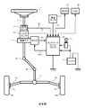
- the general configuration of the electric power steering apparatus will be described with reference to FIG. 6b is further connected to the steering wheels 8L and 8R via hub units 7a and 7b.
- the column shaft 2 is provided with a torque sensor 10 for detecting the steering torque Th of the handle 1 and a steering angle sensor 14 for detecting the steering angle ⁇ , and a motor 20 for assisting the steering force of the handle 1 is a reduction gear.
- 3 is connected to the column shaft 2 through 3.
- the control unit (ECU) 30 that controls the electric power steering apparatus is supplied with electric power from the battery 13 and also receives an ignition key signal via the ignition key 11.
- the control unit 30 calculates a current command value of an assist (steering assist) command based on the steering torque Th detected by the torque sensor 10 and the vehicle speed Vs detected by the vehicle speed sensor 12, and compensates the current command value.
- the current supplied to the EPS motor 20 is controlled by the voltage control command value Vref subjected to.
- the steering angle ⁇ is detected from the steering angle sensor 14, and the steering angle can be acquired from a rotation sensor such as a resolver connected to the motor 20.
- the control unit 100 is connected to a CAN (Controller Area Network) 40 that exchanges various vehicle information, and the vehicle speed Vel can be received from the CAN 40.
- the control unit 30 can be connected to a non-CAN 41 that exchanges communications, analog / digital signals, radio waves, and the like other than the CAN 40.
- the control unit 30 is mainly composed of a CPU (including an MPU, MCU, etc.).
- FIG. 2 shows general functions executed by a program inside the CPU.
- the steering torque Th detected by the torque sensor 10 and the vehicle speed Vs detected by the vehicle speed sensor 12 are a current command for calculating a current command value Iref1.
- the value is input to the value calculation unit 31.
- the current command value calculation unit 31 calculates a current command value Iref1, which is a control target value of the current supplied to the motor 20, using an assist map or the like based on the input steering torque Th and vehicle speed Vs.
- the voltage control command value Vref whose characteristics are improved by the PI control unit 34 is input to the PWM control unit 35, and the motor 20 is further PWM driven via the inverter 36.
- the current value Im of the motor 20 is detected by the motor current detector 37 and fed back to the subtraction unit 32B.
- the inverter 36 is composed of an FET bridge circuit as a semiconductor switching element.
- a rotation sensor 21 such as a resolver is connected to the motor 20, a motor rotation angle ⁇ is output from the rotation sensor 21, and a motor speed ⁇ is calculated by a motor speed calculation unit 22.
- the compensation signal CM from the compensation signal generation unit 38 is added to the addition unit 32A, and the compensation of the steering system system is performed by adding the compensation signal CM to improve the convergence property, the inertia property, and the like. ing.
- the compensation signal generator 38 adds the self-aligning torque (SAT) 38-1 and the inertia 38-2 by the adder 38-4, and further adds the convergence 38-3 to the addition result by the adder 38-5.
- the addition result of the adder 38-5 is used as the compensation signal CM.
- the details of the PWM control unit 35 and the inverter 36 are configured as shown in FIG. 3, for example, and the PWM control unit 35 sets the voltage control command value Vref to a three-phase according to a predetermined formula.
- the inverter 36 is constituted by a three-phase bridge (FET1 to FET6) of FETs as semiconductor switching elements, and drives the motor 20 by being turned ON / OFF by PWM duty values D1 to D6.
- a motor relay 23 for supplying (ON) or shutting off (OFF) power is connected to each phase of the power supply line between the inverter 36 and the motor 20.
- the angle sensor there are a resolver, a hall sensor, an MR sensor, and the like, and each method has a function of detecting the motor angle with a required accuracy.
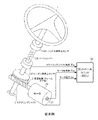
- FIG. 4 shows the overall configuration of the angle detection system.
- a steering shaft (column shaft) 2 connected to the handle 1 is provided with a torsion bar 2A, and the handle 1 is sandwiched between the handle 1 and the handle 1 side.
- a side angle sensor 14H is provided, and a pinion side angle 14P is provided on the pinion side.
- a rotation sensor 21 such as a resolver is attached to the motor 20 provided on the steering shaft 2 via the reduction gear 3.
- the pinion side angle ⁇ p detected by the pinion side angle sensor 14P, the motor angle ⁇ m from the rotation sensor 21, and the motor current Im detected by the current detection circuit are input to the control unit 30.
- an electric power steering employing a brushless motor is required to be equipped with an alternative means that can detect the angle even if the angle sensor of the motor fails.
- the angle (electrical angle) of the motor is estimated by monitoring and calculating the back electromotive voltage generated mainly when the motor rotates by the ECU.
- the present invention has been made under the circumstances as described above, and an object of the present invention is to provide an electric power steering capable of performing angle estimation using a motor regenerative current so that angle estimation can be performed with high accuracy even at low speed steering. To provide an apparatus.
- the present invention calculates a current command value based on at least a steering torque, and drives and controls a motor that applies an assist torque to a steering system based on the current command value with an inverter based on each phase of PWM, and the steering
- the present invention relates to an electric power steering apparatus that detects an angle of a system or the motor, and the object of the present invention includes an angle estimation unit that estimates the angle when the angle detection system fails, and is estimated by the angle estimation unit. This is achieved by performing assist control based on the estimated angle.
- the object of the present invention is that the angle estimation unit fixes each phase duty to 0% or 100% for detection of the regenerative current of the motor, or the motor current detection circuit performs lower switching of the inverter. If it is in contact with the element, the fixed duty is set to 0%, or if the motor current detection circuit is in contact with the upper switching element of the inverter, the fixed duty is set to 100%, or When the motor current detection circuit is arranged on the motor phase, it is possible to select the duty to be fixed at 0% or 100%, or the angle estimation unit can fix the phase of the motor while fixing all of the phases. By detecting the current, or the angle estimating unit is configured to estimate the angle from the detected motor current.
- the angle estimator corrects the estimated angle from the rotational direction of the steering shaft angle, or the angle estimator is a sign of the steering torque instead of the rotational direction of the steering shaft angle.
- the motor In a situation where the rotation does not rotate at all and the angle estimation is indefinite, the current is supplied to the motor to move the motor, and immediately after that, the respective phases are fixed to detect the current by fixing the duty. This is achieved more effectively.
- the present invention calculates a current command value based on at least a steering torque and applies a motor having two system windings for applying an assist torque to the steering system based on the current command value.
- the present invention relates to an electric power steering apparatus that controls driving by a system inverter and detects an angle of the steering system or the motor, and the object of the present invention is to estimate the angle when the angle detection system fails. Is achieved in each system, and assist control of each system is performed based on the estimated angle estimated by the angle estimation unit.
- the object of the present invention is that the angle estimation unit of each system fixes each phase Duty of each system to 0% or 100% in order to detect the regenerative current of the two systems winding, or a motor
- the fixed duty is set to 0%, or when the motor current detection circuit is in contact with the upper switching element of each system inverter.
- the duty to be fixed can be selected from 0% or 100%, or assist control is performed with two systems.
- the assist control of one system is stopped, or the assist control is performed on one system,
- the assist amount that is insufficient during angle estimation in the other system is compensated by increasing the assist amount of the system that is assist-controlling, or the regenerative current of the system that is estimating the angle.
- the duty release fixed mode and 0 [A] control are implemented so that the motor open relay is controlled to be ON / OFF so as not to become excessive, or the regenerative current of the system whose angle is estimated is not excessive.
- the duty to be fixed is not limited, and the same duty is applied to all three phases, and the necessary current value can be measured. It can be achieved more effectively by just being able to be Duty.
- the angle estimation using the motor regenerative current is performed, so that the angle estimation can be performed with high accuracy even at low speed steering. As a result, even if the angle detection system fails, the assist control can be continued.
- FIG. 3 is a block diagram showing a specific configuration example of the present invention.
- an angle estimation means for estimating the angle is provided, so that the steering assist function is continued by the estimated angle even if the angle detection system fails.
- a specific means of angle estimation is to intentionally fix the duty command values of all UVW phases to 0% at the timing when angle sensor failure occurs and angle estimation is necessary. This is because the motor is put into a complete electromagnetic brake mode, which adds a damping component to the steering system and causes an unstable state of vehicle behavior due to a sudden change in steering speed (e.g., yaw rate divergence or sudden steering torque during a turn).
- Duty is fixed to 0% for all phases of the ECU when the current detection method is the downstream shunt method ECU. If the current detection method is the upstream shunt method, the duty is fixed to 100% for all phases. A regenerative current can be detected, and if it is an ECU of a phase current detection system, it may be fixed at 0% or 100%.
- the assist control can be performed while the angle is estimated by alternately repeating the angle estimation (Duty 0% or 100% fixed) and the assist control.
- the angle estimation using the motor regenerative current is performed at the timing when the angle detection system breaks down so that the angle estimation can be accurately performed even at low speed steering.
- This method utilizes the fact that the internal impedance (resistance component) of the ECU and the impedance (resistance component) of the motor winding are sufficiently low.
- the impedance (resistance component) of the ECU and the motor is about 10 m ⁇ , so that a sufficient detection current value can be obtained even in a low-speed steering region where the amplitude is too small for the motor back electromotive voltage to be measured, and the accuracy is high. Angle estimation is possible.
- the optimal duty to be fixed varies depending on the motor current detection method. For example, when a current detection element such as a shunt resistor is arranged for current detection adjacent to the lower switching element, the duty regenerative current is fixed to 0% so that all motor regenerative current flows through the shunt resistance. To. On the contrary, when the current detection element is arranged adjacent to the upper switching element, the duty is fixed to 100%.
- the duty may be either 100% or 0%.
- the motor regenerative current can be detected with high accuracy even at an extremely low steering speed (for example, 10 deg / s or less), and the electrical angle can be estimated from the magnitude relationship of the three-phase currents.
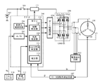
- FIG. 5 shows a configuration example of the present invention, and the angle detection system is the same as in FIG.
- the ECU 200 includes an MCU 230, a stabilized power supply circuit 201, an A / D conversion unit 202, and the like.
- the MCU 230 has functions of a failure determination unit 210, an angle estimation unit 220, a torque direction determination unit 221, and a correction unit 222. is doing.
- the ECU 200 inputs the calculated phase duty to the FET gate drive circuit 130 and drives the motor 100 via the inverter 140. Electric power is supplied to the inverter 140 from the battery 105 via the switch unit 131, and the switch unit 131 is turned ON / OFF by the ECU 200. In addition, electric power is supplied from the battery 105 to the ECU 200, and an ignition key signal from the ignition key 104 is input to the ECU 200 and the switch unit 131.
- a resolver 101 is connected to the rotor of the motor 100 as a rotation sensor, a detection signal from the resolver 101 is input to the rotor rotation angle detection circuit 102, and the detected rotation angle ⁇ is input to the ECU 200. Further, the phase current of the motor 100 is detected by the current detection circuit 103, and the detected phase current Ip is input to the ECU 200. Further, the steering torque Th detected by the torque sensor 110 is converted into a digital value by the A / D converter 202 and input to the MCU 230, and the vehicle speed Vs from the vehicle speed sensor 111 is input to the MCU 230.
- the steering torque Th is input from the torque sensor 110, and the vehicle speed Vs is input from the vehicle speed sensor 111 (step S1).
- the ECU 200 (MCU 230) calculates a current command value based on the steering torque Th and the vehicle speed Vs (step S2), and calculates each phase Duty (step S3).
- the motor 100 is driven through the gate drive circuit 130 and the inverter 140 (step S4).
- the phase current Ip is detected by the current detection circuit 103, and the rotation angle ⁇ is detected by the rotor rotation angle detection circuit 102 and is input to the ECU 200, respectively.
- the failure determination unit 210 in the MCU 230 determines whether a failure (including abnormality) has occurred in the angle sensor (resolver 101 or the like) during the assist control as described above (step S5).
- step S5 when the failure determination unit 210 determines that a failure has occurred in the angle sensor, the duty 100 is fixed to 0% and the driving of the motor 100 is stopped (step S10). It is determined whether or not the amplitude of the phase current Ip detected in step S is equal to or greater than a threshold value Pth (step S11). When the amplitude of the phase current Ip is smaller than the threshold value Pth, the process returns to step S10. Note that the threshold value Pth is larger than the noise amplitude of the current detection value after A / D conversion. A smaller threshold value Pth can be set by reducing noise by filter processing or the like.
- the angle estimation unit 220 in the MCU 230 estimates an electrical angle from the phase current Ip (step S12).
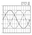
- An embodiment for estimating the electrical angle from the phase current Ip has characteristics as shown in FIG. That is, for example, when the U phase and the V phase are positive values and the W phase is a negative value, the estimated angle is estimated to be in the range of 0 to 60 °. More finely, when the V phase is larger than the U phase, the range is estimated to be 0 to 30 °. Conversely, when the U phase is larger than the V phase, the range is estimated to be 30 to 60 °. Similarly, with respect to other angles, the angle in increments of 30 ° can be estimated from the sign of the current and the magnitude relationship.
- the torque direction determination unit 221 in the ECU 200 determines the direction of the torque applied to the motor 100 from the movement of the pinion side angle (step S13).
- the estimated angle estimated in step S12 is shifted by 180 ° when the direction of the torque applied to (generated) the motor 100 is reversed. Therefore, the steering shaft angle ⁇ p, which is the pinion side angle (output shaft angle), of the column shaft changes.
- the direction of the torque applied to the motor 100 is estimated from the direction (the change direction of the angle means the rotation direction), and if necessary, corrected by 180 °.
- the steering shaft angle ⁇ p rotates in the CW direction
- the motor 100 generates a brake torque for the CW rotation because the three phases are short-circuited. Since this brake torque is opposite to the rotational direction, the direction of the torque of the motor 100 is CCW. Conversely, when the steering shaft angle ⁇ p rotates in the CCW direction, the direction of torque of the motor 100 is CW.
- the correction unit 222 in the MCU 230 corrects the estimated electrical angle from the torque direction determined by the torque direction determination unit 221 (step S14).
- the phase current Ip of the motor 100 has a characteristic that the polarity is reversed when the torque direction of the motor 100 is reversed. That is, when the motor torque in the CW direction is generated at an angle of 90 ° and when the motor torque in the CCW direction is generated at an angle of 270 °, the same phase current sign and magnitude relationship are obtained. Therefore, for example, assuming that the relationship between the current and the angle shown in FIG. 7 is that the torque generated by the motor 100 is in the CW direction, the correction unit 222 assumes that the estimated angle is obtained when the torque of the motor 100 is in the CCW direction.
- the correct angle can be estimated by correcting the offset by 180 °.
- the ECU 200 releases the fixed duty of each phase at 0% (step S15), and performs the same assist control as usual with the corrected estimated angle (step S16).
- the current detection circuit 103 is arranged between the motor phases so that the duty is fixed to 0%, but may be fixed to 100%. If a current detection element such as a current detection shunt resistor is placed adjacent to the FET (Q2, Q4, Q6) at the lower stage of the inverter, the duty regenerative current is fixed at 0% and all motor regeneration currents are fixed. To flow through the shunt resistor. On the contrary, when the current detection element is arranged adjacent to the upper FET (Q1, Q3, Q5) of the inverter, the duty is fixed to 100%.
- the angle estimation unit 220 may determine the torque direction using the sign of the steering torque Th or the sign of the differential value of the steering torque Th instead of the steering shaft angle (pinion side angle), and fixing each phase Duty.
- the time time required for angle estimation
- the angle estimation unit 220 moves the motor 100 by supplying a current to the motor 100 when the motor 100 does not rotate at all and the angle estimation is indefinite.
- the angle estimation unit 220 fixes each phase duty and supplies the current.
- the angle may be estimated by detection.
- FIG. 8 shows a Y-connected three-phase motor.
- One system is composed of a U-phase winding UW1, a V-phase winding VW1, and a W-phase winding WW1, and the other one is a U-phase winding UW2, V It consists of a phase winding VW2 and a W-phase winding WW2.
- the motor is driven by passing a three-phase current through the windings UW1 to WW1 or the windings UW2 to WW2.
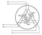
- FIG. 9 shows a delta-connected three-phase motor.
- One system is composed of a U-phase winding UW1, a V-phase winding VW1, and a W-phase winding WW1, and the other one is a U-phase winding UW2. , V-phase winding VW2 and W-phase winding WW2.
- the motor is driven by passing a three-phase current through the windings UW1 to WW1 or the windings UW2 to WW2.
- the present invention can also be applied to an electric power steering apparatus driven by a motor having such a multi-system winding, and a configuration example thereof is shown in FIG. 10 corresponding to FIG.
- drive control of a motor 150 having two Y-connected windings (L1: L1u to L1w, L2: L2u to L2w) will be described.
- the motor control unit that drives the motor 150 having two-system motor windings includes a control unit 150A that drives and controls the winding L1 (L1u to L1w), and a control unit 150B that drives and controls the winding L2 (L2u to L2w). It consists of Control units 150A and 150B have the same configuration, and control units 150A and 150B are controlled by ECUs 200A and 200B, respectively.
- Each of the ECUs 200A and 200B includes at least functions of a failure determination unit 210A and 210B, an angle estimation unit 220A and 220B, a torque direction determination unit 221A and 221B, and a correction unit 222A and 222B.
- ECUs 200A and 200B are input with steering torque Th, vehicle speed Vs, and rotation angle ⁇ from rotor rotation angle detection circuit 102, and motor current I1d detected from each phase coil of motor winding L1 of the first system is input to ECU 200A.
- (Iu1, Iv1, Iw1) is input
- the motor current I2d (Iu2, Iv2, Iw2) detected from each phase coil of the motor winding L2 of the second system is input to the ECU 200B.
- the duty drive signal GtA calculated as described above is input to gate drive circuit 130A
- the duty drive signal GtB calculated in ECU 200B is input to gate drive circuit 130B.
- the failure signal SAa determined by the failure determination unit 210A in the ECU 200A is input to the gate drive circuit 130A
- the failure signal SAb determined by the failure determination unit 210B in the ECU 200B is input to the gate drive circuit 130B.
- a direct current is supplied to the control units 150A and 150B from the battery 105 as a direct current power source through the noise filter 106 and further through power supply cutoff circuits 131A and 131B which are turned on / off by the gate drive circuits 130A and 130B, respectively.
- Each of the power cutoff circuits 131A and 131B has a series circuit configuration in which two FETs QC1, QC2 and QD1, QD2 connect sources to each other and a parasitic diode is reverse.
- the drains of the FETs QC1 and QD1 are connected to each other and connected to the output side of the noise filter 106, and the drains of the FETs QC2 and QD2 are connected to the sources of the FETs Q1, Q2, and Q3 of the inverters 122A and 122B.
- the power supply smoothing electrolytic capacitors CA and CB are connected in parallel to the power supply units of the inverters 140A and 140B. Further, between the inverter 140A and the winding L1 of the motor 150, a motor release relay 132A composed of current interrupting FETs QA1, QA2, and QA3 is connected, and between the inverter 140B and the winding L2 of the motor 150, A motor open relay 132B composed of FETs QB1, QB2 and QB3 for current interruption is connected.
- the FETs QA1 to QA3 and QB1 to QB3 of the motor opening relays 132A and 132B are connected in the same direction with the cathodes of the respective parasitic diodes D as the inverters 140A and 140B.
- the ECU 200A drives the winding L1 of the motor 150 via the gate drive circuit 130A and the inverter 140A based on the calculated drive signal GtA when the failure of the angle detection system is not determined and the failure signal SAa is not output.
- the ECU 200B drives the winding L2 of the motor 150 via the gate drive circuit 130B and the inverter 140B based on the calculated drive signal GtB when the failure of the angle detection system is not determined and the failure signal SAb is not output.
- the gate drive circuit 130A fixes the duty to 0% or 100% and controls the power cutoff circuit 131A and the motor release relay 132A by OF / OFF as necessary.
- the gate drive circuit 130B fixes the duty to 0% or 100%, and performs the OF / OFF control of the power cutoff circuit 131B and the motor release relay 132B as necessary.
- one system can be used exclusively for driving, and the other system can be used only for estimating the angle from the motor current.
- the duty is fixed to 0% to 100%, and the motor current is always detected to continuously estimate the angle.
- the other side performs assist control using the estimated angle. By doing in this way, it becomes possible to perform angle estimation and assist control simultaneously, and it becomes possible to make a smoother steering feeling. Further, since the motor of the system with the fixed duty always generates the brake torque, the assist control system can cancel the change in steering feeling by generating the assist torque that cancels the brake torque.
- ON / OFF control of the motor opening relay of the system with fixed duty can be performed so as not to cause excessive braking torque.
- the same effect can be obtained by alternately repeating the duty fixed mode and the 0 [A] control at high speed.
- the duty to be fixed is not limited, and it is sufficient that the duty is the same for all three phases and the required current value can be measured.
Landscapes
- Engineering & Computer Science (AREA)
- Chemical & Material Sciences (AREA)
- Combustion & Propulsion (AREA)
- Transportation (AREA)
- Mechanical Engineering (AREA)
- Power Engineering (AREA)
- Steering Control In Accordance With Driving Conditions (AREA)
- Power Steering Mechanism (AREA)
- Control Of Ac Motors In General (AREA)
- Control Of Motors That Do Not Use Commutators (AREA)
Abstract
Description
2A トーションバー
2 コラム軸(ステアリングシャフト、ハンドル軸)
10、110 トルクセンサ
12、111 車速センサ
14H ハンドル側角度センサ
14P ピニオン側角度センサ
20、100、150 モータ
23 モータ開放スイッチ
30、200 コントロールユニット(ECU)
31 電流指令値演算部
34 PI制御部
35 PWM制御部
36、140 インバータ
101 レゾルバ
102 ロータ回転角検出回路
103 電流検出回路
130 FETゲート駆動回路
210 故障判定部
220 角度推定部
221 トルク方向判定部
222 補正部
230 MCU
Claims (22)
- 少なくとも操舵トルクに基づいて電流指令値を演算し、前記電流指令値に基づいて操舵系にアシストトルクを付与するモータを、PWMの各相Dutyによるインバータで駆動制御すると共に、前記操舵系若しくは前記モータの角度を検出する電動パワーステアリング装置において、
前記角度の検出系が故障したときに前記角度を推定する角度推定部を備え、前記角度推定部で推定された推定角度に基づいてアシスト制御を行うことを特徴とする電動パワーステアリング装置。 - 前記角度推定部は、前記モータの回生電流の検出のために前記各相Dutyを0%若しくは100%に固定する請求項1に記載の電動パワーステアリング装置。
- モータ電流検出回路が前記インバータの下段スイッチング素子と接している場合は、固定するDutyを0%とする請求項2に記載の電動パワーステアリング装置。
- モータ電流検出回路が前記インバータの上段スイッチング素子と接している場合は、固定するDutyを100%とする請求項2に記載の電動パワーステアリング装置。
- モータ電流検出回路がモータ相上に配置されている場合は、固定するDutyを0%若しくは100%で選択できる請求項2に記載の電動パワーステアリング装置。
- 前記角度推定部は、前記各相Dutyの全てを固定中に前記モータの電流を検出するようになっている請求項1乃至5のいずれかに記載の電動パワーステアリング装置。
- 前記角度推定部は、検出されたモータ電流から前記角度を推定するようになっている請求項6に記載の電動パワーステアリング装置。
- 前記角度推定部は、ステアリングシャフト角度の回転方向から推定角度を補正するようになっている請求項1乃至7のいずれかに記載の電動パワーステアリング装置。
- 前記角度推定部は、ステアリングシャフト角度の回転方向の代わりに前記操舵トルクの符号若しくは前記操舵トルクの微分値の符号を用いている請求項1乃至7のいずれかに記載の電動パワーステアリング装置。
- 前記各相Dutyの固定時間を操舵速度及びアシストトルクなどの状況に応じて変更できる請求項1乃至9のいずれかに記載の電動パワーステアリング装置。
- 前記角度推定部は、前記モータが全く回転しない状況で、且つ角度推定が不定の場合は、前記モータへ電流を流して前記モータを動かし、その直後に前記各相Dutyを固定して電流を検出することで角度推定を行うようになっている請求項6乃至9のいずれかに記載の電動パワーステアリング装置。
- 少なくとも操舵トルクに基づいて電流指令値を演算し、前記電流指令値に基づいて操舵系にアシストトルクを付与する2系統巻線を有するモータを、PWMの各相Dutyによる各系統インバータで駆動制御すると共に、前記操舵系若しくは前記モータの角度を検出する電動パワーステアリング装置において、
前記角度の検出系が故障したときに前記角度を推定する角度推定部を各系統に備え、前記角度推定部で推定された推定角度に基づいて各系統のアシスト制御を行うことを特徴とする電動パワーステアリング装置。 - 前記各系統の角度推定部は、前記2系統巻線の回生電流の検出のために前記各系統の各相Dutyを0%若しくは100%に固定する請求項12に記載の電動パワーステアリング装置。
- モータ電流検出回路が前記各系統インバータの下段スイッチング素子と接している場合は、固定するDutyを0%とする請求項12は13に記載の電動パワーステアリング装置。
- モータ電流検出回路が前記各系統インバータの上段スイッチング素子と接している場合は、固定するDutyを100%とする請求項12又は13に記載の電動パワーステアリング装置。
- モータ電流検出回路がモータ相上に配置されている場合は、固定するDutyを0%若しくは100%で選択できる請求項12又は13に記載の電動パワーステアリング装置。
- 2系統でアシスト制御しておき、角度推定が必要となった時だけ、一方系統のアシスト制御を停止するようになっている請求項12乃至16のいずれかに記載の電動パワーステアリング装置。
- 一方の系統でアシスト制御し、他方の系統で角度推定している間に不足するアシスト量は、アシスト制御している系統のアシスト量を増加させることで補うようになっている請求項12乃至16のいずれかに記載の電動パワーステアリング装置。
- 角度推定している系統の回生電流が過大にならないように、モータ開放リレーをON/OFF制御するようになっている請求項12乃至18のいずれかに記載の電動パワーステアリング装置。
- 角度推定している系統の回生電流が過大にならないように、Duty固定モードと0[A]制御を高速に交互に切り替えるようになっている請求項12乃至18のいずれかに記載の電動パワーステアリング装置。
- 角度推定している系統が発生するブレーキトルクを相殺するアシストトルクをアシストする系統で発生させるようになっている請求項12乃至16のいずれかに記載の電動パワーステアリング装置。
- 前記各系統のインバータのデッドタイムの影響を考慮しない場合は、固定するDutyは限定せずに3相とも同じDutyとし、且つ必要な電流値が測定できるDutyであれば良い請求項21に記載の電動パワーステアリング装置。
Priority Applications (6)
| Application Number | Priority Date | Filing Date | Title |
|---|---|---|---|
| EP16846579.7A EP3351456B1 (en) | 2015-09-18 | 2016-09-15 | Electric power steering device |
| CN201680048717.0A CN107922001B (zh) | 2015-09-18 | 2016-09-15 | 电动助力转向装置 |
| KR1020187007173A KR101885842B1 (ko) | 2015-09-18 | 2016-09-15 | 전동 파워 스티어링 장치 |
| BR112018013744A BR112018013744A2 (pt) | 2015-09-18 | 2016-09-15 | aparelho de direção assistida elétrica |
| US15/751,315 US10286949B2 (en) | 2015-09-18 | 2016-09-15 | Electric power steering apparatus |
| JP2017539976A JP6281665B2 (ja) | 2015-09-18 | 2016-09-15 | 電動パワーステアリング装置 |
Applications Claiming Priority (4)
| Application Number | Priority Date | Filing Date | Title |
|---|---|---|---|
| JP2015185871 | 2015-09-18 | ||
| JP2015-185871 | 2015-09-18 | ||
| JP2016010958 | 2016-01-22 | ||
| JP2016-010958 | 2016-01-22 |
Publications (1)
| Publication Number | Publication Date |
|---|---|
| WO2017047708A1 true WO2017047708A1 (ja) | 2017-03-23 |
Family
ID=58289370
Family Applications (1)
| Application Number | Title | Priority Date | Filing Date |
|---|---|---|---|
| PCT/JP2016/077311 Ceased WO2017047708A1 (ja) | 2015-09-18 | 2016-09-15 | 電動パワーステアリング装置 |
Country Status (7)
| Country | Link |
|---|---|
| US (1) | US10286949B2 (ja) |
| EP (1) | EP3351456B1 (ja) |
| JP (5) | JP6281665B2 (ja) |
| KR (1) | KR101885842B1 (ja) |
| CN (1) | CN107922001B (ja) |
| BR (1) | BR112018013744A2 (ja) |
| WO (1) | WO2017047708A1 (ja) |
Cited By (5)
| Publication number | Priority date | Publication date | Assignee | Title |
|---|---|---|---|---|
| JP2019054612A (ja) * | 2017-09-14 | 2019-04-04 | 日本精工株式会社 | モータ制御装置及びそれを搭載した電動パワーステアリング装置 |
| EP3483036A1 (en) * | 2017-11-09 | 2019-05-15 | Jtekt Corporation | Steering control apparatus |
| JP2019084983A (ja) * | 2017-11-07 | 2019-06-06 | 株式会社ジェイテクト | 操舵制御装置 |
| JP2019119417A (ja) * | 2018-01-11 | 2019-07-22 | 株式会社デンソー | 電動パワーステアリング装置 |
| WO2024095355A1 (ja) * | 2022-11-01 | 2024-05-10 | 三菱電機株式会社 | 電動パワーステアリング装置 |
Families Citing this family (12)
| Publication number | Priority date | Publication date | Assignee | Title |
|---|---|---|---|---|
| US11267528B2 (en) | 2017-10-20 | 2022-03-08 | Shimano Inc. | Bicycle device and brake system |
| KR102631269B1 (ko) * | 2019-04-03 | 2024-01-30 | 에이치엘만도 주식회사 | 전동 파워스티어링용 모터 제어 장치 및 그 방법 |
| CN110104058B (zh) * | 2019-04-26 | 2024-06-11 | 淮阴工学院 | 一种基于电磁直线执行器的汽车助力转向系统 |
| US11485407B2 (en) | 2019-05-16 | 2022-11-01 | Lightning Systems, Inc. | Smart electronic power steering system and method for a retrofitted electric vehicle |
| JP7211515B2 (ja) * | 2020-02-13 | 2023-01-24 | 日本精工株式会社 | 位相調整方法、補正値算出装置、モータ制御装置、電動アクチュエータ製品及び電動パワーステアリング装置 |
| JP7540920B2 (ja) * | 2020-09-07 | 2024-08-27 | 株式会社ジェイテクト | モータの制御装置 |
| JP7565788B2 (ja) | 2020-12-23 | 2024-10-11 | 富士フイルム株式会社 | 磁気テープ装置、磁気テープおよび磁気テープカートリッジ |
| BR112023025760A2 (pt) * | 2021-06-28 | 2024-02-27 | Jfe Steel Corp | Método de estimativa de quantidade de calor suprido, dispositivo de estimativa de quantidade de calor suprido, programa de estimativa de quantidade de calor suprido e método de operação de alto-forno |
| WO2023275914A1 (ja) | 2021-06-28 | 2023-01-05 | 三菱電機株式会社 | 自動運転支援装置 |
| JP7586008B2 (ja) * | 2021-07-14 | 2024-11-19 | 株式会社デンソー | モータ制御装置 |
| KR102634428B1 (ko) * | 2021-12-27 | 2024-02-06 | 디와이씨스 주식회사 | 모터제어방법 및 그 장치 |
| KR102888522B1 (ko) * | 2025-08-12 | 2025-11-24 | 주식회사 이에스피 | 주행 안전 대응 dc 모터 토크 제어 기반 차량 조향 제어 장치 |
Citations (5)
| Publication number | Priority date | Publication date | Assignee | Title |
|---|---|---|---|---|
| JP2005349860A (ja) * | 2004-06-08 | 2005-12-22 | Honda Motor Co Ltd | モータ駆動回路および電動パワーステアリング装置 |
| JP2008049773A (ja) * | 2006-08-23 | 2008-03-06 | Nsk Ltd | 電動パワーステアリング制御装置 |
| JP2010070037A (ja) * | 2008-09-18 | 2010-04-02 | Mitsubishi Electric Corp | 電動パワーステアリング装置 |
| JP2011078230A (ja) * | 2009-09-30 | 2011-04-14 | Denso Corp | 多相回転機の制御装置、および、これを用いた電動パワーステアリング装置 |
| JP2014087213A (ja) * | 2012-10-25 | 2014-05-12 | Kubota Corp | モータ制御装置 |
Family Cites Families (24)
| Publication number | Priority date | Publication date | Assignee | Title |
|---|---|---|---|---|
| JPS5168057A (en) | 1974-12-10 | 1976-06-12 | Mitsubishi Electric Corp | Erebeetano senpatsukagoshiteisochi |
| JPS5822078B2 (ja) | 1979-07-17 | 1983-05-06 | 旭化成株式会社 | 羊毛蝋の高度精製方法 |
| JP2722750B2 (ja) | 1990-02-14 | 1998-03-09 | 松下電器産業株式会社 | ブラシレスモータの駆動装置 |
| JP3381408B2 (ja) * | 1993-10-26 | 2003-02-24 | トヨタ自動車株式会社 | 電気角検出装置およびこれを用いた同期モータの駆動装置 |
| JP3636340B2 (ja) | 1997-06-30 | 2005-04-06 | 富士電機機器制御株式会社 | 交流回転機用電力変換装置 |
| JP3353664B2 (ja) * | 1997-07-30 | 2002-12-03 | トヨタ自動車株式会社 | 電気角検出装置 |
| JP3598909B2 (ja) * | 1998-09-30 | 2004-12-08 | 株式会社日立製作所 | 同期モータ制御装置及び電気車制御装置並びに同期モータ制御方法 |
| US6979975B1 (en) | 2000-03-27 | 2005-12-27 | Mitsubishi Denki Kabushiki Kaisha | Rotation state detecting apparatus of a synchronous machine |
| JP4269686B2 (ja) | 2003-01-09 | 2009-05-27 | 株式会社明電舎 | 同期電動機の位置・速度・電圧振幅のセンサレス計測方法およびセンサレス可変速装置 |
| JP4103051B2 (ja) | 2003-11-28 | 2008-06-18 | 富士電機機器制御株式会社 | 交流電動機用電力変換装置 |
| JP2007174721A (ja) * | 2005-12-19 | 2007-07-05 | Mitsubishi Heavy Ind Ltd | ブラシレスdcモータの初期回転位置検出装置及び初期回転位置検出方法 |
| JP5012258B2 (ja) | 2006-09-07 | 2012-08-29 | 日本精工株式会社 | 電動パワーステアリング装置 |
| JP5168057B2 (ja) | 2008-09-29 | 2013-03-21 | 日本精工株式会社 | 電動パワーステアリング装置 |
| JP2011010401A (ja) * | 2009-06-24 | 2011-01-13 | Jtekt Corp | モータ制御装置および電動パワーステアリング装置 |
| JP5263079B2 (ja) | 2009-08-26 | 2013-08-14 | トヨタ自動車株式会社 | 電動パワーステアリング装置 |
| JP5433657B2 (ja) * | 2011-09-15 | 2014-03-05 | 株式会社東芝 | モータ制御装置 |
| JP5449429B2 (ja) * | 2012-02-24 | 2014-03-19 | 三菱電機株式会社 | 交流回転機の制御装置及びその方法、電動パワーステアリング装置 |
| JP5502126B2 (ja) | 2012-03-26 | 2014-05-28 | 三菱電機株式会社 | 多重巻線回転機の駆動装置 |
| JP5614598B2 (ja) | 2012-12-26 | 2014-10-29 | 株式会社ジェイテクト | モータ制御装置 |
| JP6022951B2 (ja) * | 2013-01-18 | 2016-11-09 | トヨタ自動車株式会社 | 電動パワーステアリング装置 |
| WO2014126563A1 (en) * | 2013-02-14 | 2014-08-21 | Otis Elevator Company | Elevator car speed control in a battery powered elevator system |
| JP2015039256A (ja) | 2013-03-15 | 2015-02-26 | 日本精工株式会社 | モータ制御装置、これを使用した電動パワーステアリング装置及び車両 |
| JP6129677B2 (ja) | 2013-08-05 | 2017-05-17 | 日立オートモティブシステムズ株式会社 | 電動モータの駆動制御装置 |
| JP6108043B2 (ja) * | 2014-09-04 | 2017-04-05 | 日本精工株式会社 | モータ制御装置、故障検出方法並びにそれらを搭載した電動パワーステアリング装置及び車両 |
-
2016
- 2016-09-15 CN CN201680048717.0A patent/CN107922001B/zh active Active
- 2016-09-15 US US15/751,315 patent/US10286949B2/en active Active
- 2016-09-15 WO PCT/JP2016/077311 patent/WO2017047708A1/ja not_active Ceased
- 2016-09-15 BR BR112018013744A patent/BR112018013744A2/pt unknown
- 2016-09-15 EP EP16846579.7A patent/EP3351456B1/en active Active
- 2016-09-15 KR KR1020187007173A patent/KR101885842B1/ko not_active Expired - Fee Related
- 2016-09-15 JP JP2017539976A patent/JP6281665B2/ja active Active
-
2018
- 2018-01-23 JP JP2018008990A patent/JP6635129B2/ja active Active
- 2018-01-23 JP JP2018008988A patent/JP6635127B2/ja active Active
- 2018-01-23 JP JP2018008987A patent/JP6624213B2/ja active Active
- 2018-01-23 JP JP2018008989A patent/JP6635128B2/ja active Active
Patent Citations (5)
| Publication number | Priority date | Publication date | Assignee | Title |
|---|---|---|---|---|
| JP2005349860A (ja) * | 2004-06-08 | 2005-12-22 | Honda Motor Co Ltd | モータ駆動回路および電動パワーステアリング装置 |
| JP2008049773A (ja) * | 2006-08-23 | 2008-03-06 | Nsk Ltd | 電動パワーステアリング制御装置 |
| JP2010070037A (ja) * | 2008-09-18 | 2010-04-02 | Mitsubishi Electric Corp | 電動パワーステアリング装置 |
| JP2011078230A (ja) * | 2009-09-30 | 2011-04-14 | Denso Corp | 多相回転機の制御装置、および、これを用いた電動パワーステアリング装置 |
| JP2014087213A (ja) * | 2012-10-25 | 2014-05-12 | Kubota Corp | モータ制御装置 |
Cited By (8)
| Publication number | Priority date | Publication date | Assignee | Title |
|---|---|---|---|---|
| JP2019054612A (ja) * | 2017-09-14 | 2019-04-04 | 日本精工株式会社 | モータ制御装置及びそれを搭載した電動パワーステアリング装置 |
| JP2019084983A (ja) * | 2017-11-07 | 2019-06-06 | 株式会社ジェイテクト | 操舵制御装置 |
| EP3483036A1 (en) * | 2017-11-09 | 2019-05-15 | Jtekt Corporation | Steering control apparatus |
| US10538266B2 (en) | 2017-11-09 | 2020-01-21 | Jtekt Corporation | Steering control apparatus |
| JP2019119417A (ja) * | 2018-01-11 | 2019-07-22 | 株式会社デンソー | 電動パワーステアリング装置 |
| WO2024095355A1 (ja) * | 2022-11-01 | 2024-05-10 | 三菱電機株式会社 | 電動パワーステアリング装置 |
| JPWO2024095355A1 (ja) * | 2022-11-01 | 2024-05-10 | ||
| JP7721016B2 (ja) | 2022-11-01 | 2025-08-08 | 三菱電機モビリティ株式会社 | 電動パワーステアリング装置 |
Also Published As
| Publication number | Publication date |
|---|---|
| JP6624213B2 (ja) | 2019-12-25 |
| JP2018088809A (ja) | 2018-06-07 |
| CN107922001A (zh) | 2018-04-17 |
| JP6281665B2 (ja) | 2018-02-21 |
| EP3351456B1 (en) | 2020-03-04 |
| KR101885842B1 (ko) | 2018-08-06 |
| JP2018088810A (ja) | 2018-06-07 |
| KR20180032656A (ko) | 2018-03-30 |
| BR112018013744A2 (pt) | 2019-02-05 |
| US20180229764A1 (en) | 2018-08-16 |
| CN107922001B (zh) | 2020-10-27 |
| JPWO2017047708A1 (ja) | 2018-04-19 |
| US10286949B2 (en) | 2019-05-14 |
| EP3351456A1 (en) | 2018-07-25 |
| JP2018088808A (ja) | 2018-06-07 |
| JP2018088807A (ja) | 2018-06-07 |
| JP6635129B2 (ja) | 2020-01-22 |
| JP6635127B2 (ja) | 2020-01-22 |
| JP6635128B2 (ja) | 2020-01-22 |
| EP3351456A4 (en) | 2018-11-21 |
Similar Documents
| Publication | Publication Date | Title |
|---|---|---|
| JP6281665B2 (ja) | 電動パワーステアリング装置 | |
| JP5907314B2 (ja) | モータ制御装置、これを使用した電動パワーステアリング装置および車両 | |
| JP6195044B1 (ja) | 電動パワーステアリング装置 | |
| JP6004025B2 (ja) | モータ制御装置、これを使用した電動パワーステアリング装置および車両 | |
| US8710775B2 (en) | Electric power steering apparatus | |
| US11081995B2 (en) | Motor control device | |
| JP2006044338A (ja) | 電動パワーステアリング装置 | |
| WO2010001579A1 (ja) | モータ制御装置およびそれを備えた車両用操舵装置 | |
| WO2016009976A1 (ja) | モータ制御装置並びにそれを搭載した電動パワーステアリング装置及び車両 | |
| US8981690B2 (en) | Electric power steering system | |
| JP5397664B2 (ja) | モータ制御装置 | |
| JP2009248962A (ja) | 電動パワーステアリング装置 | |
| JP2016096608A (ja) | モータ制御装置、これを使用した電動パワーステアリング装置および車両 | |
| JP2011103738A (ja) | モータ制御装置および車両用操舵装置 | |
| JP2010213549A (ja) | モータ制御装置 |
Legal Events
| Date | Code | Title | Description |
|---|---|---|---|
| 121 | Ep: the epo has been informed by wipo that ep was designated in this application |
Ref document number: 16846579 Country of ref document: EP Kind code of ref document: A1 |
|
| DPE1 | Request for preliminary examination filed after expiration of 19th month from priority date (pct application filed from 20040101) | ||
| ENP | Entry into the national phase |
Ref document number: 2017539976 Country of ref document: JP Kind code of ref document: A |
|
| WWE | Wipo information: entry into national phase |
Ref document number: 15751315 Country of ref document: US |
|
| ENP | Entry into the national phase |
Ref document number: 20187007173 Country of ref document: KR Kind code of ref document: A |
|
| NENP | Non-entry into the national phase |
Ref country code: DE |
|
| REG | Reference to national code |
Ref country code: BR Ref legal event code: B01A Ref document number: 112018013744 Country of ref document: BR |
|
| ENPW | Started to enter national phase and was withdrawn or failed for other reasons |
Ref document number: 112018013744 Country of ref document: BR Free format text: PEDIDO RETIRADO EM RELACAO AO BRASIL, TENDO EM VISTA A NAO ACEITACAO DA ENTRADA NA FASE NACIONAL FACE A INTEMPESTIVIDADE, POIS O PRAZO PARA A REFERIDA ENTRADA EXPIRAVA EM 18/03/2018 (30 MESES CONTADOS DA DATA DE PRIORIDADE) E A ENTRADA SO OCORREU EM 04/07/2018. |
|
| ENPZ | Former announcement of the withdrawal of the entry into the national phase was wrong |
Ref document number: 112018013744 Country of ref document: BR Free format text: ANULADA A PUBLICACAO CODIGO 1.2 NA RPI NO 2506 DE 15/01/2019 POR TER SIDO INDEVIDA. |
|
| REG | Reference to national code |
Ref country code: BR Ref legal event code: B01D Ref document number: 112018013744 Country of ref document: BR Kind code of ref document: A2 Free format text: O PRESENTE PEDIDO FOI DEPOSITADO ATRAVES DO PCT/JP2016 077311 EM 15/09/2016 DANDO ENTRADA NA FASE NACIONAL EM 04/07/2018, APESAR DO PRAZO EXPIRAR EM 18/03/2018 (30 MESES CONTADOS DA DATA DE PRIORIDADE QUE E 18/09/2015).JUNTAMENTE, COM A PETICAO DE ENTRADA, O DEPOSITANTE SOLICITOU CONCESSAO DE PRAZO ADICIONAL OU RESTABELECIMENTO DE DIREITO DE ENTRADA NA FASE NACIONAL, JUSTIFICANDO QUE POR MOTIVO TOTALMENTE IMPREVISTO, ALHEIO A VONTADE DA PARTE, NAO FOI POSSIVEL REALIZAR O DEPOSITO DENTRO DO PRAZO.O REQUERENTE ALEGA QUE HOUVE UMA FALHA NAO INTENCIONAL, OU SEJA, ?O MOTIVO PARA O NAO CUMPRIMENTO DESTE PRAZO SE DEU POR CONTA DE UM PROBLEMA DE SISTEMAS/INTERNET, OCORRE QUE A INSTRUCAO DE NOSSO CLI |
|
| ENP | Entry into the national phase |
Ref document number: 112018013744 Country of ref document: BR Kind code of ref document: A2 Effective date: 20180704 |
|
| ENPW | Started to enter national phase and was withdrawn or failed for other reasons |
Ref document number: 112018013744 Country of ref document: BR Kind code of ref document: A2 Free format text: EM ATENDIMENTO A DECISAO RECURSAL PUBLICADA NA RPI 2717 DE 31/01/2023, FOI MANTIDA A DECISAO PUBLICADA PRIMARIAMENTE NA RPI 2523 DE 14/05/2019, SENDO DESTE MODO RETIRADO O REFERENTE PEDIDO EM RELACAO A ENTRADA NA FASE NACIONAL BRASILEIRA. |