WO2017047754A1 - スパッタリングターゲット材 - Google Patents
スパッタリングターゲット材 Download PDFInfo
- Publication number
- WO2017047754A1 WO2017047754A1 PCT/JP2016/077459 JP2016077459W WO2017047754A1 WO 2017047754 A1 WO2017047754 A1 WO 2017047754A1 JP 2016077459 W JP2016077459 W JP 2016077459W WO 2017047754 A1 WO2017047754 A1 WO 2017047754A1
- Authority
- WO
- WIPO (PCT)
- Prior art keywords
- particle size
- less
- sputtering target
- target material
- powder
- Prior art date
- Legal status (The legal status is an assumption and is not a legal conclusion. Google has not performed a legal analysis and makes no representation as to the accuracy of the status listed.)
- Ceased
Links
Classifications
-
- C—CHEMISTRY; METALLURGY
- C23—COATING METALLIC MATERIAL; COATING MATERIAL WITH METALLIC MATERIAL; CHEMICAL SURFACE TREATMENT; DIFFUSION TREATMENT OF METALLIC MATERIAL; COATING BY VACUUM EVAPORATION, BY SPUTTERING, BY ION IMPLANTATION OR BY CHEMICAL VAPOUR DEPOSITION, IN GENERAL; INHIBITING CORROSION OF METALLIC MATERIAL OR INCRUSTATION IN GENERAL
- C23C—COATING METALLIC MATERIAL; COATING MATERIAL WITH METALLIC MATERIAL; SURFACE TREATMENT OF METALLIC MATERIAL BY DIFFUSION INTO THE SURFACE, BY CHEMICAL CONVERSION OR SUBSTITUTION; COATING BY VACUUM EVAPORATION, BY SPUTTERING, BY ION IMPLANTATION OR BY CHEMICAL VAPOUR DEPOSITION, IN GENERAL
- C23C14/00—Coating by vacuum evaporation, by sputtering or by ion implantation of the coating forming material
- C23C14/22—Coating by vacuum evaporation, by sputtering or by ion implantation of the coating forming material characterised by the process of coating
- C23C14/34—Sputtering
- C23C14/3407—Cathode assembly for sputtering apparatus, e.g. Target
- C23C14/3414—Metallurgical or chemical aspects of target preparation, e.g. casting, powder metallurgy
-
- C—CHEMISTRY; METALLURGY
- C22—METALLURGY; FERROUS OR NON-FERROUS ALLOYS; TREATMENT OF ALLOYS OR NON-FERROUS METALS
- C22C—ALLOYS
- C22C19/00—Alloys based on nickel or cobalt
- C22C19/07—Alloys based on nickel or cobalt based on cobalt
-
- C—CHEMISTRY; METALLURGY
- C22—METALLURGY; FERROUS OR NON-FERROUS ALLOYS; TREATMENT OF ALLOYS OR NON-FERROUS METALS
- C22C—ALLOYS
- C22C30/00—Alloys containing less than 50% by weight of each constituent
-
- C—CHEMISTRY; METALLURGY
- C22—METALLURGY; FERROUS OR NON-FERROUS ALLOYS; TREATMENT OF ALLOYS OR NON-FERROUS METALS
- C22C—ALLOYS
- C22C33/00—Making ferrous alloys
- C22C33/02—Making ferrous alloys by powder metallurgy
-
- C—CHEMISTRY; METALLURGY
- C22—METALLURGY; FERROUS OR NON-FERROUS ALLOYS; TREATMENT OF ALLOYS OR NON-FERROUS METALS
- C22C—ALLOYS
- C22C38/00—Ferrous alloys, e.g. steel alloys
-
- C—CHEMISTRY; METALLURGY
- C23—COATING METALLIC MATERIAL; COATING MATERIAL WITH METALLIC MATERIAL; CHEMICAL SURFACE TREATMENT; DIFFUSION TREATMENT OF METALLIC MATERIAL; COATING BY VACUUM EVAPORATION, BY SPUTTERING, BY ION IMPLANTATION OR BY CHEMICAL VAPOUR DEPOSITION, IN GENERAL; INHIBITING CORROSION OF METALLIC MATERIAL OR INCRUSTATION IN GENERAL
- C23C—COATING METALLIC MATERIAL; COATING MATERIAL WITH METALLIC MATERIAL; SURFACE TREATMENT OF METALLIC MATERIAL BY DIFFUSION INTO THE SURFACE, BY CHEMICAL CONVERSION OR SUBSTITUTION; COATING BY VACUUM EVAPORATION, BY SPUTTERING, BY ION IMPLANTATION OR BY CHEMICAL VAPOUR DEPOSITION, IN GENERAL
- C23C14/00—Coating by vacuum evaporation, by sputtering or by ion implantation of the coating forming material
- C23C14/22—Coating by vacuum evaporation, by sputtering or by ion implantation of the coating forming material characterised by the process of coating
- C23C14/34—Sputtering
Definitions
- the present invention relates to a sputtering target material useful for the production of alloy thin films such as magnetic tunnel junction (MTJ) elements, HDDs, magnetic recording media and the like.
- MTJ magnetic tunnel junction
- Magnetic random access memory has a magnetic tunnel junction (MTJ) element.
- the magnetic tunnel junction (MTJ) element has a structure such as CoFeB / MgO / CoFeB and exhibits characteristics such as a high tunneling magnetoresistance (TMR) signal and a low switching current density (Jc).
- TMR tunneling magnetoresistance
- Jc switching current density
- a CoFeB thin film of a magnetic tunnel junction (MTJ) element is formed by sputtering a CoFeB target.
- a CoFeB sputtering target material for example, as disclosed in JP-A-2004-346423 (Patent Document 1), a sputtering target material produced by sintering atomized powder is known.
- Patent Document 1 Although the method of producing a sputtering target material by sintering atomized powder as in Patent Document 1 is an effective technique, it is possible to produce a good target material only by the method described in Patent Document 1. Can not. That is, there is a problem that the strength of the sputtering target material is lowered simply by sintering the atomized powder.
- the present inventors have intensively developed and found that the mechanical strength of the sputtering target can be improved by reducing the hydrogen content in the sputtering target material.
- the invention has been completed.
- the present invention includes the following inventions.
- B is 10 to 50%, Ti, Zr, Hf, V, Nb, Ta, Cr, Mo, W, Mn, Re, Ru, Rh, Ir, Ni, Pd, Pt, Cu, Ag Sputtering characterized in that it contains 0 to 20% in total of one or more elements selected from the group consisting of at least one of Co and Fe and unavoidable impurities, and a hydrogen content of 20 ppm or less.
- Target material [2] at.
- sputtering target material according to [1] above containing a total of 5 to 20% of elements.
- sputtering target material according to [1] which has a bending strength of 200 MPa or more.
- a sputtering target material excellent in mechanical strength is provided.
- the B content is 10 to 50%.
- the content of B is less than 10%, the alloy thin film formed at the time of sputtering is not sufficiently amorphous.
- the hydrogen content is 20 ppm or less.
- the B content is adjusted to 10 to 50%.
- the content of B is preferably 20 to 50%.
- the total content of one or more elements selected from “element group” may be 0 to 20%.
- the total content of one or more elements selected from the element group means the content of the one element.
- the strength of the sputtering target material decreases, so that 1 selected from the above element group Content of the element more than a seed
- the total content of one or more elements selected from the above element group is preferably 12% or less, more preferably 10% or less.
- the total content is 0%.
- the sputtering target material according to the present invention contains one or more elements selected from the above element group, the total content can be appropriately adjusted in the range of more than 0 to 20%. is there.
- the balance consists of at least one of Co and Fe and inevitable impurities.
- Co and Fe are elements that impart magnetism, and the total content of Co and Fe is 30% or more.
- the “total content of Co and Fe” means the one content.
- the total content of Co and Fe is preferably 40% or more, more preferably 50% or more.
- the hydrogen content is 20 ppm or less.
- Hydrogen is an element inevitably present in a powder used as a raw material for the sputtering target material (for example, an atomized powder such as a gas atomized powder), but when the content of hydrogen remaining in the sputtering target material exceeds 20 ppm, Since the strength of the sputtering target material is reduced, the hydrogen content is adjusted to 20 ppm or less.
- the hydrogen content is preferably 10 ppm or less.
- the sputtering target material according to the present invention may contain other inevitable impurities up to 1000 ppm.
- Sputtering target material with a hydrogen content of 20 ppm or less is 10 to 50% B, Ti, Zr, Hf, V, Nb, Ta, Cr, Mo, W, Mn, Re, Ru, Rh, Ir, Ni From an atomized powder of an alloy containing at least one element selected from the group consisting of Pd, Pt, Pt, Cu, and Ag in a total amount of 0 to 20%, with the balance being at least one of Co and Fe and inevitable impurities , Removing coarse particles having a particle size of 500 ⁇ m or more, and then removing fine particles from the powder from which the coarse particles have been removed to prepare a powder satisfying any one of the particle size conditions A, B, and C; , B, and C can be manufactured by sintering.
- the particle size conditions A, B, and C are defined as follows.
- the particle size condition A is that, in the particle size distribution of the powder (particle group), the cumulative volume of particles having a particle size of 5 ⁇ m or less is 10% or less, and the cumulative volume of particles having a particle size of 30 ⁇ m or less is 40% or less.
- the particle size condition B in the particle size distribution of the powder (particle group), the cumulative volume of particles having a particle size of 5 ⁇ m or less is 8% or less, and the cumulative volume of particles having a particle size of 30 ⁇ m or less is 35% or less. Defined.
- the particle size condition C is that, in the particle size distribution of the powder (particle group), the cumulative volume of particles having a particle size of 5 ⁇ m or less is 5% or less and the cumulative volume of particles having a particle size of 30 ⁇ m or less is 30% or less.
- the powder satisfying all the particle size conditions A, B, and C is a powder satisfying the particle size condition C
- the powder satisfying the particle size conditions A and B is a powder satisfying the particle size condition B.
- “Particle size” and “particle size distribution” mean the particle size and particle size distribution measured by a laser diffraction / scattering particle size distribution measuring device (Microtrack).
- each particle size condition defines the particle size distribution by two conditions, namely, a first condition relating to the amount of particles having a particle size of 5 ⁇ m or less and a second condition relating to the amount of particles having a particle size of 30 ⁇ m or less.
- the first condition regulates the cumulative volume of particles having a particle size of 5 ⁇ m or less to 10% or less, and the second condition sets the cumulative volume of particles having a larger particle size of 30 ⁇ m or less to 40% or less. regulate.
- the particle size condition B the first condition regulates the cumulative volume of particles having a particle size of 5 ⁇ m or less to 8% or less, and the second condition regulates the cumulative volume of particles having a particle size of 30 ⁇ m or less to 35% or less.
- the first condition regulates the cumulative volume of particles with a particle size of 5 ⁇ m or less to 5% or less
- the second condition regulates the cumulative volume of particles with a particle size of 30 ⁇ m or less to 30% or less.
- the particle size conditions A, B, and C regulate the cumulative volume of particles having a particle size of 5 ⁇ m or less to be gradually reduced to 10% or less, 8% or less, and 5% or less.
- the cumulative volume is regulated so as to decrease stepwise to 40% or less, 35% or less, and 30% or less.
- the hydrogen content and the bending strength of a sputtering target material manufactured using a gas atomized powder satisfying any of the particle size conditions A, B, and C are shown.
- the powder satisfying any one of the particle size conditions A, B, and C is obtained by removing coarse particles not suitable for molding having a particle size of 500 ⁇ m or more from a powder (for example, an atomized powder such as a gas atomized powder) as a raw material of a sputtering target material. It can be prepared by removing fine particles from the powder from which coarse particles have been removed.
- a powder for example, an atomized powder such as a gas atomized powder
- the atomizing method for producing the atomized powder include a gas atomizing method, a water atomizing method, a disk atomizing method, a plasma atomizing method, and the like, and a gas atomizing method is preferable.
- Removal of coarse particles having a particle size of 500 ⁇ m or more can be performed by classification using a sieve having an opening of 500 ⁇ m or less, for example, an opening of 250 to 500 ⁇ m. Removal of fine particles for preparing a powder satisfying any of the particle size conditions A, B, and C can be performed by classification using a sieve having an opening of 5 ⁇ m or less and / or an opening of 30 ⁇ m or less.
- the hydrogen content can be reduced to 20 ppm or less. This can be processed into a disk shape by wire cutting, lathe processing, and planar polishing to produce a sputtering target material.
- the sputtering target material manufactured in this way has improved strength.
- the sputtering target material according to the present invention preferably has a bending strength of 200 MPa or more.
- the bending strength of the sputtering target material according to the present invention is, for example, 210 MPa or more, 220 MPa or more, 230 MPa or more, 240 MPa or more, 250 MPa or more, 260 MPa or more, 270 MPa or more, 280 MPa or more, 290 MPa or more, or 300 MPa or more.
- the bending strength is measured as follows.
- the three-point bending test a surface of 4 mm in length and 25 mm in width is squeezed in the thickness direction with a distance between supporting points of 20 mm, the stress (N) at that time is measured, and the three-point bending strength is calculated based on the following formula.
- Three-point bending strength (MPa) (3 ⁇ stress (N) ⁇ distance between support points (mm) / (2 ⁇ width of test piece (mm) ⁇ (thickness of test piece (mm) 2 )
- the sputtering target material according to the present invention will be specifically described with reference to examples.
- the hot water is discharged from a nozzle having a diameter of 8 mm at the bottom of the crucible, Gas atomization was performed with Ar gas.
- the solidification rate can be controlled by adjusting the Ar gas injection pressure. The greater the injection pressure, the greater the coagulation rate.
- the particle size distribution of the gas atomized powder can be adjusted by controlling the solidification rate. The faster the solidification rate, the smaller the width of the particle size distribution.
- the fine particles are removed from the powder from which the coarse particles have been removed.
- a powder satisfying any of C was prepared. Removal of coarse particles not suitable for molding having a particle size of 500 ⁇ m or more was performed by classification using a sieve having an opening of 500 ⁇ m. Removal of fine particles for preparing a powder satisfying the particle size condition A was performed by classification using a sieve having an opening of 35 ⁇ m. Removal of fine particles for preparing a powder satisfying the particle size condition B was performed by classification using a sieve having an opening of 30 ⁇ m.
- Removal of fine particles for preparing a powder satisfying the particle size condition C was performed by classification using a sieve having an opening of 25 ⁇ m.
- Particle size conditions A, B A powder satisfying any one of C was placed in a 110 ° C. oven to perform moisture drying, and the dried powder was used as a raw material powder.
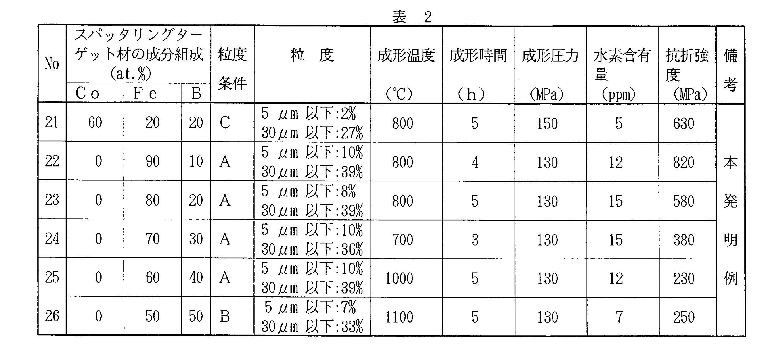
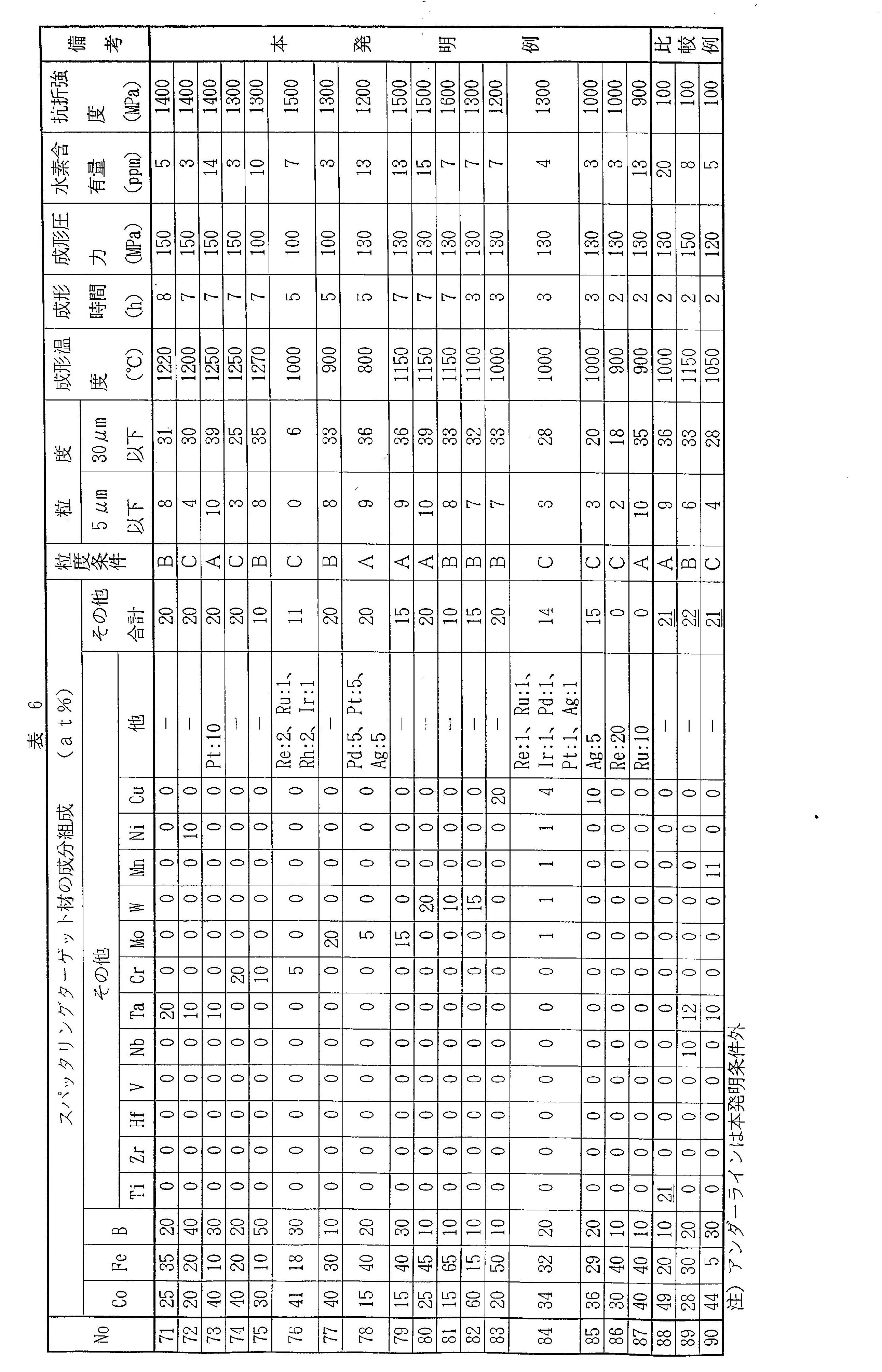
- the raw material powder was deaerated and charged into an SC can having an outer diameter of 220 mm, an inner diameter of 210 mm, and a length of 200 mm, and the powder-filled billet was sintered under the conditions shown in Table 1 or Table 2 to produce a sintered body. did.
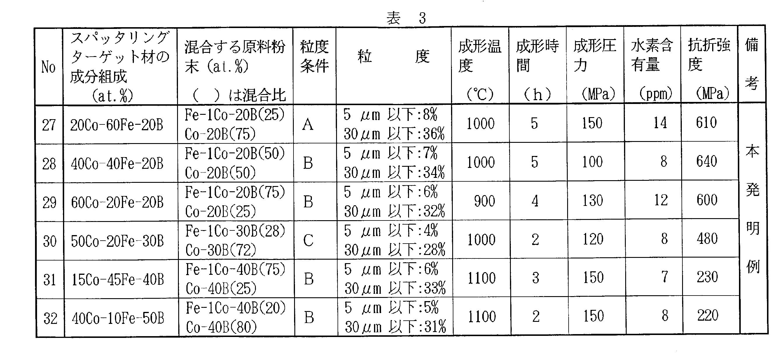
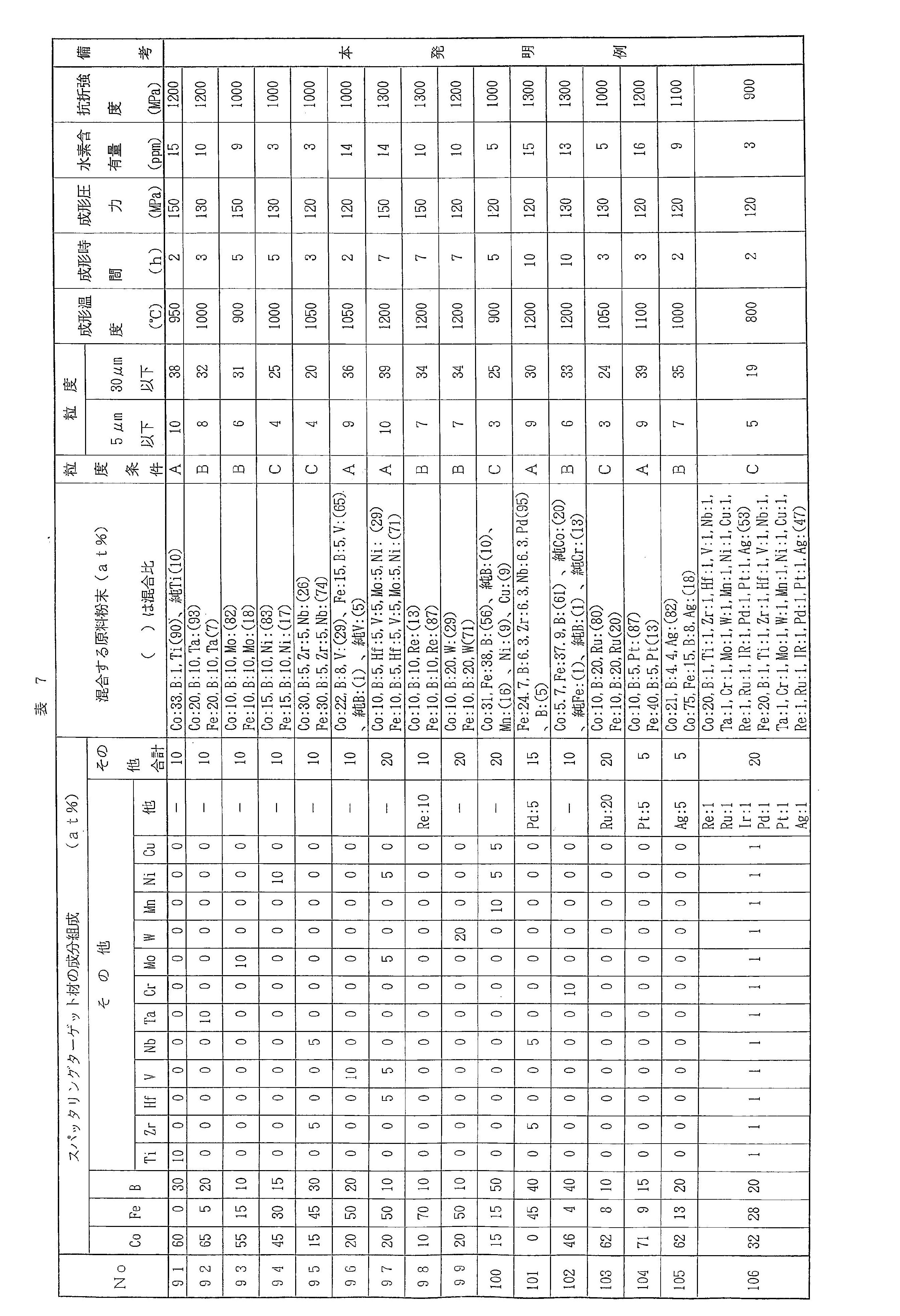
- dissolved raw materials were weighed for the component compositions shown in the raw material powder column of Tables 3 and 7, and, as in the case of the component compositions shown in Tables 1, 2, 5 and 6, a refractory crucible in a reduced pressure Ar gas atmosphere or vacuum atmosphere After melting by induction heating in the inside, the hot water was discharged from a nozzle having a diameter of 8 mm at the bottom of the crucible and gas atomized with Ar gas.
- pure Ti, pure B, pure V, and pure Cr are commercially available powders having a powder size of 150 ⁇ m or less.
- the powder from which the coarse particles have been removed is classified to remove fine particles.
- a powder satisfying any of C was prepared. Removal of coarse particles and fine particles was performed in the same manner as described above. A powder satisfying any one of the particle size conditions A, B, and C was placed in a 110 ° C. oven to perform moisture drying, and the dried powder was used as a raw material powder.
- the raw material powder was mixed at a mixing ratio shown in Table 3 for 30 minutes with a V-type mixer to have the composition shown in Table 3, and degassed into an SC can with an outer diameter of 220 mm, an inner diameter of 210 mm, and a length of 200 mm. I entered.
- the powder-filled billet was sintered under the conditions shown in Table 3 to produce a sintered body.
- the solidified molded body produced by the above method was processed into a disk shape having a diameter of 180 mm and a thickness of 7 mm by wire cutting, lathe processing, and planar polishing to obtain a sputtering target material.
- the raw material for melting was weighed and melted by induction heating in a refractory crucible in a reduced pressure Ar gas atmosphere or vacuum atmosphere, then poured out from a nozzle with a diameter of 8 mm at the bottom of the crucible, and Ar gas was used. Gas atomized. From the obtained gas atomized powder, coarse particles having a particle diameter of 500 ⁇ m or more not suitable for molding were removed, and the powder from which the coarse particles were removed was used as a raw material powder without removing fine particles. The raw material powder was deaerated and charged into an SC can having an outer diameter of 220 mm, an inner diameter of 210 mm, and a length of 200 mm.
- the powder-filled billet was sintered under the conditions shown in Table 4 to produce a sintered body.
- the solidified molded body produced by the above method was processed into a disk shape having a diameter of 180 mm and a thickness of 7 mm by wire cutting, lathe processing, and planar polishing to obtain a sputtering target material.
- the particle size distribution of the powder was confirmed by measuring with a laser diffraction / scattering particle size distribution measuring device (Microtrack). Moreover, a shaping
- molding method is HIP, hot press, SPS, hot extrusion, etc., for example, It does not specifically limit.
- the hydrogen content was measured by an inert gas melting-non-dispersive infrared absorption method.
- the mechanical strength (bending strength) was evaluated by a three-point bending test on a test piece having a length of 4 mm, a width of 25 mm, and a thickness of 3 mm determined by a wire.
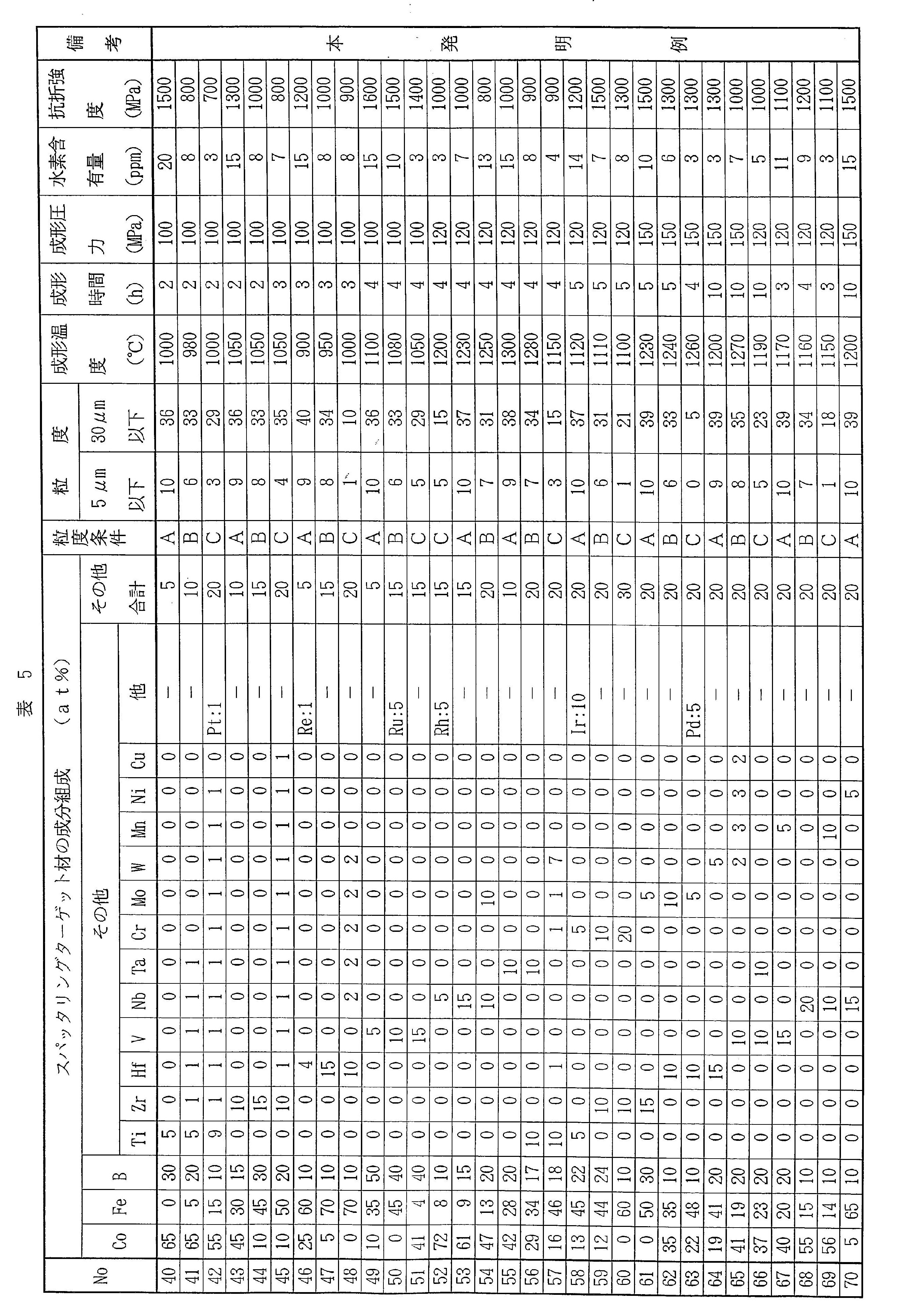
- 1-26 and no. Nos. 40 to 87 are sputtering target materials having the component compositions shown in Tables 1, 25 and 6.
- 27-32 and no. 91 to 106 are sputtering target materials manufactured from a plurality of raw material powders shown in Tables 3 and 7.
- B is 10 to 50%, Ti, Zr, Hf, V, Nb, Ta, Cr, Mo, W, Mn, Re, Ru, Rh, Ir, Ni, Pd, Pt, Cu, and Ag.
- the present invention satisfies the conditions of the present invention in which one or more elements selected from the group consisting of 0 to 20% in total are contained, the balance is at least one of Co and Fe, and inevitable impurities, and the hydrogen content is 20 ppm or less. Therefore, it was possible to achieve a bending strength of 200 MPa or more.
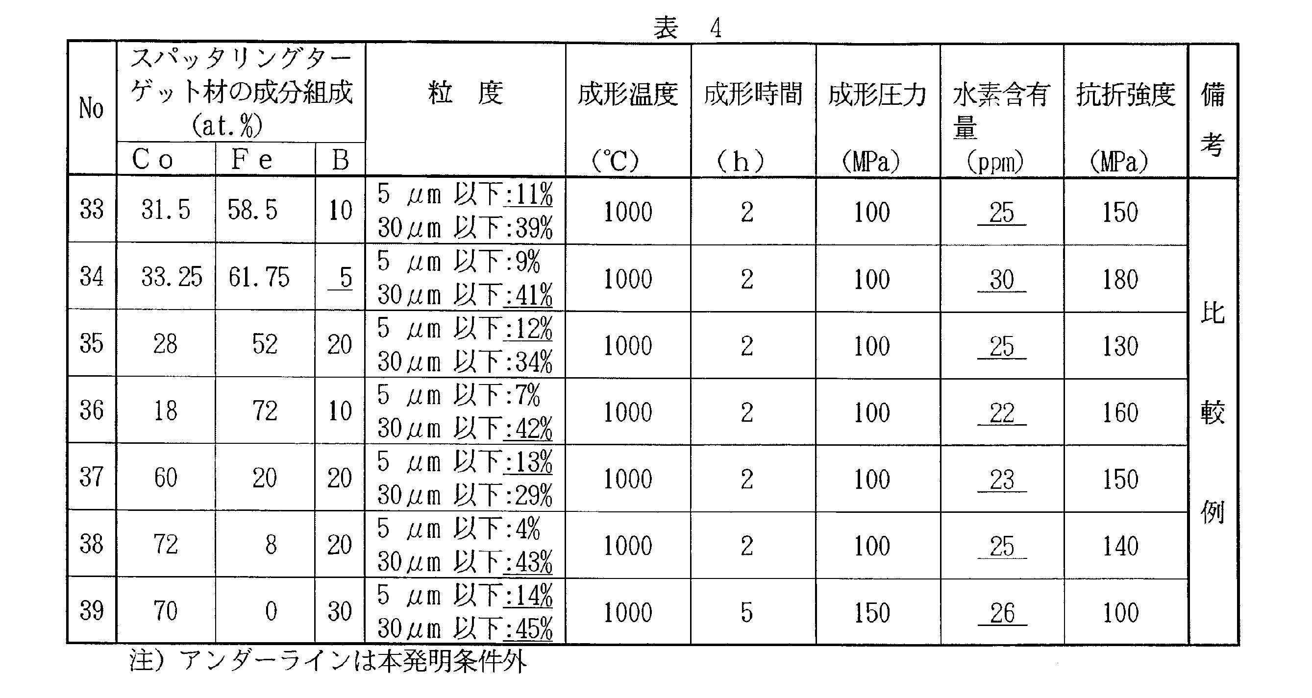
- Comparative Example No. shown in Table 4 was used.
- No. 33 has a cumulative volume of particles with a particle size of 5 ⁇ m or less in the particle size distribution of the gas atomized powder used as a raw material for the sputtering target material, 11%, and does not satisfy any of the particle size conditions A to C. Therefore, the hydrogen content is 25 ppm.
- the bending strength decreased to 150 MPa.
- Comparative Example No. 34 since the B content is less than 10% and the cumulative volume of particles having a particle size of 30 ⁇ m or less in the particle size distribution of the gas atomized powder used as the raw material of the sputtering target material is 41%, The amount increased to 30 ppm, and the bending strength decreased to 180 MPa.
- the cumulative volume of particles having a particle size of 5 ⁇ m or less in the particle size distribution of the gas atomized powder used as the raw material for the sputtering target material is 12% and 13%, and none of the particle size conditions A to C is satisfied.
- the hydrogen content increased to 25 ppm and 23 ppm, and the bending strength decreased to 130 MPa and 150 MPa.
- Comparative Example No. 36 and 38 the cumulative volume of particles having a particle size of 30 ⁇ m or less in the particle size distribution of the gas atomized powder used as the raw material for the sputtering target material is 42% and 43%, and none of the particle size conditions A to C is satisfied.
- the hydrogen content increased to 22 ppm and 25 ppm, and the bending strength decreased to 160 MPa and 140 MPa.
- Comparative Example No. No. 39 is a particle size distribution of the gas atomized powder used as the raw material of the sputtering target material, and the cumulative volume of particles having a particle size of 5 ⁇ m or less and 30 ⁇ m or less is 14% or 45%, and none of the particle size conditions A to C is satisfied.
- Comparative Example No. 88 to 90 are selected from the group consisting of Ti, Zr, Hf, V, Nb, Ta, Cr, Mo, W, Mn, Re, Ru, Rh, Ir, Ni, Pd, Pt, Cu, and Ag. Since the above elements are contained more than 20% in total, it can be seen that the strength is low and brittle.
- the present invention provides a sputtering target material having improved mechanical strength by reducing the hydrogen content in the sputtering target material to 20 ppm or less.
- the sputtering target material according to the present invention is a sputtering target material useful for the production of alloy thin films such as MTJ elements, HDDs, magnetic recording media and the like, and exhibits extremely excellent effects.
Landscapes
- Chemical & Material Sciences (AREA)
- Engineering & Computer Science (AREA)
- Materials Engineering (AREA)
- Mechanical Engineering (AREA)
- Metallurgy (AREA)
- Organic Chemistry (AREA)
- Chemical Kinetics & Catalysis (AREA)
- Powder Metallurgy (AREA)
- Physical Vapour Deposition (AREA)
- Manufacture Of Metal Powder And Suspensions Thereof (AREA)
Abstract
Description
[1]at.%で、Bを10~50%、Ti,Zr,Hf,V,Nb,Ta,Cr,Mo,W,Mn,Re,Ru,Rh,Ir,Ni,Pd,Pt,Cu,Agからなる群から選ばれる1種以上の元素を合計で0~20%含有し、残部がCoおよびFeの少なくとも1種と不可避的不純物とからなり、水素含有量が20ppm以下であることを特徴とする、スパッタリングターゲット材。
[2]at.%で、Ti,Zr,Hf,V,Nb,Ta,Cr,Mo,W,Mn,Re,Ru,Rh,Ir,Ni,Pd,Pt,Cu,Agからなる群から選ばれる1種以上の元素を合計で5~20%含有する、前記[1]に記載のスパッタリングターゲット材。
[3]200MPa以上の抗折強度を有する、前記[1]に記載のスパッタリングターゲット材。
CoおよびFeは、磁性を付与する元素であり、CoおよびFeの合計含有量は30%以上である。なお、本発明に係るスパッタリングターゲット材がCoおよびFeの一方のみを含有する場合、「CoおよびFeの合計含有量」は当該一方の含有量を意味する。CoおよびFeの合計含有量は、好ましくは40%以上、さらに好ましくは50%以上である。
粒度条件Aは、粉末(粒子群)の粒度分布において、粒径5μm以下の粒子の累積体積が10%以下、かつ、粒径30μm以下の粒子の累積体積が40%以下となっていることと定義される。
粒度条件Bは、粉末(粒子群)の粒度分布において、粒径5μm以下の粒子の累積体積が8%以下、かつ、粒径30μm以下の粒子の累積体積が35%以下となっていることと定義される。
粒度条件Cは、粉末(粒子群)の粒度分布において、粒径5μm以下の粒子の累積体積が5%以下、かつ、粒径30μm以下の粒子の累積体積が30%以下となっていることと定義される。
なお、粒度条件A,B,Cの全てを満たす粉末は、粒度条件Cを満たす粉末とし、粒度条件AおよびBを満たす粉末は、粒度条件Bを満たす粉末とする。また、「粒径」および「粒度分布」は、レーザー回折・散乱式粒子径分布測定装置(マイクロトラック)にて測定される粒径および粒度分布を意味する。
三点曲げ強度(MPa)=(3×応力(N)×支点間距離(mm)/(2×試験片の幅(mm)×(試験片の厚さ(mm)2)
表1、2、5、6に示す成分組成について、溶解原料を秤量し、減圧Arガス雰囲気または真空雰囲気の耐火物坩堝内で誘導加熱溶解した後、坩堝下部の直径8mmのノズルより出湯し、Arガスによりガスアトマイズした。なお、Arガスの噴射圧を調整することにより、凝固速度をコントロールすることができる。噴射圧が大きいほど、凝固速度が大きい。凝固速度のコントロールにより、ガスアトマイズ粉末の粒度分布を調整することができる。凝固速度が速いほど、粒度分布の幅は小さい。

三点曲げ強度(MPa)=(3×応力(N)×支点間距離(mm))/(2×試験片の幅(mm)×(試験片の厚さ(mm)2)
Claims (3)
- at.%で、Bを10~50%、Ti,Zr,Hf,V,Nb,Ta,Cr,Mo,W,Mn,Re,Ru,Rh,Ir,Ni,Pd,Pt,Cu,Agからなる群から選ばれる1種以上の元素を合計で0~20%含有し、残部がCoおよびFeの少なくとも1種と不可避的不純物とからなり、水素含有量が20ppm以下であることを特徴とする、スパッタリングターゲット材。
- at.%で、Ti,Zr,Hf,V,Nb,Ta,Cr,Mo,W,Mn,Re,Ru,Rh,Ir,Ni,Pd,Pt,Cu,Agからなる群から選ばれる1種以上の元素を合計で5~20%含有する、請求項1に記載のスパッタリングターゲット材。
- 200MPa以上の抗折強度を有する、請求項1に記載のスパッタリングターゲット材。
Priority Applications (5)
| Application Number | Priority Date | Filing Date | Title |
|---|---|---|---|
| US15/760,404 US20180265963A1 (en) | 2015-09-18 | 2016-09-16 | Sputtering Target Material |
| EP16846625.8A EP3351655A4 (en) | 2015-09-18 | 2016-09-16 | sputter target |
| KR1020187006795A KR102635337B1 (ko) | 2015-09-18 | 2016-09-16 | 스퍼터링 타겟재 |
| SG11201802203UA SG11201802203UA (en) | 2015-09-18 | 2016-09-16 | Sputtering target material |
| US16/986,331 US11377726B2 (en) | 2015-09-18 | 2020-08-06 | Sputtering target material |
Applications Claiming Priority (4)
| Application Number | Priority Date | Filing Date | Title |
|---|---|---|---|
| JP2015184846 | 2015-09-18 | ||
| JP2015-184846 | 2015-09-18 | ||
| JP2016010266A JP2017057490A (ja) | 2015-09-18 | 2016-01-22 | Co−Fe−B系合金ターゲット材 |
| JP2016-010266 | 2016-01-22 |
Related Child Applications (2)
| Application Number | Title | Priority Date | Filing Date |
|---|---|---|---|
| US15/760,404 A-371-Of-International US20180265963A1 (en) | 2015-09-18 | 2016-09-16 | Sputtering Target Material |
| US16/986,331 Continuation US11377726B2 (en) | 2015-09-18 | 2020-08-06 | Sputtering target material |
Publications (1)
| Publication Number | Publication Date |
|---|---|
| WO2017047754A1 true WO2017047754A1 (ja) | 2017-03-23 |
Family
ID=58289378
Family Applications (1)
| Application Number | Title | Priority Date | Filing Date |
|---|---|---|---|
| PCT/JP2016/077459 Ceased WO2017047754A1 (ja) | 2015-09-18 | 2016-09-16 | スパッタリングターゲット材 |
Country Status (1)
| Country | Link |
|---|---|
| WO (1) | WO2017047754A1 (ja) |
Cited By (1)
| Publication number | Priority date | Publication date | Assignee | Title |
|---|---|---|---|---|
| CN113084150A (zh) * | 2021-03-24 | 2021-07-09 | 河南东微电子材料有限公司 | 一种钌钴铼合金粉末的制备方法 |
Citations (6)
| Publication number | Priority date | Publication date | Assignee | Title |
|---|---|---|---|---|
| JP2003226963A (ja) * | 2002-02-04 | 2003-08-15 | Toshiba Corp | スパッタリングターゲット |
| JP2012207274A (ja) * | 2011-03-30 | 2012-10-25 | Hitachi Metals Ltd | 永久磁石薄膜用スパッタリングターゲット及びその製造方法 |
| WO2015019513A1 (ja) * | 2013-08-09 | 2015-02-12 | Jx日鉱日石金属株式会社 | ネオジム、鉄、ボロンを主成分とする希土類粉末又はスパッタリングターゲットの製造方法、同希土類元素からなる粉末又はスパッタリングターゲット及びネオジム、鉄、ボロンを主成分とする希土類磁石用薄膜又はその製造方法 |
| WO2015080009A1 (ja) * | 2013-11-28 | 2015-06-04 | Jx日鉱日石金属株式会社 | 磁性材スパッタリングターゲット及びその製造方法 |
| WO2015166762A1 (ja) * | 2014-05-01 | 2015-11-05 | 山陽特殊製鋼株式会社 | 磁気記録用軟磁性合金及びスパッタリングターゲット材並びに磁気記録媒体 |
| WO2016140113A1 (ja) * | 2015-03-04 | 2016-09-09 | Jx金属株式会社 | 磁性材スパッタリングターゲット及びその製造方法 |
-
2016
- 2016-09-16 WO PCT/JP2016/077459 patent/WO2017047754A1/ja not_active Ceased
Patent Citations (6)
| Publication number | Priority date | Publication date | Assignee | Title |
|---|---|---|---|---|
| JP2003226963A (ja) * | 2002-02-04 | 2003-08-15 | Toshiba Corp | スパッタリングターゲット |
| JP2012207274A (ja) * | 2011-03-30 | 2012-10-25 | Hitachi Metals Ltd | 永久磁石薄膜用スパッタリングターゲット及びその製造方法 |
| WO2015019513A1 (ja) * | 2013-08-09 | 2015-02-12 | Jx日鉱日石金属株式会社 | ネオジム、鉄、ボロンを主成分とする希土類粉末又はスパッタリングターゲットの製造方法、同希土類元素からなる粉末又はスパッタリングターゲット及びネオジム、鉄、ボロンを主成分とする希土類磁石用薄膜又はその製造方法 |
| WO2015080009A1 (ja) * | 2013-11-28 | 2015-06-04 | Jx日鉱日石金属株式会社 | 磁性材スパッタリングターゲット及びその製造方法 |
| WO2015166762A1 (ja) * | 2014-05-01 | 2015-11-05 | 山陽特殊製鋼株式会社 | 磁気記録用軟磁性合金及びスパッタリングターゲット材並びに磁気記録媒体 |
| WO2016140113A1 (ja) * | 2015-03-04 | 2016-09-09 | Jx金属株式会社 | 磁性材スパッタリングターゲット及びその製造方法 |
Cited By (2)
| Publication number | Priority date | Publication date | Assignee | Title |
|---|---|---|---|---|
| CN113084150A (zh) * | 2021-03-24 | 2021-07-09 | 河南东微电子材料有限公司 | 一种钌钴铼合金粉末的制备方法 |
| CN113084150B (zh) * | 2021-03-24 | 2023-08-25 | 河南东微电子材料有限公司 | 一种钌钴铼合金粉末的制备方法 |
Similar Documents
| Publication | Publication Date | Title |
|---|---|---|
| JP7084958B2 (ja) | Co-Fe-B系合金ターゲット材 | |
| EP1652960B1 (en) | Sputtering target and method for production thereof | |
| JP6483803B2 (ja) | 磁性材スパッタリングターゲット及びその製造方法 | |
| CA2584566C (en) | Sputtering target for producing metallic glass membrane and manufacturing method thereof | |
| RU2717767C2 (ru) | Распыляемая мишень | |
| TWI834821B (zh) | 適用於濺鍍靶材之合金 | |
| KR102620685B1 (ko) | 스퍼터링 타겟재 | |
| JP7506477B2 (ja) | スパッタリングターゲット材の製造方法 | |
| JP7086514B2 (ja) | コバルト製又はコバルト基合金製スパッタリングターゲット及びその製造方法 | |
| WO2017047754A1 (ja) | スパッタリングターゲット材 | |
| JP5661540B2 (ja) | 酸素含有量が低いCu−Ga系合金粉末、Cu−Ga系合金ターゲット材、およびターゲット材の製造方法 | |
| JP7492831B2 (ja) | スパッタリングターゲット材 | |
| TW202117031A (zh) | 磁性記錄媒體之種晶層用合金 | |
| JP4685059B2 (ja) | マンガン合金スパッタリングターゲット |
Legal Events
| Date | Code | Title | Description |
|---|---|---|---|
| 121 | Ep: the epo has been informed by wipo that ep was designated in this application |
Ref document number: 16846625 Country of ref document: EP Kind code of ref document: A1 |
|
| ENP | Entry into the national phase |
Ref document number: 20187006795 Country of ref document: KR Kind code of ref document: A |
|
| WWE | Wipo information: entry into national phase |
Ref document number: 15760404 Country of ref document: US |
|
| WWE | Wipo information: entry into national phase |
Ref document number: 11201802203U Country of ref document: SG |
|
| NENP | Non-entry into the national phase |
Ref country code: DE |
|
| WWE | Wipo information: entry into national phase |
Ref document number: 2016846625 Country of ref document: EP |