WO2017051890A1 - X線顕微鏡 - Google Patents
X線顕微鏡 Download PDFInfo
- Publication number
- WO2017051890A1 WO2017051890A1 PCT/JP2016/078070 JP2016078070W WO2017051890A1 WO 2017051890 A1 WO2017051890 A1 WO 2017051890A1 JP 2016078070 W JP2016078070 W JP 2016078070W WO 2017051890 A1 WO2017051890 A1 WO 2017051890A1
- Authority
- WO
- WIPO (PCT)
- Prior art keywords
- mirror
- concave
- ray
- convex
- ray microscope
- Prior art date
- Legal status (The legal status is an assumption and is not a legal conclusion. Google has not performed a legal analysis and makes no representation as to the accuracy of the status listed.)
- Ceased
Links
Images





Classifications
-
- G—PHYSICS
- G21—NUCLEAR PHYSICS; NUCLEAR ENGINEERING
- G21K—HANDLING OF PARTICLES OR IONISING RADIATION NOT OTHERWISE PROVIDED FOR; IRRADIATION DEVICES; GAMMA RAY OR X-RAY MICROSCOPES
- G21K7/00—Gamma- or X-ray microscopes
-
- G—PHYSICS
- G21—NUCLEAR PHYSICS; NUCLEAR ENGINEERING
- G21K—HANDLING OF PARTICLES OR IONISING RADIATION NOT OTHERWISE PROVIDED FOR; IRRADIATION DEVICES; GAMMA RAY OR X-RAY MICROSCOPES
- G21K1/00—Arrangements for handling particles or ionising radiation, e.g. focusing or moderating
- G21K1/06—Arrangements for handling particles or ionising radiation, e.g. focusing or moderating using diffraction, refraction or reflection, e.g. monochromators
-
- G—PHYSICS
- G21—NUCLEAR PHYSICS; NUCLEAR ENGINEERING
- G21K—HANDLING OF PARTICLES OR IONISING RADIATION NOT OTHERWISE PROVIDED FOR; IRRADIATION DEVICES; GAMMA RAY OR X-RAY MICROSCOPES
- G21K1/00—Arrangements for handling particles or ionising radiation, e.g. focusing or moderating
- G21K1/06—Arrangements for handling particles or ionising radiation, e.g. focusing or moderating using diffraction, refraction or reflection, e.g. monochromators
- G21K1/065—Arrangements for handling particles or ionising radiation, e.g. focusing or moderating using diffraction, refraction or reflection, e.g. monochromators using refraction, e.g. Tomie lenses
-
- G—PHYSICS
- G21—NUCLEAR PHYSICS; NUCLEAR ENGINEERING
- G21K—HANDLING OF PARTICLES OR IONISING RADIATION NOT OTHERWISE PROVIDED FOR; IRRADIATION DEVICES; GAMMA RAY OR X-RAY MICROSCOPES
- G21K1/00—Arrangements for handling particles or ionising radiation, e.g. focusing or moderating
- G21K1/06—Arrangements for handling particles or ionising radiation, e.g. focusing or moderating using diffraction, refraction or reflection, e.g. monochromators
- G21K1/067—Arrangements for handling particles or ionising radiation, e.g. focusing or moderating using diffraction, refraction or reflection, e.g. monochromators using surface reflection, e.g. grazing incidence mirrors, gratings
-
- G—PHYSICS
- G21—NUCLEAR PHYSICS; NUCLEAR ENGINEERING
- G21K—HANDLING OF PARTICLES OR IONISING RADIATION NOT OTHERWISE PROVIDED FOR; IRRADIATION DEVICES; GAMMA RAY OR X-RAY MICROSCOPES
- G21K2201/00—Arrangements for handling radiation or particles
- G21K2201/06—Arrangements for handling radiation or particles using diffractive, refractive or reflecting elements
- G21K2201/064—Arrangements for handling radiation or particles using diffractive, refractive or reflecting elements having a curved surface
-
- G—PHYSICS
- G21—NUCLEAR PHYSICS; NUCLEAR ENGINEERING
- G21K—HANDLING OF PARTICLES OR IONISING RADIATION NOT OTHERWISE PROVIDED FOR; IRRADIATION DEVICES; GAMMA RAY OR X-RAY MICROSCOPES
- G21K2207/00—Particular details of imaging devices or methods using ionizing electromagnetic radiation such as X-rays or gamma rays
Definitions
- the present invention relates to an X-ray microscope, and more particularly to an X-ray microscope using a Kirkpatrick-Baez mirror.
- the X-ray microscope is an imaging optical system using an electromagnetic wave having a very short wavelength, in principle, it has a high resolution of sub-nm far exceeding that of the optical microscope. In addition, it is possible to observe a three-dimensional tomographic image of a thick sample, which is difficult with a transmission electron microscope, due to the high transmission power of X-rays. Furthermore, since an X-ray microscope basically does not require the formation of a vacuum, it is suitable for observation in an environment that requires in-situ measurement (for example, an atmosphere of an aqueous solution and a gas).
- Promising candidates for imaging elements in X-ray microscopes include Fresnel zone plates, X-ray refractive lenses, Kirkpatrick-Baez (KB) mirrors, and Wolter mirrors.
- the Fresnel zone plate and the X-ray refractive lens can be manufactured sufficiently accurately to achieve sub-50 nm resolution.
- Fresnel zone plates are not suitable for multicolor imaging due to chromatic aberration caused by diffraction. Since the KB mirror employs total reflection, there is no chromatic aberration. However, since it is difficult to satisfy Abbe's sine condition with a single reflection in an oblique incidence optical system such as a KB mirror, coma aberration occurs, reducing resolution and field of view (FOV).
- the Wolter mirror is an excellent X-ray imaging system in that chromatic aberration and coma are eliminated.
- the mirror surface of the Wolter mirror is composed of a spheroid and a hyperboloid arranged on the inner surface of the cylinder, realizing diffraction-limited resolution. It is difficult to process the Wolter mirror with the required shape accuracy (on the order of 1 nm). Therefore, wavefront aberration based on a shape error in a Wolter mirror is a serious problem that cannot be avoided at present, and there has been no report of producing a mirror with a shape accuracy enough to exhibit high resolution performance (100 nm or less). .
- an X-ray optical system using a KB mirror for example, as in Patent Document 1, four obliquely incident total reflection X-ray mirrors of a horizontal elliptical mirror, a vertical elliptical mirror, a horizontal hyperbolic mirror, and a vertical hyperbolic mirror are used.
- a horizontal stage and a vertical stage are arranged along the optical axis direction of the X-ray, and a horizontal elliptic mirror and a horizontal hyperbolic mirror are provided on the horizontal stage so that they can be finely adjusted.
- an alignment monitoring means for providing a reference for finely adjusting the horizontal postures of the horizontal elliptical mirror and the horizontal hyperbolic mirror and the vertical postures of the vertical elliptical mirror and the vertical hyperbolic mirror so as to be an ideal posture within an error, respectively. is there.
- the X-ray optical system of Patent Document 1 achieves reduction or expansion of X-rays of 2 keV or higher without aberration with high resolution of 200 nm or lower.
- An object of the present invention is to provide an X-ray microscope of a compact size that is indoor carry-in size and can be widely used.
- the X-ray microscope of the present invention that has solved the above problems includes an X-ray source, a sample holder, a Kirkpatrick-Baez mirror (hereinafter referred to as a “concave KB mirror”) having a reflective concave surface, and a reflective convex surface. It has a Kirkpatrick-Baez mirror (hereinafter referred to as a “convex KB mirror”) and a light receiving part in an imaging relationship with the position of the sample holding part in order along the optical axis.
- a Kirkpatrick-Baez mirror hereinafter referred to as a “convex KB mirror”
- a light receiving part in an imaging relationship with the position of the sample holding part in order along the optical axis.
- the concave KB mirror is arranged on the sample holding unit side and the convex KB mirror is arranged on the light receiving unit side, so the position of the main surface of the lens system and the sample holding unit
- the distance (front focal length) can be made smaller than before. This makes it possible to dramatically shorten the distance between the position of the main surface of the lens system, which is the rear focal length, and the light receiving unit, assuming that the magnification is about the same as that of the conventional optical system.
- An X-ray microscope with a length of 2 to 3 meters can be realized.
- the reflective concave surface of the concave KB mirror includes an elliptical shape, and the sample holder is at a focal position of the elliptical shape.
- the reflective convex surface of the convex KB mirror includes the one curve among hyperbolas including one curve and the other curve, and the light receiving unit is on the other curve side of the focal point of the hyperbola. It is desirable to be in the focal position.
- a mode in which the distance between the concave KB mirror and the light receiving portion is longer than the distance between the convex KB mirror and the light receiving portion can be preferably implemented.
- a mode in which a main surface of an imaging system including the convex KB mirror and the concave KB mirror exists between the sample holder and the concave KB mirror can be preferably implemented.
- a mode in which the distance between the position of the sample holding part and the position of the light receiving part is within 2.5 m can be preferably implemented.
- At least two convex KB mirrors are arranged, at least two concave KB mirrors are arranged, and the normal line of one convex KB mirror and the normal line of the other convex KB mirror are
- a configuration in which the normal lines of one concave KB mirror and the normal lines of the other concave KB mirror are not parallel to each other can be preferably implemented.
- the shortest distance between the sample holder and the concave KB mirror is 6 mm or more.
- At least one of the convex KB mirror and the concave KB mirror is installed to be movable in the optical axis direction.
- a first concave KB mirror and a second concave KB mirror are disposed between the sample holder and the concave KB mirror, and the normal line of the concave KB mirror and the first concave KB mirror are arranged. It is desirable that the normal lines of the concave KB mirror are not parallel to each other, and the normal line of the convex KB mirror and the normal line of the second concave KB mirror are not parallel to each other.
- the first concave KB mirror is closer to the sample holder than the second concave KB mirror, the reflective concave surface of the first concave KB mirror includes a hyperbola, and the second concave KB mirror
- the reflective concave surface desirably includes an ellipse.
- the X-ray microscope of the present invention includes an X-ray source, a sample holding unit, a concave KB mirror, a convex KB mirror, and a light receiving unit in an imaging relationship with the position of the sample holding unit.
- the rear focal length of the optical system can be shortened while maintaining the enlargement magnification, and thus, the conventional X-ray microscope can be made into an indoor carry-in size, that is, a popular size at a stretch. Therefore, the industrial utility value by expanding the use of the X-ray microscope in various scientific fields is great.
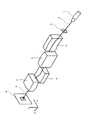
- FIG. 1 is a perspective view of an optical system of an X-ray microscope according to Embodiment 1 of the present invention.
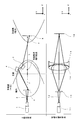
- FIG. 2 is a schematic diagram (upper part) of the X-ray optical system shown in FIG. 1 and visible light having a geometric optical function equivalent to the optical element used in the X-ray optical system for reference. It is the figure which wrote together the optical system (lower stage part).
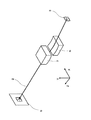
- FIG. 3 is a perspective view of the optical system of the X-ray microscope according to Embodiment 2 of the present invention.
- FIG. 4 is a diagram showing a PSF obtained by the X-ray microscope according to the second embodiment.
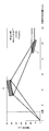
- FIG. 5 shows an X-ray optical path of the X-ray microscope according to the third embodiment.
- FIG. 6 shows the X-ray optical path of the X-ray microscope in Comparative Example 1.
- FIG. 7 shows the X-ray optical path of the X-ray microscope in the fourth embodiment.
- FIG. 8 shows the X-ray optical path of the X-ray microscope in Comparative Example 2.
- FIG. 9 shows the X-ray optical path of the X-ray microscope in the fifth embodiment.
- FIG. 10 shows the X-ray optical path of the X-ray microscope in Comparative Example 3.
- FIG. 11 is a perspective view of the optical system of the X-ray microscope according to Embodiment 6 of the present invention.
- FIG. 12 shows the X-ray optical path (X-axis projection) of the X-ray microscope in the sixth embodiment.
- FIG. 13 shows an X-ray optical path (Y-axis projection) of the X-ray microscope according to the sixth embodiment.
- the X-ray microscope of the present invention includes an X-ray source, a sample holding unit, a concave KB mirror, a convex KB mirror, and a light receiving unit located at an imaging relationship with the position of the sample holding unit along the optical axis. In order, at least one each. With this configuration, the rear focal length of the optical system can be shortened while maintaining the magnification of the X-ray microscope.
- the X-ray source, the sample holding unit, the concave KB mirror, the convex KB mirror, and the light receiving unit which are basic requirements of the present invention, will be described in order.
- X-ray source Although not particularly limited as long as it has a function of emitting X-rays, a small X-ray tube for laboratory use is preferably used, and a synchrotron radiation facility (such as SPring-8) can also be used. . Similar to an ordinary optical microscope using visible light, an X-ray microscope preferably uses Koehler illumination or critical illumination, and preferably uses a light source capable of realizing such illumination. In addition, since it is difficult to perform complex Koehler illumination in the X-ray region, usually, critical illumination is performed, or X-rays having a width of the visual field are appropriately irradiated.
- the X-ray energy is not particularly limited, and soft X-rays, X-rays, and hard X-rays can be used. In order to obtain a high resolution within 200 nm, X-rays and hard X-rays having energy of 2 keV or more are preferable. It is desirable to use lines.
- sample holder may be any instrument as long as it has a function of holding a sample to be observed on the optical path of X-rays.
- it may be a stage for simply placing a sample, may be two dielectric plates for holding the sample, a single dielectric plate for fixing the sample, A frame or the like for suspending the sample, or a container for holding a liquid sample may be used, and any form of instrument having a function of holding the sample on the X-ray optical path is used as the sample holding unit. be able to.
- the material constituting the sample holder but when the sample holder directly hits X-rays, it is desirable to use an X-ray transmissive material. In addition, it is desirable to select a material that is unlikely to accumulate charges due to X-ray irradiation.
- the KB mirror used in the present invention is a one-dimensional condensing mirror having a curvature only in one direction. Since the KB mirror is close to a flat plate shape, the surface processing is easier than the Wolter mirror.
- the incident angle of X-rays by the KB mirror is generally about several milliradians, and about 80 to 90% of the incident X-rays are reflected. When the incident angle is large, the ratio of transmitting through the KB mirror increases.
- the portion where the reflection surface is curved is sufficient even if it is within the range irradiated with X-rays. Even if it deteriorates, the mirror shape should be continuously formed over a long section in the other direction orthogonal to the one direction having the curvature so that the surface not irradiated with X-rays can be used by sliding the KB mirror. Is preferred.
- the length of the mirror forming section in the other direction is preferably 2 to 5 times, more preferably 2 to 10 times, and further preferably 2 to 15 times the length of the mirror forming section in one direction.
- the shape accuracy (JIS B0182 basic matter 306) of the reflective surface of the KB mirror is preferably 5 nm or less, more preferably 3 nm or less, and even more preferably 1 nm or less. Further, the surface roughness (JIS B0091: Rms) of the reflective surface is preferably 0.5 nm or less, more preferably 0.3 nm or less, and still more preferably 0.1 nm or less.
- the X-ray microscope of the present invention includes not only a case where one set of convex KB mirror and one concave KB mirror is included, but also a case where a plurality of sets of convex KB mirrors and concave KB mirrors are used.
- the X-ray microscope of the present invention needs to include at least one set of one convex KB mirror and one concave KB mirror, and in addition, one of the first concave KB mirror and the second concave KB mirror. Alternatively, a plurality of sets can be used.
- the X-ray microscope of the present invention includes at least a concave KB mirror and a convex KB mirror, and among these, the concave KB mirror is disposed on the side close to the sample holder. is there.
- the curvature and curvature distribution of the reflective concave surface of the concave KB mirror are not particularly limited, but can be, for example, arcuate, elliptical, hyperbolic, or parabolic. Among these, an elliptical shape is preferable from the viewpoint of obtaining good imaging characteristics. Further, it is preferable that the sample holder is disposed at the focal position of the elliptical mirror, particularly at a focal point close to the sample holder.
- the X-ray microscope of the present invention includes at least a concave KB mirror and a convex KB mirror, and the convex KB mirror is disposed on the side close to the light receiving unit.
- the cross-sectional shape of the reflective convex surface is not particularly limited, and may be, for example, an arc shape, an elliptical shape, a hyperbolic shape, or a parabolic shape. Among these, from the viewpoint of obtaining good imaging characteristics, it is desirable to have a hyperbolic shape. In addition, it is preferable that one of the hyperbolic curves including the one curved line and the other curved line is included, and the light receiving unit has a focal position on the other curved side of the hyperbolic focus.
- the light-receiving part in the present invention is a member that receives an imaged X-ray image by the convex KB mirror and the concave KB mirror of the X-ray microscope of the present invention.
- the member that receives light is typically an array sensor, preferably a two-dimensional array sensor.
- the two-dimensional array sensor for example, a CCD element or a CMOS element can be used.
- the pixel pitch of the array sensor is preferably 20 ⁇ m or less, more preferably 9 ⁇ m or less, and even more preferably 3 ⁇ m or less from the viewpoint of clearly receiving the formed X-ray image.
- the light receiving unit may be a diffusion plate that converts received X-rays into light having a wavelength longer than that of X-rays, typically ultraviolet rays or visible rays.
- a diffusion plate for example, a base material including a fluorescent material can be used.
- X-ray imaging in the light receiving unit is obtained by imaging light diffused by the diffusion plate with a visible light lens and photographing with an array sensor, preferably a two-dimensional array sensor, for example, a CCD element or a CMOS element. Can do.
- FIG. 1 is a perspective view of the optical system of the X-ray microscope in the first embodiment.
- an X-ray 2 emitted from an X-ray source 1 that is a starting point of an X-ray optical system is irradiated to a sample holder 3 that holds a sample to be microscopically observed, and passes through the sample holder 3.
- X-rays 2 (including light emission and scattered light) are reflected by the concave KB mirror 6 having normal lines orthogonal to the reflective concave surface of the concave KB mirror 4, the reflective convex surface of the convex KB mirror 5, and the normal line of the concave KB mirror 4.
- Reflective concave surface reflected sequentially to the reflective convex surface of the convex KB mirror 7 having a normal perpendicular to the normal of the convex KB mirror 5, and to the light receiving unit 8 in a position related to the imaging with the position of the sample holder 3. To reach.
- the concave KB mirror 4 and the convex KB mirror 5 may be other concave mirrors or convex mirrors such as a cylindrical mirror, but from the viewpoint of reducing spherical aberration, the concave KB mirror 4 is elliptical as shown in FIG. It is desirable to use a concave mirror and a hyperbolic concave mirror as the convex KB mirror 5.
- the conditions of “condensing” and the condition of “coma aberration suppression” are necessary.
- the X-ray is an even number as shown in FIG. It is necessary to reflect it once.
- the concave KB mirror 4 has an elliptical curvature in the X-axis direction and no curvature in the Y-axis direction, and thereby has a function of collecting X-rays in the X-axis direction.
- the convex KB mirror 5 has a hyperbolic curvature in the X-axis direction and no curvature in the Y-axis direction, and thus has a function of changing the X-ray traveling direction only in the X-axis direction.
- the concave KB mirror 6 has an elliptical curvature in the Y-axis direction and no curvature in the X-axis direction, and thereby has a function of condensing X-rays in the Y-axis direction.
- the convex KB mirror 7 has a hyperbolic curvature in the Y-axis direction and no curvature in the X-axis direction, and thus has a function of changing the X-ray traveling direction only in the Y-axis direction.
- the sample image obtained by the light receiving unit 8 is expanded or contracted by an optical system such as visible light or on electronic information. Correction can be made so that the magnification in the axial direction is equal to the magnification in the Y-axis direction, and a sample image without distortion can be obtained.
- FIG. 2 is a schematic diagram (upper part) of the X-ray optical system shown in FIG. 1 and visible light having a geometric optical function equivalent to the optical element used in the X-ray optical system for reference. It is the figure which wrote together the optical system (lower stage part).
- the concave KB mirror 6 and the convex KB mirror 7 for condensing light in the Y-axis direction are not shown for easy understanding.
- the upper part of FIG. 2 is a schematic diagram (upper part) of the X-ray optical system shown in FIG. 1 and visible light having a geometric optical function equivalent to the optical element used in the X-ray optical system for reference. It is the figure which wrote together the optical system (lower stage part).
- the concave KB mirror 6 and the convex KB mirror 7 for condensing light in the Y-axis direction are not shown for easy understanding.
- the X-ray 2 emitted from the X-ray source 1 which is the starting point of the X-ray optical system is irradiated to the sample holder 3 that holds the sample to be microscopically observed, and the sample holder 3
- the X-rays 2 that have passed through are sequentially reflected by the reflecting concave surface of the concave KB mirror 4 and the reflective convex surface of the convex KB mirror 5, and reach the light receiving unit 8 that is in an imaging relationship with the position of the sample holding unit 3.
- the main surface of the condensing optical system formed from the concave KB mirror 4 and the convex KB mirror 5 is at the position indicated by the dotted line.
- the distance (L + f) between the position of the sample holder 3 and the position of the light receiver 8 is preferably within 2.5 m. More preferably, it is within 2.0 m, further preferably within 1.8 m. In order to realize this, it is desirable that the value of f is small. However, in order to secure a certain working distance between the sample holder 3 and the concave KB mirror 4, it is preferable that the value is 6 mm or more. Preferably it is 8 mm or more, More preferably, it is 10 mm or more.
- the upper limit of the value of f is, for example, 40 mm or less, more preferably 20 mm or less, and more preferably 16 mm or less.
- FIG. 3 is a perspective view of the optical system of the X-ray microscope according to the second embodiment.
- the X-ray microscope in the second embodiment is different from the X-ray microscope in the first embodiment in that the concave KB mirror 4 and the convex KB mirror 5 are not present in the second embodiment.
- Other points are the same as those of the X-ray microscope of the first embodiment.
- FIG. 4 shows such a point spread function, the horizontal axis shows the scale on the Y axis (centered at 500 nm), and the vertical axis shows the X-ray intensity in the light receiving unit 8. Is.
- the half-value width (FWHM) of the central peak is 38 nm, and it can be seen that it has a high spatial resolution.
- FIG. 5 shows an X-ray optical path from the sample holder (zero point on the horizontal axis) to a location 120 mm away. In the middle of the X-ray optical path, a concave KB mirror 6 and a convex KB mirror 7 are sequentially formed. Has been placed.
- FIG. 6 shows the same two positions as in the conventional example in place of the concave KB mirror 6 and the convex KB mirror 7 in place of the concave KB mirror 6 and the convex KB mirror 7 in the optical axis direction.
- 2 shows an X-ray optical path of an optical system in which concave KB mirrors (concave KB mirror 19 and concave KB mirror 20) are arranged.
- FIG. 7 shows an X-ray optical path from the sample holder (zero point on the horizontal axis) to a location 120 mm away, and a concave surface is provided in the middle of the X-ray optical path at a position different from the example of the third embodiment.
- the KB mirror 6 and the convex KB mirror 7 are sequentially arranged.
- FIG. 8 shows the concave KB mirror 6 and the convex KB mirror 7 shown in the fourth embodiment at the same position in the optical axis direction.
- two conventional concave KBs are used.
- 2 shows an X-ray optical path of an optical system in which mirrors (concave KB mirror 19 and concave KB mirror 20) are arranged.
- FIG. 9 shows an X-ray optical path from the sample holder (zero point on the horizontal axis) to a location 120 mm away, and a position different from the examples of Embodiments 3 and 4 in the middle of the X-ray optical path.
- the concave KB mirror 6 and the convex KB mirror 7 are sequentially arranged.
- FIG. 10 shows the concave KB mirror 6 and the convex KB mirror 7 shown in the fifth embodiment at the same position in the optical axis direction, and the two concave KB KB as in the prior art, instead of the concave KB mirror 6 and the convex KB mirror 7.
- 2 shows an X-ray optical path of an optical system in which mirrors (concave KB mirror 19 and concave KB mirror 20) are arranged.
- FIG. 11 is a perspective view of the optical system of the X-ray microscope according to Embodiment 6 of the present invention.
- the X-ray microscope in the sixth embodiment is different from the X-ray microscope in the first embodiment in that the concave KB mirror 4 and the convex KB mirror 5 are used in the first embodiment for condensing light in the X-axis direction.
- the sixth embodiment uses the first concave KB mirror 21 and the second concave KB mirror 22 that is also concave for condensing light in the X-axis direction. Other points are the same as those of the X-ray microscope of the first embodiment.
- the first concave KB mirror 21 and the second concave KB mirror 22 have a curvature in the X-axis direction and no curvature in the Y-axis direction, thereby having a function of condensing X-rays in the X-axis direction.
- the concave KB mirror 6 has a curvature in the Y-axis direction and no curvature in the X-axis direction, and thereby has a function of condensing X-rays in the Y-axis direction.
- the convex KB mirror 7 has a curvature in the Y-axis direction and no curvature in the X-axis direction, and thus has a function of changing the X-ray traveling direction only in the Y-axis direction.
- the X-ray microscope in the first embodiment described above has a high effect of increasing the magnification of the sample.
- the NA of the mirror is large, the magnification is too high.
- the NA of the mirror becomes large, so that the enlargement magnification becomes too high.
- the magnification ratio in the X-axis direction is moderated by using both the mirror pair (the first concave KB mirror 21 and the second concave KB mirror 22) on the side close to the sample as concave mirrors. And the vertical and horizontal magnifications of the X-ray microscope can be adjusted to match.
- the reflective concave surface of the first concave KB mirror 21 located closer to the sample holder than the second concave KB mirror 22 includes a hyperbola, and the reflective concave surface of the second concave KB mirror 22. It is desirable to include an ellipse. In the example of FIG. 11, since the elliptical focal point of the second concave KB mirror 22 and the hyperbolic focal point of the first concave KB mirror 21 are made coincident, as in the case of the first embodiment, from one point of the sample. The emitted X-rays gather at one point on the image plane. Therefore, the optical path lengths from the sample to the image plane are all equal, and a sharp image can be obtained.
- FIG. 12 shows an X-ray optical path (X-axis projection) in the vicinity of the first concave KB mirror 21 and the second concave KB mirror 22 of the X-ray microscope according to the sixth embodiment.
- 7 shows an X-ray optical path (Y-axis projection) in the vicinity of the concave KB mirror 6 and the convex KB mirror 7 of the X-ray microscope in mode 6.
- the condensing performance of this X-ray microscope is as shown in Table 1 below.
- FIG. 7 Embodiment 4
- FIG. 8 Comparative Embodiment 2
- the value of f is shortened from 22 mm to 4.0 mm
- the position of the main surface is the position of the sample holder 3. Is approaching.
- the value of L is 3.8 m
- the value of L is very shortened to 0.7 m. Therefore, the X-ray microscope can be designed to be compact enough to be brought into the laboratory.
- Embodiments 3 to 5 above show the effects of the present invention by taking a one-dimensional condensing optical system as an example.
- a set of a concave KB mirror and a convex KB mirror is used in each of the X-axis direction and the Y-axis direction.
- the mirror system of the third embodiment FIG. 5
- the mirror system obtained by rotating the mirror system of the fourth embodiment FIG. 7
- the mirrors interfere with each other.
- a two-dimensional condensing optical system can be configured. Since the rear focal length (L value) of the mirror system in FIG.
- the rear focal length (L value) of the mirror system in FIG. 7 is 0.7 m, for example, FIG.
- the NA value and magnification of the mirror system By adjusting the NA value and magnification of the mirror system, the rear focal lengths of both can be matched. In this adjustment, the magnification in the X direction may be different from the magnification in the Y direction.
- the distortion of the image plane is optically or electronically. It can be corrected. In any case, even if a two-dimensional condensing optical system is configured, it is possible to realize a very compact X-ray microscope with a rear focal length of 2.0 m.
- the concave KB mirror 6 and the convex KB mirror 7 are used for condensing in the Y-axis direction
- the first concave KB mirror 21 and the second concave KB are used for condensing in the X-axis direction.
- This is an X-ray microscope using a mirror 22.
- both the first concave KB mirror 21 and the second concave KB mirror 22 close to the sample holder 3 have concave reflective surfaces. Therefore, the position of the main surface can be separated from the sample, and the magnification in the X-axis direction can be kept low.
- the entire apparatus can be downsized.
- the main surface in order to obtain a certain magnification, the main surface must be separated from the position of the sample holder 3.
- the position can be made much closer to the position of the sample holder 3, and accordingly, the value of L can be reduced, and an X-ray microscope that can be carried into the laboratory can be provided.
- the X-ray microscope of the present invention can shorten the rear focal length of the optical system while maintaining the magnification, and the conventional X-ray microscope, which was not the popular size, that is, the indoor carry-in size, has a compact size that can be popularized.
- the industrial utility value by the use of an X-ray microscope is great in various scientific fields.
Landscapes
- Physics & Mathematics (AREA)
- Engineering & Computer Science (AREA)
- General Engineering & Computer Science (AREA)
- High Energy & Nuclear Physics (AREA)
- Spectroscopy & Molecular Physics (AREA)
- Analysing Materials By The Use Of Radiation (AREA)
Abstract
Description
X線を放射する機能を有するものであれば特に制限されないが、実験室用途の小型のX線管が好ましく用いられ、その他、放射光施設(SPring-8等)を用いることもできる。可視光線による通常の光学顕微鏡と同様に、X線顕微鏡でも、ケーラー照明や臨界照明を用いることが望ましく、これらの照明を実現できる光源を用いることが望ましい。なお、X線領域では複雑なケーラー照明を行なうことは難しいため、通常、臨界照明を行なうか、視野程度の広さを有するX線を適宜照射する。これにより観察対象となる試料に一様な強度のX線を照射することができ、ボケの少ない鮮明な結像を得ることができる。X線のエネルギーについては特に制限なく、軟X線、X線、硬X線を用いることができるが、200nm以内の高い分解能を得るため、好ましくは、2keV以上のエネルギーを有するX線、硬X線を用いることが望ましい。
試料保持部は、観察対象となる試料をX線の光路上に保持する機能を有する器具であればどのようなものでもよい。例えば、試料を単に載置するための台であってもよいし、試料を挟持するための2枚の誘電体平板であってもよいし、試料を固定するための誘電体単板、また、試料を吊すための枠状物等、さらには液体状の試料を保持する容器であってもよく、試料をX線の光路上に保持する機能を有するあらゆる形態の器具を、試料保持部として用いることができる。試料保持部を構成する材料に特に制限はないが、試料保持部がX線に直接当たる場合、X線透過可能な材料を用いることが望ましい。また、X線の照射による電荷の蓄積が起りにくい材料を選ぶことが望ましい。
上述のWolterミラーの反射面が、曲線の回転軌跡で構成されているのに対して、本発明に用いられるKBミラーは、一方向にのみ曲率を有する1次元集光ミラーである。KBミラーは、平板形状に近いためWolterミラーに比べて表面の加工が容易である。KBミラーによるX線の入射角(KBミラー表面と光軸とのなす角)は、一般的には数ミリラジアン程度であり、入射したX線のうち80~90%程度が反射される。入射角が大きい場合は、KBミラーを透過してしまう割合が大きくなってしまう。
上述のように、本発明のX線顕微鏡は、少なくとも、凹面KBミラーと凸面KBミラーとを含んでおり、このうち凹面KBミラーは、試料保持部に近い側に配置されるものである。凹面KBミラーの反射凹面の曲率や曲率分布は特に限定されないが、例えば、円弧状、楕円状、双曲線状、放物線状とすることができる。中でも、良好な結像特性を得る観点から、楕円状とすることが好ましい。また、楕円ミラーの焦点位置、特に試料保持部に近い焦点の位置に試料保持部を配置することが好ましい。
上述のように、本発明のX線顕微鏡は、少なくとも、凹面KBミラーと凸面KBミラーとを含んでおり、凸面KBミラーは、受光部に近い側に配置されるものである。反射凸面の断面形状は特に限定されないが、例えば、円弧状、楕円状、双曲線状、放物線状とすることができる。中でも、良好な結像特性を得る観点から、双曲線状とすることが望ましい。また、一方曲線と他方曲線を含む双曲線のうち、一方曲線を含むものであり、受光部は、双曲焦点のうち他方曲線側の焦点位置とすることが好ましい。
本発明における受光部は、本発明のX線顕微鏡の凸面KBミラーと凹面KBミラーによる結像X線像を受光する部材である。受光する部材は、典型的には、アレイセンサーであり、好ましくは二次元アレイセンサーである。二次元アレイセンサーとして、例えば、CCD素子やCMOS素子を用いることができる。アレイセンサーの画素ピッチは、結像X線像を鮮明に受光する観点から、好ましくは20μm以下、より好ましくは9μm以下、さらに好ましくは3μm以下である。
以下、本発明の実施の形態1におけるX線顕微鏡について説明する。
図1は、実施の形態1におけるX線顕微鏡の光学系の斜視図である。図1において、X線光学系の出発点であるX線源1から発せられたX線2は、顕微観察対象となる試料を保持する試料保持部3に照射され、試料保持部3を透過したX線2(発光や散乱光も含む)は、凹面KBミラー4の反射凹面、凸面KBミラー5の反射凸面、凹面KBミラー4の法線に対して直交する法線を有する凹面KBミラー6の反射凹面、凸面KBミラー5の法線に対して直交する法線を有する凸面KBミラー7の反射凸面に、順次反射し、試料保持部3の位置と結像関係の位置にある受光部8に到達する。図1の例では、楕円焦点と双曲焦点が一致しているため、凹面KBミラー4の反射凹面から発された光が、この反射凹面と凸面KBミラー5の反射凸面の計2回の反射を経て双曲焦点にすべて到達し、光路長がすべて等しくなるため、X線が収差なく集光する。なお、楕円焦点と双曲焦点が一致していなくても、集光は可能である。凹面KBミラー4や凸面KBミラー5は、円筒面ミラーなどの他の凹面ミラーや凸面ミラーであってもよいが、球面収差を小さくする観点から、図1のように、凹面KBミラー4として楕円凹面ミラーを用い、凸面KBミラー5として双曲凹面ミラーを用いることが望ましい。X線2が受光部8において結像するためには、「集光」の条件と「コマ収差抑制」の条件が必要であり、コマ収差抑制のためにはX線を図1のように偶数回反射させる必要がある。
Mag=L/f ・・・ (1)
図3は、実施の形態2におけるX線顕微鏡の光学系の斜視図である。実施の形態2におけるX線顕微鏡が、実施の形態1におけるX線顕微鏡と異なる点は、実施の形態2では、凹面KBミラー4および凸面KBミラー5が存在していない点である。その他の点は、実施の形態1のX線顕微鏡と同じものである。
Mag:181倍
L:0.7m
f:4.0mm
凹面KBミラー6と凸面KBミラー7のレンズ系のNA:1.3×10⁻³
実施の形態2と同様に、凹面KBミラー4および凸面KBミラー5が存在していないX線顕微鏡を想定したX線光路シミュレーションを行なった。図5は、試料保持部(横軸のゼロ点)から120mm離れた場所までの、X線光路を示すものであり、X線光路の途中には、凹面KBミラー6と凸面KBミラー7が順次配置されている。
図6は、実施の形態3に示した凹面KBミラー6および凸面KBミラー7の光軸方向における位置と同位置に、凹面KBミラー6および凸面KBミラー7の代わりに、従来と同様の2つの凹面KBミラー(凹面KBミラー19および凹面KBミラー20)を配置した光学系のX線光路を示すものである。
実施の形態2と同様に、凹面KBミラー4および凸面KBミラー5が存在していないX線顕微鏡を想定したX線光路シミュレーションを行なった。図7は、試料保持部(横軸のゼロ点)から120mm離れた場所までのX線光路を示すものであり、X線光路の途中には、実施の形態3の例とは異なる位置に凹面KBミラー6と凸面KBミラー7が順次配置されている。
図8は、実施の形態4に示した凹面KBミラー6および凸面KBミラー7と光軸方向における同位置に、凹面KBミラー6および凸面KBミラー7の代わりに、従来と同様の2つの凹面KBミラー(凹面KBミラー19および凹面KBミラー20)を配置した光学系のX線光路を示すものである。
実施の形態2と同様に、凹面KBミラー4および凸面KBミラー5が存在していないX線顕微鏡を想定したX線光路シミュレーションを行なった。図9は、試料保持部(横軸のゼロ点)から120mm離れた場所までのX線光路を示すものであり、X線光路の途中には、実施の形態3,4の例とは異なる位置に凹面KBミラー6と凸面KBミラー7が順次配置されている。
図10は、実施の形態5に示した凹面KBミラー6および凸面KBミラー7と光軸方向における同位置に、凹面KBミラー6および凸面KBミラー7の代わりに、従来と同様の2つの凹面KBミラー(凹面KBミラー19および凹面KBミラー20)を配置した光学系のX線光路を示すものである。
図11は、本発明の実施の形態6におけるX線顕微鏡の光学系の斜視図である。実施の形態6におけるX線顕微鏡が実施の形態1におけるX線顕微鏡と異なる点は、実施の形態1ではX軸方向の集光のために凹面KBミラー4および凸面KBミラー5を用いているのに対して、実施の形態6ではX軸方向の集光のために第1の凹面KBミラー21および、同じく凹面である第2の凹面KBミラー22を用いている点である。その他の点は、実施の形態1のX線顕微鏡と同じものである。
他方、凹面KBミラー6は、Y軸方向に曲率を有しX軸方向に曲率を有さず、これにより、X線をY軸方向に集光する機能を有している。また、凸面KBミラー7はY軸方向に曲率を有しX軸方向に曲率を有さず、これにより、X線の進行方向をY軸方向にのみ変更する機能を有している。
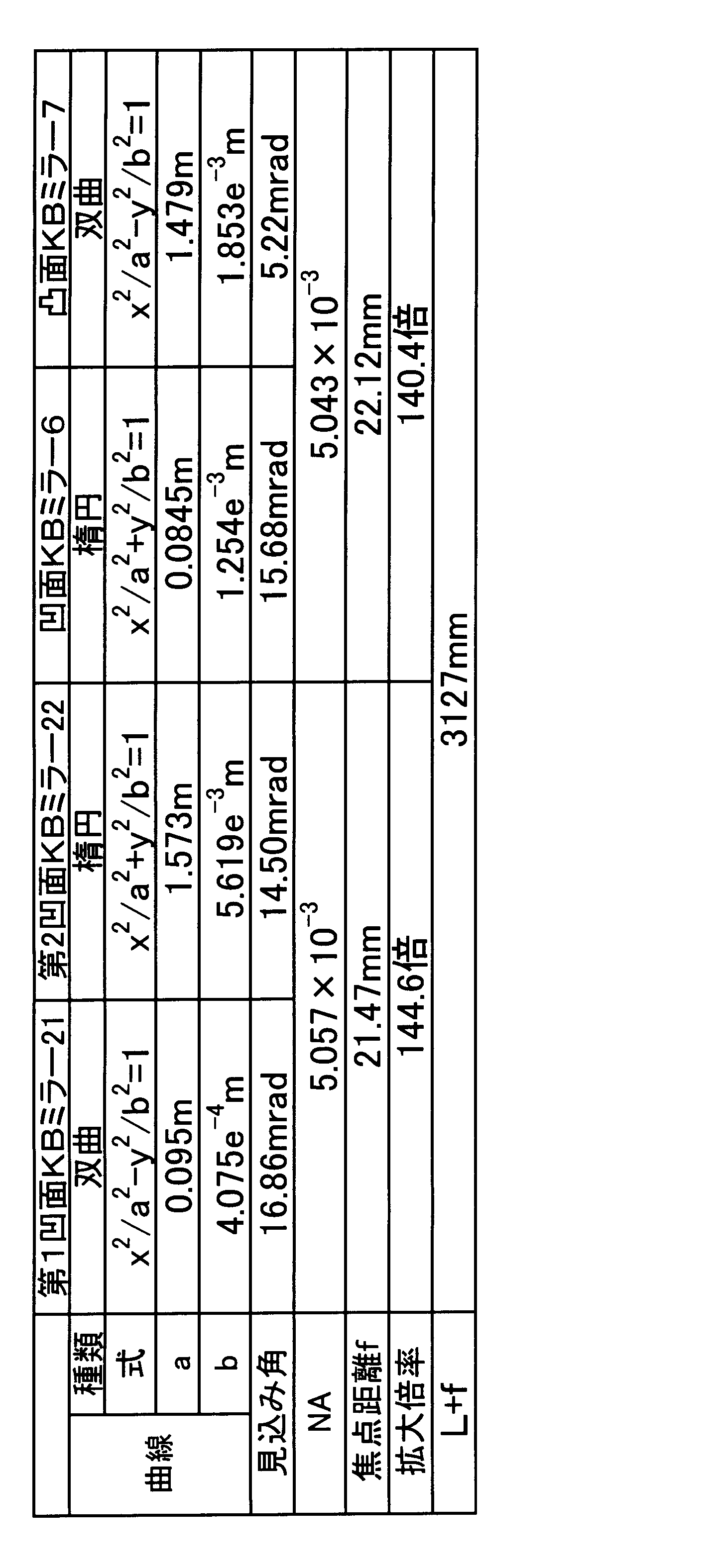
図5~10において、レンズ系の主面の位置は、いずれも点線で表している。
図5(実施の形態3),図6(比較形態1)を比較すると、比較形態1では、レンズの主面の位置が、試料保持部から70mm(図6のf値参照)離れているのに対して、実施の形態3では、レンズの主面の位置が、試料保持部から12mm(図5のf値参照)と、非常に短縮された数値となっている。fの値が小さくなれば、上述の式(1)から分かるように、顕微鏡の拡大倍率Magを同程度とする前提において、Lの値を小さくする設計が可能となる。図6の例では、Lの値が12.6mであるのに対して、図5の例では、Lの値が2.0mと、非常に短縮されている。したがって、X線顕微鏡は、実験室に搬入可能な程度にコンパクトに設計できる。
2 X線
3 試料保持部
4 凹面KBミラー
5 凸面KBミラー
6 凹面KBミラー
7 凸面KBミラー
8 受光部
11 可視光光源
12 可視光線
13 試料保持部
14 可視光凸レンズ
15 可視光凹レンズ
18 受光部
19 凹面KBミラー
20 凹面KBミラー
21 第1の凹面KBミラー
22 第2の凹面KBミラー
Claims (11)
- X線源と、試料保持部と、反射凹面を有するKirkpatrick-Baezミラー(以下、「凹面KBミラー」と記載する)と、反射凸面を有するKirkpatrick-Baezミラー(以下、「凸面KBミラー」と記載する)と、前記試料保持部の位置と結像関係の位置にある受光部とを、順に有するX線顕微鏡。
- 前記凹面KBミラーの前記反射凹面は、楕円形状を含むものであり、前記試料保持部は、該楕円の焦点位置にある請求項1に記載のX線顕微鏡。
- 前記凸面KBミラーの前記反射凸面は、一方曲線と他方曲線を含む双曲線のうち、前記一方曲線を含むものであり、前記受光部は、前記双曲線の焦点のうち他方曲線側の焦点位置にある請求項1または2に記載のX線顕微鏡。
- 前記凸面KBミラーと前記受光部との距離よりも、前記凹面KBミラーと前記受光部との距離が長い請求項1~3のいずれかに記載のX線顕微鏡。
- 前記試料保持部と前記凹面KBミラーとの間に、前記凸面KBミラーと前記凹面KBミラーを含む結像系の主面が存在する請求項1~4のいずれかに記載のX線顕微鏡。
- 前記試料保持部の位置と前記受光部の位置との距離が2.5m以内である請求項1~5のいずれかに記載のX線顕微鏡。
- 前記凸面KBミラーは少なくとも2つ配置されており、前記凹面KBミラーも少なくとも2つ配置されており、
一方の凸面KBミラーの法線と他の凸面KBミラーの法線は互いに非平行であり、
一方の凹面KBミラーの法線と他の凹面KBミラーの法線は互いに非平行である、請求項1~6のいずれかに記載のX線顕微鏡。 - 前記試料保持部と前記凹面KBミラーとの最短距離が6mm以上である請求項1~7のいずれかに記載のX線顕微鏡。
- 前記凸面KBミラーまたは前記凹面KBミラーのうち少なくとも一方は、光軸方向に移動可能に設置されている請求項1~8のいずれかに記載のX線顕微鏡。
- 前記試料保持部と前記凹面KBミラーの間に、第1の凹面KBミラーと第2の凹面KBミラーが配置されており、
前記凹面KBミラーの法線と前記第1の凹面KBミラーの法線は互いに非平行であり、
前記凸面KBミラーの法線と前記第2の凹面KBミラーの法線は互いに非平行である、請求項1~6のいずれかに記載のX線顕微鏡。 - 前記第1の凹面KBミラーは、前記第2の凹面KBミラーよりも前記試料保持部に近く、
前記第1の凹面KBミラーの反射凹面は双曲線を含んでおり、
前記第2の凹面KBミラーの反射凹面は楕円を含んでいる、
請求項10に記載のX線顕微鏡。
Priority Applications (5)
| Application Number | Priority Date | Filing Date | Title |
|---|---|---|---|
| CN201680054724.1A CN108028089B (zh) | 2015-09-25 | 2016-09-23 | X射线显微镜 |
| EP16848678.5A EP3355315B1 (en) | 2015-09-25 | 2016-09-23 | X-ray microscope |
| US15/759,922 US11189392B2 (en) | 2015-09-25 | 2016-09-23 | X-ray microscope |
| KR1020187007977A KR102035949B1 (ko) | 2015-09-25 | 2016-09-23 | X선 현미경 |
| JP2017540926A JP6478433B2 (ja) | 2015-09-25 | 2016-09-23 | X線顕微鏡 |
Applications Claiming Priority (2)
| Application Number | Priority Date | Filing Date | Title |
|---|---|---|---|
| JP2015-188850 | 2015-09-25 | ||
| JP2015188850 | 2015-09-25 |
Publications (1)
| Publication Number | Publication Date |
|---|---|
| WO2017051890A1 true WO2017051890A1 (ja) | 2017-03-30 |
Family
ID=58386722
Family Applications (1)
| Application Number | Title | Priority Date | Filing Date |
|---|---|---|---|
| PCT/JP2016/078070 Ceased WO2017051890A1 (ja) | 2015-09-25 | 2016-09-23 | X線顕微鏡 |
Country Status (6)
| Country | Link |
|---|---|
| US (1) | US11189392B2 (ja) |
| EP (1) | EP3355315B1 (ja) |
| JP (1) | JP6478433B2 (ja) |
| KR (1) | KR102035949B1 (ja) |
| CN (1) | CN108028089B (ja) |
| WO (1) | WO2017051890A1 (ja) |
Cited By (3)
| Publication number | Priority date | Publication date | Assignee | Title |
|---|---|---|---|---|
| CN112740108A (zh) * | 2018-09-20 | 2021-04-30 | Asml荷兰有限公司 | 光学系统、量测设备和相关方法 |
| JP2021117083A (ja) * | 2020-01-24 | 2021-08-10 | キオクシア株式会社 | 撮像装置、画像生成装置及び撮像方法 |
| WO2022092060A1 (ja) * | 2020-11-02 | 2022-05-05 | 国立大学法人大阪大学 | X線光学装置 |
Families Citing this family (46)
| Publication number | Priority date | Publication date | Assignee | Title |
|---|---|---|---|---|
| US20150117599A1 (en) | 2013-10-31 | 2015-04-30 | Sigray, Inc. | X-ray interferometric imaging system |
| US10269528B2 (en) | 2013-09-19 | 2019-04-23 | Sigray, Inc. | Diverging X-ray sources using linear accumulation |
| US10295485B2 (en) | 2013-12-05 | 2019-05-21 | Sigray, Inc. | X-ray transmission spectrometer system |
| US10297359B2 (en) | 2013-09-19 | 2019-05-21 | Sigray, Inc. | X-ray illumination system with multiple target microstructures |
| US10304580B2 (en) | 2013-10-31 | 2019-05-28 | Sigray, Inc. | Talbot X-ray microscope |
| USRE48612E1 (en) | 2013-10-31 | 2021-06-29 | Sigray, Inc. | X-ray interferometric imaging system |
| US10401309B2 (en) | 2014-05-15 | 2019-09-03 | Sigray, Inc. | X-ray techniques using structured illumination |
| US10352880B2 (en) | 2015-04-29 | 2019-07-16 | Sigray, Inc. | Method and apparatus for x-ray microscopy |
| US10295486B2 (en) | 2015-08-18 | 2019-05-21 | Sigray, Inc. | Detector for X-rays with high spatial and high spectral resolution |
| US10649209B2 (en) | 2016-07-08 | 2020-05-12 | Daqri Llc | Optical combiner apparatus |
| US10247683B2 (en) | 2016-12-03 | 2019-04-02 | Sigray, Inc. | Material measurement techniques using multiple X-ray micro-beams |
| US10481678B2 (en) | 2017-01-11 | 2019-11-19 | Daqri Llc | Interface-based modeling and design of three dimensional spaces using two dimensional representations |
| WO2018175570A1 (en) | 2017-03-22 | 2018-09-27 | Sigray, Inc. | Method of performing x-ray spectroscopy and x-ray absorption spectrometer system |
| US10578566B2 (en) | 2018-04-03 | 2020-03-03 | Sigray, Inc. | X-ray emission spectrometer system |
| US10845491B2 (en) | 2018-06-04 | 2020-11-24 | Sigray, Inc. | Energy-resolving x-ray detection system |
| GB2591630B (en) | 2018-07-26 | 2023-05-24 | Sigray Inc | High brightness x-ray reflection source |
| US10656105B2 (en) | 2018-08-06 | 2020-05-19 | Sigray, Inc. | Talbot-lau x-ray source and interferometric system |
| US10962491B2 (en) | 2018-09-04 | 2021-03-30 | Sigray, Inc. | System and method for x-ray fluorescence with filtering |
| DE112019004478T5 (de) | 2018-09-07 | 2021-07-08 | Sigray, Inc. | System und verfahren zur röntgenanalyse mit wählbarer tiefe |
| US11125993B2 (en) * | 2018-12-10 | 2021-09-21 | Facebook Technologies, Llc | Optical hyperfocal reflective systems and methods, and augmented reality and/or virtual reality displays incorporating same |
| EP3894937A4 (en) | 2018-12-10 | 2022-02-16 | Facebook Technologies, LLC. | ADAPTIVE FENCES FOR HYPERFOCAL FENCE DISPLAY (HVP) DEVICES |
| EP3908878A4 (en) | 2019-01-09 | 2022-04-06 | Facebook Technologies, LLC | NON-UNIFORM SUB-PUPIL REFLECTORS AND METHODS IN OPTICAL WAVEGUIDES FOR AR, HMD, AND HUD APPLICATIONS |
| US11143605B2 (en) | 2019-09-03 | 2021-10-12 | Sigray, Inc. | System and method for computed laminography x-ray fluorescence imaging |
| CN111122622B (zh) * | 2019-12-14 | 2021-09-03 | 同济大学 | 一种强度自标定的多通道x射线成像系统和应用方法 |
| US11175243B1 (en) | 2020-02-06 | 2021-11-16 | Sigray, Inc. | X-ray dark-field in-line inspection for semiconductor samples |
| CN111562716B (zh) * | 2020-04-15 | 2022-06-28 | 同济大学 | 一种具有准同轴观测功能的多通道kb显微镜结构 |
| CN115667896B (zh) | 2020-05-18 | 2024-06-21 | 斯格瑞公司 | 使用晶体分析器和多个检测元件的x射线吸收光谱的系统和方法 |
| CN111458868B (zh) * | 2020-05-28 | 2021-08-24 | 重庆工商大学 | 一种基于d-h坐标系的kb镜成像优化方法 |
| JP7640682B2 (ja) | 2020-09-17 | 2025-03-05 | シグレイ、インコーポレイテッド | X線を用いた深さ分解計測および分析のためのシステムおよび方法 |
| JP7572033B2 (ja) | 2020-10-23 | 2024-10-23 | 株式会社リガク | 結像型x線顕微鏡 |
| US12480892B2 (en) | 2020-12-07 | 2025-11-25 | Sigray, Inc. | High throughput 3D x-ray imaging system using a transmission x-ray source |
| KR102927910B1 (ko) | 2020-12-07 | 2026-02-19 | 시그레이, 아이엔씨. | 투과 x-선 소스를 이용한 고처리량 3D x-선 이미징 시스템 |
| JP2023045252A (ja) | 2021-09-21 | 2023-04-03 | キオクシア株式会社 | 半導体記憶装置 |
| WO2023054157A1 (ja) | 2021-10-01 | 2023-04-06 | 国立大学法人東海国立大学機構 | 形状可変ミラーおよびx線装置 |
| JP7717578B2 (ja) | 2021-11-05 | 2025-08-04 | キオクシア株式会社 | 撮像装置、及び、画像生成方法 |
| US11863730B2 (en) | 2021-12-07 | 2024-01-02 | Snap Inc. | Optical waveguide combiner systems and methods |
| US12360067B2 (en) | 2022-03-02 | 2025-07-15 | Sigray, Inc. | X-ray fluorescence system and x-ray source with electrically insulative target material |
| DE112023001408T5 (de) | 2022-03-15 | 2025-02-13 | Sigray, Inc. | System und verfahren für die kompakte laminographie unter verwendung einer mikrofokus-transmissionsröntgenquelle und eines röntgendetektors mit variabler vergrösserung |
| DE112023002079T5 (de) | 2022-05-02 | 2025-02-27 | Sigray, Inc. | Sequenzielles wellenlängendispersives röntgenspektrometer |
| JP2024043971A (ja) | 2022-09-20 | 2024-04-02 | キオクシア株式会社 | 撮像装置、及び、画像生成方法 |
| WO2024173256A1 (en) | 2023-02-16 | 2024-08-22 | Sigray, Inc. | X-ray detector system with at least two stacked flat bragg diffractors |
| US12181423B1 (en) | 2023-09-07 | 2024-12-31 | Sigray, Inc. | Secondary image removal using high resolution x-ray transmission sources |
| WO2025101530A1 (en) | 2023-11-07 | 2025-05-15 | Sigray, Inc. | System and method for x-ray absorption spectroscopy using spectral information from two orthogonal planes |
| WO2025151383A1 (en) | 2024-01-08 | 2025-07-17 | Sigray, Inc. | X-ray analysis system with focused x-ray beam and non-x-ray microscope |
| WO2025155719A1 (en) | 2024-01-18 | 2025-07-24 | Sigray, Inc. | Sequential array of x-ray imaging detectors |
| WO2025174966A1 (en) | 2024-02-15 | 2025-08-21 | Sigray, Inc. | System and method for generating a focused x‑ray beam |
Citations (3)
| Publication number | Priority date | Publication date | Assignee | Title |
|---|---|---|---|---|
| JPH09145899A (ja) * | 1995-11-29 | 1997-06-06 | Nippon Telegr & Teleph Corp <Ntt> | X線集光系 |
| JP2013221874A (ja) * | 2012-04-17 | 2013-10-28 | Osaka Univ | X線光学システム |
| JP2014013169A (ja) * | 2012-07-04 | 2014-01-23 | Jtec Corp | 集光径可変なx線集光システム |
Family Cites Families (9)
| Publication number | Priority date | Publication date | Assignee | Title |
|---|---|---|---|---|
| JPH0443998A (ja) | 1990-06-11 | 1992-02-13 | Hitachi Ltd | X線分析装置,微小部x線回折装置,蛍光x線分析装置及び,x線光電子分析装置 |
| JP3256773B2 (ja) | 1995-03-23 | 2002-02-12 | 日本電信電話株式会社 | X線縮小投影露光装置 |
| JPH08271697A (ja) | 1995-03-28 | 1996-10-18 | Canon Inc | X線顕微鏡用光学装置 |
| JP3167095B2 (ja) * | 1995-07-04 | 2001-05-14 | キヤノン株式会社 | 照明装置とこれを有する露光装置や顕微鏡装置、ならびにデバイス生産方法 |
| JP3284045B2 (ja) * | 1996-04-30 | 2002-05-20 | キヤノン株式会社 | X線光学装置およびデバイス製造方法 |
| JP2000338299A (ja) * | 1999-05-28 | 2000-12-08 | Mitsubishi Electric Corp | X線露光装置、x線露光方法、x線マスク、x線ミラー、シンクロトロン放射装置、シンクロトロン放射方法および半導体装置 |
| DE102005057700A1 (de) * | 2005-11-25 | 2007-06-06 | Axo Dresden Gmbh | Röntgen-Optisches-Element |
| WO2009126868A1 (en) * | 2008-04-11 | 2009-10-15 | Rigaku Innovative Technologies, Inc. | X-ray generator with polycapillary optic |
| CN203069533U (zh) * | 2013-02-05 | 2013-07-17 | 山东大学 | 一种多用途同步辐射相干x射线衍射显微成像装置 |
-
2016
- 2016-09-23 WO PCT/JP2016/078070 patent/WO2017051890A1/ja not_active Ceased
- 2016-09-23 EP EP16848678.5A patent/EP3355315B1/en active Active
- 2016-09-23 CN CN201680054724.1A patent/CN108028089B/zh active Active
- 2016-09-23 JP JP2017540926A patent/JP6478433B2/ja active Active
- 2016-09-23 US US15/759,922 patent/US11189392B2/en active Active
- 2016-09-23 KR KR1020187007977A patent/KR102035949B1/ko active Active
Patent Citations (3)
| Publication number | Priority date | Publication date | Assignee | Title |
|---|---|---|---|---|
| JPH09145899A (ja) * | 1995-11-29 | 1997-06-06 | Nippon Telegr & Teleph Corp <Ntt> | X線集光系 |
| JP2013221874A (ja) * | 2012-04-17 | 2013-10-28 | Osaka Univ | X線光学システム |
| JP2014013169A (ja) * | 2012-07-04 | 2014-01-23 | Jtec Corp | 集光径可変なx線集光システム |
Non-Patent Citations (4)
| Title |
|---|
| JTEC CORP.: "Heisei 22 Nendo Senryakuteki Kiban Gijutsu Kodoka Shien Jigyo 'Hoshako-yo Mirror ni Kansuru Kako Gijutsu no Koseidoka", KANSAI BUREAU OF ECONOMY, TRADE AND INDUSTRY KENKYU KAIHATSU SEIKA HOKOKUSHO, 30 September 2011 (2011-09-30), XP009510065 * |
| KOMEI NAGAI ET AL.: "Imaging Optics for Extreme Ultraviolet Rays", JAPANESE JOURNAL OF OPTICS, vol. 28, no. 12, 2 August 1999 (1999-08-02), pages 16 - 21, XP009509113 * |
| SATOSHI MATSUYAMA ET AL.: "Advanced Kirkpatrick-Baez Mirror Kogakukei o Mochiita Ko Bunkaino Katsu Iroshusa no Nai Ko X-sen Kenbikyo no Kaihatsu", 2014 NENDO THE JAPAN SOCIETY FOR PRECISION ENGINEERING SHUNKI TAIKAI GAKUJUTSU KOENKAI KOEN RONBUNSHU, 1 March 2014 (2014-03-01), pages 1285 - 1286, XP009510063, DOI: 10.11522/pscjspe.2014S.0_1285 * |
| See also references of EP3355315A4 * |
Cited By (7)
| Publication number | Priority date | Publication date | Assignee | Title |
|---|---|---|---|---|
| CN112740108A (zh) * | 2018-09-20 | 2021-04-30 | Asml荷兰有限公司 | 光学系统、量测设备和相关方法 |
| JP2022501584A (ja) * | 2018-09-20 | 2022-01-06 | エーエスエムエル ネザーランズ ビー.ブイ. | 光学系、メトロロジ装置、及び関連の方法 |
| JP2021117083A (ja) * | 2020-01-24 | 2021-08-10 | キオクシア株式会社 | 撮像装置、画像生成装置及び撮像方法 |
| JP7314068B2 (ja) | 2020-01-24 | 2023-07-25 | キオクシア株式会社 | 撮像装置、画像生成装置及び撮像方法 |
| WO2022092060A1 (ja) * | 2020-11-02 | 2022-05-05 | 国立大学法人大阪大学 | X線光学装置 |
| JPWO2022092060A1 (ja) * | 2020-11-02 | 2022-05-05 | ||
| JP7751307B2 (ja) | 2020-11-02 | 2025-10-08 | 国立大学法人大阪大学 | X線光学装置 |
Also Published As
| Publication number | Publication date |
|---|---|
| JPWO2017051890A1 (ja) | 2018-07-19 |
| JP6478433B2 (ja) | 2019-03-06 |
| US11189392B2 (en) | 2021-11-30 |
| KR102035949B1 (ko) | 2019-10-23 |
| KR20180041224A (ko) | 2018-04-23 |
| EP3355315A1 (en) | 2018-08-01 |
| CN108028089A (zh) | 2018-05-11 |
| EP3355315B1 (en) | 2025-05-21 |
| CN108028089B (zh) | 2021-07-06 |
| US20180261352A1 (en) | 2018-09-13 |
| EP3355315A4 (en) | 2019-06-26 |
Similar Documents
| Publication | Publication Date | Title |
|---|---|---|
| JP6478433B2 (ja) | X線顕微鏡 | |
| WO2011144389A1 (en) | Illumination optics for a metrology system for examining an object using euv illumination light and metrology system comprising an illumination optics of this type | |
| JP6048867B2 (ja) | X線光学システム | |
| JP5942190B2 (ja) | 二重反射型x線ミラーを用いた斜入射x線結像光学装置 | |
| CN108051908A (zh) | 一种成像光学系统 | |
| CN101697031A (zh) | 宽谱段、高分辨率变焦距三反射式光学系统 | |
| JP5489034B2 (ja) | 反射型投影光学装置 | |
| US8217353B1 (en) | Non-astigmatic imaging with matched pairs of spherically bent reflectors | |
| TWI866257B (zh) | 用於光罩檢查系統的照明光學單元、光學系統及光罩檢查系統 | |
| JP2025100956A (ja) | 物体を検査するための計測システム用の拡大結像光学ユニット | |
| JP4220170B2 (ja) | X線像拡大装置 | |
| CN104819987B (zh) | 一种超高谱分辨的x射线掠入射显微成像系统 | |
| CN117705722A (zh) | 一种大视场高空间分辨率的一维x射线显微成像光学结构 | |
| JP7751307B2 (ja) | X線光学装置 | |
| CN117352527A (zh) | 一种六通道阵列式Schwarzschild极紫外成像系统 | |
| JP5589555B2 (ja) | X線分析装置 | |
| CN208477092U (zh) | 一种多级联分布式显微ct成像系统 | |
| CN115910421A (zh) | 一种高分辨率高集光效率的x射线显微成像光学结构 | |
| TW202601680A (zh) | 用於產生聚焦x射線束之系統及方法 | |
| CN104681118A (zh) | 一种焦斑可调的二维x射线平面组合折射透镜 | |
| CN103235409A (zh) | 基于光栅衍射的大口径望远镜装置 | |
| Pina et al. | Lobster eye as a collector for water window microscopy | |
| CN110926610A (zh) | 一种自由曲面光谱仪 | |
| Simon et al. | Refractive optical elements and optical system for high energy x-ray microscopy | |
| Hussey et al. | Development of a neutron microscope |
Legal Events
| Date | Code | Title | Description |
|---|---|---|---|
| 121 | Ep: the epo has been informed by wipo that ep was designated in this application |
Ref document number: 16848678 Country of ref document: EP Kind code of ref document: A1 |
|
| ENP | Entry into the national phase |
Ref document number: 2017540926 Country of ref document: JP Kind code of ref document: A |
|
| WWE | Wipo information: entry into national phase |
Ref document number: 15759922 Country of ref document: US |
|
| ENP | Entry into the national phase |
Ref document number: 20187007977 Country of ref document: KR Kind code of ref document: A |
|
| NENP | Non-entry into the national phase |
Ref country code: DE |
|
| WWE | Wipo information: entry into national phase |
Ref document number: 2016848678 Country of ref document: EP |
|
| WWG | Wipo information: grant in national office |
Ref document number: 2016848678 Country of ref document: EP |