WO2017056249A1 - 走行制御方法および走行制御装置 - Google Patents
走行制御方法および走行制御装置 Download PDFInfo
- Publication number
- WO2017056249A1 WO2017056249A1 PCT/JP2015/077785 JP2015077785W WO2017056249A1 WO 2017056249 A1 WO2017056249 A1 WO 2017056249A1 JP 2015077785 W JP2015077785 W JP 2015077785W WO 2017056249 A1 WO2017056249 A1 WO 2017056249A1
- Authority
- WO
- WIPO (PCT)
- Prior art keywords
- boundary
- information
- map
- boundary line
- control method
- Prior art date
- Legal status (The legal status is an assumption and is not a legal conclusion. Google has not performed a legal analysis and makes no representation as to the accuracy of the status listed.)
- Ceased
Links
Images






Classifications
-
- G—PHYSICS
- G01—MEASURING; TESTING
- G01C—MEASURING DISTANCES, LEVELS OR BEARINGS; SURVEYING; NAVIGATION; GYROSCOPIC INSTRUMENTS; PHOTOGRAMMETRY OR VIDEOGRAMMETRY
- G01C21/00—Navigation; Navigational instruments not provided for in groups G01C1/00 - G01C19/00
- G01C21/26—Navigation; Navigational instruments not provided for in groups G01C1/00 - G01C19/00 specially adapted for navigation in a road network
- G01C21/34—Route searching; Route guidance
- G01C21/3407—Route searching; Route guidance specially adapted for specific applications
-
- B—PERFORMING OPERATIONS; TRANSPORTING
- B60—VEHICLES IN GENERAL
- B60W—CONJOINT CONTROL OF VEHICLE SUB-UNITS OF DIFFERENT TYPE OR DIFFERENT FUNCTION; CONTROL SYSTEMS SPECIALLY ADAPTED FOR HYBRID VEHICLES; ROAD VEHICLE DRIVE CONTROL SYSTEMS FOR PURPOSES NOT RELATED TO THE CONTROL OF A PARTICULAR SUB-UNIT
- B60W30/00—Purposes of road vehicle drive control systems not related to the control of a particular sub-unit, e.g. of systems using conjoint control of vehicle sub-units
- B60W30/14—Adaptive cruise control
- B60W30/16—Control of distance between vehicles, e.g. keeping a distance to preceding vehicle
- B60W30/165—Automatically following the path of a preceding lead vehicle, e.g. "electronic tow-bar"
-
- G—PHYSICS
- G01—MEASURING; TESTING
- G01C—MEASURING DISTANCES, LEVELS OR BEARINGS; SURVEYING; NAVIGATION; GYROSCOPIC INSTRUMENTS; PHOTOGRAMMETRY OR VIDEOGRAMMETRY
- G01C21/00—Navigation; Navigational instruments not provided for in groups G01C1/00 - G01C19/00
- G01C21/26—Navigation; Navigational instruments not provided for in groups G01C1/00 - G01C19/00 specially adapted for navigation in a road network
-
- G—PHYSICS
- G01—MEASURING; TESTING
- G01C—MEASURING DISTANCES, LEVELS OR BEARINGS; SURVEYING; NAVIGATION; GYROSCOPIC INSTRUMENTS; PHOTOGRAMMETRY OR VIDEOGRAMMETRY
- G01C21/00—Navigation; Navigational instruments not provided for in groups G01C1/00 - G01C19/00
- G01C21/26—Navigation; Navigational instruments not provided for in groups G01C1/00 - G01C19/00 specially adapted for navigation in a road network
- G01C21/28—Navigation; Navigational instruments not provided for in groups G01C1/00 - G01C19/00 specially adapted for navigation in a road network with correlation of data from several navigational instruments
- G01C21/30—Map- or contour-matching
-
- G—PHYSICS
- G01—MEASURING; TESTING
- G01C—MEASURING DISTANCES, LEVELS OR BEARINGS; SURVEYING; NAVIGATION; GYROSCOPIC INSTRUMENTS; PHOTOGRAMMETRY OR VIDEOGRAMMETRY
- G01C21/00—Navigation; Navigational instruments not provided for in groups G01C1/00 - G01C19/00
- G01C21/26—Navigation; Navigational instruments not provided for in groups G01C1/00 - G01C19/00 specially adapted for navigation in a road network
- G01C21/34—Route searching; Route guidance
- G01C21/36—Input/output arrangements for on-board computers
- G01C21/3602—Input other than that of destination using image analysis, e.g. detection of road signs, lanes, buildings, real preceding vehicles using a camera
-
- G—PHYSICS
- G01—MEASURING; TESTING
- G01C—MEASURING DISTANCES, LEVELS OR BEARINGS; SURVEYING; NAVIGATION; GYROSCOPIC INSTRUMENTS; PHOTOGRAMMETRY OR VIDEOGRAMMETRY
- G01C21/00—Navigation; Navigational instruments not provided for in groups G01C1/00 - G01C19/00
- G01C21/26—Navigation; Navigational instruments not provided for in groups G01C1/00 - G01C19/00 specially adapted for navigation in a road network
- G01C21/34—Route searching; Route guidance
- G01C21/36—Input/output arrangements for on-board computers
- G01C21/3626—Details of the output of route guidance instructions
- G01C21/3658—Lane guidance
-
- G—PHYSICS
- G01—MEASURING; TESTING
- G01C—MEASURING DISTANCES, LEVELS OR BEARINGS; SURVEYING; NAVIGATION; GYROSCOPIC INSTRUMENTS; PHOTOGRAMMETRY OR VIDEOGRAMMETRY
- G01C21/00—Navigation; Navigational instruments not provided for in groups G01C1/00 - G01C19/00
- G01C21/26—Navigation; Navigational instruments not provided for in groups G01C1/00 - G01C19/00 specially adapted for navigation in a road network
- G01C21/34—Route searching; Route guidance
- G01C21/36—Input/output arrangements for on-board computers
- G01C21/3667—Display of a road map
-
- B—PERFORMING OPERATIONS; TRANSPORTING
- B60—VEHICLES IN GENERAL
- B60W—CONJOINT CONTROL OF VEHICLE SUB-UNITS OF DIFFERENT TYPE OR DIFFERENT FUNCTION; CONTROL SYSTEMS SPECIALLY ADAPTED FOR HYBRID VEHICLES; ROAD VEHICLE DRIVE CONTROL SYSTEMS FOR PURPOSES NOT RELATED TO THE CONTROL OF A PARTICULAR SUB-UNIT
- B60W2420/00—Indexing codes relating to the type of sensors based on the principle of their operation
- B60W2420/40—Photo, light or radio wave sensitive means, e.g. infrared sensors
- B60W2420/403—Image sensing, e.g. optical camera
-
- B—PERFORMING OPERATIONS; TRANSPORTING
- B60—VEHICLES IN GENERAL
- B60W—CONJOINT CONTROL OF VEHICLE SUB-UNITS OF DIFFERENT TYPE OR DIFFERENT FUNCTION; CONTROL SYSTEMS SPECIALLY ADAPTED FOR HYBRID VEHICLES; ROAD VEHICLE DRIVE CONTROL SYSTEMS FOR PURPOSES NOT RELATED TO THE CONTROL OF A PARTICULAR SUB-UNIT
- B60W2552/00—Input parameters relating to infrastructure
-
- B—PERFORMING OPERATIONS; TRANSPORTING
- B60—VEHICLES IN GENERAL
- B60W—CONJOINT CONTROL OF VEHICLE SUB-UNITS OF DIFFERENT TYPE OR DIFFERENT FUNCTION; CONTROL SYSTEMS SPECIALLY ADAPTED FOR HYBRID VEHICLES; ROAD VEHICLE DRIVE CONTROL SYSTEMS FOR PURPOSES NOT RELATED TO THE CONTROL OF A PARTICULAR SUB-UNIT
- B60W2552/00—Input parameters relating to infrastructure
- B60W2552/30—Road curve radius
-
- B—PERFORMING OPERATIONS; TRANSPORTING
- B60—VEHICLES IN GENERAL
- B60W—CONJOINT CONTROL OF VEHICLE SUB-UNITS OF DIFFERENT TYPE OR DIFFERENT FUNCTION; CONTROL SYSTEMS SPECIALLY ADAPTED FOR HYBRID VEHICLES; ROAD VEHICLE DRIVE CONTROL SYSTEMS FOR PURPOSES NOT RELATED TO THE CONTROL OF A PARTICULAR SUB-UNIT
- B60W2552/00—Input parameters relating to infrastructure
- B60W2552/53—Road markings, e.g. lane marker or crosswalk
-
- B—PERFORMING OPERATIONS; TRANSPORTING
- B60—VEHICLES IN GENERAL
- B60W—CONJOINT CONTROL OF VEHICLE SUB-UNITS OF DIFFERENT TYPE OR DIFFERENT FUNCTION; CONTROL SYSTEMS SPECIALLY ADAPTED FOR HYBRID VEHICLES; ROAD VEHICLE DRIVE CONTROL SYSTEMS FOR PURPOSES NOT RELATED TO THE CONTROL OF A PARTICULAR SUB-UNIT
- B60W2720/00—Output or target parameters relating to overall vehicle dynamics
- B60W2720/24—Direction of travel
Definitions
- the present invention relates to a travel control method and a travel control device for controlling the travel of a vehicle.
- the problem to be solved by the present invention is to provide a travel control method capable of appropriately outputting lane boundary information.
- the present invention detects lane boundary information of lanes around the host vehicle as real boundary line information from the actual environment around the host vehicle, and the lane boundary of the lane included in the real boundary line information and the map information
- the above-mentioned subject is solved by integrating with the map boundary information which is information of a line, generating integrated boundary information, and outputting the generated integrated boundary information.
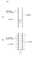
- (A) is a figure for demonstrating the point group of a map boundary line
- (B) is a figure for demonstrating the point group of a sensor boundary line. It is a figure for demonstrating the shift
- the travel control device detects lane boundaries such as lane marks, curbs, and guardrails that actually exist around the host vehicle using sensors mounted on the vehicle (host vehicle). Information on lane boundaries of a planned travel route of the vehicle is detected from the map information. Then, the lane boundary detected by the sensor and the lane boundary possessed by the map information are integrated, and the integrated lane boundary information is output.
- lane boundaries such as lane marks, curbs, and guardrails that actually exist around the host vehicle using sensors mounted on the vehicle (host vehicle).
- Information on lane boundaries of a planned travel route of the vehicle is detected from the map information. Then, the lane boundary detected by the sensor and the lane boundary possessed by the map information are integrated, and the integrated lane boundary information is output.
- FIG. 1 is a diagram showing a configuration of a travel control device 100 according to the present embodiment.
- the travel control device 100 includes a surrounding area detection sensor 110, a vehicle position detection device 120, a map database 130, a presentation device 140, a drive control device 150, and a control device. And 160. These devices are connected by a CAN (Controller Area Network) or another in-vehicle LAN to exchange information with each other.
- CAN Controller Area Network
- the surrounding area detection sensor 110 detects an obstacle (such as another vehicle) or a road sign (such as a lane mark or a curb) existing around the host vehicle.
- a front camera that captures the front of the host vehicle a rear camera that captures the rear of the host vehicle, a side camera that captures the side of the host vehicle, or the like can be used.
- a laser range finder LRF: Laser Range Finder
- LRF Laser Range Finder
- the vehicle position detection device 120 is composed of a GPS unit, a gyro sensor, a vehicle speed sensor, etc., detects radio waves transmitted from a plurality of satellite communications by the GPS unit, and detects position information of a target vehicle (vehicle).
- the current position of the target vehicle is detected on the basis of the position information of the target vehicle acquired periodically, the angle change information acquired from the gyro sensor, and the vehicle speed acquired from the vehicle speed sensor.
- the position information of the target vehicle detected by the vehicle position detection device 120 is output to the control device 160.
- the map database 130 stores map information including road information.
- the road information includes information on lane boundaries that divide the lanes of the road, information on intersections, stop lines, and pedestrian crossings, information on the shape of the road (for example, whether it is a curve or the like), and information on curvature of the road.
- the map database 130 stores the road information in association with the position on the map. Thereby, the travel control device 100 refers to the map database 130 to obtain information on lane boundaries, intersections, stop lines, pedestrian crossings, road shapes, and road curvatures at each position on the planned travel route of the vehicle.
- the lane boundary information if the lane boundary is a lane mark, a curb or a lane mark, the color (for example, white, yellow, etc.) or type (double line, solid line, etc.) of the lane boundary , Dotted lines, etc.) are further included.
- the color for example, white, yellow, etc.
- type double line, solid line, etc.
- the presentation device 140 is, for example, a device such as a display included in a navigation device, a display incorporated in a rearview mirror, a display incorporated in a meter unit, a head-up display projected on a windshield, or a speaker included in an audio device. .
- Drive control device 150 controls the traveling of the host vehicle. For example, when the host vehicle follows the preceding vehicle, the drive control device 150 operates the driving mechanism to realize the acceleration / deceleration and the vehicle speed such that the inter-vehicle distance between the host vehicle and the preceding vehicle becomes a constant distance. (In the case of an engine car, the operation of an internal combustion engine, in the case of an electric car system, the operation of an electric motor, and in the case of a hybrid car, also the torque distribution between the internal combustion engine and the electric motor) When the host vehicle changes lanes or turns right or left at an intersection, the operation of the steering actuator is controlled to control the operation of the wheels to execute turn control of the host vehicle. In addition, as a traveling control method by the drive control device 150, other known methods can also be used.
- the drive control device 150 controls the traveling of the own vehicle based on the information of the lane boundary line outputted by the control device 160 described later. For example, the drive control device 150 travels in the lane of the planned travel route by grasping the lane of the planned travel route of the own vehicle based on the information of the lane boundary line output by the control device 160. Thus, the traveling of the host vehicle can be controlled. In addition, the drive control device 150 grasps a position (for example, a right turn lane, an intersection, a crosswalk side, etc.) on the map where the own vehicle travels based on the information of the lane boundary line output by the control device 160. Therefore, it is possible to appropriately determine the behavior of the vehicle (for example, stop, acceleration, right turn, left turn, etc.).
- a position for example, a right turn lane, an intersection, a crosswalk side, etc.
- Control device 160 is a ROM (Read Only Memory) storing a program for controlling the traveling of the host vehicle, a CPU (Central Processing Unit) executing a program stored in this ROM, and an accessible storage device. It consists of a functional RAM (Random Access Memory). Note that as an operation circuit, a micro processing unit (MPU), a digital signal processor (DSP), an application specific integrated circuit (ASIC), a field programmable gate array (FPGA), etc., instead of or in addition to a central processing unit (CPU) Can be used.
- MPU micro processing unit
- DSP digital signal processor
- ASIC application specific integrated circuit
- FPGA field programmable gate array
- the control device 160 executes a program stored in the ROM by the CPU to search for a planned traveling route of the host vehicle, and a map boundary detection function for detecting a lane boundary based on the map information. And a sensor boundary detection function of detecting a lane boundary based on the detection result by the surrounding detection sensor 110, a lane boundary detected based on the map information, and a detection based on the detection result of the surrounding detection sensor 110 A boundary integration function that integrates the lane boundaries and the output function that outputs integrated lane boundary information is realized.
- each function of the control device 160 will be described.
- the route search function of the control device 160 generates a planned travel route of the own vehicle from the current position of the own vehicle and the destination.
- the route search function can acquire the position of the host vehicle from the host vehicle position detection device 120 and can acquire the destination input by the driver from an input device (not shown).
- the route search function can search for a planned travel route using a known method.
- the map boundary detection function of the controller 160 detects the lane boundary of the lane including the own lane based on the map information stored in the map database 130.
- a lane boundary is adjacent to a lane, such as a lane mark (a solid, double or broken line drawn with white, orange or yellow on the road to divide the lane), a curb or a guardrail, etc. It is a line which defines the boundary of a lane or a lane and a road shoulder.
- the map information stored in the map database 130 includes information on the boundary of each lane, and the map boundary detection function refers to the map information to map the lane boundary of the lane including the own lane.
- the lane boundary detected by the map boundary detection function is not limited to the lane around the host vehicle, and, for example, the lane boundary of the lane in the planned travel route of the host vehicle can also be detected.
- lane boundaries detected by the map boundary detection function will be described as map boundaries.
- the sensor boundary detection function of the controller 160 detects the lane boundary of the lane around the host vehicle based on the detection result of the surrounding detection sensor 110. For example, the sensor boundary detection function captures lane marks, curbs, and guardrails present around the host vehicle with a front camera, a side camera, or a rear camera, and analyzes the captured image to analyze the image of the host vehicle. Lane boundaries of surrounding lanes can be detected. In addition, the sensor boundary detection function detects the brightness of the road surface or lane mark around the host vehicle with the laser range finder, or detects the convex part of the curb by distance measurement, so that the lane boundary of the lane around the host vehicle The line can be detected.
- the range in which a lane mark, a curb, a guardrail, etc. can be detected with high accuracy by the camera is approximately several tens of meters from the camera.
- a laser range finder can also be used to identify lane marks and curbs.
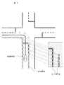
- the range in which the lane boundary can be detected by the sensor boundary detection function is, as shown in FIG. 2, a range of several tens of meters from the host vehicle.
- FIG. 2 is a figure for demonstrating the detection range of the surrounding detection sensor 110. As shown in FIG. Also, in the following, a lane boundary detected by the sensor boundary detection function will be described as a sensor boundary.
- the map boundary detection function Map boundaries can be detected as map boundaries represented by point clouds.
- the map boundary detection function can detect each of the left and right map boundaries in the traveling direction of the host vehicle as map boundaries represented by a point group.
- the map boundary detection function detects the map boundary as a map boundary expressed by a function. Can.
- the sensor boundary detection function can detect a sensor boundary as a sensor boundary represented by a point group.
- the sensor boundary detection function can detect each of the left and right sensor boundaries in the traveling direction of the host vehicle as sensor boundary lines represented by a point group.
- the sensor boundary detection function can also detect a sensor boundary as a function having a particular order. For example, when the sensor boundary detected by the ambient detection sensor 110 is represented by a point group, the sensor boundary detection function fits the sensor boundary with a function having a specific order, The function fitted to the sensor boundary can be detected as a sensor boundary expressed as a function.
- FIG. 3A is a diagram for explaining a map boundary line expressed by a point group
- FIG. 3B is a diagram for explaining a sensor boundary line expressed by a point group. is there.
- the border integration function of the controller 160 integrates the map border detected by the map border detection function and the sensor border detected by the sensor border detection function, and includes the lane in which the vehicle travels. Generate lane boundaries for the lanes.
- the range in which the sensor boundary detection function can detect the lane boundary (sensor boundary) with high accuracy is the range around the host vehicle, and the lane boundary is the further away from the host vehicle
- the detection accuracy of (sensor boundary line) is lowered. Therefore, in the present embodiment, the area outside the detection range where the lane boundary can be detected by the sensor boundary detection function is complemented using the lane boundary (map boundary) detected by the map boundary detection function.
- the detection range of the surrounding detection sensor 110 is superimposed on the position of the own vehicle detected by the own vehicle position detection device 120, and the area outside the sensor boundary line based on the detection result of the surrounding detection sensor 110 is , It shows a state of being supplemented by the map border based on the map information.
- a map boundary based on map information and a sensor boundary based on the detection result of the surrounding detection sensor 110 Matches and there is no large deviation.
- the boundary integration function is detected by the surrounding detection sensor 110 so that the sensor boundary detected by the surrounding detection sensor 110 matches the map boundary based on the map information.
- Sensor boundaries are complemented by map boundaries based on map information.
- the boundary integration function first determines the degree of coincidence between the sensor boundary detected by the surrounding detection sensor 110 and the map boundary based on the map information by an ICP (Iterative Closest Point) method.
- ICP Intelligent Closest Point
- the alignment between “a point group indicating a sensor boundary detected by the surrounding detection sensor 110” and “a point group indicating a map boundary possessed by map information” is performed based on the least squares method. is there.
- FIG. 5 is a diagram showing an example of a method of integrating lane boundaries by the boundary integration function.
- a white circle indicates a point cloud indicating a map boundary line
- a gray circle indicates a sensor boundary line.
- the boundary integration function focuses on a portion of the intersection where the curbs are disposed substantially at right angles to “show the sensor boundary.
- the alignment between the point cloud and the point cloud indicating the map boundary can be performed. In this way, based on the characteristic part of the road (generally at right angles in the example shown in FIG. 5), the “point group indicating the sensor boundary line” and the “point group indicating the map boundary line” are aligned.
- the borderline integration function can detect a portion of the map borderline that is highly coincident with the sensor borderline. Then, by performing the alignment in this way, even if the own vehicle has been detected at a position different from the actual position, as shown in FIG. 4, temporarily, due to the detection error of the own vehicle position detection device 120.
- the host vehicle can obtain an appropriate position on the map, and the lane boundary line of the lane around the host vehicle can be appropriately grasped.
- the map boundary line and the sensor boundary line may be represented by a point group or may be represented by a function, as shown in FIGS. 3 (A) and 3 (B).
- ICP in the above-described ICP, although it is possible to collate the map boundary expressed by a point group with the sensor boundary, it is not possible to collate the map boundary expressed by a function with the sensor boundary. Therefore, when map boundaries or sensor boundaries are detected as functions, map boundaries and sensor boundaries expressed as functions are converted into map boundaries and sensor boundaries expressed as point clouds. There is a need. Also, in this case, conversion is performed so that the information of the map boundary and the sensor boundary expressed by the function and the information of the map boundary and the sensor boundary expressed by the point group fall within a predetermined error range.
- the boundary integration function reduces the distance between the position coordinates of each point of the map boundary and the sensor boundary expressed by the point group as the curvature of the road is larger, and as the curvature of the road is smaller, Increase the distance between the position coordinates of each point of the represented map boundary and sensor boundary.
- the boundary integration function collates the sensor boundary with the map boundary based on the position of the vehicle or the planned traveling route of the vehicle. For example, the boundary integration function collates a portion of the map boundary near the position of the vehicle detected by the position detection device 120 with the sensor boundary, and if it does not match, the position of the vehicle gradually increases. The part of the map border located at a position far from the point is compared with the sensor border. Alternatively, the boundary integration function collates the map boundary with the sensor boundary along the planned travel route of the host vehicle. Thereby, the map boundary and the sensor boundary can be efficiently collated.
- FIG. 6 is a flowchart showing a traveling control process according to the first embodiment.
- step S101 the current position of the vehicle is detected by the route search function of the control device 160.
- step S102 the route search function of the control device 160 searches for a planned travel route.
- the route search function searches for a planned travel route from the current position of the host vehicle to the destination based on the position information of the host vehicle acquired in step S101.
- the route search function searches for a planned traveling route of the own vehicle based on not only the road on which the own vehicle travels but also the lane in which the own vehicle travels.
- the route search function can determine the planned travel route of the host vehicle at the lane level by a method using graph search theory such as Dijkstra's algorithm or A * algorithm.
- the map database 130 stores information of links and nodes for each lane in the map information.
- the weight according to the traveling distance and the road condition in each lane is preset (for example, the longer the distance, the worse the road condition, the larger the weight of the link).
- the route search function identifies a lane suitable for the travel route to the destination, and corrects the link weight of the identified lane. For example, if it is necessary to make a right turn to reach a destination, correction may be made to reduce the weight of the link in the right turn lane.
- the route search function uses a graph search theory such as the Dijkstra method or A * algorithm to determine a lane level route that minimizes the total sum of the link weights of the lane passing from the current position of the host vehicle to the destination. It can be searched as a planned travel route.
- the map boundary detection function of the control device 160 detects the map boundary.
- information of lane boundaries of each lane is stored in the map database 130 in association with the position on the map.
- the map boundary detection function can acquire lane boundary information of the lane on the planned traveling route of the host vehicle, and can grasp that curb B1 exists on the left side in the traveling direction . Then, the map boundary detection function can detect the curb B1 on the left in the direction of travel as the map boundary on the left side in the direction of travel.
- the map boundary detection function can grasp that the white line A2 exists on the right side in the traveling direction, and can detect the white line A2 on the right side in the traveling direction as a map boundary on the right side in the traveling direction.
- the map boundary detection function can detect the curb B2 and the white line A1 as a map boundary in front of the planned travel route of the host vehicle.
- FIG. 7 is a view showing an example of the map boundary line.
- the map boundary detection function can detect the map boundary A3 on the right side in the traveling direction even in the intersection where the host vehicle turns left.
- step S104 the sensor boundary detection function of the control device 160 detects the sensor boundary based on the detection result of the surrounding detection sensor 110.
- the detection range of the sensor boundary line by the surrounding detection sensor 110 is a range within a predetermined distance (for example, several tens of meters) from the host vehicle, that is, a range around the host vehicle.
- step S105 the map boundary line detected in step S103 and the sensor boundary line detected in step S104 are collated by the boundary line integration function of the control device 160. Then, in the subsequent step S106, it is judged by the boundary integration function whether or not there is a portion that matches the sensor boundary within the map boundary based on the comparison result in step S105. If there is a portion in the map boundary that matches the sensor boundary, the process proceeds to step S107. On the other hand, when there is no portion in the map boundary that matches the sensor boundary, the traveling control process shown in FIG. 6 is ended. For example, in the example illustrated in FIG. 5, since there is a portion in the map boundary that matches the sensor boundary, the process proceeds to step S107.
- the case of “matching” is not limited to the case where a portion exactly the same as the sensor boundary exists in the map boundary, and the degree of coincidence with the sensor boundary in the map boundary is a predetermined value or more. It also includes the case where a part exists. Further, the predetermined value can be appropriately set by design or the like.
- step S107 and subsequent steps processing is performed using map boundaries and sensor boundaries represented by point clouds.
- the map boundary expressed by a point cloud and the sensor boundary expressed by a point cloud are, as shown in FIG. 5, the map boundary and the sensor boundary, and the position of each point on the map boundary and the sensor boundary. It is expressed by coordinates.
- the map boundary line and the sensor boundary line may be detected as the boundary line expressed by a point group in steps S103 and S104. In some cases, map boundaries and sensor boundaries may be detected as a function with a particular order.
- the map boundary line and sensor boundary line expressed by the point group are detected in steps S103 and S104, the map boundary line and sensor boundary line expressed by the point group are used as they are, and the step is performed.
- the process after S107 is performed.
- the map boundary line expressed by the function and the sensor boundary line are detected in steps S103 and S104, the map boundary line and the sensor boundary line expressed by the function are map boundaries expressed by the point group. Converting into a line and a sensor boundary line, the process after step S107 is performed.
- the map boundary line expressed by a function and the sensor boundary line are converted to the map boundary line and the sensor boundary line expressed by a point group
- the map boundary line expressed by a function and the sensor boundary line and point group are expressed It is possible to appropriately change the intervals for detecting the position coordinates of each point on the map boundary expressed as a function and the sensor boundary so that the error between the detected map boundary and the sensor boundary is not more than a predetermined value .
- the road shape is substantially straight
- position coordinates of each point of the map boundary and the sensor boundary are detected at equal intervals, and if the shape of the road is not straight, the larger the curvature of the road, the map
- the distance between the position coordinates of each point of the boundary line and the sensor boundary line can be shortened.
- the information on the map boundary and the sensor boundary is simplified by detecting the position coordinates of each point of the map boundary and the sensor boundary at equal intervals.
- the map boundary line and the sensor boundary line can be made more accurate by shortening the distance between the position coordinates of the map boundary line and the sensor boundary line as the curvature of the road increases. Can be detected.
- the map boundary line and the sensor boundary line are different than when the speed limit of the road or the speed of the host vehicle is less than the predetermined speed.
- the interval between the position coordinates of the points can be configured to be long. Also in this case, the map boundary and the sensor boundary can be detected with high accuracy in accordance with the traveling state of the host vehicle.
- the boundary integration function detects a portion of the map boundary that matches the sensor boundary (hereinafter, also referred to as a matching portion). For example, the boundary integration function collates the map boundary with the sensor boundary in a certain range based on the position of the vehicle on the map or the planned travel route of the vehicle, and the sensor boundary is most closely matched with the sensor boundary. Portions of high map boundaries can be detected as matched portions. Further, the boundary integration function may be configured to detect a portion of the map boundary which is first detected and whose degree of coincidence with the sensor boundary is equal to or more than a predetermined value as a coincidence portion.
- the boundary integration function is a portion of the map boundary which is on the traveling direction side of the own vehicle than the current position of the own vehicle, and the match extracted in step S107.
- the portion of the map border that continues from the portion is determined as the map integration target portion.
- FIG. 8 shows an example of the matching part and the map integration target part.
- the matching portion of the map boundary is indicated by a gray solid line and a gray circle (point cloud)
- the map target integrated portion of the map boundary is indicated by a black solid line (thick line) and a white circle. Marks (point groups) are shown, and the remaining map boundaries are indicated by black solid lines (thin lines) and black circles (point groups).
- step S108 the boundary integration function detects points closest to the vehicle among the determined map integration target parts as target points S1 and S2. Then, the boundary integration function stores the position coordinates of the target points S1 and S2 in the RAM of the control device 160. For example, in the example shown in FIG. 9, the boundary integration function detects the target points S1 and S2 closest to the host vehicle, and stores the position coordinates (x1Lm, y1Lm) and (x1Rm, y1Rm) of the target points S1 and S2. Do.
- step S109 a process of adding the position coordinates of each point of the sensor boundary detected in step S104 to the array is performed by the boundary integration function.
- the boundary integration function For example, in the present embodiment, an empty array (R_bound [], L_bound []) corresponding to the lane boundary on the right side in the traveling direction and the lane boundary on the left side in the traveling direction is stored in advance in the RAM of the controller 160. . Then, as shown in FIG. 9 and Equations 1 and 2 below, the boundary integration function proceeds in the order from the point closer to the vehicle among the sensor boundaries, the position coordinates of each point of the sensor boundary on the right in the direction of travel, The position coordinates of each point of the sensor boundary on the left side of the direction are respectively added to the corresponding array.
- position coordinates of seven points (x1L, y1L) to (x7L, x7L) are sequentially added to the array on the left side in the traveling direction from the position coordinates closer to the host vehicle.
- position coordinates of four points (x1R, y1R) to (x4R, x4R) are added to the array on the right side in the traveling direction in order from position coordinates closer to the host vehicle.
- R_bound [i] ⁇ (x1R, y1R), (x2R, y2R), ..., (xMR, yMR) ⁇
- L_bound [i] ⁇ (x1L, y1L), (x2L, y2L), ..., (xNL, yNL) ⁇
- M is the number of position coordinates of each point of the sensor boundary on the right side of the traveling direction expressed by a point group, and is 4 in the example shown in FIG. The same applies to 3).
- N is the number of position coordinates of each point of the sensor boundary on the left in the traveling direction represented by a point group, and is 7 in the example shown in FIG. The same applies to 4).
- the boundary integration function further adds the position coordinates of each point of the map integration target portion determined in step S108 to the array obtained by adding the position coordinates of each point of the sensor boundary in step S109. Specifically, the boundary integration function determines the map integration target portion determined in step S108 in the array (R_bound [i], L_bound [i]) to which the position coordinates of each point of the sensor boundary are added in step S109. The position coordinates of each point of are added in order from the point closer to the vehicle.
- the array (R_bound [i], L_bound [i]) adds position coordinates of each point of the sensor boundary line in order of proximity from the host vehicle and then adds The position coordinates of each point of the map integration target portion are added in order of proximity to the host vehicle.
- R_bound [i] ⁇ (x1R, y1R), (x2R, y2R), ..., (xMR, yMR), (x1Rm, y1Rm), (x2Rm, y2Rm), ..., (xORm, yORm) ⁇ ...
- L_bound [i] ⁇ (x1L, y1L), (x2L, y2L), ..., (xNL, yNL), (x1Lm, y1Lm), (x2Lm, y2Lm), ..., (xPLm, yPLm) ⁇ ...
- O is the number of position coordinates of the map integration target portion on the right side of the traveling direction expressed by a point group, and is 8 (or more) in the example shown in FIG.
- N is the number of position coordinates of each point of the map integration target portion on the left in the traveling direction expressed by a point group, and in the example shown in FIG. It becomes.
- the borderline integration function adds the location coordinates of each point of the sensor borderline in order of proximity from the host vehicle, and then adds the location coordinates of each point of the map integration target portion in order of proximity to the host vehicle.
- the lane boundary integrated in step S110 will be described as an integrated boundary.
- step S111 the output function of the control device 160 outputs the information on the integrated boundary generated in step S110.
- the output function outputs integrated boundary information to the drive control device 150.
- the drive control device 150 controls the drive of the host vehicle based on the information on the integrated boundary line output in step S111.
- step S111 when outputting the information on the integrated boundary, the output function of the control device 160 outputs the information on the integrated boundary in the format used by the drive control device 150.
- the output function is a function having a specific order with respect to the integrated boundary represented by a point group. Fitting, the integrated boundary represented by the point group can be converted into an integrated boundary represented by the function, and the information of the integrated boundary represented by the function can be output to the drive control device 150 .
- the position coordinates of each point of the integrated boundary are equal
- the distance between the position coordinates of each point of the integrated boundary can be shortened as the curvature of the road increases.
- the distance between the position coordinates of each point of the integrated boundary can be determined based on the speed limit of the road and the speed of the host vehicle.
- the lane boundary around the host vehicle is detected as the sensor boundary based on the detection result of the surrounding detection sensor 110, and the lane boundary of the planned travel route of the host vehicle is determined from the map information. Detect as map boundaries. Then, the map boundary line and the sensor boundary line are collated, and the sensor boundary line and the map boundary line are integrated such that the range outside the sensor boundary line is complemented by the map boundary line. Thereby, even if a detection error occurs in the vehicle position detection device 120, it is possible to determine the action plan and the planned route based on the sensor boundary line actually detected by the surrounding detection sensor 110 around the own vehicle. Since it can, according to the actual driving
- the surrounding area detection sensor 110 can not detect the lane boundary line with high accuracy in a range distant from the host vehicle by a predetermined distance (for example, several tens of meters) or more.
- a predetermined distance for example, several tens of meters
- the traveling of the vehicle is controlled using only the information of the map boundary, if a detection error of the vehicle position detection device 110 occurs, the vehicle travels in a lane different from the lane on which the vehicle actually travels. Under the above conditions, travel control of the host vehicle may be performed, so that travel of the host vehicle may not be properly controlled.
- the road ahead of the surroundings of the vehicle has any road shape, and the position of the vehicle on the map Since it can not be determined whether the vehicle is traveling, there are cases where it is not possible to control the traveling of the vehicle according to the future traveling environment of the vehicle.
- the sensor boundary line and the map boundary line are integrated and output, so that the vehicle can appropriately travel according to the actual traveling environment of the vehicle around the vehicle. While being able to control, it is possible to control the traveling of the vehicle appropriately according to the traveling environment in the future.
- the map boundary line represented by the point group and the sensor boundary line are integrated to generate an integrated boundary line represented by the point group, and the integrated boundary line represented by the point group is output. .
- the boundary line information represented by the point group is used in action determination and travel control, the information of the integrated boundary line represented by the point group can be used as it is.
- the integrated boundary represented by the point group is represented by the function. Convert to and output an integrated boundary expressed as a function. As a result, even when an error occurs in part of the detection result of the surrounding detection sensor 110, a smooth integrated boundary can be output.
- the travel control device 100 according to the second embodiment has the same configuration as the travel control device 100 of the first embodiment, and is the same as the first embodiment except that it operates as described below.
- the boundary integration function of the control device 160 is detected by the ambient detection sensor 110 based on the curvature of a road, the continuity of curves, etc. when integrating the sensor boundary and the map boundary. Determine the reliability of the sensor boundary. Then, as the reliability of the sensor boundary is higher, the range of the sensor boundary integrated with the map boundary is made wider in the traveling direction of the vehicle, while the lower the reliability of the sensor boundary is, the map boundary and The range of sensor boundaries to be integrated is narrowed in the direction opposite to the traveling direction of the vehicle.
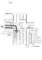
- the boundary line integration function of the control device 160 identifies the lane number of the lane in which the host vehicle travels based on the detection result of the surrounding area detection sensor 110. For example, as shown in FIG. 10, the borderline integration function assigns lane numbers sequentially from 1 to the center side from the shoulder side of the road. Then, the boundary line integration function causes the own vehicle to travel by determining whether or not there is an adjacent lane adjacent to the lane where the own vehicle travels, and whether the lane where the own vehicle travels is the closest lane to the road end. Identify the lane number that corresponds to the lane. For example, as shown in FIG.
- the adjacent lane does not exist on the left side in the traveling direction of the lane in which the host vehicle travels, and the adjacent lane exists on the right side in the traveling direction of the lane in which the host vehicle travels.
- the boundary line integration function can specify the lane number of the lane in which the host vehicle travels as the lane number “1” on the most shoulder side.
- FIG. 10 is a diagram for explaining a method of specifying the lane number of the lane in which the host vehicle travels.
- the lane on which the vehicle travels when the vehicle is traveling on one lane on two ways and the curb or guardrail is detected by the surrounding area detection sensor 110, the lane on which the vehicle travels.
- the lane number can be specified as lane number 1 of the lane on the shoulder side of the two-way one-way lane.
- the boundary line integration function is not illustrated, the own vehicle is traveling on a straight line of two lanes on one way, and the surrounding area detection sensor 110 separates the central lane between the opposite lane and the lane where the own vehicle travels.
- the lane number of the lane in which the host vehicle travels can be identified as the lane number 2 of the lane on the center side of the two-way one-way lane.
- the boundary integration function collates the sensor boundary with the map boundary along the lane of the identified lane number. For example, in the example shown in FIG. 10, since it is specified that the host vehicle is traveling in the lane with lane number "1", the borderline integration function is performed for the lane number of lane number "1" possessed by the map information.
- the lane boundary is matched with the sensor boundary. Thereby, even if at least one of the detection accuracy of the position of the vehicle by the vehicle position detection device 120, the accuracy of the detection result by the surrounding detection sensor 110, and the accuracy of the map information is low, according to the traveling condition of the vehicle. , Sensor boundaries and map boundaries can be properly integrated.
- FIG. 11 is a flowchart showing a traveling control process according to the second embodiment.
- steps S201 to S204 as in steps S101 to S104 in the first embodiment, the current position of the vehicle is detected (step S201), and a travel planned route from the current position to the destination is searched (step S202). ). Then, the detection of the map boundary is performed from the map information (step S203), and the detection of the sensor boundary is performed based on the detection result of the surrounding detection sensor 110 (step S204).
- the map boundary detection function is not limited to the lane in which the host vehicle is traveling, but the lane in which the host vehicle can travel (for example, in the example shown in FIG. 10, the lane with lane number 1 in which the host vehicle is traveling and Lane boundaries of the lane number 2 adjacent to it) are detected as map boundaries. That is, in the example shown in FIG. 10, it can be predicted that the host vehicle can turn left at the intersection from the planned travel route of the host vehicle, and it is determined that the host vehicle is traveling in the lane of lane number 1 that can turn left at the intersection. can do.
- the lane boundary of the lane in which the host vehicle can travel is detected as a map boundary line.
- step S205 the map boundary line and the sensor boundary line are collated by the boundary line integration function.
- the position detection accuracy of the vehicle position detection device 120, the detection accuracy of the surrounding detection sensor 110, or the accuracy of the information of the lane boundary possessed by the map information is less than a predetermined value. Even if the map boundaries are moved, shrunk, enlarged, or rotated relative to the sensor boundaries, so that the sensor boundaries and the map boundaries can be properly integrated, the map boundaries and the sensor boundaries Match with.
- the boundary line integration function determines whether or not there is an adjacent lane adjacent to the lane in which the host vehicle is traveling, and the lane in which the host vehicle is traveling is closest to the roadside.
- the lane number of the lane in which the host vehicle travels is specified from the presence or absence of the vehicle and the type of the lane boundary of the lane in which the host vehicle travels.
- the border integration function moves the map border with respect to the sensor border so as to collate the sensor border with the lane border of the lane in which the lane number is specified among the map border, Reduce, enlarge, or rotate.
- FIG. 12 shows the map boundary line and the sensor boundary line when the position detection accuracy of the own vehicle position detection device 120, the detection accuracy of the surrounding area detection sensor 110, or the information of the lane boundary line possessed by the map information is low. It is a figure for demonstrating.
- the boundary integration function can detect a portion of the map boundary that matches the sensor boundary by moving, reducing, enlarging, or rotating the map boundary with respect to the sensor boundary.
- the conditions of moving, shrinking, enlarging, or rotating the map boundary are stored in the RAM of the control device 160.
- step S206 as in step S106 of the first embodiment, it is determined whether or not there is a portion in the map boundary that matches the sensor boundary, and if there is a portion that matches, the step is performed. The process proceeds to S207, and when there is no matching part, the traveling control process shown in FIG. 11 is ended.
- step S207 the reliability of the detection result of the surrounding detection sensor 110 is determined by the boundary integration function.
- the detection of the surrounding detection sensor 110 is performed as compared with the case where the curvature of the road is a curve having a predetermined value or more. The errors tend to be small. Therefore, when the curvature of the road is less than a predetermined value, the boundary integration function determines the reliability of the detection result of the surrounding area detection sensor 110 to be higher than when the curvature of the road is equal to or more than the predetermined value.
- the boundary line integration function can be configured to determine the reliability of the detection result of the surrounding area detection sensor 110 to be lower as the curvature of the road is larger. Furthermore, when the road is a curve, when two or more curves are continuous, the detection error of the surrounding area detection sensor 110 tends to be larger than when the curves are not continuous. Therefore, the boundary line integration function may be configured to determine the reliability of the detection result of the surrounding area detection sensor 110 to be lower when two or more curves are continuous than when the curves are not continuous. . Furthermore, the boundary line integration function determines the reliability of the detection result of the environment detection sensor 110 to be lower when the curves having different curvatures are continuous as compared with the case where the curves having similar curvatures are continuous. It can also be done.
- step S208 based on the reliability of the detection result of the surrounding detection sensor 110 determined in step S207 by the boundary integration function, a boundary portion to be integrated with the map boundary among the sensor boundaries (hereinafter, sensor integration target The decision of the part is made.
- FIG. 13 is a diagram showing an example of the correspondence between the reliability of the detection result of the surrounding area detection sensor 110 and the size of the sensor integration target portion (the distance from the host vehicle of the sensor integration target portion).
- the boundary integration function enlarges the sensor integration target part (the distance from the host vehicle of the sensor integration target part increases) as the reliability of the detection result of the surrounding area detection sensor 110 increases.
- the boundary integration function makes the sensor integration target portion smaller (shortens the distance from the host vehicle of the sensor integration target portion) as the reliability of the detection result of the surrounding area detection sensor 110 is lower.
- FIGS. 14 and 15 are diagrams for explaining the method of integrating the sensor integration target portion and the map integration target portion.
- the boundary integration function deducts a portion of the map boundary which is on the travel direction side of the vehicle relative to the current position of the vehicle and corresponds to the sensor integration target portion detected in step S208. Parts are detected as map integration target parts.
- the boundary integration function specifies, as target points S1 and S2, points on the map boundary corresponding to a point farthest from the vehicle in the sensor integration target portion.
- the borderline integration function can detect a portion of the map borderline in the traveling direction side of the subject vehicle (the side away from the subject vehicle) than the target points S1 and S2 as a map integration target part.
- step S210 the position coordinates of each point of the sensor integration target portion determined in step S208 are stored in advance in the RAM of the control device 160 by the boundary integration function as shown in the following equations (5) and (6) Processing is performed to add to the empty array.
- R_bound [i] ⁇ (x1R, y1R), (x2R, y2R),..., (XMR, yMR) ⁇
- L_bound [i] ⁇ (x1L, y1L), (x2L, y2L), ..., (xNL, yNL) ⁇ (6)
- M is the number of position coordinates of each position of the sensor integration target portion on the right side in the traveling direction represented by a point group, and is 4 in the example shown in FIG.
- N is the number of position coordinates of each position of the sensor integration target portion on the left in the traveling direction expressed by a point group, and is 7 in the example shown in FIG. In the example, it is 2 (the following equation (8) is also the same).
- step S211 the position coordinates of each point of the map integration target portion determined in step S209 is the sensor integration target in step S210 by the boundary integration function. It is added to the array which added the position coordinates of each point of the part.
- R_bound [i] ⁇ (x1R, y1R), (x2R, y2R), ..., (xMR, yMR), (x1Rm, y1Rm), (x2Rm, y2Rm), ..., (xORm, yORm) ⁇ ...
- L_bound [i] ⁇ (x1L, y1L), (x2L, y2L), ..., (xNL, yNL), (x1Lm, y1Lm), (x2Lm, y2Lm), ..., (xPLm, yPLm) ⁇ ...
- O is the number of position coordinates of the map integration target portion on the right side of the traveling direction expressed by a point group, and is 8 (or more) in the example shown in FIG. In the example shown in, it is 10 (or more).
- N is the number of position coordinates of each point of the map integration target portion on the left in the traveling direction expressed by a point group, and is 4 (or more) in the example shown in FIG. , 9 (or more) in the example shown in FIG.
- the position coordinates of each point of the sensor integration target portion are added in order of proximity from the host vehicle
- the position coordinates of each point of the map integration target portion are added in order of proximity to the host vehicle.
- step S212 and S213 as in steps S111 and 112 in the first embodiment, the information on the integrated boundary line generated in step S211 is output, for example, to the drive control device 150 (step S212) and output.
- Drive control of the host vehicle is performed based on the information of the integrated boundary (step S213).
- step S206 If it is determined in step S206 that a portion matching the sensor boundary can not be detected within the map boundary, the process proceeds to step S214.
- the boundary integration function estimates the position of the host vehicle based on the planned traveling route of the host vehicle and the speed of the host vehicle.
- step S215 the sensor boundary line detected in step S204 is determined to be a lane boundary line detected at the position of the host vehicle estimated in step S214 by the boundary line integration function, and based on this, the map integration target portion It is determined. That is, the boundary integration function is the traveling direction side of the vehicle relative to the current position of the vehicle, and a portion obtained by subtracting the range of the sensor boundary detected at the estimated position of the vehicle from the map boundary. , As the map integration target part.
- step S210 the entire sensor boundary detected in step S204 is a sensor integration target portion, and the position coordinates of each point of the sensor integration target portion (that is, the entire sensor boundary) are added to the array.
- step S211 position coordinates of each point of the map integration target portion determined in step S215 are added to the array.
- step S212 the information on the integrated boundary is output to the drive control device 150, and in step S213, drive control of the vehicle is performed.
- the reliability of the sensor boundary detected by the surrounding detection sensor 110 is determined based on the curvature of the road, the continuity of the curve, and the like. Then, the higher the reliability of the sensor boundary, the wider the sensor integration target portion integrated with the map boundary in the traveling direction of the vehicle, while the lower the reliability of the sensor boundary, the sensor integration target portion Make it smaller on the opposite side to the traveling direction of the vehicle.
- the detection accuracy of the surrounding detection sensor 110 is equal to or more than a predetermined value
- the sensor integration target part based on the detection result of the surrounding detection sensor 110 can be widely used, and according to the actual traveling situation of the own vehicle. In addition, it is possible to output highly accurate integrated border information. Further, even when the detection result of the surrounding area detection sensor 110 is less than the predetermined value, information on the integrated boundary line with high accuracy can be output by limiting the sensor integration target part to the periphery of the host vehicle.
- the lane in which the host vehicle travels is specified based on the detection result of the surrounding area detection sensor 110, and the sensor boundary is compared with the map boundary along the specified lane. Integrate boundaries with map boundaries. Thus, even if at least one of the detection accuracy of the position of the vehicle by the vehicle position detection device 120, the accuracy of the detection result by the surrounding detection sensor 110, and the accuracy of the map information is low (less than the predetermined determination value) , It is possible to output an integrated boundary line according to the traveling situation of the host vehicle.
- the traveling control device 100 is an external unit of the traveling control device 100 It is good also as composition which acquires map information from a server which exists in.
- the information on the lane boundary in the route on which the other vehicle actually travels may be acquired from the other vehicle (or a server that has collected information from the other vehicle) as the information on the lane boundary in the map information. .
- the detection accuracy of the position of the vehicle by the vehicle position detection device 120, the accuracy of the detection result by the surrounding detection sensor 110, and the accuracy of the map information are equal to or greater than the corresponding predetermined determination values, It can be set as the composition which performs run control processing concerning one embodiment. Similarly, at least one of the detection accuracy of the position of the vehicle by the vehicle position detection device 120, the accuracy of the detection result by the surrounding detection sensor 110, and the accuracy of the map information is less than the corresponding predetermined determination value. In some cases, the traveling control according to the second embodiment described above can be performed.
- the map boundary and the sensor boundary can be integrated at a more accurate position, so an integrated boundary with high accuracy You can output a line.
- the detection accuracy of the sensor or the accuracy of the map information is low, the range of the sensor boundary to be integrated with the map boundary is limited, and the lane in which the host vehicle travels is estimated. By integrating lines and map boundaries, it is possible to output integrated boundaries with relatively high accuracy.
- the sensor integration target portion is determined based on the reliability of the detection result of the surrounding detection sensor 110.
- the configuration for integrating the determined sensor integration target portion and the map integration target portion is illustrated, the present invention is not limited to this configuration. For example, based on the reliability of the detection result of the surrounding detection sensor 110 It may be determined and a configuration may be made to collate whether there is a portion matching the sensor integration target portion within the map boundary.
- the lane number of the lane in which the host vehicle is traveling is specified based on the detection result of the surrounding area detection sensor 110, and the map boundary line and the sensor boundary line along the lane of the specified lane number
- the structure which collates with is illustrated, it is not limited to this, It can be set as the following structures. That is, while identifying the lane number of the lane in which the host vehicle is traveling based on the detection result of the surrounding area detection sensor 110, the host vehicle based on the position information of the host vehicle detected by the host vehicle position detection device 120 and the map information. Identify the lane number of the lane where the vehicle travels.
- the map boundary and the sensor boundary may be collated along the lane of the lane number.
- the surrounding detection sensor 110 which concerns on embodiment mentioned above is corresponded to the detector of this invention.
Landscapes
- Engineering & Computer Science (AREA)
- Radar, Positioning & Navigation (AREA)
- Remote Sensing (AREA)
- Automation & Control Theory (AREA)
- Physics & Mathematics (AREA)
- General Physics & Mathematics (AREA)
- Computer Vision & Pattern Recognition (AREA)
- Transportation (AREA)
- Mechanical Engineering (AREA)
- Traffic Control Systems (AREA)
- Navigation (AREA)
- Control Of Driving Devices And Active Controlling Of Vehicle (AREA)
- Aviation & Aerospace Engineering (AREA)
- Instructional Devices (AREA)
- Train Traffic Observation, Control, And Security (AREA)
Abstract
Description
図1は、本実施形態に係る走行制御装置100の構成を示す図である。図1に示すように、本実施形態に係る走行制御装置100は、周囲検知センサ110と、自車位置検出装置120と、地図データベース130と、提示装置140と、駆動制御装置150と、制御装置160とを有している。これら装置は、相互に情報の授受を行うためにCAN(Controller Area Network)その他の車載LANによって接続されている。
R_bound[i]={(x1R,y1R),(x2R,y2R),・・・,(xMR,yMR)} ・・・(1)
L_bound[i]={(x1L,y1L),(x2L,y2L),・・・,(xNL,yNL)} ・・・(2)
なお、上記式(1)において、Mは、点群で表現された進行方向右側のセンサ境界線の各地点の位置座標の数であり、図9に示す例では、4となる(下記式(3)も同様。)。また、上記式(2)において、Nは、点群で表現された進行方向左側のセンサ境界線の各地点の位置座標の数であり、図9に示す例では、7となる(下記式(4)も同様。)。
R_bound[i]={(x1R,y1R),(x2R,y2R),・・・,(xMR,yMR),(x1Rm,y1Rm),(x2Rm,y2Rm),・・・,(xORm,yORm)} ・・・(3)
L_bound[i]={(x1L,y1L),(x2L,y2L),・・・,(xNL,yNL),(x1Lm,y1Lm),(x2Lm,y2Lm),・・・,(xPLm,yPLm)} ・・・(4)
なお、上記式(3)において、Oは、点群で表現された進行方向右側の地図統合対象部分の位置座標の数であり、図9に示す例では、8(またはそれ以上)となる。また、上記式(4)において、Nは、点群で表現された進行方向左側の地図統合対象部分の各地点の位置座標の数であり、図9に示す例では、5(またはそれ以上)となる。
続いて、第2実施形態に係る走行制御装置について説明する。第2実施形態に係る走行制御装置100は、第1実施形態の走行制御装置100と同様の構成を有し、以下に説明するように動作すること以外は、第1実施形態と同様である。
R_bound[i]={(x1R,y1R),(x2R,y2R),・・・,(xMR,yMR)} ・・・(5)
L_bound[i]={(x1L,y1L),(x2L,y2L),・・・,(xNL,yNL)} ・・・(6)
なお、上記式(5)において、Mは、点群で表現された進行方向右側のセンサ統合対象部分の各位置の位置座標の数であり、図14に示す例では4となり、図15に示す例では2となる(下記式(7)も同様。)。また、上記式(6)において、Nは、点群で表現された進行方向左側のセンサ統合対象部分の各位置の位置座標の数であり、図14に示す例では7となり、図15に示す例では2となる(下記式(8)も同様。)。
R_bound[i]={(x1R,y1R),(x2R,y2R),・・・,(xMR,yMR),(x1Rm,y1Rm),(x2Rm,y2Rm),・・・,(xORm,yORm)} ・・・(7)
L_bound[i]={(x1L,y1L),(x2L,y2L),・・・,(xNL,yNL),(x1Lm,y1Lm),(x2Lm,y2Lm),・・・,(xPLm,yPLm)} ・・・(8)
なお、上記式(7)において、Oは、点群で表現された進行方向右側の地図統合対象部分の位置座標の数であり、図14に示す例では8(またはそれ以上)となり、図15に示す例では10(またはそれ以上)となる。また、上記式(8)において、Nは、点群で表現された進行方向左側の地図統合対象部分の各地点の位置座標の数であり、図14に示す例では4(またはそれ以上)となり、図15に示す例では9(またはそれ以上)となる。
110…周囲検知センサ
120…自車両位置検出装置
130…地図データベース
140…提示装置
150…駆動制御装置
160…制御装置
Claims (20)
- 自車両の周囲の実際の環境から、自車両の周囲の車線の車線境界線の情報を実境界線情報として検出する検出器を用いた走行制御方法であって、
前記実境界線情報と、地図情報に含まれる車線の車線境界線の情報である地図境界線情報とを統合して統合境界線情報を生成し、生成した前記統合境界線情報を出力する制御方法。 - 請求項1に記載の制御方法であって、
前記検出器は、自車両の周囲の実際の環境から、レーンマーク、縁石、およびガードレールのうち少なくとも1つを車線境界線として検出することで、前記実境界線情報を検出する制御方法。 - 請求項1または2に記載の制御方法であって、
前記地図境界線情報内において、前記実境界線情報と合致する合致部分を検出し、前記実境界線情報を、前記地図境界線情報のうち前記合致部分を除く部分の情報で補完することで、前記統合境界線情報を生成する制御方法。 - 請求項3に記載の制御方法であって、
自車両の位置を基準として、前記実境界線情報と前記地図境界線情報との照合を行うことで、前記合致部分を検出する制御方法。 - 請求項3に記載の制御方法であって、
自車両の走行予定経路に沿って、前記実境界線情報と前記地図境界線情報との照合を行うことで、前記合致部分を検出する制御方法。 - 請求項3~5のいずれかに記載の制御方法であって、
前記地図境界線情報のうち、前記実境界線情報との合致度が最も高い部分を、前記合致部分として検出する制御方法。 - 請求項6に記載の制御方法であって、
自車両の位置の検出精度、前記検出器の検出精度、および前記地図情報の精度が、それぞれに対応する所定の判定値以上である場合に、前記地図境界線情報のうち、前記実境界線情報との合致度が最も高い部分を、前記合致部分として検出する制御方法。 - 請求項1~5のいずれかに記載の制御方法であって、
前記検出器により検出された前記実境界線情報の信頼度を判定し、
前記実境界線情報の信頼度が所定値以上である場合には、前記実境界線情報の信頼度が前記所定値未満である場合と比べて、前記地図境界線情報と統合する前記実境界線情報の範囲を広くする制御方法。 - 請求項1~5のいずれかに記載の制御方法であって、
前記検出器により検出された前記実境界線情報の信頼度を判定し、
前記実境界線情報の信頼度が所定値未満である場合には、前記実境界線情報の一部を、前記地図境界線情報と統合させる制御方法。 - 請求項8または9に記載の制御方法であって、
前記実境界線情報の信頼度が高いほど、前記地図境界線情報と統合させる前記実境界線情報の範囲を、自車両の進行方向側に大きくする制御方法。 - 請求項8~10のいずれかに記載の制御方法であって、
前記実境界線情報の信頼度が低いほど、前記地図境界線情報と統合させる前記実境界線情報の範囲を、自車両の進行方向と反対側に小さくする制御方法。 - 請求項8~11のいずれかに記載の制御方法であって、
道路の曲率が大きいほど、前記実境界線情報の信頼度を低く判定する制御方法。 - 請求項8~12のいずれかに記載の制御方法であって、
自車両が走行する道路がカーブであり、かつ、カーブが連続している場合には、カーブが連続していない場合と比べて、前記実境界線情報の信頼度を低く判定する制御方法。 - 請求項1~13のいずれかに記載の制御方法であって、
前記検出器の検出結果に基づいて自車両が走行する車線の車線境界線の種類を特定し、前記検出器の検出結果に基づく車線境界線の種類と、前記地図情報が有する車線の車線境界線の種別情報と照合することで、自車両が走行する車線を特定し、自車両が前記特定された車線を走行するものとして、前記実境界線情報と前記地図境界線情報とを統合する制御方法。 - 請求項1~14のいずれかに記載の制御方法であって、
前記実境界線情報および前記地図境界線情報は、それぞれの境界線上の各地点の位置座標を示す点群により表現され、
点群により表現された前記実境界線情報および前記地図境界線情報を統合することで、点群により表現された前記統合境界線情報を出力する制御方法。 - 請求項15に記載の制御方法であって、
点群により表現された前記実境界線情報および前記地図境界線情報を示す各地点の位置座標の間隔を略均等とする制御方法。 - 請求項15に記載の制御方法であって、
道路の曲率が大きいほど、前記実境界線情報および前記地図境界線情報を示す各地点の位置座標の間隔を短くし、道路の曲率が小さいほど、前記実境界線情報および前記地図境界線情報を示す各地点の位置座標の間隔を長くする制御方法。 - 請求項15に記載の制御方法であって、
道路の制限速度または自車両の走行速度が速いほど、前記実境界線情報および前記地図境界線情報を示す各地点の位置座標の間隔を長くする制御方法。 - 請求項15~18のいずれかに記載の制御方法であって、
点群で表現された前記統合境界線情報を、関数で表現された前記統合境界線情報に変換して出力する制御方法。 - 自車両の周囲の実際の環境から、自車両の周囲の車線の車線境界線の情報を実境界線情報として検出する検出器と、自車両の走行を制御する制御部と、を備える走行制御装置であって、
前記制御部は、前記実境界線情報と、地図情報に含まれる車線の車線境界線の情報である地図境界線情報とを統合して統合境界線情報を生成し、生成した前記統合境界線情報を出力する走行制御装置。
Priority Applications (10)
| Application Number | Priority Date | Filing Date | Title |
|---|---|---|---|
| EP15905403.0A EP3358302B1 (en) | 2015-09-30 | 2015-09-30 | Travel control method and travel control device |
| KR1020187008742A KR102023858B1 (ko) | 2015-09-30 | 2015-09-30 | 주행 제어 방법 및 주행 제어 장치 |
| CN201580083448.7A CN108139217B (zh) | 2015-09-30 | 2015-09-30 | 行驶控制方法及行驶控制装置 |
| CA2999816A CA2999816A1 (en) | 2015-09-30 | 2015-09-30 | Travel control method and travel control apparatus |
| US15/763,369 US10384679B2 (en) | 2015-09-30 | 2015-09-30 | Travel control method and travel control apparatus |
| BR112018006470-0A BR112018006470A2 (pt) | 2015-09-30 | 2015-09-30 | método de controle de deslocamento e aparelho de controle de deslocamento |
| RU2018116015A RU2702850C1 (ru) | 2015-09-30 | 2015-09-30 | Способ управления движением и устройство управления движением |
| PCT/JP2015/077785 WO2017056249A1 (ja) | 2015-09-30 | 2015-09-30 | 走行制御方法および走行制御装置 |
| MX2018003910A MX370374B (es) | 2015-09-30 | 2015-09-30 | Método de control de viaje y dispositivo de control de viaje. |
| JP2017542608A JP6477903B2 (ja) | 2015-09-30 | 2015-09-30 | 走行制御方法および走行制御装置 |
Applications Claiming Priority (1)
| Application Number | Priority Date | Filing Date | Title |
|---|---|---|---|
| PCT/JP2015/077785 WO2017056249A1 (ja) | 2015-09-30 | 2015-09-30 | 走行制御方法および走行制御装置 |
Publications (1)
| Publication Number | Publication Date |
|---|---|
| WO2017056249A1 true WO2017056249A1 (ja) | 2017-04-06 |
Family
ID=58423009
Family Applications (1)
| Application Number | Title | Priority Date | Filing Date |
|---|---|---|---|
| PCT/JP2015/077785 Ceased WO2017056249A1 (ja) | 2015-09-30 | 2015-09-30 | 走行制御方法および走行制御装置 |
Country Status (10)
| Country | Link |
|---|---|
| US (1) | US10384679B2 (ja) |
| EP (1) | EP3358302B1 (ja) |
| JP (1) | JP6477903B2 (ja) |
| KR (1) | KR102023858B1 (ja) |
| CN (1) | CN108139217B (ja) |
| BR (1) | BR112018006470A2 (ja) |
| CA (1) | CA2999816A1 (ja) |
| MX (1) | MX370374B (ja) |
| RU (1) | RU2702850C1 (ja) |
| WO (1) | WO2017056249A1 (ja) |
Cited By (14)
| Publication number | Priority date | Publication date | Assignee | Title |
|---|---|---|---|---|
| JP2018189463A (ja) * | 2017-05-01 | 2018-11-29 | 株式会社Soken | 車両位置推定装置及びプログラム |
| WO2018229872A1 (ja) * | 2017-06-13 | 2018-12-20 | 日産自動車株式会社 | 地図データ格納方法及び装置 |
| JP2019020127A (ja) * | 2017-07-11 | 2019-02-07 | 日産自動車株式会社 | 運転支援車両のルート探索方法及びルート探索装置 |
| CN109552322A (zh) * | 2017-09-25 | 2019-04-02 | 安波福技术有限公司 | 自动化车辆模拟的车道标记引导系统 |
| JP2019159462A (ja) * | 2018-03-08 | 2019-09-19 | 日産自動車株式会社 | 走行支援装置の走行支援方法及び走行支援装置 |
| JP2019158381A (ja) * | 2018-03-08 | 2019-09-19 | 株式会社ゼンリン | 制御システム及び地図データのデータ構造 |
| JP2019196970A (ja) * | 2018-05-09 | 2019-11-14 | トヨタ自動車株式会社 | 自車位置推定装置 |
| WO2020012207A1 (ja) * | 2018-07-11 | 2020-01-16 | 日産自動車株式会社 | 走行環境情報の生成方法、運転制御方法、走行環境情報生成装置 |
| WO2020166296A1 (ja) * | 2019-02-14 | 2020-08-20 | 株式会社デンソー | 制御用地図情報評価装置、制御用地図情報評価方法、及び制御プログラム |
| JP2020201210A (ja) * | 2019-06-13 | 2020-12-17 | トヨタ自動車株式会社 | 位置推定装置及びコンピュータプログラム |
| EP3819897A4 (en) * | 2018-07-02 | 2021-05-12 | Nissan Motor Co., Ltd. | DRIVING ASSISTANCE PROCEDURES AND DRIVING ASSISTANCE DEVICE |
| JP2022067908A (ja) * | 2020-10-21 | 2022-05-09 | 株式会社豊田中央研究所 | 走行車線判定装置及び走行車線判定プログラム |
| WO2022224601A1 (ja) * | 2021-04-19 | 2022-10-27 | 日立Astemo株式会社 | 情報処理装置、情報処理システム、及び、情報処理方法 |
| WO2026022924A1 (ja) * | 2024-07-23 | 2026-01-29 | 日産自動車株式会社 | 車線境界線検出方法及び車線境界線検出装置 |
Families Citing this family (37)
| Publication number | Priority date | Publication date | Assignee | Title |
|---|---|---|---|---|
| US11036238B2 (en) | 2015-10-15 | 2021-06-15 | Harman International Industries, Incorporated | Positioning system based on geofencing framework |
| CN108604419B (zh) * | 2016-01-29 | 2021-02-09 | 日产自动车株式会社 | 车辆的行驶控制方法及车辆的行驶控制装置 |
| JP6508114B2 (ja) * | 2016-04-20 | 2019-05-08 | トヨタ自動車株式会社 | 移動体の自動運転制御システム |
| CN109416256B (zh) * | 2016-07-05 | 2022-03-22 | 三菱电机株式会社 | 行驶车道推定系统 |
| JP6930152B2 (ja) * | 2017-03-14 | 2021-09-01 | トヨタ自動車株式会社 | 自動運転システム |
| US12099361B2 (en) * | 2017-03-28 | 2024-09-24 | Pioneer Corporation | Output device, control method, program and storage medium for control of a moving body based on road marking detection accuracy |
| JP6450413B2 (ja) * | 2017-03-31 | 2019-01-09 | 本田技研工業株式会社 | 車両制御装置 |
| WO2018212287A1 (ja) * | 2017-05-19 | 2018-11-22 | パイオニア株式会社 | 測定装置、測定方法およびプログラム |
| US10891497B2 (en) * | 2018-03-23 | 2021-01-12 | NetraDyne, Inc. | Traffic boundary mapping |
| DE102018209607A1 (de) * | 2018-06-14 | 2019-12-19 | Volkswagen Aktiengesellschaft | Verfahren und Vorrichtung zum Bestimmen einer Position eines Kraftfahrzeugs |
| JP6973964B2 (ja) * | 2018-07-04 | 2021-12-01 | 日産自動車株式会社 | 走行支援方法及び走行支援装置 |
| EP3825979B1 (en) * | 2018-07-16 | 2022-08-17 | Nissan Motor Co., Ltd. | Travel assistance method and travel assistance device |
| US10829121B1 (en) * | 2018-08-02 | 2020-11-10 | GM Global Technology Operations LLC | Controlling an autonomous vehicle based upon computed lane boundaries |
| CN109636842B (zh) * | 2018-10-31 | 2020-07-07 | 百度在线网络技术(北京)有限公司 | 车道线修正方法、装置、设备及存储介质 |
| CN111380536B (zh) * | 2018-12-28 | 2023-06-20 | 沈阳美行科技股份有限公司 | 车辆定位方法、装置、电子设备、计算机可读存储介质 |
| KR102751271B1 (ko) * | 2019-01-21 | 2025-01-10 | 현대자동차주식회사 | 차선 인식 장치 및 그 방법 |
| US20220090938A1 (en) * | 2019-03-06 | 2022-03-24 | Sony Group Corporation | Map creation device, map creation method, and program |
| KR102696569B1 (ko) * | 2019-04-09 | 2024-08-21 | 현대자동차주식회사 | 차량 및 그 제어방법 |
| DE102019207215A1 (de) * | 2019-05-17 | 2020-11-19 | Robert Bosch Gmbh | Verfahren zum Verwenden einer merkmalbasierten Lokalisierungskarte für ein Fahrzeug |
| RU2757234C2 (ru) * | 2019-12-25 | 2021-10-12 | Общество с ограниченной ответственностью "Яндекс Беспилотные Технологии" | Способ и система для вычисления данных для управления работой беспилотного автомобиля |
| CN113138593A (zh) * | 2020-01-02 | 2021-07-20 | 苏州宝时得电动工具有限公司 | 自主机器人的地图创建方法、装置、设备及存储介质 |
| FR3107763B1 (fr) * | 2020-02-28 | 2022-01-28 | Continental Automotive | Procédé de cartographie tri-dimensionnelle et calculateur associé |
| JP7377143B2 (ja) * | 2020-03-17 | 2023-11-09 | 本田技研工業株式会社 | 走行制御装置、車両、走行制御方法及びプログラム |
| JP7339203B2 (ja) * | 2020-04-10 | 2023-09-05 | トヨタ自動車株式会社 | 車両制御装置 |
| CN111523471B (zh) * | 2020-04-23 | 2023-08-04 | 阿波罗智联(北京)科技有限公司 | 车辆所在车道的确定方法、装置、设备以及存储介质 |
| DE112021003371T8 (de) * | 2020-06-23 | 2023-06-07 | Denso Corporation | Fahrzeugpositionsschätzvorrichtung und Fahrpositionsschätzverfahren |
| JP7344182B2 (ja) * | 2020-07-20 | 2023-09-13 | 日立Astemo株式会社 | 情報処理装置 |
| CN114194187B (zh) * | 2020-08-28 | 2023-12-05 | 本田技研工业株式会社 | 车辆行驶控制装置 |
| KR102789572B1 (ko) * | 2020-08-31 | 2025-03-31 | 현대모비스 주식회사 | 차량용 주행 제어방법 및 시스템 |
| US12031829B2 (en) * | 2020-12-03 | 2024-07-09 | Motional Ad Llc | Localization based on surrounding vehicles |
| JP7411593B2 (ja) * | 2021-02-10 | 2024-01-11 | 本田技研工業株式会社 | 運転支援装置 |
| JP2022123239A (ja) * | 2021-02-12 | 2022-08-24 | 本田技研工業株式会社 | 区画線認識装置 |
| JP2022142510A (ja) * | 2021-03-16 | 2022-09-30 | パナソニックIpマネジメント株式会社 | 車両用周辺警戒装置および車両用周辺警戒方法 |
| DE102021203016A1 (de) | 2021-03-26 | 2022-09-29 | Zf Friedrichshafen Ag | Verfahren und Vorrichtungen zur Bestimmung von Spurbegrenzungen |
| US20250256716A1 (en) * | 2022-03-28 | 2025-08-14 | Honda Motor Co., Ltd. | Mobile object control device, mobile object control method, and storage medium |
| CN117456496B (zh) * | 2023-12-25 | 2024-03-22 | 合众新能源汽车股份有限公司 | 地图车道边界线的处理方法和系统 |
| US20260049837A1 (en) * | 2024-08-19 | 2026-02-19 | Toyota Jidosha Kabushiki Kaisha | System and method for generating drivable surface polygons for electronic map generation |
Citations (3)
| Publication number | Priority date | Publication date | Assignee | Title |
|---|---|---|---|---|
| JPH117534A (ja) * | 1997-06-17 | 1999-01-12 | Nissan Motor Co Ltd | 道路白線検出装置 |
| JP2008241276A (ja) * | 2007-03-26 | 2008-10-09 | Alpine Electronics Inc | 車載用ナビゲーション装置 |
| JP2010154304A (ja) * | 2008-12-25 | 2010-07-08 | Zhencheng Hu | 移動体カメラシステム及び駆動方法 |
Family Cites Families (14)
| Publication number | Priority date | Publication date | Assignee | Title |
|---|---|---|---|---|
| SU1679195A1 (ru) * | 1989-10-31 | 1991-09-23 | С.П.Ботуз с (53) 681.325,61 (088.8) | Устройство дл прогнозировани состо ни систем управлени |
| US5416712A (en) * | 1993-05-28 | 1995-05-16 | Trimble Navigation Limited | Position and velocity estimation system for adaptive weighting of GPS and dead-reckoning information |
| US6013007A (en) * | 1998-03-26 | 2000-01-11 | Liquid Spark, Llc | Athlete's GPS-based performance monitor |
| US7805149B2 (en) * | 2004-01-16 | 2010-09-28 | Adidas Ag | Location-aware fitness training device, methods, and program products that support real-time interactive communication and automated route generation |
| GB0317949D0 (en) * | 2003-07-31 | 2003-09-03 | Trw Ltd | Sensing apparatus for vehicles |
| DE102004048347A1 (de) * | 2004-10-01 | 2006-04-20 | Daimlerchrysler Ag | Fahrassistenzvorrichtung zur gegenüber dem Sichtfeld des Fahrers eines Kraftfahrzeugs positionsrichtigen Darstellung des weiteren Straßenverlaufs auf einem Fahrzeugdisplay |
| DE102006029148B4 (de) * | 2006-06-24 | 2010-08-05 | Lfk-Lenkflugkörpersysteme Gmbh | Verfahren zur Überprüfung einer inertialen Messeinheit von Fahrzeugen, insbesondere von Luftfahrzeugen, im stationären Zustand |
| JP2010259021A (ja) | 2009-04-28 | 2010-11-11 | Sanyo Electric Co Ltd | 無線装置 |
| DE102010033729B4 (de) * | 2010-08-07 | 2014-05-08 | Audi Ag | Verfahren und Vorrichtung zum Bestimmen der Position eines Fahrzeugs auf einer Fahrbahn sowie Kraftwagen mit einer solchen Vorrichtung |
| US8452535B2 (en) * | 2010-12-13 | 2013-05-28 | GM Global Technology Operations LLC | Systems and methods for precise sub-lane vehicle positioning |
| US9026263B2 (en) | 2011-11-30 | 2015-05-05 | Alpine Electronics, Inc. | Automotive navigation system and method to utilize internal geometry of sensor position with respect to rear wheel axis |
| US9310804B1 (en) * | 2013-11-21 | 2016-04-12 | Google Inc. | Use of prior maps for estimation of lane boundaries |
| CN103954275B (zh) * | 2014-04-01 | 2017-02-08 | 西安交通大学 | 基于车道线检测和gis地图信息开发的视觉导航方法 |
| CN105957342B (zh) * | 2016-05-30 | 2018-05-29 | 武汉大学 | 基于众包时空大数据的车道级道路测图方法及系统 |
-
2015
- 2015-09-30 CN CN201580083448.7A patent/CN108139217B/zh active Active
- 2015-09-30 BR BR112018006470-0A patent/BR112018006470A2/pt not_active IP Right Cessation
- 2015-09-30 CA CA2999816A patent/CA2999816A1/en not_active Abandoned
- 2015-09-30 US US15/763,369 patent/US10384679B2/en active Active
- 2015-09-30 MX MX2018003910A patent/MX370374B/es active IP Right Grant
- 2015-09-30 EP EP15905403.0A patent/EP3358302B1/en active Active
- 2015-09-30 RU RU2018116015A patent/RU2702850C1/ru active
- 2015-09-30 WO PCT/JP2015/077785 patent/WO2017056249A1/ja not_active Ceased
- 2015-09-30 JP JP2017542608A patent/JP6477903B2/ja active Active
- 2015-09-30 KR KR1020187008742A patent/KR102023858B1/ko not_active Expired - Fee Related
Patent Citations (3)
| Publication number | Priority date | Publication date | Assignee | Title |
|---|---|---|---|---|
| JPH117534A (ja) * | 1997-06-17 | 1999-01-12 | Nissan Motor Co Ltd | 道路白線検出装置 |
| JP2008241276A (ja) * | 2007-03-26 | 2008-10-09 | Alpine Electronics Inc | 車載用ナビゲーション装置 |
| JP2010154304A (ja) * | 2008-12-25 | 2010-07-08 | Zhencheng Hu | 移動体カメラシステム及び駆動方法 |
Cited By (33)
| Publication number | Priority date | Publication date | Assignee | Title |
|---|---|---|---|---|
| JP2018189463A (ja) * | 2017-05-01 | 2018-11-29 | 株式会社Soken | 車両位置推定装置及びプログラム |
| CN110770541A (zh) * | 2017-06-13 | 2020-02-07 | 日产自动车株式会社 | 地图数据储存方法及装置 |
| WO2018229872A1 (ja) * | 2017-06-13 | 2018-12-20 | 日産自動車株式会社 | 地図データ格納方法及び装置 |
| US11262210B2 (en) | 2017-06-13 | 2022-03-01 | Nissan Motor Co., Ltd. | Map data storage method and device |
| JPWO2018229872A1 (ja) * | 2017-06-13 | 2020-04-23 | 日産自動車株式会社 | 地図データ格納方法及び装置 |
| JP2019020127A (ja) * | 2017-07-11 | 2019-02-07 | 日産自動車株式会社 | 運転支援車両のルート探索方法及びルート探索装置 |
| JP7005973B2 (ja) | 2017-07-11 | 2022-01-24 | 日産自動車株式会社 | 運転支援車両のルート探索方法及びルート探索装置 |
| CN109552322A (zh) * | 2017-09-25 | 2019-04-02 | 安波福技术有限公司 | 自动化车辆模拟的车道标记引导系统 |
| JP7149082B2 (ja) | 2018-03-08 | 2022-10-06 | 日産自動車株式会社 | 走行支援装置の走行支援方法及び走行支援装置 |
| JP2019158381A (ja) * | 2018-03-08 | 2019-09-19 | 株式会社ゼンリン | 制御システム及び地図データのデータ構造 |
| JP7188891B2 (ja) | 2018-03-08 | 2022-12-13 | 株式会社ゼンリン | 制御システム及びプログラム |
| JP2019159462A (ja) * | 2018-03-08 | 2019-09-19 | 日産自動車株式会社 | 走行支援装置の走行支援方法及び走行支援装置 |
| JP7052543B2 (ja) | 2018-05-09 | 2022-04-12 | トヨタ自動車株式会社 | 自車位置推定装置 |
| JP2019196970A (ja) * | 2018-05-09 | 2019-11-14 | トヨタ自動車株式会社 | 自車位置推定装置 |
| US11869251B2 (en) | 2018-07-02 | 2024-01-09 | Nissan Motor Co., Ltd. | Driving support method and driving support device |
| JP7123154B2 (ja) | 2018-07-02 | 2022-08-22 | 日産自動車株式会社 | 走行支援方法及び走行支援装置 |
| EP3819897A4 (en) * | 2018-07-02 | 2021-05-12 | Nissan Motor Co., Ltd. | DRIVING ASSISTANCE PROCEDURES AND DRIVING ASSISTANCE DEVICE |
| JPWO2020058735A1 (ja) * | 2018-07-02 | 2021-08-30 | 日産自動車株式会社 | 走行支援方法及び走行支援装置 |
| CN112400193A (zh) * | 2018-07-11 | 2021-02-23 | 日产自动车株式会社 | 行驶环境信息的生成方法、驾驶控制方法、行驶环境信息生成装置 |
| RU2766038C1 (ru) * | 2018-07-11 | 2022-02-07 | Ниссан Мотор Ко., Лтд. | Способ и устройство для генерирования информации о среде передвижения для транспортного средства, а также способ управления движением для транспортного средства |
| JPWO2020012207A1 (ja) * | 2018-07-11 | 2021-07-15 | 日産自動車株式会社 | 走行環境情報の生成方法、運転制御方法、走行環境情報生成装置 |
| CN112400193B (zh) * | 2018-07-11 | 2023-11-14 | 日产自动车株式会社 | 行驶环境信息的生成方法、驾驶控制方法、行驶环境信息生成装置 |
| WO2020012207A1 (ja) * | 2018-07-11 | 2020-01-16 | 日産自動車株式会社 | 走行環境情報の生成方法、運転制御方法、走行環境情報生成装置 |
| US11747166B2 (en) | 2018-07-11 | 2023-09-05 | Nissan Motor Co., Ltd. | Driving environment information generation method, driving control method, driving environment information generation device |
| JP7139992B2 (ja) | 2019-02-14 | 2022-09-21 | 株式会社デンソー | 制御用地図情報評価装置、制御用地図情報評価方法、及び制御プログラム |
| JP2020134198A (ja) * | 2019-02-14 | 2020-08-31 | 株式会社デンソー | 制御用地図情報評価装置、制御用地図情報評価方法、及び制御プログラム |
| WO2020166296A1 (ja) * | 2019-02-14 | 2020-08-20 | 株式会社デンソー | 制御用地図情報評価装置、制御用地図情報評価方法、及び制御プログラム |
| JP7334489B2 (ja) | 2019-06-13 | 2023-08-29 | トヨタ自動車株式会社 | 位置推定装置及びコンピュータプログラム |
| JP2020201210A (ja) * | 2019-06-13 | 2020-12-17 | トヨタ自動車株式会社 | 位置推定装置及びコンピュータプログラム |
| JP2022067908A (ja) * | 2020-10-21 | 2022-05-09 | 株式会社豊田中央研究所 | 走行車線判定装置及び走行車線判定プログラム |
| JP7452377B2 (ja) | 2020-10-21 | 2024-03-19 | 株式会社豊田中央研究所 | 走行車線判定装置及び走行車線判定プログラム |
| WO2022224601A1 (ja) * | 2021-04-19 | 2022-10-27 | 日立Astemo株式会社 | 情報処理装置、情報処理システム、及び、情報処理方法 |
| WO2026022924A1 (ja) * | 2024-07-23 | 2026-01-29 | 日産自動車株式会社 | 車線境界線検出方法及び車線境界線検出装置 |
Also Published As
| Publication number | Publication date |
|---|---|
| CA2999816A1 (en) | 2017-04-06 |
| CN108139217A (zh) | 2018-06-08 |
| EP3358302B1 (en) | 2021-03-31 |
| US20180273031A1 (en) | 2018-09-27 |
| BR112018006470A2 (pt) | 2020-06-09 |
| US10384679B2 (en) | 2019-08-20 |
| MX2018003910A (es) | 2018-06-27 |
| JP6477903B2 (ja) | 2019-03-06 |
| EP3358302A1 (en) | 2018-08-08 |
| EP3358302A4 (en) | 2018-09-12 |
| RU2702850C1 (ru) | 2019-10-11 |
| KR20180044402A (ko) | 2018-05-02 |
| KR102023858B1 (ko) | 2019-11-04 |
| JPWO2017056249A1 (ja) | 2018-07-19 |
| CN108139217B (zh) | 2022-04-26 |
| MX370374B (es) | 2019-12-11 |
Similar Documents
| Publication | Publication Date | Title |
|---|---|---|
| JP6477903B2 (ja) | 走行制御方法および走行制御装置 | |
| JP6870475B2 (ja) | 車線情報出力方法および車線情報出力装置 | |
| JP6521082B2 (ja) | 走行制御方法および走行制御装置 | |
| JP7068456B2 (ja) | 走行環境情報の生成方法、運転制御方法、走行環境情報生成装置 | |
| JP6544445B2 (ja) | 車両の走行制御方法および車両の走行制御装置 | |
| EP3671547B1 (en) | Automatic 3d positioning of road signs detected in 2d images | |
| US10239539B2 (en) | Vehicle travel control method and vehicle travel control device | |
| WO2020025991A1 (ja) | 走行軌跡補正方法、走行制御方法、及び走行軌跡補正装置 | |
| JP6809531B2 (ja) | 車両判定方法、走行経路補正方法、車両判定装置、及び走行経路補正装置 | |
| EP3528231B1 (en) | Vehicle travel control method and vehicle travel control device | |
| JP6973964B2 (ja) | 走行支援方法及び走行支援装置 | |
| WO2020249995A1 (ja) | 走行支援方法および走行支援装置 | |
| CN120835983A (zh) | 运载工具行驶路径确定 | |
| JPWO2020012209A1 (ja) | 経路算出方法、運転制御方法及び経路算出装置 | |
| US20250130065A1 (en) | Method for assisting in the creation of an elevation map |
Legal Events
| Date | Code | Title | Description |
|---|---|---|---|
| 121 | Ep: the epo has been informed by wipo that ep was designated in this application |
Ref document number: 15905403 Country of ref document: EP Kind code of ref document: A1 |
|
| ENP | Entry into the national phase |
Ref document number: 2017542608 Country of ref document: JP Kind code of ref document: A |
|
| ENP | Entry into the national phase |
Ref document number: 2999816 Country of ref document: CA |
|
| WWE | Wipo information: entry into national phase |
Ref document number: 15763369 Country of ref document: US |
|
| ENP | Entry into the national phase |
Ref document number: 20187008742 Country of ref document: KR Kind code of ref document: A |
|
| WWE | Wipo information: entry into national phase |
Ref document number: MX/A/2018/003910 Country of ref document: MX |
|
| NENP | Non-entry into the national phase |
Ref country code: DE |
|
| WWE | Wipo information: entry into national phase |
Ref document number: 2015905403 Country of ref document: EP |
|
| WWE | Wipo information: entry into national phase |
Ref document number: 2018116015 Country of ref document: RU |
|
| REG | Reference to national code |
Ref country code: BR Ref legal event code: B01A Ref document number: 112018006470 Country of ref document: BR |
|
| ENP | Entry into the national phase |
Ref document number: 112018006470 Country of ref document: BR Kind code of ref document: A2 Effective date: 20180329 |