WO2017056729A1 - 車両制御装置 - Google Patents
車両制御装置 Download PDFInfo
- Publication number
- WO2017056729A1 WO2017056729A1 PCT/JP2016/073034 JP2016073034W WO2017056729A1 WO 2017056729 A1 WO2017056729 A1 WO 2017056729A1 JP 2016073034 W JP2016073034 W JP 2016073034W WO 2017056729 A1 WO2017056729 A1 WO 2017056729A1
- Authority
- WO
- WIPO (PCT)
- Prior art keywords
- vehicle
- engine
- speed
- clutch
- target
- Prior art date
- Legal status (The legal status is an assumption and is not a legal conclusion. Google has not performed a legal analysis and makes no representation as to the accuracy of the status listed.)
- Ceased
Links
Images






Classifications
-
- B—PERFORMING OPERATIONS; TRANSPORTING
- B60—VEHICLES IN GENERAL
- B60W—CONJOINT CONTROL OF VEHICLE SUB-UNITS OF DIFFERENT TYPE OR DIFFERENT FUNCTION; CONTROL SYSTEMS SPECIALLY ADAPTED FOR HYBRID VEHICLES; ROAD VEHICLE DRIVE CONTROL SYSTEMS FOR PURPOSES NOT RELATED TO THE CONTROL OF A PARTICULAR SUB-UNIT
- B60W30/00—Purposes of road vehicle drive control systems not related to the control of a particular sub-unit, e.g. of systems using conjoint control of vehicle sub-units
- B60W30/18—Propelling the vehicle
- B60W30/18009—Propelling the vehicle related to particular drive situations
- B60W30/18072—Coasting
-
- B—PERFORMING OPERATIONS; TRANSPORTING
- B60—VEHICLES IN GENERAL
- B60W—CONJOINT CONTROL OF VEHICLE SUB-UNITS OF DIFFERENT TYPE OR DIFFERENT FUNCTION; CONTROL SYSTEMS SPECIALLY ADAPTED FOR HYBRID VEHICLES; ROAD VEHICLE DRIVE CONTROL SYSTEMS FOR PURPOSES NOT RELATED TO THE CONTROL OF A PARTICULAR SUB-UNIT
- B60W10/00—Conjoint control of vehicle sub-units of different type or different function
- B60W10/02—Conjoint control of vehicle sub-units of different type or different function including control of driveline clutches
-
- B—PERFORMING OPERATIONS; TRANSPORTING
- B60—VEHICLES IN GENERAL
- B60W—CONJOINT CONTROL OF VEHICLE SUB-UNITS OF DIFFERENT TYPE OR DIFFERENT FUNCTION; CONTROL SYSTEMS SPECIALLY ADAPTED FOR HYBRID VEHICLES; ROAD VEHICLE DRIVE CONTROL SYSTEMS FOR PURPOSES NOT RELATED TO THE CONTROL OF A PARTICULAR SUB-UNIT
- B60W10/00—Conjoint control of vehicle sub-units of different type or different function
- B60W10/04—Conjoint control of vehicle sub-units of different type or different function including control of propulsion units
- B60W10/06—Conjoint control of vehicle sub-units of different type or different function including control of propulsion units including control of combustion engines
-
- B—PERFORMING OPERATIONS; TRANSPORTING
- B60—VEHICLES IN GENERAL
- B60W—CONJOINT CONTROL OF VEHICLE SUB-UNITS OF DIFFERENT TYPE OR DIFFERENT FUNCTION; CONTROL SYSTEMS SPECIALLY ADAPTED FOR HYBRID VEHICLES; ROAD VEHICLE DRIVE CONTROL SYSTEMS FOR PURPOSES NOT RELATED TO THE CONTROL OF A PARTICULAR SUB-UNIT
- B60W10/00—Conjoint control of vehicle sub-units of different type or different function
- B60W10/10—Conjoint control of vehicle sub-units of different type or different function including control of change-speed gearings
-
- B—PERFORMING OPERATIONS; TRANSPORTING
- B60—VEHICLES IN GENERAL
- B60W—CONJOINT CONTROL OF VEHICLE SUB-UNITS OF DIFFERENT TYPE OR DIFFERENT FUNCTION; CONTROL SYSTEMS SPECIALLY ADAPTED FOR HYBRID VEHICLES; ROAD VEHICLE DRIVE CONTROL SYSTEMS FOR PURPOSES NOT RELATED TO THE CONTROL OF A PARTICULAR SUB-UNIT
- B60W30/00—Purposes of road vehicle drive control systems not related to the control of a particular sub-unit, e.g. of systems using conjoint control of vehicle sub-units
- B60W30/14—Adaptive cruise control
- B60W30/143—Speed control
-
- B—PERFORMING OPERATIONS; TRANSPORTING
- B60—VEHICLES IN GENERAL
- B60W—CONJOINT CONTROL OF VEHICLE SUB-UNITS OF DIFFERENT TYPE OR DIFFERENT FUNCTION; CONTROL SYSTEMS SPECIALLY ADAPTED FOR HYBRID VEHICLES; ROAD VEHICLE DRIVE CONTROL SYSTEMS FOR PURPOSES NOT RELATED TO THE CONTROL OF A PARTICULAR SUB-UNIT
- B60W30/00—Purposes of road vehicle drive control systems not related to the control of a particular sub-unit, e.g. of systems using conjoint control of vehicle sub-units
- B60W30/14—Adaptive cruise control
- B60W30/16—Control of distance between vehicles, e.g. keeping a distance to preceding vehicle
-
- F—MECHANICAL ENGINEERING; LIGHTING; HEATING; WEAPONS; BLASTING
- F02—COMBUSTION ENGINES; HOT-GAS OR COMBUSTION-PRODUCT ENGINE PLANTS
- F02D—CONTROLLING COMBUSTION ENGINES
- F02D29/00—Controlling engines, such controlling being peculiar to the devices driven thereby, the devices being other than parts or accessories essential to engine operation, e.g. controlling of engines by signals external thereto
- F02D29/02—Controlling engines, such controlling being peculiar to the devices driven thereby, the devices being other than parts or accessories essential to engine operation, e.g. controlling of engines by signals external thereto peculiar to engines driving vehicles; peculiar to engines driving variable pitch propellers
-
- F—MECHANICAL ENGINEERING; LIGHTING; HEATING; WEAPONS; BLASTING
- F16—ENGINEERING ELEMENTS AND UNITS; GENERAL MEASURES FOR PRODUCING AND MAINTAINING EFFECTIVE FUNCTIONING OF MACHINES OR INSTALLATIONS; THERMAL INSULATION IN GENERAL
- F16D—COUPLINGS FOR TRANSMITTING ROTATION; CLUTCHES; BRAKES
- F16D48/00—External control of clutches
- F16D48/02—Control by fluid pressure
-
- F—MECHANICAL ENGINEERING; LIGHTING; HEATING; WEAPONS; BLASTING
- F16—ENGINEERING ELEMENTS AND UNITS; GENERAL MEASURES FOR PRODUCING AND MAINTAINING EFFECTIVE FUNCTIONING OF MACHINES OR INSTALLATIONS; THERMAL INSULATION IN GENERAL
- F16H—GEARING
- F16H61/00—Control functions within control units of change-speed- or reversing-gearings for conveying rotary motion ; Control of exclusively fluid gearing, friction gearing, gearings with endless flexible members or other particular types of gearing
- F16H61/02—Control functions within control units of change-speed- or reversing-gearings for conveying rotary motion ; Control of exclusively fluid gearing, friction gearing, gearings with endless flexible members or other particular types of gearing characterised by the signals used
- F16H61/0202—Control functions within control units of change-speed- or reversing-gearings for conveying rotary motion ; Control of exclusively fluid gearing, friction gearing, gearings with endless flexible members or other particular types of gearing characterised by the signals used the signals being electric
- F16H61/0204—Control functions within control units of change-speed- or reversing-gearings for conveying rotary motion ; Control of exclusively fluid gearing, friction gearing, gearings with endless flexible members or other particular types of gearing characterised by the signals used the signals being electric for gearshift control, e.g. control functions for performing shifting or generation of shift signal
- F16H61/0213—Control functions within control units of change-speed- or reversing-gearings for conveying rotary motion ; Control of exclusively fluid gearing, friction gearing, gearings with endless flexible members or other particular types of gearing characterised by the signals used the signals being electric for gearshift control, e.g. control functions for performing shifting or generation of shift signal characterised by the method for generating shift signals
-
- B—PERFORMING OPERATIONS; TRANSPORTING
- B60—VEHICLES IN GENERAL
- B60W—CONJOINT CONTROL OF VEHICLE SUB-UNITS OF DIFFERENT TYPE OR DIFFERENT FUNCTION; CONTROL SYSTEMS SPECIALLY ADAPTED FOR HYBRID VEHICLES; ROAD VEHICLE DRIVE CONTROL SYSTEMS FOR PURPOSES NOT RELATED TO THE CONTROL OF A PARTICULAR SUB-UNIT
- B60W30/00—Purposes of road vehicle drive control systems not related to the control of a particular sub-unit, e.g. of systems using conjoint control of vehicle sub-units
- B60W30/18—Propelling the vehicle
- B60W30/18009—Propelling the vehicle related to particular drive situations
- B60W30/18072—Coasting
- B60W2030/18081—With torque flow from driveshaft to engine, i.e. engine being driven by vehicle
-
- B—PERFORMING OPERATIONS; TRANSPORTING
- B60—VEHICLES IN GENERAL
- B60W—CONJOINT CONTROL OF VEHICLE SUB-UNITS OF DIFFERENT TYPE OR DIFFERENT FUNCTION; CONTROL SYSTEMS SPECIALLY ADAPTED FOR HYBRID VEHICLES; ROAD VEHICLE DRIVE CONTROL SYSTEMS FOR PURPOSES NOT RELATED TO THE CONTROL OF A PARTICULAR SUB-UNIT
- B60W30/00—Purposes of road vehicle drive control systems not related to the control of a particular sub-unit, e.g. of systems using conjoint control of vehicle sub-units
- B60W30/18—Propelling the vehicle
- B60W30/18009—Propelling the vehicle related to particular drive situations
- B60W30/18072—Coasting
- B60W2030/1809—Without torque flow between driveshaft and engine, e.g. with clutch disengaged or transmission in neutral
-
- B—PERFORMING OPERATIONS; TRANSPORTING
- B60—VEHICLES IN GENERAL
- B60W—CONJOINT CONTROL OF VEHICLE SUB-UNITS OF DIFFERENT TYPE OR DIFFERENT FUNCTION; CONTROL SYSTEMS SPECIALLY ADAPTED FOR HYBRID VEHICLES; ROAD VEHICLE DRIVE CONTROL SYSTEMS FOR PURPOSES NOT RELATED TO THE CONTROL OF A PARTICULAR SUB-UNIT
- B60W2510/00—Input parameters relating to a particular sub-units
- B60W2510/02—Clutches
- B60W2510/0208—Clutch engagement state, e.g. engaged or disengaged
-
- B—PERFORMING OPERATIONS; TRANSPORTING
- B60—VEHICLES IN GENERAL
- B60W—CONJOINT CONTROL OF VEHICLE SUB-UNITS OF DIFFERENT TYPE OR DIFFERENT FUNCTION; CONTROL SYSTEMS SPECIALLY ADAPTED FOR HYBRID VEHICLES; ROAD VEHICLE DRIVE CONTROL SYSTEMS FOR PURPOSES NOT RELATED TO THE CONTROL OF A PARTICULAR SUB-UNIT
- B60W2520/00—Input parameters relating to overall vehicle dynamics
- B60W2520/10—Longitudinal speed
-
- B—PERFORMING OPERATIONS; TRANSPORTING
- B60—VEHICLES IN GENERAL
- B60W—CONJOINT CONTROL OF VEHICLE SUB-UNITS OF DIFFERENT TYPE OR DIFFERENT FUNCTION; CONTROL SYSTEMS SPECIALLY ADAPTED FOR HYBRID VEHICLES; ROAD VEHICLE DRIVE CONTROL SYSTEMS FOR PURPOSES NOT RELATED TO THE CONTROL OF A PARTICULAR SUB-UNIT
- B60W2540/00—Input parameters relating to occupants
- B60W2540/10—Accelerator pedal position
-
- B—PERFORMING OPERATIONS; TRANSPORTING
- B60—VEHICLES IN GENERAL
- B60W—CONJOINT CONTROL OF VEHICLE SUB-UNITS OF DIFFERENT TYPE OR DIFFERENT FUNCTION; CONTROL SYSTEMS SPECIALLY ADAPTED FOR HYBRID VEHICLES; ROAD VEHICLE DRIVE CONTROL SYSTEMS FOR PURPOSES NOT RELATED TO THE CONTROL OF A PARTICULAR SUB-UNIT
- B60W2554/00—Input parameters relating to objects
- B60W2554/80—Spatial relation or speed relative to objects
-
- B—PERFORMING OPERATIONS; TRANSPORTING
- B60—VEHICLES IN GENERAL
- B60W—CONJOINT CONTROL OF VEHICLE SUB-UNITS OF DIFFERENT TYPE OR DIFFERENT FUNCTION; CONTROL SYSTEMS SPECIALLY ADAPTED FOR HYBRID VEHICLES; ROAD VEHICLE DRIVE CONTROL SYSTEMS FOR PURPOSES NOT RELATED TO THE CONTROL OF A PARTICULAR SUB-UNIT
- B60W2710/00—Output or target parameters relating to a particular sub-units
- B60W2710/02—Clutches
- B60W2710/021—Clutch engagement state
-
- B—PERFORMING OPERATIONS; TRANSPORTING
- B60—VEHICLES IN GENERAL
- B60W—CONJOINT CONTROL OF VEHICLE SUB-UNITS OF DIFFERENT TYPE OR DIFFERENT FUNCTION; CONTROL SYSTEMS SPECIALLY ADAPTED FOR HYBRID VEHICLES; ROAD VEHICLE DRIVE CONTROL SYSTEMS FOR PURPOSES NOT RELATED TO THE CONTROL OF A PARTICULAR SUB-UNIT
- B60W2710/00—Output or target parameters relating to a particular sub-units
- B60W2710/06—Combustion engines, Gas turbines
- B60W2710/0644—Engine speed
-
- B—PERFORMING OPERATIONS; TRANSPORTING
- B60—VEHICLES IN GENERAL
- B60W—CONJOINT CONTROL OF VEHICLE SUB-UNITS OF DIFFERENT TYPE OR DIFFERENT FUNCTION; CONTROL SYSTEMS SPECIALLY ADAPTED FOR HYBRID VEHICLES; ROAD VEHICLE DRIVE CONTROL SYSTEMS FOR PURPOSES NOT RELATED TO THE CONTROL OF A PARTICULAR SUB-UNIT
- B60W2710/00—Output or target parameters relating to a particular sub-units
- B60W2710/06—Combustion engines, Gas turbines
- B60W2710/0644—Engine speed
- B60W2710/0655—Coasting condition
-
- B—PERFORMING OPERATIONS; TRANSPORTING
- B60—VEHICLES IN GENERAL
- B60W—CONJOINT CONTROL OF VEHICLE SUB-UNITS OF DIFFERENT TYPE OR DIFFERENT FUNCTION; CONTROL SYSTEMS SPECIALLY ADAPTED FOR HYBRID VEHICLES; ROAD VEHICLE DRIVE CONTROL SYSTEMS FOR PURPOSES NOT RELATED TO THE CONTROL OF A PARTICULAR SUB-UNIT
- B60W2710/00—Output or target parameters relating to a particular sub-units
- B60W2710/10—Change speed gearings
- B60W2710/1005—Transmission ratio engaged
-
- B—PERFORMING OPERATIONS; TRANSPORTING
- B60—VEHICLES IN GENERAL
- B60Y—INDEXING SCHEME RELATING TO ASPECTS CROSS-CUTTING VEHICLE TECHNOLOGY
- B60Y2300/00—Purposes or special features of road vehicle drive control systems
- B60Y2300/18—Propelling the vehicle
- B60Y2300/18008—Propelling the vehicle related to particular drive situations
- B60Y2300/18066—Coasting
- B60Y2300/18083—Coasting without torque flow between driveshaft and engine, e.g. with clutch disengaged or transmission in neutral
-
- F—MECHANICAL ENGINEERING; LIGHTING; HEATING; WEAPONS; BLASTING
- F16—ENGINEERING ELEMENTS AND UNITS; GENERAL MEASURES FOR PRODUCING AND MAINTAINING EFFECTIVE FUNCTIONING OF MACHINES OR INSTALLATIONS; THERMAL INSULATION IN GENERAL
- F16H—GEARING
- F16H59/00—Control inputs to control units of change-speed- or reversing-gearings for conveying rotary motion
- F16H59/14—Inputs being a function of torque or torque demand
- F16H59/18—Inputs being a function of torque or torque demand dependent on the position of the accelerator pedal
- F16H2059/186—Coasting
-
- F—MECHANICAL ENGINEERING; LIGHTING; HEATING; WEAPONS; BLASTING
- F16—ENGINEERING ELEMENTS AND UNITS; GENERAL MEASURES FOR PRODUCING AND MAINTAINING EFFECTIVE FUNCTIONING OF MACHINES OR INSTALLATIONS; THERMAL INSULATION IN GENERAL
- F16H—GEARING
- F16H61/00—Control functions within control units of change-speed- or reversing-gearings for conveying rotary motion ; Control of exclusively fluid gearing, friction gearing, gearings with endless flexible members or other particular types of gearing
- F16H61/02—Control functions within control units of change-speed- or reversing-gearings for conveying rotary motion ; Control of exclusively fluid gearing, friction gearing, gearings with endless flexible members or other particular types of gearing characterised by the signals used
- F16H61/0202—Control functions within control units of change-speed- or reversing-gearings for conveying rotary motion ; Control of exclusively fluid gearing, friction gearing, gearings with endless flexible members or other particular types of gearing characterised by the signals used the signals being electric
- F16H61/0204—Control functions within control units of change-speed- or reversing-gearings for conveying rotary motion ; Control of exclusively fluid gearing, friction gearing, gearings with endless flexible members or other particular types of gearing characterised by the signals used the signals being electric for gearshift control, e.g. control functions for performing shifting or generation of shift signal
- F16H61/0213—Control functions within control units of change-speed- or reversing-gearings for conveying rotary motion ; Control of exclusively fluid gearing, friction gearing, gearings with endless flexible members or other particular types of gearing characterised by the signals used the signals being electric for gearshift control, e.g. control functions for performing shifting or generation of shift signal characterised by the method for generating shift signals
- F16H2061/0234—Adapting the ratios to special vehicle conditions
-
- F—MECHANICAL ENGINEERING; LIGHTING; HEATING; WEAPONS; BLASTING
- F16—ENGINEERING ELEMENTS AND UNITS; GENERAL MEASURES FOR PRODUCING AND MAINTAINING EFFECTIVE FUNCTIONING OF MACHINES OR INSTALLATIONS; THERMAL INSULATION IN GENERAL
- F16H—GEARING
- F16H2306/00—Shifting
- F16H2306/40—Shifting activities
- F16H2306/54—Synchronising engine speed to transmission input speed
Definitions
- the present invention relates to a vehicle control device.
- Patent Document 1 provides “a vehicle control device that can ensure a long travel time and travel distance due to coasting in a traveling vehicle. "When the vehicle speed V of the vehicle is within the vehicle speed range determined by the lower limit side vehicle speed V0 and the upper limit side vehicle speed V1, the vehicle control device causes the engine to be cut by fuel cut if the vehicle speed V is equal to or higher than the vehicle speed V0. The vehicle is driven by coasting with the clutch released and coasting. When the vehicle speed V falls below the vehicle speed V0, the engine is started by supplying fuel and the clutch is engaged to accelerate (constant speed free run).
- Patent Document 1 it is determined that it is necessary to stop the vehicle, and when the distance to the stop is equal to or greater than a predetermined value, the sailing stop is performed first and then the distance to the stop is less than the predetermined value. Decelerate with engine brake or brake (see paragraph 0066 etc.). In Patent Document 1, the above operation is intended to increase the engine stop time and improve fuel efficiency.
- the engine is started when the vehicle speed is equal to or lower than the lower limit vehicle speed, and the gear ratio is controlled when accelerating with the clutch engaged.
- the gear ratio is controlled so as to drive in the best fuel consumption region of the engine.
- a certain delay occurs when the transmission is controlled to a predetermined gear ratio. For this reason, after the engine is started, it is necessary to drive at an operating point with low engine efficiency until the clutch is engaged and an operating point with high engine efficiency is reached.
- the present invention has been made to solve the above-described problems, and has an object to improve the fuel efficiency by driving the engine at an operating point with high engine efficiency.
- the vehicle control device controls the gear ratio before increasing the engine speed, and then engages the clutch.
- the vehicle control device can improve fuel efficiency by reducing the time required to reach an operating point with good engine efficiency.
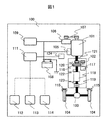
- FIG. 1 is a diagram illustrating a configuration of a vehicle 100 including a vehicle control device (controller) 111 according to a first embodiment.
- 3 is a flowchart for explaining processing in which a controller 111 controls the operation of an engine 101. It is a figure which shows the detail of step S202. It is a figure which illustrates an engine efficiency curve (solid line) and an equal output curve (broken line). It is an example of the control map 501 used when the controller 111 calculates
- 3 is a time chart illustrating a change with time of each parameter in the first embodiment.
- FIG. 10 is a diagram illustrating a procedure for calculating a target driving force in a constant speed running state by a controller 111 in a third embodiment.
- 10 is a flowchart illustrating processing in which a controller 111 controls the operation of an engine 101 in a vehicle 100 according to a fourth embodiment. It is a figure which shows the process image in step S1304.
- FIG. 1 is a diagram illustrating a configuration of a vehicle 100 including a vehicle control device (controller) 111 according to the first embodiment of the present invention.
- An engine 101 is mounted on the vehicle 100.
- the driving force generated by the engine 101 is transmitted to the wheels 104 connected through the differential mechanism 103 via the transmission 102, thereby causing the vehicle 100 to travel.
- the wheel 104 is provided with a brake mechanism 115.
- the braking force changes depending on the amount of pressing of the brake pad in the brake mechanism 115, and the speed of the vehicle 100 is adjusted.
- the transmission 102 includes a torque converter 116, a transmission oil pump 117, a transmission mechanism 118, and a clutch mechanism 119.
- Clutch mechanism 119 can transmit and block power from engine 101 to wheel 104.
- the transmission oil pump 117 is driven via an oil pump drive chain 120.
- the transmission mechanism 118 is not limited to a stepped transmission, and may be a continuously variable transmission in which a belt or a chain and a pulley are combined.
- the clutch mechanism 119 is not limited between the speed change mechanism 118 and the differential mechanism 103, and may be provided between the oil pump drive chain 120 and the speed change mechanism 118.
- the transmission 102 includes a transmission input rotational speed sensor 122 that measures the rotational speed of the input shaft, and a transmission output rotational speed sensor 123 that measures the rotational speed of the output shaft.
- a transmission input rotational speed sensor 122 that measures the rotational speed of the input shaft
- a transmission output rotational speed sensor 123 that measures the rotational speed of the output shaft.
- the engine 101 is assembled with a starter motor 105 as a starting device.
- the starter motor 105 is driven by supplying electric power from the battery 108, and the engine 101 also rotates in conjunction with the rotation of the starter motor 105.
- the engine starter is not limited to the starter motor 105, and a motor having functions of a starter motor and a generator may be used.
- the engine 101 is provided with an engine speed sensor 121 that detects the speed.
- the starter motor 105 is driven, and the engine 101 is started by starting fuel supply and igniting when the engine speed reaches a predetermined value or more.
- a generator 106 is connected to the engine 101 via a drive belt 107.
- the generator 106 can generate electric power by rotating following the rotation of the crankshaft.
- the generator 106 has a mechanism for changing the generated voltage by controlling the field current, and can also stop the generated output.
- the electric power generated by the generator 106 is supplied to the battery 108, the in-vehicle electrical component 109, and the controller 111.
- the in-vehicle electrical component 109 includes an actuator (for example, a fuel supply device and an ignition device) for operating the engine 101, a lighting device such as a headlight, a brake lamp, and a direction indicator, an air conditioner such as a blower fan and a heater. .
- the controller 111 controls the in-vehicle electrical component 109 including these.
- an accelerator pedal depression amount sensor 112 that detects the depression amount of the accelerator pedal
- a brake pedal depression amount sensor 113 that detects the depression amount of the brake pedal
- a vehicle speed sensor 114 that detects the vehicle speed. The information detected by is input.
- the brake mechanism 115 can change the pressing amount according to the command value from the controller 111 as well as the mechanism for controlling the braking force by changing the pressing amount of the brake pad according to the depression amount of the brake pedal of the driver. It may be provided with a simple electric actuator mechanism.
- FIG. 2 is a flowchart for explaining processing in which the controller 111 controls the operation of the engine 101.
- the controller 111 controls the operation of the engine 101 by, for example, periodically executing this flowchart.
- each step of FIG. 2 will be described.
- Step S201 The controller 111 determines whether the clutch mechanism 119 is open or engaged. Specifically, (a) the engagement pressure of the clutch mechanism 119 is measured using a hydraulic pressure sensor, and (b) the clutch when there is a difference in the rotational speed between the transmission output rotational speed sensor 123 and the vehicle speed. The state of the clutch mechanism 119 is determined using a technique such as determining that the clutch mechanism is in the released state. When it is determined that the clutch mechanism 119 is in the released state, the process proceeds to S202, and when it is determined that the clutch mechanism 119 is in the engaged state, this flowchart is ended.
- Step S202 The controller 111 calculates the target driving force F t according to the vehicle speed detected by the vehicle speed sensor 114 and the accelerator opening detected by the accelerator pedal depression amount sensor 112. Details of this step will be described again with reference to FIG.
- the controller 111 calculates the target engine output P t_e according to the following equation (1).
- F t is the target driving force
- M is the vehicle weight
- C d is the air resistance coefficient
- S is the front projected area of the vehicle
- V is the vehicle speed
- ⁇ is the rolling resistance coefficient
- g is the gravitational acceleration
- ⁇ is the road surface. Represents the slope.
- Step S204 The controller 111 calculates a target engine speed based on the target engine output. Details of this step will be described with reference to FIGS.
- Step S205 The controller 111 calculates a target gear ratio based on the target engine output, the vehicle speed, the accelerator opening, and the transmission output speed. Details of this step will be described with reference to FIG.
- Step S206 The controller 111 determines whether or not the actual gear ratio has reached the target gear ratio. If the target speed ratio is different from the actual speed ratio, the process proceeds to S207. If the target speed ratio is the same as the actual speed ratio, the process proceeds to S210. This step is for driving the engine at an operating point with good engine efficiency by first controlling the gear ratio before controlling the engine speed.
- Step S207 The controller 111 determines whether or not the engine 101 is stopped based on the detection result of the engine speed sensor 121. Specifically, by shifting from the state where the fuel supply to the engine 101 is cut to the state where the fuel is supplied again, the minimum engine speed (400 to 500 r / min) at which engine idling can be resumed is reached. If it is, it is determined that the engine 101 is operating. Otherwise, it is determined that the engine 101 is stopped. If the engine 101 is stopped, the process proceeds to step S208; otherwise, the process skips to step S209.
- Step S208 The controller 111 cranks the engine speed until the engine speed reaches a predetermined speed by the engine starting device, and performs fuel supply and ignition after a predetermined condition is satisfied. As a result, the engine 101 is returned to the idling speed or higher.
- the controller 111 controls the transmission mechanism 118 so as to achieve the target transmission ratio by supplying a predetermined hydraulic pressure to the transmission mechanism 118.
- Step S210 The controller 111 controls the throttle, ignition timing, and the like so as to increase the engine speed to the transmission input speed after the actual speed ratio reaches the target speed ratio.
- Step S208 and S210 Supplement
- the timing for controlling the engine speed may be delayed, leading to an acceleration delay. Therefore, for example, it may be detected by appropriate means that the time required for the actual gear ratio to reach the target gear ratio is within a predetermined value, and the process may proceed from step S208 to S210 at that timing.
- Step S211 The controller 111 determines whether or not the engine speed and the transmission input speed are synchronized (that is, the difference between the engine speed and the transmission input speed has become a predetermined value or less). If synchronized, the process proceeds to step S212, and if not synchronized, this flowchart ends.
- Step S211 The controller 111 smoothly engages the clutch by gradually supplying a predetermined hydraulic pressure to the clutch mechanism 119.
- FIG. 3 is a diagram showing details of step S202.
- the controller 111 performs control calculation so that the target driving force increases as the accelerator opening degree increases.
- the relationship of accelerator opening / vehicle speed / target driving force is as exemplified in FIG.
- the relationship between these parameters exemplified in FIG. 3 can be stored in advance in a suitable storage device as a parameter such as a control map.
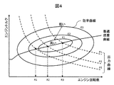
- FIG. 4 is a diagram illustrating an engine efficiency curve (solid line) and an iso-output curve (dashed line).
- the horizontal axis in FIG. 4 represents the engine speed, and the vertical axis represents the engine torque.
- the engine efficiency curve E1, E2, E3
- the engine efficiency is highest at the center of the ellipse, and the efficiency decreases as the distance from the center increases.
- an optimum fuel consumption curve is represented by connecting the points with the highest efficiency among the engine equal output curves (P1, P2, P3).
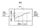
- FIG. 5 is an example of the control map 501 used when the controller 111 obtains the target engine speed based on the target engine output. Since the engine efficiency characteristics differ depending on the type of engine, the relationship between the target engine output and the optimal target engine speed corresponding to this (the relationship shown in FIG. 4) was derived and described.
- the control map 501 can be stored in an appropriate storage device in advance.
- the controller 111 can calculate the target engine speed using the control map 501.
- FIG. 6 is a diagram for explaining the processing procedure in step S205.
- the controller 111 calculates the target transmission input rotational speed based on the vehicle speed and the accelerator opening.
- the relationship between the target transmission input rotational speed / vehicle speed / accelerator opening can be calculated in advance and stored in an appropriate storage device as the target transmission input rotational speed map 601, for example.
- the target transmission input rotational speed map 601 is set so that the target transmission input rotational speed increases as the accelerator opening increases.
- the controller 111 can calculate the target transmission input rotational speed using the target transmission input rotational speed map 601.
- the controller 111 inputs the larger one of the target engine speed calculated in step S204 and the target transmission input speed calculated based on the target transmission input speed map 601 to the transmission 102. Used as the final target transmission input rotational speed. As a result, when the target output is large, a small gear ratio is not selected, so that fuel efficiency can be improved while ensuring acceleration performance.
- the controller 111 calculates the target gear ratio by dividing the target transmission input rotational speed to be finally used by the transmission output rotational speed detected by the transmission output rotational speed sensor 123.
- FIG. 7 is a time chart illustrating the change with time of each parameter in the first embodiment.
- the time-dependent change of each parameter by the conventional control is indicated by a dotted line
- the time-dependent change of each parameter by the control of the first embodiment is indicated by a solid line.
- the controller 111 When the controller 111 detects that the accelerator is turned off, the controller 111 releases the clutch.
- the engine speed gradually decreases to 0, and the gear ratio also changes from low to high.
- the operation after the accelerator is turned on differs between the conventional control and the control in the first embodiment.
- the gear ratio is maintained until the clutch is engaged after the accelerator is turned on.
- the gear ratio is controlled until the target rotational speed is reached after the clutch is engaged. Therefore, since the engine is driven at a rotational speed with low engine efficiency, fuel efficiency is deteriorated.
- the transmission gear ratio is shifted to low (see S206 to S209), and after shifting until the transmission input rotational speed reaches the target rotational speed, the clutch is engaged ( (See S210 to S212).
- the engine 101 is driven at a high engine speed so that fuel efficiency can be improved.
- the controller 111 controls the speed ratio to the target speed ratio before increasing the engine speed, and then controls the engine speed and then engages the clutch. As a result, the engine 101 can be driven at a high engine speed and fuel efficiency can be improved.
- Embodiment 2 of the present invention an example will be described in which the control method described in Embodiment 1 is applied to automatic acceleration / deceleration control that repeats sailing stop and acceleration within a preset vehicle speed range. Since the vehicle 100 and its components are the same as those in the first embodiment, the differences will be mainly described below.
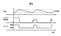
- FIG. 8 is a time chart illustrating automatic acceleration / deceleration control that repeats sailing stop and acceleration within a specified vehicle speed range.
- the controller 111 accelerates the vehicle 100 until the vehicle speed reaches the set upper limit vehicle speed.
- the clutch is released, the engine 101 is stopped, and the sailing stop is performed. Thereafter, when the vehicle 100 reaches the lower limit vehicle speed, the engine 101 is restarted, the clutch is engaged, and then the vehicle 100 is accelerated. Thereafter, the same control procedure is repeated.
- FIG. 9 is a flowchart for explaining processing in which the controller 111 controls the operation of the engine 101 in the second embodiment.
- FIG. 8 a flowchart in which the control procedure of the first embodiment is applied to automatic acceleration / deceleration control that repeats sailing stop and acceleration within a specified vehicle speed range will be described. Description of the same steps as those in FIG. 2 is omitted, and additional and changed steps will be described.
- Step S901 The controller 111 performs this step after step S201.
- the controller 111 at the time of running in the clutch released state, then the estimated time T a to reacceleration start the vehicle 100.
- the vehicle acceleration ⁇ s in the clutch released state is calculated according to the following formula (2).
- the estimated time T a to re-acceleration during travel clutch open state can be calculated by the following equation (3).
- V 0 represents the current vehicle speed
- V represents the vehicle speed at which acceleration starts.
- Step S902 Controller 111, the time T a to reacceleration proceeds to step S903 if it is within a predetermined value, to continue the sailing stop by the flowchart ends and otherwise.
- Predetermined value to be compared with T a for example an engine starting time Te and the value obtained by adding the transmission delay time Tt of the transmission 102.
- the larger one of Te and Tt may be set as the predetermined value.
- the engine start time Te is, for example, the time from cranking the engine until the engine speed reaches a value greater than the idling speed.
- the controller 111 performs the following processing in addition to the processing described in step S202.
- the controller 111 calculates a vehicle speed difference between the upper limit vehicle speed and the actual vehicle speed, and sets the target acceleration ⁇ t to be larger as the vehicle speed difference is larger.
- the maximum value of the target acceleration ⁇ t is a value regulated by laws and regulations.
- Controller 111, the target driving force F a at the time of acceleration of the automatic deceleration control, is calculated according to the following equation (4).
- ⁇ t represents the target acceleration during automatic acceleration / deceleration
- M represents the vehicle weight.
- the controller 111 compares the target drive force F t, which is calculated according to the target driving force F a and step S202 calculated is employed the larger the target driving force.
- step S203 and subsequent steps the target driving force finally adopted is used.
- FIG. 10 is a time chart illustrating the change with time of each parameter in the second embodiment.
- the change with time of each parameter by the conventional control is indicated by a dotted line
- the change with time of each parameter by the control of the second embodiment is indicated by a solid line.
- the gear ratio is controlled while the engine is stopped, and the clutch is engaged after the engine 101 is started. Accelerate control. Therefore, compared with the conventional control, the engine 101 is accelerated at an operating point with high engine efficiency, so that fuel efficiency can be improved.
- FIG. 11 is a diagram illustrating a configuration of the vehicle 100 including the controller 111 according to the third embodiment of the present invention.
- the vehicle 100 includes a front situation recognition sensor 1101 in addition to the configuration described in the first embodiment.
- the forward situation recognition sensor 1101 includes at least one means for detecting the forward situation of the vehicle 100, such as a navigation system, a camera, a radar, an inter-vehicle communication, or a road-vehicle communication module.
- the controller 111 can acquire the inter-vehicle distance and the relative speed (preceding vehicle speed ⁇ own vehicle speed) between the vehicle 100 and the preceding vehicle based on the detection result of the forward situation recognition sensor 1101.
- FIG. 12 is a diagram illustrating a procedure by which the controller 111 calculates the target driving force in the constant speed traveling state in the third embodiment.
- the controller 111 calculates the target acceleration ⁇ f using the inter-vehicle distance from the preceding vehicle and the relative speed as input parameters.
- the controller 111 further calculates a target acceleration based on the difference between the set vehicle speed and the actual vehicle speed in the constant speed running state as input parameters.
- the controller 111 compares the two calculated target accelerations, and adopts the smaller one as the target acceleration ⁇ t .
- the controller 111 obtains a target driving force F a by multiplying the target acceleration ⁇ t by the vehicle weight M.
- constant speed running control can be executed when no preceding vehicle is detected, and automatic acceleration / deceleration control can be executed so as not to collide when a preceding vehicle is detected.
- the correspondence relationship between each input parameter and the target acceleration can be stored in advance in an appropriate storage device in the form of a control map, for example.
- the control map is set in advance so that the target acceleration ⁇ f increases as the inter-vehicle distance increases and increases as the relative speed increases (that is, the preceding vehicle speed is higher than the host vehicle speed).
- FIG. 13 is a flowchart illustrating a process in which the controller 111 controls the operation of the engine 101 in the vehicle 100 according to the fourth embodiment of the present invention.
- the vehicle 100 has the same configuration as that of the third embodiment. Since the other configuration is the same as that of the third embodiment, the difference will be mainly described below.
- Step S1301 The controller 111 executes this step and the following step S1302 instead of step S901.
- the controller 111 assumes that the preceding person makes a uniform acceleration motion based on information (position X p (t), speed V p (t)) of the preceding vehicle at the time t, and the time t + t n (0 ⁇ t
- the predicted values of the position and speed of the preceding vehicle in ( n ⁇ t max ) are calculated according to the following formulas (5) and (6).
- the controller 111 calculates predicted values of the position and speed of the vehicle at time t + 1 according to the following formulas (7) and (8).
- the time t + 1 and later can also be calculated sequentially.
- Controller 111 the position of the preceding vehicle X p (t), preceding vehicle velocity V p (t), based on the position of the vehicle X (t), the speed of the vehicle V (t), the following equation (9) ( 10), a predicted value D (t) of the inter-vehicle distance and a predicted value V r (t) of the relative speed at time t are calculated. The same calculation can be made for time t and thereafter.
- the controller 111 calculates the target acceleration predicted value ⁇ f (t) of the own vehicle according to the procedure described in FIG. 12 based on the predicted value D (t) of the inter-vehicle distance and the predicted value V r (t) of the relative speed. To do.
- the target acceleration predicted values ⁇ f (t + 1) to ⁇ f (t + t n ) from time t + 1 to time t + t n can be calculated in the same manner.
- the controller 111 predicts the target driving force predicted value F a (t) ,. Calculate (t + t n ).
- Controller 111 from the current time t, the target driving force estimated value F a (t), ⁇ , the time until one of the F a (t + t n) is greater than 0, as T a at step S901 adopt.
- Step S1303 The controller 111 executes this step and the following step S1304 instead of steps S902 to S204 in FIG.
- the controller 111 calculates the target engine output predicted value P e (t + t n ) at time t + t n according to the following equation (11).
- Step S1304 The controller 111 calculates the target engine speed based on the average value of the target engine output predicted value. The processing image of this step will be described with reference to FIG.
- FIG. 14 is a diagram showing a processing image in step S1304.
- the controller 111 calculates an average value P e_ave of the target engine output predicted values P e (t) to P e (t + t n ) from time t to time t + t n .
- the controller 111 calculates the target engine speed by applying the average value Pe_ave of the target engine output predicted value to the control map 501 described in FIG. Thereby, the fluctuation
- the present invention is not limited to the above embodiment, and includes various modifications.
- the above-described embodiment has been described in detail for easy understanding of the present invention, and is not necessarily limited to one having all the configurations described.
- a part of the configuration of an embodiment can be replaced with the configuration of another embodiment, and the configuration of another embodiment can be added to the configuration of an embodiment.
- control map as the means for calculating each parameter has been described.
- other means may be used as long as the relationship between parameters is defined.
- a function that defines an equivalent relationship can be used.
- the above components, functions, processing units, processing means, etc. may be realized in hardware by designing some or all of them, for example, with an integrated circuit.
- Each of the above-described configurations, functions, and the like may be realized by software by interpreting and executing a program that realizes each function by the processor.
- Information such as programs, tables, and files for realizing each function can be stored in a recording device such as a memory, a hard disk, an SSD (Solid State Drive), or a recording medium such as an IC card, an SD card, or a DVD.
- each control process performed by the controller 111 stores a control program in a storage device such as a memory provided in the controller 111 in advance, and an arithmetic device such as a CPU (Central Processing Unit) provided in the controller 111 executes the control program. This can be realized.
- a storage device such as a memory provided in the controller 111 in advance
- an arithmetic device such as a CPU (Central Processing Unit) provided in the controller 111 executes the control program. This can be realized.
- CPU Central Processing Unit
- SYMBOLS 100 Vehicle 101: Engine 102: Transmission 103: Differential mechanism 104: Wheel 105: Starter motor 106: Generator 107: Drive belt 108: Battery 109: On-vehicle electrical equipment 111: Controller 112: Accelerator pedal depression amount sensor 113: Brake Pedal depression amount sensor 114: vehicle speed sensor 115: brake mechanism 116: torque converter 117: transmission oil pump 118: transmission mechanism 119: clutch mechanism 120: oil pump drive chain 121: engine speed sensor 122: transmission input speed Sensor 123: Transmission output speed sensor 124: Electric oil pump 1101: Front situation recognition sensor
Landscapes
- Engineering & Computer Science (AREA)
- Mechanical Engineering (AREA)
- Chemical & Material Sciences (AREA)
- Combustion & Propulsion (AREA)
- Transportation (AREA)
- General Engineering & Computer Science (AREA)
- Automation & Control Theory (AREA)
- Physics & Mathematics (AREA)
- Fluid Mechanics (AREA)
- Control Of Driving Devices And Active Controlling Of Vehicle (AREA)
- Control Of Vehicle Engines Or Engines For Specific Uses (AREA)
- Hydraulic Clutches, Magnetic Clutches, Fluid Clutches, And Fluid Joints (AREA)
- Control Of Transmission Device (AREA)
Abstract
エンジン効率の高い動作点でエンジンを駆動させ、燃費を向上させる。 本発明に係る車両制御装置は、エンジンの回転数を増加させる前に変速比を制御し、その後にクラッチを締結する。
Description
本発明は、車両制御装置に関する。
近年、内燃機関を備えたエンジンの燃費を向上させるための様々な技術が開発されている。下記特許文献1は、『走行中の車両において惰行による走行時間や走行距離を長く確保できる車両の制御装置を提供すること。』を課題として、『車両の制御装置は、車両の車速Vが下限側車速V0および上限側車速V1で決定される車速域内にあるとき、車速Vが車速V0以上であればフューエルカットによりエンジンを停止させてクラッチを開放して惰行により車両を走行させ、車速Vが車速V0を下回ると燃料供給によりエンジンを始動させてクラッチを係合して加速させる(定速フリーラン)。車両を停止させる必要があるときは、車両が停止するまでフューエルカットによりエンジンを停止させてクラッチを開放して惰行により車両を走行させた後(停止フリーラン)、クラッチを係合してエンジンブレーキおよびブレーキ装置による制動を付与する。これにより、惰行による走行時間や走行距離を長く確保できて燃費を向上させることができる。』という技術を開示している(要約参照)。
クラッチを係合状態にし、エンジンに対する燃料供給を停止させて車両を走行(以下、エンジンブレーキ)させた場合、エンジンブレーキの減速度は、走行抵抗に、エンジンの損失(機械損失や吸気損失など)を加算したものとなる。一方、エンジンを停止し、かつクラッチを開放した状態で車両を走行(特許文献1における停止フリーラン、以下ではセーリングストップとも呼ぶ)させた場合、セーリングストップの減速度は走行抵抗のみとなるので、エンジンブレーキの減速度よりも小さくなる。
したがって特許文献1においては、車両を停止させる必要があると判断し、停止までの距離が所定値以上の場合には、まずセーリングストップを実施した上で、停止までの距離が所定値未満になるとエンジンブレーキあるいはブレーキにて減速させる(段落0066など参照)。特許文献1においては、上記動作によりエンジン停止時間を長くして燃費を向上させることを図っている。
上記特許文献1においては、車速が下限車速以下になるとエンジンを始動し、クラッチを締結状態にして加速させるときに変速比を制御する。これにより、エンジンの最良燃費領域で駆動するように変速比を制御することを図っている。しかしながら、変速機を所定の変速比に制御する際にある程度の遅れが生じる。そのため、エンジン始動後、クラッチを締結し、エンジン効率の高い動作点に到達するまでには、エンジン効率の低い動作点で駆動する必要があり、これにともなって燃費効果が小さくなる。
本発明は、上記課題を解決するためになされたものであり、エンジン効率の高い動作点でエンジンを駆動させ、燃費を向上することを目的とする。
本発明に係る車両制御装置は、エンジンの回転数を増加させる前に変速比を制御し、その後にクラッチを締結する。
本発明に係る車両制御装置によれば、エンジン効率のよい動作点に到達するまでの時間を短縮することにより、燃費を向上させることができる。
<実施の形態1>
図1は、本発明の実施形態1に係る車両制御装置(コントローラ)111を備えた車両100の構成を示す図である。車両100にはエンジン101が搭載されている。エンジン101が発生させた駆動力は、変速機102を経て、ディファレンシャル機構103を介して連結された車輪104に伝達され、これにより車両100を走行させる。車両100を減速させるため、車輪104にはブレーキ機構115が備えられている。ブレーキ機構115内のブレーキパッドの押し当て量によって制動力が変化し、車両100の速度を調整する。
図1は、本発明の実施形態1に係る車両制御装置(コントローラ)111を備えた車両100の構成を示す図である。車両100にはエンジン101が搭載されている。エンジン101が発生させた駆動力は、変速機102を経て、ディファレンシャル機構103を介して連結された車輪104に伝達され、これにより車両100を走行させる。車両100を減速させるため、車輪104にはブレーキ機構115が備えられている。ブレーキ機構115内のブレーキパッドの押し当て量によって制動力が変化し、車両100の速度を調整する。
変速機102は、トルクコンバータ116、変速機オイルポンプ117、変速機構118、クラッチ機構119を備える。クラッチ機構119は、エンジン101からの動力を車輪104に伝達および遮断することができる。変速機オイルポンプ117は、オイルポンプ駆動用チェーン120を介して駆動される。変速機構118は、有段変速機に限定されず、ベルトあるいはチェーンとプーリを組み合わせた無段変速機でもよい。クラッチ機構119は、変速機構118とディファレンシャル機構103の間に限定されず、オイルポンプ駆動用チェーン120と変速機構118との間に設けてもよい。変速機102は、入力軸の回転数を計測する変速機入力回転数センサ122、出力軸の回転数を計測する変速機出力回転数センサ123、を備えている。セーリングストップ中などエンジン101が停止すると、変速機オイルポンプ117が駆動できないため、変速比を維持する油圧が不足する。そこで、エンジン101停止中の変速機102の油圧を確保するため、変速機用の電動オイルポンプ124が備えられている。バッテリ108から電動オイルポンプ124に対して電力を供給することにより、必要な油圧を確保する。
エンジン101には、始動装置としてスタータモータ105が組みつけられている。バッテリ108から電力を供給することによりスタータモータ105を駆動し、スタータモータ105の回転に連動してエンジン101も回転する。エンジン始動装置としてはスタータモータ105に限定されず、スタータモータと発電機の機能を有したモータを用いてもよい。エンジン101には、回転数を検出するエンジン回転数センサ121が取り付けられている。スタータモータ105を駆動させ、エンジン回転数が所定値以上になったときに燃料供給を開始し点火させることにより、エンジン101を始動する。
エンジン101には、駆動ベルト107を介して発電機106が連結される。発電機106は、クランク軸の回転に従動して回転することにより電力を発生させることができる。発電機106は、界磁電流を制御することにより発電電圧を可変にする機構を有しており、発電出力を停止することもできる。発電機106が発電した電力は、バッテリ108と車載電装品109およびコントローラ111に対して供給される。車載電装品109は、エンジン101を動作させるためのアクチュエータ(例えば、燃料供給装置、点火装置)、ヘッドライト、ブレーキランプ、方向指示器などの灯火装置、ブロアファン、ヒータなどの空調機器などを含む。コントローラ111は、これらを含む車載電装品109を制御する。
コントローラ111には、アクセルペダルの踏み込み量を検出するアクセルペダル踏み込み量センサ112、ブレーキペダルの踏み込み量を検出するブレーキペダル踏み込み量センサ113、車両の速度を検出する車速センサ114、が接続され、これらが検出した情報が入力される。
ブレーキ機構115は、運転手のブレーキペダル踏み込み量に応じてブレーキパッドの押し当て量が変化し制動力を制御する機構だけでなく、コントローラ111からの指令値によって押し当て量を変化させることが可能な電動アクチュータ機構を備えたものでもよい。
図2は、コントローラ111がエンジン101の動作を制御する処理を説明するフローチャートである。コントローラ111は、本フローチャートを例えば周期的に実行することにより、エンジン101の動作を制御する。以下図2の各ステップについて説明する。
(図2:ステップS201)
コントローラ111は、クラッチ機構119が開放されているかそれとも締結されているかを判定する。具体的には、(a)油圧センサを用いてクラッチ機構119の締結圧を測定する、(b)変速機出力回転数センサ123と車速との間の回転数の差が生じている場合はクラッチが開放状態と判定する、などの手法を用いてクラッチ機構119の状態を判定する。クラッチ機構119が開放状態と判定されたときはS202に進み、クラッチ機構119が締結状態と判定されたときは本フローチャートを終了する。
コントローラ111は、クラッチ機構119が開放されているかそれとも締結されているかを判定する。具体的には、(a)油圧センサを用いてクラッチ機構119の締結圧を測定する、(b)変速機出力回転数センサ123と車速との間の回転数の差が生じている場合はクラッチが開放状態と判定する、などの手法を用いてクラッチ機構119の状態を判定する。クラッチ機構119が開放状態と判定されたときはS202に進み、クラッチ機構119が締結状態と判定されたときは本フローチャートを終了する。
(図2:ステップS202)
コントローラ111は、車速センサ114が検出する車速と、アクセルペダル踏み込み量センサ112が検出するアクセル開度とに応じて、目標駆動力Ftを算出する。本ステップの詳細については後述の図3を用いて改めて説明する。
コントローラ111は、車速センサ114が検出する車速と、アクセルペダル踏み込み量センサ112が検出するアクセル開度とに応じて、目標駆動力Ftを算出する。本ステップの詳細については後述の図3を用いて改めて説明する。
(図2:ステップS203)
コントローラ111は、目標エンジン出力Pt_eを下記式(1)にしたがって算出する。同式において、Ftは目標駆動力、Mは車両重量、Cdは空気抵抗係数、Sは車両の前面投影面積、Vは車両速度、μは転がり抵抗係数、gは重力加速度、θは路面勾配を表している。
コントローラ111は、目標エンジン出力Pt_eを下記式(1)にしたがって算出する。同式において、Ftは目標駆動力、Mは車両重量、Cdは空気抵抗係数、Sは車両の前面投影面積、Vは車両速度、μは転がり抵抗係数、gは重力加速度、θは路面勾配を表している。

(図2:ステップS204)
コントローラ111は、目標エンジン出力に基づき目標エンジン回転数を演算する。本ステップの詳細については後述の図4~図5を用いて説明する。
コントローラ111は、目標エンジン出力に基づき目標エンジン回転数を演算する。本ステップの詳細については後述の図4~図5を用いて説明する。
(図2:ステップS205)
コントローラ111は、目標エンジン出力、車速、アクセル開度、変速機出力回転数に基づき、目標変速比を算出する。本ステップの詳細については後述の図6を用いて説明する。
コントローラ111は、目標エンジン出力、車速、アクセル開度、変速機出力回転数に基づき、目標変速比を算出する。本ステップの詳細については後述の図6を用いて説明する。
(図2:ステップS206)
コントローラ111は、実際の変速比が目標変速比に到達したか否かを判定する。目標変速比が実際の変速比と異なる場合はS207へ進み、目標変速比が実際の変速比と同じに至っている場合はS210へ進む。本ステップは、エンジン回転数を制御する前にまず変速比を制御することにより、エンジン効率のよい動作点においてエンジンを駆動するためのものである。
コントローラ111は、実際の変速比が目標変速比に到達したか否かを判定する。目標変速比が実際の変速比と異なる場合はS207へ進み、目標変速比が実際の変速比と同じに至っている場合はS210へ進む。本ステップは、エンジン回転数を制御する前にまず変速比を制御することにより、エンジン効率のよい動作点においてエンジンを駆動するためのものである。
(図2:ステップS207)
コントローラ111は、エンジン回転数センサ121の検出結果に基づき、エンジン101が停止状態であるか否かを判定する。具体的には、エンジン101に対する燃料供給がカットされている状態から再び燃料を供給する状態に移行することにより、エンジンアイドリングを再開することができる最小エンジン回転数(400~500r/min)に至っている場合、エンジン101が稼働していると判定する。それ以外はエンジン101が停止していると判定する。エンジン101が停止している場合はステップS208へ進み、それ以外であればステップS209へスキップする。
コントローラ111は、エンジン回転数センサ121の検出結果に基づき、エンジン101が停止状態であるか否かを判定する。具体的には、エンジン101に対する燃料供給がカットされている状態から再び燃料を供給する状態に移行することにより、エンジンアイドリングを再開することができる最小エンジン回転数(400~500r/min)に至っている場合、エンジン101が稼働していると判定する。それ以外はエンジン101が停止していると判定する。エンジン101が停止している場合はステップS208へ進み、それ以外であればステップS209へスキップする。
(図2:ステップS208)
コントローラ111は、エンジン始動装置によってエンジン回転数が所定回転数になるまでクランキングし、所定条件が成立した後に燃料供給および点火を実施する。これにより、エンジン101を上述のアイドリング回転数以上に復帰させる。
コントローラ111は、エンジン始動装置によってエンジン回転数が所定回転数になるまでクランキングし、所定条件が成立した後に燃料供給および点火を実施する。これにより、エンジン101を上述のアイドリング回転数以上に復帰させる。
(図2:ステップS209)
コントローラ111は、変速機構118に対して所定の油圧を供給することにより、目標変速比となるように変速機構118を制御する。
コントローラ111は、変速機構118に対して所定の油圧を供給することにより、目標変速比となるように変速機構118を制御する。
(図2:ステップS210)
コントローラ111は、実際の変速比が目標変速比に到達した後、エンジン回転数を変速機入力回転数まで上昇させるように、スロットルや点火時期などを制御する。
コントローラ111は、実際の変速比が目標変速比に到達した後、エンジン回転数を変速機入力回転数まで上昇させるように、スロットルや点火時期などを制御する。
(図2:ステップS208およびS210:補足)
ステップS208において、実際の変速比が目標変速比に到達してからステップS210へ進むと、エンジン回転数を制御するタイミングが遅れて加速遅れにつながる可能性がある。そこで例えば、実際の変速比が目標変速比に到達する時間が所定値以内になったことを適当な手段により検出し、そのタイミングでステップS208からS210へ進んでもよい。
ステップS208において、実際の変速比が目標変速比に到達してからステップS210へ進むと、エンジン回転数を制御するタイミングが遅れて加速遅れにつながる可能性がある。そこで例えば、実際の変速比が目標変速比に到達する時間が所定値以内になったことを適当な手段により検出し、そのタイミングでステップS208からS210へ進んでもよい。
(図2:ステップS211)
コントローラ111は、エンジン回転数と変速機入力回転数が同期(すなわち、エンジン回転数と変速機入力回転数との間の差が所定値以下になった)したか否かを判定する。同期した場合はステップS212へ進み、同期していない場合は本フローチャートを終了する。
コントローラ111は、エンジン回転数と変速機入力回転数が同期(すなわち、エンジン回転数と変速機入力回転数との間の差が所定値以下になった)したか否かを判定する。同期した場合はステップS212へ進み、同期していない場合は本フローチャートを終了する。
(図2:ステップS211)
コントローラ111は、クラッチ機構119に対して所定の油圧を徐々に供給することにより、クラッチを滑らかに締結する。
コントローラ111は、クラッチ機構119に対して所定の油圧を徐々に供給することにより、クラッチを滑らかに締結する。
図3は、ステップS202の詳細を示す図である。コントローラ111は、アクセル開度が大きいほど目標駆動力が大きくなるように、制御演算を実施する。アクセル開度/車速/目標駆動力の関係は、例えば図3に例示するようなものとなる。図3に例示するこれらパラメータ間の関係は、例えばあらかじめ制御マップなどのパラメータとして適当な記憶装置に格納しておくことができる。
図4は、エンジンの効率曲線(実線)と等出力曲線(破線)を例示する図である。図4の横軸はエンジン回転数、縦軸はエンジントルクを表す。エンジン効率は一般的に、エンジン効率曲線(E1,E2,E3)が示すように、楕円の中心が最も効率が高く、中心から離れるほど効率が低くなる。図4において、エンジンの等出力曲線(P1,P2,P3)のなかで最も効率が高い点を結んだものを最適燃費曲線と表している。
図4に示すように、ある目標エンジン出力を得つつエンジンを効率よく動作させるためには、その目標エンジン出力に対応する最適なエンジン回転数が得られるようにエンジンを制御する必要がある。例えば目標エンジン出力がP1である場合、目標エンジン回転数をR1としてエンジンを制御する必要がある。
図5は、コントローラ111が目標エンジン出力に基づき目標エンジン回転数を求める際に用いる制御マップ501の例である。エンジン効率特性はエンジンの種類に応じて異なるため、あらかじめ目標エンジン出力とこれに対応する最適な目標エンジン回転数との間の関係(図4に示すような関係)を導出し、これを記述した制御マップ501をあらかじめ適当な記憶装置に格納しておくことができる。コントローラ111は、制御マップ501を用いて目標エンジン回転数を算出することができる。
図6は、ステップS205における処理手順を説明する図である。コントローラ111は、車速とアクセル開度に基づき、目標変速機入力回転数を演算する。目標変速機入力回転数/車速/アクセル開度の関係は、例えばあらかじめ算出した上で目標変速機入力回転数マップ601として適当な記憶装置に格納しておくことができる。目標変速機入力回転数マップ601は、アクセル開度が大きいほど目標変速機入力回転数が大きくなるように設定する。コントローラ111は、目標変速機入力回転数マップ601を用いて目標変速機入力回転数を算出することができる。
コントローラ111は、ステップS204で算出した目標エンジン回転数と、目標変速機入力回転数マップ601に基づき算出した目標変速機入力回転数とのうちいずれか大きい方を、変速機102に対して入力する最終的な目標変速機入力回転数として用いる。これにより、目標出力が大きい時に小さい変速比が選ばれることがなくなるため、加速性能を担保しつつ燃費を向上することができる。
コントローラ111は、最終的に用いる目標変速機入力回転数を、変速機出力回転数センサ123が検出する変速機出力回転数によって除算することにより、目標変速比を演算する。
図7は、本実施形態1における各パラメータの経時変化を例示するタイムチャートである。図7において、従来の制御による各パラメータの経時変化を点線で示し、本実施形態1の制御による各パラメータの経時変化を実線で示す。
コントローラ111は、アクセルがOFFされたことを検出すると、クラッチを開放する。エンジン回転数は次第に減少して0となり、変速比もローからハイに遷移する。アクセルがONされた後の動作は、従来制御と本実施形態1における制御との間で異なる。
従来制御においては、アクセルがONされた後、クラッチが締結されるまで、変速比は維持される。クラッチが締結された後に目標回転数になるまで変速比を制御する。したがって、エンジン効率の低い回転数においてエンジンを駆動することになるので、燃費が悪化する。
本実施形態1の制御においては、アクセルがONされると、変速比をローにシフトし(S206~S209参照)、変速機入力回転数が目標回転数になるまで変速した後にクラッチを締結する(S210~S212参照)。これにより、エンジン効率の高い回転数においてエンジン101を駆動することになるので、燃費を向上することができる。
<実施の形態1:まとめ>
本実施形態1に係るコントローラ111は、エンジン回転数を上げる前に変速比を目標変速比まで制御し、その後にエンジン回転数を制御した上でクラッチを締結する。これにより、エンジン効率の高い回転数においてエンジン101を駆動させ、燃費を向上させることができる。
本実施形態1に係るコントローラ111は、エンジン回転数を上げる前に変速比を目標変速比まで制御し、その後にエンジン回転数を制御した上でクラッチを締結する。これにより、エンジン効率の高い回転数においてエンジン101を駆動させ、燃費を向上させることができる。
<実施の形態2>
本発明の実施形態2では、あらかじめ設定された車速幅内においてセーリングストップと加速を繰り返す自動加減速制御に対して実施形態1で説明した制御手法を適用する例について説明する。車両100とその構成要素については実施形態1と同様であるため、以下では主に差異点について説明する。
本発明の実施形態2では、あらかじめ設定された車速幅内においてセーリングストップと加速を繰り返す自動加減速制御に対して実施形態1で説明した制御手法を適用する例について説明する。車両100とその構成要素については実施形態1と同様であるため、以下では主に差異点について説明する。
図8は、規定車速幅内においてセーリングストップと加速を繰り返す自動加減速制御について説明するタイムチャートである。コントローラ111は、車速が設定された上限車速に至るまで車両100を加速する。車両100が上限車速に至ると、クラッチを開放およびエンジン101を停止し、セーリングストップを実施する。その後車両100が下限車速に至ると、エンジン101を再始動し、クラッチを締結した後、車両100を加速する。以後同様の制御手順を繰り返す。
図9は、本実施形態2においてコントローラ111がエンジン101の動作を制御する処理を説明するフローチャートである。ここでは図8で例示したように、規定車速幅内においてセーリングストップと加速を繰り返す自動加減速制御に対して実施形態1の制御手順を適用したフローチャートを説明する。図2と同じステップについては説明を省略し、追加変更したステップについて説明する。
(図9:ステップS901)
コントローラ111は、ステップS201の後に本ステップを実施する。コントローラ111は、クラッチ開放状態で走行している時点において、次に車両100を再加速開始するまでの時間Taを推定する。まず、クラッチ開放状態における車両加速度αsを下記式(2)にしたがって算出する。
コントローラ111は、ステップS201の後に本ステップを実施する。コントローラ111は、クラッチ開放状態で走行している時点において、次に車両100を再加速開始するまでの時間Taを推定する。まず、クラッチ開放状態における車両加速度αsを下記式(2)にしたがって算出する。

車両100が規定車速幅内で走行している場合、クラッチ開放状態で走行中における再加速までの推定時間Taは、下記式(3)によって算出することができる。同式において、V0は現在の車速を表し、Vは加速を開始する車速を表す。

(図9:ステップS902)
コントローラ111は、再加速までの時間Taが所定値以内であればステップS903へ進み、それ以外であれば本フローチャートを終了することによってセーリングストップを継続する。Taと比較する所定値は、例えばエンジン始動時間Teと変速機102の変速遅れ時間Ttを加算した値とする。あるいは、TeとTtのいずれか大きい方を所定値としてもよい。エンジン始動時間Teは、例えばエンジンをクランキングしてエンジン回転数がアイドリング回転数よりも大きな値に至るまでの時間とする。
コントローラ111は、再加速までの時間Taが所定値以内であればステップS903へ進み、それ以外であれば本フローチャートを終了することによってセーリングストップを継続する。Taと比較する所定値は、例えばエンジン始動時間Teと変速機102の変速遅れ時間Ttを加算した値とする。あるいは、TeとTtのいずれか大きい方を所定値としてもよい。エンジン始動時間Teは、例えばエンジンをクランキングしてエンジン回転数がアイドリング回転数よりも大きな値に至るまでの時間とする。
(図9:ステップS903)
コントローラ111は、ステップS202で説明した処理に加えて以下の処理を実施する。コントローラ111は、上限車速と実際の車速との間の車速差を算出し、この車速差が大きいほど目標加速度αtを大きく設定する。目標加速度αtの最大値は、法規等によって規制された値とする。コントローラ111は、自動加減速制御の加速時の目標駆動力Faを、下記式(4)にしたがって算出する。式(4)において、αtは自動加減速時に
目標加速度、Mは車両重量を表す。コントローラ111は、算出した目標駆動力FaとステップS202にしたがって算出した目標駆動力Ftを比較し、大きい方を目標駆動力として採用する。ステップS203以降においては、最終的に採用することとした目標駆動力を用いる。
コントローラ111は、ステップS202で説明した処理に加えて以下の処理を実施する。コントローラ111は、上限車速と実際の車速との間の車速差を算出し、この車速差が大きいほど目標加速度αtを大きく設定する。目標加速度αtの最大値は、法規等によって規制された値とする。コントローラ111は、自動加減速制御の加速時の目標駆動力Faを、下記式(4)にしたがって算出する。式(4)において、αtは自動加減速時に
目標加速度、Mは車両重量を表す。コントローラ111は、算出した目標駆動力FaとステップS202にしたがって算出した目標駆動力Ftを比較し、大きい方を目標駆動力として採用する。ステップS203以降においては、最終的に採用することとした目標駆動力を用いる。

図10は、本実施形態2における各パラメータの経時変化を例示するタイムチャートである。図10において、従来の制御による各パラメータの経時変化を点線で示し、本実施形態2の制御による各パラメータの経時変化を実線で示す。
従来制御においては、セーリングストップ状態から加速を開始する時刻t2においてエンジン101を始動し、クラッチ締結後、エンジン回転数が目標値になるように変速比を制御する。
本実施形態2の制御においては、再加速を開始するまでの時間が所定値以下になった時刻t1において、エンジン停止状態で変速比を制御し、さらにエンジン101を始動した後にクラッチを締結し、加速制御する。したがって従来制御と比較し、エンジン効率の高い動作点においてエンジン101を加速することになるので、燃費を向上することができる。
<実施の形態3>
図11は、本発明の実施形態3に係るコントローラ111を備えた車両100の構成を示す図である。本実施形態3において、車両100は実施形態1で説明した構成に加えて前方状況認識センサ1101を備える。前方状況認識センサ1101は、ナビゲーションシステム、カメラ、レーダ、車々間通信または路車間通信モジュールなど、車両100の前方状況を検出する手段を少なくとも1つ備える。コントローラ111は、前方状況認識センサ1101の検出結果に基づき、車両100と前方車両との間の車間距離や相対速度(先行車速度-自車速度)を取得することができる。
図11は、本発明の実施形態3に係るコントローラ111を備えた車両100の構成を示す図である。本実施形態3において、車両100は実施形態1で説明した構成に加えて前方状況認識センサ1101を備える。前方状況認識センサ1101は、ナビゲーションシステム、カメラ、レーダ、車々間通信または路車間通信モジュールなど、車両100の前方状況を検出する手段を少なくとも1つ備える。コントローラ111は、前方状況認識センサ1101の検出結果に基づき、車両100と前方車両との間の車間距離や相対速度(先行車速度-自車速度)を取得することができる。
図12は、本実施形態3においてコントローラ111が定速走行状態における目標駆動力を算出する手順を説明する図である。コントローラ111は、先行車との間の車間距離と相対速度を入力パラメータとして目標加速度αfを算出する。コントローラ111はさらに、定速走行状態における設定車速と実際の車速を入力パラメータとして、これらの間の差分に基づき目標加速度を算出する。
コントローラ111は、算出した2つの目標加速度を比較し、いずれか小さい方を目標加速度αtとして採用する。コントローラ111は、目標加速度αtと車両重量Mを乗算することにより目標駆動力Faを得る。これにより、先行車を検知してないときは定速走行制御を実行するとともに、先行車を検知した場合は衝突しないように自動加減速制御を実行することができる。
各入力パラメータと目標加速度との間の対応関係は、例えば制御マップなどの形式で適当な記憶装置にあらかじめ格納しておくことができる。目標加速度αfは、車間距離が大きいほど大きくなり、相対速度が大きい(すなわち、先行車速度が自車速度よりも大きい)ほど大きくなるように、あらかじめ制御マップを設定する。
<実施の形態4>
図13は、本発明の実施形態4に係る車両100においてコントローラ111がエンジン101の動作を制御する処理を説明するフローチャートである。本実施形態4において車両100は実施形態3と同様の構成を備える。その他の構成は実施形態3と同様であるため、以下では主に差異点について説明する。
図13は、本発明の実施形態4に係る車両100においてコントローラ111がエンジン101の動作を制御する処理を説明するフローチャートである。本実施形態4において車両100は実施形態3と同様の構成を備える。その他の構成は実施形態3と同様であるため、以下では主に差異点について説明する。
(図13:ステップS1301)
コントローラ111は、ステップS901に代えて本ステップと以下のステップS1302を実施する。コントローラ111は、まず時刻tにおける先行車の情報(位置Xp(t)、速度Vp(t))に基づき、当該先行者が等加速度運動をするものと想定し、時刻t+tn(0≦tn≦tmax)における先行車の位置と速度それぞれの予測値を下記式(5)(6)にしたがって算出する。
コントローラ111は、ステップS901に代えて本ステップと以下のステップS1302を実施する。コントローラ111は、まず時刻tにおける先行車の情報(位置Xp(t)、速度Vp(t))に基づき、当該先行者が等加速度運動をするものと想定し、時刻t+tn(0≦tn≦tmax)における先行車の位置と速度それぞれの予測値を下記式(5)(6)にしたがって算出する。


コントローラ111は次に、下記式(7)(8)にしたがって、時刻t+1における自車の位置と速度それぞれの予測値を算出する。時刻t+1以降についても順次算出することができる。


コントローラ111は、先行車の位置Xp(t)、先行車の速度Vp(t)、自車の位置X(t)、自車の速度V(t)に基づき、下記式(9)(10)にしたがって、時刻tにおける車間距離の予測値D(t)と相対速度の予測値Vr(t)を算出する。時刻t以降についても同様に算出することができる。


コントローラ111は、車間距離の予測値D(t)と相対速度の予測値Vr(t)に基づき、図12で説明した手順にしたがって、自車の目標加速度予測値αf(t)を算出する。時刻t+1~時刻t+tnにおける目標加速度予測値αf(t+1)~αf(t+tn)についても同様に算出することができる。コントローラ111は、目標加速度予測値αf(t),・・・,αf(t+tn)と車両重量Mの積に基づき、目標駆動力予測値Fa(t),・・・,Fa(t+tn)を算出する。
(図13:ステップS1302)
コントローラ111は、現在時刻tから、目標駆動力予測値Fa(t),・・・,Fa(t+tn)のうちいずれかが0より大きくなるまでの時間を、ステップS901におけるTaとして採用する。
コントローラ111は、現在時刻tから、目標駆動力予測値Fa(t),・・・,Fa(t+tn)のうちいずれかが0より大きくなるまでの時間を、ステップS901におけるTaとして採用する。
(図13:ステップS1303)
コントローラ111は、図9におけるステップS902~S204に代えて、本ステップと以下のステップS1304を実施する。コントローラ111は、時刻t+tnにおける目標エンジン出力予測値Pe(t+tn)を下記式(11)にしたがって算出する。
コントローラ111は、図9におけるステップS902~S204に代えて、本ステップと以下のステップS1304を実施する。コントローラ111は、時刻t+tnにおける目標エンジン出力予測値Pe(t+tn)を下記式(11)にしたがって算出する。

(図13:ステップS1304)
コントローラ111は、目標エンジン出力予測値の平均値に基づき、目標エンジン回転数を算出する。本ステップの処理イメージについては図14で説明する。
コントローラ111は、目標エンジン出力予測値の平均値に基づき、目標エンジン回転数を算出する。本ステップの処理イメージについては図14で説明する。
図14は、ステップS1304における処理イメージを示す図である。コントローラ111は、時刻t~時刻t+tnそれぞれにおける目標エンジン出力予測値Pe(t)~Pe(t+tn)の平均値Pe_aveを算出する。コントローラ111は、目標エンジン出力予測値の平均値Pe_aveを図5で説明した制御マップ501に対して適用することにより、目標エンジン回転数を算出する。これにより、エンジン回転数の上下変動などを抑制し、ドライバに対して不快感などを与えることを抑制できる。
<本発明の変形例について>
本発明は上記実施形態に限定されるものではなく、様々な変形例が含まれる。例えば、上記した実施形態は本発明を分かりやすく説明するために詳細に説明したものであり、必ずしも説明した全ての構成を備えるものに限定されるものではない。また、ある実施形態の構成の一部を他の実施形態の構成に置き換える事が可能であり、また、ある実施形態の構成に他の実施形態の構成を加えることも可能である。また、各実施形態の構成の一部について他の構成の追加・削除・置換をすることができる。
本発明は上記実施形態に限定されるものではなく、様々な変形例が含まれる。例えば、上記した実施形態は本発明を分かりやすく説明するために詳細に説明したものであり、必ずしも説明した全ての構成を備えるものに限定されるものではない。また、ある実施形態の構成の一部を他の実施形態の構成に置き換える事が可能であり、また、ある実施形態の構成に他の実施形態の構成を加えることも可能である。また、各実施形態の構成の一部について他の構成の追加・削除・置換をすることができる。
以上の実施形態において、各パラメータを算出する手段として制御マップを用いることを説明したが、パラメータ間の関係を規定するものであればその他手段を用いることもできる。例えば同等の関係を定義する関数などを用いることができる。
上記各構成、機能、処理部、処理手段等は、それらの一部や全部を、例えば集積回路で設計する等によりハードウェアで実現してもよい。また、上記の各構成、機能等は、プロセッサがそれぞれの機能を実現するプログラムを解釈し、実行することによりソフトウェアで実現してもよい。各機能を実現するプログラム、テーブル、ファイル等の情報は、メモリ、ハードディスク、SSD(Solid State Drive)等の記録装置、ICカード、SDカード、DVD等の記録媒体に格納することができる。
例えばコントローラ111が実施する各制御処理は、コントローラ111が備えるメモリなどの記憶装置に制御プログラムをあらかじめ格納しておき、コントローラ111が備えるCPU(Central Processing Unit)などの演算装置がその制御プログラムを実行することにより、実現することができる。
100:車両
101:エンジン
102:変速機
103:ディファレンシャル機構
104:車輪
105:スタータモータ
106:発電機
107:駆動ベルト
108:バッテリ
109:車載電装品
111:コントローラ
112:アクセルペダル踏み込み量センサ
113:ブレーキペダル踏み込み量センサ
114:車速センサ
115:ブレーキ機構
116:トルクコンバータ
117:変速機オイルポンプ
118:変速機構
119:クラッチ機構
120:オイルポンプ駆動用チェーン
121:エンジン回転数センサ
122:変速機入力回転数センサ
123:変速機出力回転数センサ
124:電動オイルポンプ
1101:前方状況認識センサ
101:エンジン
102:変速機
103:ディファレンシャル機構
104:車輪
105:スタータモータ
106:発電機
107:駆動ベルト
108:バッテリ
109:車載電装品
111:コントローラ
112:アクセルペダル踏み込み量センサ
113:ブレーキペダル踏み込み量センサ
114:車速センサ
115:ブレーキ機構
116:トルクコンバータ
117:変速機オイルポンプ
118:変速機構
119:クラッチ機構
120:オイルポンプ駆動用チェーン
121:エンジン回転数センサ
122:変速機入力回転数センサ
123:変速機出力回転数センサ
124:電動オイルポンプ
1101:前方状況認識センサ
Claims (7)
- 車両の動作を制御する車両制御装置であって、
前記車両と前記車両が備える車輪との間の動力伝達を断接するクラッチが切断された状態で前記車両が走行している間において、前記車両が備えるエンジンの回転数を増加させる前に前記車両が備える変速機の変速比を制御し、その後に前記クラッチを締結する
ことを特徴とする車両制御装置。 - 請求項1記載の車両制御装置において、
前記クラッチが切断された状態で前記車両が走行し、かつ、前記車両が備えるアクセルペダルの操作量が0である状態において、前記エンジンの回転数を増加させる前に前記変速比を制御し、その後に前記クラッチを締結する
ことを特徴とする車両制御装置。 - 請求項1記載の車両制御装置において、
前記クラッチが切断された状態で前記車両が走行し、かつ、前記エンジンに対する燃料噴射を中止している状態において、前記エンジンの回転数を増加させる前に前記変速比を制御し、その後に前記クラッチを締結する
ことを特徴とする車両制御装置。 - 請求項1記載の車両制御装置において、
前記クラッチを締結した後に前記エンジンの回転数を増加させる
ことを特徴とする車両制御装置。 - 請求項1記載の車両制御装置において、
前記クラッチが切断された状態から前記クラッチを締結した状態に移行した後における前記エンジンの目標回転数を演算し、
前記車両の速度および前記目標回転数に対応した変速比が得られるように前記変速機を制御する
ことを特徴とする車両制御装置。 - 請求項5記載の車両制御装置において、
前記クラッチが切断された状態から前記クラッチを締結した状態に移行した後における前記車両の目標加速度を演算し、
前記目標加速度に基づいて前記目標回転数を演算する
ことを特徴とする車両制御装置。 - 請求項1記載の車両制御装置において、
前記クラッチが切断された状態の惰性走行と、前記エンジンの回転数を増加させる駆動走行と、を繰り返すように、前記エンジンおよび前記変速機を制御する
ことを特徴とする車両制御装置。
Priority Applications (4)
| Application Number | Priority Date | Filing Date | Title |
|---|---|---|---|
| EP16850906.5A EP3357773B1 (en) | 2015-09-29 | 2016-08-05 | Vehicle control device |
| CN201680043590.3A CN108025735B (zh) | 2015-09-29 | 2016-08-05 | 车辆控制装置 |
| JP2017542992A JPWO2017056729A1 (ja) | 2015-09-29 | 2016-08-05 | 車両制御装置 |
| US15/762,727 US10696303B2 (en) | 2015-09-29 | 2016-08-05 | Vehicle control device |
Applications Claiming Priority (2)
| Application Number | Priority Date | Filing Date | Title |
|---|---|---|---|
| JP2015190625 | 2015-09-29 | ||
| JP2015-190625 | 2015-09-29 |
Publications (1)
| Publication Number | Publication Date |
|---|---|
| WO2017056729A1 true WO2017056729A1 (ja) | 2017-04-06 |
Family
ID=58423525
Family Applications (1)
| Application Number | Title | Priority Date | Filing Date |
|---|---|---|---|
| PCT/JP2016/073034 Ceased WO2017056729A1 (ja) | 2015-09-29 | 2016-08-05 | 車両制御装置 |
Country Status (5)
| Country | Link |
|---|---|
| US (1) | US10696303B2 (ja) |
| EP (1) | EP3357773B1 (ja) |
| JP (1) | JPWO2017056729A1 (ja) |
| CN (1) | CN108025735B (ja) |
| WO (1) | WO2017056729A1 (ja) |
Cited By (1)
| Publication number | Priority date | Publication date | Assignee | Title |
|---|---|---|---|---|
| EP3696039A4 (en) * | 2017-10-12 | 2020-10-28 | Nissan Motor Co., Ltd. | METHOD AND APPARATUS FOR CONTROL OF AN AUTOMATED VEHICLE |
Families Citing this family (8)
| Publication number | Priority date | Publication date | Assignee | Title |
|---|---|---|---|---|
| US10451022B2 (en) | 2016-11-02 | 2019-10-22 | Paccar Inc | Intermittent restart for automatic engine stop start system |
| US10487762B2 (en) * | 2017-09-26 | 2019-11-26 | Paccar Inc | Systems and methods for predictive and automatic engine stop-start control |
| JP7010296B2 (ja) * | 2017-10-04 | 2022-01-26 | 日産自動車株式会社 | 車両の制御方法及び制御装置 |
| US10946852B2 (en) * | 2018-09-26 | 2021-03-16 | Toyota Motor Engineering & Manufacturing North America, Inc. | Systems and methods for determining engine start time during predicted acceleration events |
| SE543691C2 (en) * | 2019-10-02 | 2021-06-08 | Scania Cv Ab | Control device and method for starting a combustion engine during free-wheeling, a vehicle with such device, computer program for executing the method and computer readable medium containing the program |
| JP7487709B2 (ja) * | 2021-06-02 | 2024-05-21 | トヨタ自動車株式会社 | 車両駆動ユニットの制御装置及び制御方法 |
| US12246717B2 (en) * | 2021-09-10 | 2025-03-11 | Cummins Inc. | Systems and methods for re-starting engine during coasting event |
| WO2024138308A1 (zh) * | 2022-12-26 | 2024-07-04 | 采埃孚商用车系统(青岛)有限公司 | 用于识别非动力换挡变速器的换挡区间中的无牵引力阶段的方法和装置 |
Citations (2)
| Publication number | Priority date | Publication date | Assignee | Title |
|---|---|---|---|---|
| JP2006256477A (ja) * | 2005-03-17 | 2006-09-28 | Nissan Motor Co Ltd | 走行制御装置 |
| JP2015117738A (ja) * | 2013-12-17 | 2015-06-25 | トヨタ自動車株式会社 | 車両制御装置 |
Family Cites Families (7)
| Publication number | Priority date | Publication date | Assignee | Title |
|---|---|---|---|---|
| US8187149B2 (en) * | 2009-07-16 | 2012-05-29 | GM Global Technology Operations LLC | Coasting control systems and methods for automatic transmission |
| JP2012047148A (ja) * | 2010-08-30 | 2012-03-08 | Toyota Motor Corp | 車両の制御装置 |
| JP5549563B2 (ja) | 2010-12-01 | 2014-07-16 | トヨタ自動車株式会社 | 車両用制御装置 |
| JP5449240B2 (ja) | 2011-03-28 | 2014-03-19 | 本田技研工業株式会社 | 変速比制御装置及び変速比制御方法 |
| RU2014151053A (ru) | 2012-06-20 | 2016-08-10 | Тойота Дзидося Кабусики Кайся | Система управления транспортного средства |
| JP6064868B2 (ja) | 2013-11-08 | 2017-01-25 | トヨタ自動車株式会社 | 車両の制御装置 |
| KR101484228B1 (ko) * | 2013-11-08 | 2015-01-16 | 현대자동차 주식회사 | 하이브리드 차량 및 하이브리드 차량의 제어 방법 |
-
2016
- 2016-08-05 CN CN201680043590.3A patent/CN108025735B/zh active Active
- 2016-08-05 EP EP16850906.5A patent/EP3357773B1/en active Active
- 2016-08-05 WO PCT/JP2016/073034 patent/WO2017056729A1/ja not_active Ceased
- 2016-08-05 JP JP2017542992A patent/JPWO2017056729A1/ja active Pending
- 2016-08-05 US US15/762,727 patent/US10696303B2/en not_active Expired - Fee Related
Patent Citations (2)
| Publication number | Priority date | Publication date | Assignee | Title |
|---|---|---|---|---|
| JP2006256477A (ja) * | 2005-03-17 | 2006-09-28 | Nissan Motor Co Ltd | 走行制御装置 |
| JP2015117738A (ja) * | 2013-12-17 | 2015-06-25 | トヨタ自動車株式会社 | 車両制御装置 |
Non-Patent Citations (1)
| Title |
|---|
| See also references of EP3357773A4 * |
Cited By (1)
| Publication number | Priority date | Publication date | Assignee | Title |
|---|---|---|---|---|
| EP3696039A4 (en) * | 2017-10-12 | 2020-10-28 | Nissan Motor Co., Ltd. | METHOD AND APPARATUS FOR CONTROL OF AN AUTOMATED VEHICLE |
Also Published As
| Publication number | Publication date |
|---|---|
| CN108025735B (zh) | 2022-09-27 |
| JPWO2017056729A1 (ja) | 2018-02-22 |
| CN108025735A (zh) | 2018-05-11 |
| EP3357773B1 (en) | 2021-06-23 |
| EP3357773A1 (en) | 2018-08-08 |
| EP3357773A4 (en) | 2019-06-05 |
| US20180257654A1 (en) | 2018-09-13 |
| US10696303B2 (en) | 2020-06-30 |
Similar Documents
| Publication | Publication Date | Title |
|---|---|---|
| JPWO2017056729A1 (ja) | 車両制御装置 | |
| JP5521340B2 (ja) | ハイブリッド車両の制御装置 | |
| CN105313885B (zh) | 车辆用控制装置 | |
| CN102765387B (zh) | 用于选择汽车运行方式的方法 | |
| CN112937426B (zh) | 包括电动马达的车辆及该车辆的制动灯的控制方法 | |
| CN107000736B (zh) | 混合动力车辆控制装置及混合动力车辆控制方法 | |
| WO2018155624A1 (ja) | ハイブリッド車両の動力制御方法及び動力制御装置 | |
| US9335234B2 (en) | Method for determining deterioration of dry clutch for hybrid vehicle | |
| JP2010202114A (ja) | ハイブリッド車両の制御装置 | |
| WO2018078803A1 (ja) | ハイブリッド車両の制御方法と制御装置 | |
| WO2018155625A1 (ja) | ハイブリッド車両の動力制御方法及び動力制御装置 | |
| WO2018168389A1 (ja) | 車両制御装置 | |
| WO2018155623A1 (ja) | ハイブリッド車両の動力制御方法及び動力制御装置 | |
| WO2018155616A1 (ja) | ハイブリッド車両の動力制御方法及び動力制御装置 | |
| US10370001B2 (en) | Coast-stop control device | |
| JP2015189382A (ja) | ハイブリッド自動車および回生制御方法 | |
| JP6375702B2 (ja) | 車両用制御装置 | |
| JP2015209142A (ja) | 車両の回生制御装置 | |
| JP6489509B2 (ja) | ハイブリッド車両の動力制御方法及び動力制御装置 | |
| JP6776974B2 (ja) | 車両制御装置 | |
| JP5853800B2 (ja) | 車両用電動発電装置 | |
| JP6073762B2 (ja) | ハイブリッド自動車の制御システムおよび制御方法 | |
| JP2019189202A (ja) | ハイブリッド車両の制御システム | |
| WO2018155617A1 (ja) | ハイブリッド車両の動力制御方法及び動力制御装置 | |
| JP7003516B2 (ja) | 車両の制御装置 |
Legal Events
| Date | Code | Title | Description |
|---|---|---|---|
| 121 | Ep: the epo has been informed by wipo that ep was designated in this application |
Ref document number: 16850906 Country of ref document: EP Kind code of ref document: A1 |
|
| ENP | Entry into the national phase |
Ref document number: 2017542992 Country of ref document: JP Kind code of ref document: A |
|
| WWE | Wipo information: entry into national phase |
Ref document number: 15762727 Country of ref document: US |
|
| NENP | Non-entry into the national phase |
Ref country code: DE |