WO2017056964A1 - 管楽器 - Google Patents
管楽器 Download PDFInfo
- Publication number
- WO2017056964A1 WO2017056964A1 PCT/JP2016/076954 JP2016076954W WO2017056964A1 WO 2017056964 A1 WO2017056964 A1 WO 2017056964A1 JP 2016076954 W JP2016076954 W JP 2016076954W WO 2017056964 A1 WO2017056964 A1 WO 2017056964A1
- Authority
- WO
- WIPO (PCT)
- Prior art keywords
- sound hole
- tube
- wind instrument
- finger
- opening end
- Prior art date
- Legal status (The legal status is an assumption and is not a legal conclusion. Google has not performed a legal analysis and makes no representation as to the accuracy of the status listed.)
- Ceased
Links
Images


Classifications
-
- G—PHYSICS
- G10—MUSICAL INSTRUMENTS; ACOUSTICS
- G10D—STRINGED MUSICAL INSTRUMENTS; WIND MUSICAL INSTRUMENTS; ACCORDIONS OR CONCERTINAS; PERCUSSION MUSICAL INSTRUMENTS; AEOLIAN HARPS; SINGING-FLAME MUSICAL INSTRUMENTS; MUSICAL INSTRUMENTS NOT OTHERWISE PROVIDED FOR
- G10D7/00—General design of wind musical instruments
- G10D7/02—General design of wind musical instruments of the type wherein an air current is directed against a ramp edge
-
- G—PHYSICS
- G10—MUSICAL INSTRUMENTS; ACOUSTICS
- G10D—STRINGED MUSICAL INSTRUMENTS; WIND MUSICAL INSTRUMENTS; ACCORDIONS OR CONCERTINAS; PERCUSSION MUSICAL INSTRUMENTS; AEOLIAN HARPS; SINGING-FLAME MUSICAL INSTRUMENTS; MUSICAL INSTRUMENTS NOT OTHERWISE PROVIDED FOR
- G10D7/00—General design of wind musical instruments
- G10D7/06—Beating-reed wind instruments, e.g. single or double reed wind instruments
-
- G—PHYSICS
- G10—MUSICAL INSTRUMENTS; ACOUSTICS
- G10D—STRINGED MUSICAL INSTRUMENTS; WIND MUSICAL INSTRUMENTS; ACCORDIONS OR CONCERTINAS; PERCUSSION MUSICAL INSTRUMENTS; AEOLIAN HARPS; SINGING-FLAME MUSICAL INSTRUMENTS; MUSICAL INSTRUMENTS NOT OTHERWISE PROVIDED FOR
- G10D7/00—General design of wind musical instruments
- G10D7/10—Lip-reed wind instruments, i.e. using the vibration of the musician's lips, e.g. cornets, trumpets, trombones or French horns
-
- G—PHYSICS
- G10—MUSICAL INSTRUMENTS; ACOUSTICS
- G10D—STRINGED MUSICAL INSTRUMENTS; WIND MUSICAL INSTRUMENTS; ACCORDIONS OR CONCERTINAS; PERCUSSION MUSICAL INSTRUMENTS; AEOLIAN HARPS; SINGING-FLAME MUSICAL INSTRUMENTS; MUSICAL INSTRUMENTS NOT OTHERWISE PROVIDED FOR
- G10D9/00—Details of, or accessories for, wind musical instruments
- G10D9/02—Mouthpieces; Reeds; Ligatures
- G10D9/035—Reeds
-
- G—PHYSICS
- G10—MUSICAL INSTRUMENTS; ACOUSTICS
- G10D—STRINGED MUSICAL INSTRUMENTS; WIND MUSICAL INSTRUMENTS; ACCORDIONS OR CONCERTINAS; PERCUSSION MUSICAL INSTRUMENTS; AEOLIAN HARPS; SINGING-FLAME MUSICAL INSTRUMENTS; MUSICAL INSTRUMENTS NOT OTHERWISE PROVIDED FOR
- G10D9/00—Details of, or accessories for, wind musical instruments
- G10D9/04—Valves; Valve controls
-
- G—PHYSICS
- G10—MUSICAL INSTRUMENTS; ACOUSTICS
- G10D—STRINGED MUSICAL INSTRUMENTS; WIND MUSICAL INSTRUMENTS; ACCORDIONS OR CONCERTINAS; PERCUSSION MUSICAL INSTRUMENTS; AEOLIAN HARPS; SINGING-FLAME MUSICAL INSTRUMENTS; MUSICAL INSTRUMENTS NOT OTHERWISE PROVIDED FOR
- G10D9/00—Details of, or accessories for, wind musical instruments
- G10D9/10—Resonating bodies, e.g. tubes
Definitions
- the present invention relates to a wind instrument. This application claims priority based on Japanese Patent Application No. 2015-192842 for which it applied on September 30, 2015, and uses the content here.
- Patent Document 1 discloses a wind instrument in which the penetration direction of the sound hole is inclined with respect to the axis of the tube so that the pitch and sound quality can be satisfactorily obtained.
- the present invention has been made in view of the above-described circumstances, and an object of the present invention is to provide a wind instrument that can save resources and reduce weight while ensuring the length of a sound hole.
- a wind instrument includes a tubular body, an inner opening end that extends from an outer periphery of the tubular body and opens to the inside of the tubular body, and an outer opening end that opens to the outside of the tubular body. And a finger pressing plate extending from the outer opening end of the sound hole tube to the outside of the sound hole tube in the radial direction of the sound hole tube.
- a wind instrument includes a tubular body having a first through hole that forms a sound hole, and a second through hole that is disposed on the outer periphery of the tubular body and forms the sound hole together with the first through hole.
- the tube body is constituted by a pair of divided structural bodies that are divided so as to divide the sound hole, and the finger pressing plate defines a boundary between the pair of divided structural bodies. It arrange
- the present invention it is possible to save resources and reduce the weight of the wind instrument while securing the length of the sound hole in the wind instrument.
- the operability of the wind instrument by the performer can be ensured.
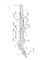
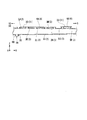
- FIG. 2 is a cross-sectional view taken along the line II-II in FIG.
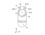
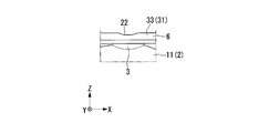
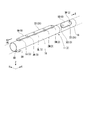
- FIG. 3 is a cross-sectional view taken along arrow III-III in FIG. 2. It is a IIIb direction arrow line view of FIG. 3A.
- the wind instrument 1 includes a tubular body 2, a sound hole tube 3, a mouthpiece 4 (blower), a bell 5, and a finger press plate 6.
- the mouthpiece 4 and the bell 5 are arranged at both ends in the longitudinal direction (X-axis direction) of the tube body 2.
- the mouthpiece 4 may be integrally formed with the tube body 2, for example, but in this embodiment, the mouthpiece 4 is detachably attached to the tube body 2.
- the mouthpiece 4 may be a single lead having a single thin plate-like lead 4A as shown in the drawing, but may be an air lead, a lip lead, or a double lead, for example.
- the longitudinal direction of the tube body 2 and the like corresponds to a straight direction from the mouthpiece 4 to the bell 5 as viewed from the player who plays the wind instrument 1.
- the left-right direction viewed from the performer is referred to as the width direction (Y-axis direction) of the tubular body 2 etc.
- the up-down direction viewed from the performer is referred to as the height direction (Z-axis direction) of the tubular body 2 etc.
- the pipe body 2 may be formed of, for example, any one of a wood material, a metal material, and a resin material, or may be formed of, for example, a material appropriately combining these materials.
- the tubular body 2 of the present embodiment includes a main pipe 11 in which a mouthpiece 4 and a bell 5 are arranged at both ends in the longitudinal direction, and a sub pipe 12 connected to the main pipe 11 so as to branch from the main pipe 11. .
- the main pipe 11 and the sub pipe 12 are each formed in a cylindrical shape having a constant inner diameter.
- the sub pipe 12 is connected to an end portion (first end portion 13) on the mouthpiece 4 side of the main pipe 11.
- the secondary pipe 12 is disposed on the upper side (Z-axis positive direction side) of the main pipe 11 and extends in the height direction and the longitudinal direction with respect to the main pipe 11. That is, the secondary pipe 12 does not extend in the width direction with respect to the main pipe 11. In the illustrated example, the secondary pipe 12 extends along the axis A1 (see FIG. 3A) of the main pipe 11, but this is not restrictive. Since the pipe body 2 includes the main pipe 11 and the sub pipe 12, the wind instrument 1 of the present embodiment has the same acoustic characteristics as when the pipe body 2 is a conical tube.
- the sound hole tube 3 constitutes the sound hole of the wind instrument 1 of the present embodiment, and is formed extending from the outer periphery of the main tube 11.
- the sound hole tube 3 has an inner opening end 21 that opens to the inside of the main tube 11 and an outer opening end 22 that opens to the outside of the main tube 11.
- the sound hole tube 3 is formed in a cylindrical shape having a constant inner diameter.
- a plurality of sound hole tubes 3 are arranged at intervals in the axial direction of the main tube 11.
- the position (axial position) of the inner opening end 21 of each sound hole tube 3 in the axial direction of the main tube 11 is set in consideration of the pitch of the wind instrument 1.
- the inner diameter dimension and the axial length of each sound hole tube 3 are individually set in consideration of the pitch and sound generation (for example, sound volume and sound quality) of the wind instrument 1. That is, some of the sound hole tubes 3 have different inner diameter dimensions and axial lengths of the sound hole tubes 3.
- the inner diameter dimensions of some of the sound hole tubes 3 (3A to 3E) are set to a size that allows the outer opening end 22 of the sound hole tube 3 to be closed with the fingers of the performer.
- the plurality of sound hole tubes 3 are arranged in a line in the longitudinal direction of the main tube 11. More specifically, the inner opening ends 21 of the plurality of sound hole tubes 3 are arranged at the same position in the circumferential direction of the main tube 11. Further, the direction in which the plurality of sound hole tubes 3 extend from the tube body 2 does not include the width direction of the main tube 11. In the present embodiment, the plurality of sound hole tubes 3 are all arranged in the upper portion of the main tube 11. Each of the plurality of sound hole tubes 3 has a portion extending in the height direction of the main tube 11 with respect to the main tube 11.
- the plurality of sound hole tubes 3 constitute a sound hole for a pitch operation (pitch for sound pitch) in which the pitch of the wind instrument 1 is changed by opening and closing.
- the wind instrument 1 of this embodiment includes a key mechanism 8 (key system).
- the first to fifth sound hole tubes 3A to 3E counted from the first end 13 side of the main tube 11 are directly opened and closed by the fingers of the performer.
- the first to third sound hole tubes 3A to 3C correspond to the index finger, middle finger and ring finger of the left hand of the performer, respectively
- the fourth and fifth sound hole tubes 3D and 3E correspond to the index finger and middle finger of the right hand, respectively.
- the sixth to ninth sound hole tubes 3F to 3I are opened and closed using the key mechanism 8 (key system).
- the key mechanism 8 is operated by the ring finger and little finger of the player's right hand.
- the main pipe 11 is also formed with a sound hole 14 (thumb sound hole 14 for thumb) that is opened and closed by the performer's thumb (thumb of the left hand).
- the thumb sound hole 14 is formed in a portion of the main pipe 11 closer to the mouthpiece 4 than the sound hole pipe 3 in the axial direction of the main pipe 11.
- the thumb sound hole 14 of the present embodiment opens to the lower side (Z-axis negative direction side) of the main pipe 11. Similar to the sound hole tube 3 described above, the thumb sound hole 14 is opened and closed to change the pitch of the wind instrument 1.
- the main tube 11 and some of the sound hole tubes 3 (3D, 3G) are bent so that the plurality of outer opening ends 22 are in positions corresponding to fingers that block the outer opening ends 22. .
- this point will be specifically described.
- the main pipe 11 of this embodiment meanders by being bent a plurality of times.
- the meandering direction of the main pipe 11 may be, for example, the width direction of the main pipe 11, but is the height direction of the main pipe 11 in this embodiment. That is, the main pipe 11 of this embodiment does not meander in the width direction. Since the main pipe 11 meanders, the length (linear length) of the main pipe 11 in the longitudinal direction of the main pipe 11 is shorter than the length (axial length) of the main pipe 11 in the axial direction of the main pipe 11. .
- the interval between the sound hole tubes 3 adjacent to each other in the longitudinal direction of the main tube 11 is smaller than the interval between the sound hole tubes 3 in the axial direction of the main tube 11.
- the portion of the main pipe 11 located between the fourth sound hole tube 3D and the fifth sound hole tube 3E is bent, so that the fourth sound hole tube 3D and the fifth sound hole tube 3D in the longitudinal direction of the main tube 11 are bent.
- the distance from the sound hole tube 3E is smaller than the distance from the fourth sound hole tube 3D to the fifth sound hole tube 3E in the axial direction of the main tube 11.
- the main pipe 11 is bent, in the longitudinal direction of the main pipe 11, the interval between the first sound hole pipe 3 ⁇ / b> A opened and closed with the left index finger and the thumb sound hole 14 opened and closed with the left thumb is The distance between the first sound hole tube 3A and the thumb sound hole 14 in the axial direction of the main tube 11 is smaller.
- the main pipe 11 meanders in the height direction. For this reason, the main pipe 11 has a relatively high position and a low position.
- a sound hole tube 3 (3A to 3C, 3E, 3F, 3H, 3I) having a relatively short axial length is disposed at a portion of the main tube 11 positioned relatively high.
- a sound hole tube 3 (3D, 3G) having a relatively long axial length is disposed at a portion of the main tube 11 positioned relatively low.
- the outer open ends 22 of the plurality of sound hole tubes 3 are located closer to each other in the height direction of the main tube 11 than in the case where the main tube 11 is not meandered.
- the outer opening ends 22 of the plurality of sound hole tubes 3 are positioned at the same height (same plane) by combining with the bending of the sound hole tube 3 described later.
- the hollow part 15 is formed in the site
- the hollow portion 15 is disposed near the fourth and fifth sound hole tubes 3D and 3E that are opened and closed by the index finger and middle finger of the right hand in the longitudinal direction of the main tube 11.
- the recess 15 may be positioned below the fifth sound hole tube 3E as illustrated in FIG. 2, but for example, the fourth and fifth sound hole tubes 3D and 3E in the longitudinal direction of the main tube 11. It may be located between. It is possible to arrange the thumb of the player's right hand in the recess 15.
- the bent sound hole tubes 3D and 3G have the curved tube portion 23 that changes the direction of the axis of the sound hole tubes 3D and 3G in the middle portion in the axial direction of the sound hole tubes 3D and 3G.
- the curved tube portion 23 may constitute part of the sound hole tubes 3D and 3G as illustrated in FIG. 2, or may constitute the whole sound hole tubes 3D and 3G, for example.
- the direction in which the sound hole tubes 3D and 3G are bent may be, for example, the width direction of the main tube 11, but is the longitudinal direction of the main tube 11 in this embodiment. That is, the sound hole tubes 3D and 3G of the present embodiment do not bend in the width direction of the main tube 11.
- the sound hole tube 3 (3D, 3G) having a relatively long axial length is bent so that the positions and orientations of the outer opening ends 22 of the plurality of sound hole tubes 3 are controlled by the wind instrument 1. It is preferably set in consideration of the properties and the like.
- the fourth sound hole tube 3D closed by the index finger of the right hand is bent so that the outer opening end 22 of the fourth sound hole tube 3D and the fifth sound hole tube blocked by the middle finger of the right hand are used.
- the 3E outer opening end 22 is located close to each other in the longitudinal direction and the height direction of the main pipe 11. That is, when the sound hole tube 3D is bent, the outer opening ends 22 of the plurality of sound hole tubes 3D and 3E that are closed by fingers of the same hand are positioned close to each other.
- the direction of the inner opening end 21 of the fourth sound hole tube 3D is different from the inner opening ends 21 of the other sound hole tubes 3 (3A, 3B, 3C, 3E, etc.), and is higher in the height direction of the main tube 11. In contrast, it is inclined in the longitudinal direction. However, since the fourth sound hole tube 3D is bent, the direction of the outer opening end 22 of the fourth sound hole tube 3D is the same as that of the outer opening end 22 of the other sound hole tubes 3. It is on the upper side in the height direction.
- the fourth sound hole tube 3D may be bent a plurality of times, for example, but is bent only once in the present embodiment.
- the seventh sound hole tube 3G that is opened and closed using the key mechanism 8 is bent, the outer opening end 22 of the seventh sound hole tube 3G and the sixth and eighth sound hole tubes 3F.
- the distance from the outer opening end 22 of 3H is adjusted in consideration of the configuration of the key mechanism 8.
- the seventh sound hole tube 3D meanders by being bent a plurality of times.
- the main pipe 11 and the sound hole pipe 3 are bent so that the positions of the outer opening ends 22 of the plurality of sound hole pipes 3 in the height direction of the main pipe 11 coincide with each other.
- the outer opening end 22 of the sound hole tubes 3A to 3E that are directly opened and closed by fingers and the outer opening end 22 of the sound hole tubes 3F to 3I that are opened and closed using the key mechanism 8 are used.
- the positions in the height direction are different from each other, they may coincide, for example.
- the finger pressing plate 6 extends from the outer opening end 22 of the sound hole tube 3 to the outside of the sound hole tube 3 in the radial direction of the sound hole tube 3. Yes. That is, the finger pressing plate 6 is a flange formed at the outer opening end 22 of the sound hole tube 3.
- the finger pressing plate 6 is arranged with an interval with respect to the outer periphery of the main pipe 11.
- the outer opening end 22 of the sound hole tube 3 faces the upper side of the main tube 11. For this reason, the extending direction of the finger pressing plate 6 is the longitudinal direction and the width direction of the main pipe 11 orthogonal to the height direction of the main pipe 11.
- a common finger pressing plate 6 is provided for the plurality of sound hole tubes 3. That is, the same finger pressing plate 6 is provided for the plurality of sound hole tubes 3.
- the finger pressing plate 6 is formed in a strip shape extending in the longitudinal direction of the main tube 11.
- the dimension (width dimension) of the finger pressing plate 6 in the width direction of the main pipe 11 is set so as not to protrude from both ends in the width direction of the main pipe 11 in consideration of operability by the player. Yes.
- the finger pressing plate 6 may be provided for at least the sound hole tubes 3A to 3E that are directly opened and closed by fingers, but in this embodiment, as shown in FIG. It is also provided for the hole tubes 3F to 3I.
- the finger pressing plate 6 has a surface (opening surface 31) where the outer opening end 22 of the sound hole tube 3 opens.
- a region where the outer opening end 22 of the sound hole tube 3 opened and closed by the key mechanism 8 is disposed (hereinafter referred to as a key opening surface 32) is a flat surface. Is formed.
- a region (hereinafter referred to as a finger opening surface 33) in which the outer opening end 22 of the sound hole tube 3 that is directly opened and closed by fingers is arranged is shown in FIG. 3A. As shown in FIG.
- the finger opening surface 33 is formed in a curved surface that is curved in a convex shape when viewed from the longitudinal direction of the main tube 11 (see FIG. 3A) and is not curved when viewed in the width direction of the main tube 11 (see FIG. 3B). ing. Thereby, the outer opening end 22 of the sound hole tube 3 is formed with a hollow shape that allows fingers to enter as shown in FIG. 3B.
- the sound hole is configured by the sound hole tube 3, so that the thickness of the tube wall of the tube body 2 can be reduced without considering the length of the sound hole. Can be set. Thereby, the tube wall of the tube body 2 can be formed thinly. Accordingly, resources for configuring the wind instrument 1 can be saved, and the weight of the wind instrument 1 can be reduced.
- the performer can easily determine whether or not the outer opening end 22 of the sound hole tube 3 is properly closed with fingers.
- this point will be specifically described.
- the performer's fingers touch not only the inner edge of the outer open end 22 but also the outer edge. All of these feelings are transmitted to the fingers of the performer. For this reason, it is difficult for the performer to determine whether the outer opening end 22 of the sound hole tube 3 is properly closed.
- the finger pressing plate 6 when there is the finger pressing plate 6, the finger does not touch the outer edge of the outer opening end 22 when the outer opening end 22 of the sound hole tube 3 is closed with the fingers. This makes it easier for the performer to grasp the inner edge of the outer opening end 22 of the sound hole tube 3 by finger sensation. That is, the performer can easily determine whether or not the outer opening end 22 of the sound hole tube 3 is properly closed with the fingers, with the sense of the fingers.
- the finger pressing plate 6 when the performer's finger does not block the outer opening end 22 of the sound hole tube 3, the finger is opened on the opening surface 31 of the finger pressing plate 6 (particularly the finger). Can also be placed on the opening surface 33). For this reason, the performer can easily move his / her fingers from a position where the outer opening end 22 of the sound hole tube 3 is not blocked to a position where it is closed.
- the wind instrument 1 of the present embodiment includes the finger pressing plate 6, the player can easily perform the operation of closing the outer opening end 22 of the sound hole tube 3 with his / her fingers.
- the finger press plate 6 when the performer tries to block the outer opening end 22 of the sound hole tube 3 with his / her finger, the player's finger is detached from the outer opening end 22 of the sound hole tube 3.
- the fingers are positioned on the outer periphery of the sound hole tube 3. In this case, the finger must be lifted from the outer periphery of the sound hole tube 3 and then moved to a position where the outer opening end 22 of the sound hole tube 3 is closed, and the operability of the wind instrument 1 is not necessarily good.
- the finger pressing plate 6 makes it possible to ensure the operability of the wind instrument 1 by the performer.
- the same finger pressing plate 6 is provided for the plurality of sound hole tubes 3.
- the edge portion (the portion corresponding to the edge of the finger opening surface 33) of the finger pressing plate 6 in the extending direction is not positioned between the outer opening ends 22 of the adjacent sound hole tubes 3.
- toe will touch the edge part of the extending direction front-end
- the performer can more easily grasp whether or not the outer opening end 22 of the sound hole tube 3 is properly closed with fingers.
- the gap between the adjacent sound hole tubes 3 is covered by the finger pressing plate 6. For this reason, even if the player's finger is detached from the outer opening end 22 of the sound hole tube 3 when the player tries to close the outer opening end 22 of the sound hole tube 3 with his / her fingers, It is possible to prevent fingers from entering between adjacent sound hole tubes 3. This eliminates the need to lift the finger even if the performer's finger is detached from the outer opening end 22 of the sound hole tube 3, and the player can easily perform the operation of closing the outer opening end 22 of the sound hole tube 3 with his / her finger. Can be done. From the above, since the same finger pressing plate 6 is provided for the plurality of sound hole tubes 3, the operability of the wind instrument 1 by the performer can be ensured more favorably.
- the tube 2, the sound hole tube 3 and the finger pressing plate 6 of the wind instrument 1 are manufactured by resin molding. Compared with the case where the finger pressing plate 6 is provided for each sound hole tube 3, the shape of the mold can be simplified. Thereby, the wind instrument 1 can be manufactured easily. In addition, the manufacturing cost of the wind instrument 1 can be reduced.
- the finger opening surface 33 of the finger pressing plate 6 is formed in a curved surface, so that the player can correctly and easily open the outer opening end 22 of the sound hole tube 3 with the fingers. Can be blocked. More specifically, by forming the finger opening surface 33 of the finger pressing plate 6 into a curved surface, a hollow shape that allows fingers to enter the outer opening end 22 of the sound hole tube 3 is formed. For this reason, the performer can close the outer opening end 22 of the sound hole tube 3 correctly and easily by letting the fingers enter the outer opening end 22 having a hollow shape.
- the wind instrument 1 of the present embodiment it is possible to easily ensure both the acoustic performance of the wind instrument 1 and the operability of the wind instrument 1.
- the pitch and pronunciation for example, volume and sound quality
- the arrangement of the plurality of sound holes with respect to the main pipe 11 is adjusted in consideration of the operability of the wind instrument 1.
- the main tube 11 and the sound hole tube 3 are bent so that the adjustment of the pitch is not hindered. can do. Further, regarding the pronunciation of the wind instrument 1, since it is not necessary to use the diameter of the sound hole as the main adjustment of the pitch described above, the inner diameter of the sound hole tube 3 (the diameter of the sound hole) can be effectively utilized. it can.
- the pitch of the wind instrument 1 can be adjusted by changing the inner diameter of the sound hole tube 3, but in this embodiment, the sound hole tube is not hindered by the operability of the wind instrument 1.
- the length dimension of 3 can be freely changed.
- the pitch of the wind instrument 1 can be sufficiently adjusted by changing the length dimension of the sound hole tube 3 instead of changing the inner diameter dimension of the sound hole tube 3. .
- the sound of the wind instrument 1 is adjusted by changing the inner diameter dimension of the sound hole tube 3, but in the wind instrument 1 of the present embodiment, the change in the inner diameter dimension of the sound hole tube 3 is not used for adjusting the pitch. Therefore, it is possible to prevent the sound adjustment from being affected by the pitch adjustment.
- the wind instrument 1 of the present embodiment it is possible to relax restrictions on the adjustment of the pitch, the adjustment of the sound generation, and the adjustment of the sound hole arrangement considering the operability. Therefore, both the acoustic performance of the wind instrument 1 and the operability of the wind instrument 1 can be easily ensured.
- the plurality of sound hole tubes 3 have portions extending in the height direction of the main tube 11 with respect to the main tube 11, and the meandering direction of the main tube 11 is the height of the main tube 11. Parallel to the direction. For this reason, the positions of the inner opening ends 21 of the plurality of sound hole tubes 3 can be separated from each other in the height direction of the main tube 11. Thereby, even if the axial direction lengths of the plurality of sound hole tubes 3 are different from each other, the outer opening ends 22 of the plurality of sound hole tubes 3 can be brought close to each other in the height direction of the main tube 11. As a result, the outer open ends 22 of the plurality of sound hole tubes 3 can be easily closed with a plurality of fingers. That is, the operability of the wind instrument 1 can be easily ensured.
- the meandering direction of the main pipe 11 is parallel to the height direction of the main pipe 11, so that the first sound hole pipe 3A that is opened and closed with the left index finger and the left thumb is opened and closed.
- the distance from the thumb sound hole 14 can also be reduced. Therefore, when both the first sound hole tube 3A and the thumb sound hole 14 are closed, the tube body 2 can be gripped by the left thumb and the index finger. That is, the player can stably hold the wind instrument 1 and the operability of the wind instrument 1 can be improved.
- the main mechanism 11 and the sound hole tube 3 are bent, and the interval between the outer opening ends 22 of the sound hole tube 3 is reduced, so that the key mechanism 8 can be configured compactly.
- the number of outer open ends 22 of the sound hole tube 3 that can be directly closed with fingers can be increased, the number of sound hole tubes 3 that are opened and closed using the key mechanism 8 can be reduced. it can. That is, the number of operators 41 (keys) of the key mechanism 8 can be reduced. Further, since the length of the operation element 41 of the key mechanism 8 can be set short, the reliability of the wind instrument 1 can be improved.
- the hollow part 15 is formed in the site
- the bent sound hole tube 3 since the bent sound hole tube 3 has the curved tube portion 23, the outer opening end 22 of the sound hole tube 3 is freely and appropriately disposed with respect to the inner opening end 21. can do. That is, the operability of the wind instrument 1 can be easily ensured.
- the main pipe 11 meanders only in the height direction, and the plurality of sound hole pipes 3 extend only from the main pipe 11 in the height direction and the longitudinal direction.
- a plurality of sound hole tubes 3 are arranged in a line in the longitudinal direction of the main tube 11.
- the shape of the structure including the main pipe 11 and the plurality of sound hole pipes 3 can be made symmetrical with respect to the center in the width direction of the main pipe 11.
- the wind instrument of the present embodiment differs from the wind instrument 1 of the first embodiment only in a part of the configuration, and the other configurations are the same.
- the same components as those in the first embodiment are denoted by the same reference numerals, and the description thereof is omitted.
- the wind instrument 100 of the present embodiment includes a tubular body 2, a sound hole tube 3, and a finger press plate 6 similar to the wind instrument 1 of the first embodiment. Moreover, in the wind instrument 100 of this embodiment, the tube body 2 and the sound hole tube 3 are integrally formed like the first embodiment. However, in the wind instrument 100 of the present embodiment, the finger pressing plate 6 is formed separately from the tube body 2 and the sound hole tube 3. Hereinafter, the wind instrument 100 of this embodiment is demonstrated concretely.
- the main pipe 11 of the tubular body 2 has a first through hole 101 that constitutes a sound hole of the wind instrument 100.
- the first through hole 101 penetrates from the inside to the outside of the main pipe 11.
- the sound hole tube 3 is integrally formed on the outer periphery of the main tube 11.
- the sound hole tube 3 constitutes a sound hole of the wind instrument 100 together with the first through hole 101 of the main tube 11.
- the structure including the main tube 11 and the sound hole tube 3 is constituted by a pair of divided structures 102 and 103 divided so as to divide the sound hole of the wind instrument 100.
- the boundary 104 between the pair of divided structural bodies 102 and 103 is included in the same virtual plane VP together with the axis A1 of the main pipe 11 and the axis of the sound hole.
- the main tube 11 does not meander in the width direction (Y-axis direction) of the tube body 2 as in the first embodiment.
- the virtual plane VP is a plane orthogonal to the width direction of the tubular body 2.
- the boundary 104 between the pair of divided structural bodies 102 and 103 is located at the center in the width direction of the main pipe 11. Therefore, the pair of divided structural bodies 102 and 103 are formed in a symmetrical shape with respect to the center in the width direction of the main pipe 11.
- the tube body 2 of the present embodiment extends in the height direction (Z-axis direction) and the longitudinal direction (X-axis direction) of the tube body 2 with respect to the main tube 11, as in the first embodiment. It has a secondary pipe 12 (see FIGS. 1 and 2) that does not extend in the width direction of the body 2.
- the structure containing the main pipe 11, the sound hole pipe 3, and the sub pipe 12 may be comprised by a pair of division
- the finger pressing plate 6 has a second through hole 105 that penetrates in the thickness direction.
- the second through hole 105 constitutes a sound hole of the wind instrument 100 together with the first through hole 101 of the main pipe 11 and the sound hole pipe 3.
- the finger pressing plate 6 is arranged on the outer periphery of the main pipe 11 so as to cover the boundary 104 between the pair of divided structural bodies 102 and 103.
- the finger pressing plate 6 of the present embodiment is arranged at the outer opening end 22 of the sound hole tube 3 so as to cover the boundary 104 between the pair of divided structural bodies 102 and 103 appearing at the outer opening end 22 of the sound hole tube 3. Yes.
- the finger pressing plate 6 arranged in this way extends outward from the outer opening end 22 of the sound hole tube 3 in the radial direction of the sound hole tube 3 as in the first embodiment.
- the same effects as in the first embodiment can be obtained.
- the structural body including the tubular body 2 and the sound hole tube 3 is constituted by a pair of divided structural bodies 102 and 103.
- a pair of division structure 102,103 can be shape
- the structure including the tube 2 and the sound hole tube 3 is divided into a pair of divided structures 102 and 103 so as to divide the sound hole of the wind instrument 100.
- the inner surface of a sound hole can be processed easily.
- an undercut structure in which the inner diameter of the sound hole gradually increases toward the inner side of the main pipe 11 can be easily formed at the end of the sound hole located inside the main pipe 11.
- the formation of the undercut structure is useful for improving the acoustic performance of the wind instrument 100 such as the pitch. That is, according to the wind instrument 100 of the present embodiment, the acoustic performance of the wind instrument 100 can be easily ensured.
- the boundary 104 between the pair of divided structural bodies 102 and 103 is covered with the finger pressing plate 6. Therefore, when the performer plays the wind instrument 100, the performer's finger that opens and closes the sound hole only touches the finger opening surface 33 of the finger press plate 6, and the boundary between the pair of divided components 102 and 103 104 is not touched. As a result, the performer can play the wind instrument 100 smoothly.
- this point will be specifically described.
- a minute step may appear at the boundary 104 between the pair of divided structural bodies 102 and 103. For this reason, if a performer's finger touches the level
- the boundary 104 between the pair of divided structural bodies 102 and 103 is covered with the finger pressing plate 6, so that the player can smoothly play the wind instrument 100 without feeling uncomfortable or stressed. Can be performed.
- the wind instrument may include only the tube body 2 and the finger press plate 6 without including the sound hole tube 3.
- the finger pressing plate 6 is directly disposed on the outer periphery of the main pipe 11. Even with such a configuration, the same effects as those of the second embodiment described above can be obtained.
- the wind instrument of the present invention is not limited to the one including the key mechanism 8 and can be applied to a wind instrument of a type in which all the sound hole tubes 3 are directly opened and closed with fingers as shown in FIGS.
- the sound hole tube 3 may include a skew tube portion that extends straight in a direction in which the axis of the sound hole tube 3 is inclined with respect to the radial direction of the main tube 11, for example.
- the axis of the sound hole tube 3 extends in a direction inclined with respect to the radial direction of the main tube 11 so that the outer opening ends 22 of the plurality of sound hole tubes 3 are in positions corresponding to the fingers that block them.
- the sound hole tube 3 may have both a skewed tube portion and a curved tube portion 23 similar to the above embodiment, for example. Further, the main pipe 11 and the sound hole pipe 3 do not have to be bent or inclined as shown in FIGS.
- the plurality of sound hole tubes 3 are not limited to be arranged in a line in the longitudinal direction of the main tube 11, and may be positioned so as to be shifted from each other in the circumferential direction of the main tube 11 as shown in FIG. 7, for example. That is, the inner opening ends 21 of the plurality of sound hole tubes 3 may be arranged at different positions in the circumferential direction of the main tube 11, for example. For example, as shown in FIG. 6, the outer opening ends 22 of the plurality of sound hole tubes 3 may be arranged at different positions in the height direction of the main tube 11. The directions of the outer opening ends 22 of the plurality of sound hole tubes 3 may be different from each other.
- the finger opening surface 33 of the finger pressing plate 6 may be formed in a curved surface that inclines upward as the distance from the outer opening end 22 of the sound hole tube 3 increases, for example.
- a hollow shape that allows the fingers to enter the outer opening end 22 of the sound hole tube 3 is formed by the finger opening surface 33 formed in a curved surface.
- the finger opening surface 33 (opening surface 31) of the finger pressing plate 6 may be a flat surface as shown in FIGS.
- the wind instrument of the present invention may include a plurality of finger pressing plates 6 as shown in FIGS.
- Two finger pressing plates 6 (6A, 6B) are arranged on the outer periphery of the main pipe 11 of the wind instrument illustrated in FIGS. 6 and 7, the first finger pressing plate 6A is provided for the first to fifth sound hole tubes 3J to 3N counted from the first end 13 side of the main tube 11, and the second finger
- the pressing plate 6B is provided for the sixth and seventh sound hole tubes 3O and 3P
- the number of the sound hole tubes 3 corresponding to each finger pressing plate 6 may be arbitrary.
- the first finger pressing plate 6A is provided for the sound hole tube 3 that is opened and closed by the left hand finger
- the second finger pressing plate 6B is provided for the sound hole tube 3 that is opened and closed by the right hand finger. Also good.
- each finger pressing plate 6 is formed in a simple shape (a flat plate in FIG. 6) even when the axial lengths of the sound hole tubes 3 are different. be able to.
- the finger pressing plate 6 may be individually provided for the plurality of sound hole tubes 3, for example.
- the size of the opening surface 31 of the finger pressing plate 6 around the outer opening end 22 of the sound hole tube 3 may be arbitrary. For example, even if the finger of the performer is placed on the opening surface 31, Is preferably set so as not to touch the edge of the finger pressing plate 6 in the extending direction.
- the main tube 11 includes two or more tube portions 16 that are rotatably connected to each other, and the sound hole tube 3 and the finger press plate 6. May be disposed in each tubular body portion 16.
- the position (orientation) of the outer opening end 22 of the sound hole tube 3 disposed in the two tube portions 16 is set in the circumferential direction of the main tube 11 by rotating the two tube portions 16 with each other. It can be changed relatively. Thereby, the position of the outer opening end 22 of the plurality of sound hole tubes 3 can be appropriately adjusted according to the size and length of the fingers of the performer.
- the thumb sound hole 14 may be constituted by a sound hole tube 30 extending from the outer periphery of the main tube 11 in the same manner as the pitch sound hole. Further, the sound hole tube 30 constituting the thumb sound hole 14 extends from the outer opening end of the sound hole tube 30 to the outside of the sound hole tube 30 in the radial direction of the sound hole tube 30 in the same manner as in the above embodiment.
- a finger press plate 60 may be provided.
- the tubular body 2 of the wind instrument may be arbitrarily configured. That is, the tube body 2 may be configured by only the main tube 11 without including the secondary tube 12, for example.
- the tube body 2 (main tube 11) is not limited to a cylindrical shape, and may be formed in a conical tube shape, for example.
- the tubular body 2 (main tube 11) of the wind instrument illustrated in FIG. 6 is formed in a conical tubular shape whose inner diameter is reduced from the mouthpiece 4 side toward the bell 5 side.
Landscapes
- Physics & Mathematics (AREA)
- Engineering & Computer Science (AREA)
- Acoustics & Sound (AREA)
- Multimedia (AREA)
- Auxiliary Devices For Music (AREA)
- Electrophonic Musical Instruments (AREA)
Abstract
管楽器は、管体と、管体の外周から延びて形成され、管体の内側に開口する内側開口端、及び、管体の外側に開口する外側開口端を有する音孔管と、音孔管の径方向において音孔管の外側開口端から音孔管の外側に延出している指押さえ板と、を備える。
Description
本発明は、管楽器に関する。
本願は、2015年9月30日に出願された特願2015-192842号に基づき優先権を主張し、その内容をここに援用する。
本願は、2015年9月30日に出願された特願2015-192842号に基づき優先権を主張し、その内容をここに援用する。
従来、管体にその管壁を貫通する複数の音孔を形成した管楽器がある。管楽器では、その音程や音質を適切に設定するため、音孔の長さ(軸方向長さ)を確保することが行われる。特許文献1には、音程や音質が良好に得られるように、音孔の貫通方向を管体の軸線に対して傾斜させた管楽器が開示されている。
しかしながら、従来の管楽器では、音孔が管体の管壁を貫通して形成されているため、音孔の長さを確保するために、管壁の厚みが大きくなってしまう。このため、管楽器を構成するために多くの資源(例えば木材材料や樹脂材料)が必要となり、また、管楽器の重量が重くなる、という問題がある。
本発明は、上述した事情に鑑みてなされたものであって、音孔の長さを確保しつつ、資源の節約や軽量化を図ることが可能な管楽器を提供することを目的とする。
本発明の一態様の管楽器は、管体と、前記管体の外周から延びて形成され、前記管体の内側に開口する内側開口端、及び、前記管体の外側に開口する外側開口端を有する音孔管と、前記音孔管の径方向において前記音孔管の外側開口端から前記音孔管の外側に延出している指押さえ板と、を備える。
本発明の他の態様の管楽器は、音孔を構成する第一貫通孔を有する管体と、前記管体の外周上に配され、前記第一貫通孔と共に音孔を構成する第二貫通孔を有する指押さえ板と、を備え、前記管体が、前記音孔を分断するように分割された一対の分割構成体によって構成され、前記指押さえ板が、前記一対の分割構成体の境界を覆うように前記管体の外周上に配されている。
本発明によれば、管楽器における音孔の長さを確保しつつ、管楽器を構成する資源の節約や軽量化を図ることができる。また、演奏者による管楽器の操作性を確保することができる。
〔第一実施形態〕
以下、図1,図2,図3A,図3Bを参照して本発明の第一実施形態について説明する。
図1,2に示すように、本実施形態の管楽器1は、管体2と、音孔管3と、マウスピース4(吹口)と、ベル5と、指押さえ板6と、を備える。マウスピース4とベル5は、管体2の長手方向(X軸方向)の両端に配されている。マウスピース4は、例えば管体2に一体に形成されてもよいが、本実施形態では、管体2に対して着脱可能に装着される。マウスピース4は、図示例のように薄板状のリード4Aを一枚備えるシングルリードであってもよいが、例えばエアリード、リップリード、ダブルリードであってよい。
本実施形態において、管体2等の長手方向は、管楽器1を演奏する演奏者から見てマウスピース4からベル5に向かう真っ直ぐな方向に対応する。以下の説明では、演奏者から見た左右方向を管体2等の幅方向(Y軸方向)と呼び、演奏者から見た上下方向を管体2等の高さ方向(Z軸方向)と呼ぶことがある。
以下、図1,図2,図3A,図3Bを参照して本発明の第一実施形態について説明する。
図1,2に示すように、本実施形態の管楽器1は、管体2と、音孔管3と、マウスピース4(吹口)と、ベル5と、指押さえ板6と、を備える。マウスピース4とベル5は、管体2の長手方向(X軸方向)の両端に配されている。マウスピース4は、例えば管体2に一体に形成されてもよいが、本実施形態では、管体2に対して着脱可能に装着される。マウスピース4は、図示例のように薄板状のリード4Aを一枚備えるシングルリードであってもよいが、例えばエアリード、リップリード、ダブルリードであってよい。
本実施形態において、管体2等の長手方向は、管楽器1を演奏する演奏者から見てマウスピース4からベル5に向かう真っ直ぐな方向に対応する。以下の説明では、演奏者から見た左右方向を管体2等の幅方向(Y軸方向)と呼び、演奏者から見た上下方向を管体2等の高さ方向(Z軸方向)と呼ぶことがある。
管体2は、例えば木材材料、金属材料、樹脂材料のいずれか一つの材料によって形成されてもよいし、例えばこれらの材料を適宜組み合わせた材料によって形成されてもよい。
本実施形態の管体2は、長手方向の両端にマウスピース4、ベル5が配されている主管11と、主管11から分岐するように主管11に接続されている副管12と、を備える。
主管11及び副管12は、それぞれ内径寸法が一定の円筒状に形成されている。副管12は、主管11のうちマウスピース4側の端部(第一端部13)に接続されている。本実施形態において、副管12は、主管11の上側(Z軸正方向側)の部位に配されており、主管11に対して高さ方向や長手方向に延びている。すなわち、副管12は主管11に対して幅方向に延びていない。図示例において、副管12は主管11の軸線A1(図3A参照)に沿うように延びているが、これに限ることは無い。
管体2が主管11と副管12とを備えることで、本実施形態の管楽器1は、管体2が円錐管状である場合と同様の音響特性を有する。
本実施形態の管体2は、長手方向の両端にマウスピース4、ベル5が配されている主管11と、主管11から分岐するように主管11に接続されている副管12と、を備える。
主管11及び副管12は、それぞれ内径寸法が一定の円筒状に形成されている。副管12は、主管11のうちマウスピース4側の端部(第一端部13)に接続されている。本実施形態において、副管12は、主管11の上側(Z軸正方向側)の部位に配されており、主管11に対して高さ方向や長手方向に延びている。すなわち、副管12は主管11に対して幅方向に延びていない。図示例において、副管12は主管11の軸線A1(図3A参照)に沿うように延びているが、これに限ることは無い。
管体2が主管11と副管12とを備えることで、本実施形態の管楽器1は、管体2が円錐管状である場合と同様の音響特性を有する。
音孔管3は、本実施形態の管楽器1の音孔を構成するものであり、主管11の外周から延びて形成されている。音孔管3は、主管11の内側に開口する内側開口端21と、主管11の外側に開口する外側開口端22と、を有する。音孔管3は、内径寸法が一定の円筒状に形成されている。
音孔管3は、主管11の軸方向に間隔をあけて複数配列されている。
主管11の軸方向における各音孔管3の内側開口端21の位置(軸方向位置)は、管楽器1の音程を考慮して設定されている。各音孔管3の内径寸法や軸方向長さは、管楽器1の音程や発音(例えば音量や音質など)を考慮して個別に設定されている。すなわち、複数の音孔管3には、音孔管3の内径寸法や軸方向長さが互いに異なっているものがある。
また、一部の音孔管3(3A~3E)の内径寸法は、演奏者の手指で音孔管3の外側開口端22を塞ぐことが可能な大きさに設定されている。
主管11の軸方向における各音孔管3の内側開口端21の位置(軸方向位置)は、管楽器1の音程を考慮して設定されている。各音孔管3の内径寸法や軸方向長さは、管楽器1の音程や発音(例えば音量や音質など)を考慮して個別に設定されている。すなわち、複数の音孔管3には、音孔管3の内径寸法や軸方向長さが互いに異なっているものがある。
また、一部の音孔管3(3A~3E)の内径寸法は、演奏者の手指で音孔管3の外側開口端22を塞ぐことが可能な大きさに設定されている。
本実施形態において、複数の音孔管3は、主管11の長手方向に一列に並べられている。より具体的には、複数の音孔管3の内側開口端21が、主管11の周方向において互いに同じ位置に配されている。また、複数の音孔管3が管体2から延びる方向には、主管11の幅方向が含まれない。本実施形態において、複数の音孔管3は、いずれも主管11の上側の部位に配されている。
また、複数の音孔管3は、いずれも主管11に対して主管11の高さ方向に延びる部位を有する。一部の音孔管3(3A~3C、3E、3F、3H、3I)は、全体が主管11の高さ方向に真っ直ぐに延びている。残りの音孔管3(3D、3G)は、後述するように曲がっているものの、主管11の高さ方向に延びる部位を有する。
これら複数の音孔管3は、開閉されることで管楽器1の音程が変わる音程操作用の音孔(音程用音孔)を構成する。
また、複数の音孔管3は、いずれも主管11に対して主管11の高さ方向に延びる部位を有する。一部の音孔管3(3A~3C、3E、3F、3H、3I)は、全体が主管11の高さ方向に真っ直ぐに延びている。残りの音孔管3(3D、3G)は、後述するように曲がっているものの、主管11の高さ方向に延びる部位を有する。
これら複数の音孔管3は、開閉されることで管楽器1の音程が変わる音程操作用の音孔(音程用音孔)を構成する。
本実施形態では、上記した音孔管3の数が9個であり、全ての音孔管3の開閉を演奏者の手指で直接開閉することが難しい。このため、本実施形態の管楽器1は、鍵機構8(キーシステム)を備える。
9個の音孔管3のうち主管11の第一端部13側から数えて1番目~5番目の音孔管3A~3Eは、演奏者の手指で直接開閉される。1番目~3番目の音孔管3A~3Cは、それぞれ演奏者の左手の人差し指、中指、薬指に対応し、4番目、5番目の音孔管3D、3Eは、それぞれ右手の人差し指、中指に対応する。
一方、6番目~9番目の音孔管3F~3Iは、鍵機構8(キーシステム)を利用して開閉される。鍵機構8は、演奏者の右手の薬指と小指によって操作される。
9個の音孔管3のうち主管11の第一端部13側から数えて1番目~5番目の音孔管3A~3Eは、演奏者の手指で直接開閉される。1番目~3番目の音孔管3A~3Cは、それぞれ演奏者の左手の人差し指、中指、薬指に対応し、4番目、5番目の音孔管3D、3Eは、それぞれ右手の人差し指、中指に対応する。
一方、6番目~9番目の音孔管3F~3Iは、鍵機構8(キーシステム)を利用して開閉される。鍵機構8は、演奏者の右手の薬指と小指によって操作される。
主管11には、演奏者の親指(左手の親指)で開閉される音孔14(親指用音孔14)も形成されている。親指用音孔14は、主管11のうち主管11の軸方向において音孔管3よりもマウスピース4側の部位に形成されている。本実施形態の親指用音孔14は、主管11の下側(Z軸負方向側)に開口している。親指用音孔14は、前述した音孔管3と同様に、開閉されることで管楽器1の音程を変える。
本実施形態の管楽器1では、複数の外側開口端22が外側開口端22を塞ぐ手指に対応した位置となるように、主管11及び一部の音孔管3(3D、3G)が曲がっている。以下、この点について具体的に説明する。
本実施形態の主管11は、複数回曲がっていることで蛇行している。主管11の蛇行方向は、例えば主管11の幅方向であってもよいが、本実施形態では主管11の高さ方向となっている。すなわち、本実施形態の主管11は幅方向に蛇行しない。主管11が蛇行していることで、主管11の長手方向における主管11の長さ(直線長さ)が主管11の軸方向における主管11の長さ(軸方向長さ)よりも短くなっている。
また、主管11が曲がっていることで、主管11の長手方向において互いに隣り合う音孔管3同士の間隔が、主管11の軸方向における音孔管3同士の間隔よりも小さくなっている。例えば、4番目の音孔管3Dと5番目の音孔管3Eとの間に位置する主管11の部位が曲がっていることで、主管11の長手方向における4番目の音孔管3Dと5番目の音孔管3Eとの間隔が、主管11の軸方向における4番目の音孔管3Dと5番目の音孔管3Eとの間隔よりも小さくなっている。
また、主管11が曲がっていることで、主管11の長手方向において、左手の人差し指で開閉される1番目の音孔管3Aと左手の親指で開閉される親指用音孔14との間隔が、主管11の軸方向における1番目の音孔管3Aと親指用音孔14との間隔よりも小さくなっている。
また、本実施形態では、主管11が高さ方向に蛇行している。このため、主管11には、相対的に高く位置する部位と、低く位置する部位とがある。
相対的に高く位置する主管11の部位には、軸方向長さが比較的短い音孔管3(3A~3C、3E、3F、3H、3I)が配されている。一方、相対的に低く位置する主管11の部位には、軸方向長さが比較的長い音孔管3(3D、3G)が配されている。これにより、複数の音孔管3の外側開口端22は、主管11を蛇行させない場合と比較して、主管11の高さ方向について互いに近くに位置している。本実施形態では、後述する音孔管3の曲がりと組み合わせることで、複数の音孔管3の外側開口端22が同一の高さ(同一平面)に位置する。
相対的に高く位置する主管11の部位には、軸方向長さが比較的短い音孔管3(3A~3C、3E、3F、3H、3I)が配されている。一方、相対的に低く位置する主管11の部位には、軸方向長さが比較的長い音孔管3(3D、3G)が配されている。これにより、複数の音孔管3の外側開口端22は、主管11を蛇行させない場合と比較して、主管11の高さ方向について互いに近くに位置している。本実施形態では、後述する音孔管3の曲がりと組み合わせることで、複数の音孔管3の外側開口端22が同一の高さ(同一平面)に位置する。
また、本実施形態では、主管11が高さ方向に蛇行することで、主管11の下側(Z軸負方向側)の部位に窪み部15が形成されている。窪み部15は、主管11の長手方向において右手の人差し指や中指で開閉される4番目、5番目の音孔管3D、3Eの近くに配されている。窪み部15は、図2に例示するように5番目の音孔管3Eの下側に位置してもよいが、例えば主管11の長手方向において4番目、5番目の音孔管3D、3Eの間に位置してもよい。
窪み部15には、演奏者の右手の親指を配することが可能である。
窪み部15には、演奏者の右手の親指を配することが可能である。
本実施形態の管楽器1では、他の音孔管3(3A~3C、3E、3F、3H、3I)と比較して軸方向長さが長く設定されている音孔管3(3D、3G)が曲がっている。すなわち、軸方向長さが比較的短い音孔管3(3A~3C、3E、3F、3H、3I)は、主管11から高さ方向(主管11の径方向)に真っ直ぐに延びている。また、軸方向長さが比較的長い音孔管3(3D、3G)は、主管11から曲がりながら高さ方向(主管11の径方向)に延びている。
本実施形態では、曲がっている音孔管3D、3Gが、音孔管3D、3Gの軸方向の中途部において音孔管3D、3Gの軸線の向きを変える湾曲管部23を有する。湾曲管部23は、図2に例示するように音孔管3D、3Gの一部を構成してもよいし、例えば音孔管3D、3Gの全体を構成してもよい。
音孔管3D、3Gが曲がる向きは、例えば主管11の幅方向であってもよいが、本実施形態では主管11の長手方向となっている。すなわち、本実施形態の音孔管3D、3Gは、主管11の幅方向に曲がらない。
音孔管3D、3Gが曲がる向きは、例えば主管11の幅方向であってもよいが、本実施形態では主管11の長手方向となっている。すなわち、本実施形態の音孔管3D、3Gは、主管11の幅方向に曲がらない。
本実施形態では、軸方向長さが比較的長い音孔管3(3D、3G)が曲がっていることで、複数の音孔管3の外側開口端22の位置や向きが、管楽器1の操作性等を考慮して好適に設定されている。
例えば、右手の人差し指で塞がれる4番目の音孔管3Dが曲がっていることで、4番目の音孔管3Dの外側開口端22と、右手の中指で塞がれる5番目の音孔管3Eの外側開口端22とが、主管11の長手方向及び高さ方向において互いに近くに位置している。すなわち、音孔管3Dが曲がっていることで、同じ手の手指で塞がれる複数の音孔管3D、3Eの外側開口端22が互いに近くに位置している。
例えば、右手の人差し指で塞がれる4番目の音孔管3Dが曲がっていることで、4番目の音孔管3Dの外側開口端22と、右手の中指で塞がれる5番目の音孔管3Eの外側開口端22とが、主管11の長手方向及び高さ方向において互いに近くに位置している。すなわち、音孔管3Dが曲がっていることで、同じ手の手指で塞がれる複数の音孔管3D、3Eの外側開口端22が互いに近くに位置している。
また、4番目の音孔管3Dの内側開口端21の向きは、他の音孔管3(3A、3B、3C、3Eなど)の内側開口端21と異なり、主管11の高さ方向上側に対して長手方向に傾斜している。ただし、4番目の音孔管3Dが曲がっていることで、4番目の音孔管3Dの外側開口端22の向きは、他の音孔管3の外側開口端22と同様に、主管11の高さ方向上側となっている。4番目の音孔管3Dは、例えば複数回曲がっていてもよいが、本実施形態では一回だけ曲がっている。
また、鍵機構8を利用して開閉される7番目の音孔管3Gが曲がっていることで、7番目の音孔管3Gの外側開口端22と、6番目、8番目の音孔管3F、3Hの外側開口端22との間隔が、鍵機構8の構成を考慮して調整されている。本実施形態において、7番目の音孔管3Dは、複数回曲がっていることで蛇行している。
また、本実施形態では、主管11や音孔管3が曲がっていることで、主管11の高さ方向における複数の音孔管3の外側開口端22の位置が、互いに一致している。図示例では、手指で直接開閉される音孔管3A~3Eの外側開口端22と、鍵機構8を利用して開閉される音孔管3F~3Iの外側開口端22とで、主管11の高さ方向における位置が互いに異なっているが、例えば一致してもよい。
また、本実施形態では、主管11や音孔管3が曲がっていることで、主管11の高さ方向における複数の音孔管3の外側開口端22の位置が、互いに一致している。図示例では、手指で直接開閉される音孔管3A~3Eの外側開口端22と、鍵機構8を利用して開閉される音孔管3F~3Iの外側開口端22とで、主管11の高さ方向における位置が互いに異なっているが、例えば一致してもよい。
図1,図2,図3A,図3Bに示すように、指押さえ板6は、音孔管3の径方向において音孔管3の外側開口端22から音孔管3の外側に延出している。すなわち、指押さえ板6は、音孔管3の外側開口端22に形成されているフランジである。指押さえ板6は、主管11の外周に対して間隔をあけて配されている。本実施形態では、音孔管3の外側開口端22が主管11の上側に向いている。このため、指押さえ板6の延出方向は、主管11の高さ方向に直交する主管11の長手方向及び幅方向となっている。
本実施形態では、複数の音孔管3に対して共通の指押さえ板6が設けられている。すなわち、同一の指押さえ板6が複数の音孔管3に対して設けられている。
本実施形態では複数の音孔管3の外側開口端22が長手方向に配列されているため、指押さえ板6は、主管11の長手方向に延びる帯板状に形成されている。また、本実施形態において、主管11の幅方向における指押さえ板6の寸法(幅寸法)は、演奏者による操作性を考慮して、主管11の幅方向両端からはみ出さないように設定されている。
指押さえ板6は、少なくとも手指で直接開閉される音孔管3A~3Eに対して設けられればよいが、本実施形態では図2に示すように、鍵機構8を利用して開閉される音孔管3F~3Iに対しても設けられている。
本実施形態では複数の音孔管3の外側開口端22が長手方向に配列されているため、指押さえ板6は、主管11の長手方向に延びる帯板状に形成されている。また、本実施形態において、主管11の幅方向における指押さえ板6の寸法(幅寸法)は、演奏者による操作性を考慮して、主管11の幅方向両端からはみ出さないように設定されている。
指押さえ板6は、少なくとも手指で直接開閉される音孔管3A~3Eに対して設けられればよいが、本実施形態では図2に示すように、鍵機構8を利用して開閉される音孔管3F~3Iに対しても設けられている。
指押さえ板6は、音孔管3の外側開口端22が開口する面(開口面31)を有する。
指押さえ板6の開口面31のうち、鍵機構8によって開閉される音孔管3の外側開口端22が配されている領域(以下、鍵用開口面32と呼ぶ。)は、平坦面に形成されている。一方、指押さえ板6の開口面31のうち、手指によって直接開閉される音孔管3の外側開口端22が配されている領域(以下、手指用開口面33と呼ぶ。)は、図3Aに示すように、曲面に形成されている。
指押さえ板6の開口面31のうち、鍵機構8によって開閉される音孔管3の外側開口端22が配されている領域(以下、鍵用開口面32と呼ぶ。)は、平坦面に形成されている。一方、指押さえ板6の開口面31のうち、手指によって直接開閉される音孔管3の外側開口端22が配されている領域(以下、手指用開口面33と呼ぶ。)は、図3Aに示すように、曲面に形成されている。
本実施形態において、手指用開口面33は、主管11の長手方向から見て凸状に湾曲し(図3A参照)、主管11の幅方向から見て湾曲しない(図3B参照)曲面に形成されている。これにより、音孔管3の外側開口端22には、図3Bに示すように、手指が入り込むような窪み形状が形成されている。
以上説明したように、本実施形態の管楽器1によれば、音孔が音孔管3によって構成されることで、音孔の長さを考慮すること無く、管体2の管壁の厚みを設定することができる。これにより、管体2の管壁を薄く形成することができる。したがって、管楽器1を構成するための資源を節約でき、また、管楽器1の軽量化を図ることができる。
また、本実施形態の管楽器1は指押さえ板6を備えるため、演奏者は、手指によって音孔管3の外側開口端22を正しく塞いでいるか、手指の感覚で容易に判断することができる。以下、この点について具体的に説明する。
指押さえ板6が無い場合には、演奏者が自身の手指によって音孔管3の外側開口端22を塞ぐ際に、演奏者の手指が外側開口端22の内縁だけでなく外縁にも触れることがあり、これらの感触が全て演奏者の手指に伝わってしまう。このため、演奏者は、音孔管3の外側開口端22を正しく塞いでいるか判断し難い。
これに対し、指押さえ板6がある場合には、手指によって音孔管3の外側開口端22を塞ぐ際に、手指は外側開口端22の外縁に触れることがない。これにより、演奏者は、手指の感覚によって音孔管3の外側開口端22の内縁を把握しやすくなる。すなわち、演奏者は、手指によって音孔管3の外側開口端22を正しく塞いでいるか、手指の感覚で容易に判断できる。
指押さえ板6が無い場合には、演奏者が自身の手指によって音孔管3の外側開口端22を塞ぐ際に、演奏者の手指が外側開口端22の内縁だけでなく外縁にも触れることがあり、これらの感触が全て演奏者の手指に伝わってしまう。このため、演奏者は、音孔管3の外側開口端22を正しく塞いでいるか判断し難い。
これに対し、指押さえ板6がある場合には、手指によって音孔管3の外側開口端22を塞ぐ際に、手指は外側開口端22の外縁に触れることがない。これにより、演奏者は、手指の感覚によって音孔管3の外側開口端22の内縁を把握しやすくなる。すなわち、演奏者は、手指によって音孔管3の外側開口端22を正しく塞いでいるか、手指の感覚で容易に判断できる。
また、指押さえ板6を備える本実施形態の管楽器1では、演奏者の手指が音孔管3の外側開口端22を塞がない場合に、手指を指押さえ板6の開口面31(特に手指用開口面33)に置くこともできる。このため、演奏者は、自身の手指を、音孔管3の外側開口端22を塞がない位置から塞ぐ位置へ容易に移動させることができる。
また、本実施形態の管楽器1は指押さえ板6を備えるため、演奏者が自身の手指で音孔管3の外側開口端22を塞ぐ動作を簡単に行うことができる。以下、この点について具体的に説明する。
指押さえ板6が無い場合には、演奏者がその手指で音孔管3の外側開口端22を塞ごうとする際に、演奏者の手指が音孔管3の外側開口端22から外れてしまうと、手指が音孔管3の外周に位置してしまう。この場合、手指を音孔管3の外周から持ち上げた上で音孔管3の外側開口端22を塞ぐ位置まで移動させる必要があり、管楽器1の操作性は必ずしも良好ではない。
指押さえ板6が無い場合には、演奏者がその手指で音孔管3の外側開口端22を塞ごうとする際に、演奏者の手指が音孔管3の外側開口端22から外れてしまうと、手指が音孔管3の外周に位置してしまう。この場合、手指を音孔管3の外周から持ち上げた上で音孔管3の外側開口端22を塞ぐ位置まで移動させる必要があり、管楽器1の操作性は必ずしも良好ではない。
これに対し、指押さえ板6がある場合には、演奏者の手指が音孔管3の外側開口端22から外れても、手指は指押さえ板6の手指用開口面33に当たるため、手指を手指用開口面33に沿って外側開口端22まで移動させるだけでよい、すなわち、手指を持ち上げる必要が無くなるため、演奏者の手指が音孔管3の外側開口端22から外れても、演奏者が自身の手指で音孔管3の外側開口端22を塞ぐ動作を簡単に行うことができる。
以上のことから、本実施形態の管楽器1によれば、指押さえ板6があることで、演奏者による管楽器1の操作性を確保することができる。
以上のことから、本実施形態の管楽器1によれば、指押さえ板6があることで、演奏者による管楽器1の操作性を確保することができる。
また、本実施形態の管楽器1によれば、同一の指押さえ板6が複数の音孔管3に対して設けられている。このため、指押さえ板6の延出方向先端の縁部(手指用開口面33の縁に相当する部位)が、隣り合う音孔管3の外側開口端22の間に位置しない。このため、演奏者の手指が指押さえ板6の延出方向先端の縁部に触れる可能性を低下させることができる。これにより、演奏者は、手指によって音孔管3の外側開口端22を正しく塞いでいるか、手指の感覚によってさらに容易に把握することが可能となる。
また、本実施形態の管楽器1によれば、隣り合う音孔管3の間の隙間が指押さえ板6によって覆われる。このため、演奏者がその手指で音孔管3の外側開口端22を塞ごうとする際に、演奏者の手指が音孔管3の外側開口端22から外れてしまっても、演奏者の手指が隣り合う音孔管3の間に入り込むことを防止できる。これにより、演奏者の手指が音孔管3の外側開口端22から外れても、手指を持ち上げる必要が無くなり、演奏者が自身の手指で音孔管3の外側開口端22を塞ぐ動作を簡単に行うことができる。
以上のことから、同一の指押さえ板6が複数の音孔管3に対して設けられていることで、演奏者による管楽器1の操作性をより良好に確保することができる。
以上のことから、同一の指押さえ板6が複数の音孔管3に対して設けられていることで、演奏者による管楽器1の操作性をより良好に確保することができる。
また、同一の指押さえ板6が複数の音孔管3に対して設けられていることで、管楽器1の管体2、音孔管3及び指押さえ板6を樹脂成形で製造する場合には、指押さえ板6が個々の音孔管3に対して設けられる場合と比較して、金型の形状の簡素化を図ることができる。これにより、管楽器1を容易に製造できる。また、管楽器1の製造コスト削減を図ることができる。
また、本実施形態の管楽器1によれば、指押さえ板6の手指用開口面33が曲面に形成されているため、演奏者が、手指によって音孔管3の外側開口端22を正しくかつ簡単に塞ぐことができる。具体的に説明すれば、指押さえ板6の手指用開口面33が曲面に形成されることで、音孔管3の外側開口端22に、手指が入り込むような窪み形状が形成される。このため、演奏者は、手指を窪み形状とされた外側開口端22に入り込ませることで、音孔管3の外側開口端22を正しくかつ簡単に塞ぐことができる。
また、本実施形態の管楽器1によれば、管楽器1の音響的な性能、及び、管楽器1の操作性の両方を容易に確保できる。以下、この点について具体的に説明する。
管楽器1を設計する場合には、音程や発音(例えば音量、音質など)を調整したり管楽器1の操作性を考慮して主管11に対する複数の音孔の配置を調整したりする。本実施形態の管楽器1では、管楽器1の音程について、主管11に対する音孔管3の内側開口端21の位置(軸方向位置)や、音孔管3の軸方向長さ(音孔の長さ寸法)を変化させることで調整できる。管楽器1の操作性を考慮した複数の音孔管3の外側開口端22の配置については、主管11や音孔管3が曲がっていることで、音程の調整を阻害しないように、適切に調整することができる。さらに、管楽器1の発音については、前述した音程の主な調整として音孔の径寸法を用いる必要が無くなるため、音孔管3の内径寸法(音孔の径寸法)を有効に活用することができる。
管楽器1を設計する場合には、音程や発音(例えば音量、音質など)を調整したり管楽器1の操作性を考慮して主管11に対する複数の音孔の配置を調整したりする。本実施形態の管楽器1では、管楽器1の音程について、主管11に対する音孔管3の内側開口端21の位置(軸方向位置)や、音孔管3の軸方向長さ(音孔の長さ寸法)を変化させることで調整できる。管楽器1の操作性を考慮した複数の音孔管3の外側開口端22の配置については、主管11や音孔管3が曲がっていることで、音程の調整を阻害しないように、適切に調整することができる。さらに、管楽器1の発音については、前述した音程の主な調整として音孔の径寸法を用いる必要が無くなるため、音孔管3の内径寸法(音孔の径寸法)を有効に活用することができる。
これらの点について、さらに説明すれば、管楽器1の音程は、音孔管3の内径寸法を変化させることでも調整できるが、本実施形態では管楽器1の操作性を阻害することなく、音孔管3の長さ寸法を自由に変化させることができる。このため、本実施形態の管楽器1では、音孔管3の内径寸法を変化させる代わりに、音孔管3の長さ寸法を変化させることで、管楽器1の音程を十分に調整することができる。一方、管楽器1の発音は、音孔管3の内径寸法を変化させることで調整されるが、本実施形態の管楽器1では、音孔管3の内径寸法の変化を音程の調整に利用せずに済むため、発音の調整が音程調整の影響を受けることを抑制できる。
すなわち、本実施形態の管楽器1によれば、音程の調整、発音の調整、及び、操作性を考慮した音孔配置の調整の制限を緩和することができる。したがって、管楽器1の音響的な性能、及び、管楽器1の操作性の両方を容易に確保できる。
すなわち、本実施形態の管楽器1によれば、音程の調整、発音の調整、及び、操作性を考慮した音孔配置の調整の制限を緩和することができる。したがって、管楽器1の音響的な性能、及び、管楽器1の操作性の両方を容易に確保できる。
また、本実施形態の管楽器1によれば、複数の音孔管3が主管11に対して主管11の高さ方向に延びる部位を有し、かつ、主管11の蛇行方向が主管11の高さ方向に平行している。
このため、複数の音孔管3の内側開口端21の位置を互いに主管11の高さ方向に離間させることができる。これにより、複数の音孔管3の軸方向長さが互いに異なっていても、主管11の高さ方向について複数の音孔管3の外側開口端22を互いに近づけることができる。その結果、複数の音孔管3の外側開口端22を複数の手指で容易に塞ぐことができる。すなわち、管楽器1の操作性を容易に確保することができる。
このため、複数の音孔管3の内側開口端21の位置を互いに主管11の高さ方向に離間させることができる。これにより、複数の音孔管3の軸方向長さが互いに異なっていても、主管11の高さ方向について複数の音孔管3の外側開口端22を互いに近づけることができる。その結果、複数の音孔管3の外側開口端22を複数の手指で容易に塞ぐことができる。すなわち、管楽器1の操作性を容易に確保することができる。
また、本実施形態の管楽器1では、主管11の蛇行方向が主管11の高さ方向に平行することで、左手の人差し指で開閉される1番目の音孔管3Aと左手の親指で開閉される親指用音孔14との間隔を小さくすることもできる。このため、1番目の音孔管3A及び親指用音孔14の両方を塞ぐ際に、左手の親指と人差し指とによって、管体2を挟み込むように把持することができる。すなわち、演奏者が管楽器1を安定して把持することができ、管楽器1の操作性向上を図ることができる。
また、本実施形態の管楽器1では、主管11や音孔管3が曲がって音孔管3の外側開口端22同士の間隔が小さくなることで、鍵機構8をコンパクトに構成することができる。
具体的には、手指で直接塞ぐことができる音孔管3の外側開口端22の数を増やすことができるため、鍵機構8を利用して開閉される音孔管3の数を減らすことができる。すなわち、鍵機構8の操作子41(キー)の数を減らすことができる。また、鍵機構8の操作子41の長さを短く設定できるため、管楽器1の信頼性向上を図ることもできる。
具体的には、手指で直接塞ぐことができる音孔管3の外側開口端22の数を増やすことができるため、鍵機構8を利用して開閉される音孔管3の数を減らすことができる。すなわち、鍵機構8の操作子41(キー)の数を減らすことができる。また、鍵機構8の操作子41の長さを短く設定できるため、管楽器1の信頼性向上を図ることもできる。
また、本実施形態の管楽器1によれば、主管11が高さ方向に蛇行していることで、主管11の下側の部位に窪み部15が形成されている。この窪み部15に演奏者の右手の親指が配されることで、演奏者は管楽器1を安定して把持することができる。また、右手の親指を窪み部15に配した状態では、右手が主管11に対して安定して位置するため、右手の親指を除く演奏者の手指によって安定した音孔管3の開閉操作を行うこともできる。
また、本実施形態の管楽器1によれば、曲がっている音孔管3が湾曲管部23を有するため、音孔管3の外側開口端22を内側開口端21に対して自由かつ適切に配置することができる。すなわち、管楽器1の操作性を容易に確保することができる。
また、本実施形態の管楽器1では、主管11が高さ方向にのみ蛇行すると共に、複数の音孔管3が主管11から高さ方向や長手方向にのみ延びている。また、複数の音孔管3が主管11の長手方向に一列に並べられている。
このため、主管11及び複数の音孔管3を含む構成体の形状を、主管11の幅方向の中央を基準として左右対称の形状とすることができる。これにより、この構成体を製造する際には、左右対称の形状に形成された一対の分割構成体を成形した上で互いに貼り合わせるように固定すればよい。したがって、管楽器1を容易に製造することができる。
このため、主管11及び複数の音孔管3を含む構成体の形状を、主管11の幅方向の中央を基準として左右対称の形状とすることができる。これにより、この構成体を製造する際には、左右対称の形状に形成された一対の分割構成体を成形した上で互いに貼り合わせるように固定すればよい。したがって、管楽器1を容易に製造することができる。
〔第二実施形態〕
次に、図4を参照して本発明の第二実施形態について説明する。本実施形態の管楽器は、第一実施形態の管楽器1と一部構成のみ異なり、他の構成については同様である。本実施形態では、第一実施形態と同様の構成要素について同一符号を付す等して、その説明を省略する。
次に、図4を参照して本発明の第二実施形態について説明する。本実施形態の管楽器は、第一実施形態の管楽器1と一部構成のみ異なり、他の構成については同様である。本実施形態では、第一実施形態と同様の構成要素について同一符号を付す等して、その説明を省略する。
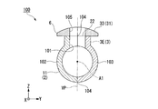
図4に示すように、本実施形態の管楽器100は、第一実施形態の管楽器1と同様の管体2、音孔管3及び指押さえ板6を備える。また、本実施形態の管楽器100では、第一実施形態と同様に、管体2及び音孔管3が一体に形成されている。ただし、本実施形態の管楽器100では、指押さえ板6が、管体2及び音孔管3と別個に形成されている。以下、本実施形態の管楽器100について、具体的に説明する。
本実施形態において、管体2の主管11は、管楽器100の音孔を構成する第一貫通孔101を有する。第一貫通孔101は、主管11の内側から外側に貫通している。
音孔管3は、主管11の外周に一体に形成されている。音孔管3は、主管11の第一貫通孔101と共に管楽器100の音孔を構成している。
音孔管3は、主管11の外周に一体に形成されている。音孔管3は、主管11の第一貫通孔101と共に管楽器100の音孔を構成している。
主管11及び音孔管3を含む構成体は、管楽器100の音孔を分断するように分割された一対の分割構成体102,103によって構成されている。一対の分割構成体102,103の境界104は、主管11の軸線A1及び音孔の軸線と共に同一の仮想面VPに含まれている。本実施形態の管楽器100では、第一実施形態と同様に、主管11が管体2の幅方向(Y軸方向)に蛇行しない。このため、上記の仮想面VPは、管体2の幅方向に直交する平面である。
本実施形態において、一対の分割構成体102,103の境界104は、主管11の幅方向の中央に位置している。このため、一対の分割構成体102,103は、主管11の幅方向の中央を基準として左右対称の形状に形成されている。
本実施形態において、一対の分割構成体102,103の境界104は、主管11の幅方向の中央に位置している。このため、一対の分割構成体102,103は、主管11の幅方向の中央を基準として左右対称の形状に形成されている。
図示しないが、本実施形態の管体2は、第一実施形態と同様に、主管11に対して管体2の高さ方向(Z軸方向)や長手方向(X軸方向)に延び、管体2の幅方向に延びない副管12(図1,2参照)を有する。このため、本実施形態の管楽器100では、例えば主管11、音孔管3及び副管12を含む構成体が、一対の分割構成体102,103によって構成されてもよい。
指押さえ板6は、その板厚方向に貫通する第二貫通孔105を有する。第二貫通孔105は、主管11の第一貫通孔101、音孔管3と共に、管楽器100の音孔を構成している。指押さえ板6は、一対の分割構成体102,103の境界104を覆うように主管11の外周上に配されている。
本実施形態の指押さえ板6は、音孔管3の外側開口端22に現れる一対の分割構成体102,103の境界104を覆うように、音孔管3の外側開口端22に配されている。このように配された指押さえ板6は、第一実施形態と同様に、音孔管3の径方向において音孔管3の外側開口端22よりも外側に延出している。
本実施形態の指押さえ板6は、音孔管3の外側開口端22に現れる一対の分割構成体102,103の境界104を覆うように、音孔管3の外側開口端22に配されている。このように配された指押さえ板6は、第一実施形態と同様に、音孔管3の径方向において音孔管3の外側開口端22よりも外側に延出している。
本実施形態の管楽器100によれば、第一実施形態と同様の効果を奏する。
また、本実施形態の管楽器100では、管体2及び音孔管3を含む構成体が一対の分割構成体102,103によって構成されている。このため、一対の分割構成体102,103を個別に成形でき、管楽器100を容易に製造することが可能となる。
また、本実施形態の管楽器100では、管体2及び音孔管3を含む構成体が一対の分割構成体102,103によって構成されている。このため、一対の分割構成体102,103を個別に成形でき、管楽器100を容易に製造することが可能となる。
また、管体2及び音孔管3を含む構成体は、管楽器100の音孔を分断するように一対の分割構成体102,103に分割されている。このため、一対の分割構成体102,103をつなぎ合わせる前に、音孔の内面を容易に加工することができる。例えば、主管11の内側に位置する音孔の端部に、主管11の内側に向かうにしたがって音孔の内径が徐々に大きくなるアンダーカット構造を容易に形成することができる。アンダーカット構造の形成は、音程など管楽器100の音響的な性能向上に役立つ。すなわち、本実施形態の管楽器100によれば、管楽器100の音響的な性能を容易に確保することもできる。
また、本実施形態の管楽器100では、一対の分割構成体102,103の境界104が指押さえ板6によって覆われている。このため、演奏者が管楽器100を演奏する際、音孔を開閉する演奏者の手指は、指押さえ板6の手指用開口面33に触れるだけであり、一対の分割構成体102,103の境界104に触れることはない。その結果、演奏者は管楽器100を円滑に演奏することができる。以下、この点について具体的に説明する。
一対の分割構成体102,103の境界104には、微小な段差が現れることがある。このため、一対の分割構成体102,103の間の段差に演奏者の手指が触れると、演奏者は違和感やストレスを感じてしまう。これに対し、本実施形態の管楽器100では、一対の分割構成体102,103の境界104が指押さえ板6によって覆われているため、演奏者は違和感やストレスを感じることなく、管楽器100を円滑に演奏することができる。
第二実施形態においては、例えば図5に示すように、管楽器が、音孔管3を備えず、管体2及び指押さえ板6のみ備えてもよい。この場合、指押さえ板6は、主管11の外周に直接配される。このような構成であっても、前述した第二実施形態と同様の効果を奏する。
以上、本発明について詳細に説明したが、本発明は上記実施形態に限定されるものではなく、本発明の趣旨を逸脱しない範囲において種々の変更を加えることが可能である。
本発明の管楽器は、鍵機構8を含むものに限らず、例えば図6,7に示すように、全ての音孔管3を手指で直接開閉するタイプの管楽器に適用可能である。
上記実施形態において、音孔管3は、例えば音孔管3の軸線が主管11の径方向に対して傾斜する方向に真っ直ぐに延びる斜行管部を有してもよい。この場合、音孔管3の軸線は、複数の音孔管3の外側開口端22がこれらを塞ぐ手指に対応した位置となるように、主管11の径方向に対して傾斜する方向に延びるとよい。また、音孔管3は、例えば斜行管部及び上記実施形態と同様の湾曲管部23の両方を有してもよい。
また、主管11や音孔管3は、例えば図6,7に示すように、曲がっていたり、傾斜していたりしなくてもよい。
また、主管11や音孔管3は、例えば図6,7に示すように、曲がっていたり、傾斜していたりしなくてもよい。
複数の音孔管3は、主管11の長手方向に一列に並べられることに限らず、例えば図7に示すように、主管11の周方向に互いにずれて位置してもよい。すなわち、複数の音孔管3の内側開口端21は、例えば主管11の周方向において互いに異なる位置に配されてもよい。
複数の音孔管3の外側開口端22は、例えば図6に示すように、主管11の高さ方向において互いに異なる位置に配されてもよい。また、複数の音孔管3の外側開口端22の向きは、互いに異なっていてもよい。
複数の音孔管3の外側開口端22は、例えば図6に示すように、主管11の高さ方向において互いに異なる位置に配されてもよい。また、複数の音孔管3の外側開口端22の向きは、互いに異なっていてもよい。
指押さえ板6の手指用開口面33は、例えば音孔管3の外側開口端22から離れるにしたがって上方に傾斜するような曲面に形成されてもよい。この場合には、曲面に形成された手指用開口面33によって音孔管3の外側開口端22上に手指を入り込ませる窪み形状が形成されるため、上記実施形態と同様に、演奏者の手指で音孔管3の外側開口端22を正しくかつ簡単に塞ぐことができる。
また、指押さえ板6の手指用開口面33(開口面31)は、例えば図6,7に示すように、平坦面であってもよい。
また、指押さえ板6の手指用開口面33(開口面31)は、例えば図6,7に示すように、平坦面であってもよい。
また、本発明の管楽器は、例えば図6,7に示すように、複数の指押さえ板6を備えてもよい。図6,7に例示する管楽器の主管11の外周には、二つの指押さえ板6(6A,6B)が配されている。図6,7に例示する構成では、第一指押さえ板6Aが主管11の第一端部13側から数えて1番目~5番目の音孔管3J~3Nに対して設けられ、第二指押さえ板6Bが6番目、7番目の音孔管3O、3Pに対して設けられているが、各指押さえ板6に対応する音孔管3の数は任意であってよい。例えば、第一指押さえ板6Aが左手の手指で開閉される音孔管3に対して設けられ、第二指押さえ板6Bが右手の手指で開閉される音孔管3に対して設けられてもよい。このような構成では、図6に例示するように、音孔管3の軸方向長さが異なる場合であっても、各指押さえ板6を単純な形状(図6では平板状)に形成することができる。
また、指押さえ板6は、例えば複数の音孔管3に対して個別に設けられてもよい。この場合、音孔管3の外側開口端22の周囲にある指押さえ板6の開口面31の大きさは、任意であってよいが、例えば演奏者の手指を開口面31に置いても手指が指押さえ板6の延出方向先端の縁部に触れない程度に設定されるとよい。
管楽器が複数の指押さえ板6を備える場合、例えば図7に示すように、主管11は互いに回転可能に連結される二つ以上の管体部16を備え、音孔管3及び指押さえ板6が各管体部16に配されてもよい。
この構成では、二つの管体部16を相互に回転させることで、二つの管体部16に配された音孔管3の外側開口端22の位置(向き)を、主管11の周方向に相対的に変化させることができる。これにより、演奏者の手指の大きさや長さ等に応じて複数の音孔管3の外側開口端22の位置を適切に調整することができる。
この構成では、二つの管体部16を相互に回転させることで、二つの管体部16に配された音孔管3の外側開口端22の位置(向き)を、主管11の周方向に相対的に変化させることができる。これにより、演奏者の手指の大きさや長さ等に応じて複数の音孔管3の外側開口端22の位置を適切に調整することができる。
親指用音孔14は、例えば図6,7に示すように、音程用音孔と同様に主管11の外周から延びる音孔管30によって構成されてもよい。また、親指用音孔14を構成する音孔管30には、上記実施形態と同様に、音孔管30の径方向において音孔管30の外側開口端から音孔管30の外側に延出する指押さえ板60が設けられてもよい。
管楽器の管体2は、任意に構成されてもよい。すなわち、管体2は、例えば副管12を備えず、主管11のみによって構成されてもよい。この場合、管体2(主管11)は、円筒状に限らず、例えば円錐管状に形成されてもよい。
図6に例示する管楽器の管体2(主管11)は、マウスピース4側からベル5側に向かうにしたがって内径寸法が小さくなる円錐管状に形成されている。
図6に例示する管楽器の管体2(主管11)は、マウスピース4側からベル5側に向かうにしたがって内径寸法が小さくなる円錐管状に形成されている。
1,100…管楽器、2…管体、3,3A,3B,3C,3D,3E,3F,3G,3H,3I,3J,3K,3L,3M,3N,3O,3P,30…音孔管、4…マウスピース、5…ベル、6,6A,6B,60…指押さえ板、8…鍵機構、11…主管、12…副管、16,16A,16B…管体部、21…内側開口端、22…外側開口端、31…開口面、101…第一貫通孔、102,103…分割構成体、104…境界、105…第二貫通孔
Claims (5)
- 管体と、
前記管体の外周から延びて形成され、前記管体の内側に開口する内側開口端、及び、前記管体の外側に開口する外側開口端を有する音孔管と、
前記音孔管の径方向において前記音孔管の外側開口端から前記音孔管の外側に延出している指押さえ板と、を備える管楽器。 - 複数の前記音孔管に対して、共通の前記指押さえ板が設けられている請求項1に記載の管楽器。
- 前記指押さえ板のうち前記外側開口端が開口する側の面が曲面に形成されている請求項1又は請求項2に記載の管楽器。
- 前記管体が、互いに回転可能に連結される二つ以上の管体部を備え、
各管体部に、前記音孔管及び前記指押さえ板が配されている請求項1から請求項3のいずれか一項に記載の管楽器。 - 音孔を構成する第一貫通孔を有する管体と、
前記管体の外周上に配され、前記第一貫通孔と共に音孔を構成する第二貫通孔を有する指押さえ板と、を備え、
前記管体が、前記音孔を分断するように分割された一対の分割構成体によって構成され、
前記指押さえ板が、前記一対の分割構成体の境界を覆うように前記管体の外周上に配されている管楽器。
Priority Applications (5)
| Application Number | Priority Date | Filing Date | Title |
|---|---|---|---|
| EP16851138.4A EP3358563B1 (en) | 2015-09-30 | 2016-09-13 | Wind instrument |
| US15/753,641 US10354624B2 (en) | 2015-09-30 | 2016-09-13 | Wind instrument |
| CN201680056728.3A CN108140367B (zh) | 2015-09-30 | 2016-09-13 | 管乐器 |
| EP21201246.2A EP3971884B1 (en) | 2015-09-30 | 2016-09-13 | Wind instrument |
| JP2017543092A JP6519660B2 (ja) | 2015-09-30 | 2016-09-13 | 管楽器 |
Applications Claiming Priority (2)
| Application Number | Priority Date | Filing Date | Title |
|---|---|---|---|
| JP2015192842 | 2015-09-30 | ||
| JP2015-192842 | 2015-09-30 |
Publications (1)
| Publication Number | Publication Date |
|---|---|
| WO2017056964A1 true WO2017056964A1 (ja) | 2017-04-06 |
Family
ID=58423577
Family Applications (1)
| Application Number | Title | Priority Date | Filing Date |
|---|---|---|---|
| PCT/JP2016/076954 Ceased WO2017056964A1 (ja) | 2015-09-30 | 2016-09-13 | 管楽器 |
Country Status (5)
| Country | Link |
|---|---|
| US (1) | US10354624B2 (ja) |
| EP (2) | EP3358563B1 (ja) |
| JP (1) | JP6519660B2 (ja) |
| CN (1) | CN108140367B (ja) |
| WO (1) | WO2017056964A1 (ja) |
Cited By (2)
| Publication number | Priority date | Publication date | Assignee | Title |
|---|---|---|---|---|
| USD929494S1 (en) * | 2019-06-07 | 2021-08-31 | Yamaha Corporation | Wind instrument |
| USD929495S1 (en) * | 2019-06-07 | 2021-08-31 | Yamaha Corporation | Wind instrument |
Families Citing this family (2)
| Publication number | Priority date | Publication date | Assignee | Title |
|---|---|---|---|---|
| WO2017056964A1 (ja) * | 2015-09-30 | 2017-04-06 | ヤマハ株式会社 | 管楽器 |
| EP3428910B1 (en) * | 2016-03-07 | 2023-04-12 | Yamaha Corporation | Wind instrument |
Citations (8)
| Publication number | Priority date | Publication date | Assignee | Title |
|---|---|---|---|---|
| US3866507A (en) * | 1973-07-26 | 1975-02-18 | Raoul J Eajardo | Noncircular head joint for a concert flute and method of manufacture |
| JPS50137025U (ja) * | 1974-04-26 | 1975-11-12 | ||
| JPS5255233U (ja) * | 1975-10-20 | 1977-04-21 | ||
| JPS5533178A (en) * | 1978-08-31 | 1980-03-08 | Takamura Toyama | Acoustic hole device for plastic flute |
| JPH02107198U (ja) * | 1989-02-15 | 1990-08-27 | ||
| JPH0583796U (ja) * | 1992-04-10 | 1993-11-12 | 一己 遠藤 | リコーダー |
| JP2013213952A (ja) * | 2012-04-02 | 2013-10-17 | Kaori Isoguchi | 管楽器、音孔の形成方法、音孔形成用パッド |
| JP2015043068A (ja) * | 2013-07-22 | 2015-03-05 | 道夫 高嶋 | リコーダー及びそれに用いるリング状部材 |
Family Cites Families (38)
| Publication number | Priority date | Publication date | Assignee | Title |
|---|---|---|---|---|
| US968694A (en) * | 1908-03-14 | 1910-08-30 | C G Conn Co | Tubing for wind instruments. |
| US1455440A (en) * | 1922-02-16 | 1923-05-15 | Hofinger Florent | Process of manufacturing flutes |
| US1761329A (en) * | 1928-05-07 | 1930-06-03 | Frank Holton & Company | Wind musical instrument |
| US1809380A (en) * | 1928-10-12 | 1931-06-09 | Conn Ltd C G | Clarinet and the method of manufacture thereof |
| US1801690A (en) * | 1930-02-06 | 1931-04-21 | Pruefer Gustav | Musical instrument |
| US3062084A (en) | 1960-03-24 | 1962-11-06 | Thomas S Ogilvie | Bass flute |
| US3487742A (en) * | 1968-03-01 | 1970-01-06 | Warren L Mills | Inner tone for a musical instrument |
| GB1182919A (en) * | 1969-01-22 | 1970-03-04 | George Raw Robinson | An Improvement in Wind Instruments of the Flute Family. |
| US3805665A (en) * | 1971-06-21 | 1974-04-23 | Nippon Musical Instruments Mfg | Wind type musical instrument |
| US3722348A (en) * | 1972-05-01 | 1973-03-27 | H Visser | Wind instrument |
| JPS6013199B2 (ja) * | 1978-03-01 | 1985-04-05 | 信男 外山 | 管楽器 |
| EP0205480A1 (de) * | 1984-12-04 | 1986-12-30 | Wretschitsch, Walter | Blasinstrument |
| FI872561L (fi) * | 1987-06-08 | 1989-03-07 | Matti Kaehoenen | Ett blaosinstruments stomkonstruktion samt foerfarande foer framstaellning av ifraogavarande blaosinstrumentets stomkonstruktion. |
| US5309806A (en) * | 1991-10-28 | 1994-05-10 | Stavash John C | Woodwind musical instrument |
| CN1096606A (zh) * | 1993-06-14 | 1994-12-21 | 蔡敬民 | 加键平均律竹笛 |
| USD360904S (en) * | 1994-01-10 | 1995-08-01 | Schilling Samuel D | Toy musical instrument |
| JP3116845B2 (ja) * | 1996-12-06 | 2000-12-11 | ヤマハ株式会社 | ファゴット |
| US6852917B2 (en) * | 2001-10-16 | 2005-02-08 | Mcaleenan Michael | Construction and method of wind musical instrument |
| US20040111865A1 (en) * | 2002-12-13 | 2004-06-17 | Jay Craig | Method and apparatus of forming a bagpipe chanter |
| US7459621B2 (en) * | 2006-08-02 | 2008-12-02 | Straubinger David J | Pad assembly for woodwinds, particularly flutes |
| CN201035955Y (zh) | 2007-05-28 | 2008-03-12 | 李青山 | 一种低音箫笛 |
| ATE525718T1 (de) * | 2008-06-27 | 2011-10-15 | Ernst Reisner | Griffmechanik für holzblasinstrumente |
| US9208758B2 (en) * | 2008-12-12 | 2015-12-08 | University Of Washington | Unified octave/register key and vent for musical wind instruments |
| CN201518217U (zh) | 2009-10-14 | 2010-06-30 | 黄朝庆 | 弯管洞箫 |
| JP2011186443A (ja) | 2010-02-12 | 2011-09-22 | Yamaha Corp | 管楽器の管体 |
| EP2360674A2 (en) * | 2010-02-12 | 2011-08-24 | Yamaha Corporation | Pipe structure of wind instrument |
| DE102011010124B4 (de) * | 2010-07-17 | 2014-09-25 | Anton Braun | Konische C-Fuß Piccoloflöte mit einem Daumenloch |
| US20130145920A1 (en) | 2010-08-20 | 2013-06-13 | Backs Verse Co., Ltd. | Water leakage prevention tool, saxophone, and wind instrument |
| US8273975B2 (en) | 2010-08-30 | 2012-09-25 | Barbara Gisler | Flute |
| JP4995956B2 (ja) | 2010-09-15 | 2012-08-08 | トマジ ヴェルナー | フルート |
| JP2014016407A (ja) | 2012-07-06 | 2014-01-30 | Lyrist:Kk | オカリナ、及びその製造方法 |
| CN203013225U (zh) * | 2012-11-09 | 2013-06-19 | 李复斌 | 一种加键笛子 |
| JP2015192842A (ja) | 2014-03-28 | 2015-11-05 | 株式会社ケアコム | ナースコールシステム |
| CN204029343U (zh) * | 2014-06-26 | 2014-12-17 | 杨抓钢 | 一种便携带式笛子 |
| HK1204430A2 (en) * | 2014-09-25 | 2015-11-13 | Nuvo Instrumental (Asia) Limited | A key member for a musical instrument |
| WO2016129063A1 (ja) * | 2015-02-10 | 2016-08-18 | 株式会社オフィス樹エージェンシー | オカリナ専用息圧調整弱音装置およびオカリナへの取り付け用二段階式アダプター |
| JP6679866B2 (ja) * | 2015-09-30 | 2020-04-15 | ヤマハ株式会社 | 管楽器 |
| WO2017056964A1 (ja) * | 2015-09-30 | 2017-04-06 | ヤマハ株式会社 | 管楽器 |
-
2016
- 2016-09-13 WO PCT/JP2016/076954 patent/WO2017056964A1/ja not_active Ceased
- 2016-09-13 EP EP16851138.4A patent/EP3358563B1/en not_active Not-in-force
- 2016-09-13 JP JP2017543092A patent/JP6519660B2/ja active Active
- 2016-09-13 EP EP21201246.2A patent/EP3971884B1/en active Active
- 2016-09-13 CN CN201680056728.3A patent/CN108140367B/zh active Active
- 2016-09-13 US US15/753,641 patent/US10354624B2/en active Active
Patent Citations (8)
| Publication number | Priority date | Publication date | Assignee | Title |
|---|---|---|---|---|
| US3866507A (en) * | 1973-07-26 | 1975-02-18 | Raoul J Eajardo | Noncircular head joint for a concert flute and method of manufacture |
| JPS50137025U (ja) * | 1974-04-26 | 1975-11-12 | ||
| JPS5255233U (ja) * | 1975-10-20 | 1977-04-21 | ||
| JPS5533178A (en) * | 1978-08-31 | 1980-03-08 | Takamura Toyama | Acoustic hole device for plastic flute |
| JPH02107198U (ja) * | 1989-02-15 | 1990-08-27 | ||
| JPH0583796U (ja) * | 1992-04-10 | 1993-11-12 | 一己 遠藤 | リコーダー |
| JP2013213952A (ja) * | 2012-04-02 | 2013-10-17 | Kaori Isoguchi | 管楽器、音孔の形成方法、音孔形成用パッド |
| JP2015043068A (ja) * | 2013-07-22 | 2015-03-05 | 道夫 高嶋 | リコーダー及びそれに用いるリング状部材 |
Non-Patent Citations (1)
| Title |
|---|
| See also references of EP3358563A4 * |
Cited By (2)
| Publication number | Priority date | Publication date | Assignee | Title |
|---|---|---|---|---|
| USD929494S1 (en) * | 2019-06-07 | 2021-08-31 | Yamaha Corporation | Wind instrument |
| USD929495S1 (en) * | 2019-06-07 | 2021-08-31 | Yamaha Corporation | Wind instrument |
Also Published As
| Publication number | Publication date |
|---|---|
| CN108140367B (zh) | 2021-12-28 |
| EP3971884A1 (en) | 2022-03-23 |
| JP6519660B2 (ja) | 2019-05-29 |
| EP3358563B1 (en) | 2021-12-15 |
| JPWO2017056964A1 (ja) | 2018-02-01 |
| EP3358563A4 (en) | 2019-06-05 |
| EP3358563A1 (en) | 2018-08-08 |
| EP3971884B1 (en) | 2023-06-07 |
| CN108140367A (zh) | 2018-06-08 |
| US10354624B2 (en) | 2019-07-16 |
| US20180190245A1 (en) | 2018-07-05 |
Similar Documents
| Publication | Publication Date | Title |
|---|---|---|
| JP6679866B2 (ja) | 管楽器 | |
| JPWO2017056964A1 (ja) | 管楽器 | |
| JP5572818B2 (ja) | 楽器 | |
| US8395038B2 (en) | Pick for an instrument | |
| JP4886893B1 (ja) | 管楽器 | |
| JP6602900B2 (ja) | 演奏補助具 | |
| JP5949679B2 (ja) | 管楽器用消音器 | |
| CN101004907A (zh) | 七孔笛 | |
| JP6766387B2 (ja) | 管楽器 | |
| CN223022882U (zh) | 具有低音扩充组件的新笛 | |
| US20070245879A1 (en) | Height adjustable key assembly for a saxophone | |
| JP6022150B2 (ja) | 弦楽器演奏用の指カバー | |
| JP3188272U (ja) | 管楽器のアダプター | |
| JP6657793B2 (ja) | 管楽器 | |
| TWI753638B (zh) | 銅管樂器 | |
| KR102081000B1 (ko) | 소리발생부에 가이드 돌부를 갖는 오카리나 | |
| TWM663242U (zh) | 具有低音擴充組件之新笛 | |
| JP2025101843A (ja) | 釣竿 | |
| JP2017086861A (ja) | ラケット | |
| KR20100020683A (ko) | 클라리넷 | |
| JP4259735B2 (ja) | クラリネットのバレル | |
| TWM509959U (zh) | 薩克斯風彎脖之結構 | |
| TWM472289U (zh) | 帶磁樂器 | |
| Paley | Thinking like a Pianist/Mathematician/Potter-Designer: Strategies for Tuning Ocarinas | |
| TWM526161U (zh) | 口笛 |
Legal Events
| Date | Code | Title | Description |
|---|---|---|---|
| 121 | Ep: the epo has been informed by wipo that ep was designated in this application |
Ref document number: 16851138 Country of ref document: EP Kind code of ref document: A1 |
|
| ENP | Entry into the national phase |
Ref document number: 2017543092 Country of ref document: JP Kind code of ref document: A |
|
| NENP | Non-entry into the national phase |
Ref country code: DE |