WO2017061146A1 - 繊維強化複合部材の成形装置 - Google Patents
繊維強化複合部材の成形装置 Download PDFInfo
- Publication number
- WO2017061146A1 WO2017061146A1 PCT/JP2016/068689 JP2016068689W WO2017061146A1 WO 2017061146 A1 WO2017061146 A1 WO 2017061146A1 JP 2016068689 W JP2016068689 W JP 2016068689W WO 2017061146 A1 WO2017061146 A1 WO 2017061146A1
- Authority
- WO
- WIPO (PCT)
- Prior art keywords
- heat removal
- removal prevention
- molding
- cavity
- molding die
- Prior art date
- Legal status (The legal status is an assumption and is not a legal conclusion. Google has not performed a legal analysis and makes no representation as to the accuracy of the status listed.)
- Ceased
Links
Images


Classifications
-
- B—PERFORMING OPERATIONS; TRANSPORTING
- B29—WORKING OF PLASTICS; WORKING OF SUBSTANCES IN A PLASTIC STATE IN GENERAL
- B29C—SHAPING OR JOINING OF PLASTICS; SHAPING OF MATERIAL IN A PLASTIC STATE, NOT OTHERWISE PROVIDED FOR; AFTER-TREATMENT OF THE SHAPED PRODUCTS, e.g. REPAIRING
- B29C70/00—Shaping composites, i.e. plastics material comprising reinforcements, fillers or preformed parts, e.g. inserts
- B29C70/04—Shaping composites, i.e. plastics material comprising reinforcements, fillers or preformed parts, e.g. inserts comprising reinforcements only, e.g. self-reinforcing plastics
- B29C70/28—Shaping operations therefor
- B29C70/40—Shaping or impregnating by compression not applied
- B29C70/42—Shaping or impregnating by compression not applied for producing articles of definite length, i.e. discrete articles
- B29C70/46—Shaping or impregnating by compression not applied for producing articles of definite length, i.e. discrete articles using matched moulds, e.g. for deforming sheet moulding compounds [SMC] or prepregs
-
- B—PERFORMING OPERATIONS; TRANSPORTING
- B29—WORKING OF PLASTICS; WORKING OF SUBSTANCES IN A PLASTIC STATE IN GENERAL
- B29C—SHAPING OR JOINING OF PLASTICS; SHAPING OF MATERIAL IN A PLASTIC STATE, NOT OTHERWISE PROVIDED FOR; AFTER-TREATMENT OF THE SHAPED PRODUCTS, e.g. REPAIRING
- B29C33/00—Moulds or cores; Details thereof or accessories therefor
- B29C33/02—Moulds or cores; Details thereof or accessories therefor with incorporated heating or cooling means
-
- B—PERFORMING OPERATIONS; TRANSPORTING
- B29—WORKING OF PLASTICS; WORKING OF SUBSTANCES IN A PLASTIC STATE IN GENERAL
- B29C—SHAPING OR JOINING OF PLASTICS; SHAPING OF MATERIAL IN A PLASTIC STATE, NOT OTHERWISE PROVIDED FOR; AFTER-TREATMENT OF THE SHAPED PRODUCTS, e.g. REPAIRING
- B29C43/00—Compression moulding, i.e. applying external pressure to flow the moulding material; Apparatus therefor
- B29C43/32—Component parts, details or accessories; Auxiliary operations
- B29C43/34—Feeding the material to the mould or the compression means
-
- B—PERFORMING OPERATIONS; TRANSPORTING
- B29—WORKING OF PLASTICS; WORKING OF SUBSTANCES IN A PLASTIC STATE IN GENERAL
- B29C—SHAPING OR JOINING OF PLASTICS; SHAPING OF MATERIAL IN A PLASTIC STATE, NOT OTHERWISE PROVIDED FOR; AFTER-TREATMENT OF THE SHAPED PRODUCTS, e.g. REPAIRING
- B29C43/00—Compression moulding, i.e. applying external pressure to flow the moulding material; Apparatus therefor
- B29C43/32—Component parts, details or accessories; Auxiliary operations
- B29C43/36—Moulds for making articles of definite length, i.e. discrete articles
- B29C43/361—Moulds for making articles of definite length, i.e. discrete articles with pressing members independently movable of the parts for opening or closing the mould, e.g. movable pistons
-
- B—PERFORMING OPERATIONS; TRANSPORTING
- B29—WORKING OF PLASTICS; WORKING OF SUBSTANCES IN A PLASTIC STATE IN GENERAL
- B29C—SHAPING OR JOINING OF PLASTICS; SHAPING OF MATERIAL IN A PLASTIC STATE, NOT OTHERWISE PROVIDED FOR; AFTER-TREATMENT OF THE SHAPED PRODUCTS, e.g. REPAIRING
- B29C43/00—Compression moulding, i.e. applying external pressure to flow the moulding material; Apparatus therefor
- B29C43/32—Component parts, details or accessories; Auxiliary operations
- B29C43/52—Heating or cooling
-
- B—PERFORMING OPERATIONS; TRANSPORTING
- B29—WORKING OF PLASTICS; WORKING OF SUBSTANCES IN A PLASTIC STATE IN GENERAL
- B29C—SHAPING OR JOINING OF PLASTICS; SHAPING OF MATERIAL IN A PLASTIC STATE, NOT OTHERWISE PROVIDED FOR; AFTER-TREATMENT OF THE SHAPED PRODUCTS, e.g. REPAIRING
- B29C70/00—Shaping composites, i.e. plastics material comprising reinforcements, fillers or preformed parts, e.g. inserts
- B29C70/04—Shaping composites, i.e. plastics material comprising reinforcements, fillers or preformed parts, e.g. inserts comprising reinforcements only, e.g. self-reinforcing plastics
- B29C70/28—Shaping operations therefor
- B29C70/54—Component parts, details or accessories; Auxiliary operations, e.g. feeding or storage of prepregs or SMC after impregnation or during ageing
- B29C70/546—Measures for feeding or distributing the matrix material in the reinforcing structure
-
- B—PERFORMING OPERATIONS; TRANSPORTING
- B32—LAYERED PRODUCTS
- B32B—LAYERED PRODUCTS, i.e. PRODUCTS BUILT-UP OF STRATA OF FLAT OR NON-FLAT, e.g. CELLULAR OR HONEYCOMB, FORM
- B32B5/00—Layered products characterised by the non- homogeneity or physical structure, i.e. comprising a fibrous, filamentary, particulate or foam layer; Layered products characterised by having a layer differing constitutionally or physically in different parts
- B32B5/22—Layered products characterised by the non- homogeneity or physical structure, i.e. comprising a fibrous, filamentary, particulate or foam layer; Layered products characterised by having a layer differing constitutionally or physically in different parts characterised by the presence of two or more layers which are next to each other and are fibrous, filamentary, formed of particles or foamed
- B32B5/24—Layered products characterised by the non- homogeneity or physical structure, i.e. comprising a fibrous, filamentary, particulate or foam layer; Layered products characterised by having a layer differing constitutionally or physically in different parts characterised by the presence of two or more layers which are next to each other and are fibrous, filamentary, formed of particles or foamed one layer being a fibrous or filamentary layer
- B32B5/26—Layered products characterised by the non- homogeneity or physical structure, i.e. comprising a fibrous, filamentary, particulate or foam layer; Layered products characterised by having a layer differing constitutionally or physically in different parts characterised by the presence of two or more layers which are next to each other and are fibrous, filamentary, formed of particles or foamed one layer being a fibrous or filamentary layer another layer next to it also being fibrous or filamentary
-
- B—PERFORMING OPERATIONS; TRANSPORTING
- B29—WORKING OF PLASTICS; WORKING OF SUBSTANCES IN A PLASTIC STATE IN GENERAL
- B29C—SHAPING OR JOINING OF PLASTICS; SHAPING OF MATERIAL IN A PLASTIC STATE, NOT OTHERWISE PROVIDED FOR; AFTER-TREATMENT OF THE SHAPED PRODUCTS, e.g. REPAIRING
- B29C43/00—Compression moulding, i.e. applying external pressure to flow the moulding material; Apparatus therefor
- B29C43/32—Component parts, details or accessories; Auxiliary operations
- B29C43/36—Moulds for making articles of definite length, i.e. discrete articles
- B29C43/361—Moulds for making articles of definite length, i.e. discrete articles with pressing members independently movable of the parts for opening or closing the mould, e.g. movable pistons
- B29C2043/3613—Moulds for making articles of definite length, i.e. discrete articles with pressing members independently movable of the parts for opening or closing the mould, e.g. movable pistons applying pressure locally
-
- B—PERFORMING OPERATIONS; TRANSPORTING
- B32—LAYERED PRODUCTS
- B32B—LAYERED PRODUCTS, i.e. PRODUCTS BUILT-UP OF STRATA OF FLAT OR NON-FLAT, e.g. CELLULAR OR HONEYCOMB, FORM
- B32B2250/00—Layers arrangement
- B32B2250/20—All layers being fibrous or filamentary
Definitions
- the present disclosure relates to a fiber reinforced composite member forming apparatus used for forming a fiber reinforced composite member formed by laminating a plurality of prepregs in which a fiber woven fabric is impregnated with a thermosetting resin or a thermoplastic resin as a matrix. Is.
- thermoplastic CFRP member fiber reinforced composite member
- a thermoplastic CFRP member fiber reinforced composite member
- the molding apparatus includes a lower mold (one molding mold) and an upper mold (the other molding mold) that approaches and separates from the lower mold, and the upper mold projects downward.
- the lower mold is provided with a cavity that opens upward.
- thermoplastic CFRP members In this molding apparatus, at the time of molding, a plurality of stacked prepregs are set on the lower mold cavity in the mold open state, and then the upper mold is lowered to place the prepreg between the upper mold core and the lower mold cavity.
- the prepreg in which the thermoplastic resin is melted is pressed between the upper mold and the lower mold while being sandwiched and heated. Then, after this pressurization, the thermoplastic resin is cooled and solidified through the upper mold and the lower mold to obtain various shapes of thermoplastic CFRP members.
- thermoplastic CFRP member has a problem that defects such as wrinkles due to meandering of carbon fibers may occur, and it has been a conventional problem to solve this problem.
- the present disclosure has been made by paying attention to the above-described conventional problems, and can prevent heat from escaping from around the cavity of at least one molding die during heating during molding, and as a result, It aims at providing the shaping
- the present invention provides one molding die having a cavity in contact with a prepreg in which a fiber woven fabric is impregnated with a resin (thermosetting resin or thermoplastic resin), and the cavity of the one molding die in a clamped state.
- a heating part that heats the resin of the prepreg through the other molding die and the other molding die sandwiching the prepreg laminated between a plurality of sheets.
- One molding die is provided with a cavity heat removal prevention portion that prevents heat from escaping around the cavity when the resin of the prepreg is heated. It is.
- the apparatus for molding a fiber-reinforced composite member according to the present invention it is possible to prevent heat from escaping from the periphery of the cavity of at least one molding die during heating during molding. Therefore, variations in heating temperature are less likely to occur, and a very excellent effect is obtained that it is possible to obtain a fiber-reinforced composite member that has almost no defects such as wrinkles.
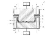
- FIG. 2 is an explanatory cross-sectional view showing a molding apparatus for fiber-reinforced composite members in FIG. 1. It is sectional explanatory drawing which shows the shaping
- FIG. 1 and 2 show an embodiment of a fiber reinforced composite member molding apparatus according to the present invention.
- this forming apparatus 1 forms a fiber-reinforced composite member (for example, a thermoplastic CFRP member) formed by laminating a plurality of prepregs in which a fiber woven fabric is impregnated with a thermosetting resin or a thermoplastic resin.
- the apparatus 1 includes a lower die (one molding die) 2 and an upper die (the other molding die) 3.
- the fiber reinforced composite member is formed into a flat plate shape by alternately laminating a plurality of prepregs each having a different fiber orientation direction in which a fiber woven fabric is impregnated with a thermosetting resin or a thermoplastic resin.
- the lower mold 2 has a cavity 21 as shown in FIG.
- the upper die 3 that descends and rises and approaches and separates from the lower die 2 is fitted with the cavity 21 of the lower die 2 in a clamped state, and a prepreg laminate (a plurality of prepregs laminated between the cavities 21). It has a core 31 that sandwiches a fiber-reinforced composite member (P) before molding.
- the lower mold 2 includes a heat source 10 as a heating unit that heats the molding surface 21 a that contacts the prepreg laminate P of the cavity 21.
- the upper mold 3 also includes a heat source 10 as a heating unit that heats the molding surface 31 a in contact with the prepreg laminate P of the core 31.
- These heat sources 10 and 10 respectively apply heat to the lower mold 2 and the upper mold 3 from the side opposite to the molding surfaces 21a and 31a.
- the molding apparatus 1 includes a cavity heat removal prevention unit 26 disposed so as to surround the cavity 21 in the lower mold 2.
- the cavity heat removal prevention portion 26 includes a plurality of heat removal prevention cells 23 that are opened around the cavity 21 on the side opposite to the side where the molding surface 21 a is located, and each of these heat removal prevention cells 23.
- the heater 4 arranged in one is provided.
- the cavity heat removal prevention part 26 heats the surroundings of the cavity 21 by heating the heat removal prevention cell 23 with the heater 4 when the thermosetting resin or thermoplastic resin of the prepreg laminate P is heated. It prevents you from escaping.
- the molding apparatus 1 includes a core heat removal prevention portion 36 disposed so as to surround the periphery of the core 31 in the upper mold 3.
- the core heat removal prevention portion 36 includes a plurality of heat removal prevention cells 33 that open on the opposite side of the periphery of the core 31 where the molding surface 31 a is located, and each of the heat removal prevention cells 33.
- the heater 4 arranged in one is provided.
- the core heat removal prevention part 36 also heats the surroundings of the core 31 by heating the inside of the heat removal prevention cell 33 with the heater 4 when the thermosetting resin or the thermoplastic resin of the prepreg laminate P is heated. It prevents you from escaping.
- a prepreg laminate P in which a plurality of prepregs are laminated on the cavity 21 of the lower mold 2 in a state where the mold is opened is set.
- the upper die 3 is lowered and clamped, and the prepreg laminate P is sandwiched between the core 31 of the upper die 3 and the cavity 21 of the lower die 2, and the prepreg is heated by the upper and lower heat sources 10, 10 as heating units. While heat is applied to the laminate P, the prepreg laminate P in which the thermosetting resin or the thermoplastic resin is melted is pressed with the upper mold 3 and the lower mold 2.
- the inside of the heat removal prevention cell 23 of the cavity heat removal prevention part 26 arranged so as to surround the cavity 21 is heated by the heater 4. Heat is prevented from escaping around the cavity 21.
- the inside of the heat removal prevention cell 33 of the core heat removal prevention portion 36 arranged so as to surround the core 31 is heated by the heater 4. Therefore, the heat from the heat source 10 is prevented from escaping around the core 31.
- thermosetting resin after making the heat source 10 perform heating operation continuously and hardening a thermosetting resin, the heating operation of the heat source 10 is stopped, and a prepreg laminated body A molded product (fiber-reinforced composite member) of P is obtained.
- the resin is a thermoplastic resin, after the pressurization, the heating operation of the heat source 10 is stopped, and the thermoplastic resin is cooled and solidified through the upper mold 3 and the lower mold 2. A molded product (fiber reinforced composite member) of the prepreg laminate P is obtained.
- this molding apparatus not only the cavity 21 of the lower mold 2 but also the cavity 21 of the lower mold 2 is fitted when the prepreg laminate P in which a plurality of prepregs are stacked is heated and pressurized. Since heat does not escape from the periphery of the core 31, the prepreg laminate P is heated without variation. As a result, a molded product (fiber reinforced composite member) of the prepreg laminate P free from defects such as wrinkles due to meandering of fibers is obtained.
- the cavity heat removal prevention unit 26 that prevents heat from escaping around the cavity 21 of the lower die 2 and the core that prevents heat from escaping around the core 31 of the upper die 3. Since the configuration in which the heaters 4 are respectively disposed in the heat removal prevention cells 23 and 33 is employed as the heat removal prevention portion 36, the configuration can be simplified.
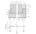
- FIG. 3 shows another embodiment of the apparatus for molding a fiber-reinforced composite member according to the present invention.
- the molding apparatus 1A of this embodiment also includes an upper mold 3A having a lower mold 2A having a cavity 21A and a core 31A that are close to each other with a prepreg laminate P in which a plurality of prepregs are laminated. It has.
- the lower mold 2A includes a plurality of heaters 14 for heating the molding surface 21a in contact with the prepreg laminate P of the cavity 21A for each of a plurality of regions.
- the upper mold 3A also includes a plurality of heaters 14 for heating the molding surface 31a in contact with the prepreg laminate P of the core 31A for each of a plurality of regions.
- a plurality of heating cells 22 that open on the back side of the molding surface 21a are formed in the lower mold 2A corresponding to a plurality of regions, while heating that opens on the back side of the molding surface 31a also in the upper mold 3A.
- a plurality of cells 32 are formed corresponding to a plurality of regions, and the heating heater 14 is arranged in each of the heating cells 22 and 32 to constitute a heating unit. ing.
- the molding apparatus 1A includes a cavity heat removal prevention unit 26A arranged so as to surround the plurality of heating cells 22 in the lower mold 2A.
- the cavity heat removal prevention portion 26A includes a plurality of heat removal prevention cells 23 that are opened around the plurality of heating cells 22 on the side opposite to the side on which the molding surface 21a is located, and these heat removal prevention cells 23.
- a heater having the same configuration as that of the heating heater 14 constituting the heating unit is used, but the present invention is not limited to this.
- the cavity heat removal prevention part 26A is configured to heat the inside of the heat removal prevention cell 23 with the heater 4 when the thermosetting resin or the thermoplastic resin of the prepreg laminate P is heated. It prevents you from escaping.
- the molding apparatus 1A includes a core heat removal prevention portion 36A arranged so as to surround the plurality of heating cells 32 in the upper mold 3A.
- the core heat removal prevention part 36A includes a plurality of heat removal prevention cells 33 that are open around the plurality of heating cells 32 on the side opposite to the side on which the molding surface 31a is located, and these heat removal prevention cells 33.
- a heater having the same configuration as that of the heating heater 14 constituting the heating unit is used, but the present invention is not limited to this.
- This heat removal prevention part 36A for the core also heats around the core 31A by heating the inside of the heat removal prevention cell 33 with the heater 4 when the thermosetting resin or the thermoplastic resin of the prepreg laminate P is heated. It prevents you from escaping.
- a prepreg laminate P in which a plurality of prepregs are laminated is set on the cavity 21A of the lower mold 2A in a state where the mold is opened.
- the upper die 3A is lowered to form a clamping state, and the prepreg laminate P is sandwiched between the core 31A of the upper die 3A and the cavity 21A of the lower die 2A, and the plurality of heaters 14 constituting the heating unit are used. While applying heat to the prepreg laminate P, the prepreg laminate P in which the thermosetting resin or the thermoplastic resin is melted is pressed with the upper mold 3A and the lower mold 2A.
- the inside of the heat removal prevention cell 23 of the cavity heat removal prevention portion 26 arranged so as to surround the plurality of heating cells 22 is a heater different from the heater 14 for heating. 4, the heat from the plurality of heating heaters 14 constituting the heating unit is prevented from escaping around the cavity 21 ⁇ / b> A, while the upper die 3 ⁇ / b> A also surrounds the plurality of heating cells 32. Since the inside of the heat removal prevention cell 33 of the core heat removal prevention part 36 disposed so as to be surrounded is heated by the heater 4 different from the heater 14 for heating, the plurality of heating heaters 14 constituting the heating part are heated. Heat is prevented from escaping around the core 31A.
- the resin when the resin is a thermosetting resin, the plurality of heating heaters 14 constituting the heating unit are caused to continue the heating operation to cure the thermosetting resin.
- a molded product (fiber reinforced composite member) of the prepreg laminate P can be obtained.
- the resin is a thermoplastic resin
- the power supply to the plurality of heaters 14 is stopped, and the thermoplastic resin is cooled through the upper mold 3A and the lower mold 2A.
- solidifying a molded product (fiber reinforced composite member) of the prepreg laminate P is obtained.
- this molding apparatus 1A not only the cavity 21A of the lower mold 2A but also the cavity 21A of the lower mold 2A is fitted at the time of heating and pressurizing the prepreg laminate P in which a plurality of prepregs are laminated. Since heat does not escape from the periphery of the core 31A, heating to the prepreg laminate P is performed without variation. As a result, a molded product (fiber reinforced composite member) of the prepreg laminate P free from defects such as wrinkles due to meandering of fibers is obtained.
- the molding surface 21a of the cavity 21A in the lower mold 2A and the molding surface 31a of the core 31A in the upper mold 3A are each divided into a plurality of regions.
- the lower mold 2A and the upper mold 3A are provided with a plurality of heating cells 22 and 32 that open on the back side of the respective molding surfaces 21a and 31a corresponding to the plurality of regions, and these heating cells are provided. Since the heating heaters 14 are respectively disposed at 22 and 32, the prepreg laminate P is more uniformly heated when the prepreg laminate P is heated and pressurized.
- a plurality of heating cells 22, 32 are provided in the lower mold 2A and the upper mold 3A.
- the temperature Te of the portion corresponding to the end portion of the prepreg laminate P of the molding surfaces 21a and 31a tends to be gradually lower than the temperature Tc of the central portion of the molding surfaces 21a and 31a. is there.
- the heating degree of each heating heater 14 in the heating cells 22 and 32 corresponding to the end of the prepreg laminate P is increased, it corresponds to the end of the prepreg laminate P on the molding surfaces 21a and 31a.
- the temperature of the portion becomes higher (Tf) than the temperature Tc of the central portion, and the temperature distribution on the molding surfaces 21a and 31a is not leveled.
- the heat removal prevention cells around the plurality of heating cells 22 and 32 are provided. 23 and 33, and when the heater 4 is arranged in the heat removal prevention cells 23 and 33 in addition to the heater 14, the molding surfaces 21a, The temperature of the end portion of 31a becomes equal to the temperature Tc of the central portion, and as a result, the prepreg laminate P is heated uniformly.
- the upper molds 3 and 3A have the cores 31 and 31A fitted to the cavities 21 and 21A of the lower molds 2 and 2A in the clamped state is described as an example.
- the upper mold 3, 3A may have a flat shape such that the molding surface side of the upper mold 3, 3A is shallowly accommodated in the cavities 21, 21A of the lower mold 2, 2A.
- the fiber woven fabric constituting the prepreg is a carbon fiber woven fabric using carbon fibers for the fibers
- the present invention is not limited thereto.
- the configuration of the fiber-reinforced composite member forming apparatus according to the present disclosure is not limited to the above-described embodiment.
- one molding die having a cavity in contact with a prepreg in which a fiber woven fabric is impregnated with a resin (thermosetting resin or thermoplastic resin), and the one molding die in a clamped state.
- a heating part for heating the resin of the prepreg via the other molding die and the other molding die sandwiching the prepreg laminated with a plurality of cavities of the mold
- a fiber reinforced composite member for forming the fiber reinforced composite member by pressing the resin of the prepreg laminated between the one molding die and the other molding die while heating by the heating unit.
- the one mold is provided with a cavity heat removal prevention unit that prevents heat from escaping around the cavity when the resin of the prepreg is heated. It is set to Configurations.
- heat does not escape from the periphery of the cavity of one molding die at the time of heating and pressurizing a plurality of prepregs laminated. Heating of the prepregs laminated with each other is performed without variation. Therefore, a fiber-reinforced composite member free from defects such as wrinkles due to fiber meandering can be obtained.
- the other molding die is fitted with the cavity of the one molding die in a clamped state and sandwiches a plurality of the prepregs stacked between the cavities. And the other molding die is provided with a core heat removal prevention portion that prevents heat from escaping around the core when the resin of the prepreg is heated.
- the apparatus for molding a fiber reinforced composite member In the apparatus for molding a fiber reinforced composite member according to the second aspect of the present invention, not only the cavity of one molding die but also the cavity of this one molding die at the time of heating and pressurizing a plurality of prepregs laminated. Since heat does not escape from the periphery of the core of the other molding die that is fitted to the prepreg, heating to the prepreg laminated with a plurality of sheets is performed without variation. Therefore, a fiber-reinforced composite member free from defects such as wrinkles due to fiber meandering can be obtained.
- the cavity heat removal prevention portion includes a heat removal prevention cell formed in the one molding die around the cavity, and the heat removal prevention cell.
- the core heat removal prevention portion is configured to remove heat formed in the other molding die around the core. It is set as the structure provided with the heater arrange
- a cavity heat removal prevention unit for preventing heat from escaping around the cavity of one molding die and the other molding die
- the structure in which the heaters are respectively arranged in the heat removal prevention cell is adopted, so that the structure can be simplified.
- the molding surface of the cavity in the one molding die and the molding surface of the core in the other molding die are each divided into a plurality of regions, and the one molding die and The other molding die is provided with a plurality of heating cells that open on the back side of the respective molding surfaces corresponding to the plurality of regions, and the plurality of heating cells include heating cells.
- Heaters are respectively arranged, and the cavity heat removal prevention part is disposed in the heat removal prevention cell formed in the one molding die around the plurality of heating cells and the heat removal prevention cell.
- the core heat removal prevention portion is disposed in the heat removal prevention cell formed in the other molding die around the plurality of heating cells and the heat removal prevention cell. Equipped with a heater We are trying to be.
- each of the molding surfaces of the cavity of one molding die and the core of the other molding die at the time of heating and pressurizing a plurality of laminated prepregs Since the temperature distribution at the level is leveled, the heating of the prepregs stacked in a plurality of layers is uniformly performed without variation. Therefore, a fiber-reinforced composite member free from defects such as wrinkles due to fiber meandering can be obtained.
- the fiber woven fabric constituting the prepreg for example, a carbon fiber woven fabric using carbon fibers as fibers can be adopted, but the present invention is not limited thereto. Not.
- the resin as the matrix of the fiber woven fabric is not only a thermosetting resin such as an epoxy resin, a phenol resin, or a polyimide resin, but also PEEK (polyether ether ketone resin), PEI (polyether imide resin), A thermoplastic resin such as PIXA (thermoplastic polyimide resin) is used.
Landscapes
- Engineering & Computer Science (AREA)
- Mechanical Engineering (AREA)
- Chemical & Material Sciences (AREA)
- Composite Materials (AREA)
- Casting Or Compression Moulding Of Plastics Or The Like (AREA)
- Moulds For Moulding Plastics Or The Like (AREA)
Abstract
Description
そして、この加圧後に上型及び下型を介して熱可塑性樹脂を冷却して固化させることで、様々な形の熱可塑性CFRP部材を得る。
したがって、加熱温度のばらつきが生じ難くなって、皺等の不具合がほとんどない繊維強化複合部材を得ることが可能であるという非常に優れた効果がもたらされる。
図1及び図2は本発明に係る繊維強化複合部材の成形装置の一実施例を示している。
また、樹脂が熱可塑性樹脂である場合には、上記加圧後において、熱源10の加熱動作を停止させて、上型3及び下型2を介して熱可塑性樹脂を冷却して固化させることで、プリプレグ積層体Pの成形品(繊維強化複合部材)が得られる。
図3に示すように、この実施例の成形装置1Aも、プリプレグを複数枚積層させたプリプレグ積層体Pを間にして互いに接近離間するキャビティ21Aを有する下型2A及びコア31Aを有する上型3Aを備えている。
また、樹脂が熱可塑性樹脂である場合には、上記加圧後において、複数の加熱用ヒータ14への電源供給を止めて、上型3A及び下型2Aを介して熱可塑性樹脂を冷却して固化させることで、プリプレグ積層体Pの成形品(繊維強化複合部材)が得られる。
これを防ぐべくプリプレグ積層体Pの端部に対応する加熱用セル22,32内の各加熱用ヒータ14の加熱度合いを強めると、成形面21a,31aのプリプレグ積層体Pの端部に対応する部分の温度が中央部の温度Tcよりも高温(Tf)になってしまい、成形面21a,31aでの温度分布が平準化しない。
2,2A 下型(一方の成形金型)
3,3A 上型(他方の成形金型)
4 ヒータ(抜熱防止部)
10 熱源(加熱部)
14 加熱用ヒータ(加熱部)
21,21A キャビティ
21a キャビティ側の成形面
22,32 加熱用セル(加熱部)
23 抜熱防止用セル(キャビティ用抜熱防止部)
26,26A キャビティ用抜熱防止部
31,31A コア
31a コア側の成形面
33 抜熱防止用セル(コア用抜熱防止部)
36,36A コア用抜熱防止部
P プリプレグ積層体(繊維強化複合部材)
Claims (7)
- 繊維織布に樹脂を含浸させたプリプレグと接するキャビティを有する一方の成形金型と、
型締め状態において前記一方の成形金型の前記キャビティとの間で複数枚積層した前記プリプレグを挟み込む他方の成形金型と、
前記一方の成形金型及び前記他方の成形金型を介して前記プリプレグの前記樹脂を加熱する加熱部を備え、
前記一方の成形金型及び前記他方の成形金型間において複数枚積層した前記プリプレグの前記樹脂を前記加熱部により加熱しつつ加圧して前記繊維強化複合部材を成形する繊維強化複合部材の成形装置において、
前記一方の成形金型には、前記プリプレグの前記樹脂の加熱時に、前記キャビティの周囲に熱が逃げるのを阻止するキャビティ用抜熱防止部が配置されている繊維強化複合部材の成形装置。 - 前記他方の成形金型は、型締め状態において前記一方の成形金型の前記キャビティと嵌合して該キャビティとの間で複数枚積層した前記プリプレグを挟み込むコアを有し、前記他方の成形金型には、前記プリプレグの前記樹脂の加熱時に、前記コアの周囲に熱が逃げるのを阻止するコア用抜熱防止部が配置されている請求項1に記載の繊維強化複合部材の成形装置。
- 前記キャビティ用抜熱防止部は、前記キャビティの周囲における前記一方の成形金型内に形成された抜熱防止用セルと、前記抜熱防止用セルに配置されたヒータを具備している請求項1に記載の繊維強化複合部材の成形装置。
- 前記キャビティ用抜熱防止部は、前記キャビティの周囲における前記一方の成形金型内に形成された抜熱防止用セルと、前記抜熱防止用セルに配置されたヒータを具備している請求項2に記載の繊維強化複合部材の成形装置。
- 前記コア用抜熱防止部は、前記コアの周囲における前記他方の成形金型内に形成された抜熱防止用セルと、前記抜熱防止用セルに配置されたヒータを具備している請求項2に記載の繊維強化複合部材の成形装置。
- 前記コア用抜熱防止部は、前記コアの周囲における前記他方の成形金型内に形成された抜熱防止用セルと、前記抜熱防止用セルに配置されたヒータを具備している請求項4に記載の繊維強化複合部材の成形装置。
- 前記一方の成形金型における前記キャビティの成形面及び前記他方の成形金型における前記コアの成形面は複数の領域にそれぞれ分割され、前記一方の成形金型及び前記他方の成形金型には、前記複数の領域に対応して各々の成形面の裏側で開口する複数の加熱用セルがそれぞれ設けられていると共に、該複数の加熱用セルには、加熱用ヒータがそれぞれ配置され、前記キャビティ用抜熱防止部は、前記複数の加熱用セルの周囲における前記一方の成形金型内に形成された抜熱防止用セル及び該抜熱防止用セルに配置されたヒータを具備し、前記コア用抜熱防止部は、前記複数の加熱用セルの周囲における前記他方の成形金型内に形成された抜熱防止用セル及び該抜熱防止用セルに配置されたヒータを具備している請求項2に記載の繊維強化複合部材の成形装置。
Priority Applications (6)
| Application Number | Priority Date | Filing Date | Title |
|---|---|---|---|
| EP16853301.6A EP3300872A4 (en) | 2015-10-09 | 2016-06-23 | SHAPING DEVICE FOR FIBER-REINFORCED COMPOSITE COMPONENT |
| JP2017544385A JP6432750B2 (ja) | 2015-10-09 | 2016-06-23 | 繊維強化複合部材の成形装置 |
| CA2990786A CA2990786C (en) | 2015-10-09 | 2016-06-23 | Fiber reinforced composite member molding apparatus |
| CN201680033381.0A CN107635741B (zh) | 2015-10-09 | 2016-06-23 | 纤维增强复合构件的成型装置 |
| RU2018116624A RU2696438C1 (ru) | 2015-10-09 | 2016-06-23 | Устройство для формования армированных волокнами композиционных элементов |
| US15/832,877 US20180093398A1 (en) | 2015-10-09 | 2017-12-06 | Fiber reinforced composite member molding apparatus |
Applications Claiming Priority (2)
| Application Number | Priority Date | Filing Date | Title |
|---|---|---|---|
| PCT/JP2015/078810 WO2017061046A1 (ja) | 2015-10-09 | 2015-10-09 | 繊維強化複合部材の成形装置 |
| JPPCT/JP2015/078810 | 2015-10-09 |
Related Child Applications (1)
| Application Number | Title | Priority Date | Filing Date |
|---|---|---|---|
| US15/832,877 Continuation US20180093398A1 (en) | 2015-10-09 | 2017-12-06 | Fiber reinforced composite member molding apparatus |
Publications (1)
| Publication Number | Publication Date |
|---|---|
| WO2017061146A1 true WO2017061146A1 (ja) | 2017-04-13 |
Family
ID=58487493
Family Applications (2)
| Application Number | Title | Priority Date | Filing Date |
|---|---|---|---|
| PCT/JP2015/078810 Ceased WO2017061046A1 (ja) | 2015-10-09 | 2015-10-09 | 繊維強化複合部材の成形装置 |
| PCT/JP2016/068689 Ceased WO2017061146A1 (ja) | 2015-10-09 | 2016-06-23 | 繊維強化複合部材の成形装置 |
Family Applications Before (1)
| Application Number | Title | Priority Date | Filing Date |
|---|---|---|---|
| PCT/JP2015/078810 Ceased WO2017061046A1 (ja) | 2015-10-09 | 2015-10-09 | 繊維強化複合部材の成形装置 |
Country Status (7)
| Country | Link |
|---|---|
| US (1) | US20180093398A1 (ja) |
| EP (1) | EP3300872A4 (ja) |
| JP (2) | JPWO2017061046A1 (ja) |
| CN (1) | CN107635741B (ja) |
| CA (1) | CA2990786C (ja) |
| RU (1) | RU2696438C1 (ja) |
| WO (2) | WO2017061046A1 (ja) |
Cited By (2)
| Publication number | Priority date | Publication date | Assignee | Title |
|---|---|---|---|---|
| JP2019018510A (ja) * | 2017-07-20 | 2019-02-07 | 石川樹脂工業株式会社 | 熱可塑性繊維強化樹脂の成形装置及び成形方法 |
| KR20200013377A (ko) * | 2018-07-30 | 2020-02-07 | 주식회사 성우하이텍 | 복합소재 성형장치 |
Families Citing this family (2)
| Publication number | Priority date | Publication date | Assignee | Title |
|---|---|---|---|---|
| KR102737255B1 (ko) * | 2019-03-19 | 2024-12-03 | 삼성전자주식회사 | 전자 장치 및 전자 장치에서의 생체 정보 알림 방법 |
| KR102954251B1 (ko) * | 2023-11-06 | 2026-04-17 | 재단법인 한국탄소산업진흥원 | 무전극램프 집어등기구 커버프레임의 제조방법 및 이에 의해 제조되는 집어등기구 커버프레임, 집어등기구 |
Citations (4)
| Publication number | Priority date | Publication date | Assignee | Title |
|---|---|---|---|---|
| JPS63267523A (ja) * | 1987-04-27 | 1988-11-04 | Mitsui Toatsu Chem Inc | 繊維強化熱可塑性プラスチツクの製造法 |
| JPH06190958A (ja) * | 1992-12-22 | 1994-07-12 | Mitsubishi Plastics Ind Ltd | 繊維強化プラスチック組成物及び繊維強化プラスチック板 |
| JP2007001298A (ja) * | 2005-05-23 | 2007-01-11 | Toray Ind Inc | プリフォームの製造方法およびプリフォームの製造装置 |
| JP5668874B2 (ja) * | 2012-10-30 | 2015-02-12 | 三菱レイヨン株式会社 | プリフォームの製造方法及び繊維強化樹脂成形品の製造方法 |
Family Cites Families (11)
| Publication number | Priority date | Publication date | Assignee | Title |
|---|---|---|---|---|
| FR2542666B1 (fr) * | 1983-03-17 | 1986-06-20 | Saint Gobain Isover | Panneaux composites moules |
| US4943334A (en) * | 1986-09-15 | 1990-07-24 | Compositech Ltd. | Method for making reinforced plastic laminates for use in the production of circuit boards |
| US4990207A (en) * | 1987-04-02 | 1991-02-05 | Mitsui Toatsu Chemicals, Inc. | Process for preparing fiber-reinforced thermoplastic molded articles |
| JP2002086483A (ja) | 2000-09-14 | 2002-03-26 | Matsushita Electric Works Ltd | Frp成形品の製造方法 |
| JP5417631B2 (ja) * | 2007-11-07 | 2014-02-19 | 福井県 | 熱可塑性樹脂複合材料成形品の成形方法 |
| WO2008126312A1 (ja) * | 2007-03-30 | 2008-10-23 | Pioneer Corporation | 熱式インプリント装置および熱式インプリント方法 |
| GB201115291D0 (en) | 2011-09-05 | 2011-10-19 | Surface Generation Ltd | Tool temperature management |
| GB201303845D0 (en) | 2013-03-04 | 2013-04-17 | Surface Generation Ltd | Mould Tool Temperrature Control |
| JP6020826B2 (ja) * | 2013-07-12 | 2016-11-02 | パナソニックIpマネジメント株式会社 | 繊維強化複合材の成形方法および繊維強化複合材の成形装置 |
| EP2842711B1 (en) * | 2013-08-26 | 2018-10-10 | Airbus Operations GmbH | Apparatus and method for producing a composite material aircraft component |
| JP2015160393A (ja) * | 2014-02-28 | 2015-09-07 | パナソニックIpマネジメント株式会社 | 熱可塑性frpの加飾成形装置 |
-
2015
- 2015-10-09 JP JP2015551897A patent/JPWO2017061046A1/ja active Pending
- 2015-10-09 WO PCT/JP2015/078810 patent/WO2017061046A1/ja not_active Ceased
-
2016
- 2016-06-23 JP JP2017544385A patent/JP6432750B2/ja active Active
- 2016-06-23 EP EP16853301.6A patent/EP3300872A4/en not_active Withdrawn
- 2016-06-23 WO PCT/JP2016/068689 patent/WO2017061146A1/ja not_active Ceased
- 2016-06-23 CA CA2990786A patent/CA2990786C/en active Active
- 2016-06-23 CN CN201680033381.0A patent/CN107635741B/zh not_active Expired - Fee Related
- 2016-06-23 RU RU2018116624A patent/RU2696438C1/ru active
-
2017
- 2017-12-06 US US15/832,877 patent/US20180093398A1/en not_active Abandoned
Patent Citations (4)
| Publication number | Priority date | Publication date | Assignee | Title |
|---|---|---|---|---|
| JPS63267523A (ja) * | 1987-04-27 | 1988-11-04 | Mitsui Toatsu Chem Inc | 繊維強化熱可塑性プラスチツクの製造法 |
| JPH06190958A (ja) * | 1992-12-22 | 1994-07-12 | Mitsubishi Plastics Ind Ltd | 繊維強化プラスチック組成物及び繊維強化プラスチック板 |
| JP2007001298A (ja) * | 2005-05-23 | 2007-01-11 | Toray Ind Inc | プリフォームの製造方法およびプリフォームの製造装置 |
| JP5668874B2 (ja) * | 2012-10-30 | 2015-02-12 | 三菱レイヨン株式会社 | プリフォームの製造方法及び繊維強化樹脂成形品の製造方法 |
Non-Patent Citations (1)
| Title |
|---|
| See also references of EP3300872A1 * |
Cited By (3)
| Publication number | Priority date | Publication date | Assignee | Title |
|---|---|---|---|---|
| JP2019018510A (ja) * | 2017-07-20 | 2019-02-07 | 石川樹脂工業株式会社 | 熱可塑性繊維強化樹脂の成形装置及び成形方法 |
| KR20200013377A (ko) * | 2018-07-30 | 2020-02-07 | 주식회사 성우하이텍 | 복합소재 성형장치 |
| KR102111398B1 (ko) | 2018-07-30 | 2020-05-15 | 주식회사 성우하이텍 | 복합소재 성형장치 |
Also Published As
| Publication number | Publication date |
|---|---|
| EP3300872A4 (en) | 2019-03-20 |
| CA2990786A1 (en) | 2017-04-13 |
| WO2017061046A1 (ja) | 2017-04-13 |
| CN107635741A (zh) | 2018-01-26 |
| RU2696438C1 (ru) | 2019-08-01 |
| EP3300872A1 (en) | 2018-04-04 |
| JPWO2017061146A1 (ja) | 2018-02-08 |
| US20180093398A1 (en) | 2018-04-05 |
| JPWO2017061046A1 (ja) | 2017-10-05 |
| JP6432750B2 (ja) | 2018-12-05 |
| CN107635741B (zh) | 2019-11-12 |
| CA2990786C (en) | 2019-08-20 |
Similar Documents
| Publication | Publication Date | Title |
|---|---|---|
| JP5725405B2 (ja) | プリフォームの製造方法 | |
| Walczyk et al. | Thermal press curing of advanced thermoset composite laminate parts | |
| JP6432750B2 (ja) | 繊維強化複合部材の成形装置 | |
| JP2009542483A (ja) | 複合部品の製造方法 | |
| EP2842711B1 (en) | Apparatus and method for producing a composite material aircraft component | |
| JP6703842B2 (ja) | 繊維強化複合部材の成形装置及び繊維強化複合部材の成形方法 | |
| KR20220092400A (ko) | 탄소섬유복합재 부품의 제조방법 및 제조장치 | |
| CN102300691B (zh) | 用于通过树脂传递模塑成型制造复合材料部件的装置 | |
| KR101447136B1 (ko) | 섬유 강화 복합재의 성형방법 | |
| JP6052526B1 (ja) | 繊維強化複合部材の成形装置 | |
| CN112829334B (zh) | 一种变厚度防热层、变厚度防热层成型模具以及成型方法 | |
| JP2015511191A (ja) | 樹脂トランスファ成形用のツーリングを製造する方法 | |
| JP2012224016A (ja) | 賦形成形方法及び繊維強化樹脂成形品 | |
| JP5362596B2 (ja) | 貼合成形方法、貼合成形用金型および貼合成形装置 | |
| KR102529929B1 (ko) | 복합 소재 제조 시스템 및 방법 | |
| CN112672836A (zh) | 带有导热凸缘的模具 | |
| KR101345564B1 (ko) | 대면적 사출성형용 단열 코어 및 그 제작 방법 | |
| KR20210081791A (ko) | 복합재 제작용 프리폼 성형 장치 및 복합재 제작용 프리폼 성형 방법 | |
| JP2021008127A (ja) | 賦形成形型及び賦形成形方法 | |
| JP2017148973A (ja) | 繊維強化複合材料成形品の製造方法 | |
| KR20240003220A (ko) | 기공도가 낮은 복합 소재 제조방법 | |
| JP6794429B2 (ja) | Frpシートプレス成形方法及び装置、並びにfrp成形品 | |
| JP6811573B2 (ja) | 賦形成形型及び賦形成形方法 | |
| JP2018039130A (ja) | 複合材料の成形方法および複合材料の成形装置 | |
| JP2017177435A (ja) | 複合繊維強化樹脂基材及び成形品の製造方法 |
Legal Events
| Date | Code | Title | Description |
|---|---|---|---|
| 121 | Ep: the epo has been informed by wipo that ep was designated in this application |
Ref document number: 16853301 Country of ref document: EP Kind code of ref document: A1 |
|
| ENP | Entry into the national phase |
Ref document number: 2017544385 Country of ref document: JP Kind code of ref document: A |
|
| ENP | Entry into the national phase |
Ref document number: 2990786 Country of ref document: CA |
|
| WWE | Wipo information: entry into national phase |
Ref document number: 2016853301 Country of ref document: EP |
|
| NENP | Non-entry into the national phase |
Ref country code: DE |
|
| WWE | Wipo information: entry into national phase |
Ref document number: 2018116624 Country of ref document: RU |