WO2017061299A1 - 情報処理装置および情報処理方法 - Google Patents
情報処理装置および情報処理方法 Download PDFInfo
- Publication number
- WO2017061299A1 WO2017061299A1 PCT/JP2016/078352 JP2016078352W WO2017061299A1 WO 2017061299 A1 WO2017061299 A1 WO 2017061299A1 JP 2016078352 W JP2016078352 W JP 2016078352W WO 2017061299 A1 WO2017061299 A1 WO 2017061299A1
- Authority
- WO
- WIPO (PCT)
- Prior art keywords
- file
- repair
- information
- missing
- information processing
- Prior art date
- Legal status (The legal status is an assumption and is not a legal conclusion. Google has not performed a legal analysis and makes no representation as to the accuracy of the status listed.)
- Ceased
Links
Images












Classifications
-
- G—PHYSICS
- G06—COMPUTING OR CALCULATING; COUNTING
- G06F—ELECTRIC DIGITAL DATA PROCESSING
- G06F11/00—Error detection; Error correction; Monitoring
- G06F11/07—Responding to the occurrence of a fault, e.g. fault tolerance
- G06F11/14—Error detection or correction of the data by redundancy in operations
- G06F11/1471—Error detection or correction of the data by redundancy in operations involving logging of persistent data for recovery
-
- G—PHYSICS
- G06—COMPUTING OR CALCULATING; COUNTING
- G06F—ELECTRIC DIGITAL DATA PROCESSING
- G06F11/00—Error detection; Error correction; Monitoring
- G06F11/07—Responding to the occurrence of a fault, e.g. fault tolerance
- G06F11/14—Error detection or correction of the data by redundancy in operations
- G06F11/1402—Saving, restoring, recovering or retrying
- G06F11/1415—Saving, restoring, recovering or retrying at system level
-
- H—ELECTRICITY
- H04—ELECTRIC COMMUNICATION TECHNIQUE
- H04N—PICTORIAL COMMUNICATION, e.g. TELEVISION
- H04N21/00—Selective content distribution, e.g. interactive television or video on demand [VOD]
- H04N21/40—Client devices specifically adapted for the reception of or interaction with content, e.g. set-top-box [STB]; Operations thereof
- H04N21/43—Processing of content or additional data, e.g. demultiplexing additional data from a digital video stream; Elementary client operations, e.g. monitoring of home network or synchronising decoder's clock; Client middleware
- H04N21/433—Content storage operation, e.g. storage operation in response to a pause request, caching operations
-
- H—ELECTRICITY
- H04—ELECTRIC COMMUNICATION TECHNIQUE
- H04N—PICTORIAL COMMUNICATION, e.g. TELEVISION
- H04N21/00—Selective content distribution, e.g. interactive television or video on demand [VOD]
- H04N21/40—Client devices specifically adapted for the reception of or interaction with content, e.g. set-top-box [STB]; Operations thereof
- H04N21/43—Processing of content or additional data, e.g. demultiplexing additional data from a digital video stream; Elementary client operations, e.g. monitoring of home network or synchronising decoder's clock; Client middleware
- H04N21/442—Monitoring of processes or resources, e.g. detecting the failure of a recording device, monitoring the downstream bandwidth, the number of times a movie has been viewed, the storage space available from the internal hard disk
- H04N21/4425—Monitoring of client processing errors or hardware failure
-
- G—PHYSICS
- G06—COMPUTING OR CALCULATING; COUNTING
- G06F—ELECTRIC DIGITAL DATA PROCESSING
- G06F2201/00—Indexing scheme relating to error detection, to error correction, and to monitoring
- G06F2201/82—Solving problems relating to consistency
-
- H—ELECTRICITY
- H04—ELECTRIC COMMUNICATION TECHNIQUE
- H04L—TRANSMISSION OF DIGITAL INFORMATION, e.g. TELEGRAPHIC COMMUNICATION
- H04L67/00—Network arrangements or protocols for supporting network services or applications
- H04L67/01—Protocols
- H04L67/02—Protocols based on web technology, e.g. hypertext transfer protocol [HTTP]
-
- H—ELECTRICITY
- H04—ELECTRIC COMMUNICATION TECHNIQUE
- H04L—TRANSMISSION OF DIGITAL INFORMATION, e.g. TELEGRAPHIC COMMUNICATION
- H04L69/00—Network arrangements, protocols or services independent of the application payload and not provided for in the other groups of this subclass
- H04L69/16—Implementation or adaptation of Internet protocol [IP], of transmission control protocol [TCP] or of user datagram protocol [UDP]
Definitions
- the present disclosure relates to an information processing apparatus and an information processing method, and more particularly, to an information processing apparatus and an information processing method that can appropriately restore a missing data in a file of ISO “Base” media “file” format.
- Partial File Storage is a method of encapsulating file data in which a defect occurs in accordance with ISO base media file format (ISO / IEC 14496-12).
- ⁇ File data saved with Partial File Storage may be repaired after saving. However, if the repair is interrupted in the middle, the file repair device does not know the information about the repair at the time of restart, so the repaired missing data can be repaired again, or the missing data that failed to be repaired Will also repair.
- This disclosure has been made in view of such a situation, and makes it possible to appropriately resume restoration of missing data in a file of ISO “Base” media “file” format.
- An information processing apparatus includes a setting unit that sets repair information indicating a repair state of missing data in a file that conforms to ISO Base media file format, and the repair information that is set by the setting unit
- the information processing apparatus includes a repair unit that repairs the missing data.
- the information processing method according to the first aspect of the present disclosure corresponds to the information processing apparatus according to the first aspect of the present disclosure.
- repair information indicating a state of repair of missing data of a file compliant with ISO Base media file format is set, and the missing data is repaired based on the set repair information.
- An information processing apparatus is an information processing apparatus including a playback unit that plays back the file in which repair information indicating a repair state of missing data of a file conforming to ISO Base media file format is set. is there.
- the information processing method according to the second aspect of the present disclosure corresponds to the information processing apparatus according to the second aspect of the present disclosure.
- the file in which the repair information indicating the repair status of the missing data of the file conforming to the ISO Base file format is set is reproduced.
- the information processing apparatuses according to the first and second aspects of the present disclosure can be realized by causing a computer to execute a program.
- a program to be executed by a computer is provided by being transmitted via a transmission medium or by being recorded on a recording medium. be able to.
- missing data can be repaired. Further, according to the first aspect of the present disclosure, it is possible to appropriately resume restoration of missing data in a file of ISO Base media file format.
- the file can be played back according to the second aspect of the present disclosure. Further, according to the second aspect of the present disclosure, it is possible to reproduce an ISO Base media file format file that can appropriately resume restoration of missing data.
- FIG. 4 is a diagram illustrating an example of the syntax of Partial File Container Box in FIGS. 2 and 3.
- FIG. 5 is a diagram illustrating an example of syntax and semantics of Original Source URL Box in FIG. 4.
- FIG. 5 is a diagram illustrating an example of the syntax of Partially Corrupted File Box of FIG. 4.
- FIG. 6 is a diagram illustrating an example of semantics of Partially Corrupted File Box of FIG. 4.
- generation process of the receiver of FIG. 6 is a flowchart for explaining file restoration processing of the receiving apparatus of FIG. 1. It is a flowchart explaining the detail of the missing data repair process of FIG. It is a figure which shows the example of the syntax of Partially
- FIG. 18 is a diagram illustrating a first example of syntax of Recovery
- FIG. 18 is a diagram illustrating a second example of the syntax of Recovery
- FIG. 29 is a block diagram illustrating a configuration example of an eighth embodiment of an information processing system to which the present disclosure is applied.
- FIG. 30 is a block diagram illustrating a configuration example of a ninth embodiment of an information processing system to which the present disclosure is applied. It is a block diagram which shows the structural example of the hardware of a computer.
- First embodiment Information processing system (FIGS. 1 to 10) 2.
- Second embodiment Information processing system (FIGS. 11 to 13) 3.
- Third embodiment Information processing system (FIGS. 14 and 15) 4).
- Fourth embodiment Information processing system (FIGS. 16 to 20) 5.
- Fifth embodiment Information processing system (FIGS. 21 to 24) 6).
- Sixth embodiment information processing system (FIGS. 25 to 27) 7).
- Seventh embodiment Information processing system (FIGS. 28 to 30) 8).
- Eighth embodiment Information processing system (FIG. 31) 9.
- Ninth embodiment information processing system (FIG. 32) 10.
- Tenth Embodiment Computer (FIG. 33)
- FIG. 1 is a block diagram illustrating a configuration example of a first embodiment of an information processing system to which the present disclosure is applied.
- the information processing system 10 in FIG. 1 includes a broadcasting station 11, a receiving device 12 (information processing device), and an HTTP (HyperText Transfer Protocol) server 13.
- the receiving device 12 receives a broadcast data file from the broadcast station 11 and repairs the missing data of the broadcast data file using the data acquired from the HTTP server 13.
- the broadcast station 11 of the information processing system 10 receives a file that conforms to a format such as ISO base media file format of broadcast data encoded by the MPEG2 method or the like via an antenna (not shown) or the like. 12 to send.
- the receiving device 12 includes a broadcast receiving unit 31, a file generating unit 32, a setting unit 33, a recording unit 34, a restoration unit 35, and an HTTP receiving unit 36.
- the broadcast receiving unit 31 of the receiving device 12 receives a broadcast data file transmitted from the broadcast station 11 via an antenna (not shown) and the like and supplies the file to the file generating unit 32.
- the file generator 32 determines whether or not there is missing data in the broadcast data file supplied from the broadcast receiver 31. When it is determined that there is no missing data in the broadcast data file, the file generation unit 32 generates an ISO Base media file format file (hereinafter referred to as a non-missing file) from the broadcast data.
- a non-missing file an ISO Base media file format file
- the file generation unit 32 uses a method called Partial File Storage to create a file that conforms to ISO Base media file ⁇ ⁇ format from the broadcast data (hereinafter referred to as a missing file). Is generated.
- the default value of the repair information indicating the repair status of the missing data of the missing file is set by the setting unit 33 for the missing file.
- the file generation unit 32 supplies the recording unit 34 with the missing file and the missing file in which the default value of the repair information is set.
- the setting unit 33 sets the default value of the repair information in the missing file generated by the file generation unit 32. Further, the setting unit 33 updates the repair information set in the missing file recorded in the recording unit 34 based on the repaired information indicating the number of repaired missing data supplied from the repair unit 35. .
- the recording unit 34 records the missing file and the missing file supplied from the file generating unit 32.
- the restoration unit 35 selects one of the missing files recorded in the recording unit 34 as a restoration target file.
- the repair unit 35 determines predetermined missing data as repair target data based on the repair information included in the repair target file.
- the restoration unit 35 obtains the URL (Uniform Resource Locator) information of a file (hereinafter referred to as a restoration file) corresponding to the broadcast data file used to generate the restoration target file when no missing data exists. Information is acquired from the repair target file and supplied to the HTTP receiver 36. The restoration unit 35 restores the missing data using the restoration file supplied from the HTTP reception unit 36 in response to the supply of the acquisition destination information. The repair unit 35 supplies the repaired information to the setting unit 33.
- URL Uniform Resource Locator
- the HTTP reception unit 36 communicates with the HTTP server 13 based on the acquisition destination information supplied from the restoration unit 35 and obtains a restoration file held in the HTTP server 13.
- the HTTP receiving unit 36 supplies the acquired repair file to the repair unit 35.
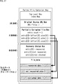
- FIG. 2 is a diagram illustrating a first structure example of a file with a defect.
- a file with a defect is composed of a Partial File File Container Box with a Box structure of ISO base file format.
- Partial File Container Box a broadcast data file containing missing data received by the broadcast receiving unit 31 is encapsulated.
- Partial File Box Container is a top-level Box consisting of Top Level Box Index Index Box, Original Source URL Box, Partially Corrupted File Box, and file_data.
- Top Box Level Box Index Box information indicating the position of a box at a predetermined level is described.
- URL information is described as the acquisition destination information of the restoration file.
- Partially Corrupted File Box missing information indicating the position and size of missing data, repair information, and the like are described.
- the file_data is broadcast data in which dummy data is arranged in the missing data (Corrupted data) portion of the file received by the broadcast receiving unit 31. Therefore, the size of file_data is the same as the size of the file to be received by the broadcast receiving unit 31.
- FIG. 3 is a diagram illustrating a second structure example of a missing file.
- the structure of the missing file in FIG. 3 is the same as the structure in FIG. 2 except for file_data.
- the file_data in FIG. 3 is broadcast data in which dummy data is not arranged in the missing data portion of the file received by the broadcast receiving unit 31 and the missing data portion is packed.
- FIG. 4 is a diagram illustrating an example of syntax of the Partial File Container Box in FIGS. 2 and 3.
- the Top File Level Container Box Top Top Level Box Index Original Box and Original Box URL Box may or may not be arranged.
- Partially Corrupted File Box is a Box (mandatory Box) that is always placed.
- FIG. 5 is a diagram illustrating an example of syntax and semantics of Original Source URL Box. Specifically, FIG. 5A is a diagram illustrating an example of the syntax of Original Source URL Box, and FIG. 5B is a diagram illustrating an example of semantics.
- URL information (url) of a repair file corresponding to file_data is described in Original ⁇ ⁇ Source URL Box.
- the HTTP reception unit 36 in FIG. 1 acquires a repair file from the HTTP server 13 based on the URL information.
- the restoration unit 35 replaces the dummy data of file_data with the broadcast data that is not missing of the restoration file corresponding to the dummy data. to repair.
- the restoration unit 35 restores the missing data by inserting broadcast data that does not exist in the file_data of the restoration file into the file_data.
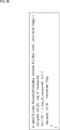
- FIG. 6 is a diagram illustrating an example of syntax of Partially Corrupted File Box
- FIG. 7 is a diagram illustrating an example of semantics.
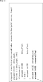
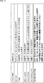
- “version” and “flags” are described in the Partially Corrupted File Box. As shown in FIG. 7, “version” is information indicating the version of this Partially Corrupted File Box. “Flags” includes a PCFB_BYTES_REMOVED flag, an All_Corrupted_Data_was_tried_to_recover flag, and a NOW_recovering flag.
- the PCFB_BYTES_REMOVED flag is a flag indicating whether or not dummy data exists in file_data, in which a value is set in the least significant bit of flags.
- the PCFB_BYTES_REMOVED flag is 1 when indicating that dummy data does not exist in file_data, and 0 when dummy data exists in file_data. That is, when the structure of the file with missing is the structure of FIG. 3, the PCFB_BYTES_REMOVED flag is set to 1, and when the structure of the file with missing is the structure of FIG. 2, the PCFB_BYTES_REMOVED flag is set to 0.
- the All_Corrupted_Data_was_tried_to_recover flag is a flag that is set in the second bit from the bottom of flags and indicates whether or not repair of all missing data in file_data has been completed at least once, and is one piece of repair information.
- the All_Corrupted_Data_was_tried_to_recover flag is 1 when it indicates that the repair of all missing data in file_data has been completed at least once, and 0 when it indicates that it has not been completed yet.
- the NOW_recovering flag is a flag that is set in the third bit from the bottom of flags and indicates whether all missing data in file_data is being repaired, and is one piece of repair information.
- the NOW_recovering flag is 1 when indicating that all missing data in file_data is being repaired, and 0 when indicating that it is not in the middle.
- the All_Corrupted_Data_was_tried_to_recover flag and NOW_recovering flag are set to 0. If all missing data in file_data has been repaired but is still being repaired, the All_Corrupted_Data_was_tried_to_recover flag is set to 0, but the NOW_recovering flag is set to 1. Furthermore, when all the missing data in file_data is repaired at least once, the All_Corrupted_Data_was_tried_to_recover flag is set to 1, but the NOW_recovering flag is set to 0.
- entry_count and num_of_recovered are also described in Partially Corrupted File Box. As shown in FIG. 7, entry_count is the number of missing data in file_data. num_of_recovered is information indicating the number of missing data that has been repaired, and is one piece of repair information.
- the flags All_Corrupted_Data_was_tried_to_recover and NOW_recovering are 0.
- the All_Corrupted_Data_was_tried_to_recover flag in flags is 0 and the NOW_recovering flag is 1.
- the All_Corrupted_Data_was_tried_to_recover flag in flags is 1 and the NOW_recovering flag is 0.
- byte_offset is offset information indicating the start position of missing data as an offset amount from the beginning of file_data.
- version is 1
- bit length of the offset information is 64 bits, and when it is not 1, it is 32 bits.
- Corrupted_size is information indicating the size of missing data.
- num_of_recovered is information indicating the number of entries from the beginning corresponding to the missing data that has been repaired last.
- the repair unit 35 determines whether the repair target file has not been repaired based on the flags of the repair target file. It can be recognized whether it is present or completed. In addition, when the repair of the repair target file is interrupted, the repair unit 35 can restart the repair from the interrupt position based on the entry_count of the repair target file.
- FIG. 8 is a flowchart for explaining file generation processing of the receiving device 12 of FIG. This file generation process is started when a broadcast data file is transmitted from the broadcast station 11.
- the broadcast reception unit 31 of the reception device 12 receives a broadcast data file transmitted from the broadcast station 11 via an antenna (not shown) and supplies the file to the file generation unit 32.
- step S12 the file generation unit 32 determines whether or not missing data exists in the broadcast data file supplied from the broadcast receiving unit 31.
- step S13 the file generation unit 32 generates a missing file from the broadcast data by using a method of Partial File Storage.
- step S14 the setting unit 33 sets the default value of the repair information in the Partially Corrupted File File Box of the missing file generated by the file generation unit 32. Note that the default value of the repair information is 0.
- step S15 the setting unit 33 supplies the recording unit 34 with the missing file in which the default value of the repair information is set, and records the file. Then, the process ends.
- step S16 the file generation unit 32 generates a missing file from the broadcast data.
- step S17 the file generation unit 32 supplies the missing file to the recording unit 34 and records it. Then, the process ends.
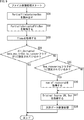
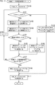
- FIG. 9 is a flowchart for explaining the file restoration process of the receiving device 12 of FIG. This file repair process is started, for example, when the repair unit 35 selects one of the missing files recorded in the recording unit 34 as a repair target file.
- the restoration unit 35 of the receiving device 12 reads the partial file container container box of the file to be restored recorded in the recording unit 34.
- the repair unit 35 acquires Partially Corrupted File File Box from the Partial File File Container box read out in Step S31.
- step S33 the repair unit 35 acquires flags from the Partially Corrupted File box acquired in Step S32.
- step S34 the restoration unit 35 determines whether the All_Corrupted_Data_was_tried_to_recover flag is set to 1 based on flags, that is, whether 1 is set in the second bit from the bottom of flags.
- step S34 If it is determined in step S34 that the All_Corrupted_Data_was_tried_to_recover flag is set to 1, that is, if all of the missing data in the repair target file has been repaired at least once, the process ends.
- step S34 if it is determined in step S34 that the All_Corrupted_Data_was_tried_to_recover flag is not set to 1, that is, if repair of all missing data in the repair target file has not been completed yet, the process proceeds to step S35.
- step S35 the restoration unit 35 determines, based on flags, whether the NOW_recovering flag is set to 1, that is, whether 1 is set in the third bit from the bottom of flags.
- step S35 If it is determined in step S35 that the NOW_recovering flag is set to 1, that is, if the repair of all missing data in the repair target file is interrupted, the process proceeds to step S36.
- step S36 the restoration unit 35 acquires num_of_recovered from the Partially Corrupted File box acquired in step S32, and advances the processing to step S37.
- step S35 determines that the NOW_recovering flag is not set to 1, that is, if the repair of all missing data of the repair target file has not yet started, the repair unit 35 determines that num_of_recovered is 0. recognize. Then, the process proceeds to step S37.
- step S35 when it is determined in step S35 that the NOW_recovering flag is not set to 1, the restoration unit 35 recognizes that num_of_recovered is 0, but from Partially Corrupted File File Box, num_of_recovered As a result, 0 may be acquired.
- step S37 the restoration unit 35 obtains Original Source URL Box from the read Partial File Container Box.
- step S38 the repair unit 35 performs a missing data repair process for repairing the missing data in the repair target file in order. Details of this missing data repair processing will be described with reference to FIG.
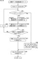
- FIG. 10 is a flowchart for explaining the details of the missing data repair process in step S38 of FIG.
- step S51 of FIG. 10 the restoration unit 35 sets the count value i to a value obtained by adding 1 to the acquired or recognized num_of_recovered.
- step S ⁇ b> 52 the restoration unit 35 determines whether the count value i is equal to or less than entry_count included in Partially Corrupted File Box.
- step S52 When it is determined in step S52 that the count value is equal to or smaller than entry_count, that is, when the repair of all the missing data of the repair target file has not yet been completed, the repair unit 35 is i th from the beginning of the Partially Corrupted File File Box. The missing data corresponding to the entry is determined as the data to be repaired.
- step S53 the restoration unit 35 supplies the URL information described in Original Source URL Box to the HTTP receiving unit 36, thereby corresponding to the i-th entry of the restoration file held in the HTTP server 13. Broadcast data to be acquired is acquired as repair data via the HTTP receiver 36.
- step S54 the repair unit 35 repairs the repair target data corresponding to the entry based on the missing information and the repair data of the i-th entry from the beginning described in Partially Corrupted File File Box. Then, the restoration unit 35 supplies the count value i to the setting unit 33 as restored information.
- step S55 the restoration unit 35 determines whether to stop the missing data restoration process. If it is determined in step S55 that the missing data repair process is not to be stopped, the repair unit 35 increments the count value by 1 in step S56. Then, the process returns to step S52.
- step S55 if it is determined in step S55 that the missing data repair process is to be stopped, the process proceeds to step S57.
- step S57 the setting unit 33 sets (updates) the NOW_recovering flag of the repair target file recorded in the recording unit 34, and advances the process to step S59.
- step S52 If it is determined in step S52 that the count value is larger than entry_count, that is, if the restoration of all missing data is completed, the process proceeds to step S58.
- step S58 the setting unit 33 sets the All_Corrupted_Data_was_tried_to_recover flag of the repair target file recorded in the recording unit 34 to 1 and sets the NOW_recovering flag to 0. Then, the process proceeds to step S59.
- step S59 the setting unit 33 sets the count value i represented by the repaired information supplied from the repair unit 35 to num_of_recovered of the repair target file recorded in the recording unit 34. Then, the process returns to step S38 in FIG. 9, and the process ends.
- the receiving device 12 sets the repair information of the file with the defect, the repair state of the file with the defect can be easily recognized when the file with the defect is repaired. As a result, the receiving device 12 can repair the repaired data again when the repair of the defective file whose repair has been interrupted is resumed, or repair the data that has failed to be repaired many times. Therefore, the repair can be resumed appropriately from the interrupt position. As a result, the load of the file repair process is reduced.
- the receiving device recognizes the state when the repair is suspended when repair is resumed by performing entry_count update and deletion of missing information at the same time as repair. Can do.
- this processing is complicated, and the size of the Partially Corrupted File Box is changed as a result of the processing, so it is necessary to rewrite data after the Partially Corrupted File Box. Therefore, the load of the file repair process is large.
- FIG. 11 is a diagram showing an example of the syntax of Partially Corrupted File Box in the second embodiment
- FIG. 12 is a diagram showing an example of semantics.
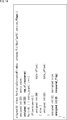
- Partially Corrupted File File Boxes in FIGS. 11 and 12 is that flags are composed of only the PCFB_BYTES_REMOVED flag, num_of_recovered is not described, and recovered_flag is newly described for each entry.
- the configuration is different. That is, the repair information in the second embodiment is recovered_flag, not flags and num_of_recovered.
- “Recovered_flag” of each entry is a flag indicating the state in which the repair of the missing data corresponding to the entry is successful, the state in which the repair has failed, or the state in which the repair has not been performed, and is repair information.
- the recovered_flag is composed of a Recovered flag and a Failed_to_recover flag.
- the Recovered flag is a flag that indicates whether or not the repair is successful, in which a value is set in the least significant bit of recovered_flag.
- the Recovered flag is 1 when indicating that the repair is successful, and is 0 when indicating that the repair is not successful.
- the Failed_to_recover flag is a flag that indicates whether or not the repair has failed, in which a value is set in the second bit from the bottom of the recovered_flag.
- the Failed_to_recover flag is 1 when indicating that the repair has failed, and 0 when indicating that the repair has not failed.
- the repair unit 35 executes the repair of the missing data corresponding to the entry based on the recovered_flag of each entry of the repair target file. And the presence or absence of success.
- the file generation process in the second embodiment is the same as the file generation process of FIG.
- FIG. 13 is a flowchart for explaining the file restoration processing of the receiving device 12 in the second embodiment.
- step S73 is the same as the processing in step S37 in FIG.
- step S74 the restoration unit 35 of the receiving device 12 sets the count value i to 1.
- step S75 the restoration unit 35 acquires recovered_flag of the i-th entry from the top described in Partially Corrupted File Box acquired in step S72.
- step S76 the restoration unit 35 determines whether the recovered_flag acquired in step S75 is 0, that is, whether the Recovered flag and the Failed_to_recover flag are 0.
- step S76 If it is determined in step S76 that recovered_flag is 0, that is, if the missing data corresponding to the i-th entry has not yet been repaired, the restoration unit 35 provides the missing data corresponding to the i-th entry. Is determined as data to be repaired.
- step S77 the restoration unit 35 supplies the URL information described in Original Source URL Box to the HTTP reception unit 36, thereby corresponding to the i-th entry of the restoration file held in the HTTP server 13. Broadcast data to be acquired is acquired as repair data via the HTTP receiver 36.
- step S78 the repair unit 35 repairs the repair target data corresponding to the entry based on the missing information and the repair data of the i-th entry.
- step S79 the restoration unit 35 determines whether or not the restoration in step S78 is successful. For example, if the restoration file 35 does not exist in the HTTP server 13 corresponding to the URL information described in Original Source URL Box and acquisition of the restoration file has failed in step S77, the restoration unit 35 35 determines that the repair is not successful.
- step S79 If it is determined in step S79 that the repair is successful, the repair unit 35 supplies the setting unit 33 with repair result information indicating the successful repair of the repair target data corresponding to the i-th entry.
- step S80 the setting unit 33 sets the Recovered flag of the i-th entry of the repair target file recorded in the recording unit 34 to 1, and advances the process to step S82.
- the repair unit 35 supplies the setting unit 33 with repair result information indicating a repair failure of the repair target data corresponding to the i-th entry.
- step S81 the setting unit 33 sets the Failed_to_recover flag of the i-th entry of the repair target file recorded in the recording unit 34 to 1, and advances the process to step S82.
- step S76 If it is determined in step S76 that recovered_flag is not 0, that is, if the missing data corresponding to the i-th entry has already been repaired, the process proceeds to step S82.
- step S82 the restoration unit 35 determines whether or not to stop the file restoration process. If it is determined in step S82 that the file repair process is not stopped, the process proceeds to step S83. In step S83, the setting unit 33 increments the count value i by 1.
- step S84 the setting unit 33 determines whether or not the count value i is equal to or smaller than entry_count described in Partially Corrupted File Box. If it is determined in step S84 that the count value i is equal to or smaller than entry_count, the process returns to step S75, and the subsequent processes are repeated.
- step S82 if it is determined in step S82 that the file repair process is to be stopped, the process ends. If it is determined in step S84 that the count value i is greater than entry_count, that is, if all missing data has been repaired, the process ends.
- the repair information is information indicating a state where the repair of each missing data is successful, a state where it has failed, or a state where it has not been performed. Therefore, the receiving device 12 can recognize not only whether or not each missing data is repaired but also whether or not the repair is successful.
- the third embodiment of the information processing system to which the present disclosure is applied is a combination of the first embodiment and the second embodiment. That is, in the third embodiment, the repair information is flags, num_of_recovered, and recovered_flag, and the repaired information and the repair result information are supplied from the repair unit 35 to the setting unit 33. Therefore, in the following, only the processes relating to the repair information, the repaired information, and the repair result information will be described using the respective parts in FIG. 1 as the respective parts of the third embodiment of the information processing system.
- FIG. 14 is a diagram showing an example of the syntax of Partially Corrupted File Box in the third embodiment.
- Partially Corrupted File Box in FIG. 14 differs from the configuration in FIG. 6 in that recovered_flag is newly described for each entry.
- the file generation process in the third embodiment is the same as the file generation process of FIG. Further, the file repair process in the third embodiment is the same as the file repair process of FIG. 9 except for the missing data repair process in step S38, so only the missing data repair process will be described below.
- FIG. 15 is a flowchart for explaining the missing data repair process of the receiving device 12 in the third embodiment.
- steps S51 to S54 of FIG. 10 is the same as the processing of steps S51 to S54 of FIG. 10
- steps S104 to S106 is the same as the processing of steps S79 to S81 of FIG.
- steps S107 to S111 is the same as the processing in steps S55 to S59 in FIG.
- ⁇ Fourth embodiment> (First structure example of missing file)
- the fourth embodiment of the information processing system to which the present disclosure is applied is the same as the third embodiment except that the repair information is set in a new Box different from the Partially Corrupted File Box. Therefore, in the following, only the structure of a file with a defect will be described using each part of FIG. 1 as each part of the fourth embodiment of the information processing system.
- FIG. 16 is a diagram illustrating a first structure example of a missing file according to the fourth embodiment.
- the structure of a missing file in FIG. 16 is composed of two Boxes: Recovery Status Box where repair information is not described in Partially Corrupted File Box, and Partial File Container Box and repair information are placed in the missing file The point is different from the structure of FIG.
- Partially Corrupted File Box in FIG. 16 is the same as the syntax in FIG. 6 except that the flags are composed only of the PCFB_BYTES_REMOVED flag and num_of_recovered is not arranged, so the description is omitted.
- ⁇ Recovery Status Box is a Box in the same hierarchy as Partial File Container Box.
- FIG. 17 is a diagram illustrating a second structure example of a file with a defect according to the fourth embodiment.
- FIG. 17 The structure of the missing file in FIG. 17 is different from the structure of FIG. 16 in that the Recovery Status Box is placed in the Partial File Container box.
- the repair information is arranged in a Box different from the Partially Corrupted File Box, so that the repair information can be easily set.
- dummy data may not be arranged in file_data in the missing file of FIGS. 16 and 17 as in the case of FIG.
- FIG. 18 is a diagram illustrating an example of the syntax of the Partial File Container Box in FIG.
- FIG. 19 is a diagram illustrating a first example of the syntax of the Recovery Status Box in FIGS. 16 and 17.
- FIG. 20 is a diagram illustrating a second example of the syntax of the Recovery Status Box in FIGS. 16 and 17.
- Recovery Status Box in FIG. 20 is different from the syntax in FIG. 19 in that entry_count is not described and only the recovered_flag of missing data that has been repaired out of missing data in file_data is arranged. .
- either the recovered flag or the failed_to_recover flag of recovered_flag is always set to 1. That is, recovered_flag does not become 0 indicating a state in which restoration is not performed.
- the repair information of the third embodiment is set to a new Box different from Partially Corrupted File File Box, but the repair information of the first embodiment or the second embodiment is Partially It may be set to a new Box different from Corrupted File Box.
- the file generation unit 32 includes an MPD (Media Presentation Description) of the file.
- MPD Media Presentation Description
- the configuration of the first to fourth embodiments, except that the file is set with missing file information for identifying the missing file and the setting unit 33 also sets the repair information for the MPD file. Is the same. Therefore, in the following, only the processing relating to the MPD file will be described using the respective units in FIG. 1 as respective units in the fifth embodiment of the information processing system.
- FIG. 21 is a diagram for explaining the processing of the file generation unit 32 in the fifth embodiment.
- the broadcast data file is a file conforming to MPEG-DASH
- the file is segmented, and one Initialization Segment file, one or more (n in the example of FIG. 21) Media It consists of a Segment file and an MPD file (not shown).
- a Segment file when there is no need to distinguish between the Initialization Segment file and the MediaSSegment file, they are collectively referred to as a Segment file.
- the file generation unit 32 determines whether missing data exists in the Segment file supplied from the broadcast reception unit 31.
- the file generation unit 32 determines the missing file from the broadcast data of the Media Segment file. Generate.
- a missing file is generated as in the first to third embodiments, but a missing file including RecoveryReStatus Box is generated as in the fourth embodiment. You may make it do.
- the file generation unit 32 sets the Segment file as it is as a missing file.
- the file generation unit 32 supplies the generated missing file and missing file to the recording unit 34 for recording.
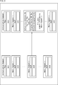
- FIG. 22 is a diagram illustrating a first configuration example of an MPD file in which missing file information and repair information are set.
- the MPD file is a file that manages the Segment file.
- information such as encoding information (Configuration information) of broadcast data, image size, audio language, etc. are layered and described in XML format.
- hierarchization in the MPD file is performed using elements such as a period, an adaptation set, and a representation.
- the broadcast data stored in the Segment file that it manages is divided in a predetermined time range.
- the period element is described for each divided broadcast data.
- the adaptation set element is included in the period element and groups representation elements of broadcast data corresponding to the period element.
- the representation elements are grouped according to the type of broadcast data (image, sound in the example of FIG. 22A).
- the representation element has URL information of the acquisition destination of the divided broadcast data.
- ⁇ EssentialProperty schemeIdUri “urn: mpeg: dash: corrupted: 2015”> is an EssentialProperty indicating that at least one of the Segment files corresponding to the representation element included in the element including the element is a missing file.
- at least one of all the segment files (video.mp4, audio.mp4) managed by the MPD file is a missing file.
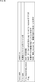
- file_name is information indicating the file name of a file with a defect as missing file information.
- the file_recovered_status_flag is composed of an All_Corrupted_data_was_tired_to_recover flag and a NOW_recovering flag as repair information for the missing file.
- the setting unit 33 sets not only the repair information set in the missing file recorded in the recording unit 34 but also the repair information set in the MPD file based on the repaired information supplied from the repair unit 35. Also update.
- FIG. 24 is a diagram illustrating a second configuration example of the MPD file in which the missing file information and the repair information are set.
- the file generation unit 32 uses a method called Partial File Storage as shown in A of FIG.
- the MPD file supplied from the broadcast receiving unit 31 is encapsulated.
- the file generation unit 32 stores the MPD file supplied from the broadcast receiving unit 31 in the Original MPD element, and stores the Original MPD element in the Encapsulated MPD element. Therefore, the restoration unit 35 can recognize whether or not at least one of the segment files managed by the MPD file is a missing file depending on whether or not the Encapsulated MPD element exists in the MPD file.
- the setting unit 33 sets not only the repair information set in the missing file recorded in the recording unit 34 but also the repair information set in the MPD file based on the repaired information supplied from the repair unit 35. Also update.
- missing file information and repair information are set in the MPD file. Therefore, the repair unit 35 can recognize a missing file that has not been repaired and is recorded in the recording unit 34 only by acquiring the MPD file. Therefore, the repairing unit 35 can repair a missing file that has not been repaired without wastefully reading the missing file that has been repaired.
- a playback device that plays back a file with a defect recorded in the recording unit 34 can recognize a file with a defect that has been repaired by only acquiring the MPD file. Therefore, the playback device can play back a file with a defect that has been repaired without wastefully reading a file with a defect that has not been repaired.
- ⁇ Sixth embodiment> (Description of processing of file generation unit)
- the setting unit 33 sets the repair information in the Corrupted File Index file
- the file generation unit 32 is the same as that of the fifth embodiment except that the MPD file sets not the missing file information and the repair information, but the Corrupted File Index file information that identifies the Corrupted File Index file. Therefore, in the following, only the processing related to the Corrupted File Index file and the MPD file will be described using the respective units in FIG. 1 as the respective units of the sixth embodiment of the information processing system.
- FIG. 25 is a diagram for explaining the processing of the file generation unit 32 in the sixth embodiment.
- the file generation unit 32 determines whether or not missing data exists in the Segment file supplied from the broadcast reception unit 31 as in the fifth embodiment. As shown in FIG. 25, when it is determined that missing data exists in the xth and yth Media Segment files (Media Segment x, Media Segment y) from the beginning, the file generation unit 32 broadcasts the Media Segment file. Generate missing files from the data.
- a file with a defect having the configuration of FIG. 17 is generated.
- a file with a defect whose repair information is set in Partially Corrupted File File Box. May be generated.
- a file with a defect in which repair information is set in a Recovery Status box different from a Partial File Status Container Box may be generated.
- the file generation unit 32 uses the Segment file as it is as a missing file.
- the file generation unit 32 supplies the generated missing file and missing file to the recording unit 34 for recording.
- the file generation unit 32 generates a new Corrupted File Index file that is different from the broadcast data file.
- the setting unit 33 sets the repair information of each missing file as File Recovery Status Box in the generated Corrupted File Index file.
- FIG. 26 is a diagram illustrating an example of the syntax of the File Recovery Status Box.
- Corrupted File Index file has a missing File Recovery Status box for each file. As shown in FIG. 26, file_name, file_recovered_status_flag, and Recovery Status Box are described in File Recovery Status Box.
- Recovery Status Box does not have to be placed in the File Recovery Status Box.
- Recovery Status Box does not have to be placed in a missing file.
- FIG. 27 is a diagram illustrating a configuration example of an MPD file in which Corrupted File Index file information is set.
- the file generation unit 32 When the file generation unit 32 acquires the MPD file of FIG. 27A from the broadcast reception unit 31 and there is missing data in at least one of the segment files, the file generation unit 32 stores the Corrupted File Index file in the MPD file. Information indicating the file name is set as Corrupted File Index file information.
- FIG. 28 is a diagram for explaining the processing of the file generation unit 32 in the seventh embodiment.
- the file generation unit 32 determines whether or not missing data exists in the Segment file supplied from the broadcast reception unit 31 as in the sixth embodiment. As shown in FIG. 28, when it is determined that there is missing data in the xth and yth Media Segment files (Media Segment x, Media Segment y) from the beginning, the file generation unit 32 broadcasts the Media Segment file. Generate missing files from the data.
- the file generation unit 32 generates a missing file from the InitializationInSegment file regardless of whether or not missing data exists in the Initialization ⁇ ⁇ ⁇ ⁇ Segment file.
- the setting unit 33 sets repair information of all the missing files as Segment Corrupted Information Box in the missing file generated from the Initialization Segment file (hereinafter referred to as a missing Initialization Segment file).
- the file generation unit 32 supplies the generated missing file and missing file to the recording unit 34 for recording.
- the missing file having the configuration of FIG. 17 is generated, but the missing file in which the repair information is set in Partially Corrupted File File as in the first to third embodiments. May be generated. Further, as shown in FIG. 16, a file with a defect in which repair information is set in a Recovery Status box different from a Partial File Status Container Box may be generated.
- FIG. 29 is a diagram illustrating a configuration example of a defective initialization segment file.
- the configuration of the missing initialization segment file in FIG. 29 is the same as the configuration of the missing file in FIG. 18 except that the segment corrupted information box is arranged.
- FIG. 30 is a diagram illustrating an example of the syntax of the Segment Corrupted Information Box in FIG.
- a File Recovery Status box is arranged for each missing file.
- ⁇ EssentialProperty schemeIdUri “urn: mpeg: dash: corrupted: index: initialization: 2015”> indicates that at least one of the Segment files managed by the MPD file is a missing file, and the repair information for the missing file is an Initialization Segment file It is an EssentialProperty indicating that it is set to.
- restoration information is set in the Initialization Segment file that is reproduced before the Media Segment file when the Media Segment file is reproduced. Therefore, the playback device can recognize the repair information of the Media Segment file before playing the Media Segment file.
- FIG. 31 is a block diagram illustrating a configuration example of an eighth embodiment of an information processing system to which the present disclosure is applied.
- the cache proxy 51 receives and stores a broadcast data file compliant with MPEG-DASH, and the player 52 reproduces the file stored in the cache proxy 51.
- the cache proxy 51 of the information processing system 50 is, for example, a home server for home use, and includes the receiving device 12 and the DASH server 61.
- the receiving device 12 receives and records a broadcast data file compliant with MPEG-DASH transmitted from the broadcast station 11, and restores missing data in the file.
- the DASH server 61 acquires and stores a missing file and a missing file for which all of the missing data recorded in the recording unit 34 of the receiving device 12 has been repaired.
- the player 52 includes a DASH client 71 and the like.
- the DASH client 71 (playback unit) reads the MPD file stored in the DASH server 61.
- the DASH client 71 refers to the MPD file, reads a necessary segment file from the DASH server 61, and reproduces broadcast data acquired based on the segment file.
- FIG. 32 is a block diagram illustrating a configuration example of the ninth embodiment of the information processing system to which the present disclosure has been applied.
- the cache proxy 101 is provided instead of the cache proxy 51 and the player 102 is provided instead of the player 52. Different.
- the player 102 performs restoration.
- the cache proxy 101 of the information processing system 100 is, for example, a home server for home use, and includes a broadcast receiving unit 31, a file generating unit 32, a setting unit 111, and a DASH server 112.
- the setting unit 111 performs a process of setting a default value of repair information in the process of the setting unit 33 in FIG.
- the DASH server 112 records the non-missing file generated by the file generating unit 32 and the missing file and the MPD file in which the default value of the repair information is set in at least one of them.
- the player 102 includes a recording unit 34, a restoration unit 35, an HTTP reception unit 36, a DASH client 121, and a setting unit 122.
- the DASH client 121 (playback unit) reads the MPD file recorded in the DASH server 112.
- the DASH client 121 refers to the MPD file, reads a necessary Segment file from the DASH server 112, and records it in the recording unit 34.
- the DASH client 121 reads a segment file in which all missing data recorded in the recording unit 34 has been repaired, acquires broadcast data based on the segment file, and plays it back.
- the setting unit 122 performs a process of updating the repair information in the process of the setting unit 33 in FIG.
- ⁇ Tenth embodiment> (Description of computer to which the present disclosure is applied)
- the series of processes of the receiving device 12 described above can be executed by hardware or can be executed by software.
- a program constituting the software is installed in the computer.
- the computer includes, for example, a general-purpose personal computer capable of executing various functions by installing various programs by installing a computer incorporated in dedicated hardware.
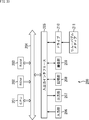
- FIG. 33 is a block diagram illustrating a configuration example of hardware of a computer that executes the series of processes of the receiving device 12 described above by a program.
- a CPU Central Processing Unit
- ROM Read Only Memory
- RAM Random Access Memory
- An input / output interface 205 is further connected to the bus 204.
- An input unit 206, an output unit 207, a storage unit 208, a communication unit 209, and a drive 210 are connected to the input / output interface 205.
- the input unit 206 includes a keyboard, a mouse, a microphone, and the like.
- the output unit 207 includes a display, a speaker, and the like.
- the storage unit 208 includes a hard disk, a nonvolatile memory, and the like.
- the communication unit 209 includes a network interface and the like.
- the drive 210 drives a removable medium 211 such as a magnetic disk, an optical disk, a magneto-optical disk, or a semiconductor memory.
- the CPU 201 loads the program stored in the storage unit 208 to the RAM 203 via the input / output interface 205 and the bus 204 and executes the program. A series of processing is performed.
- the program executed by the computer 200 can be provided by being recorded in, for example, a removable medium 211 such as a package medium.
- the program can be provided via a wired or wireless transmission medium such as a local area network, the Internet, or digital satellite broadcasting.
- the program can be installed in the storage unit 208 via the input / output interface 205 by attaching the removable medium 211 to the drive 210.
- the program can be received by the communication unit 209 via a wired or wireless transmission medium and installed in the storage unit 208.
- the program can be installed in the ROM 202 or the storage unit 208 in advance.
- the program executed by the computer 200 may be a program that is processed in time series in the order described in this specification, or a necessary timing such as in parallel or when a call is made. It may be a program in which processing is performed.
- the system means a set of a plurality of components (devices, modules (parts), etc.), and it does not matter whether all the components are in the same housing. Accordingly, a plurality of devices housed in separate housings and connected via a network and a single device housing a plurality of modules in one housing are all systems. .
- the same description as the Segment Corrupted Information Box may be performed in the MPD file.
- the present technology is applied not only to a device that receives broadcast data, but also to a device (for example, a portable terminal) that receives data multicast according to LTE (Long Term Evolution) or Wi-Fi. You can also.
- LTE Long Term Evolution
- Wi-Fi Wireless Fidelity
- this indication can also take the following structures.
- An information processing apparatus comprising: a repair unit that repairs the missing data based on the repair information set by the setting unit.
- the setting unit is configured to set the restoration information in a box different from a box in which data of the file is arranged.
- the setting unit is configured to set the repair information in a box different from a box in which missing information indicating a position and a size of the missing data is included in a box in which data of the file is arranged.
- the information processing apparatus configured to set the repair information in a repair information file that is a file different from the file.
- the setting unit is configured to set missing file specifying information for specifying the file in the repair information file.
- the information processing apparatus according to (9) or (10), further including: a file generation unit that sets information for specifying the repair information file in a management file for managing the file.
- the information processing apparatus according to any one of (9) to (11), wherein the repair information file is configured as an initialization segment file.
- the repair information is information indicating that all of the missing data in the file is being repaired.
- the information processing apparatus according to any one of (1) to (13), wherein the repair information is information indicating that repair of all the missing data of the file is completed.
- the repair information is information indicating the missing data that has been repaired by the repair unit.
- the repair information is configured to be information indicating a state in which the repair of each missing data has been successful, a state in which the repair has failed, or a state in which the repair has not been performed.
- the repair information is information indicating the missing data that has been repaired by the repair unit, and information indicating whether the repair of each missing data that has been repaired has succeeded or failed.
- Information processing device A setting step for setting repair information indicating the repair status of missing data in a file conforming to the ISO Base media file format; A repairing step of repairing the missing data based on the repair information set by the processing of the setting step.
- An information processing apparatus comprising: a playback unit that plays back the file in which repair information indicating a repair state of missing data of a file that conforms to the ISO Base media file format is set.
- Information processing device An information processing method including a reproduction step of reproducing the file in which restoration information indicating a restoration state of missing data of a file compliant with ISO Base media file format is set.
Landscapes
- Engineering & Computer Science (AREA)
- Theoretical Computer Science (AREA)
- Multimedia (AREA)
- Signal Processing (AREA)
- Quality & Reliability (AREA)
- Physics & Mathematics (AREA)
- General Engineering & Computer Science (AREA)
- General Physics & Mathematics (AREA)
- Computer Networks & Wireless Communication (AREA)
- Databases & Information Systems (AREA)
- Information Retrieval, Db Structures And Fs Structures Therefor (AREA)
- Two-Way Televisions, Distribution Of Moving Picture Or The Like (AREA)
Abstract
Description
1.第1実施の形態:情報処理システム(図1乃至図10)
2.第2実施の形態:情報処理システム(図11乃至図13)
3.第3実施の形態:情報処理システム(図14および図15)
4.第4実施の形態:情報処理システム(図16乃至図20)
5.第5実施の形態:情報処理システム(図21乃至図24)
6.第6実施の形態:情報処理システム(図25乃至図27)
7.第7実施の形態:情報処理システム(図28乃至図30)
8.第8実施の形態:情報処理システム(図31)
9.第9実施の形態:情報処理システム(図32)
10.第10実施の形態:コンピュータ(図33)
(情報処理システムの第1実施の形態の構成例)
図1は、本開示を適用した情報処理システムの第1実施の形態の構成例を示すブロック図である。
図2は、欠損ありファイルの第1の構造例を示す図である。
図3は、欠損ありファイルの第2の構造例を示す図である。
図4は、図2および図3のPartial File Container Boxのシンタックス(syntax)の例を示す図である。
図5は、Original Source URL Boxのシンタックスとセマンティクス(semantics)の例を示す図である。具体的には、図5のAは、Original Source URL Boxのシンタックスの例を示す図であり、図5のBは、セマンティクスの例を示す図である。
図6は、Partially Corrupted File Boxのシンタックスの例を示す図であり、図7は、セマンティクスの例を示す図である。
図8は、図1の受信装置12のファイル生成処理を説明するフローチャートである。このファイル生成処理は、放送局11から放送データのファイルが送信されてきたとき、開始される。
(Partially Corrupted File Boxのシンタックスとセマンティクスの例)
本開示を適用した情報処理システムの第2実施の形態は、修復情報、および、修復済み情報の代わりに各欠損データの修復の成功または失敗を表す修復結果情報が修復部35から設定部33に供給される点を除いて、第1実施の形態と同一である。従って、以下では、図1の各部を情報処理システムの第2実施の形態の各部として用いて、修復情報および修復結果情報に関する処理についてのみ説明する。
第2実施の形態におけるファイル生成処理は、図8のファイル生成処理と同様であるので、説明は省略する。
(Partially Corrupted File Boxのシンタックスの例)
本開示を適用した情報処理システムの第3実施の形態は、第1実施の形態および第2実施の形態を組み合わせたものである。即ち、第3実施の形態では、修復情報が、flags,num_of_recovered、およびrecovered_flagであり、修復済み情報と修復結果情報が修復部35から設定部33に供給される。従って、以下では、図1の各部を情報処理システムの第3実施の形態の各部として用いて、修復情報、修復済み情報、および修復結果情報に関する処理についてのみ説明する。
第3実施の形態におけるファイル生成処理は、図8のファイル生成処理と同様であるので、説明は省略する。また、第3実施の形態におけるファイル修復処理は、ステップS38の欠損データ修復処理を除いて図9のファイル修復処理と同様であるので、以下では、欠損データ修復処理についてのみ説明する。
(欠損ありファイルの第1の構造例)
本開示を適用した情報処理システムの第4実施の形態は、修復情報がPartially Corrupted File Boxとは異なる新たなBoxに設定される点を除いて、第3実施の形態と同一である。従って、以下では、図1の各部を情報処理システムの第4実施の形態の各部として用いて、欠損ありファイルの構造についてのみ説明する。
図17は、第4実施の形態における欠損ありファイルの第2の構造例を示す図である。
図18は、図17のPartial File Container Boxのシンタックスの例を示す図である。
図19は、図16および図17のRecovery Status Boxのシンタックスの第1の例を示す図である。
図20は、図16および図17のRecovery Status Boxのシンタックスの第2の例を示す図である。
(ファイル生成部の処理の説明)
本開示を適用した情報処理システムの第5実施の形態は、放送データのファイルがMPEG-DASHに準拠したファイルである場合に、ファイル生成部32が、そのファイルのうちのMPD(Media Presentation Description)ファイルに、欠損ありファイルを特定する欠損ファイル情報を設定する点と、設定部33が修復情報をMPDファイルにも設定する点とを除いて、第1実施の形態乃至第4実施の形態の構成と同一である。従って、以下では、図1の各部を情報処理システムの第5実施の形態の各部として用いて、MPDファイルに関する処理についてのみ説明する。
図22は、欠損ありファイル情報と修復情報が設定されたMPDファイルの第1の構成例を示す図である。
図24は、欠損ありファイル情報と修復情報が設定されたMPDファイルの第2の構成例を示す図である。
(ファイル生成部の処理の説明)
本開示を適用した情報処理システムの第6実施の形態は、放送データのファイルがMPEG-DASHに準拠したファイルである場合に、設定部33が修復情報をCorrupted File Indexファイルに設定する点と、ファイル生成部32が、MPDファイルに、欠損ファイル情報や修復情報ではなく、Corrupted File Indexファイルを特定するCorrupted File Indexファイル情報を設定する点とを除いて、第5実施の形態と同一である。従って、以下では、図1の各部を情報処理システムの第6実施の形態の各部として用いて、Corrupted File IndexファイルおよびMPDファイルに関する処理についてのみ説明する。
図26は、File Recovery Status Boxのシンタックスの例を示す図である。
図27は、Corrupted File Indexファイル情報が設定されたMPDファイルの構成例を示す図である。
(ファイル生成部の処理の説明)
本開示を適用した情報処理システムの第7実施の形態は、放送データのファイルがMPEG-DASHに準拠したファイルである場合に、修復情報が設定されるファイルが、Corrupted File Indexファイルではなく、Initialization Segmentファイルである点を除いて、第6実施の形態と同一である。従って、以下では、図1の各部を情報処理システムの第7実施の形態の各部として用いて、Initialization SegmentファイルおよびMPDファイルに関する処理についてのみ説明する。
図29は、欠損ありInitialization Segmentファイルの構成例を示す図である。
図30は、図29のSegment Corrupted Information Boxのシンタックスの例を示す図である。
(情報処理システムの第8実施の形態の構成例)
図31は、本開示を適用した情報処理システムの第8実施の形態の構成例を示すブロック図である。
(情報処理システムの第9実施の形態の構成例)
図32は、本開示を適用した情報処理システムの第9実施の形態の構成例を示すブロック図である。
(本開示を適用したコンピュータの説明)
上述した受信装置12の一連の処理は、ハードウエアにより実行することもできるし、ソフトウエアにより実行することもできる。一連の処理をソフトウエアにより実行する場合には、そのソフトウエアを構成するプログラムが、コンピュータにインストールされる。ここで、コンピュータには、専用のハードウエアに組み込まれているコンピュータや、各種のプログラムをインストールすることで、各種の機能を実行することが可能な、例えば汎用のパーソナルコンピュータなどが含まれる。
ISO Base media file formatに準拠したファイルの欠損データの修復の状態を示す修復情報を設定する設定部と、
前記設定部により設定された前記修復情報に基づいて、前記欠損データを修復する修復部と
を備える情報処理装置。
(2)
前記設定部は、前記ファイルのデータが配置されるボックスとは異なるボックスに前記修復情報を設定する
ように構成された
前記(1)に記載の情報処理装置。
(3)
前記設定部は、前記ファイルのデータが配置されるボックスに含まれる、前記欠損データの位置とサイズを表す欠損情報が配置されるボックスとは異なるボックスに前記修復情報を設定する
ように構成された
前記(1)に記載の情報処理装置。
(4)
前記設定部は、前記ファイルの前記欠損データの位置とサイズを表す欠損情報が配置されるボックスに前記修復情報を設定する
ように構成された
前記(1)に記載の情報処理装置。
(5)
前記設定部は、前記ファイルを管理する管理ファイルに前記修復情報を設定する
ように構成された
前記(1)乃至(4)のいずれかに記載の情報処理装置。
(6)
前記管理ファイルはカプセル化される
ように構成された
前記(5)に記載の情報処理装置。
(7)
前記ファイルを特定する欠損ファイル情報を、前記ファイルを管理する管理ファイルに設定するファイル生成部
をさらに備える
前記(1)乃至(4)のいずれかに記載の情報処理装置。
(8)
前記管理ファイルは、カプセル化される
ように構成された
前記(7)に記載の情報処理装置。
(9)
前記設定部は、前記ファイルとは異なるファイルである修復情報ファイルに前記修復情報を設定する
ように構成された
前記(1)に記載の情報処理装置。
(10)
前記設定部は、前記修復情報ファイルに前記ファイルを特定する欠損ファイル特定情報を設定する
ように構成された
前記(9)に記載の情報処理装置。
(11)
前記修復情報ファイルを特定する情報を、前記ファイルを管理する管理ファイルに設定するファイル生成部
をさらに備える
前記(9)または(10)に記載の情報処理装置。
(12)
前記修復情報ファイルは、Initialization Segmentファイルである
ように構成された
前記(9)乃至(11)のいずれかに記載の情報処理装置。
(13)
前記修復情報は、前記ファイルの全ての前記欠損データの修復の途中であることを示す情報である
ように構成された
前記(1)乃至(12)のいずれかに記載の情報処理装置。
(14)
前記修復情報は、前記ファイルの全ての前記欠損データの修復が完了したことを示す情報である
ように構成された
前記(1)乃至(13)のいずれかに記載の情報処理装置。
(15)
前記修復情報は、前記修復部により前記修復が行われた前記欠損データを示す情報である
ように構成された
前記(1)乃至(14)のいずれかに記載の情報処理装置。
(16)
前記修復情報は、各欠損データの前記修復が成功した状態、前記修復が失敗した状態、または前記修復が行われていない状態を示す情報である
ように構成された
前記(1)乃至(15)のいずれかに記載の情報処理装置。
(17)
前記修復情報は、前記修復部により前記修復が行われた前記欠損データを示す情報と、前記修復が行われた各欠損データの前記修復が成功したか、または、失敗したかを示す情報である
ように構成された
前記(1)乃至(14)のいずれかに記載の情報処理装置。
(18)
情報処理装置が、
ISO Base media file formatに準拠したファイルの欠損データの修復の状態を示す修復情報を設定する設定ステップと、
前記設定ステップの処理により設定された前記修復情報に基づいて、前記欠損データを修復する修復ステップと
を含む情報処理方法。
(19)
ISO Base media file formatに準拠したファイルの欠損データの修復の状態を示す修復情報が設定された前記ファイルを再生する再生部
を備える情報処理装置。
(20)
情報処理装置が、
ISO Base media file formatに準拠したファイルの欠損データの修復の状態を示す修復情報が設定された前記ファイルを再生する再生ステップ
を含む情報処理方法。
Claims (20)
- ISO Base media file formatに準拠したファイルの欠損データの修復の状態を示す修復情報を設定する設定部と、
前記設定部により設定された前記修復情報に基づいて、前記欠損データを修復する修復部と
を備える情報処理装置。 - 前記設定部は、前記ファイルのデータが配置されるボックスとは異なるボックスに前記修復情報を設定する
ように構成された
請求項1に記載の情報処理装置。 - 前記設定部は、前記ファイルのデータが配置されるボックスに含まれる、前記欠損データの位置とサイズを表す欠損情報が配置されるボックスとは異なるボックスに前記修復情報を設定する
ように構成された
請求項1に記載の情報処理装置。 - 前記設定部は、前記ファイルの前記欠損データの位置とサイズを表す欠損情報が配置されるボックスに前記修復情報を設定する
ように構成された
請求項1に記載の情報処理装置。 - 前記設定部は、前記ファイルを管理する管理ファイルに前記修復情報を設定する
ように構成された
請求項1に記載の情報処理装置。 - 前記管理ファイルは、カプセル化される
ように構成された
請求項5に記載の情報処理装置。 - 前記ファイルを特定する欠損ファイル情報を、前記ファイルを管理する管理ファイルに設定するファイル生成部
をさらに備える
請求項1に記載の情報処理装置。 - 前記管理ファイルは、カプセル化される
ように構成された
請求項7に記載の情報処理装置。 - 前記設定部は、前記ファイルとは異なるファイルである修復情報ファイルに前記修復情報を設定する
ように構成された
請求項1に記載の情報処理装置。 - 前記設定部は、前記修復情報ファイルに前記ファイルを特定する欠損ファイル特定情報を設定する
ように構成された
請求項9に記載の情報処理装置。 - 前記修復情報ファイルを特定する情報を、前記ファイルを管理する管理ファイルに設定するファイル生成部
をさらに備える
請求項9に記載の情報処理装置。 - 前記修復情報ファイルは、Initialization Segmentファイルである
ように構成された
請求項9に記載の情報処理装置。 - 前記修復情報は、前記ファイルの全ての前記欠損データの修復の途中であることを示す情報である
ように構成された
請求項1に記載の情報処理装置。 - 前記修復情報は、前記ファイルの全ての前記欠損データの修復が完了したことを示す情報である
ように構成された
請求項1に記載の情報処理装置。 - 前記修復情報は、前記修復部により前記修復が行われた前記欠損データを示す情報である
ように構成された
請求項1に記載の情報処理装置。 - 前記修復情報は、各欠損データの前記修復が成功した状態、前記修復が失敗した状態、または前記修復が行われていない状態を示す情報である
ように構成された
請求項1に記載の情報処理装置。 - 前記修復情報は、前記修復部により前記修復が行われた前記欠損データを示す情報と、前記修復が行われた各欠損データの前記修復が成功したか、または、失敗したかを示す情報である
ように構成された
請求項1に記載の情報処理装置。 - 情報処理装置が、
ISO Base media file formatに準拠したファイルの欠損データの修復の状態を示す修復情報を設定する設定ステップと、
前記設定ステップの処理により設定された前記修復情報に基づいて、前記欠損データを修復する修復ステップと
を含む情報処理方法。 - ISO Base media file formatに準拠したファイルの欠損データの修復の状態を示す修復情報が設定された前記ファイルを再生する再生部
を備える情報処理装置。 - 情報処理装置が、
ISO Base media file formatに準拠したファイルの欠損データの修復の状態を示す修復情報が設定された前記ファイルを再生する再生ステップ
を含む情報処理方法。
Priority Applications (4)
| Application Number | Priority Date | Filing Date | Title |
|---|---|---|---|
| US15/747,964 US20180232287A1 (en) | 2015-10-09 | 2016-09-27 | Information processing apparatus and information processing method |
| EP16853453.5A EP3319327A4 (en) | 2015-10-09 | 2016-09-27 | Information processing apparatus and information processing method |
| JP2017544459A JP6834967B2 (ja) | 2015-10-09 | 2016-09-27 | 情報処理装置および情報処理方法 |
| CN201680057561.2A CN108141640B (zh) | 2015-10-09 | 2016-09-27 | 信息处理设备和信息处理方法 |
Applications Claiming Priority (2)
| Application Number | Priority Date | Filing Date | Title |
|---|---|---|---|
| JP2015201344 | 2015-10-09 | ||
| JP2015-201344 | 2015-10-09 |
Publications (1)
| Publication Number | Publication Date |
|---|---|
| WO2017061299A1 true WO2017061299A1 (ja) | 2017-04-13 |
Family
ID=58487498
Family Applications (1)
| Application Number | Title | Priority Date | Filing Date |
|---|---|---|---|
| PCT/JP2016/078352 Ceased WO2017061299A1 (ja) | 2015-10-09 | 2016-09-27 | 情報処理装置および情報処理方法 |
Country Status (5)
| Country | Link |
|---|---|
| US (1) | US20180232287A1 (ja) |
| EP (1) | EP3319327A4 (ja) |
| JP (1) | JP6834967B2 (ja) |
| CN (1) | CN108141640B (ja) |
| WO (1) | WO2017061299A1 (ja) |
Families Citing this family (4)
| Publication number | Priority date | Publication date | Assignee | Title |
|---|---|---|---|---|
| JP6309639B2 (ja) * | 2014-01-13 | 2018-04-11 | エルジー エレクトロニクス インコーポレイティド | 1つ以上のネットワークを介して放送コンテンツを送信又は受信するための方法及び装置 |
| US20190020734A1 (en) * | 2017-07-14 | 2019-01-17 | Comcast Cable Communications, Llc | Reduced content manifest size |
| US11438647B2 (en) | 2018-05-11 | 2022-09-06 | Qualcomm Incorporated | Signaling missing sections of media data for network streaming in a manifest file |
| US11290757B2 (en) | 2018-09-28 | 2022-03-29 | Comcast Cable Communications, Llc | Per-segment parameters for content |
Citations (2)
| Publication number | Priority date | Publication date | Assignee | Title |
|---|---|---|---|---|
| JP2010152425A (ja) * | 2008-12-24 | 2010-07-08 | Nippon Hoso Kyokai <Nhk> | ファイル送信装置及びファイル受信装置 |
| JP2015530006A (ja) * | 2012-11-29 | 2015-10-08 | サムスン エレクトロニクス カンパニー リミテッド | 国際標準化機構基盤メディアファイル内のモーションピクチャーエクスパーツグループメディアトランスポートアセットのカプセル化方法及び装置 |
Family Cites Families (12)
| Publication number | Priority date | Publication date | Assignee | Title |
|---|---|---|---|---|
| US6553518B1 (en) * | 1999-03-08 | 2003-04-22 | International Business Machines Corporation | Severe error detectors, methods and computer program products that use constellation specific error event thresholds to detect severe error events during demodulation of a signal comprising symbols from a plurality of symbol constellations |
| US20100135646A1 (en) * | 2007-04-04 | 2010-06-03 | Gun Bang | Storage/playback method and apparatus for mpeg-2 transport stream based on iso base media file format |
| US7694165B2 (en) * | 2007-05-03 | 2010-04-06 | Microsoft Corporation | Automation of bare metal recoveries |
| JP2012182788A (ja) * | 2011-02-10 | 2012-09-20 | Panasonic Corp | 記録システム、記録方法およびコンピュータプログラム |
| US8924355B1 (en) * | 2011-03-29 | 2014-12-30 | Emc Corporation | Checkpoint restart |
| KR101890767B1 (ko) * | 2011-07-01 | 2018-09-28 | 시게이트 테크놀로지 인터내셔날 | 주소 사상 정보 관리 방법 이를 적용한 저장 장치 |
| WO2013020709A1 (en) * | 2011-08-10 | 2013-02-14 | Telefonaktiebolaget L M Ericsson (Publ) | Media stream handling |
| KR101316579B1 (ko) * | 2012-01-17 | 2013-10-18 | (주)피타소프트 | Mp4 파일 구성 장치 및 복구 장치, mp4 파일 구성 방법 및 복구 방법 |
| US20130254611A1 (en) * | 2012-03-23 | 2013-09-26 | Qualcomm Incorporated | Recovering data in multimedia file segments |
| WO2014108207A1 (en) * | 2013-01-11 | 2014-07-17 | Telefonaktiebolaget L M Ericsson (Publ) | Technique for operating client and server devices in a broadcast communication network |
| US9807452B2 (en) * | 2013-10-07 | 2017-10-31 | Samsung Electronics Co., Ltd. | Practical delivery of high quality video using dynamic adaptive hypertext transport protocol (HTTP) streaming (DASH) without using HTTP in a broadcast network |
| WO2016204490A1 (ko) * | 2015-06-16 | 2016-12-22 | 엘지전자 주식회사 | 방송 신호 송신 장치, 방송 신호 수신 장치, 방송 신호 송신 방법, 및 방송 신호 수신 방법 |
-
2016
- 2016-09-27 EP EP16853453.5A patent/EP3319327A4/en not_active Withdrawn
- 2016-09-27 JP JP2017544459A patent/JP6834967B2/ja not_active Expired - Fee Related
- 2016-09-27 CN CN201680057561.2A patent/CN108141640B/zh not_active Expired - Fee Related
- 2016-09-27 WO PCT/JP2016/078352 patent/WO2017061299A1/ja not_active Ceased
- 2016-09-27 US US15/747,964 patent/US20180232287A1/en not_active Abandoned
Patent Citations (2)
| Publication number | Priority date | Publication date | Assignee | Title |
|---|---|---|---|---|
| JP2010152425A (ja) * | 2008-12-24 | 2010-07-08 | Nippon Hoso Kyokai <Nhk> | ファイル送信装置及びファイル受信装置 |
| JP2015530006A (ja) * | 2012-11-29 | 2015-10-08 | サムスン エレクトロニクス カンパニー リミテッド | 国際標準化機構基盤メディアファイル内のモーションピクチャーエクスパーツグループメディアトランスポートアセットのカプセル化方法及び装置 |
Non-Patent Citations (1)
| Title |
|---|
| See also references of EP3319327A4 * |
Also Published As
| Publication number | Publication date |
|---|---|
| US20180232287A1 (en) | 2018-08-16 |
| JPWO2017061299A1 (ja) | 2018-07-26 |
| CN108141640B (zh) | 2020-11-03 |
| CN108141640A (zh) | 2018-06-08 |
| JP6834967B2 (ja) | 2021-02-24 |
| EP3319327A4 (en) | 2019-01-02 |
| EP3319327A1 (en) | 2018-05-09 |
Similar Documents
| Publication | Publication Date | Title |
|---|---|---|
| JP5266327B2 (ja) | 媒体トランスポートストリームにおける触覚効果データの同期化 | |
| KR101885852B1 (ko) | 컨텐트 전송 및 수신 방법 및 장치 | |
| CN103190092B (zh) | 用于流数字内容的同步重放的系统和方法 | |
| CN103974147A (zh) | 一种基于mpeg-dash协议的带有码率切换控制和静态摘要技术的在线视频播控系统 | |
| JP6834967B2 (ja) | 情報処理装置および情報処理方法 | |
| JP2007173987A (ja) | マルチメディアデータ送受信システム、及び装置、又はプログラム | |
| BRPI0710236A2 (pt) | método e aparelho para a reconstrução de mìdia, produto de programa de computador, aparelho para criar uma representação de mìdia, objeto de dados de ponto de acesso randÈmico, e, representação e documento ou recipiente de mìdia | |
| WO2018014691A1 (zh) | 一种媒体数据的获取方法和装置 | |
| KR20220165693A (ko) | 디지털 방송 서비스 방법 및 장치 | |
| CN104735463A (zh) | 流媒体传输方法及系统 | |
| CN104661083A (zh) | 视频播放方法、系统、流媒体播放方法、装置及系统 | |
| JP2014017741A (ja) | コンテンツ送信装置、コンテンツ再生装置、コンテンツ配信システム、コンテンツ送信装置の制御方法、コンテンツ再生装置の制御方法、制御プログラムおよび記録媒体 | |
| JP2006074391A (ja) | ファイル記録方法および記録装置 | |
| US20080240676A1 (en) | Method of updating additional data and apparatus for reproducing the same | |
| WO2022075342A1 (ja) | 情報処理装置および方法 | |
| CN105379281A (zh) | 用于使用图形处理器的视频解码的图片参考控制 | |
| US20190043535A1 (en) | Information processing apparatus, information processing method, and program | |
| WO2023010402A1 (zh) | 一种媒体文件播放方法、装置、计算机设备及存储介质 | |
| CN114928753A (zh) | 一种视频拆分处理方法、系统及装置 | |
| US20110110641A1 (en) | Method for real-sense broadcasting service using device cooperation, production apparatus and play apparatus for real-sense broadcasting content thereof | |
| JP5263399B2 (ja) | コンテンツアップロードシステム、コンテンツアップロード方法、コンテンツ送受信装置 | |
| EP1902588A2 (en) | File format translation | |
| US20130088946A1 (en) | Method for playing back recording medium and recording medium playback device using the same | |
| JP6290073B2 (ja) | 収録装置及び収録方法 | |
| JP5207268B2 (ja) | 再生装置、再生方法及び再生プログラム |
Legal Events
| Date | Code | Title | Description |
|---|---|---|---|
| 121 | Ep: the epo has been informed by wipo that ep was designated in this application |
Ref document number: 16853453 Country of ref document: EP Kind code of ref document: A1 |
|
| WWE | Wipo information: entry into national phase |
Ref document number: 15747964 Country of ref document: US |
|
| ENP | Entry into the national phase |
Ref document number: 2017544459 Country of ref document: JP Kind code of ref document: A |
|
| WWE | Wipo information: entry into national phase |
Ref document number: 2016853453 Country of ref document: EP |
|
| NENP | Non-entry into the national phase |
Ref country code: DE |