WO2017065244A1 - 通信システム、アドレス通知装置、通信制御装置、端末、通信方法、及びプログラム - Google Patents
通信システム、アドレス通知装置、通信制御装置、端末、通信方法、及びプログラム Download PDFInfo
- Publication number
- WO2017065244A1 WO2017065244A1 PCT/JP2016/080450 JP2016080450W WO2017065244A1 WO 2017065244 A1 WO2017065244 A1 WO 2017065244A1 JP 2016080450 W JP2016080450 W JP 2016080450W WO 2017065244 A1 WO2017065244 A1 WO 2017065244A1
- Authority
- WO
- WIPO (PCT)
- Prior art keywords
- address
- terminal
- communication
- notification device
- communication network
- Prior art date
- Legal status (The legal status is an assumption and is not a legal conclusion. Google has not performed a legal analysis and makes no representation as to the accuracy of the status listed.)
- Ceased
Links
Images





Classifications
-
- H—ELECTRICITY
- H04—ELECTRIC COMMUNICATION TECHNIQUE
- H04L—TRANSMISSION OF DIGITAL INFORMATION, e.g. TELEGRAPHIC COMMUNICATION
- H04L61/00—Network arrangements, protocols or services for addressing or naming
- H04L61/09—Mapping addresses
- H04L61/25—Mapping addresses of the same type
- H04L61/2503—Translation of Internet protocol [IP] addresses
- H04L61/256—NAT traversal
- H04L61/2575—NAT traversal using address mapping retrieval, e.g. simple traversal of user datagram protocol through session traversal utilities for NAT [STUN]
-
- H—ELECTRICITY
- H04—ELECTRIC COMMUNICATION TECHNIQUE
- H04L—TRANSMISSION OF DIGITAL INFORMATION, e.g. TELEGRAPHIC COMMUNICATION
- H04L61/00—Network arrangements, protocols or services for addressing or naming
- H04L61/09—Mapping addresses
- H04L61/25—Mapping addresses of the same type
- H04L61/2503—Translation of Internet protocol [IP] addresses
- H04L61/2546—Arrangements for avoiding unnecessary translation
-
- H—ELECTRICITY
- H04—ELECTRIC COMMUNICATION TECHNIQUE
- H04L—TRANSMISSION OF DIGITAL INFORMATION, e.g. TELEGRAPHIC COMMUNICATION
- H04L61/00—Network arrangements, protocols or services for addressing or naming
- H04L61/09—Mapping addresses
- H04L61/25—Mapping addresses of the same type
- H04L61/2503—Translation of Internet protocol [IP] addresses
- H04L61/2521—Translation architectures other than single NAT servers
- H04L61/2535—Multiple local networks, e.g. resolving potential IP address conflicts
-
- H—ELECTRICITY
- H04—ELECTRIC COMMUNICATION TECHNIQUE
- H04L—TRANSMISSION OF DIGITAL INFORMATION, e.g. TELEGRAPHIC COMMUNICATION
- H04L61/00—Network arrangements, protocols or services for addressing or naming
- H04L61/09—Mapping addresses
- H04L61/25—Mapping addresses of the same type
- H04L61/2503—Translation of Internet protocol [IP] addresses
- H04L61/256—NAT traversal
- H04L61/2567—NAT traversal for reachability, e.g. inquiring the address of a correspondent behind a NAT server
-
- H—ELECTRICITY
- H04—ELECTRIC COMMUNICATION TECHNIQUE
- H04L—TRANSMISSION OF DIGITAL INFORMATION, e.g. TELEGRAPHIC COMMUNICATION
- H04L61/00—Network arrangements, protocols or services for addressing or naming
- H04L61/09—Mapping addresses
- H04L61/25—Mapping addresses of the same type
- H04L61/2503—Translation of Internet protocol [IP] addresses
- H04L61/256—NAT traversal
- H04L61/2589—NAT traversal over a relay server, e.g. traversal using relay for network address translation [TURN]
-
- H—ELECTRICITY
- H04—ELECTRIC COMMUNICATION TECHNIQUE
- H04L—TRANSMISSION OF DIGITAL INFORMATION, e.g. TELEGRAPHIC COMMUNICATION
- H04L2101/00—Indexing scheme associated with group H04L61/00
- H04L2101/60—Types of network addresses
- H04L2101/677—Multiple interfaces, e.g. multihomed nodes
-
- H—ELECTRICITY
- H04—ELECTRIC COMMUNICATION TECHNIQUE
- H04L—TRANSMISSION OF DIGITAL INFORMATION, e.g. TELEGRAPHIC COMMUNICATION
- H04L61/00—Network arrangements, protocols or services for addressing or naming
- H04L61/09—Mapping addresses
- H04L61/25—Mapping addresses of the same type
- H04L61/2503—Translation of Internet protocol [IP] addresses
- H04L61/2514—Translation of Internet protocol [IP] addresses between local and global IP addresses
Definitions
- the present invention relates to a technique for performing P2P communication between terminals.
- P2P communication using WebRTC or the like is generally performed via the Internet.
- the packet transmitted from the terminal A is sent to the Internet (Internet Service Provider) Internet connection router via the access network. Sent from the router to the Internet. Then, the packet reaches the ISP router on the terminal B side, and is delivered to the terminal B via the access network.
- Internet Internet Service Provider
- the P2P communication between the terminal A and the terminal B may be performed via a connection point between ISPs or IX at a remote place.
- the conventional P2P communication technology has a problem that an appropriate communication path may not be selected. Note that such problems related to P2P communication are not limited to communication using the access network and the Internet, but may also occur in communication using other networks.
- the present invention has been made in view of the above points, and an object thereof is to provide a technique for appropriately selecting a communication path used for P2P communication between terminals.
- a communication system including a first address notification device provided in a first communication network and a second address notification device provided in a second communication network
- the first address notification device receives an address request from a terminal communicable with the first address notification device and the second address notification device, acquires a transmission source address from the address request, and sets the transmission source address.
- the second address notification device includes means for receiving an address request from the terminal, obtaining a transmission source address from the address request, and transmitting a response including the transmission source address to the terminal.
- the first communication network An address notification device functioning as the first address notification device provided in A terminal communicable with the first address notification device and the second address notification device, wherein the terminal transmits an address request to the second address notification device and transmits an address request to the first address notification device.
- An address notification device is provided, comprising: address notification means for transmitting a response including the transmission source address to the terminal.
- the communication control device, the first address notification device provided in the first communication network, and the second address notification device provided in the second communication network are used in the communication system.
- the communication control device comprising: A relay unit that receives a set of addresses from a terminal that can communicate with the first address notification device and the second address notification device, and transmits the set of addresses to a communication partner terminal that is a communication partner of the terminal;
- the set of addresses includes an address acquired from a response to an address request transmitted from the terminal to the first address notification device, and an address request transmitted from the terminal to the second address notification device.
- a communication system including a communication control device, a first address notification device provided in the first communication network, and a second address notification device provided in the second communication network.
- a terminal that performs control communication between Means for transmitting an address request to the first address notifying device, receiving a response including a source address of the address request from the first address notifying device, and obtaining a source address from the response; Means for transmitting an address request to the second address notification device, receiving a response including the source address of the address request from the second address notification device, and acquiring the source address from the response; Means for transmitting a set of addresses including addresses acquired from each response received from the first address notification device and the second address notification device to the communication control device;
- the communication control apparatus transmits a set of addresses received from the terminal to a communication partner terminal serving as a communication partner of the terminal.
- a communication method executed in a communication system including a first address notification device provided in the first communication network and a second address notification device provided in the second communication network.
- the first address notification device receives an address request from a terminal capable of communicating with the first address notification device and the second address notification device, acquires a transmission source address from the address request, and sets the transmission source address.
- the second address notification device receives an address request from the terminal, acquires a transmission source address from the address request, and transmits a response including the transmission source address to the terminal. Is provided.
- the first communication control device and the first address notification device provided in the first communication network receives a set of addresses from a terminal that can communicate with the first address notification device and the second address notification device, and sets the set of addresses to the terminal of the terminal.
- a relay means for transmitting to a communication partner terminal as a communication partner Comprising a relay means for transmitting to a communication partner terminal as a communication partner;
- the set of addresses includes an address acquired from a response to an address request transmitted from the terminal to the first address notification device, and an address request transmitted from the terminal to the second address notification device.
- a communication system is provided that includes an address obtained from a response.
- a communication path used for P2P communication between terminals is appropriately selected.
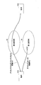
- FIG. 1 is an overall configuration diagram of a communication system according to an embodiment of the present invention. It is a sequence diagram for demonstrating the example of a basic procedure of ICE. It is a sequence diagram for demonstrating the operation example in a 1st Example. It is a sequence diagram for demonstrating the operation example in a 2nd Example.
- Example of P2P connection check (example when connection cannot be made via the first communication network) It is a figure for demonstrating another use case. It is a figure for demonstrating the example which installs a STUN server only in a specific communication network. It is a figure which shows the structure which equips a 1st communication network and a 2nd communication network with a signaling server.
- 2 is a configuration diagram of a terminal 40.
- FIG. 2 is a configuration diagram of a signaling server 30.
- FIG. 2 is a configuration diagram of a STUN server 11.
- IP address In the P2P communication described in the present embodiment, a pair of an IP address and a port number is used for specifying a communication destination or the like.
- a pair of an IP address and a port number is referred to as an “address”. I will call it. This may be referred to as a “transport address”.
- IP address it is described as an IP address, an IPv4 address, an IPv6 address, or the like.
- FIG. 1 is an overall configuration diagram of a communication system according to an embodiment of the present invention.
- the communication system in the present embodiment includes a first communication network 10 and a second communication network 20.
- the first communication network 10 and the second communication network 20 have different IP addresses used for packet routing.
- IP address used for packet routing.
- IPv4 address used for example, when one uses “IPv4 address” and the other uses “IPv6 address”, one uses a specific address band of “IP address”.
- IP address When the other uses another address band of the same type of “IP address”.
- One is an “IP address” used in a global network such as the Internet, and the other is an “IP address” used in a closed network such as an NW, for example, VPN, physically or logically separated from the global network.
- NW for example, VPN, physically or logically separated from the global network.
- NW for example, VPN
- the first communication network 10 and the second communication network 20 are not limited to specific types of networks, in the present embodiment, as an example, the first communication network 10 is an access network (example: NGN network). 2 It is assumed that the communication network 20 is the Internet connected to an access network. However, there are other use cases, which will be described later. In FIG. 1, for convenience, the first communication network 10 and the second communication network 20 are illustrated separately. The number of communication networks is not limited to two, and three or more communication networks may be provided.
- the communication system includes a terminal 40A and a terminal 40B, which are terminals that perform P2P communication.
- each terminal is a browser or a terminal such as a general PC or smartphone equipped with software having a WebRTC communication function equivalent to a browser, a smart phone, a mobile phone, or an IoT / M2M device such as a sensor / actuator.
- this is only an example, and data communication may be performed using P2P communication.
- these video, data, audio, and the like are collectively referred to as “media”.
- a NAT device 50A is installed at a base where the terminal 40A is provided, and a NAT device 50B is installed at a base where the terminal 40B is provided.
- the NAT devices 50A / 50B basically have addresses (referred to as internal addresses) allocated locally in the terminals 40A / 40B and addresses used on the first communication network 10 / second communication network 20 side ( It is a device having a function of converting between external addresses). Note that the NAT device 50A / 50B is not necessarily provided, and the NAT device 50A / 50B may not be provided. Even when the first communication network 10 / second communication network 20 is a closed network, an address used on the first communication network 10 / second communication network 20 side is referred to as an external address.
- the communication system 30 includes a signaling server 30.
- the signaling server 30 is a device that relays control signals between the terminal 40A and the terminal 40B in order for the terminal 40A and the terminal 40B to establish a communication path (channel) for P2P communication.
- the signaling server 30 collects the information between the terminal 40A and the terminal 40B by each terminal. Exchange of the address candidates that have been made.
- Each of the terminal 40A and the terminal 40B registers with the signaling server 30 and communicates with the signaling server 30.
- the signaling server 30 may be installed anywhere.
- the signaling server 30 may be installed in the first communication network 10, may be installed in the second communication network 20, or may be installed in another network.
- the signaling server 30 may be referred to as a “communication control device”.
- the first communication network 10 is provided with a STUN server 11, and the second communication network 20 is provided with a STUN server 21.
- the STUN server 11 and the STUN server 21 have the same function as the STUN server.
- the STUN server 11 is assigned the address of the first communication network 10
- the STUN server 21 is assigned the address of the second communication network 20.
- the STUN server may be referred to as an “address notification device”.
- Each network may be provided with a plurality of STUN servers.
- the configuration having the STUN server 11 and the STUN server 21 may be referred to as a “communication system”.
- Each STUN server is a server having the STUN function described in Non-Patent Document 1, for example.
- a binding request address request
- the transmission source address is an external address after NAT conversion, for example.
- the terminal can know its own external address, and by notifying this to the communication partner, the communication partner can know the destination address to the terminal.
- the host address assigned to the terminal itself may be included in the binding response and returned.
- the address included in the binding response and returned to the terminal is called “ReflexiveflexTransport Address”.
- STUN is one of the technologies that can be used when NAT traversal is performed.
- TURN Traversal Using Relays around NAT.
- TURN is a technique in which a TURN server for relaying media packets is arranged in a communication network, and communication between terminals is enabled via the TURN server.
- each terminal in the present embodiment uses a protocol called ICE (Interactive Connectivity Establishment) described in Non-Patent Document 2 to determine an address to be used for P2P communication.
- ICE Interactive Connectivity Establishment
- each terminal collects addresses that can be used by STUN, TURN, etc., exchanges the collected addresses between terminals, performs a connection check (hole punching) with each other, and among the addresses that can be communicated Select the highest priority address for communication.
- the priority of selection is the highest in its own address (that is, when local communication not via the NAT device is performed), and then communicates via the external address notified by the STUN server and then via the TURN server. Address.
- TURN is not considered for convenience.
- the above-mentioned terminal address type (Type) is called “host”, and the STUN address type (Type) is called “server reflexive”. A part of “server reflexive” may be omitted and described as “srflx”.
- Example of basic procedure With reference to FIG. 2, an example of a basic procedure of ICE executed between terminal 40A and terminal 40B in the present embodiment will be described. This procedure is an example. Instead of the procedure shown in FIG. 2, for example, a procedure may be used in which the acquired candidate is immediately sent to the partner and the connection check is immediately performed. The procedure shown in FIG. 2 is executed via the signaling server 30, but the description of the signaling server 30 is omitted.
- step S101 the terminal 40A performs address collection. Specifically, the terminal 40A first acquires an address assigned to itself. This address is described as “address A” in the meaning of the host address on the terminal 40A side. Hereinafter, the same description method is used.
- address A the address on the first communication network 10 side
- second address the address on the second communication network 20 side
- the address of the STUN server 11 and the address of the STUN server 21 are set (stored) in advance, and the terminal 40A transmits the binding request to the STUN server 11 and receives the binding response, thereby receiving the first response.
- the address (srflx) A is acquired, the binding request is transmitted to the STUN server 21, and the binding response is received, thereby acquiring the second address (srflx) A.
- the above example is an example of a method for sending a binding request by directly specifying the STUN server address (IP address).
- IP address STUN server address
- the destination STUN server is specified by FQDN.
- a method in which the IP address is resolved by the DNS server may be used.
- the terminal 40A acquires the address (host) A, the first address (srflx) A, and the second address (srflx) A.
- the address of the port indicated by C corresponds to the address (host) A
- the address of the port indicated by D corresponds to the second address (srflx) A
- the address of the port indicated by E is This corresponds to the first address (srflx) A.
- An address (host) A that is a host address may exist for each of the first communication network 10 and the second communication network 20. That is, the first address (host) A and the second address (host) A may be acquired as the host addresses. In this example, a case where one address (host) A is acquired as the host address is shown as an example.
- the terminal 40A calculates a score corresponding to the priority (Priority) of each collected address.
- a score calculation method the method described in Chapter 4.1.2 of Non-Patent Document 2 can be used. Specifically, a score is calculated from a host preference value (eg, host: 128, srflx: 100) according to the type (host, srflx, etc.) and a local preference value according to the address family (IPv4, IPv6). calculate.
- the score calculation method is not limited to the method described in Chapter 4.1.2 of Non-Patent Document 2.
- Non-Patent Document 2 recommends that IPv6 be higher than IPv4, and this embodiment follows this recommendation.
- step S102 the terminal 40A transmits the addresses (referred to as address candidates) collected in step S101 to the terminal 40B together with the calculated score.
- addresses referred to as address candidates
- SDP Session Description Protocol
- step S102 the terminal 40A transmits “address (host) A and score, first address (srflx) A and score, second address (srflx) A and score” to the terminal 40B as address candidates. To do.
- step S103 the terminal 40B that has received the SDP offer including the address candidate receives the address (host) B, the first address (srflx) B, and the second address in the same manner as the address collection and score calculation on the terminal 40A side.
- the address (srflx) B is acquired, and each score is calculated.
- step S104 the terminal 40B transmits "address (host) B and score, first address (srflx) B and score, second address (srflx) B and score" to the terminal 40A as an SDP answer.
- each of the terminal 40A and the terminal 40B has its own address candidate and a partner address candidate.
- Each of the terminal 40A and the terminal 40B creates a combination (set) of address pairs in which one address and one address of the other party are paired, calculates a score for each address pair, and arranges them in order of priority ( This is called a checklist).
- the scoring can use the method described in 5.7.2 of Non-Patent Document 2. In this method, basically, if the score of each address constituting a pair is high, a high score can be obtained. However, scoring by the method described in 5.7.2 of Non-Patent Document 2 is only an example, and scoring may be performed by other methods.
- each of the terminal 40A and the terminal 40B performs a connection check for each address pair.
- the connection check hole punching using a STUN binding request is executed. For example, when a binding request is transmitted from the terminal 40A to the destination address of the terminal 40B in a certain address pair (referred to as address B) and a binding response is received, the address (reflexive address) included in the binding response (this Is called address A). If there is an address pair in the check list that matches the pair of address A and address B, the connection check has succeeded for the address pair.
- the connection check may be performed only from the terminal 40A (controlling agent).
- the connection check is performed by the method as described above.
- the terminal 40A (controlling agent) uses the address pair having the highest priority among the address pairs for which the connection check is successful for media transmission.
- the address pair is determined and notified to the terminal 40B (controlled agent). If the terminal 40B can use the address pair (eg, if it is an address pair included in an address pair for which a connection check from the terminal 40B has been successful), the terminal 40B may determine to use the address pair. . Further, the terminal 40B may execute the same processing as that of the terminal 40A, and the terminal 40B may determine an address pair for transmission from the terminal 40B. Thereafter, P2P communication using the determined address pair is performed (step S106). For example, the terminal 40A transmits the medium to the destination address of the determined address pair, and the terminal 40B transmits the medium to the destination address of the determined address pair.
- address pair used for transmission from the terminal 40A and the address pair used for transmission from the terminal 40B may be the same or different.
- the address determination method as described above is merely an example, and the address may be determined by another method.
- the 1st Example and the 2nd Example which are more specific operation examples are described.
- the first communication network 10 is a network (for example, NGN network) that performs packet routing using an IPv6 address, and the second communication network 20 uses an IPv4 address for packet routing.
- Network for example, the Internet.
- step S201 the terminal 40A performs address collection.
- the terminal 40A is assigned a private (local) IPv4 address and a private IPv6 address from the NAT device 50A, and the IPv4 and IPv6 addresses are acquired as the host addresses. To do. These are described as “IPv4 (host) A” and “IPv6 (host) A”. Further, the terminal 40A acquires IPv4 (srflx) A and IPv6 (srflx) A by transmitting a binding request to each of the STUN server 21 and the STUN server 11 and receiving a binding response from each of them.
- the terminal 40A calculates the score of each collected address.
- the scores are calculated in the order of the size shown in “IPv6 (host) A> IPv4 (host) A> IPv6 (srflx) A> IPv4 (srflx) A”.
- step S202 the terminal 40A transmits the address candidates collected in step S201 to the terminal 40B together with the calculated score. Specifically, in step S202, the terminal 40A receives a message including “IPv6 (host) A and score, IPv4 (host) A and score, IPv6 (srflx) A and score, IPv4 (srflx) A and score”. Transmit to terminal 40B.
- step S203 address collection is performed in the terminal 40B.
- step S204 the terminal 40B determines that “IPv6 (host) B and score, IPv4 (host) B and score, IPv6 (srflx) B and score, IPv4 (srflx)”.
- a message including “B and score” is transmitted to the terminal 40A.
- each of the terminal 40A and the terminal 40B has its own address candidate and a partner address candidate.
- Each of the terminal 40A and the terminal 40B creates a set of address pairs in which one address and one address of the other party are paired, calculates a score for each address pair, arranges them in order of priority, To do.
- a connection check is performed in step S205.
- the terminal 40A it is assumed that the connection check is successful in both the IPv6 (srflx) A and IPv6 (srflx) B pair and the IPv4 (srflx) A and IPv4 (srflx) B pair. If it is the same type (srflx), since IPv6 has a higher priority score, in step S206, the terminal 40A uses an IPv6 (srflx) A and IPv6 (srflx) B pair as an address pair for media transmission. Determine as. In the terminal 40B, an address pair is determined in the same procedure, and P2P communication is started in step S207. Alternatively, the address pair determined by the terminal 40A may be notified to the terminal 40B, and the terminal 40B may use the address pair.
- IPv4 is used on the Internet, and it is assumed that the P2P connection check with the host address is not successful between the terminals under the NAT device. Therefore, the case of the first embodiment is highly likely. It can be said that this is a case that can occur.
- the P2P communication between the terminal 40A and the terminal 40B is performed by adopting an unconventional configuration in which each of the first communication network 10 and the second communication network 20 includes a STUN server. , It can be executed by a route via the first communication network 10 (for example, NGN network).
- first communication network 10 for example, NGN network
- each of the first communication network 10 and the second communication network 20 includes a STUN server, even if P2P communication cannot be performed on one communication network, the other communication network There is also an effect that P2P communication can be performed by falling back.
- the first communication network 10 is a network (for example, an NGN network) that performs packet routing using an IPv6 address (this is referred to as a first IPv6 address).
- the network eg, the Internet
- performs packet routing using an IPv6 address in an address band different from the first IPv6 address referred to as a second IPv6 address.
- step S301 the terminal 40A performs address collection.
- the second IPv6 address used in the second communication network 20 is assigned to the terminal 40A, and the second IPv6 address is acquired as the host address. This is described as “second IPv6 (host) A”. Others will use the same format.
- the terminal 40A acquires the second IPv6 (srflx) A and the first IPv6 (srflx) A by transmitting a binding request to each of the STUN server 21 and the STUN server 11 and receiving a binding response from each of them.
- the NAT device 50A converts the source address for the packet to the first communication network 10 (2nd IPv6 ⁇ 1st IPv6 conversion), but transmits the packet to the second communication network 20. Does not translate the original address. Therefore, the second IPv6 (srflx) A is the same as the second IPv6 (host) A, and as a result, only the second IPv6 (host) A is acquired as the host address. In such a case, the STUN server 21 may return information indicating that the source address is the host address without returning the second IPv6 (srflx) A.
- the terminal 40A calculates the score of each collected address.
- the scores are calculated in the order of the size shown in “second IPv6 (host) A> first IPv6 (srflx) A”.
- second IPv6 (host) A is 200
- the score of the first IPv6 (srflx) A is 100.
- step S302 the terminal 40A transmits the address candidates collected in step S301 together with the calculated score. Specifically, in step S302, the terminal 40A transmits a message including “second IPv6 (host) A and score 200, first IPv6 (srflx) A and score 100” as address candidates.
- the signaling server 30 receives the above message and confirms the address candidate.
- the signaling server 30 detects the second IPv6 (host) A and the first IPv6 (srflx) A as address candidates, and detects that the magnitude relationship of the scores is “second IPv6 (host) A> first IPv6 (srflx) A”. To do.
- the signaling server 30 has an address score of the second communication network 20 smaller than the address score of the first communication network 10 so that P2P communication between terminals passes through the first communication network 10 (eg, NGN network) as much as possible. Thus, it has a function of converting the score. For example, the signaling server 30 converts the score of the second IPv6 (host) A from 200 to 100 and converts the score of the first IPv6 (srflx) A from 100 to 200 (step S303). Then, the signaling server 30 transfers the address candidates “second IPv6 (host) A and score 100, first IPv6 (srflx) A and score 200” with the converted score to the terminal 40B (step S304).
- the signaling server 30 converts the score of the second IPv6 (host) A from 200 to 100 and converts the score of the first IPv6 (srflx) A from 100 to 200 (step S303). Then, the signaling server 30 transfers the address candidates “second IPv6 (host) A and score 100
- the signaling server 30 may also transmit the address candidates “second IPv6 (host) A and score 100, first IPv6 (srflx) A and score 200” to which the converted score is attached to the terminal 40A.
- the terminal 40A can use the score after score conversion for the source address (own address) in scoring the address pair.
- the score conversion is performed so that the score conversion functions effectively without using the score after the score conversion for the source address.
- step S307 by converting the score of the destination address (first IPv6 (srflx) B) to a sufficiently large value, the terminal 40A calculates scoring with a pair of the destination address and the source address.
- a pair including the first IPv6 (srflx) B as a transmission destination address is always set to have the highest score.
- step S305 address collection is performed in the terminal 40B, and in step S306, the terminal 40B transmits a message including “second IPv6 (host) B and score 200, first IPv6 (srflx) B and score 100” as address candidates. To do.
- step S307 the signaling server 30 performs score conversion in the same manner as in step S303, and the address candidates “second IPv6 (host) B and score 100, first IPv6 (srflx) B and score 200” to which the converted score is attached are obtained. Is transferred to the terminal 40A (step S308).
- the signaling server 30 may also transmit the address candidates “second IPv6 (host) B and score 100, first IPv6 (srflx) B and score 200” to which the converted score is attached to the terminal 40B.
- the terminal 40B can use the score after score conversion for the source address (own address) in scoring the address pair.
- the score conversion is performed so that the score conversion functions effectively without using the score after the score conversion for the source address.
- the terminal 40B calculates scoring with a pair of the destination address and the source address.
- a pair including the first IPv6 (srflx) A as a transmission destination address is always set to have the highest score.
- each of the terminal 40A and the terminal 40B has its own address candidate and a partner address candidate.
- Each of the terminal 40A and the terminal 40B creates a set of address pairs in which one address and one address of the other party are paired, calculates a score for each address pair, arranges them in order of priority, To do.
- a connection check is performed in step S309.
- the connection check is successful in both the first IPv6 (srflx) A and first IPv6 (srflx) B pair and the second IPv6 (host) A and second IPv6 (host) B pair.
- the pair of the first IPv6 (srflx) A and the first IPv6 (srflx) B is a pair of the second IPv6 (host) A and the second IPv6 (host) B.
- step S310 the terminal 40A determines the pair of the first IPv6 (srflx) A and the first IPv6 (srflx) B as an address pair for media transmission.
- an address pair is determined in the same procedure, and P2P communication is started in step S311.
- the address pair determined by the terminal 40A may be notified to the terminal 40B, and the terminal 40B may use the address pair.
- the score conversion method described above is merely an example.
- a conversion method may be used in which the score of one address corresponding to the network through which P2P communication is desired is increased (for example, the highest priority score is set).
- P2P communication between the terminal 40A and the terminal 40B is performed on a route via the first communication network 10 (eg, NGN network). Is possible.
- the first communication network 10 eg, NGN network
- the signaling server 30 may perform address conversion so that the score of the address on the second communication network 20 side becomes high.
- the setting in the signaling server 30 is changed to What is necessary is just to change so that address conversion may be performed so that the score of the address on the 1-communication network 10 side becomes high.
- the score conversion reference information stored in the data storage unit 33 of the signaling server 30 to be described later is replaced with information indicating that the address conversion is performed so that the address score on the first communication network 10 side becomes high. That's fine.
- the signaling server 30 having the function of the second embodiment may be used.
- the signaling server 30 confirms that the score of the address of the first communication network 10 is higher, determines that the score conversion is unnecessary, and performs the score conversion.
- the address candidate is transferred without any problem.
- FIG. 1 The configuration of FIG. 1 described so far corresponds to a case where the first communication network 10 is an access network and the second communication network 20 is the Internet as an example.
- both the terminal 40A and the terminal 40B belong to the same access network (first communication network 10).
- the technique according to the present embodiment can be applied not only when the terminal 40A and the terminal 40B belong to the same access network as described above.
- the present invention can also be applied when both terminals belong to different access networks and are connected to the Internet through these access networks.
- the address information acquired by both terminals from the STUN servers in the respective access networks is exchanged using the signaling server 30, and a P2P connection check is performed. For example, if the access networks are interconnected, P2P communication via the access network is executed. On the other hand, when there is no mutual connection or the like, a P2P connection check is performed using another address (for example, an Internet address). If communication is possible, a connection via the network of the address is established. That is, as a fallback destination, communication via a connectable network (for example, the Internet) can be automatically established, and the service availability is increased.
- a connectable network for example, the Internet
- Example of P2P connection check (example when connection cannot be made with the first communication network 10)) For example, even if the address score of the first communication network 10 is higher than the score of the address of the second communication network 20 as in the first embodiment, the connection check in the first communication network 10 must succeed. For example, P2P communication in the first communication network 10 cannot be performed. For example, as shown in FIG. 5, the connection via the first communication network 10 may be refused. As an example of such a case, for example, there is a case where P2P communication via the first communication network 10 is not permitted as a policy of the first communication network 10.
- the connection is established. That is, according to the present embodiment, communication via the second communication network 20 (for example, the Internet) can be automatically established as a fallback destination, and the service availability is increased.
- the second communication network 20 for example, the Internet
- the first communication network 10 is an access network such as an NGN network and the second communication network 20 is the Internet.
- the first communication network 10 may be a closed network such as a VPN
- the second communication network 20 may be the Internet.
- An example of VPN is IP-VPN using MPLS technology.
- both the first communication network 10 and the second communication network 20 may be IPv4, both may be IPv6, or one may be IPv4 and the other may be IPv6. .
- the signaling server 30 has an address so that the address score on the second communication network 20 side becomes high. Conversion may be performed (score conversion in S303 and S307 in FIG. 4).
- the setting in the signaling server 30 is What is necessary is just to change so that address conversion may be performed so that the score of the address on the first communication network 10 side becomes high.
- the score conversion reference information stored in the data storage unit 33 of the signaling server 30 to be described later is replaced with information indicating that the address conversion is performed so that the address score on the first communication network 10 side becomes high. That's fine.
- the STUN server 11 may be provided only in the first communication network 10 (eg, access network).
- the P2P connection check between terminals is performed by the host address and the address that can be collected from the STUN server 11 in the first communication network 10.
- P2P communication using the host address cannot be performed. Therefore, in this case, unless P2P communication via the first communication network 10 is restricted, P2P communication using addresses that can be collected from the STUN server 11, that is, P2P communication via the first communication network 10 is performed.
- P2P communication via the first communication network 10 is restricted, if the IPv6 global Internet address is given to each terminal as the host address, the second communication by the fallback described above.
- P2P communication via the network 20 eg, the Internet
- the single installation place of the signaling server 30 is not limited, but the signaling server 30 may be provided in each network as shown in FIG. That is, in the example shown in FIG. 8, the first communication network 10 is provided with a signaling server 30-1, and the second communication network 20 is provided with a signaling server 30-2.
- the first communication network 10 may be an access network such as an NGN network, a closed network as described with reference to FIG. 6, or another network. Also good.
- the second communication network 20 is assumed to be the Internet, but may be a network other than the Internet.
- both the first communication network 10 and the second communication network 20 may be IPv4, both may be IPv6, or one may be IPv4 and the other may be IPv6. .
- Both the signaling server 30-1 and the signaling server 30-2 have the same functions as the signaling server 30 described so far. That is, if only the signaling server 30-1 of the signaling server 30-1 and the signaling server 30-2 is installed, the signaling server 30-1 is the same as that in the first and second embodiments. The same operation as the described signaling server 30 can be performed. If only the signaling server 30-2 of the signaling server 30-1 and the signaling server 30-2 is installed, the signaling server 30-2 is the same as that in the first embodiment and the second embodiment. The same operation as the described signaling server 30 can be performed.
- both the terminal 40A and the terminal 40B register with the signaling server 30-1 and the signaling server 30-2, and communicate with each other.
- the terminal 40A and the terminal 40B use the signaling server 30-1 to operate the sequence described with reference to FIG.
- the sequence server described with reference to FIG. 3 is executed using the signaling server 30-2.
- the address collection (S201, S203) on the terminal itself side may be performed for each of the signaling server 30-1 and the signaling server 30-2, or the signaling server 30-1 and the signaling server 30-2. However, it may be performed once.
- the sequence using the signaling server 30-1 is established between the terminal 40A and the terminal 40B.
- Two P2P communication connections (sessions) are generated, that is, the P2P communication connection and the P2P communication connection established between the terminal 40A and the terminal 40B by the sequence using the signaling server 30-2.
- the terminal 40A (or terminal 40B) disconnects one of two different P2P communication connections. For example, since the score of the address pair is expected to be the same between two different P2P communication connections, one of them is disconnected at random.
- the terminal 40A (and the terminal 40B) includes the address pair determined by the sequence using the signaling server 30-1 and the address pair determined by the sequence using the signaling server 30-2. It is also possible to make one P2P communication connection using the address pair with the higher score.
- the terminal 40A and the terminal 40B use the signaling server 30-1 to perform the operation of the sequence described with reference to FIG.
- the signaling server 30-2 is used to execute the operation of the sequence described with reference to FIG.
- the address collection (S301, S305) on the terminal itself side may be performed for each of the signaling server 30-1 and the signaling server 30-2, or the signaling server 30-1 and the signaling server 30-2. However, it may be performed once.
- the sequence using the signaling server 30-1 is established between the terminal 40A and the terminal 40B.
- Two P2P communication connections are generated, that is, a P2P communication connection and a P2P communication connection established between the terminal 40A and the terminal 40B by the sequence using the signaling server 30-2.
- the terminal 40A (or terminal 40B) disconnects one of two different P2P communication connections. For example, since the score of the address pair is expected to be the same between two different P2P communication connections, one of them is disconnected at random.
- the terminal 40A (or the terminal 40B), for example, has two different Disconnect the lower address pair score between P2P communication connections. Further, when two different P2P communication connections via different communication networks are established, one P2P communication connection may be disconnected based on the score, or a communication network to be disconnected is determined in advance, The P2P communication connection via the communication network may be disconnected.
- the terminal 40A (and the terminal 40B) includes the address pair determined by the sequence using the signaling server 30-1 and the address pair determined by the sequence using the signaling server 30-2. It is also possible to make one P2P communication connection using the address pair with the higher score.
- FIG. 9 shows a configuration example of the terminal 40 (A, B) that executes the processing described in the present embodiment. Since the terminal 40A and the terminal 40B have the same configuration, they are described as the terminal 40 (A, B). In the following description, the terminal 40 is described.
- the terminal 40 includes a control communication unit 41, a media communication unit 42, and a data storage unit 43.
- the control communication unit 41 transmits / receives control signals to / from the STUN servers 11 and 21 and the signaling servers 30, 30-1 and 30-2, and transmits media (video, audio, data, etc.).
- An address used in P2P communication is determined.
- the media communication unit 42 executes P2P communication by using the address determined by the control communication unit 41.
- the data storage unit 43 stores, for example, addresses of the STUN servers 11 and 21 to be accessed by the control communication unit 41, addresses of the signaling servers 30, 30-1, and 30-2, DNS server addresses, and the like.
- the control communication unit 41 uses the addresses of the STUN servers 11 and 21 and the addresses of the signaling servers 30, 30-1 and 30-2, and the STUN servers 11 and 21 and the signaling servers 30, 30-1 and 30-2 Communicate.
- the STUN servers 11 and 21 are designated by FQDN
- the user inputs the FQDN to the control communication unit 41.
- the FQDN is stored in the data storage unit 43, and the control communication unit 41 acquires the FQDN from the data storage unit 43. Then, the control communication unit 41 accesses the DNS server by using the DNS server address stored in the data storage unit 43 to perform address resolution and access the STUN servers 11 and 21.
- the terminal 40 according to the present embodiment can be realized, for example, by causing a computer to execute a program describing the processing contents described in the present embodiment.
- the functions of the terminal 40 can be realized by executing a program corresponding to the processing executed on the terminal 40 using hardware resources such as a CPU, memory, and hard disk built in the computer. It is.
- the above-mentioned program can be recorded on a computer-readable recording medium (portable memory or the like), stored, or distributed. It is also possible to provide the program through a network such as the Internet or electronic mail.
- the terminal 40 can be realized by a terminal having a browser or software having a WebRTC communication function corresponding to the browser.
- the terminal is, for example, a PC, a smartphone, a mobile phone, or an IoT / M2M device such as a sensor / actuator.
- the terminal 40 first acquires a program (Web application) from a server or the like provided in the first communication network 10, the second communication network 20, or other network, and the program is executed by the terminal 40.
- a program Web application
- FIG. 10 shows a configuration example of the signaling server 30 that executes the processing described in the present embodiment.
- the signaling servers 30-1 and 30-2 have the same configuration as the signaling server 30.
- the signaling server 30 includes a message relay unit 31, a score conversion unit 32, and a data storage unit 33.
- the message relay unit 31 relays messages including address candidates and the like exchanged between terminals.
- the score conversion unit 32 performs the score conversion described in the second embodiment. That is, score conversion is performed so that P2P communication between terminals passes through a predetermined communication network (for example, the first communication network 10). Note that converting the score so as to pass through the first communication network 10 is merely an example, and what kind of score conversion is performed can be changed by setting.
- network 1, network 2 and network 3, through which P2P communication can be routed if it is desired to route network 2 preferentially, address information of network 2 (example : Network 2 address band) and for the network 2 address, an instruction to perform score conversion is set so that the score is higher than the addresses of other networks.
- the score conversion unit 32 checks the address in the address candidates received from the terminal, and converts the score of the address when an address corresponding to the address band of the network 2 is detected. In addition, it is not necessary to convert, and if the score passes through the network 2, the conversion is not performed.
- the data storage unit 33 stores, for example, information related to the above settings (address information, score conversion rules, etc.). Since this information is information used as a reference for score conversion, it is referred to as score conversion reference information.
- the score conversion unit 32 can appropriately perform score conversion by referring to the score conversion reference information stored in the data storage unit 33.
- the functional unit corresponding to the data storage unit 33 may be provided as a separate server (external server) outside the signaling server 30. In this case, the signaling server 30 accesses the external server via the communication network. Then, the score conversion reference information is acquired from the external server, and the score conversion is performed based on the score conversion reference information.
- the signaling server 30 can be realized, for example, by causing one or a plurality of computers to execute a program describing the processing contents described in the present embodiment. That is, the function of the signaling server 30 is realized by executing a program corresponding to processing executed in the signaling server 30 using hardware resources such as a CPU, memory, and hard disk built in the computer. Is possible.
- the above-mentioned program can be recorded on a computer-readable recording medium (portable memory or the like), stored, or distributed. It is also possible to provide the program through a network such as the Internet or electronic mail.
- FIG. 11 shows a configuration diagram of the STUN server 11. Since the STUN server 21 has the same configuration, the STUN server 11 is shown in FIG. 11 as a representative. As shown in FIG. 11, the STUN server 11 includes an address acquisition unit 15 and an address notification unit 16.
- the address acquisition unit 15 receives the binding request transmitted from the terminal, and acquires the transmission source address of the binding request (for example, an address outside the NAT in the case of via NAT).
- the address notification unit 16 creates a binding response including the transmission source address acquired by the address acquisition unit 15 and transmits the binding response toward the transmission source address (that is, toward the transmission source terminal).
- the STUN server 11 can be realized by, for example, causing one or a plurality of computers to execute a program describing the processing contents described in the present embodiment. That is, the function of the STUN server 11 is realized by executing a program corresponding to the process executed by the STUN server 11 using hardware resources such as a CPU, memory, and hard disk built in the computer. Is possible.
- the above-mentioned program can be recorded on a computer-readable recording medium (portable memory or the like), stored, or distributed. It is also possible to provide the program through a network such as the Internet or electronic mail.
- FIG. 12 is a diagram illustrating a hardware configuration example of the device when the above-described devices (terminal 40, signaling server 30, STUN server 11) are realized by a computer.
- the device (terminal 40, signaling server 30, or STUN server 11) shown in FIG. 12 includes a drive device 150, an auxiliary storage device 152, a memory device 153, a CPU 154, an interface device 155, and a display connected to each other via a bus B.
- the program for realizing the processing in the apparatus is provided by a recording medium 151 such as a CD-ROM or a memory card.
- a recording medium 151 such as a CD-ROM or a memory card.
- the program is installed from the recording medium 151 into the auxiliary storage device 152 via the drive device 150.
- the program does not necessarily have to be installed from the recording medium 151, and may be downloaded from another computer via a network.
- the auxiliary storage device 152 stores the installed program and also stores necessary files and data.
- the memory device 153 reads the program from the auxiliary storage device 152 and stores it when there is an instruction to start the program.
- the CPU 154 (processor) implements functions related to the device according to a program stored in the memory device 153.
- the interface device 155 is used as an interface for connecting to a network.
- the display device 156 displays a GUI (Graphical User Interface) by a program.
- the input device 157 includes a keyboard and mouse, buttons, a touch panel, and the like, and is used to input various operation instructions.
- the communication system includes the first address notification device provided in the first communication network and the second address notification device provided in the second communication network.
- the 1-address notification device receives an address request from a terminal communicable with the first address notification device and the second address notification device, acquires a transmission source address from the address request, and a response including the transmission source address Means for transmitting to the terminal,
- the second address notification device comprises means for receiving an address request from the terminal, obtaining a transmission source address from the address request, and transmitting a response including the transmission source address to the terminal.
- a communication system is provided.
- the communication system may include a communication control device, and the communication control device includes, for example, a set of addresses including addresses notified from the first address notification device and the second address notification device to the terminal. , And receives the set of addresses from the terminal, and transmits the set of addresses to the communication partner terminal that is the communication partner of the terminal.
- the communication control device includes, for example, a set of addresses including addresses notified from the first address notification device and the second address notification device to the terminal. , And receives the set of addresses from the terminal, and transmits the set of addresses to the communication partner terminal that is the communication partner of the terminal.
- the communication control device has a score indicating a priority added to each address in the set of addresses so that communication between the terminal and the communication partner terminal is performed via a predetermined communication network. Of these, the score of at least one address may be converted. At this time, the communication control apparatus may acquire score conversion reference information from an external server and perform score conversion based on the score conversion reference information.
- the first communication network includes the first address notification device.
- An address notification device functioning as a first address notification device, which is a terminal capable of communicating with the first address notification device and the second address notification device, and transmits an address request to the second address notification device.
- An address notification device comprising an address notification means for transmission is provided.
- the communication used in the communication system including the communication control device, the first address notification device provided in the first communication network, and the second address notification device provided in the second communication network.
- a control device that receives a set of addresses from a terminal that can communicate with the first address notification device and the second address notification device, and transmits the set of addresses to a communication partner terminal that is a communication partner of the terminal.
- Relay means wherein the set of addresses is an address acquired from a response to an address request transmitted from the terminal to the first address notification device, and transmitted from the terminal to the second address notification device
- a communication control device including an address acquired from a response to a received address request.
- the communication control device has a score indicating a priority added to each address in the set of addresses so that communication between the terminal and the communication partner terminal is performed via a predetermined communication network.
- conversion means for converting the score of at least one address may be provided.
- control communication is performed between a communication control device, a communication system including a first address notification device provided in the first communication network, and a second address notification device provided in the second communication network.
- a terminal that transmits an address request to the first address notification device receives a response including the transmission source address of the address request from the first address notification device, and obtains a transmission source address from the response Means for transmitting an address request to the second address notification device, receiving a response including the source address of the address request from the second address notification device, and obtaining a source address from the response;
- a set of addresses including addresses acquired from the responses received from the first address notification device and the second address notification device is transmitted to the communication control device.
- the communication control device a set of address received from the terminal, the terminal and transmits to the communication terminal as a communication partner of the terminal is provided.
- the terminal receives a set of addresses acquired by the communication partner terminal from the communication control apparatus, and based on the set of addresses and the set of addresses acquired by the terminal, There may be provided means for determining an address pair to be used for the communication.
- communication including a first communication control device and a first address notification device provided in the first communication network, and a second communication control device and a second address notification device provided in the second communication network.
- the first communication control device and the second communication control device each receive a set of addresses from a terminal that can communicate with the first address notification device and the second address notification device, and Relay means for transmitting a set to a communication partner terminal serving as a communication partner of the terminal, wherein the set of addresses is an address obtained from a response to an address request transmitted from the terminal to the first address notification device; And an address acquired from a response to the address request transmitted from the terminal to the second address notification device.
- Shin system is provided.
- Each of the first communication control device and the second communication control device has each address in the set of addresses so that communication between the terminal and the communication partner terminal is performed via a predetermined communication network. It is good also as a conversion means to convert the score of at least 1 address among the scores which show the priority added to.
- the communication path used for the P2P communication between the terminals is appropriately selected by the technology according to the present embodiment described above. As a result, for example, the quality of P2P communication can be improved. Further, even when the communication path selected with the highest priority is not connectable, P2P communication can be performed by falling back to another communication path, so that the service availability can be increased.
- each communication network is provided with a signaling server, it is possible to avoid that P2P communication connection cannot be made at all when, for example, connection to the Internet cannot be performed.
Landscapes
- Engineering & Computer Science (AREA)
- Computer Networks & Wireless Communication (AREA)
- Signal Processing (AREA)
- Data Exchanges In Wide-Area Networks (AREA)
- Small-Scale Networks (AREA)
Abstract
第1通信網に備えられる第1アドレス通知装置と、第2通信網に備えられる第2アドレス通知装置とを含む通信システムにおいて、前記第1アドレス通知装置は、当該第1アドレス通知装置及び前記第2アドレス通知装置と通信可能な端末から、アドレス要求を受信し、当該アドレス要求から送信元アドレスを取得し、当該送信元アドレスを含む応答を前記端末に向けて送信する手段を備え、前記第2アドレス通知装置は、前記端末からアドレス要求を受信し、当該アドレス要求から送信元アドレスを取得し、当該送信元アドレスを含む応答を前記端末に向けて送信する手段を備える。
Description
本発明は、端末間でP2P通信を行うための技術に関連するものである。
近年、端末同士を接続して通信を行うP2P通信が普及してきている。P2P通信を実現するための技術としては種々の技術があるが、例えば、特別なアプリケーションを用いずに、端末のブラウザ間でP2P通信を実現するWebRTCがある。
WebRTC等を用いたP2P通信は、インターネットを経由して行われるのが一般的である。端末Aと端末Bとの間でインターネットを経由したP2P通信を行う場合、端末Aから送信されたパケットは、アクセス網を経由してISP(インターネットサービスプロバイダ)のインターネット接続用のルータに送られ、当該ルータからインターネットに送出される。そして、当該パケットは、端末B側のISPのルータに届き、アクセス網を経由して端末Bに届けられる。
RFC5389(STUN)
RFC5245(ICE)
上記のようなP2P通信において、例えば、端末Aの利用ISPと端末Bの利用ISPが異なる場合、端末Aと端末Bが地理的に近い位置(例:同じ都市内)にある場合であっても、端末Aと端末Bとの間のP2P通信は遠隔地にあるISP間接続点あるいはIXを経由して行われる可能性がある。
上記のように、従来のP2P通信に係る技術では、適切な通信経路が選択されない可能性があるという課題がある。なお、このようなP2P通信に係る課題は、アクセス網とインターネットを用いた通信に限った課題ではなく、他の網を用いた通信においても生じ得る課題である。
本発明は上記の点に鑑みてなされたものであり、端末間のP2P通信に使用される通信経路が適切に選択されるようにするための技術を提供することを目的とする。
本発明の実施の形態によれば、第1通信網に備えられる第1アドレス通知装置と、第2通信網に備えられる第2アドレス通知装置とを含む通信システムであって、
前記第1アドレス通知装置は、当該第1アドレス通知装置及び前記第2アドレス通知装置と通信可能な端末から、アドレス要求を受信し、当該アドレス要求から送信元アドレスを取得し、当該送信元アドレスを含む応答を前記端末に向けて送信する手段を備え、
前記第2アドレス通知装置は、前記端末からアドレス要求を受信し、当該アドレス要求から送信元アドレスを取得し、当該送信元アドレスを含む応答を前記端末に向けて送信する手段を備える
ことを特徴とする通信システムが提供される。
前記第1アドレス通知装置は、当該第1アドレス通知装置及び前記第2アドレス通知装置と通信可能な端末から、アドレス要求を受信し、当該アドレス要求から送信元アドレスを取得し、当該送信元アドレスを含む応答を前記端末に向けて送信する手段を備え、
前記第2アドレス通知装置は、前記端末からアドレス要求を受信し、当該アドレス要求から送信元アドレスを取得し、当該送信元アドレスを含む応答を前記端末に向けて送信する手段を備える
ことを特徴とする通信システムが提供される。
また、本発明の実施の形態によれば、第1通信網に備えられる第1アドレス通知装置と、第2通信網に備えられる第2アドレス通知装置とを含む通信システムにおいて、前記第1通信網に備えられる前記第1アドレス通知装置として機能するアドレス通知装置であって、
前記第1アドレス通知装置及び前記第2アドレス通知装置と通信可能な端末であって、前記第2アドレス通知装置にアドレス要求を送信するとともに、前記第1アドレス通知装置にアドレス要求を送信する端末から、当該アドレス要求を受信し、当該アドレス要求から送信元アドレスを取得する取得手段と、
前記送信元アドレスを含む応答を前記端末に向けて送信するアドレス通知手段と
を備えることを特徴とするアドレス通知装置が提供される。
前記第1アドレス通知装置及び前記第2アドレス通知装置と通信可能な端末であって、前記第2アドレス通知装置にアドレス要求を送信するとともに、前記第1アドレス通知装置にアドレス要求を送信する端末から、当該アドレス要求を受信し、当該アドレス要求から送信元アドレスを取得する取得手段と、
前記送信元アドレスを含む応答を前記端末に向けて送信するアドレス通知手段と
を備えることを特徴とするアドレス通知装置が提供される。
また、本発明の実施の形態によれば、通信制御装置と、第1通信網に備えられる第1アドレス通知装置と、第2通信網に備えられる第2アドレス通知装置とを含む通信システムにおいて使用される前記通信制御装置であって、
前記第1アドレス通知装置及び前記第2アドレス通知装置と通信可能な端末からアドレスの集合を受信し、当該アドレスの集合を当該端末の通信相手となる通信相手端末に送信する中継手段を備え、
前記アドレスの集合は、前記端末から前記第1アドレス通知装置に対して送信されたアドレス要求に対する応答から取得したアドレス、及び、前記端末から前記第2アドレス通知装置に対して送信されたアドレス要求に対する応答から取得したアドレスを含む
ことを特徴とする通信制御装置が提供される。
前記第1アドレス通知装置及び前記第2アドレス通知装置と通信可能な端末からアドレスの集合を受信し、当該アドレスの集合を当該端末の通信相手となる通信相手端末に送信する中継手段を備え、
前記アドレスの集合は、前記端末から前記第1アドレス通知装置に対して送信されたアドレス要求に対する応答から取得したアドレス、及び、前記端末から前記第2アドレス通知装置に対して送信されたアドレス要求に対する応答から取得したアドレスを含む
ことを特徴とする通信制御装置が提供される。
また、本発明の実施の形態によれば、通信制御装置と、第1通信網に備えられる第1アドレス通知装置と、第2通信網に備えられる第2アドレス通知装置とを含む通信システムとの間で制御通信を行う端末であって、
前記第1アドレス通知装置にアドレス要求を送信し、当該アドレス要求の送信元アドレスを含む応答を当該第1アドレス通知装置から受信し、当該応答から送信元アドレスを取得する手段と、
前記第2アドレス通知装置にアドレス要求を送信し、当該アドレス要求の送信元アドレスを含む応答を当該第2アドレス通知装置から受信し、当該応答から送信元アドレスを取得する手段と、
前記第1アドレス通知装置及び前記第2アドレス通知装置から受信した各応答から取得したアドレスを含むアドレスの集合を前記通信制御装置に送信する手段と、を備え、
前記通信制御装置は、前記端末から受信したアドレスの集合を、当該端末の通信相手となる通信相手端末に送信する
ことを特徴とする端末が提供される。
前記第1アドレス通知装置にアドレス要求を送信し、当該アドレス要求の送信元アドレスを含む応答を当該第1アドレス通知装置から受信し、当該応答から送信元アドレスを取得する手段と、
前記第2アドレス通知装置にアドレス要求を送信し、当該アドレス要求の送信元アドレスを含む応答を当該第2アドレス通知装置から受信し、当該応答から送信元アドレスを取得する手段と、
前記第1アドレス通知装置及び前記第2アドレス通知装置から受信した各応答から取得したアドレスを含むアドレスの集合を前記通信制御装置に送信する手段と、を備え、
前記通信制御装置は、前記端末から受信したアドレスの集合を、当該端末の通信相手となる通信相手端末に送信する
ことを特徴とする端末が提供される。
また、本発明の実施の形態によれば、第1通信網に備えられる第1アドレス通知装置と、第2通信網に備えられる第2アドレス通知装置とを含む通信システムにおいて実行される通信方法であって、
前記第1アドレス通知装置が、当該第1アドレス通知装置及び前記第2アドレス通知装置と通信可能な端末から、アドレス要求を受信し、当該アドレス要求から送信元アドレスを取得し、当該送信元アドレスを含む応答を前記端末に向けて送信し、
前記第2アドレス通知装置が、前記端末からアドレス要求を受信し、当該アドレス要求から送信元アドレスを取得し、当該送信元アドレスを含む応答を前記端末に向けて送信する
ことを特徴とする通信方法が提供される。
前記第1アドレス通知装置が、当該第1アドレス通知装置及び前記第2アドレス通知装置と通信可能な端末から、アドレス要求を受信し、当該アドレス要求から送信元アドレスを取得し、当該送信元アドレスを含む応答を前記端末に向けて送信し、
前記第2アドレス通知装置が、前記端末からアドレス要求を受信し、当該アドレス要求から送信元アドレスを取得し、当該送信元アドレスを含む応答を前記端末に向けて送信する
ことを特徴とする通信方法が提供される。
また、本発明の実施の形態によれば、第1通信網に備えられる第1通信制御装置及び第1アドレス通知装置と、第2通信網に備えられる第2通信制御装置及び第2アドレス通知装置とを含む通信システムであって、
前記第1通信制御装置と前記第2通信制御装置はそれぞれ、前記第1アドレス通知装置及び前記第2アドレス通知装置と通信可能な端末からアドレスの集合を受信し、当該アドレスの集合を当該端末の通信相手となる通信相手端末に送信する中継手段を備え、
前記アドレスの集合は、前記端末から前記第1アドレス通知装置に対して送信されたアドレス要求に対する応答から取得したアドレス、及び、前記端末から前記第2アドレス通知装置に対して送信されたアドレス要求に対する応答から取得したアドレスを含む
ことを特徴とする通信システムが提供される。
前記第1通信制御装置と前記第2通信制御装置はそれぞれ、前記第1アドレス通知装置及び前記第2アドレス通知装置と通信可能な端末からアドレスの集合を受信し、当該アドレスの集合を当該端末の通信相手となる通信相手端末に送信する中継手段を備え、
前記アドレスの集合は、前記端末から前記第1アドレス通知装置に対して送信されたアドレス要求に対する応答から取得したアドレス、及び、前記端末から前記第2アドレス通知装置に対して送信されたアドレス要求に対する応答から取得したアドレスを含む
ことを特徴とする通信システムが提供される。
本発明の実施の形態によれば、端末間のP2P通信に使用される通信経路が適切に選択されるようになる。
以下、図面を参照して本発明の実施の形態を説明する。なお、以下で説明する実施の形態は一例に過ぎず、本発明が適用される実施の形態は、以下の実施の形態に限られるわけではない。
本実施の形態で説明するP2P通信では、通信の宛先等の指定のために、IPアドレスとポート番号の組が用いられるが、以下では、便宜上、IPアドレスとポート番号の組を「アドレス」と呼ぶことにする。これを「トランスポートアドレス」と称してもよい。「IPアドレス」に言及する場合には、IPアドレス、IPv4アドレス、IPv6アドレス等と記述する。
(システム構成)
図1は、本発明の実施の形態に係る通信システムの全体構成図である。図1に示すように、本実施の形態における通信システムは、第1通信網10、第2通信網20を備える。第1通信網10と第2通信網20では、パケットのルーティングに使用されるIPアドレスが異なる。ここでの「IPアドレスが異なる」場合としては、例えば、一方が「IPv4アドレス」を使用し、他方が「IPv6アドレス」を使用する場合、一方が「IPアドレス」の特定のアドレス帯を使用し、他方が同じ種類の「IPアドレス」の別のアドレス帯を使用する場合、等がある。また、一方が、インターネット等のグローバルネットワークで使用される「IPアドレス」であり、他方が、物理的あるいは論理的にグローバルネットワークから分離されたNW、例えばVPNなどの閉域網で使用される「IPアドレス」である場合も「IPアドレスが異なる」場合に相当する。
図1は、本発明の実施の形態に係る通信システムの全体構成図である。図1に示すように、本実施の形態における通信システムは、第1通信網10、第2通信網20を備える。第1通信網10と第2通信網20では、パケットのルーティングに使用されるIPアドレスが異なる。ここでの「IPアドレスが異なる」場合としては、例えば、一方が「IPv4アドレス」を使用し、他方が「IPv6アドレス」を使用する場合、一方が「IPアドレス」の特定のアドレス帯を使用し、他方が同じ種類の「IPアドレス」の別のアドレス帯を使用する場合、等がある。また、一方が、インターネット等のグローバルネットワークで使用される「IPアドレス」であり、他方が、物理的あるいは論理的にグローバルネットワークから分離されたNW、例えばVPNなどの閉域網で使用される「IPアドレス」である場合も「IPアドレスが異なる」場合に相当する。
第1通信網10と第2通信網20はそれぞれ特定の種類の網に限定されないが、本実施の形態では、一例として、第1通信網10はアクセス網(例:NGN網)であり、第2通信網20は、アクセス網に接続されたインターネットであることを想定している。ただし、他のユースケースもあり、それについては後述する。なお、図1では、便宜上、第1通信網10と第2通信網20を分離して描いている。また、通信網の数は2つに限られず、3つ以上の通信網が備えられていてもよい。
図1に示すように、本通信システムには、P2P通信を行う端末である端末40Aと端末40Bが備えられている。本実施の形態では、各端末はブラウザあるいはブラウザに相当するWebRTC通信機能を持つソフトウェアを備える一般的なPCあるいはスマートフォン、携帯電話機、またはセンサ・アクチュエータ等のIoT・M2Mデバイス等の端末であり、WebRTCを用いてP2P通信によりビデオ通話等を行うことを想定しているが、これは一例に過ぎず、P2P通信によりデータの通信を行ってもよい。また、P2P通信により音声通話を行ってもよい。本明細書の説明においては、これらビデオ、データ、音声等を総称して「メディア」と呼ぶ。
また、端末40Aが備えられる拠点にはNAT装置50Aが設置され、端末40Bが備えられる拠点にはNAT装置50Bが設置されている。NAT装置50A/50Bは、基本的に、端末40A/40Bにおいてローカルに割り当てられているアドレス(内部アドレスと呼ぶ)と、第1通信網10/第2通信網20の側で使用されるアドレス(外部アドレスと呼ぶ)とを相互に変換する機能を備える装置である。なお、NAT装置50A/50Bを備えることは必須ではなく、NAT装置50A/50Bを備えないこととしてもよい。なお、第1通信網10/第2通信網20が閉域網である場合でも、第1通信網10/第2通信網20の側で使用されるアドレスを外部アドレスと呼ぶ。
図1に示すように、本通信システム30には、シグナリングサーバ30が備えられる。シグナリングサーバ30は、端末40Aと端末40Bが、P2P通信のための通信経路(チャネル)を確立するために、端末40Aと端末40Bとの間の制御信号の中継を行う装置である。詳細は後述するが、より具体的には、端末40Aと端末40BがP2P通信のためのアドレスペアを決定する際に、シグナリングサーバ30は、端末40Aと端末40Bとの間で、各端末により収集されたアドレス候補の交換等を行う。端末40Aと端末40Bはそれぞれ、シグナリングサーバ30に登録を行って、シグナリングサーバ30と通信を行う。
端末40Aと端末40Bとの間のシグナリングを実行できるのであれば、シグナリングサーバ30はどこに設置されていてもよい。例えば、シグナリングサーバ30は、第1通信網10に設置されてもよいし、第2通信網20に設置されてもよいし、その他の網に設置されてもよい。なお、シグナリングサーバ30を「通信制御装置」と称してもよい。
更に、図1に示すように、第1通信網10にSTUNサーバ11が備えられ、第2通信網20にSTUNサーバ21が備えられる。STUNサーバ11とSTUNサーバ21は、STUNサーバとしての機能は同じである。ただし、STUNサーバ11には第1通信網10のアドレスが割り当てられ、STUNサーバ21には第2通信網20のアドレスが割り当てられている。なお、STUNサーバを「アドレス通知装置」と称してもよい。また、各網に複数のSTUNサーバが備えられていてもよい。また、STUNサーバ11とSTUNサーバ21とを有する構成を「通信システム」と称してもよい。
各STUNサーバは、例えば非特許文献1に記載されたSTUNの機能を有するサーバである。基本的な機能として、各STUNサーバは、端末から送信されたバインディングリクエスト(アドレス要求)を受信したら、当該リスエストのパケットから送信元アドレスを取得し、当該送信元アドレスをバインディングレスポンス(アドレス応答)に含め、当該バインディングレスポンスを送信元アドレス宛に送信する機能を備える。本実施の形態では、上記の送信元アドレスは、例えばNAT変換後の外部アドレスである。これにより、端末は、自身の外部アドレスを知ることができ、これを通信相手に通知することで、通信相手は、当該端末への宛先アドレスを知ることができる。なお、NAT装置が存在しない場合、端末自身に割り当てられたホストアドレスがバインディングレスポンスに含められて、返されることとしてもよい。
バインディングレスポンスに含められて端末に返されるアドレスは「Reflexive Transport Address」と呼ばれる。
STUNは、NAT越えを行う際に使用できる技術の1つであり、その他の技術として、例えば、TURN(Traversal Using Relays around NAT)がある。TURNは、メディアのパケットを中継するためのTURNサーバを通信網内に配置し、TURNサーバを経由して端末間の通信を可能とする技術である。
(ICEについて)
端末40Aと端末40Bとの間でP2P通信を行うためには、両端末はお互いのアドレスを知る必要がある。そこで、本実施の形態における各端末は、非特許文献2に記載されているICE(Interactive Connectivity Establishment)と呼ばれるプロトコルを使用して、P2P通信に使用するアドレスを決定する。
端末40Aと端末40Bとの間でP2P通信を行うためには、両端末はお互いのアドレスを知る必要がある。そこで、本実施の形態における各端末は、非特許文献2に記載されているICE(Interactive Connectivity Establishment)と呼ばれるプロトコルを使用して、P2P通信に使用するアドレスを決定する。
ICEでは、各端末が、STUNやTURN等で利用可能なアドレスを収集し、端末間で、収集されたアドレスを交換して、お互いに接続チェック(ホールパンチング)を行い、通信可能なアドレスのうち最も優先度の高いアドレスを選択して通信を行う。選択の優先順位は、例えば、自身のアドレスが最も高く(つまりNAT装置を介さないローカル通信を行う場合)、次にSTUNサーバにより通知された外部アドレス、その次にTURNサーバを経由して通信するためのアドレスとなる。より具体的な例については後述する。なお、本実施の形態では、便宜上、TURNを考慮しないものとする。
上記の端末自身のアドレスの種別(Type)を「host」と呼び、STUNのアドレスの種別(Type)を、「server reflexive」と呼ぶ。「server reflexive」は、一部を省略して、「srflx」と記述してもよい。
(基本的な手順例)
図2を参照して、本実施の形態における、端末40Aと端末40Bとの間で実行されるICEの基本的な手順例を説明する。なお、この手順は一例である。図2に示す手順に代えて、例えば、取得した候補をすぐに相手に送り、すぐに接続チェックを行うような手順を用いてもよい。また、図2に示す手順は、シグナリングサーバ30を介して実行されるが、シグナリングサーバ30の記載は省略している。
図2を参照して、本実施の形態における、端末40Aと端末40Bとの間で実行されるICEの基本的な手順例を説明する。なお、この手順は一例である。図2に示す手順に代えて、例えば、取得した候補をすぐに相手に送り、すぐに接続チェックを行うような手順を用いてもよい。また、図2に示す手順は、シグナリングサーバ30を介して実行されるが、シグナリングサーバ30の記載は省略している。
ステップS101において、端末40Aは、アドレス収集を行う。具体的には、端末40Aは、まず、自身に割り当てられているアドレスを取得する。このアドレスを、端末40A側のhostのアドレスという意味で、「アドレス(host)A」と記述する。以下、同様の記述方式を用いる。また、以下では、第1通信網10側のアドレスを「第1アドレス」、第2通信網20側のアドレスを「第2アドレス」と呼ぶことにする。
端末40Aには、STUNサーバ11のアドレスとSTUNサーバ21のアドレスが予め設定(格納)されており、端末40Aは、STUNサーバ11にバインディングリクエストを送信し、バインディングレスポンスを受信することで、第1アドレス(srflx)Aを取得し、STUNサーバ21にバインディングリクエストを送信し、バインディングレスポンスを受信することで、第2アドレス(srflx)Aを取得する。
上記の例は、STUNサーバのアドレス(IPアドレス)を直接指定することでバインディングリクエストを送信する方法の例であるが、このような方法の他、例えば、宛先とするSTUNサーバをFQDNで指定して、IPアドレスをDNSサーバによって解決してもらう方法を使用してもよい。
上記のようにして、端末40Aは、アドレス(host)A、第1アドレス(srflx)A、及び、第2アドレス(srflx)Aを取得する。図1において、例えば、Cで示されるポートのアドレスがアドレス(host)Aに相当し、Dで示されるポートのアドレスが第2アドレス(srflx)Aに相当し、Eで示されるポートのアドレスが第1アドレス(srflx)Aに相当する。なお、hostのアドレスであるアドレス(host)Aは、第1通信網10と第2通信網20のそれぞれに対して存在しても良い。つまり、hostのアドレスとして、第1アドレス(host)Aと第2アドレス(host)Aが取得されてもよい。本例では、hostのアドレスとして1つのアドレス(host)Aが取得された場合を例として示している。
次に、端末40Aは、収集した各アドレスの優先度(Priority)に相当するスコアを算出する。スコアの算出方法は、非特許文献2の4.1.2章に記載されている方法を使用することができる。具体的には、種別(host、srflx等)に応じたhost preferenceの値(例:host:128、srflx:100)と、アドレスファミリ(IPv4、IPv6)に応じたLocal Preferenceの値などからスコアを算出する。ただし、スコアの算出方法は、非特許文献2の4.1.2章に記載されている方法に限られるわけではない。Local preferenceの値に関し、非特許文献2において、IPv6のほうがIPv4よりも高い値とすることが推奨されており、本実施の形態では、この推奨に従う。
次に、ステップS102において、端末40Aは、ステップS101で収集されたアドレス(アドレス候補と呼ぶ)を、算出したスコアとともに端末40Bに送信する。ここでは、例として、SDP(Session Description Protocol)オファーのメッセージを使用する。
具体的には、ステップS102において、端末40Aは、「アドレス(host)Aとスコア、第1アドレス(srflx)Aとスコア、第2アドレス(srflx)Aとスコア」をアドレス候補として端末40Bに送信する。
アドレス候補を含むSDPオファーを受信した端末40Bは、ステップS103において、端末40A側でのアドレス収集及びスコア算出と同様にして、アドレス(host)B、第1アドレス(srflx)B、及び、第2アドレス(srflx)Bを取得して、それぞれのスコアを算出する。
そして、ステップS104において、端末40Bは、SDPアンサーとして、「アドレス(host)Bとスコア、第1アドレス(srflx)Bとスコア、第2アドレス(srflx)Bとスコア」を端末40Aに送信する。
これにより、端末40Aと端末40Bはそれぞれ、自身のアドレス候補と、相手のアドレス候補を持つ。そして、端末40Aと端末40Bはそれぞれ、自身のアドレス1つと相手のアドレス1つをペアにしたアドレスペアの組み合わせ(集合)を作成するとともに、アドレスペア毎のスコアを算出し、優先度順に並べる(これをチェックリストと呼ぶことにする)。ここでのスコアリングは、非特許文献2の5.7.2に記載された方法を用いることができる。この方法では、基本的に、ペアを構成する各アドレスのスコアが高ければ、高いスコアが得られる。ただし、非特許文献2の5.7.2に記載された方法でスコアリングを行うことは一例に過ぎず、他の方法でスコアリングを行ってもよい。
ステップS105では、端末40Aと端末40Bはそれぞれ、アドレスペア毎に接続チェックを行う。接続チェックでは、STUNのバインディングリクエストを使用したホールパンチングが実行される。例えば、端末40Aから、あるアドレスペアにおける端末40Bの宛先アドレス(これをアドレスBと呼ぶ)宛にバインディングリクエストを送信し、バインディングレスポンスを受信した場合、バインディングレスポンスに含まれるアドレス(reflexive address)(これをアドレスAと呼ぶ)を取得する。そして、アドレスAとアドレスBのペアと一致する、チェックリストの中のアドレスペアがあれば、当該アドレスペアは接続チェックが成功したことになる。なお、接続チェックは、端末40A(controlling agent)からのみ行うこととしてもよい。
上記のような方法で接続チェックを行い、例えば、端末40A(controlling agent)が、接続チェックが成功したアドレスペアのうち、最も優先度の高いアドレスペアを、メディアの送信のために使用することを決定して、当該アドレスペアを端末40B(controlled agent)に通知する。端末40Bは、当該アドレスペアを使用できる場合(例:端末40Bからの接続チェックが成功したアドレスペアに含まれるアドレスペアである場合)、端末40Bは当該アドレスペアを使用することを決定してよい。また、端末40Bにおいても端末40Aと同様の処理を実行し、端末40Bが端末40Bからの送信のためのアドレスペアを決定してもよい。その後、決定したアドレスペアを使用したP2P通信が実行される(ステップS106)。例えば、端末40Aは決定したアドレスペアの送信先のアドレスにメディアを送信し、端末40Bは決定したアドレスペアの送信先のアドレスにメディアを送信する。
なお、端末40Aからの送信に用いられるアドレスペアと、端末40Bからの送信に用いられるアドレスペアは、同じでもよいし、異なっていてもよい。
なお、上記のようなアドレスの決定方法は一例に過ぎず、他の方法でアドレスを決定してもよい。以下では、より具体的な動作例である第1の実施例と第2の実施例を説明する。
(第1の実施例)
第1の実施例において、端末40Aと端末40Bとの間で実行される動作を図3を参照しながら説明する。基本的な手順は図2で説明したとおりであるが、第1の実施例では、第1通信網10と第2通信網20が特定のIPアドレスを使用する場合において、各網にSTUNサーバを備えた構成により、従来技術の課題が解決されることを説明する。なお、図2と同様に、図3でもシグナリングサーバ30の記載を省略している。
第1の実施例において、端末40Aと端末40Bとの間で実行される動作を図3を参照しながら説明する。基本的な手順は図2で説明したとおりであるが、第1の実施例では、第1通信網10と第2通信網20が特定のIPアドレスを使用する場合において、各網にSTUNサーバを備えた構成により、従来技術の課題が解決されることを説明する。なお、図2と同様に、図3でもシグナリングサーバ30の記載を省略している。
第1の実施例では、第1通信網10は、パケットのルーティングをIPv6アドレスを使用して行う網(例:NGN網)であり、第2通信網20は、パケットのルーティングをIPv4アドレスを使用して行う網(例:インターネット)であるとする。
ステップS201において、端末40Aは、アドレス収集を行う。ここでは、例えば、端末40Aには、NAT装置50Aからプライベート(ローカル)のIPv4のアドレスと、プライベートのIPv6のアドレスが割り当てられており、hostのアドレスとしてIPv4とIPv6のアドレスが取得されるものとする。これらを「IPv4(host)A」、「IPv6(host)A」と記述する。更に、端末40Aは、STUNサーバ21とSTUNサーバ11のそれぞれにバインディングリクエストを送信し、それぞれからバインディングレスポンスを受信することで、IPv4(srflx)A、及びIPv6(srflx)Aを取得する。
端末40Aは、収集した各アドレスのスコアを算出する。ここでは、「IPv6(host)A>IPv4(host)A>IPv6(srflx)A>IPv4(srflx)A」に示す大きさの順番でスコアが算出される。
次に、ステップS202において、端末40Aは、ステップS201で収集されたアドレス候補を、算出したスコアとともに端末40Bに送信する。具体的には、ステップS202において、端末40Aは、「IPv6(host)Aとスコア、IPv4(host)Aとスコア、IPv6(srflx)Aとスコア、IPv4(srflx)Aとスコア」を含むメッセージを端末40Bに送信する。
ステップS203では、端末40Bにおいてアドレス収集が行われ、ステップS204において、端末40Bは、「IPv6(host)Bとスコア、IPv4(host)Bとスコア、IPv6(srflx)Bとスコア、IPv4(srflx)Bとスコア」を含むメッセージを端末40Aに送信する。
これにより、端末40Aと端末40Bはそれぞれ、自身のアドレス候補と、相手のアドレス候補を持つ。そして、端末40Aと端末40Bはそれぞれ、自身のアドレス1つと相手のアドレス1つをペアにしたアドレスペアの集合を作成するとともに、アドレスペア毎のスコアを算出し、優先度順に並べ、チェックリストとする。
その後、ステップS205で接続チェックが行われる。ここでは、例えば端末40Aにおいて、IPv6(srflx)AとIPv6(srflx)Bのペアと、IPv4(srflx)AとIPv4(srflx)Bのペアの両方で接続チェックに成功したとする。同じ種別(srflx)であれば、IPv6のほうが優先度のスコアが高いため、ステップS206において、端末40Aは、IPv6(srflx)AとIPv6(srflx)Bのペアをメディアの送信のためのアドレスペアとして決定する。端末40Bにおいても同様の手順で、アドレスペアが決定され、ステップS207においてP2P通信が開始される。あるいは、端末40Aにより決定されたアドレスペアが端末40Bに通知され、端末40Bは当該アドレスペアを使用することとしてもよい。
一般に、インターネットではIPv4が使用され、また、NAT装置配下の端末同士でhostのアドレスでのP2P接続チェックは成功しないことが想定されるから、上記の第1の実施例のケースは高い可能性で発生し得るケースであるといえる。
そして、第1の実施例では、第1通信網10と第2通信網20のそれぞれにSTUNサーバを備えるという従来にない構成を採用したことで、端末40Aと端末40Bとの間のP2P通信を、第1通信網10(例:NGN網)を経由した経路で実行させることを可能としている。
また、第1通信網10と第2通信網20のそれぞれにSTUNサーバを備えるという従来にない構成を採用したことで、仮に片方の通信網でP2P通信が出来なかった場合でも、他方の通信網にフォールバックしてP2P通信を行うことができるという効果もある。
(第2の実施例)
次に、第2の実施例における端末40Aと端末40Bとの間で実行される動作を図4を参照しながら説明する。基本的な手順は図2で説明したとおりであるが、第2の実施例では、シグナリングサーバ30が、スコアの変換を行うことで、従来技術の課題が解決される例を説明する。
次に、第2の実施例における端末40Aと端末40Bとの間で実行される動作を図4を参照しながら説明する。基本的な手順は図2で説明したとおりであるが、第2の実施例では、シグナリングサーバ30が、スコアの変換を行うことで、従来技術の課題が解決される例を説明する。
第2の実施例では、第1通信網10は、パケットのルーティングをIPv6アドレス(これを第1IPv6アドレスと呼ぶ)を使用して行う網(例:NGN網)であり、第2通信網20は、パケットのルーティングを、第1IPv6アドレスとは異なるアドレス帯のIPv6アドレス(これを第2IPv6アドレスと呼ぶ)を使用して行う網(例:インターネット)であるとする。
ステップS301において、端末40Aは、アドレス収集を行う。ここでは、例えば、端末40Aには、第2通信網20で使用される第2IPv6のアドレスが割り当てられており、hostのアドレスとして第2IPv6のアドレスが取得されるものとする。これを「第2IPv6(host)A」と記述する。他も同様の形式を用いることとする。更に、端末40Aは、STUNサーバ21とSTUNサーバ11のそれぞれにバインディングリクエストを送信し、それぞれからバインディングレスポンスを受信することで、第2IPv6(srflx)A、及び第1IPv6(srflx)Aを取得する。
ここで、本実施例では、NAT装置50Aは第1通信網10へのパケットについて送信元アドレスの変換を行う(第2IPv6->第1IPv6の変換)が、第2通信網20へのパケットについて送信元アドレスの変換を行わない。よって、第2IPv6(srflx)Aは、第2IPv6(host)Aと同じであり、結果として、hostのアドレスとして取得されるものは、第2IPv6(host)Aのみである。なお、このような場合には、STUNサーバ21が、第2IPv6(srflx)Aを返さずに、送信元アドレスが、hostのアドレスであることを示す情報を返すこととしてもよい。
端末40Aは、収集した各アドレスのスコアを算出する。ここでは、「第2IPv6(host)A>第1IPv6(srflx)A」に示す大きさの順番でスコアが算出される。ここでは、便宜上の例として、第2IPv6(host)Aのスコアが200であり、第1IPv6(srflx)Aのスコアが100であるとする。
次に、ステップS302において、端末40Aは、ステップS301で収集されたアドレス候補を、算出したスコアとともに送信する。具体的には、ステップS302において、端末40Aは、「第2IPv6(host)Aとスコア200、第1IPv6(srflx)Aとスコア100」をアドレス候補として含むメッセージを送信する。
シグナリングサーバ30は、上記のメッセージを受信し、アドレス候補を確認する。シグナリングサーバ30は、アドレス候補として、第2IPv6(host)Aと第1IPv6(srflx)Aがあり、スコアの大小関係が「第2IPv6(host)A>第1IPv6(srflx)A」であることを検知する。
シグナリングサーバ30は、端末間のP2P通信ができるだけ第1通信網10(例:NGN網)を経由するよう、第2通信網20のアドレスのスコアが第1通信網10のアドレスのスコアよりも小さくなるように、スコアの変換を行う機能を有している。シグナリングサーバ30は、当該機能により、例えば、第2IPv6(host)Aのスコアを200から100に変換し、第1IPv6(srflx)Aのスコアを100から200に変換する(ステップS303)。そして、シグナリングサーバ30は、変換後のスコアが付されたアドレス候補「第2IPv6(host)Aとスコア100、第1IPv6(srflx)Aとスコア200」を端末40Bに転送する(ステップS304)。
なお、シグナリングサーバ30は、変換後のスコアが付されたアドレス候補「第2IPv6(host)Aとスコア100、第1IPv6(srflx)Aとスコア200」を端末40Aにも送信することとしてもよい。これにより、端末40Aは、アドレスペアのスコアリングにあたって、送信元アドレス(自身のアドレス)についてもスコア変換後のスコアを用いることができる。ただし、変換後のスコアが付されたアドレス候補の端末40Aへの送信を行わないこととしてもよい。この場合、送信元アドレスについてスコア変換後のスコアを用いなくても、スコア変換が有効に機能するように、スコアの変換が行われる。例えば、後述するステップS307において、送信先アドレス(第1IPv6(srflx)B)のスコアを十分に大きい値に変換することで、端末40Aにおいて、送信先アドレスと送信元アドレスのペアでスコアリングの計算がなされる場合に、必ず、第1IPv6(srflx)Bを送信先アドレスとして含むペアが最も高いスコアになるようにする。
ステップS305では、端末40Bにおいてアドレス収集が行われ、ステップS306において、端末40Bは、「第2IPv6(host)Bとスコア200、第1IPv6(srflx)Bとスコア100」をアドレス候補として含むメッセージを送信する。
ステップS307において、シグナリングサーバ30は、ステップS303と同様にスコア変換を行い、変換後のスコアが付されたアドレス候補「第2IPv6(host)Bとスコア100、第1IPv6(srflx)Bとスコア200」を端末40Aに転送する(ステップS308)。
なお、シグナリングサーバ30は、変換後のスコアが付されたアドレス候補「第2IPv6(host)Bとスコア100、第1IPv6(srflx)Bとスコア200」を端末40Bにも送信することとしてもよい。これにより、端末40Bは、アドレスペアのスコアリングにあたって、送信元アドレス(自身のアドレス)についてもスコア変換後のスコアを用いることができる。ただし、変換後のスコアが付されたアドレス候補の端末40Bへの送信を行わないこととしてもよい。この場合、送信元アドレスについてスコア変換後のスコアを用いなくても、スコア変換が有効に機能するように、スコアの変換が行われる。例えば、前述したステップS303において、送信先アドレス(第1IPv6(srflx)A)のスコアを十分に大きい値に変換することで、端末40Bにおいて、送信先アドレスと送信元アドレスのペアでスコアリングの計算がなされる場合に、必ず、第1IPv6(srflx)Aを送信先アドレスとして含むペアが最も高いスコアになるようにする。
これにより、端末40Aと端末40Bはそれぞれ、自身のアドレス候補と、相手のアドレス候補を持つ。そして、端末40Aと端末40Bはそれぞれ、自身のアドレス1つと相手のアドレス1つをペアにしたアドレスペアの集合を作成するとともに、アドレスペア毎のスコアを算出し、優先度順に並べ、チェックリストとする。
その後、ステップS309で接続チェックが行われる。ここでは、例えば端末40Aにおいて、第1IPv6(srflx)Aと第1IPv6(srflx)Bのペアと、第2IPv6(host)Aと第2IPv6(host)Bのペアの両方で接続チェックに成功したとする。前述したように、シグナリングサーバ30においてスコア変換がなされているため、第1IPv6(srflx)Aと第1IPv6(srflx)Bのペアのほうが、第2IPv6(host)Aと第2IPv6(host)Bのペアよりもスコアが高いため、ステップS310において、端末40Aは、第1IPv6(srflx)Aと第1IPv6(srflx)Bのペアをメディアの送信のためのアドレスペアとして決定する。端末40Bにおいても同様の手順で、アドレスペアが決定され、ステップS311においてP2P通信が開始される。あるいは、端末40Aにより決定されたアドレスペアが端末40Bに通知され、端末40Bは当該アドレスペアを使用することとしてもよい。
なお、上述したスコアの変換方法は一例に過ぎない。例えば、P2P通信を経由させたい網に該当する1つのアドレスのスコアを高くする(例:最高優先度のスコアにする)といった変換方法でもよい。
第2の実施例では、シグナリングサーバ30においてスコア変換を行うことで、端末40Aと端末40Bとの間のP2P通信を、第1通信網10(例:NGN網)を経由した経路で実行させることを可能としている。
第1通信網10(例:NGN網)を経由した経路でP2P通信を実行させることは一例に過ぎない。例えば、一部又は全部のP2P通信を第2通信網20(インターネット)経由で行わせるような制御も実現することができる。P2P通信を第2通信網20(インターネット)経由で行わせるためには、シグナリングサーバ30が、第2通信網20側のアドレスのスコアが高くなるようにアドレス変換を行えばよい。また、例えば、インターネットのトラフィック状況に応じて、P2P通信の実行を第2通信網20(インターネット)経由から第1通信網10(NGN)経由にしたい場合には、シグナリングサーバ30における設定を、第1通信網10側のアドレスのスコアが高くなるようにアドレス変換を行うよう変更すればよい。具体的には、後述するシグナリングサーバ30のデータ記憶部33に格納されるスコア変換基準情報を、第1通信網10側のアドレスのスコアが高くなるようにアドレス変換を行うことを示す情報にすればよい。
なお、第1の実施例でも、第2の実施例の機能を持つシグナリングサーバ30を用いてもよい。この場合、第1の実施例の状況においては、シグナリングサーバ30は、第1通信網10のアドレスのほうがスコアが高いことを確認し、スコアの変換は不要であると判断し、スコア変換を行うことなくアドレス候補の転送を行う。
なお、これまでに説明した図1の構成は、一例として、第1通信網10がアクセス網であり、第2通信網20がインターネットである場合に該当する。この場合、端末40Aと端末40Bともに同じアクセス網(第1通信網10)に属する。
本実施の形態に係る技術は、このように、端末40Aと端末40Bが同じアクセス網に属する場合に限らずに適用可能である。例えば、両端末が異なるアクセス網に属しており、それらアクセス網を通じてインターネットに接続している場合にも適用可能である。
この場合、両端末がそれぞれのアクセス網内STUNサーバから取得したアドレス情報は、シグナリングサーバ30を用いて交換され、P2P接続チェックが行われる。そして、例えばアクセス網同士の相互接続などがされていれば、アクセス網を経由したP2P通信が実行される。一方、相互接続等がなされていない場合、その他のアドレス(例えばインターネットアドレス)によるP2P接続チェックが行われ、通信が可能であれば当該アドレスの網を経由した接続が確立する。つまり、フォールバック先として、接続可能な網(例:インターネット)経由の通信を自動で確立することができ、サービスの可用性が高まる。
(P2P接続チェックの例(第1通信網10で接続できない場合の例))
例えば第1の実施例の場合のように、第1通信網10のアドレスのスコアが第2通信網20のアドレスのスコアより高くなる場合でも、第1通信網10での接続チェックに成功しなければ、第1通信網10でのP2P通信を行うことはできない。例えば図5に示すように、第1通信網10経由の接続が拒否される場合がある。このような場合の例としては、例えば、第1通信網10のポリシーとして、第1通信網10経由のP2P通信を許可しない場合がある。
例えば第1の実施例の場合のように、第1通信網10のアドレスのスコアが第2通信網20のアドレスのスコアより高くなる場合でも、第1通信網10での接続チェックに成功しなければ、第1通信網10でのP2P通信を行うことはできない。例えば図5に示すように、第1通信網10経由の接続が拒否される場合がある。このような場合の例としては、例えば、第1通信網10のポリシーとして、第1通信網10経由のP2P通信を許可しない場合がある。
図5に示すように、本実施の形態の技術を用いることにより、このような場合でも、その他のアドレスによるP2P接続が可能であれば、接続が確立する。つまり、本実施の形態により、フォールバック先として第2通信網20(例:インターネット)経由の通信を自動で確立することができ、サービスの可用性が高まる。
(他のユースケース)
これまでに説明した例では、第1通信網10がNGN網等のアクセス網であり、第2通信網20がインターネットであることを想定していたが、このようなユースケースは一例に過ぎない。他のユースケースとして、例えば、図6に示すように、第1通信網10がVPN等の閉域網であり、第2通信網20がインターネットであってもよい。なお、VPNの例として、MPLS技術を用いたIP-VPNがある。使用されるアドレスに関しては、第1通信網10と第2通信網20がともにIPv4であってもよいし、ともにIPv6であってもよいし、一方がIPv4であり他方がIPv6であってもよい。
これまでに説明した例では、第1通信網10がNGN網等のアクセス網であり、第2通信網20がインターネットであることを想定していたが、このようなユースケースは一例に過ぎない。他のユースケースとして、例えば、図6に示すように、第1通信網10がVPN等の閉域網であり、第2通信網20がインターネットであってもよい。なお、VPNの例として、MPLS技術を用いたIP-VPNがある。使用されるアドレスに関しては、第1通信網10と第2通信網20がともにIPv4であってもよいし、ともにIPv6であってもよいし、一方がIPv4であり他方がIPv6であってもよい。
本ユースケースの場合、第1の実施例で説明したようにスコア変換を行わない動作とすることも可能であるし、第2の実施例で説明したようにスコア変換を行う動作とすることも可能であるが、スコア変換を行う動作とすることで、下記のようなトラフィック経路の制御を行うことができる。
すなわち、図6に示すユースケースにおいて、スコア変換を行うことで、例えば、一部又は全部のP2P通信を第2通信網20(インターネット)経由で行わせるような制御を実現することができる。第2の実施例で説明したとおり、P2P通信を第2通信網20(インターネット)経由で行わせるためには、シグナリングサーバ30が、第2通信網20側のアドレスのスコアが高くなるようにアドレス変換を行えばよい(図4のS303、S307でのスコア変換)。また、例えば、インターネットのトラフィック状況に応じて、P2P通信の実行を第2通信網20(インターネット)経由から第1通信網10(閉域網)経由にしたい場合には、シグナリングサーバ30における設定を、第1通信網10側のアドレスのスコアが高くなるようにアドレス変換を行うよう変更すればよい。具体的には、後述するシグナリングサーバ30のデータ記憶部33に格納されるスコア変換基準情報を、第1通信網10側のアドレスのスコアが高くなるようにアドレス変換を行うことを示す情報にすればよい。
上記のように、本実施の形態に係る技術を使用することで、シグナリングサーバ30を制御するだけで、SD-WAN(Software Defined WAN)技術によって実現されるユースケースであるハイブリッドWAN等と同様のトラフィック経路の制御を行うことが可能となる。このようなトラフィック経路制御は、SD-WANコントローラ及びSD-WANエッジを配備した上でのSDN(Software-Defined Network)による実現も可能ではあるが、本実施の形態に係る技術により、NW設備及びアプリケーションへのインパクトを最小限にこれを行うことが可能となる。
(変形例1)
本実施の形態に係る通信システムにおいて、図7に示すように、第1通信網10(例:アクセス網)のみにSTUNサーバ11を配備することとしてもよい。
本実施の形態に係る通信システムにおいて、図7に示すように、第1通信網10(例:アクセス網)のみにSTUNサーバ11を配備することとしてもよい。
図7に示す構成の場合、端末間でのP2P接続チェックは、hostのアドレス、及び、第1通信網10内のSTUNサーバ11から収集できるアドレスによって行われることになる。通常想定されるように、端末がNAT装置の配下にある場合、hostのアドレスを用いたP2Pの通信を行うことはできない。従って、この場合、第1通信網10を経由したP2P通信が制限されていない限り、STUNサーバ11から収集できるアドレスによるP2P通信、すなわち、第1通信網10を経由したP2P通信が行われる。
なお、第1通信網10を経由したP2P通信が制限されている場合でも、各端末に、hostのアドレスとしてIPv6のグローバルインターネットアドレスが付与されている場合には、前述したフォールバックによる第2通信網20(例:インターネット)経由のP2P通信を行うことが可能である。
(変形例2)
これまでに説明した例では、シグナリングサーバ30の設置場所を限定せずに1つ備えることとしていたが、図8に示すように、シグナリングサーバ30を各網に備えることとしてもよい。すなわち、図8に示す例では、第1通信網10にシグナリングサーバ30-1が備えられ、第2通信網20にシグナリングサーバ30-2が備えられる。変形例2において、第1通信網10は、NGN網等のアクセス網であってもよいし、図6を参照して説明したような閉域網であってもよいし、その他の網であってもよい。また、第2通信網20は、インターネットであることを想定しているが、インターネット以外の網であってもよい。使用されるアドレスに関しては、第1通信網10と第2通信網20がともにIPv4であってもよいし、ともにIPv6であってもよいし、一方がIPv4であり他方がIPv6であってもよい。
これまでに説明した例では、シグナリングサーバ30の設置場所を限定せずに1つ備えることとしていたが、図8に示すように、シグナリングサーバ30を各網に備えることとしてもよい。すなわち、図8に示す例では、第1通信網10にシグナリングサーバ30-1が備えられ、第2通信網20にシグナリングサーバ30-2が備えられる。変形例2において、第1通信網10は、NGN網等のアクセス網であってもよいし、図6を参照して説明したような閉域網であってもよいし、その他の網であってもよい。また、第2通信網20は、インターネットであることを想定しているが、インターネット以外の網であってもよい。使用されるアドレスに関しては、第1通信網10と第2通信網20がともにIPv4であってもよいし、ともにIPv6であってもよいし、一方がIPv4であり他方がIPv6であってもよい。
シグナリングサーバ30-1とシグナリングサーバ30-2は、いずれもこれまでに説明したシグナリングサーバ30と同じ機能を備える。すなわち、仮に、シグナリングサーバ30-1とシグナリングサーバ30-2のうちのシグナリングサーバ30-1のみが設置された場合において、シグナリングサーバ30-1は、第1の実施例及び第2の実施例で説明したシグナリングサーバ30と同じ動作を実行することができる。また、仮に、シグナリングサーバ30-1とシグナリングサーバ30-2のうちのシグナリングサーバ30-2のみが設置された場合において、シグナリングサーバ30-2は、第1の実施例及び第2の実施例で説明したシグナリングサーバ30と同じ動作を実行することができる。
変形例2において、第1の実施例で説明したスコア変換を行わない動作と、第2の実施例で説明したスコア変換を行う動作のいずれも適用できる。
変形例2では、端末40Aと端末40Bはいずれもシグナリングサーバ30-1とシグナリングサーバ30-2のそれぞれに登録を行って、それぞれと通信を行う。例えば、第1の実施例で説明したスコア変換を行わない動作を適用する場合において、端末40Aと端末40Bは、シグナリングサーバ30-1を使用して、図3を参照して説明したシーケンスの動作を実行するとともに、シグナリングサーバ30-2を使用して、図3を参照して説明したシーケンスの動作を実行する。なお、端末自身の側のアドレス収集(S201、S203)に関しては、シグナリングサーバ30-1とシグナリングサーバ30-2のそれぞれに対して行ってもよいし、シグナリングサーバ30-1とシグナリングサーバ30-2に対して、1回行うこととしてもよい。
シグナリングサーバ30-1を使用するシーケンスと、シグナリングサーバ30-2を使用するシーケンスの両方が正常に実行された場合、シグナリングサーバ30-1を使用するシーケンスにより端末40Aと端末40B間に確立されるP2P通信接続と、シグナリングサーバ30-2を使用するシーケンスにより端末40Aと端末40B間に確立されるP2P通信接続との2つのP2P通信接続(セッション)が発生することになる。
シグナリングサーバ30-1と30-2が、スコア変換を行わずに同じ動作を行った場合には、同じ通信網を経由する2つの異なるP2P通信接続が確立される。この場合、端末40A(又は端末40B)は、2つの異なるP2P通信接続のうち、どちらかを切断する。例えば、2つの異なるP2P通信接続間でアドレスペアのスコアが同じであると予想されるので、ランダムでいずれか1つを切断する。
上記のような動作に代えて、端末40A(及び端末40B)は、シグナリングサーバ30-1を使用するシーケンスにより決定したアドレスペアと、シグナリングサーバ30-2を使用するシーケンスにより決定したアドレスペアのうちのスコアの高いほうのアドレスペアを使用して1つのP2P通信接続を行うこととしてもよい。
また、第2の実施例で説明したスコア変換を行う動作を適用する場合において、端末40Aと端末40Bは、シグナリングサーバ30-1を使用して、図4を参照して説明したシーケンスの動作を実行するとともに、シグナリングサーバ30-2を使用して、図4を参照して説明したシーケンスの動作を実行する。なお、端末自身の側のアドレス収集(S301、S305)に関しては、シグナリングサーバ30-1とシグナリングサーバ30-2のそれぞれに対して行ってもよいし、シグナリングサーバ30-1とシグナリングサーバ30-2に対して、1回行うこととしてもよい。
シグナリングサーバ30-1を使用するシーケンスと、シグナリングサーバ30-2を使用するシーケンスの両方が正常に実行された場合、シグナリングサーバ30-1を使用するシーケンスにより端末40Aと端末40B間に確立されるP2P通信接続と、シグナリングサーバ30-2を使用するシーケンスにより端末40Aと端末40B間に確立されるP2P通信接続との2つのP2P通信接続が発生することになる。
例えば、シグナリングサーバ30-1と30-2が同じスコア変換を行った場合、同じ通信網を経由する2つの異なるP2P通信接続が確立される。この場合、端末40A(又は端末40B)は、2つの異なるP2P通信接続のうち、どちらかを切断する。例えば、2つの異なるP2P通信接続間でアドレスペアのスコアも同じであると予想されるので、ランダムでいずれか1つを切断する。
シグナリングサーバ30-1と30-2が、異なるルールでスコア変換を行った場合において、2つの異なるP2P通信接続が確立される場合には、端末40A(又は端末40B)は、例えば、2つの異なるP2P通信接続間でアドレスペアのスコアの低いほうを切断する。また、異なる通信網を経由する2つの異なるP2P通信接続が確立される場合には、スコアに基づき1つのP2P通信接続を切断してもよいし、予め切断する側の通信網を定めておき、当該通信網経由のP2P通信接続を切断してもよい。
上記のような動作に代えて、端末40A(及び端末40B)は、シグナリングサーバ30-1を使用するシーケンスにより決定したアドレスペアと、シグナリングサーバ30-2を使用するシーケンスにより決定したアドレスペアのうちのスコアの高いほうのアドレスペアを使用して1つのP2P通信接続を行うこととしてもよい。
第1の実施例の動作を適用する場合と第2の実施例の動作を適用する場合のいずれの場合も、例えば、端末40A(端末40B)から第2通信網20への接続ができない場合には、シグナリングサーバ30-1を使用するシーケンスにより決定したアドレスペアに基づくP2P通信接続が確立される。このようなケースで、仮にシグナリングサーバ30が第2通信網20のみに備えられていたとした場合、シグナリングの実行が不可能なので、第1通信網10と第2通信網20のいずれについてもP2P通信接続を行うことができなくなる。一方、変形例2のように、各網にシグナリングサーバ30を備えることで、一方の網に接続できない場合でも、他方の網を利用したP2P通信接続を行うことができる。
(装置構成例)
以下、本実施の形態で用いられる装置の構成例を説明する。以下で図面を参照して説明する各装置の構成は、本実施の形態に関わる主要な構成のみを示すものであり、各装置には、当該装置が実際に動作するために必要な図示しない既存機能が含まれる。
以下、本実施の形態で用いられる装置の構成例を説明する。以下で図面を参照して説明する各装置の構成は、本実施の形態に関わる主要な構成のみを示すものであり、各装置には、当該装置が実際に動作するために必要な図示しない既存機能が含まれる。
<端末>
図9に、本実施の形態で説明した処理を実行する端末40(A,B)の構成例を示す。端末40Aと端末40Bは同じ構成を備えるため、端末40(A,B)と記載している。以下の説明では、端末40と記載する。
図9に、本実施の形態で説明した処理を実行する端末40(A,B)の構成例を示す。端末40Aと端末40Bは同じ構成を備えるため、端末40(A,B)と記載している。以下の説明では、端末40と記載する。
図9に示すとおり、端末40は、制御通信部41、メディア通信部42、及びデータ記憶部43を含む。制御通信部41は、これまでに説明したように、STUNサーバ11、21やシグナリングサーバ30、30-1、30-2と制御信号の送受信を行って、メディア(ビデオ、音声、データ等)のP2P通信で使用するアドレスを決定する。メディア通信部42は、制御通信部41により決定されたアドレスを用いることにより、P2P通信を実行する。
データ記憶部43には、例えば、制御通信部41がアクセスするべきSTUNサーバ11、21のアドレス、シグナリングサーバ30、30-1、30-2のアドレス、DNSサーバのアドレス等が格納されている。制御通信部41は、STUNサーバ11、21のアドレス、シグナリングサーバ30、30-1、30-2のアドレスを用いて、STUNサーバ11、21や、シグナリングサーバ30、30-1、30-2と通信を行う。
また、STUNサーバ11、21をFQDNで指定する場合には、例えば、ユーザが制御通信部41に対して当該FQDNを入力する。あるいは、データ記憶部43にFQDNを格納しておき、制御通信部41がデータ記憶部43からFQDNを取得する。そして、制御通信部41は、データ記憶部43に格納されているDNSサーバのアドレスを用いて、DNSサーバにアクセスすることでアドレス解決を行ってSTUNサーバ11、21にアクセスする。
本実施の形態に係る端末40は、例えば、コンピュータに、本実施の形態で説明する処理内容を記述したプログラムを実行させることにより実現可能である。すなわち、端末40が有する機能は、当該コンピュータに内蔵されるCPUやメモリ、ハードディスクなどのハードウェア資源を用いて、端末40で実施される処理に対応するプログラムを実行することによって実現することが可能である。上記プログラムは、コンピュータが読み取り可能な記録媒体(可搬メモリ等)に記録して、保存したり、配布したりすることが可能である。また、上記プログラムをインターネットや電子メールなど、ネットワークを通して提供することも可能である。
なお、例えばP2P通信の技術としてWebRTCを用いる場合、端末40は、ブラウザあるいはブラウザに相当するWebRTC通信機能を持つソフトウェアを備える端末により実現できる。当該端末は、例えば、PCあるいはスマートフォン、携帯電話、またはセンサ・アクチュエータなどのIoT・M2Mデバイス等である。WebRTCを用いる場合、端末40は、まず、第1通信網10、第2通信網20、あるいはその他の網に備えられるサーバ等からプログラム(Webアプリ)を取得し、当該プログラムが端末40で実行されることで、制御通信等が実行される。
<シグナリングサーバ>
図10に、本実施の形態で説明した処理を実行するシグナリングサーバ30の構成例を示す。なお、シグナリングサーバ30-1、30-2は、シグナリングサーバ30と同じ構成を有する。図10に示すように、シグナリングサーバ30は、メッセージ中継部31、スコア変換部32、データ記憶部33を有する。
図10に、本実施の形態で説明した処理を実行するシグナリングサーバ30の構成例を示す。なお、シグナリングサーバ30-1、30-2は、シグナリングサーバ30と同じ構成を有する。図10に示すように、シグナリングサーバ30は、メッセージ中継部31、スコア変換部32、データ記憶部33を有する。
メッセージ中継部31は、端末間でやりとりされるアドレス候補等を含むメッセージの中継を行う。スコア変換部32は、第2の実施例で説明したスコア変換を行う。すなわち、端末間でのP2P通信が所定の通信網(例:第1通信網10)を経由するようスコアの変換を行う。なお、第1通信網10を経由するようスコアの変換を行うことは一例に過ぎず、どのよなスコア変換を行うかは設定により変更可能である。
一例として、P2P通信が経由し得る網として網1、網2、網3の3つの網があった場合において、網2を優先して経由させるようにしたい場合、網2のアドレスの情報(例:網2のアドレス帯)、及び、網2のアドレスについては他の網のアドレスよりもスコアが高くなるようにスコア変換を行う旨の命令を設定する。これにより、スコア変換部32は、端末から受信するアドレス候補の中のアドレスをチェックし、網2のアドレス帯に該当するアドレスを検知した場合に、当該アドレスのスコアの変換を行う。なお、変換を行うまでもなく、網2を経由するようなスコアであれば、変換を行わない。
データ記憶部33は、例えば、上記の設定に係る情報(アドレス情報、スコア変換ルール等)を格納する。当該情報は、スコア変換にあたっての基準となる情報であるから、スコア変換基準情報と呼ぶ。スコア変換部32は、データ記憶部33に格納されたスコア変換基準情報を参照することで、適切にスコア変換を行うことができる。なお、データ記憶部33に相当する機能部は、シグナリングサーバ30の外部に別サーバ(外部サーバ)として備えてもよく、その場合、シグナリングサーバ30は、通信網を介して当該外部サーバにアクセスして、当該外部サーバからスコア変換基準情報を取得し、当該スコア変換基準情報に基づいてスコア変換を実施する。
本実施の形態に係るシグナリングサーバ30は、例えば、1つ又は複数のコンピュータに、本実施の形態で説明する処理内容を記述したプログラムを実行させることにより実現可能である。すなわち、シグナリングサーバ30が有する機能は、当該コンピュータに内蔵されるCPUやメモリ、ハードディスクなどのハードウェア資源を用いて、シグナリングサーバ30で実施される処理に対応するプログラムを実行することによって実現することが可能である。上記プログラムは、コンピュータが読み取り可能な記録媒体(可搬メモリ等)に記録して、保存したり、配布したりすることが可能である。また、上記プログラムをインターネットや電子メールなど、ネットワークを通して提供することも可能である。
<STUNサーバ>
図11に、STUNサーバ11の構成図を示す。STUNサーバ21も同様の構成を備えるため、代表としてSTUNサーバ11を図11に示す。図11に示すように、STUNサーバ11は、アドレス取得部15、及びアドレス通知部16を含む。
図11に、STUNサーバ11の構成図を示す。STUNサーバ21も同様の構成を備えるため、代表としてSTUNサーバ11を図11に示す。図11に示すように、STUNサーバ11は、アドレス取得部15、及びアドレス通知部16を含む。
アドレス取得部15は、端末から送信されたバインディングリクエストを受信し、当該バインディングリクエストの送信元アドレス(例:NAT経由の場合、NATの外側のアドレス)を取得する。アドレス通知部16は、アドレス取得部15により取得した送信元アドレスを含むバインディングレスポンスを作成し、当該送信元アドレスに向けて(つまり、送信元の端末に向けて)バインディングレスポンスを送信する。
本実施の形態に係るSTUNサーバ11は、例えば、1つ又は複数のコンピュータに、本実施の形態で説明する処理内容を記述したプログラムを実行させることにより実現可能である。すなわち、STUNサーバ11が有する機能は、当該コンピュータに内蔵されるCPUやメモリ、ハードディスクなどのハードウェア資源を用いて、STUNサーバ11で実施される処理に対応するプログラムを実行することによって実現することが可能である。上記プログラムは、コンピュータが読み取り可能な記録媒体(可搬メモリ等)に記録して、保存したり、配布したりすることが可能である。また、上記プログラムをインターネットや電子メールなど、ネットワークを通して提供することも可能である。
<ハードウェア構成例>
図12は、上述した各装置(端末40、シグナリングサーバ30、STUNサーバ11)をコンピュータで実現する場合における当該装置のハードウェア構成例を示す図である。図12に示す装置(端末40、シグナリングサーバ30、又はSTUNサーバ11)は、それぞれバスBで相互に接続されているドライブ装置150、補助記憶装置152、メモリ装置153、CPU154、インタフェース装置155、表示装置156、及び入力装置157等を有する。
図12は、上述した各装置(端末40、シグナリングサーバ30、STUNサーバ11)をコンピュータで実現する場合における当該装置のハードウェア構成例を示す図である。図12に示す装置(端末40、シグナリングサーバ30、又はSTUNサーバ11)は、それぞれバスBで相互に接続されているドライブ装置150、補助記憶装置152、メモリ装置153、CPU154、インタフェース装置155、表示装置156、及び入力装置157等を有する。
当該装置での処理を実現するプログラムは、例えば、CD-ROM又はメモリカード等の記録媒体151によって提供される。プログラムを記憶した記録媒体151がドライブ装置150にセットされると、プログラムが記録媒体151からドライブ装置150を介して補助記憶装置152にインストールされる。但し、プログラムのインストールは必ずしも記録媒体151より行う必要はなく、ネットワークを介して他のコンピュータよりダウンロードするようにしてもよい。補助記憶装置152は、インストールされたプログラムを格納すると共に、必要なファイルやデータ等を格納する。
メモリ装置153は、プログラムの起動指示があった場合に、補助記憶装置152からプログラムを読み出して格納する。CPU154(プロセッサ)は、メモリ装置153に格納されたプログラムに従って当該装置に係る機能を実現する。インタフェース装置155は、ネットワークに接続するためのインタフェースとして用いられる。表示装置156はプログラムによるGUI(Graphical User Interface)等を表示する。入力装置157はキーボード及びマウス、ボタン、又はタッチパネル等で構成され、様々な操作指示を入力させるために用いられる。
(実施の形態のまとめ)
以上、説明したように、本実施の形態において、第1通信網に備えられる第1アドレス通知装置と、第2通信網に備えられる第2アドレス通知装置とを含む通信システムであって、前記第1アドレス通知装置は、当該第1アドレス通知装置及び前記第2アドレス通知装置と通信可能な端末から、アドレス要求を受信し、当該アドレス要求から送信元アドレスを取得し、当該送信元アドレスを含む応答を前記端末に向けて送信する手段を備え、
前記第2アドレス通知装置は、前記端末からアドレス要求を受信し、当該アドレス要求から送信元アドレスを取得し、当該送信元アドレスを含む応答を前記端末に向けて送信する手段を備えることを特徴とする通信システムが提供される。
以上、説明したように、本実施の形態において、第1通信網に備えられる第1アドレス通知装置と、第2通信網に備えられる第2アドレス通知装置とを含む通信システムであって、前記第1アドレス通知装置は、当該第1アドレス通知装置及び前記第2アドレス通知装置と通信可能な端末から、アドレス要求を受信し、当該アドレス要求から送信元アドレスを取得し、当該送信元アドレスを含む応答を前記端末に向けて送信する手段を備え、
前記第2アドレス通知装置は、前記端末からアドレス要求を受信し、当該アドレス要求から送信元アドレスを取得し、当該送信元アドレスを含む応答を前記端末に向けて送信する手段を備えることを特徴とする通信システムが提供される。
前記通信システムは通信制御装置を備えてもよく、当該通信制御装置は、例えば、前記第1アドレス通知装置及び前記第2アドレス通知装置から前記端末に対して通知されたアドレスを含むアドレスの集合を、前記端末から受信し、当該アドレスの集合を当該端末の通信相手となる通信相手端末に送信する。
前記通信制御装置は、前記端末と前記通信相手端末との間の通信が、所定の通信網を経由して行われるように、前記アドレスの集合における各アドレスに付加された優先度を示すスコアのうち、少なくとも1つのアドレスのスコアを変換することとしてもよい。このときに、前記通信制御装置は、外部サーバからスコア変換基準情報を取得し、当該スコア変換基準情報に基づいて、スコアの変換を行うこととしてもよい。
また、本実施の形態により、第1通信網に備えられる第1アドレス通知装置と、第2通信網に備えられる第2アドレス通知装置とを含む通信システムにおいて、前記第1通信網に備えられる前記第1アドレス通知装置として機能するアドレス通知装置であって、前記第1アドレス通知装置及び前記第2アドレス通知装置と通信可能な端末であって、前記第2アドレス通知装置にアドレス要求を送信するとともに、前記第1アドレス通知装置にアドレス要求を送信する端末から、当該アドレス要求を受信し、当該アドレス要求から送信元アドレスを取得する取得手段と、前記送信元アドレスを含む応答を前記端末に向けて送信するアドレス通知手段とを備えることを特徴とするアドレス通知装置が提供される。
また、本実施の形態により、通信制御装置と、第1通信網に備えられる第1アドレス通知装置と、第2通信網に備えられる第2アドレス通知装置とを含む通信システムにおいて使用される前記通信制御装置であって、前記第1アドレス通知装置及び前記第2アドレス通知装置と通信可能な端末からアドレスの集合を受信し、当該アドレスの集合を当該端末の通信相手となる通信相手端末に送信する中継手段を備え、前記アドレスの集合は、前記端末から前記第1アドレス通知装置に対して送信されたアドレス要求に対する応答から取得したアドレス、及び、前記端末から前記第2アドレス通知装置に対して送信されたアドレス要求に対する応答から取得したアドレスを含むことを特徴とする通信制御装置が提供される。
前記通信制御装置は、前記端末と前記通信相手端末との間の通信が、所定の通信網を経由して行われるように、前記アドレスの集合における各アドレスに付加された優先度を示すスコアのうち、少なくとも1つのアドレスのスコアを変換する変換手段を備えてもよい。
また、本実施の形態により、通信制御装置と、第1通信網に備えられる第1アドレス通知装置と、第2通信網に備えられる第2アドレス通知装置とを含む通信システムとの間で制御通信を行う端末であって、前記第1アドレス通知装置にアドレス要求を送信し、当該アドレス要求の送信元アドレスを含む応答を当該第1アドレス通知装置から受信し、当該応答から送信元アドレスを取得する手段と、前記第2アドレス通知装置にアドレス要求を送信し、当該アドレス要求の送信元アドレスを含む応答を当該第2アドレス通知装置から受信し、当該応答から送信元アドレスを取得する手段と、前記第1アドレス通知装置及び前記第2アドレス通知装置から受信した各応答から取得したアドレスを含むアドレスの集合を前記通信制御装置に送信する手段と、を備え、前記通信制御装置は、前記端末から受信したアドレスの集合を、当該端末の通信相手となる通信相手端末に送信することを特徴とする端末が提供される。
前記端末は、前記通信相手端末により取得されたアドレスの集合を前記通信制御装置から受信し、当該アドレスの集合と、前記端末が取得したアドレスの集合とに基づいて、前記通信相手端末との間の通信に使用するアドレスのペアを決定する手段を備えてもよい。
また、本実施の形態により、第1通信網に備えられる第1通信制御装置及び第1アドレス通知装置と、第2通信網に備えられる第2通信制御装置及び第2アドレス通知装置とを含む通信システムであって、前記第1通信制御装置と前記第2通信制御装置はそれぞれ、前記第1アドレス通知装置及び前記第2アドレス通知装置と通信可能な端末からアドレスの集合を受信し、当該アドレスの集合を当該端末の通信相手となる通信相手端末に送信する中継手段を備え、前記アドレスの集合は、前記端末から前記第1アドレス通知装置に対して送信されたアドレス要求に対する応答から取得したアドレス、及び、前記端末から前記第2アドレス通知装置に対して送信されたアドレス要求に対する応答から取得したアドレスを含むことを特徴とする通信システムが提供される。
前記第1通信制御装置と前記第2通信制御装置はそれぞれ、前記端末と前記通信相手端末との間の通信が、所定の通信網を経由して行われるように、前記アドレスの集合における各アドレスに付加された優先度を示すスコアのうち、少なくとも1つのアドレスのスコアを変換する変換手段を更に備えることとしてもよい。
(実施の形態の効果)
以上、説明した本実施の形態に係る技術により、端末間のP2P通信に使用される通信経路が適切に選択されるようになる。その結果、例えば、P2P通信の品質を高めることができる。また、最優先で選択された通信経路が接続不可の場合でも、他の通信経路にフォールバックしてP2P通信を行うことができるので、サービスの可用性を高めることができる。
以上、説明した本実施の形態に係る技術により、端末間のP2P通信に使用される通信経路が適切に選択されるようになる。その結果、例えば、P2P通信の品質を高めることができる。また、最優先で選択された通信経路が接続不可の場合でも、他の通信経路にフォールバックしてP2P通信を行うことができるので、サービスの可用性を高めることができる。
また、シグナリングサーバを各通信網に備える構成を採用することで、例えば、インターネットへの接続を行うことができない場合に、P2P通信接続が全くできなくなってしまうことを回避することができる。
本発明は、上記の実施の形態に限定されることなく、特許請求の範囲内において、種々変更・応用が可能である。
本特許出願は2015年10月14日に出願した日本国特許出願第2015-203061号、及び2016年10月13日に出願した日本国特許出願第2016-201841号に基づきその優先権を主張するものであり、日本国特許出願第2015-203061号及び日本国特許出願第2016-201841号の全内容を本願に援用する。
10 第1通信網
11 STUNサーバ
15 アドレス取得部
16 アドレス通知部
20 第2通信網
21 STUNサーバ
30、30-1、30-2 シグナリングサーバ
31 メッセージ中継部
32 スコア変換部
33 データ記憶部
40A、40B 端末
41 制御通信部
42 メディア通信部
43 データ記憶部
50A、50B NAT装置
11 STUNサーバ
15 アドレス取得部
16 アドレス通知部
20 第2通信網
21 STUNサーバ
30、30-1、30-2 シグナリングサーバ
31 メッセージ中継部
32 スコア変換部
33 データ記憶部
40A、40B 端末
41 制御通信部
42 メディア通信部
43 データ記憶部
50A、50B NAT装置
Claims (15)
- 第1通信網に備えられる第1アドレス通知装置と、第2通信網に備えられる第2アドレス通知装置とを含む通信システムであって、
前記第1アドレス通知装置は、当該第1アドレス通知装置及び前記第2アドレス通知装置と通信可能な端末から、アドレス要求を受信し、当該アドレス要求から送信元アドレスを取得し、当該送信元アドレスを含む応答を前記端末に向けて送信する手段を備え、
前記第2アドレス通知装置は、前記端末からアドレス要求を受信し、当該アドレス要求から送信元アドレスを取得し、当該送信元アドレスを含む応答を前記端末に向けて送信する手段を備える
ことを特徴とする通信システム。 - 前記通信システムは通信制御装置を備え、当該通信制御装置は、
前記第1アドレス通知装置及び前記第2アドレス通知装置から前記端末に対して通知されたアドレスを含むアドレスの集合を、前記端末から受信し、当該アドレスの集合を当該端末の通信相手となる通信相手端末に送信する
ことを特徴とする請求項1に記載の通信システム。 - 前記通信制御装置は、前記端末と前記通信相手端末との間の通信が、所定の通信網を経由して行われるように、前記アドレスの集合における各アドレスに付加された優先度を示すスコアのうち、少なくとも1つのアドレスのスコアを変換する
ことを特徴とする請求項2に記載の通信システム。 - 前記通信制御装置は、外部サーバからスコア変換基準情報を取得し、当該スコア変換基準情報に基づいて、前記スコアの変換を行う
ことを特徴とする請求項3に記載の通信システム。 - 第1通信網に備えられる第1アドレス通知装置と、第2通信網に備えられる第2アドレス通知装置とを含む通信システムにおいて、前記第1通信網に備えられる前記第1アドレス通知装置として機能するアドレス通知装置であって、
前記第1アドレス通知装置及び前記第2アドレス通知装置と通信可能な端末であって、前記第2アドレス通知装置にアドレス要求を送信するとともに、前記第1アドレス通知装置にアドレス要求を送信する端末から、当該アドレス要求を受信し、当該アドレス要求から送信元アドレスを取得する取得手段と、
前記送信元アドレスを含む応答を前記端末に向けて送信するアドレス通知手段と
を備えることを特徴とするアドレス通知装置。 - コンピュータを、請求項5に記載のアドレス通知装置における各手段として機能させるためのプログラム。
- 通信制御装置と、第1通信網に備えられる第1アドレス通知装置と、第2通信網に備えられる第2アドレス通知装置とを含む通信システムにおいて使用される前記通信制御装置であって、
前記第1アドレス通知装置及び前記第2アドレス通知装置と通信可能な端末からアドレスの集合を受信し、当該アドレスの集合を当該端末の通信相手となる通信相手端末に送信する中継手段を備え、
前記アドレスの集合は、前記端末から前記第1アドレス通知装置に対して送信されたアドレス要求に対する応答から取得したアドレス、及び、前記端末から前記第2アドレス通知装置に対して送信されたアドレス要求に対する応答から取得したアドレスを含む
ことを特徴とする通信制御装置。 - 前記端末と前記通信相手端末との間の通信が、所定の通信網を経由して行われるように、前記アドレスの集合における各アドレスに付加された優先度を示すスコアのうち、少なくとも1つのアドレスのスコアを変換する変換手段
を更に備えることを特徴とする請求項7に記載の通信制御装置。 - コンピュータを、請求項7又は8に記載の通信制御装置における各手段として機能させるためのプログラム。
- 通信制御装置と、第1通信網に備えられる第1アドレス通知装置と、第2通信網に備えられる第2アドレス通知装置とを含む通信システムとの間で制御通信を行う端末であって、
前記第1アドレス通知装置にアドレス要求を送信し、当該アドレス要求の送信元アドレスを含む応答を当該第1アドレス通知装置から受信し、当該応答から送信元アドレスを取得する手段と、
前記第2アドレス通知装置にアドレス要求を送信し、当該アドレス要求の送信元アドレスを含む応答を当該第2アドレス通知装置から受信し、当該応答から送信元アドレスを取得する手段と、
前記第1アドレス通知装置及び前記第2アドレス通知装置から受信した各応答から取得したアドレスを含むアドレスの集合を前記通信制御装置に送信する手段と、を備え、
前記通信制御装置は、前記端末から受信したアドレスの集合を、当該端末の通信相手となる通信相手端末に送信する
ことを特徴とする端末。 - 前記通信相手端末により取得されたアドレスの集合を前記通信制御装置から受信し、当該アドレスの集合と、前記端末が取得したアドレスの集合とに基づいて、前記通信相手端末との間の通信に使用するアドレスのペアを決定する手段
を更に備えることを特徴とする請求項10に記載の端末。 - コンピュータを、請求項10又は11に記載の端末における各手段として機能させるためのプログラム。
- 第1通信網に備えられる第1アドレス通知装置と、第2通信網に備えられる第2アドレス通知装置とを含む通信システムにおいて実行される通信方法であって、
前記第1アドレス通知装置が、当該第1アドレス通知装置及び前記第2アドレス通知装置と通信可能な端末から、アドレス要求を受信し、当該アドレス要求から送信元アドレスを取得し、当該送信元アドレスを含む応答を前記端末に向けて送信し、
前記第2アドレス通知装置が、前記端末からアドレス要求を受信し、当該アドレス要求から送信元アドレスを取得し、当該送信元アドレスを含む応答を前記端末に向けて送信する
ことを特徴とする通信方法。 - 第1通信網に備えられる第1通信制御装置及び第1アドレス通知装置と、第2通信網に備えられる第2通信制御装置及び第2アドレス通知装置とを含む通信システムであって、
前記第1通信制御装置と前記第2通信制御装置はそれぞれ、前記第1アドレス通知装置及び前記第2アドレス通知装置と通信可能な端末からアドレスの集合を受信し、当該アドレスの集合を当該端末の通信相手となる通信相手端末に送信する中継手段を備え、
前記アドレスの集合は、前記端末から前記第1アドレス通知装置に対して送信されたアドレス要求に対する応答から取得したアドレス、及び、前記端末から前記第2アドレス通知装置に対して送信されたアドレス要求に対する応答から取得したアドレスを含む
ことを特徴とする通信システム。 - 前記第1通信制御装置と前記第2通信制御装置はそれぞれ、前記端末と前記通信相手端末との間の通信が、所定の通信網を経由して行われるように、前記アドレスの集合における各アドレスに付加された優先度を示すスコアのうち、少なくとも1つのアドレスのスコアを変換する変換手段
を更に備えることを特徴とする請求項14に記載の通信システム。
Priority Applications (3)
| Application Number | Priority Date | Filing Date | Title |
|---|---|---|---|
| CN201680059664.2A CN108141409B (zh) | 2015-10-14 | 2016-10-13 | 通信系统、地址通知装置、通信控制装置、终端、通信方法以及程序 |
| EP16855497.0A EP3364609B1 (en) | 2015-10-14 | 2016-10-13 | Communication system, address notification device, communication control device, terminal, communication method, and program |
| US15/767,909 US11388138B2 (en) | 2015-10-14 | 2016-10-13 | Communication system, address notification apparatus, communication control apparatus, terminal, communication method, and program |
Applications Claiming Priority (4)
| Application Number | Priority Date | Filing Date | Title |
|---|---|---|---|
| JP2015203061 | 2015-10-14 | ||
| JP2015-203061 | 2015-10-14 | ||
| JP2016201841A JP6082156B1 (ja) | 2015-10-14 | 2016-10-13 | 通信システム、アドレス通知装置、通信制御装置、端末、通信方法、及びプログラム |
| JP2016-201841 | 2016-10-13 |
Publications (1)
| Publication Number | Publication Date |
|---|---|
| WO2017065244A1 true WO2017065244A1 (ja) | 2017-04-20 |
Family
ID=58043327
Family Applications (1)
| Application Number | Title | Priority Date | Filing Date |
|---|---|---|---|
| PCT/JP2016/080450 Ceased WO2017065244A1 (ja) | 2015-10-14 | 2016-10-13 | 通信システム、アドレス通知装置、通信制御装置、端末、通信方法、及びプログラム |
Country Status (5)
| Country | Link |
|---|---|
| US (1) | US11388138B2 (ja) |
| EP (1) | EP3364609B1 (ja) |
| JP (2) | JP6082156B1 (ja) |
| CN (1) | CN108141409B (ja) |
| WO (1) | WO2017065244A1 (ja) |
Cited By (1)
| Publication number | Priority date | Publication date | Assignee | Title |
|---|---|---|---|---|
| JP7639625B2 (ja) | 2021-09-15 | 2025-03-05 | トヨタ自動車株式会社 | 中継サーバを用いたピア・ツー・ピア通信システム |
Families Citing this family (11)
| Publication number | Priority date | Publication date | Assignee | Title |
|---|---|---|---|---|
| JP6749281B2 (ja) * | 2017-03-23 | 2020-09-02 | エヌ・ティ・ティ・コミュニケーションズ株式会社 | IoTデバイス、シグナリングサーバ、メッセージバス管理サーバ、コネクション形成方法、及びプログラム |
| US10951890B1 (en) | 2017-05-16 | 2021-03-16 | Parsec Cloud, Inc. | Low-latency, peer-to-peer streaming video |
| JP6995365B2 (ja) | 2018-06-01 | 2022-01-14 | 甲賀電子株式会社 | NGNを介してIPv6によるピア・ツー・ピア通信を行う方法 |
| JP6766110B2 (ja) * | 2018-09-20 | 2020-10-07 | エヌ・ティ・ティ・コミュニケーションズ株式会社 | 制御装置、制御方法、及びプログラム |
| US11288871B2 (en) * | 2019-11-08 | 2022-03-29 | Fujifilm Business Innovation Corp. | Web-based remote assistance system with context and content-aware 3D hand gesture visualization |
| JP2021087036A (ja) * | 2019-11-25 | 2021-06-03 | 日本放送協会 | 受信装置、配信システム、及びプログラム |
| JP7402697B2 (ja) * | 2020-01-17 | 2023-12-21 | キヤノン株式会社 | 通信装置、制御方法、及びプログラム |
| CN113014544B (zh) * | 2021-01-25 | 2023-02-10 | 阳光凯讯(北京)科技有限公司 | 基于webRtc无中心媒体链路建立方法及装置 |
| CN113315823A (zh) * | 2021-05-21 | 2021-08-27 | 广州赞赏信息科技有限公司 | 一种低延迟音视频传输方法 |
| WO2024084633A1 (ja) * | 2022-10-19 | 2024-04-25 | 株式会社システムデザイン | 通信確立システム |
| WO2024242607A1 (en) | 2023-05-21 | 2024-11-28 | Uxstream Ab | System and method for real-time applications over wireless networks |
Citations (4)
| Publication number | Priority date | Publication date | Assignee | Title |
|---|---|---|---|---|
| US7302496B1 (en) * | 2002-11-12 | 2007-11-27 | Cisco Technology, Inc. | Arrangement for discovering a localized IP address realm between two endpoints |
| JP2011188358A (ja) * | 2010-03-10 | 2011-09-22 | Panasonic Corp | Vpn装置及びip通信装置 |
| JP2014135592A (ja) * | 2013-01-09 | 2014-07-24 | Sony Corp | 情報処理装置、情報処理方法及び情報処理システム |
| JP2015153076A (ja) * | 2014-02-13 | 2015-08-24 | 日本電信電話株式会社 | 通信装置、方法及びプログラム |
Family Cites Families (11)
| Publication number | Priority date | Publication date | Assignee | Title |
|---|---|---|---|---|
| JP4269226B2 (ja) * | 2003-11-14 | 2009-05-27 | ソニー株式会社 | 情報通信システムおよび方法、情報処理装置および方法、プログラム並びに記録媒体 |
| US8065418B1 (en) * | 2004-02-02 | 2011-11-22 | Apple Inc. | NAT traversal for media conferencing |
| US7536467B2 (en) * | 2004-04-20 | 2009-05-19 | Microsoft Corporation | Peer-to-peer (P2P) mobility system, and method |
| US7620033B2 (en) * | 2004-05-21 | 2009-11-17 | Alcatel-Lucent Usa Inc. | Method for optimal path selection in traversal of packets through network address translators |
| CN101179581B (zh) * | 2007-12-13 | 2010-06-09 | 北京邮电大学 | 一种采用ice中继候选地址进行媒体传输的方法 |
| US20090319674A1 (en) | 2008-06-24 | 2009-12-24 | Microsoft Corporation | Techniques to manage communications between relay servers |
| US7962621B2 (en) * | 2009-01-13 | 2011-06-14 | Microsoft Corporation—One Microsoft Way | Policy service system architecture for sessions created using STUN |
| KR101176144B1 (ko) * | 2010-11-30 | 2012-08-22 | 삼성에스디에스 주식회사 | 다중 네트워크 환경에서의 피어-투-피어 접속 시스템 및 방법 |
| JP6277676B2 (ja) | 2013-10-31 | 2018-02-14 | 富士通株式会社 | ルータ装置、通信経路選択方法および通信経路選択プログラム |
| TWI527407B (zh) * | 2014-03-18 | 2016-03-21 | 國立交通大學 | 會談感知的網路位址轉換穿透方法 |
| US10171511B2 (en) * | 2014-09-25 | 2019-01-01 | Microsoft Technology Licensing, Llc | Media session between network endpoints |
-
2016
- 2016-10-13 EP EP16855497.0A patent/EP3364609B1/en active Active
- 2016-10-13 WO PCT/JP2016/080450 patent/WO2017065244A1/ja not_active Ceased
- 2016-10-13 US US15/767,909 patent/US11388138B2/en active Active
- 2016-10-13 JP JP2016201841A patent/JP6082156B1/ja active Active
- 2016-10-13 CN CN201680059664.2A patent/CN108141409B/zh active Active
-
2017
- 2017-01-19 JP JP2017007953A patent/JP6434063B2/ja active Active
Patent Citations (4)
| Publication number | Priority date | Publication date | Assignee | Title |
|---|---|---|---|---|
| US7302496B1 (en) * | 2002-11-12 | 2007-11-27 | Cisco Technology, Inc. | Arrangement for discovering a localized IP address realm between two endpoints |
| JP2011188358A (ja) * | 2010-03-10 | 2011-09-22 | Panasonic Corp | Vpn装置及びip通信装置 |
| JP2014135592A (ja) * | 2013-01-09 | 2014-07-24 | Sony Corp | 情報処理装置、情報処理方法及び情報処理システム |
| JP2015153076A (ja) * | 2014-02-13 | 2015-08-24 | 日本電信電話株式会社 | 通信装置、方法及びプログラム |
Cited By (1)
| Publication number | Priority date | Publication date | Assignee | Title |
|---|---|---|---|---|
| JP7639625B2 (ja) | 2021-09-15 | 2025-03-05 | トヨタ自動車株式会社 | 中継サーバを用いたピア・ツー・ピア通信システム |
Also Published As
| Publication number | Publication date |
|---|---|
| JP2017077028A (ja) | 2017-04-20 |
| CN108141409B (zh) | 2020-12-01 |
| EP3364609A4 (en) | 2019-04-17 |
| JP2017076974A (ja) | 2017-04-20 |
| US20180302370A1 (en) | 2018-10-18 |
| JP6434063B2 (ja) | 2018-12-05 |
| JP6082156B1 (ja) | 2017-02-15 |
| EP3364609A1 (en) | 2018-08-22 |
| EP3364609B1 (en) | 2020-09-16 |
| US11388138B2 (en) | 2022-07-12 |
| CN108141409A (zh) | 2018-06-08 |
Similar Documents
| Publication | Publication Date | Title |
|---|---|---|
| JP6434063B2 (ja) | 通信制御装置、及びプログラム | |
| US11516077B2 (en) | Deployment of network-related features over cloud network | |
| JP5348094B2 (ja) | 支援装置及びコンピュータプログラム | |
| JP5335881B2 (ja) | 多重ネットワーク環境におけるピア・ツー・ピア接続システム及び方法 | |
| CN104205741A (zh) | 信息处理设备、信息处理方法和程序 | |
| KR101501973B1 (ko) | 중계 서버 및 중계 통신 시스템 | |
| JP6291085B2 (ja) | 負荷分散装置、負荷分散方法及びプログラム | |
| WO2011071190A2 (en) | Networking method of communication apparatus, communication apparatus and storage medium | |
| EP2792126B1 (en) | Virtual interface applications | |
| CN110177128A (zh) | 数据传输系统及其建立vpn连接的方法、终端、vpn代理 | |
| WO2017135254A1 (ja) | 端末、中継装置選択装置、通信方法、中継装置選択方法、及びプログラム | |
| JP2010056835A (ja) | 中継装置の動作設定方法、中継装置、およびプログラム | |
| JP5621639B2 (ja) | 中継サーバ及び中継通信システム | |
| JP2010283762A (ja) | 通信経路設定装置、通信経路設定方法、プログラム、及び記憶媒体 | |
| US20180288140A1 (en) | Communication device and a communication network | |
| JP5937708B1 (ja) | 通信制御装置、通信制御方法及び通信制御プログラム | |
| JP5723808B2 (ja) | 通信装置、通信方法、及びプログラム | |
| JP2014003392A (ja) | 制御ノード及び通信制御方法 | |
| CN104541490B (zh) | 自动交换网络服务提供商信息的方法和节点 | |
| JP4470641B2 (ja) | Vpn管理サーバ、vpn設定システム、方法及びvpn管理サーバ用プログラム | |
| JP2013141072A (ja) | 中継サーバ | |
| CN118540111A (zh) | 隐私保护链路的构建方法、系统、电子设备及存储介质 | |
| JP4993133B2 (ja) | 中継装置 | |
| JP2019216449A (ja) | データ送信補助方法 | |
| JP2014165560A (ja) | サーバおよびプログラム |
Legal Events
| Date | Code | Title | Description |
|---|---|---|---|
| 121 | Ep: the epo has been informed by wipo that ep was designated in this application |
Ref document number: 16855497 Country of ref document: EP Kind code of ref document: A1 |
|
| WWE | Wipo information: entry into national phase |
Ref document number: 15767909 Country of ref document: US |
|
| NENP | Non-entry into the national phase |
Ref country code: DE |
|
| WWE | Wipo information: entry into national phase |
Ref document number: 2016855497 Country of ref document: EP |