WO2017069030A1 - 鋼管用ねじ継手 - Google Patents
鋼管用ねじ継手 Download PDFInfo
- Publication number
- WO2017069030A1 WO2017069030A1 PCT/JP2016/080321 JP2016080321W WO2017069030A1 WO 2017069030 A1 WO2017069030 A1 WO 2017069030A1 JP 2016080321 W JP2016080321 W JP 2016080321W WO 2017069030 A1 WO2017069030 A1 WO 2017069030A1
- Authority
- WO
- WIPO (PCT)
- Prior art keywords
- pin
- box
- thread
- seal
- screw
- Prior art date
- Legal status (The legal status is an assumption and is not a legal conclusion. Google has not performed a legal analysis and makes no representation as to the accuracy of the status listed.)
- Ceased
Links
Images



Classifications
-
- E—FIXED CONSTRUCTIONS
- E21—EARTH OR ROCK DRILLING; MINING
- E21B—EARTH OR ROCK DRILLING; OBTAINING OIL, GAS, WATER, SOLUBLE OR MELTABLE MATERIALS OR A SLURRY OF MINERALS FROM WELLS
- E21B17/00—Drilling rods or pipes; Flexible drill strings; Kellies; Drill collars; Sucker rods; Cables; Casings; Tubings
- E21B17/02—Couplings; joints
- E21B17/04—Couplings; joints between rod or the like and bit or between rod and rod or the like
- E21B17/042—Threaded
-
- F—MECHANICAL ENGINEERING; LIGHTING; HEATING; WEAPONS; BLASTING
- F16—ENGINEERING ELEMENTS AND UNITS; GENERAL MEASURES FOR PRODUCING AND MAINTAINING EFFECTIVE FUNCTIONING OF MACHINES OR INSTALLATIONS; THERMAL INSULATION IN GENERAL
- F16L—PIPES; JOINTS OR FITTINGS FOR PIPES; SUPPORTS FOR PIPES, CABLES OR PROTECTIVE TUBING; MEANS FOR THERMAL INSULATION IN GENERAL
- F16L15/00—Screw-threaded joints; Forms of screw-threads for such joints
- F16L15/001—Screw-threaded joints; Forms of screw-threads for such joints with conical threads
- F16L15/004—Screw-threaded joints; Forms of screw-threads for such joints with conical threads with axial sealings having at least one plastically deformable sealing surface
-
- F—MECHANICAL ENGINEERING; LIGHTING; HEATING; WEAPONS; BLASTING
- F16—ENGINEERING ELEMENTS AND UNITS; GENERAL MEASURES FOR PRODUCING AND MAINTAINING EFFECTIVE FUNCTIONING OF MACHINES OR INSTALLATIONS; THERMAL INSULATION IN GENERAL
- F16L—PIPES; JOINTS OR FITTINGS FOR PIPES; SUPPORTS FOR PIPES, CABLES OR PROTECTIVE TUBING; MEANS FOR THERMAL INSULATION IN GENERAL
- F16L15/00—Screw-threaded joints; Forms of screw-threads for such joints
- F16L15/04—Screw-threaded joints; Forms of screw-threads for such joints with additional sealings
-
- F—MECHANICAL ENGINEERING; LIGHTING; HEATING; WEAPONS; BLASTING
- F16—ENGINEERING ELEMENTS AND UNITS; GENERAL MEASURES FOR PRODUCING AND MAINTAINING EFFECTIVE FUNCTIONING OF MACHINES OR INSTALLATIONS; THERMAL INSULATION IN GENERAL
- F16L—PIPES; JOINTS OR FITTINGS FOR PIPES; SUPPORTS FOR PIPES, CABLES OR PROTECTIVE TUBING; MEANS FOR THERMAL INSULATION IN GENERAL
- F16L15/00—Screw-threaded joints; Forms of screw-threads for such joints
- F16L15/06—Screw-threaded joints; Forms of screw-threads for such joints characterised by the shape of the screw-thread
Definitions
- This disclosure relates to a threaded joint used for connecting steel pipes.
- Oil wells, natural gas wells, etc. (hereinafter collectively referred to as “oil wells”) use oil well pipes such as casings and tubing to mine underground resources. Steel pipes are often used for oil well pipes, and threaded joints are used for their connection.
- a male thread part is formed in the outer periphery of the one end part of a steel pipe, and a female thread part is formed in the inner periphery of the other end part.
- the external thread part of one steel pipe is screwed in the internal thread part of the other steel pipe, and both are fastened and connected by this.
- the joint portion of the pipe end portion where the male screw portion is formed includes an element inserted into the female screw portion, and is therefore referred to as a pin.
- the joint portion of the pipe end portion where the female thread portion is formed includes an element that receives the male thread portion, and is therefore referred to as a box. Since these pins and boxes are the ends of the pipe material, they are both tubular.
- the result is a structure in which the oil well pipes are arranged in multiple layers.
- the inner and outer diameters of joints are connected to steel pipes in order to develop oil wells efficiently. Threaded joints with the same inner diameter and outer diameter are often used. By using such a threaded joint, the gaps between the oil well pipes arranged in multiples can be made as small as possible, and even when deep, the well diameter is not so large and an oil well can be developed efficiently.
- the threaded joint has a pressure fluid from the inside (hereinafter also referred to as “internal pressure”) and a pressure fluid from the outside (hereinafter also referred to as “external pressure”). Excellent sealing performance is required.
- a member that forms a seal portion by metal-metal contact in a fastened state is known.
- the seal part by metal-metal contact described here has a slightly larger diameter of the seal surface of the pin than the diameter of the seal surface of the box (this difference in diameter is called the amount of interference).
- the seal surface of the pin shrinks due to the amount of interference
- the seal surface of the box expands, and the contact pressure is applied to the seal surface by the elastic recovery force that each seal surface tries to return to its original diameter. Is generated, the entire circumference adheres closely, and the sealing performance is exhibited.
- the threaded joint disclosed in Japanese Examined Patent Publication No. 2-31271 employs a one-step taper screw in the threaded portion and has an inner seal portion on the tip side of the pin.
- the inner seal portion includes a seal surface provided at the tip of the pin and a seal surface provided in the box so as to correspond to the seal surface of the pin.
- the seal surfaces are fitted and closely adhered.
- the threaded joint of US Pat. No. 4,494,777 adopts a single-stage taper screw in the threaded portion, similar to the threaded joint of Japanese Patent Publication No. 2-312271.
- an outer seal portion is provided on the steel pipe body side of the pin.
- the outer seal portion includes a concave surface and a convex surface provided at the end of the pin on the steel pipe main body side, and a convex surface and a concave surface provided in the box so as to correspond to the concave surface and the convex surface of the pin, respectively.
- the concave surface and the convex surface of the pin come into contact with the convex surface and the concave surface of the box, respectively.
- the screw joint disclosed in Japanese Patent No. 3426600 employs a two-stage taper screw in the thread portion, and has a seal portion between the two-stage taper screw.
- the said seal part is comprised by the shoulder structure provided in the intermediate part of each of a pin and a box.
- the surface of each shoulder structure is formed in an inverted S shape in a longitudinal sectional view.
- the threaded joints of US 2012/0043756 and US Pat. No. 5,687,999 employ a two-step taper screw in the threaded portion, respectively, on the tip end side of the pin and the steel pipe body side.
- the inner seal portion is composed of a seal surface provided at the tip of the pin and a seal surface provided in the box so as to correspond to the seal surface.
- the outer seal portion includes a seal surface provided at an end portion of the pin on the steel pipe main body side, and a seal surface provided in the box so as to correspond to the seal surface.
- the corresponding sealing surfaces come into contact with each other when the pin and the box are fastened.
- the threaded joint disclosed in Japanese Patent Publication No. 2-31271 has only an inner seal portion provided on the tip end side of the pin. According to this configuration, when the internal pressure is applied to the threaded joint, the tip of the pin may be pushed toward the box, and the sealing performance against the internal pressure can be maintained. On the other hand, when external pressure is applied to the threaded joint, the tip of the thin pin is pushed down by the external pressure that has entered the joint through the gap of the screw, and the inner seal part can easily be spaced between the pin and the box. Will occur. Therefore, it is difficult for the threaded joint disclosed in Japanese Patent Publication No. 2-312271 to ensure the sealing performance against external pressure.
- the threaded joint of US Pat. No. 4,494,777 has only an outer seal portion provided on the steel pipe body side of the pin. According to this configuration, when an external pressure is applied to the threaded joint, the end of the box may be pushed toward the pin, and the sealing performance against the external pressure can be maintained. On the other hand, when an internal pressure is applied to the threaded joint, the end of the thin box is pushed up by the internal pressure that has entered the joint through the gap of the screw, and the outer seal part can easily open a gap between the pin and the box. Will occur. Therefore, it is difficult for the threaded joint of US Pat. No. 4,494,777 to ensure sealing performance against internal pressure.
- a seal portion is provided at an intermediate portion between the pin and the box. According to this configuration, since the thickness of the seal portion can be ensured in the pin and the box, it is compared with screw joints such as Japanese Patent Publication No. 2-312271 and US Pat. No. 4,494,777. Sealing performance can be increased. However, when the screw portion is divided into two stages by the seal portion, the thickness that can be used for the screw of each stage is reduced. As a result, the screw has a small screw region and a low screw height, and the strength of screw connection, particularly the tensile strength, is significantly reduced.
- the screw joints of US Patent Application Publication No. 2012/0043756 and US Pat. No. 5,687,999 have both an inner seal portion and an outer seal portion.
- the inner seal portion functions for internal pressure
- the outer seal portion functions for external pressure.
- the threaded portion is divided into two stages in the same manner as the threaded joint of Japanese Patent No. 3426600. Therefore, the strength of the screw connection is insufficient. For this reason, even with the threaded joints of US 2012/0043756 and US Pat. No. 5,687,999, sufficient joint strength and sealing performance cannot be expected.
- the present disclosure aims to provide a threaded joint for steel pipes that can improve the sealing performance against both internal pressure and external pressure without reducing the joint strength, particularly the tensile strength.
- the threaded joint for steel pipes includes a tubular pin and a tubular box.
- a pin is screwed into a box and the pin and the box are fastened.
- the outer diameter of the box is smaller than 108% of the outer diameter of the steel pipe body.
- the pin includes a pin lip portion, a male screw portion, and a second seal surface in order from the tip toward the steel pipe body.
- the pin lip portion includes a first seal surface.
- the male thread portion is composed of a single stage taper screw.
- the box includes a first seal surface, an internal thread portion, and a box lip portion. The first seal surface corresponds to the first seal surface of the pin.
- the female screw portion corresponds to the male screw portion, and is constituted by a one-stage taper screw.
- the box lip includes a second seal surface corresponding to the second seal surface of the pin. In the fastened state, the first seal surfaces are in contact with each other and the second seal surfaces are in contact with each other.
- the male thread portion has a plurality of thread valley bottoms that are parallel to the tube axis and have the same diameter at the end on the pin lip portion side.
- the female thread portion has a plurality of thread valley bottoms that are parallel to the tube axis and have the same diameter at the end on the box lip portion side.
- the threaded joint for steel pipes it is possible to improve the sealing performance against both the internal pressure and the external pressure without reducing the joint strength, particularly the tensile strength.
- FIG. 1 is a longitudinal sectional view showing a threaded joint for steel pipes according to an embodiment.
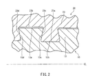
- FIG. 2 is an enlarged longitudinal sectional view of a threaded portion of the steel pipe threaded joint shown in FIG.
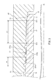
- FIG. 3 is an enlarged vertical cross-sectional view of the inner end portion in the pipe axis direction of the steel pipe threaded joint shown in FIG. 1.
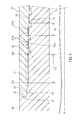
- FIG. 4 is an enlarged vertical cross-sectional view of the outer end portion in the tube axis direction of the steel pipe threaded joint shown in FIG. 1.
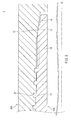
- FIG. 5 is an enlarged longitudinal sectional view of the inner end portion in the tube axis direction of a threaded joint for steel pipes according to a modification of the embodiment.
- FIG. 1 is a longitudinal sectional view showing a threaded joint for steel pipes according to an embodiment.
- FIG. 2 is an enlarged longitudinal sectional view of a threaded portion of the steel pipe threaded joint shown in FIG.
- FIG. 3 is an enlarged vertical cross-sectional
- FIG. 6 is an enlarged longitudinal sectional view of the outer end portion in the tube axis direction of a threaded joint for steel pipes according to a modified example different from the threaded joint for steel pipes shown in FIG.
- FIG. 7 is an enlarged longitudinal sectional view of the inner end portion in the pipe axis direction of a threaded joint for steel pipes according to a modification different from the threaded joint for steel pipes shown in FIGS. 5 and 6.
- FIG. 8 is an enlarged longitudinal sectional view of a threaded portion of a threaded joint for steel pipes according to a modified example different from the threaded joint for steel pipes shown in FIGS.
- FIG. 9 is a longitudinal sectional view showing a model of a threaded joint for steel pipes according to examples and comparative examples.
- FIG. 10 is an enlarged longitudinal sectional view of the outer end portion in the tube axis direction of the model of the threaded joint for steel pipes shown in FIG.
- FIG. 11 is an enlarged longitudinal sectional view of a thread portion of the model of the threaded joint for steel pipes shown in FIG.
- the inner diameter and outer diameter of the slim type threaded joint are strictly limited. For this reason, it is necessary to arrange
- the internal pressure may press the tip of the pin against the box, and can exhibit sealing performance against the internal pressure.
- the external pressure reaches the tip of the pin through the gap of the screw part and pushes down the tip of the thin pin, a gap is easily generated between the pin and the box when external pressure is applied. End up. Therefore, the configuration in which only the inner seal portion is provided cannot exhibit the sealing performance against the external pressure.
- the external pressure may press the end of the box against the pin, so that the sealing performance against the external pressure can be exhibited.
- the internal pressure reaches the end of the box through the gap of the screw part and pushes up the end of the thin box, a gap is easily generated between the pin and the box when internal pressure is applied. End up. Therefore, in the configuration in which only the outer seal portion is provided, the sealing performance against the internal pressure cannot be exhibited.
- the thread portion is necessarily composed of two stages of screws. That is, since the screw portion is divided into two parts, the wall thickness that can be used for each stage screw is naturally very small. As a result, there is almost no complete thread area, and the thread is full of incomplete thread areas, and the strength of the screw connection, particularly the tensile strength, is significantly reduced.
- the inventors of the threaded joint for steel pipes according to the embodiment further improve the sealing performance of the threaded joint in which the threaded part is configured by a single stage screw having a seal part on both the tip end side and the steel pipe body side.
- I have done research to improve it.
- the inventors have devised a pin tip portion (hereinafter also referred to as “pin lip portion”) provided with an inner seal portion and an end portion of a box provided with an outer seal portion (hereinafter referred to as “box lip portion”). It has been found that the sealing performance can be considerably improved by increasing the thickness of each of the above materials as much as possible.
- the inner diameter and outer diameter of the slim type threaded joint are strictly limited. Therefore, the inner diameter cannot be reduced to increase the thickness of the pin lip portion, and the outer diameter cannot be increased to increase the thickness of the box lip portion. For example, by shortening the screw length, lowering the thread height, or loosening the taper angle of the screw, etc., the wall thickness used by the screw part can be saved, and the pin lip and box lip It is also possible to increase the thickness of the part.
- the present inventors paid attention to the meshed state of the end of the threaded portion in the conventional threaded joint. Since the threaded portion is composed of a taper screw provided on the outer peripheral surface or inner peripheral surface of the pipe material, the top of the thread of the male thread or female thread is cut off at the end of the threaded part, and the thread height gradually decreases. Become. On the other hand, since the depth of the screw groove corresponding to these screw threads does not become shallow, a large space is generated between the screw thread top surface and the screw valley bottom surface at the end of the screw part even after screw coupling.
- the sealing performance can be further improved by effectively utilizing the region where the space is generated in the threaded joint.
- the inventors have increased the wall thickness of the pin lip and the box lip by gradually decreasing the depth of the thread groove in response to the height of the screw thread gradually decreasing at the end of the thread. I came up with the idea that I could make it bigger.
- the threaded joint for steel pipes according to the embodiment has been completed based on the above knowledge.
- the threaded joint for steel pipes according to the embodiment includes a tubular pin and a tubular box.
- a pin is screwed into a box and the pin and the box are fastened.
- the outer diameter of the box is smaller than 108% of the outer diameter of the steel pipe body.
- the pin includes a pin lip portion, a male screw portion, and a second seal surface in order from the tip toward the steel pipe body.
- the pin lip portion includes a first seal surface.
- the male thread portion is composed of a single stage taper screw.
- the box includes a first seal surface, an internal thread portion, and a box lip portion.
- the first seal surface corresponds to the first seal surface of the pin.
- the female screw portion corresponds to the male screw portion, and is constituted by a one-stage taper screw.
- the box lip includes a second seal surface corresponding to the second seal surface of the pin. In the fastened state, the first seal surfaces are in contact with each other and the second seal surfaces are in contact with each other.
- the male thread portion has a plurality of thread valley bottoms that are parallel to the tube axis and have the same diameter at the end on the pin lip portion side.
- the female thread portion has a plurality of thread valley bottoms that are parallel to the tube axis and have the same diameter at the end on the box lip portion side.
- the same diameter means the “same” diameter when machining with normal accuracy by a cutting device or cutting tool such as an NC lathe that is commonly used by those skilled in the art, and the average diameter is several hundred microns at most. It means that there is no difference of about a meter.
- the male screw portion and the female screw portion have “a plurality of thread valley bottoms that are parallel to the tube axis and have the same diameter” as used in the longitudinal sectional view of the threaded joint. It means that there are a plurality of thread valley bottoms that are the same.
- the male threaded portion has a plurality of thread valley bottoms parallel to the tube axis and having the same diameter at the end on the pin lip portion side.
- the wall thickness of the pin lip portion can be increased as compared with the case where all the thread valley bottom surfaces of the male screw portion are arranged along the tapered surface that is reduced in diameter toward the pin lip portion. Therefore, the elastic recovery force due to the interference amount of the first seal surface of the pin can be considerably increased, and the sealing performance against the internal pressure can be improved.
- the above threaded joint has a plurality of thread valley bottoms parallel to the tube axis and having the same diameter at the end on the box lip side. According to this configuration, the wall thickness of the box lip portion can be increased as compared with the case where all the thread valley bottom surfaces of the female screw portion are provided along the tapered surface that expands toward the box lip portion. Therefore, the elastic recovery force due to the interference amount of the second seal surface of the box can be considerably increased, and the sealing performance against external pressure can be improved.
- the male thread part and the female thread part are composed of a single taper screw.
- the wall thickness that can be used for the thread part is increased, and a complete thread part region can be sufficiently secured. Therefore, it is possible to suppress a decrease in the tensile strength of the screw connection, and to secure joint strength.
- the pin may further include a shoulder surface provided on at least one of the tip and the end surface on the steel pipe main body side.
- the box may further comprise a shoulder surface corresponding to the shoulder surface of the pin. In the fastened state, corresponding shoulder surfaces may contact each other.
- the pin may further include a first nose portion disposed between the tip surface and the first seal surface of the pin.
- the rigidity of the pin lip portion (elastic recovery force of the first seal surface of the pin) can be further improved. Therefore, the sealing performance against the internal pressure can be further improved.
- the box may further include a second nose portion disposed between an end surface corresponding to the end surface of the pin on the steel pipe body side and the second seal surface of the box.
- the rigidity of the box lip portion (elastic recovery force of the second seal surface of the box) can be further improved. Therefore, the sealing performance against external pressure can be further improved.
- the threaded portion composed of the male threaded portion and the female threaded portion has a dovetail shape in the longitudinal sectional shape of the screw (hereinafter simply referred to as a threaded shape), and the thread width gradually changes along the lead. It may be a thing.
- the thread portion constituted by the male thread portion and the female thread portion may be a single thread or a double thread.
- the distance in the tube axis direction from the male screw portion to the first seal surface of the pin may be 1.5 times or more the screw pitch in the male screw portion.
- the distance in the tube axis direction from the female thread portion to the second seal surface of the box may be 1.5 times or more the thread pitch in the female thread portion.
- FIG. 1 is a longitudinal sectional view showing a threaded joint 1 for steel pipes according to an embodiment.
- the threaded joint 1 is an integral type threaded joint, and includes a pin 10 and a box 20. However, the threaded joint 1 can also be applied to a coupling type threaded joint.
- the threaded joint 1 is a slim type with a small difference between the outer diameter of the box 20 and the outer diameter of the steel pipe body 30. For this reason, the outer diameter of the box 20 is smaller than 108% of the outer diameter of the steel pipe main body 30. The outer diameter of the box 20 is 100% or more of the outer diameter of the steel pipe main body 30.
- the steel pipe main body 30 is a part other than the pin 10 and the box 20 among the steel pipes connected by the threaded joint 1.
- the pin 10 includes a pin lip portion 12 including a first seal surface 11, a male screw portion 13, and a second seal surface 14 in order from the tip toward the steel pipe body 30.
- the pin 10 further includes a shoulder surface 15 at the end on the steel pipe main body 30 side.
- the inner diameter of the pin 10 is larger than the drift diameter defined by the API (American Petroleum Institute) standard.
- the tip side of the pin 10 may be referred to as the inner side in the tube axis direction
- the steel pipe main body 30 side of the pin 10 may be referred to as the outer side in the tube axis direction.
- the first seal surface 11 is provided on the outer peripheral surface of the pin lip portion 12 extending from the male screw portion 13 to the front end side.
- the second seal surface 14 is provided on the outer peripheral surface of the pin 10 closer to the steel pipe body 30 than the male screw portion 13. Therefore, the male screw portion 13 is disposed between the first seal surface 11 and the second seal surface 14 on the outer peripheral surface of the pin 10.
- the first seal surface 11 and the second seal surface 14 are both tapered. Strictly speaking, each of the first seal surface 11 and the second seal surface 14 is formed of a surface corresponding to the peripheral surface of the truncated cone whose diameter is reduced toward the tip side, or the peripheral surface of the truncated cone, an arc, or the like. These curves have a shape corresponding to the peripheral surface of the rotating body obtained by rotating the curve around the tube axis CL, or a combination of both.
- the shoulder surface 15 is an annular surface substantially perpendicular to the tube axis CL.
- the shoulder surface 15 is slightly inclined from the surface perpendicular to the tube axis CL in the screwing direction of the pin 10, that is, the outer peripheral side is slightly inclined toward the tip side of the pin 10. Is shown.
- the box 20 includes a box lip portion 22 including a first seal surface 21, a female screw portion 23, and a second seal surface 24 in order from the inner side to the outer side in the tube axis direction.
- the box 20 further comprises a shoulder surface 25 at its outer end.
- the first seal surface 21, the female screw portion 23, the second seal surface 24, and the shoulder surface 25 of the box 20 are respectively the first seal surface 11, the male screw portion 13, the second seal surface 14, and the shoulder surface 15 of the pin 10. It is provided corresponding to.
- the male threaded portion 13 of the pin 10 and the female threaded portion 23 of the box 20 are composed of one-stage taper screws that mesh with each other.
- the screw shapes of the male screw portion 13 and the female screw portion 23 are dovetail shapes.
- the screw widths of the male screw portion 13 and the female screw portion 23 change in the direction in which the pin 10 is screwed. Specifically, the thread width of the male thread portion 13 is tapered narrower in the direction in which the right screw advances along the thread winding (lead) of the screw, and the thread groove width of the opposing female thread portion 23 is also the string winding of the screw. Along the direction of the right-handed screw.
- the male screw portion 13 and the female screw portion 23 can be screwed together.
- the first seal surfaces 11, 21 and the second seal surfaces 14, 24 come into contact with each other as the pin 10 is screwed in, and in a fastened state, they are fitted together and brought into a tight fit state.
- the 1st seal surfaces 11 and 21 form the 1st seal part (inner seal part) by metal contact.
- the second seal surfaces 14 and 24 form a second seal portion (outer seal portion) by metal contact.
- the shoulder surfaces 15 and 25 are pressed against each other by screwing the pin 10 into the box 20 and play a role of a stopper for restricting the screwing of the pin 10. Furthermore, the shoulder surfaces 15 and 25 have a role of applying a load in the opposite direction (backward) to the screwing direction (forward), that is, a so-called screw tightening axial force, to the male threaded portion 13 of the pin 10 in the fastening state. Bear.
- the shoulder surfaces 15 and 25 form a shoulder portion by such a pressing contact with each other.
- FIG. 2 is an enlarged longitudinal sectional view of the threaded portion of the threaded joint 1.
- the screw portion is composed of a male screw portion 13 of the pin 10 and a female screw portion 23 of the box 20.
- the thread portion is preferably a single thread or a double thread.
- the male thread portion 13 of the pin 10 includes a plurality of thread crest top surfaces 13a, a thread trough bottom surface 13b, an insertion flank surface 13c (hereinafter also referred to as “insertion surface”), and the insertion thereof.
- a load flank surface 13d (hereinafter also referred to as a “load surface”) opposite to the surface 13c is provided.
- the female screw portion 23 of the box 20 includes a plurality of screw thread top surfaces 23a, screw valley bottom surfaces 23b, insertion surfaces 23c, and load surfaces 23d. Each screw thread top surface 23 a of the female screw portion 23 faces the thread valley bottom surface 13 b of the male screw portion 13.
- Each thread valley bottom surface 23 b of the female screw portion 23 faces the screw thread top surface 13 a of the male screw portion 13.
- Each insertion surface 23 c of the female screw portion 23 faces the insertion surface 13 c of the male screw portion 13.
- Each load surface 23 d of the female screw portion 23 faces the load surface 13 d of the male screw portion 13.
- flank angles of the load surfaces 13d and 23d and the insertion surfaces 13c and 23c of the male screw portion 13 and the female screw portion 23 are all negative angles of less than 0 °.
- the flank angle is an angle formed by a plane perpendicular to the tube axis CL and the flank surface.
- the flank angle of the load surfaces 13d and 23d is positive in the clockwise direction
- the flank angle of the insertion surfaces 13c and 23c is positive in the counterclockwise direction.
- the load surfaces 13 d and 23 d of the male screw portion 13 and the female screw portion 23 and the insertion surfaces 13 c and 23 c are in contact with each other, and the thread valley bottom surface 13 b of the male screw portion 13 and the screw thread top surface 23 a of the female screw portion 23 are formed. They are in contact with each other.
- a gap is formed between the screw thread top surface 13 a of the male screw portion 13 and the screw valley bottom surface 23 b of the female screw portion 23.
- the screw thread top surface 13a of the male screw part 13 and the thread valley bottom surface 23b of the female screw part 23 are in contact with each other, and the screw thread bottom surface 13b of the male screw part 13 and the screw thread top surface of the female screw part 23 are in contact with each other. It may be an aspect in which a gap is formed with respect to 23a. Further, a gap may be formed between the insertion surfaces 13 c and 23 c of the male screw portion 13 and the female screw portion 23.
- FIG. 3 is an enlarged vertical cross-sectional view of the end portion (inner end portion in the tube axis direction) of the threaded joint 1 on the pin lip portion 12 side.
- the male screw portion 13 has a plurality of thread valley bottom surfaces 131 b that are parallel to the tube axis CL and have the same diameter at the end on the pin lip portion 12 side.
- two or more thread valley bottom surfaces 131b from the inner end in the tube axis direction each have a substantially cylindrical shape. That is, each thread valley bottom face 131b is formed of a cylindrical surface having the tube axis CL as an axis.
- the depth of the thread groove at the inner end portion of the male screw portion 13 gradually decreases toward the pin lip portion 12.
- those other than the thread valley bottom surface 131b each have a shape along the peripheral surface of the truncated cone, the diameter of which decreases as it approaches the pin lip portion 12.
- the screw thread top surface 231a corresponding to the thread valley bottom surface 131b of the male screw part 13 is configured to be parallel to the pipe axis CL and have the same diameter. That is, in the female thread portion 23, two or more thread crest surfaces 231a from the inner end in the tube axis direction are parallel to the tube axis CL and have the same diameter.
- the screw thread top surface 231a is arranged coaxially with the thread valley bottom surface 131b of the corresponding male screw part 13, and has a cylindrical surface shape slightly larger in diameter than the thread valley bottom surface 131b.
- a gap C1 is generated between each screw thread top surface 231a and the corresponding thread valley bottom surface 131b of the male screw portion 13.
- those other than the screw thread top surface 231a each have a shape along the peripheral surface of the truncated cone whose diameter decreases toward the inside in the tube axis direction.
- the gap C1 is caused by the difference between the diameter of the cylindrical surface constituting the screw thread top surface 231a of the female screw portion 23 and the diameter of the cylindrical surface constituting the thread valley bottom surface 131b of the male screw portion 13.
- the average diameter of C1 is larger than 0 ⁇ m and not larger than 900 ⁇ m, more preferably not larger than 500 ⁇ m in a state where the threaded joint is fastened.
- the average diameter is described here because an actual product has an elliptic error, and C1 is rarely uniform over the entire circumference. Therefore, depending on the case, there may be a portion where C1 is zero in a part in the circumferential direction, and there may be a portion where the maximum gap exceeds 900 ⁇ m.
- the first seal surface 11 of the pin lip portion 12 contacts the first seal surface 21 of the box 20 in the fastened state.
- the region other than the first seal surface 11 does not contact the box 20 in the fastening state.
- the distance L1 in the tube axis direction from the male screw portion 13 to the first seal portion is preferably, for example, 1.5 times or more the screw pitch P1.
- the distance L1 is the length in the tube axis direction from the outer end E11 of the first seal surface 11 that is in contact with the first seal surface 21 of the box 20 to the inner end E12 of the male screw portion 13.
- the thread pitch P1 refers to the length in the tube axis direction between the load surfaces of adjacent threads in the male thread portion 13 (in this specification, the thread pitch in the case of a double thread is also defined).
- FIG. 4 is an enlarged vertical cross-sectional view of the end portion (outer end portion in the tube axis direction) of the threaded joint 1 on the box lip portion 22 side.
- the female screw portion 23 has a plurality of thread valley bottom surfaces 231 b that are parallel to the tube axis CL and have the same diameter at the end portion on the box lip portion 22 side.
- two or more thread valley bottom surfaces 231b from the outer end in the tube axis direction have a substantially cylindrical shape. That is, each thread valley bottom surface 231b is configured by a cylindrical surface having the tube axis CL as an axis.
- the depth of the thread groove at the outer end portion of the internal thread portion 23 gradually decreases toward the box lip portion 22.
- those other than the thread valley bottom surface 231b each have a shape along the peripheral surface of the truncated cone whose diameter decreases as the distance from the box lip portion 22 increases.
- the screw thread top surface 131a corresponding to the thread valley bottom surface 231b of the female screw part 23 is configured to be parallel to the pipe axis CL and have the same diameter. That is, in the male thread portion 13, two or more thread crest surfaces 131a from the outer end in the tube axis direction are parallel to the tube axis CL and have the same diameter.
- the screw thread top surface 131a is arranged coaxially with the thread valley bottom surface 231b of the corresponding female screw part 23, and has a cylindrical surface shape slightly smaller in diameter than the thread valley bottom surface 231b.
- a gap C2 is generated between each screw thread top surface 131a and the corresponding screw thread bottom surface 231b of the female screw portion 23.
- those other than the screw thread top surface 131a each have a shape along the peripheral surface of the truncated cone whose diameter decreases toward the inside in the tube axis direction.
- the gap C2 is caused by the difference between the diameter of the cylindrical surface constituting the screw thread top surface 131a of the male screw portion 13 and the diameter of the cylindrical surface constituting the thread valley bottom surface 231b of the female screw portion 23.
- the average diameter of C2 is larger than 0 ⁇ m and not larger than 900 ⁇ m, more preferably not larger than 500 ⁇ m, in a state where the threaded joint is fastened.
- the average diameter is described for the same reason as C1 described above.
- the second seal surface 24 of the box lip portion 22 contacts the second seal surface 14 of the pin 10 in the fastened state.
- regions other than the second seal surface 24 and the shoulder surface 25 do not contact the pin 10 in the fastening state.
- the distance L2 in the tube axis direction from the female screw portion 23 to the second seal portion is preferably, for example, 1.5 times or more the screw pitch P2.
- the distance L2 is the length in the tube axis direction from the inner end E21 of the second seal surface 24 in contact with the second seal portion 14 of the pin 10 to the outer end E22 of the female screw portion 23.
- the thread pitch P ⁇ b> 2 refers to the length in the tube axis direction between the load surfaces of adjacent screw threads in the female thread portion 23.
- the male thread portion 13 has a plurality of thread valley bottom surfaces 131b that are parallel to the tube axis CL and have the same diameter at the end portion on the pin lip portion 12 side. . Therefore, the wall thickness of the pin lip portion 12 can be increased as compared with the case where all the thread valley bottom surfaces of the male screw portion 13 are arranged along the tapered surface that is reduced in diameter as it approaches the pin lip portion 12 side.
- the female thread portion 23 has a plurality of thread valley bottom surfaces 231b that are parallel to the tube axis CL and have the same diameter at the end portion on the box lip portion 22 side. Therefore, the wall thickness of the box lip portion 22 can be increased as compared with the case where all the thread valley bottom surfaces of the female screw portion 23 are provided along the taper surface whose diameter is increased as approaching the box lip portion 22 side.
- the male screw portion 13 and the female screw portion 23 are configured by a single stage taper screw. For this reason, in the threaded joint 1, compared to a threaded joint in which the threaded part is configured in two stages, the wall thickness that can be used for the threaded part is increased, and a complete threaded part region can be sufficiently secured. it can. Therefore, it is possible to suppress a decrease in the tensile strength of the screw connection, and to secure joint strength.
- the present embodiment it is possible to secure the thicknesses of the pin lip portion 12 in which the inner seal portion is disposed and the box lip portion 22 in which the outer seal portion is disposed.
- the sealing performance can be improved.
- the joint strength, particularly the tensile strength does not decrease in order to improve the sealing performance.
- the thread valley bottom surface 131b arranged at the end on the pin lip portion 12 side in the male screw portion 13 has a cylindrical surface shape that is slightly smaller in diameter than the screw thread top surface 231a of the corresponding female screw portion 23.
- the gap C1 between the thread valley bottom surface 131b of the male screw portion 13 and the screw thread top surface 231a of the female screw portion 23 becomes small at the inner end portion of the screw portion.
- the thread valley bottom surface 231b disposed at the end of the female screw portion 23 on the box lip portion 22 side has a cylindrical surface shape that is slightly larger in diameter than the thread top surface 131a of the corresponding male screw portion 13.
- the gap C2 between the thread valley bottom surface 231b of the female screw portion 23 and the screw thread top surface 131a of the male screw portion 13 becomes small at the outer end portion of the screw portion. That is, in the present embodiment, the space formed between the screw thread top surface and the screw valley bottom surface at the inner and outer end portions of the screw portion constituted by the taper screw is smaller than the conventional one. According to the present inventors, the thickness that can be used for the pin lip portion 12 and the box lip portion 22 is increased by adopting such a configuration. Therefore, the sealing performance against the internal pressure and the external pressure can be further improved.
- the shoulder surface 15 is provided at the end of the pin 10 on the steel pipe main body 30 side.
- the box 20 is provided with a shoulder surface 25 corresponding to the shoulder surface 15 of the pin 10. Since each shoulder surface 15 and 25 is in contact with each other in the fastened state, it can function as a stopper that restricts screwing of the pin 10 into the box 20. Moreover, each shoulder surface 15 and 25 can generate
- the screw portion constituted by the male screw portion 13 and the female screw portion 23 has a dovetail shape, and the screw width changes. According to this configuration, since the load surfaces are in contact with each other and the screw thread top surface and the screw valley bottom surface are in contact with each other and are in close contact with each other, excellent sealing performance can be realized. When the insertion surfaces come into contact with each other when the fastening of the pin 10 and the box 20 is completed, the entire screw portion fits firmly, and the adhesion performance can be further improved.
- first seal part and the second seal face and the second seal faces 14 and 24 are brought into close contact with each other with an appropriate contact force over the entire circumference so as to exhibit sealing performance.
- Each of the two seal portions has a fitting allowance (interference amount). For this reason, if the distance between the first seal portion and / or the second seal portion and the screw portion in the tube axis direction is too close, the internal thread portion 23 is externally threaded due to the amount of interference between the first seal portion and / or the second seal portion. It peels off from the part 13, and the intensity
- the distance L1 in the tube axis direction from the screw portion to the first seal portion is such that the contact between the first seal surfaces 11 and 21 and the contact between the male screw portion 13 and the female screw portion 23 do not adversely affect each other. It is secured. Further, a distance L2 in the tube axis direction from the threaded portion to the second seal portion is ensured so that the contact between the second seal surfaces 14 and 24 and the contact between the male threaded portion 13 and the female threaded portion 23 do not adversely affect each other. Yes.
- the distances L1 and L2 are 1.5 times longer than the screw pitches P1 and P2, respectively. Thereby, it can suppress that the intensity
- the roundness varies depending on, for example, the outer diameter, thickness and material of the steel pipe, the manufacturing method, and the like. However, the roundness is generally not less than 5% and not more than 50% of the height (radial dimension) of the lower load surface of the complete thread of the external thread 13 and the complete thread of the internal thread 23. More preferably, it is 10% or more and 30% or less.
- the thread height and thread taper of the thread part are not particularly limited.
- the thread height and the thread taper can be appropriately adjusted in accordance with, for example, the outer diameter or thickness of the steel pipe.
- the thread height can be set in a range of approximately 0.8 mm to 3 mm.
- the thread taper can be set in a range of approximately 1/21 to 1/4.
- each flank angle on the load surface and the insertion surface is practically ⁇ 31 ° or more and less than 0 °. can do.
- the size of each flank angle on the load surface and the insertion surface is more preferably ⁇ 16 ° to ⁇ 2 ° from the viewpoint of manufacturability and the like.
- the size of the flank angle of the load surface and the size of the flank angle of the insertion surface may not be the same.
- a threaded joint for steel pipes called a flash type, a semi-flash type, a slim type, or the like, in which the difference between the outer diameter of the box 20 and the outer diameter of the steel pipe main body 30 is small.
- the outer diameter of the box 20 is 108% or less of the outer diameter of the steel pipe main body 30.
- the outer diameter of the box 20 is 104% or less of the outer diameter of the steel pipe body 30.
- the inner diameter of the threaded joint 1 (the inner diameter of the pin 10) is, for example, the lower limit of the drift diameter of API standard SPEC5CT.
- first seal surfaces 11 and 21 and the second seal surfaces 14 and 24 are not particularly limited.
- the outlines of the first seal surfaces 11 and 21 and the second seal surfaces 14 and 24 are straight lines, arcs, elliptical arcs, or smooth convex curves. Or a combination thereof.
- the distance between the first seal portion and / or the second seal portion and the screw portion in the tube axis direction is too close, the female screw portion 23 is caused by the amount of interference between the first seal portion and / or the second seal portion. Is peeled off from the male screw part 13, and the strength of the screw connection is reduced at the end of the screw part. Therefore, although depending on the outer diameter and thickness of the threaded joint 1, the distance L1 in the tube axis direction from the screw portion to the first seal portion and the distance L2 in the tube axis direction from the screw portion to the second seal portion. Are preferably 1.5 times or more of the thread pitches P1 and P2. From the viewpoint of manufacturing cost, handleability, and the like, the distances L1 and L2 can be set to 5 times or less of the screw pitches P1 and P2, respectively.
- the tensile strength in the circumferential direction at the end of the box 20 can be increased by cold pipe expansion or the like.
- the tensile strength in the circumferential direction of the second seal surface 24 of the box 20 is preferably increased by at least 5%, more preferably increased by 10% or more, compared with the tensile strength of the steel pipe body 30.
- the pin or the box may include a nose portion.
- FIG. 5 is an enlarged longitudinal sectional view of the inner end portion in the tube axis direction of the threaded joint 2 for a steel pipe according to a modification of the above embodiment.
- the steel pipe threaded joint 2 is different from the steel pipe threaded joint 1 according to the above-described embodiment in that the pin 10 ⁇ / b> A includes a nose portion 16.
- the nose portion 16 is installed on the innermost side of the pin lip portion 12 in the tube axis direction.
- the nose portion 16 is disposed between the tip surface of the pin 10A and the first seal surface 11 of the pin 10A.
- a shoulder surface similar to that of the above embodiment may be provided at each outer end portion of the pin 10A and the box 20A in the tube axis direction, or a shoulder surface may not be provided. .
- the outer peripheral surface of the nose portion 16 does not contact the box 20A.
- FIG. 6 is an enlarged vertical cross-sectional view of the outer end portion in the tube axis direction of the threaded joint 3 for steel pipes according to a modification of the above embodiment.
- the threaded joint 3 for a steel pipe is different from the threaded joint 1 for a steel pipe according to the above-described embodiment in that the box 20B includes a nose portion 26.
- the nose portion 26 is installed on the outermost side of the box lip portion 22 in the tube axis direction.
- the nose portion 26 is disposed between the second seal surface 24 of the box 20B and the shoulder surface 25 of the box 20B. That is, a shoulder surface 25 is provided at the tip of the nose portion 26.
- the shoulder surface 25 of the box 20B is in contact with the shoulder surface 15 of the pin 10B as in the above embodiment, but the inner peripheral surface of the nose portion 26 is not in contact with the pin 10B.
- the tensile strength in the circumferential direction of the box lip portion 22 including the nose portion 26 and the second seal surface 24 of the box 20B can be increased by cold tube expansion processing or the like.
- the tensile strength in the circumferential direction of the nose portion 26 and the second seal surface 24 is preferably increased by at least 5%, more preferably increased by 10% or more than the tensile strength of the steel pipe body.
- FIG. 5 and 6 show an example in which a nose portion is provided on a pin or a box.
- the nose portion may be provided on both the pin and the box.
- the shoulder surface is not provided at the tip of the pin, but as shown in FIG. 7, the shoulder surface 17 may be provided at the tip of the pin 10C.
- the box 20C includes a shoulder surface 27 corresponding to the shoulder surface 17 of the pin 10C. In the fastened state, the shoulder surface 17 of the pin 10C comes into contact with the shoulder surface 27 of the box 20C.
- a shoulder surface similar to that of the above embodiment may or may not be provided on the end surface of the pin 10C on the steel pipe main body side.
- the shoulder surface of the pin can be provided on one or both of the tip end of the pin and the end surface on the steel pipe main body side.
- the box is provided with a shoulder surface corresponding to each of the one or more shoulder surfaces of the pin.
- the screw portion is constituted by a dovetail-shaped screw, but the screw shape of the screw portion is not particularly limited thereto.
- the male screw portion 13A (13) and the female screw portion 23A (23) may be formed of trapezoidal screws.
- the male threaded portion 13A (13) has a plurality of thread valley bottoms parallel to the tube axis CL and having the same diameter at the inner end in the tube axis direction
- the female threaded portion 23A (23 ) Has a plurality of thread valley bottoms parallel to the tube axis CL and having the same diameter at the outer end in the tube axis direction.
- the model of the threaded joint for steel pipes used for the elastoplastic finite element analysis was composed of the inner seal portion constituted by the first seal surfaces 11 and 21 and the second seal surfaces 14 and 24.
- An outer seal part, a shoulder part constituted by shoulder surfaces 15 and 25, and a nose part 26 disposed between the outer seal part and the shoulder part are provided.
- the basic configurations of the models of Examples and Comparative Examples described later are the same.
- a model in which the technology according to the present disclosure was applied to the threaded joint having the basic configuration described above was produced. That is, as shown in FIG. 10, at the outer end of the threaded portion in the tube axis direction, the plurality of thread valley bottom surfaces of the internally threaded portion 23 and the corresponding thread top surface of the external threaded portion 13 are parallel to the tube axis CL. It is. Although not shown, at the inner end of the threaded portion in the tube axis direction, the plurality of thread valley bottom surfaces of the male threaded portion 13 and the thread top surface of the female threaded portion 23 corresponding thereto are parallel to the tube axis CL.
- the pin lip has a thickness of 6.11 mm
- the box lip has a thickness of 7.19 mm.
- the distance in the tube axis direction from the male screw portion 13 to the inner seal portion is twice the screw pitch.
- the distance in the tube axis direction from the female screw portion 23 to the outer seal portion was also twice the screw pitch.
- thread width and thread groove width change in the screwing direction inserted between the thread top surface of the external thread and the thread bottom surface of the internal thread in the fastening state
- the thread height is about 2 mm
- the thread pitch is 8.47 mm
- the thread taper is 1/10, single thread, each distance between the thread part and the inner seal part and the outer seal part: 19 mm ⁇
- the sealing surface pressure of the inner and outer seal portions in the example is much higher than the sealing surface pressure of the inner and outer seal portions in the comparative example. From this, it can be seen that the threaded joint for steel pipes according to the present disclosure has a wall thickness of the pin lip portion and the box lip portion that is larger than that of the prior art, and as a result, has excellent sealing performance against external pressure and internal pressure.
Landscapes
- Engineering & Computer Science (AREA)
- General Engineering & Computer Science (AREA)
- Mechanical Engineering (AREA)
- Mining & Mineral Resources (AREA)
- Life Sciences & Earth Sciences (AREA)
- Geology (AREA)
- Fluid Mechanics (AREA)
- Environmental & Geological Engineering (AREA)
- Physics & Mathematics (AREA)
- General Life Sciences & Earth Sciences (AREA)
- Geochemistry & Mineralogy (AREA)
- Non-Disconnectible Joints And Screw-Threaded Joints (AREA)
- Mutual Connection Of Rods And Tubes (AREA)
Abstract
Description
以下、鋼管用ねじ継手の実施形態について図面を参照しつつ説明する。図中同一及び相
当する構成については同一の符号を付し、同じ説明を繰り返さない。
上述したように、ねじ部の管軸方向の内端部において、雄ねじ部13のねじ谷底面131bと、これに対応する雌ねじ部23の各ねじ山頂面231aとの間には隙間C1が存在する。ねじ部の管軸方向の外端部において、雄ねじ部13の各ねじ山頂面131aと、これに対応する雌ねじ部23のねじ谷底面231bとの間には隙間C2が生じる。隙間C1、C2は、ぞれぞれ、ねじ部の管軸方向の内端部及び外端部の真円度(楕円率)のばらつき(製造公差)に応じて設定するのが好ましい。真円度は、例えば、鋼管の外径、肉厚サイズや材質、製造方法等によってさまざまに変化する。しかしながら、真円度は、概して、雄ねじ部13の完全ねじ山及び雌ねじ部23の完全ねじ山のうち低い方の荷重面の高さ(径方向の寸法)の概ね5%以上50%以下であり、より好ましくは10%以上30%以下である。
本実施形態では、特に、ボックス20の外径と鋼管本体30の外径との差が小さいフラッシュ型、セミフラッシュ型、及びスリム型等と呼ばれる鋼管用ねじ継手が対象とされる。上述した通り、本実施形態に係る鋼管用ねじ継手1において、ボックス20の外径は、鋼管本体30の外径の108%以下である。特に、ボックス20の外径と鋼管本体30の外径との差がより小さいフラッシュ型及びセミフラッシュ型のねじ継手の場合、ボックス20の外径は、鋼管本体30の外径の104%以下である。ねじ継手1の内径(ピン10の内径)は、例えば、API規格のSPEC5CTのドリフト径を下限とする。
第1シール面11、21及び第2シール面14、24それぞれの形状及び寸法は、特に限定されるものではない。ねじ継手1の縦断面(管軸CLを含む平面で切断した断面)において、第1シール面11、21及び第2シール面14、24の輪郭は、直線、円弧、楕円弧、もしくは滑らかな凸曲線、又はこれらの組み合わせで構成することができる。
上述したように、第1シール部及び/又は第2シール部とねじ部との管軸方向の距離があまりに近すぎると、第1シール部及び/又は第2シール部の干渉量によって雌ねじ部23が雄ねじ部13から引き剥がされ、ねじ部の端部においてねじ結合の強度が低下してしまう。よって、ねじ継手1の外径や肉厚サイズ等にもよるが、ねじ部から第1シール部までの管軸方向の距離L1、及びねじ部から第2シール部までの管軸方向の距離L2は、それぞれ、ねじピッチP1、P2の1.5倍以上であることが好ましい。製造コストや取扱性等の観点から、距離L1、L2は、それぞれ、ねじピッチP1、P2の5倍以下とすることができる。
ボックス20の端部における周方向の引張耐力は、冷間拡管加工等によって高めることができる。例えば、ボックス20の第2シール面24における周方向の引張耐力は、鋼管本体30の引張耐力よりも少なくとも5%以上高めることが好ましく、10%以上高めることがより好ましい。
以上、実施形態について説明したが、本開示は上記実施形態に限定されるものではなく、その趣旨を逸脱しない限りにおいて種々の変更が可能である。例えば、図5及び図6に示すように、ピン又はボックスがノーズ部を備えていてもよい。
図9に示すように、弾塑性有限要素解析に用いた鋼管用ねじ継手のモデルは、第1シール面11、21で構成された内シール部と、第2シール面14、24で構成された外シール部と、ショルダ面15、25で構成されるショルダ部と、外シール部とショルダ部との間に配置されたノーズ部26とを備える。後述する実施例及び比較例のモデルの基本構成は同一である。
・鋼管の寸法:14[inch]、115[lb/ft](公称外径がφ355.6mm、公称肉厚が20.63mm)
・鋼管のグレード:API規格のQ125(API 5CTで規定される油井管用炭素鋼、降伏強度が125ksi(862N/mm2))
・ねじの形状及び寸法:ダブテイル形状(図11参照)、ねじ込み進行方向にねじ山幅及びねじ溝幅が変化、締結状態において雄ねじ部のねじ山頂面と雌ねじ部のねじ谷底面との間及び挿入面間に隙間あり、ねじ山高さが約2mm、ねじピッチが8.47mm、ねじテーパが1/10、一条ねじ
・ねじ部と内シール部及び外シール部との各距離:19mm
・ノーズ部の管軸方向の長さ:20mm
弾塑性有限要素解析では、作製した各モデルについて、ショルダリング(ショルダ面15、25同士が突き当たること)からさらに管軸方向に0.001インチ締め込み、ISO13679:2002年版のシリーズA試験(常温下の繰返し内圧、外圧負荷試験)を模擬した荷重組合せを順次負荷した。その解析過程における内外シール部の密封面圧の最小値を、比較例の値を1として相対値で比較した。解析結果を表1に示す。

Claims (6)
- 管状のピンと、管状のボックスとから構成され、前記ピンが前記ボックスにねじ込まれて前記ピンと前記ボックスとが締結される鋼管用ねじ継手であって、
前記ボックスの外径は、鋼管本体の外径の108%よりも小さく、
前記ピンは、先端から鋼管本体に向けて順に、第1シール面を含むピンリップ部、1段のテーパねじで構成される雄ねじ部、及び第2シール面を備え、
前記ボックスは、前記ピンの第1シール面に対応する第1シール面、前記雄ねじ部に対
応し1段のテーパねじで構成される雌ねじ部、及び前記ピンの第2シール面に対応する第2シール面を含むボックスリップ部を備え、
締結状態において、前記第1シール面同士が接触するとともに、前記第2シール面同士が接触し、
前記雄ねじ部は、前記ピンリップ部側の端部において、管軸と平行かつ径が同じである複数のねじ谷底面を有し、
前記雌ねじ部は、前記ボックスリップ部側の端部において、管軸と平行かつ径が同じである複数のねじ谷底面を有する、鋼管用ねじ継手。 - 請求項1に記載の鋼管用ねじ継手であって、
前記ピンは、さらに、先端及び鋼管本体側の端面の少なくとも一方に設けられるショルダ面を備え、
前記ボックスは、さらに、前記ピンのショルダ面に対応するショルダ面を備え、
締結状態において、対応する前記ショルダ面同士が接触する、鋼管用ねじ継手。 - 請求項1又は2に記載の鋼管用ねじ継手であって、
前記ピンは、さらに、先端面と前記ピンの第1シール面との間に配置される第1ノーズ部を備える、鋼管用ねじ継手。 - 請求項1から3のいずれか1項に記載の鋼管用ねじ継手であって、
前記ボックスは、さらに、ピンの鋼管本体側の端面に対応する端面と前記ボックスの第2シール面との間に配置される第2ノーズ部を備える、鋼管用ねじ継手。 - 請求項1から4のいずれか1項に記載の鋼管用ねじ継手であって、
前記雄ねじ部と前記雌ねじ部とで構成されるねじ部は、ねじ形状がダブテイル形状であり、ねじ幅がリードに沿って変化する、鋼管用ねじ継手。 - 請求項1から5のいずれか1項に記載の鋼管用ねじ継手であって、
前記雄ねじ部と前記雌ねじ部とで構成されるねじ部は、1条ねじ又は2条ねじである、鋼管用ねじ継手。
Priority Applications (12)
| Application Number | Priority Date | Filing Date | Title |
|---|---|---|---|
| PL16857345T PL3366968T3 (pl) | 2015-10-21 | 2016-10-13 | Połączenie gwintowe dla rur stalowych |
| EP16857345.9A EP3366968B1 (en) | 2015-10-21 | 2016-10-13 | Threaded fitting for steel pipes |
| MX2018004757A MX2018004757A (es) | 2015-10-21 | 2016-10-13 | Conexion roscada para tubo de acero. |
| UAA201804345A UA122422C2 (uk) | 2015-10-21 | 2016-10-13 | Нарізне з’єднання для сталевої труби |
| EA201890784A EA035105B1 (ru) | 2015-10-21 | 2016-10-13 | Резьбовое соединение для стальной трубы |
| JP2017546515A JP6654643B2 (ja) | 2015-10-21 | 2016-10-13 | 鋼管用ねじ継手 |
| CN201680059893.4A CN108138994B (zh) | 2015-10-21 | 2016-10-13 | 钢管用螺纹接头 |
| CA3001670A CA3001670C (en) | 2015-10-21 | 2016-10-13 | Threaded connection for steel pipe |
| BR112018003384-7A BR112018003384B1 (pt) | 2015-10-21 | 2016-10-13 | Conexão roscada para tubulação de aço |
| AU2016340415A AU2016340415B2 (en) | 2015-10-21 | 2016-10-13 | Threaded connection for steel pipe |
| MYPI2018700395A MY182111A (en) | 2015-10-21 | 2016-10-13 | Threaded connection for steel pipe |
| US15/768,379 US10883319B2 (en) | 2015-10-21 | 2016-10-13 | Threaded connection for steel pipe |
Applications Claiming Priority (2)
| Application Number | Priority Date | Filing Date | Title |
|---|---|---|---|
| JP2015207145 | 2015-10-21 | ||
| JP2015-207145 | 2015-10-21 |
Publications (1)
| Publication Number | Publication Date |
|---|---|
| WO2017069030A1 true WO2017069030A1 (ja) | 2017-04-27 |
Family
ID=58557296
Family Applications (1)
| Application Number | Title | Priority Date | Filing Date |
|---|---|---|---|
| PCT/JP2016/080321 Ceased WO2017069030A1 (ja) | 2015-10-21 | 2016-10-13 | 鋼管用ねじ継手 |
Country Status (13)
| Country | Link |
|---|---|
| US (1) | US10883319B2 (ja) |
| EP (1) | EP3366968B1 (ja) |
| JP (1) | JP6654643B2 (ja) |
| CN (1) | CN108138994B (ja) |
| AU (1) | AU2016340415B2 (ja) |
| BR (1) | BR112018003384B1 (ja) |
| CA (1) | CA3001670C (ja) |
| EA (1) | EA035105B1 (ja) |
| MX (1) | MX2018004757A (ja) |
| MY (1) | MY182111A (ja) |
| PL (1) | PL3366968T3 (ja) |
| UA (1) | UA122422C2 (ja) |
| WO (1) | WO2017069030A1 (ja) |
Cited By (5)
| Publication number | Priority date | Publication date | Assignee | Title |
|---|---|---|---|---|
| JPWO2019171899A1 (ja) * | 2018-03-05 | 2020-04-16 | Jfeスチール株式会社 | 油井管用ねじ継手 |
| EP3708892A4 (en) * | 2017-11-09 | 2020-11-25 | Nippon Steel Corporation | THREADED FITTING FOR STEEL PIPES |
| JP2020537723A (ja) * | 2017-10-20 | 2020-12-24 | ヴァルレック オイル アンド ガス フランス | 部分的に自動ロック式に係合するねじ接続部 |
| JP2022066552A (ja) * | 2017-10-12 | 2022-04-28 | 三菱鉛筆株式会社 | 筆記具 |
| JPWO2024106291A1 (ja) * | 2022-11-15 | 2024-05-23 |
Families Citing this family (9)
| Publication number | Priority date | Publication date | Assignee | Title |
|---|---|---|---|---|
| RU2757621C1 (ru) * | 2018-10-02 | 2021-10-19 | Ниппон Стил Корпорейшн | Резьбовое соединение для стальных труб |
| CA3115198C (en) * | 2018-10-11 | 2023-06-13 | Nippon Steel Corporation | Threaded connection for steel pipe |
| CN115854135B (zh) * | 2019-03-27 | 2025-10-14 | 日本制铁株式会社 | 钢管用螺纹接头 |
| CN114080486B (zh) * | 2019-07-12 | 2025-10-28 | 海德瑞公司 | 用于烃井的勘探和生产的螺纹连接 |
| CN110608321B (zh) * | 2019-08-30 | 2024-07-23 | 江苏璞腾油气装备有限公司 | 一种双线海洋隔水管接头 |
| CN113739674A (zh) * | 2020-05-29 | 2021-12-03 | 宝山钢铁股份有限公司 | 一种用于螺纹接头上螺纹齿宽的检验量规及其检验方法 |
| CN114322716B (zh) * | 2020-09-29 | 2023-11-14 | 宝山钢铁股份有限公司 | 检测螺纹油套管上密封面轮廓误差的校对仪及其校对方法 |
| US12287048B2 (en) * | 2022-11-01 | 2025-04-29 | Saudi Arabian Oil Company | Pipe connection systems in oil and gas applications |
| AU2024272329A1 (en) * | 2023-05-18 | 2025-11-20 | National Oilwell Varco, L.P. | Threaded tubular members employing metal-to-metal seals |
Citations (8)
| Publication number | Priority date | Publication date | Assignee | Title |
|---|---|---|---|---|
| JPS6347588A (ja) * | 1986-07-22 | 1988-02-29 | ブリティッシュ、スティール、パブリック、リミテッド、カンパニー | 管継手 |
| JPH0280886A (ja) * | 1988-09-14 | 1990-03-20 | Nippon Steel Corp | シール面圧保持機能の優れた油井管用ネジ継手 |
| JPH1113728A (ja) * | 1997-06-27 | 1999-01-22 | Nippon Steel Corp | 地すべり抑止杭用ねじ継手 |
| JP2002524712A (ja) * | 1998-09-07 | 2002-08-06 | バローレック・マネスマン・オイル・アンド・ガス・フランス | ねじ部に溝を有する2金属管の螺合接続 |
| WO2009044851A1 (ja) * | 2007-10-03 | 2009-04-09 | Sumitomo Metal Industries, Ltd. | 鋼管用ねじ継手 |
| JP2009531603A (ja) * | 2006-03-31 | 2009-09-03 | 住友金属工業株式会社 | 管ネジ継手 |
| JP2012030349A (ja) * | 2010-06-30 | 2012-02-16 | Jfe Steel Corp | ねじ切削方法 |
| JP2013507588A (ja) * | 2009-10-09 | 2013-03-04 | テナリス・コネクシヨンズ・リミテツド | 表面コーティングを有する楔形ねじ山を備える管状接合部 |
Family Cites Families (27)
| Publication number | Priority date | Publication date | Assignee | Title |
|---|---|---|---|---|
| US1973848A (en) * | 1932-05-26 | 1934-09-18 | Peter J Duffy | Flush joint drill stem |
| US3508771A (en) | 1964-09-04 | 1970-04-28 | Vallourec | Joints,particularly for interconnecting pipe sections employed in oil well operations |
| US3572777A (en) | 1969-05-05 | 1971-03-30 | Armco Steel Corp | Multiple seal, double shoulder joint for tubular products |
| US3994516A (en) * | 1975-03-05 | 1976-11-30 | Otis Engineering Corporation | Telescoping pipe coupling with improved pressure seal connection threads |
| GB1583038A (en) | 1976-04-22 | 1981-01-21 | Hydril Co | Screw thread connection for pin and box pipe joints |
| FR2359353A1 (fr) | 1976-07-23 | 1978-02-17 | Vallourec | Joint pour tubes, notamment pour tubes petroliers |
| US4568113A (en) * | 1983-04-04 | 1986-02-04 | Awb, Inc. | Pipe connection |
| US4616537A (en) * | 1983-04-04 | 1986-10-14 | Awb, Inc. | Pipe connection |
| US4917409A (en) * | 1983-04-29 | 1990-04-17 | Hydril Company | Tubular connection |
| US5462315A (en) | 1992-03-09 | 1995-10-31 | Marubeni Tubulars, Inc. | Stabilized center-shoulder-sealed tubular connection |
| US5687999A (en) * | 1995-10-03 | 1997-11-18 | Vallourec Oil & Gas | Threaded joint for tubes |
| US6485063B1 (en) * | 1996-05-15 | 2002-11-26 | Huey P. Olivier | Connection |
| JPH1089554A (ja) * | 1996-09-17 | 1998-04-10 | Sumitomo Metal Ind Ltd | 異強度部を有するスリム型油井管用ねじ継手およびその製造方法 |
| JP3739543B2 (ja) | 1996-10-02 | 2006-01-25 | 三井化学株式会社 | ヒドロキシ安息香酸類の製造方法 |
| JPH10280886A (ja) | 1997-04-09 | 1998-10-20 | Housing Tamura:Kk | セグメントのジョイント構造 |
| JPH113728A (ja) * | 1997-04-17 | 1999-01-06 | Fuji Photo Film Co Ltd | 非水電解液二次電池 |
| WO1999008034A1 (en) | 1997-08-11 | 1999-02-18 | Marubeni Tubulars, Inc. | Tubular connection |
| US6158785A (en) | 1998-08-06 | 2000-12-12 | Hydril Company | Multi-start wedge thread for tubular connection |
| GB2358228B (en) | 2000-01-13 | 2002-11-06 | Ian Harold Hignett | Improvements to pipe joints |
| US20050093250A1 (en) | 2003-11-05 | 2005-05-05 | Santi Nestor J. | High-strength sealed connection for expandable tubulars |
| JP2007205361A (ja) | 2004-08-27 | 2007-08-16 | Sumitomo Metal Ind Ltd | 鋼管用ねじ継手 |
| CN201202903Y (zh) * | 2008-04-22 | 2009-03-04 | 西南石油大学 | 高膨胀率补贴管接头密封结构 |
| FR2945850B1 (fr) * | 2009-05-20 | 2011-06-24 | Vallourec Mannesmann Oil & Gas | Ensemble pour la fabrication d'un joint filete pour le forage et l'exploitation des puits d'hydrocarbures et joint filete resultant |
| US10215314B2 (en) | 2010-08-23 | 2019-02-26 | Vallourec Oil And Gas France | Tubular threaded connection |
| US9869139B2 (en) * | 2012-11-28 | 2018-01-16 | Ultra Premium Oilfield Services, Ltd. | Tubular connection with helically extending torque shoulder |
| BR112016013134B1 (pt) * | 2014-01-09 | 2020-11-24 | Vallourec Oil And Gas France | junta rosqueada para tubos de aço |
| US10281066B2 (en) * | 2014-03-07 | 2019-05-07 | Houston International Specialty, Inc. | Flush threaded connection and method of forming and using the flush threaded connection |
-
2016
- 2016-10-13 CA CA3001670A patent/CA3001670C/en active Active
- 2016-10-13 EA EA201890784A patent/EA035105B1/ru not_active IP Right Cessation
- 2016-10-13 CN CN201680059893.4A patent/CN108138994B/zh not_active Expired - Fee Related
- 2016-10-13 BR BR112018003384-7A patent/BR112018003384B1/pt not_active IP Right Cessation
- 2016-10-13 WO PCT/JP2016/080321 patent/WO2017069030A1/ja not_active Ceased
- 2016-10-13 US US15/768,379 patent/US10883319B2/en not_active Expired - Fee Related
- 2016-10-13 EP EP16857345.9A patent/EP3366968B1/en not_active Not-in-force
- 2016-10-13 UA UAA201804345A patent/UA122422C2/uk unknown
- 2016-10-13 MX MX2018004757A patent/MX2018004757A/es unknown
- 2016-10-13 MY MYPI2018700395A patent/MY182111A/en unknown
- 2016-10-13 JP JP2017546515A patent/JP6654643B2/ja not_active Expired - Fee Related
- 2016-10-13 AU AU2016340415A patent/AU2016340415B2/en not_active Ceased
- 2016-10-13 PL PL16857345T patent/PL3366968T3/pl unknown
Patent Citations (8)
| Publication number | Priority date | Publication date | Assignee | Title |
|---|---|---|---|---|
| JPS6347588A (ja) * | 1986-07-22 | 1988-02-29 | ブリティッシュ、スティール、パブリック、リミテッド、カンパニー | 管継手 |
| JPH0280886A (ja) * | 1988-09-14 | 1990-03-20 | Nippon Steel Corp | シール面圧保持機能の優れた油井管用ネジ継手 |
| JPH1113728A (ja) * | 1997-06-27 | 1999-01-22 | Nippon Steel Corp | 地すべり抑止杭用ねじ継手 |
| JP2002524712A (ja) * | 1998-09-07 | 2002-08-06 | バローレック・マネスマン・オイル・アンド・ガス・フランス | ねじ部に溝を有する2金属管の螺合接続 |
| JP2009531603A (ja) * | 2006-03-31 | 2009-09-03 | 住友金属工業株式会社 | 管ネジ継手 |
| WO2009044851A1 (ja) * | 2007-10-03 | 2009-04-09 | Sumitomo Metal Industries, Ltd. | 鋼管用ねじ継手 |
| JP2013507588A (ja) * | 2009-10-09 | 2013-03-04 | テナリス・コネクシヨンズ・リミテツド | 表面コーティングを有する楔形ねじ山を備える管状接合部 |
| JP2012030349A (ja) * | 2010-06-30 | 2012-02-16 | Jfe Steel Corp | ねじ切削方法 |
Non-Patent Citations (1)
| Title |
|---|
| See also references of EP3366968A4 * |
Cited By (10)
| Publication number | Priority date | Publication date | Assignee | Title |
|---|---|---|---|---|
| JP2022066552A (ja) * | 2017-10-12 | 2022-04-28 | 三菱鉛筆株式会社 | 筆記具 |
| JP7253649B2 (ja) | 2017-10-12 | 2023-04-06 | 三菱鉛筆株式会社 | 筆記具 |
| JP2020537723A (ja) * | 2017-10-20 | 2020-12-24 | ヴァルレック オイル アンド ガス フランス | 部分的に自動ロック式に係合するねじ接続部 |
| JP7186221B2 (ja) | 2017-10-20 | 2022-12-08 | ヴァルレック オイル アンド ガス フランス | 部分的に自動ロック式に係合するねじ接続部 |
| EP3708892A4 (en) * | 2017-11-09 | 2020-11-25 | Nippon Steel Corporation | THREADED FITTING FOR STEEL PIPES |
| US11300233B2 (en) | 2017-11-09 | 2022-04-12 | Nippon Steel Corporation | Threaded connection for steel pipe |
| JPWO2019171899A1 (ja) * | 2018-03-05 | 2020-04-16 | Jfeスチール株式会社 | 油井管用ねじ継手 |
| US11549620B2 (en) | 2018-03-05 | 2023-01-10 | Jfe Steel Corporation | Screw joint for oil well pipe |
| JPWO2024106291A1 (ja) * | 2022-11-15 | 2024-05-23 | ||
| WO2024106291A1 (ja) * | 2022-11-15 | 2024-05-23 | 日本製鉄株式会社 | 鋼管用ねじ継手 |
Also Published As
| Publication number | Publication date |
|---|---|
| MY182111A (en) | 2021-01-18 |
| JPWO2017069030A1 (ja) | 2018-05-31 |
| EP3366968A1 (en) | 2018-08-29 |
| US10883319B2 (en) | 2021-01-05 |
| CN108138994A (zh) | 2018-06-08 |
| EA201890784A1 (ru) | 2018-09-28 |
| AU2016340415A1 (en) | 2018-02-22 |
| BR112018003384B1 (pt) | 2022-08-30 |
| EP3366968B1 (en) | 2020-12-02 |
| CA3001670C (en) | 2020-04-14 |
| EA035105B1 (ru) | 2020-04-28 |
| BR112018003384A2 (ja) | 2018-09-25 |
| CA3001670A1 (en) | 2017-04-27 |
| CN108138994B (zh) | 2020-01-24 |
| EP3366968A4 (en) | 2019-05-22 |
| US20180313168A1 (en) | 2018-11-01 |
| UA122422C2 (uk) | 2020-11-10 |
| PL3366968T3 (pl) | 2021-06-14 |
| MX2018004757A (es) | 2018-06-19 |
| AU2016340415B2 (en) | 2018-12-20 |
| JP6654643B2 (ja) | 2020-02-26 |
Similar Documents
| Publication | Publication Date | Title |
|---|---|---|
| WO2017069030A1 (ja) | 鋼管用ねじ継手 | |
| US10400922B2 (en) | Threaded joint for steel pipes | |
| US10774598B2 (en) | Threaded joint for steel pipes | |
| US10883632B2 (en) | Threaded joint for steel pipes | |
| WO2009060552A1 (en) | Threaded joint for steel pipes | |
| US10774958B2 (en) | Threaded joint for steel pipe | |
| WO2017213048A1 (ja) | 鋼管用ねじ継手 | |
| AU2015275495A1 (en) | Threaded joint for steel pipes | |
| WO2019093163A1 (ja) | 鋼管用ねじ継手 | |
| WO2021059807A1 (ja) | ねじ継手 | |
| JP7421146B2 (ja) | 鋼管用ねじ継手 | |
| US10125554B2 (en) | Threaded joint for oil country tubular goods | |
| JP6020087B2 (ja) | 管用ねじ継手 | |
| OA20943A (en) | Threaded coupling for steel pipe | |
| OA18648A (en) | Threaded fitting for steel pipes. |
Legal Events
| Date | Code | Title | Description |
|---|---|---|---|
| 121 | Ep: the epo has been informed by wipo that ep was designated in this application |
Ref document number: 16857345 Country of ref document: EP Kind code of ref document: A1 |
|
| ENP | Entry into the national phase |
Ref document number: 2017546515 Country of ref document: JP Kind code of ref document: A |
|
| WWE | Wipo information: entry into national phase |
Ref document number: DZP2018000080 Country of ref document: DZ |
|
| ENP | Entry into the national phase |
Ref document number: 2016340415 Country of ref document: AU Date of ref document: 20161013 Kind code of ref document: A |
|
| REG | Reference to national code |
Ref country code: BR Ref legal event code: B01A Ref document number: 112018003384 Country of ref document: BR |
|
| ENP | Entry into the national phase |
Ref document number: 3001670 Country of ref document: CA |
|
| WWE | Wipo information: entry into national phase |
Ref document number: 15768379 Country of ref document: US |
|
| WWE | Wipo information: entry into national phase |
Ref document number: MX/A/2018/004757 Country of ref document: MX |
|
| WWE | Wipo information: entry into national phase |
Ref document number: A201804345 Country of ref document: UA Ref document number: 201890784 Country of ref document: EA |
|
| NENP | Non-entry into the national phase |
Ref country code: DE |
|
| ENP | Entry into the national phase |
Ref document number: 112018003384 Country of ref document: BR Kind code of ref document: A2 Effective date: 20180221 |