WO2017069082A1 - 粘性材料ディスペンサ用カートリッジ - Google Patents
粘性材料ディスペンサ用カートリッジ Download PDFInfo
- Publication number
- WO2017069082A1 WO2017069082A1 PCT/JP2016/080677 JP2016080677W WO2017069082A1 WO 2017069082 A1 WO2017069082 A1 WO 2017069082A1 JP 2016080677 W JP2016080677 W JP 2016080677W WO 2017069082 A1 WO2017069082 A1 WO 2017069082A1
- Authority
- WO
- WIPO (PCT)
- Prior art keywords
- plunger
- viscous material
- cylinder
- cartridge
- peripheral surface
- Prior art date
- Legal status (The legal status is an assumption and is not a legal conclusion. Google has not performed a legal analysis and makes no representation as to the accuracy of the status listed.)
- Ceased
Links
Images



Classifications
-
- B—PERFORMING OPERATIONS; TRANSPORTING
- B05—SPRAYING OR ATOMISING IN GENERAL; APPLYING FLUENT MATERIALS TO SURFACES, IN GENERAL
- B05C—APPARATUS FOR APPLYING FLUENT MATERIALS TO SURFACES, IN GENERAL
- B05C17/00—Hand tools or apparatus using hand held tools, for applying liquids or other fluent materials to, for spreading applied liquids or other fluent materials on, or for partially removing applied liquids or other fluent materials from, surfaces
- B05C17/005—Hand tools or apparatus using hand held tools, for applying liquids or other fluent materials to, for spreading applied liquids or other fluent materials on, or for partially removing applied liquids or other fluent materials from, surfaces for discharging material from a reservoir or container located in or on the hand tool through an outlet orifice by pressure without using surface contacting members like pads or brushes
- B05C17/0052—Accessories therefor
-
- B—PERFORMING OPERATIONS; TRANSPORTING
- B05—SPRAYING OR ATOMISING IN GENERAL; APPLYING FLUENT MATERIALS TO SURFACES, IN GENERAL
- B05C—APPARATUS FOR APPLYING FLUENT MATERIALS TO SURFACES, IN GENERAL
- B05C17/00—Hand tools or apparatus using hand held tools, for applying liquids or other fluent materials to, for spreading applied liquids or other fluent materials on, or for partially removing applied liquids or other fluent materials from, surfaces
- B05C17/005—Hand tools or apparatus using hand held tools, for applying liquids or other fluent materials to, for spreading applied liquids or other fluent materials on, or for partially removing applied liquids or other fluent materials from, surfaces for discharging material from a reservoir or container located in or on the hand tool through an outlet orifice by pressure without using surface contacting members like pads or brushes
- B05C17/00573—Hand tools or apparatus using hand held tools, for applying liquids or other fluent materials to, for spreading applied liquids or other fluent materials on, or for partially removing applied liquids or other fluent materials from, surfaces for discharging material from a reservoir or container located in or on the hand tool through an outlet orifice by pressure without using surface contacting members like pads or brushes the reservoir or container being pneumatically or hydraulically pressurized
-
- B—PERFORMING OPERATIONS; TRANSPORTING
- B05—SPRAYING OR ATOMISING IN GENERAL; APPLYING FLUENT MATERIALS TO SURFACES, IN GENERAL
- B05C—APPARATUS FOR APPLYING FLUENT MATERIALS TO SURFACES, IN GENERAL
- B05C17/00—Hand tools or apparatus using hand held tools, for applying liquids or other fluent materials to, for spreading applied liquids or other fluent materials on, or for partially removing applied liquids or other fluent materials from, surfaces
- B05C17/005—Hand tools or apparatus using hand held tools, for applying liquids or other fluent materials to, for spreading applied liquids or other fluent materials on, or for partially removing applied liquids or other fluent materials from, surfaces for discharging material from a reservoir or container located in or on the hand tool through an outlet orifice by pressure without using surface contacting members like pads or brushes
- B05C17/00576—Hand tools or apparatus using hand held tools, for applying liquids or other fluent materials to, for spreading applied liquids or other fluent materials on, or for partially removing applied liquids or other fluent materials from, surfaces for discharging material from a reservoir or container located in or on the hand tool through an outlet orifice by pressure without using surface contacting members like pads or brushes characterised by the construction of a piston as pressure exerting means, or of the co-operating container
-
- B—PERFORMING OPERATIONS; TRANSPORTING
- B05—SPRAYING OR ATOMISING IN GENERAL; APPLYING FLUENT MATERIALS TO SURFACES, IN GENERAL
- B05C—APPARATUS FOR APPLYING FLUENT MATERIALS TO SURFACES, IN GENERAL
- B05C17/00—Hand tools or apparatus using hand held tools, for applying liquids or other fluent materials to, for spreading applied liquids or other fluent materials on, or for partially removing applied liquids or other fluent materials from, surfaces
- B05C17/005—Hand tools or apparatus using hand held tools, for applying liquids or other fluent materials to, for spreading applied liquids or other fluent materials on, or for partially removing applied liquids or other fluent materials from, surfaces for discharging material from a reservoir or container located in or on the hand tool through an outlet orifice by pressure without using surface contacting members like pads or brushes
- B05C17/00596—The liquid or other fluent material being supplied from a rigid removable cartridge having no active dispensing means, i.e. the cartridge requiring cooperation with means of the handtool to expel the material
-
- B—PERFORMING OPERATIONS; TRANSPORTING
- B05—SPRAYING OR ATOMISING IN GENERAL; APPLYING FLUENT MATERIALS TO SURFACES, IN GENERAL
- B05C—APPARATUS FOR APPLYING FLUENT MATERIALS TO SURFACES, IN GENERAL
- B05C17/00—Hand tools or apparatus using hand held tools, for applying liquids or other fluent materials to, for spreading applied liquids or other fluent materials on, or for partially removing applied liquids or other fluent materials from, surfaces
- B05C17/005—Hand tools or apparatus using hand held tools, for applying liquids or other fluent materials to, for spreading applied liquids or other fluent materials on, or for partially removing applied liquids or other fluent materials from, surfaces for discharging material from a reservoir or container located in or on the hand tool through an outlet orifice by pressure without using surface contacting members like pads or brushes
- B05C17/015—Hand tools or apparatus using hand held tools, for applying liquids or other fluent materials to, for spreading applied liquids or other fluent materials on, or for partially removing applied liquids or other fluent materials from, surfaces for discharging material from a reservoir or container located in or on the hand tool through an outlet orifice by pressure without using surface contacting members like pads or brushes with pneumatically or hydraulically actuated piston or the like
-
- B—PERFORMING OPERATIONS; TRANSPORTING
- B05—SPRAYING OR ATOMISING IN GENERAL; APPLYING FLUENT MATERIALS TO SURFACES, IN GENERAL
- B05C—APPARATUS FOR APPLYING FLUENT MATERIALS TO SURFACES, IN GENERAL
- B05C5/00—Apparatus in which liquid or other fluent material is projected, poured or allowed to flow on to the surface of the work
-
- B—PERFORMING OPERATIONS; TRANSPORTING
- B65—CONVEYING; PACKING; STORING; HANDLING THIN OR FILAMENTARY MATERIAL
- B65D—CONTAINERS FOR STORAGE OR TRANSPORT OF ARTICLES OR MATERIALS, e.g. BAGS, BARRELS, BOTTLES, BOXES, CANS, CARTONS, CRATES, DRUMS, JARS, TANKS, HOPPERS, FORWARDING CONTAINERS; ACCESSORIES, CLOSURES, OR FITTINGS THEREFOR; PACKAGING ELEMENTS; PACKAGES
- B65D83/00—Containers or packages with special means for dispensing contents
-
- B—PERFORMING OPERATIONS; TRANSPORTING
- B65—CONVEYING; PACKING; STORING; HANDLING THIN OR FILAMENTARY MATERIAL
- B65D—CONTAINERS FOR STORAGE OR TRANSPORT OF ARTICLES OR MATERIALS, e.g. BAGS, BARRELS, BOTTLES, BOXES, CANS, CARTONS, CRATES, DRUMS, JARS, TANKS, HOPPERS, FORWARDING CONTAINERS; ACCESSORIES, CLOSURES, OR FITTINGS THEREFOR; PACKAGING ELEMENTS; PACKAGES
- B65D83/00—Containers or packages with special means for dispensing contents
- B65D83/14—Containers for dispensing liquid or semi-liquid contents by internal gaseous pressure, i.e. aerosol containers comprising propellant
- B65D83/16—Actuating means
- B65D83/164—Actuators comprising a manually operated valve and being attachable to the aerosol container, e.g. downstream a valve fitted to the container; Actuators associated to container valves with valve seats located outside the aerosol container
-
- B—PERFORMING OPERATIONS; TRANSPORTING
- B65—CONVEYING; PACKING; STORING; HANDLING THIN OR FILAMENTARY MATERIAL
- B65D—CONTAINERS FOR STORAGE OR TRANSPORT OF ARTICLES OR MATERIALS, e.g. BAGS, BARRELS, BOTTLES, BOXES, CANS, CARTONS, CRATES, DRUMS, JARS, TANKS, HOPPERS, FORWARDING CONTAINERS; ACCESSORIES, CLOSURES, OR FITTINGS THEREFOR; PACKAGING ELEMENTS; PACKAGES
- B65D83/00—Containers or packages with special means for dispensing contents
- B65D83/76—Containers or packages with special means for dispensing contents for dispensing fluent contents by means of a piston
-
- B—PERFORMING OPERATIONS; TRANSPORTING
- B05—SPRAYING OR ATOMISING IN GENERAL; APPLYING FLUENT MATERIALS TO SURFACES, IN GENERAL
- B05C—APPARATUS FOR APPLYING FLUENT MATERIALS TO SURFACES, IN GENERAL
- B05C5/00—Apparatus in which liquid or other fluent material is projected, poured or allowed to flow on to the surface of the work
- B05C5/02—Apparatus in which liquid or other fluent material is projected, poured or allowed to flow on to the surface of the work the liquid or other fluent material being discharged through an outlet orifice by pressure, e.g. from an outlet device in contact or almost in contact, with the work
Definitions
- the present invention relates to a dispensing syringe for dispensing viscous material and a method for dispensing viscous material, for example, a cartridge used in a dispenser for discharging viscous material.
- viscous materials There is already a field dealing with viscous materials. Applications of such viscous materials include sealants, encapsulants, coating agents, greases, resin compositions (eg, epoxy resins), adhesives, pastes for forming electrical and electronic circuits, and electronic component mounting for mechanical or electronic components. There are solders for use. Such viscous materials are used, for example, in the aerospace industry and the electrical / electronic equipment industry.
- a dispenser that discharges the viscous material is used to apply the viscous material to the target object.
- One example is a mechanical dispenser that discharges viscous material by pressurizing a plunger by mechanical force
- another example is a pneumatic dispenser that discharges viscous material by pressurizing a plunger by compressed gas.
- An example is an electric dispenser that discharges a viscous material by pressurizing a plunger by an electric motor.
- a cartridge is replaceably loaded in a pneumatic dispenser, and the cartridge is configured by fitting a plunger, i.e., a piston, to a cylinder. Due to the fitting, the internal space of the cylinder is divided into a filling chamber (an example of a “front chamber” described later) in which the viscous material is to be filled from the outside, and a pressurized chamber in which the compressed gas is to be introduced from the outside ( And an example of a “rear chamber” described later.
- a filling chamber an example of a “front chamber” described later
- a pressurized chamber in which the compressed gas is to be introduced from the outside
- the inventors of the present invention filled a viscous material in a filling chamber in a conventional cartridge in which a conventional plunger is fitted to a cylinder, and after the filling, the cartridge is attached to the pneumatic dispenser and the pneumatic dispenser is removed from the pneumatic dispenser. The experiment of discharging viscous material was repeated.
- the present inventors obtained the following knowledge. That is, in the filling stage, there is a demand for the air existing in the filling chamber to pass through the clearance between the plunger and the cylinder (scheduled air release, that is, degassing of the viscous material), and after the air release, A seal part is formed between the plunger and the cylinder, thereby simultaneously realizing the desire to prevent the viscous material from leaking from the filling chamber to the pressurization chamber unexpectedly (viscous material leakage prevention). I have learned that this is important.
- At least two lands each extending in the circumferential direction are formed on the outer peripheral surface of the plunger. These lands have a first land close to the filling chamber and a second land close to the pressurizing chamber. Since the second land has a larger diameter than the first land, the radial clearance formed between the tip surface of the second land and the inner peripheral surface of the cylinder has an inner radius between the tip surface of the first land and the cylinder. It is smaller than the radial clearance formed between the peripheral surface.
- the first seal portion and the second seal portion are completed from the beginning. Therefore, when compressed gas is introduced into the pressurized chamber, the compressed gas is blocked by the second seal portion. Therefore, the compressed gas from the pressurizing chamber is prevented from leaking into the filling chamber.
- the present inventors repeated experiments using this plunger, and as a result, obtained the following new knowledge.
- the compressed gas is applied to the plunger so that the back pressure acts on the plunger so that a moment in a direction to tilt the plunger with respect to the cylinder, that is, a moment of twisting does not occur on the plunger. is important.
- the plunger tilts with respect to the cylinder, and as a result, the plunger is displaced radially outward at a portion where the plunger is present, and strongly contacts the inner peripheral surface of the cylinder, This is because in another portion, there is a tendency to be displaced inward in the radial direction and away from the inner peripheral surface of the cylinder.
- the radial clearance between the plunger and the cylinder is locally expanded, and a crack is locally generated in the viscous material filling the expanded portion.
- compressed gas enters the crack from the pressurizing chamber, the crack expands in the axial direction, and in the worst case, an unplanned passage that connects the pressurizing chamber and the filling chamber to each other is formed. Will be.
- the passage introduces the compressed gas to the viscous material to be discharged from now and is filled in the filling chamber, and as a result, bubbles are mixed into the viscous material.
- the present invention is a cartridge that is replaceably loaded into a viscous material dispenser that discharges a viscous material, regardless of the type, and in the discharging stage of the viscous material from the cartridge, the plunger is
- An object of the present invention is to provide a device that suppresses the tendency to tilt unscheduledly with respect to the cylinder, thereby reducing the possibility of bubbles being mixed into the viscous material in the filling chamber due to the tilting. It is.
- each section in the form of quoting the numbers of the other sections does not necessarily prevent the technical features described in each section from being separated from the technical features described in the other sections. It should not be construed as meaning, but it should be construed that the technical features described in each section can be appropriately made independent depending on the nature.
- a cartridge used in a dispenser for discharging a viscous material A cylinder, A plunger fitted to the cylinder so as to be slidable in the axial direction; A front chamber formed in front of the plunger in a state in which the plunger is fitted to the cylinder, and acting as a filling chamber in which the viscous material is to be filled from the outside; and behind the plunger A rear chamber formed in A seal portion disposed between an inner peripheral surface of the cylinder and an outer peripheral surface of the plunger, The seal part is An annular space between the outer peripheral surface of the plunger and the inner peripheral surface of the cylinder is occupied in the circumferential direction not only over the entire circumference but only in the circumferential direction at the position of at least one cross section of the cartridge.
- a spacer as at least one real part arranged to prevent the outer peripheral surface of the plunger and the inner peripheral surface of the cylinder from approaching each other in the radial direction beyond the approach limit during operation of the cartridge; What to do,
- the annular space is formed in a portion excluding the portion where the at least one spacer is disposed, and extends in a direction including at least the axial direction component in the cartridge to connect the front chamber and the rear chamber to each other.
- Including axial continuous clearance to communicate When the viscous material is filled into the filling chamber from the outside, the axial continuous clearance is filled with the viscous material, and the seal portion is jointly formed by the filled axial continuous clearance and the at least one spacer.
- a cartridge for a viscous material dispenser in which is formed.
- Aspect (2) The viscous material dispenser according to aspect (1), wherein the at least one spacer includes a first member that is formed integrally with the plunger and protrudes radially outward from an outer peripheral surface of the plunger. Cartridge.
- Aspect (3) The viscous material dispenser according to aspect (2), wherein the first member has a tip surface that supports the cylinder by at least temporarily contacting the inner peripheral surface of the cylinder during operation of the cartridge. cartridge.
- the at least one spacer includes a second member that is formed integrally with the cylinder and protrudes radially inward from the inner peripheral surface of the cylinder.
- the cartridge for viscous material dispensers in any one.
- Aspect (5) The cartridge for a viscous material dispenser according to aspect (4), wherein the second member has a tip surface that supports the plunger by at least temporarily contacting the outer peripheral surface of the plunger during operation of the cartridge.
- the at least one spacer includes a third member separated from both the plunger and the cylinder, and disposed between the outer peripheral surface of the plunger and the inner peripheral surface of the cylinder.
- a cartridge for a viscous material dispenser according to any one of aspects (1) to (5).
- the third member at least temporarily contacts the inner peripheral surface of the cylinder to support the cylinder and at least temporarily contacts the outer peripheral surface of the plunger.
- the dispenser is a pneumatic dispenser that discharges the viscous material forward from the filling chamber by causing compressed gas to act on the plunger from behind.
- the viscous material dispenser cartridge according to any one of aspects (1) to (7), wherein the rear chamber acts as a pressurizing chamber into which the compressed gas is to be introduced from the outside.
- the at least one spacer and the axial continuous clearance are mutually connected via a continuous surface or curved surface whose direction changes substantially continuously in at least one of the circumferential direction and the axial direction.
- the cartridge for viscous material dispenser according to any one of modes (1) to (8) to be connected.
- a syringe for dispensing viscous material A cylinder, A plunger fitted to the cylinder so as to be slidable in the axial direction; A front chamber formed in front of the plunger in a state in which the plunger is fitted to the cylinder, and acting as a filling chamber in which the viscous material is to be filled from the outside; and behind the plunger A rear chamber formed in A seal portion disposed between an inner peripheral surface of the cylinder and an outer peripheral surface of the plunger, The seal part is The annular space between the outer peripheral surface of the plunger and the inner peripheral surface of the cylinder is occupied in the circumferential direction not only over the entire circumference but in the circumferential direction at the position of at least one cross section of the syringe.
- a spacer as at least one real part arranged to prevent the outer peripheral surface of the plunger and the inner peripheral surface of the cylinder from approaching each other in the radial direction beyond the approach limit during operation of the syringe; What to do,
- the annular space is formed in a portion excluding the portion where the at least one spacer is disposed, and extends in a direction including at least an axial component thereof in the syringe to connect the front chamber and the rear chamber to each other.
- Including axial continuous clearance to communicate When the viscous material is filled into the filling chamber from the outside, the axial continuous clearance is filled with the viscous material, and the seal portion is jointly formed by the filled axial continuous clearance and the at least one spacer.
- a viscous material dispensing syringe in which is formed.
- a cartridge used in a dispenser for discharging a viscous material A cylinder having an inner peripheral surface extending in the axial direction; A plunger having an outer peripheral surface extending in the axial direction, the plunger being fitted coaxially to the cylinder and slidable in the axial direction; In a fitted state in which the plunger is fitted in the cylinder, the front chamber is located in the inner space of the cylinder and in front of the plunger, and the viscous material is to be filled from the outside.
- each of the slice cross-sectional portions includes a corresponding portion of the outer peripheral surface of the plunger and an inner periphery of the cylinder.
- the plurality of slice cross-sections include a plurality of slice cross-section pairs consisting of two slice cross-sections adjacent to each other, In any of the slice cross-section pairs, the annular portion of the first slice cross-sections that is one of the two slice cross-sections belonging to each slice cross-section pair has at least one first gap portion in the circumferential direction.
- the annular portion of the second slice cross section that is the other slice cross section with the at least one first real part arranged side by side has at least one second gap portion arranged in the circumferential direction thereof.
- the seal part is formed by the joint of the axial continuous clearance filled with the part of the viscous material, the at least one first actual part, and the at least one second actual part existing;
- the seal portion blocks a subsequent portion of the viscous material after it has been formed, so that the subsequent portion is removed from the filling chamber from the outer peripheral surface of the plunger and the inner peripheral surface of the cylinder.
- a cartridge for a viscous material dispenser that prevents the liquid from passing into the rear chamber and leaking into the rear chamber.
- the thickness dimension required for the plunger to be fitted to the cylinder so as to be slidable in the axial direction is set as the lower limit value, and the filling is performed.
- Thickness dimension required to fill the axial continuous clearance with the viscous material over substantially the entire axial direction thereof in a substantially final stage of the discharge process in which the viscous material is discharged out of the chamber The viscous material dispenser cartridge according to (1) or (2), wherein the cartridge is set to have an upper limit value.
- the first actual part or the second actual part includes a first member that is integrally formed with the plunger and protrudes radially outward from an outer peripheral surface of the plunger.
- the cartridge for viscous material dispensers according to any one of items 3).
- the first actual part or the second actual part includes a second member that is formed integrally with the cylinder and protrudes radially inward from an inner peripheral surface of the cylinder.
- the viscous material dispenser cartridge according to any one of items.
- the first actual part or the second actual part is a third member separated from both the plunger and the cylinder, and is disposed between the outer peripheral surface of the plunger and the inner peripheral surface of the cylinder.
- the cartridge for viscous material dispensers according to any one of items (1) to (7).
- the third member is at least temporarily in contact with the inner peripheral surface of the cylinder to support the cylinder and at least temporarily in contact with the outer peripheral surface of the plunger.
- the first real part and the second real part existing in each slice cross-sectional part pair are arranged spatially continuously with each other, thereby being generally linear or spiral along the axis of the cartridge
- the cartridge for viscous material dispensers according to any one of (1) to (9), which constitutes at least one continuous body extending in a shape.
- the second actual part does not exist in each slice cross-section part pair, or the second real part exists in each slice cross-section pair, but the second real part is spatial to the first real part Are arranged so as not to be continuous with each other, whereby the plurality of first real parts existing in the plurality of slice cross-sections or the combination of the first real part and the second real part existing in the plurality of slice cross-sections is:
- the cartridge for a viscous material dispenser according to any one of (1) to (9), wherein the cartridge is spatially discrete from one another and thereby constitutes a plurality of discontinuous bodies.
- the dispenser is a pneumatic dispenser that discharges the viscous material forward from the filling chamber by causing compressed gas to act on the plunger from behind.
- the cartridge for a viscous material dispenser according to any one of (1) to (11), wherein the rear chamber acts as a pressurizing chamber into which the compressed gas is to be introduced from the outside.
- a method of applying a viscous material as a sealant to a target object Filling the viscous material into the cartridge according to any one of the aspects (1) to (10) or the items (1) to (12), thereby preparing the cartridge; Loading the prepared cartridge into the dispenser; Applying the viscous material to the target object as a sealant by operating the dispenser.
- a method for manufacturing an aircraft that requires airtightness between parts after assembly, Filling the viscous material into the cartridge according to any one of the aspects (1) to (10) or the items (1) to (12), thereby preparing the cartridge; Loading the prepared cartridge into the dispenser; A method of manufacturing an aircraft, comprising: applying the viscous material as a sealant to a gap between a plurality of parts of the aircraft by operating the dispenser to fill the gap.
- a cartridge used in a dispenser for discharging a viscous material A cylinder, A plunger fitted to the cylinder so as to be slidable in the axial direction; Including a seal portion disposed between the cylinder and the plunger, When the cartridge is observed as a collection of a plurality of slice cross sections, each slice cross section has an annular portion defined by the outer peripheral surface of the plunger and the inner peripheral surface of the cylinder; The annular portion of one of the two slice cross-section portions adjacent to each other has a first gap portion and a first actual portion, and the annular portion of the other slice cross-section portion has a second gap portion.
- a joint axial clearance is formed between the outer peripheral surface of the plunger and the inner peripheral surface of the cylinder by the joint of the first gap portion and the second gap portion,
- the axial continuous clearance is filled with the viscous material, and the seal portion is formed by the joint of the filled axial continuous clearance and the first actual portion.
- a cartridge for a viscous material dispenser to be formed.
- a cartridge used in a dispenser for discharging a viscous material A cylinder, A plunger fitted to the cylinder so as to be slidable in the axial direction; A front chamber formed in front of the plunger in a state in which the plunger is fitted to the cylinder, and acting as a filling chamber in which the viscous material is to be filled from the outside; and behind the plunger A rear chamber formed in A seal portion disposed between an inner peripheral surface of the cylinder and an outer peripheral surface of the plunger, The seal part is An annular space between the outer peripheral surface of the plunger and the inner peripheral surface of the cylinder is occupied in the circumferential direction not only over the entire circumference but only in the circumferential direction at the position of at least one cross section of the cartridge.
- a plurality of spacers as a plurality of arranged real parts, wherein during operation of the cartridge, the outer peripheral surface of the plunger and the inner peripheral surface of the cylinder approach each other in a radial direction exceeding an approach limit.
- the front chamber and the rear chamber are formed in a plurality of portions excluding a plurality of portions where the plurality of spacers are arranged, and extend in a direction including at least an axial component thereof in the cartridge.
- the plurality of spacers are integrally formed on the outer peripheral surface of the plunger so as to protrude radially outward from the outer peripheral surface, or radially inward from the inner peripheral surface to the inner peripheral surface of the cylinder.
- the plurality of spacers are formed integrally with the outer peripheral surface of the plunger, they contact the inner peripheral surface of the cylinder at the front end surface of each spacer and support the inner peripheral surface from the side, Thereby, a snug fit between the plunger and the cylinder is realized only at the positions of the plurality of spacers, thereby ensuring the plurality of axial continuous clearances while centering the cylinder with respect to the plunger,
- the plurality of spacers are formed integrally with the inner peripheral surface of the cylinder, the outer peripheral surfaces of the plungers are in contact with the outer peripheral surfaces of the plungers at the tip surfaces of the spacers, and the outer peripheral surfaces are supported from the side.
- the plurality of axial continuous clearances are filled by the viscous material, and in cooperation with the plurality of axial continuous clearances filled and the plurality of spacers, The sealing portion is formed;
- the plurality of spacers generate a resistance when the viscous material moves in the plurality of continuous axial clearances, and the generated resistance causes the viscous material to be filled at the end of filling of the viscous material.
- the plurality of continuous axial clearances are filled with the viscous material at a position of at least one cross-section of the cartridge, and the viscous material does not leak from the plurality of continuous axial clearances to the rear chamber. Viscous material dispenser cartridge.
- FIG. 1 is a partial cross-sectional side view showing a cartridge according to a first exemplary embodiment of the present invention loaded in an exemplary pneumatic dispenser.
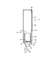
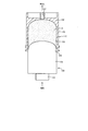
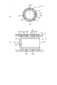
- FIG. 2 is a side sectional view showing the cartridge shown in FIG.
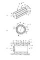
- FIG. 3 (a) is a perspective view showing the plunger shown in FIG. 1
- FIG. 3 (b) is a cross-sectional view showing the main part of the cartridge shown in FIG. 1, and a slice cross section of the cartridge.
- the spacer (or the actual portion), that is, the ridge, and the gap portion, that is, the axial continuous clearance are alternately arranged in the circumferential direction.
- FIG. 3 (c) is a cross-sectional view taken along line XX in FIG. 3 (b)
- FIG. 3 (c) is a cross-sectional view of the tip surface contacting the basic inner peripheral surface of the cylinder. It is a figure which shows having.
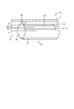
- FIG. 4 shows that when a viscous material is filled from the outside into the filling chamber (that is, the front chamber located in front of the plunger (to the left in the figure)) from the outside in the cartridge shown in FIG. Is a perspective view conceptually showing how the seal portion is formed by moving from the filling chamber to the axial continuous clearance between the plunger and the cylinder and eventually filling the axial continuous clearance with the viscous material.
- FIG. 4 shows that when a viscous material is filled from the outside into the filling chamber (that is, the front chamber located in front of the plunger (to the left in the figure)) from the outside in the cartridge shown in FIG.
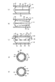
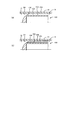
- FIG. 5A is an example of the cartridge shown in FIG. 1 and has a ridge whose width dimension does not change along the axis, that is, a spacer (or a real part) that extends in the axial direction in the same cross section.
- FIG. 5B is another example of the cartridge shown in FIG. 1 and has a ridge whose width dimension gradually changes along the axis, that is, a spacer (or a real part).
- FIG. 5C is a side view showing an axially extending section having a variable cross section, and FIG. 5C is still another example of the cartridge shown in FIG. 1, and a plurality of ridge segments are discretely arranged in a line.
- FIG. 5A is an example of the cartridge shown in FIG. 1 and has a ridge whose width dimension does not change along the axis, that is, a spacer (or a real part) that extends in the axial direction in the same cross section.
- FIG. 5B is another example of the cartridge shown in FIG.
- FIG. 5D is a side view showing a ridge, that is, a spacer having a ridge in which spacers (or real parts) and voids are alternately repeated in the axial direction
- FIG. 5D is a view of the cartridge shown in FIG.
- FIG. 5E is a cross-sectional view showing one slice cross section including a segment, that is, one spacer (or real part).
- FIG. 5E is a cross-sectional view of the single spacer (or real part) in the cartridge shown in FIG. It is sectional drawing which shows one certain slice cross-sectional part containing one space
- FIG. 6 (a) is a side view showing an example of the cartridge shown in FIG. 1 and having a ridge whose height dimension does not change along the axis
- FIG. 6 (b) is shown in FIG.
- FIG. 6 is a side view showing another example of a cartridge having a ridge whose height dimension gradually changes along an axis.
- FIG. 7 is a partial cross-sectional side view of a container set in a filling apparatus used for carrying out the filling method for filling the cartridge shown in FIG. 2 with a viscous material, in which an extrusion piston is inserted into the container. is there.
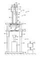
- FIG. 8 is a partial sectional front view showing the filling device.
- FIG. 9 is a partial cross-sectional side view showing the filling device.
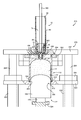
- FIG. 10 is a partial cross-sectional front view showing a main part of the filling device in a use state.
- FIG. 11 is a process diagram showing the filling method together with a viscous material manufacturing method performed prior to the filling method.
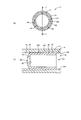
- FIG. 12A is a cross-sectional view showing a main part of a cartridge according to the second exemplary embodiment of the present invention
- FIG. 12B is a cross-sectional view taken along line YY in FIG. It is.
- FIG. 13A is a cross-sectional view showing the main part of the cartridge according to the third exemplary embodiment of the present invention
- FIG. 13B is a cross-sectional view taken along line YY in FIG. It is.
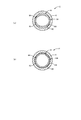
- FIG. 14A is a cross-sectional view showing a main part of a cartridge according to the fourth exemplary embodiment of the present invention
- FIG. 14B is a cross-sectional view taken along line YY in FIG. It is.
- FIG. 15A is a cross-sectional view showing the main part of the cartridge according to the fifth exemplary embodiment of the present invention
- FIG. 15B is the main part of the cartridge according to the sixth exemplary embodiment of the present invention. It is sectional drawing which shows a part.
- FIG. 1 is a partial cross-sectional side view showing a cartridge 12 according to a first exemplary embodiment of the present invention, in which a plunger 10 is fitted to a cylinder 18.
- the cartridge 12 is pre-filled with a viscous material 14 in a cylinder 18 prior to loading into a hand-held type dispenser 20 (either a gun type shown in FIG. 1 or a straight type not shown). (E.g., pressurized and the viscous material 14 is pushed into the cartridge 12 or the negative pressure causes the viscous material 14 to be sucked into the cartridge 12).
- a hand-held type dispenser 20 either a gun type shown in FIG. 1 or a straight type not shown.
- the dispenser 20 has a discharge nozzle 16 detachably attached to the tip of the cylinder 18.
- the filled cartridge 12 is detachably or interchangeably loaded into the dispenser 20.
- FIG. 1 shows the dispenser 20 in an assembled state and a used state.
- the cartridge 12 can be used alone without the dispenser 20, in which case the cartridge 12 may be referred to as a dispensing syringe. That is, the cartridge 12 can be used for an application called a dispensing syringe.
- An example of the viscous material 14 is a highly viscous and non-conductive sealant, and an example of the use of the sealant is an aircraft.
- An aircraft is a machine that requires airtightness, and a gap between the parts is filled with a sealant so that no gap remains between the parts to be assembled.
- a viscous material 14 may be used as the sealant.
- a metal (conductive) rivet is used to attach a non-conductive panel constituting the outer plate of the aircraft to the inner frame. Of these, it is driven into a through hole having a tapered portion.
- a non-conductive sealant 14 is applied on the surface of the head so that the dish-shaped head of the driven rivets is not exposed. At this point, the sealant 14 is raised from the surface of the panel. A portion of the sealant 14 protruding from the surface of the panel is shaped by being scraped off by an operator, and as a result, the surface of the sealant 14 matches the surface of the panel. Subsequently, the surfaces of the panels and the surface of the sealant 14 are painted with the same paint.
- the dispenser 20 includes a cylindrical retainer 22 and a main body portion 24 that is detachably attached to the retainer 22.
- the main body 24 includes a handle 26 held by an operator and a trigger (a lever, a switch, a button, or the like that can be relatively displaced with respect to the handle 26, and in any case, an example of an operation member) 28.
- the main body 24 further includes an air pressure control unit 30.
- the pneumatic control unit 30 has a valve 32 which is operated by a trigger 28, which valve 32 fluidly and selectively connects a chamber 33 located behind the plunger 10 and a hose connection 34. Connecting.
- a high pressure source 38 for supplying compressed gas is connected to the hose connection port 34 via a flexible hose 36.
- the valve 32 When the trigger 28 is pulled by the operator, the valve 32 is switched from the closed position to the open position. As a result, the compressed gas from the high pressure source 38 passes through the valve 32 and is introduced into the chamber (pressurized chamber) 33. . When compressed gas acts behind the plunger 10, the plunger 10 moves forward relative to the cylinder 18 (moves to the left in FIG. 1), whereby the viscous material 14 is discharged from the cylinder 18. .
- An example of the viscous material 14 is a highly viscous and non-conductive sealant, and an example of the application of the sealant is an aircraft part seal.
- the cartridge 12 is configured by fitting the plunger 10 into the cylinder 18.
- a material for the plunger 10 such as PE (polyethylene) or PP (polypropylene)
- a synthetic resin or a synthetic rubber for example, NBR
- a material called synthetic rubber is lower in rigidity than a synthetic resin such as PE or PP, and instead has higher elasticity.
- the cylinder 18 has a cylindrical inner space 70 in which the plunger 10 is detachable and substantially airtight and axially slidable. Mated.
- the cylinder 18 includes a cylindrical main body portion 60 that extends straight with a uniform cross section, and a hollow bottom portion 62 that is connected to one of both end portions of the main body portion 60.
- the bottom 62 has a cylindrical portion 64 having a smaller diameter than the main body 60 at the tip thereof, and a tapered portion 66 on the side connected to the main body 60.
- the through-hole in the cylinder part 64 is the discharge port 67 of the cylinder 18, and as shown in FIG. 1, the discharge nozzle 16 is detachably attached to the cylinder part 64 (for example, by screw connection).
- the other end of the main body 60 is an opening 68.
- An example of the material constituting the cylinder 18 is PP (polypropylene), but is not limited thereto.
- the viscous material 14 is filled from the outside (the container 112 shown in FIG. 7) into the cartridge 12 so as to pass through the discharge port 67 of the cartridge 12, and after the filling, the viscous material 14 is discharged. Therefore, the viscous material 14 is discharged from the cartridge 12 through the same passage, that is, the passage in the discharge port 67 (the passage having the smallest diameter of the cylinders 18). That is, the viscous material 14 enters and exits the cartridge 12 so as to pass through the discharge port 67 which is the smallest diameter passage.
- the internal space 70 of the cylinder 18 is filled with a filling chamber 72 (an example of the front chamber) containing the viscous material 14, which is aligned in the axial direction with each other, and the compressed gas.
- a pressurizing chamber 74 (an example of the rear chamber).
- the filling chamber 72 communicates with the discharge port 67, while the pressurizing chamber 74 is connected to the high pressure source 38 via the chamber 33 and the valve 32 as shown in FIG.
- FIG. 2 shows only the cartridge 12, but this cartridge 12 can be used alone as a dispensing syringe for dispensing the viscous material 14. That is, the cartridge 12 shown in FIG. 2 is also a dispensing syringe according to some embodiments of the present invention.
- the plunger 10 has a cylindrical main body 80 extending in the axial direction.
- the main body 80 has a coaxial outer peripheral surface 82, and the outer peripheral surface 82 of the cylinder 18 in a state where the plunger 10 is fitted to the cylinder 18 (hereinafter simply referred to as “fitted state”). It faces the inner peripheral surface 84 in the radial direction.
- the main body 80 includes a hollow peripheral wall 86 that extends in the axial direction in the same cross section, and a bottom 88 that closes one end of the peripheral wall 86.
- the main body 80 has a complete or partial solid part that extends in the axial direction in the same cross section, and a bottom formed at one end of the solid part, although not shown.
- the outer surface 90 of the bottom 88 is a curved surface (for example, a hemispherical surface) that protrudes outward but does not have a vertex.
- the outer surface 90 of the bottom 88 is a conical surface that protrudes outward and has a vertex, although not shown.
- a plurality of ridges 100 (integral to the plunger 10), each extending generally in the axial direction, are formed on the outer peripheral surface 82 of the main body 80.
- An example of the real part) and a plurality of grooves 102 (the gaps, that is, those defining the axial continuous clearance) are alternately arranged in the circumferential direction.
- a seal portion 104 is configured to seal a space between the outer peripheral surface 82 of the plunger 10 and the inner peripheral surface 84 of the cylinder 18.
- the real part functions as a spacer that defines a limit in which the plunger 10 and the cylinder 18 approach each other in the radial direction (that is, a radial interval defining member or a centering member of the plunger 10).
- the cartridge 12 can be observed as a collection of a plurality of slice cross-sectional portions arranged in a line in the axial direction.
- the slice cross sections are obtained by assuming that the cartridge 12 is sliced at any of a plurality of axial positions, for example.
- Each slice cross section has an annular portion defined by a corresponding portion of the outer peripheral surface 82 of the plunger 10 and a corresponding portion of the inner peripheral surface 84 of the cylinder 18 as shown in FIG. .
- all slice cross sections have the same shape, and each annular portion is formed of a plurality of ridges 100 (real parts or spacers) as shown in FIG.
- a plurality of grooves 102 (voids) are alternately arranged in the circumferential direction.
- the plurality of slice cross-sections include a plurality of slice cross-section pairs composed of two slice cross-sections adjacent to each other.
- the annular portion of the first slice cross-sections which is one of the two slice cross-sections belonging to each slice cross-section pair, includes a plurality of first gap portions (grooves 102).
- the annular portion of the second slice cross-sectional portion that has the plurality of first real portions (ridges 100) arranged in the circumferential direction and the other slice cross-sectional portion has a plurality of second gap portions (grooves 102). And a plurality of second existing portions (ridges 100) arranged in the circumferential direction and communicated with the plurality of first gap portions.
- the plurality of first gaps and the plurality of second gaps have the completely same phase, but as long as these gaps communicate with each other in the axial direction, It is not essential that the voids have exactly the same phase as each other.
- the plurality of first real parts and the plurality of second real parts have the same phase with each other, and the plurality of second real parts can be omitted.
- the plurality of first existing portions are adjacent to some of the plurality of second gap portions in the axial direction.
- the plurality of first gap portions and the plurality of second gap portions are adjacent to each other.
- the object of the present invention can be achieved as long as the gap communicates with the axial direction.
- the outer peripheral surface 82 of the plunger 10 and the inner peripheral surface 84 of the cylinder 18 are combined with the plurality of first gap portions and the plurality of second gap portions in the plurality of slice cross sections.
- a plurality of continuous axial clearances 106 extending at least in the direction having the axial component are formed in the same number as the number of the grooves 102. .
- Each axial continuous clearance 106 can function as a passage that allows the filling chamber 72 and the pressurizing chamber 74 to communicate with each other.
- the ridge 100 functions as the spacer, and the spacer functions not only in the original function, that is, in the function of defining the limit in which the plunger 10 and the cylinder 18 approach each other in the radial direction, but also in the axial direction. It also has a function of defining the circumferential position of the continuous clearance 106.
- each axial continuous clearance 106 functions as a passage that allows the filling chamber 72 and the pressurizing chamber 74 to communicate with each other when the viscous material 14 is not completely filled therein.
- the seal portion 104 includes an axial continuous clearance 106 filled with the part of the viscous material 14, the plurality of first real portions (the plurality of ridges 100), and the plurality of second real portions (the plurality of real portions). Formed in collaboration with Ridge 100).
- the liquid does not have its own viscosity, so that the liquid enters the axial continuous clearance 106. Then, even if the axial continuous clearance 106 flows toward the pressurizing chamber 74 through the axial continuous clearance 106 and the axial continuous clearance 106 is temporarily filled with the liquid, the liquid will remain in the axial continuous clearance 106. Do not stay in. That is, the liquid does not have self-holding properties.
- the seal part 104 is suitably formed. That is, the seal portion 104 is preferably formed by utilizing the self-holding property of the viscous material 14.
- the function of the seal portion 104 will be described.
- the seal portion 104 is formed by a subsequent portion of the viscous material 14 (for example, a portion of the viscous material 14 that is newly filled into the filling chamber 72 after the formation thereof. ), Thereby preventing subsequent portions of the filling chamber 72 from passing between the outer peripheral surface 82 of the plunger 10 and the inner peripheral surface 84 of the cylinder 18 and leaking into the pressurizing chamber 74. .
- the tip surfaces of the plurality of ridges 100 are locally in the inner peripheral surface 84 of the cylinder 18 in the fitted state, and during operation of the cartridge 12 (during filling and discharging). Medium) or during operation (dispensing) of the dispenser 20 to support the cylinder 18 in contact at least temporarily (eg, substantially always). Thereby, during operation of the dispenser 20, the posture of the plunger 10 in the cylinder 18 is stabilized.
- the fitting between the plunger 10 and the cylinder 18, that is, the radial contact state between the contact portion of the plunger 10 with the cylinder and the contact portion of the cylinder 18 with the plunger 10 is, for example, a snug fit (for example, a slip fit). Fit, dead-fit, interference fit, and fit with a fastening margin of substantially zero). This snug fit has a smaller clearance than a loose fit (for example, a clearance fit).
- the axial continuous clearance 106 is changed from the upstream region (the region on the left side of the plunger 10 in the figure) to the downstream region (the same).
- the region on the right side of the plunger 10 in the figure) is sequentially filled with a part of the viscous material 14.
- a part of the viscous material 14 mainly moves in the axial direction from the upstream side to the downstream side in each groove 102.
- a radial gap exists at least temporarily (for example, substantially always) between the front end surface of the ridge 100 and the inner peripheral surface 84 of the cylinder 18.
- a part of the viscous material 14 moves in the circumferential direction and fills the radial gap.
- a self-sealing due to the filling of the viscous material 14 is also formed between the tip surface of the ridge 100 and the inner peripheral surface 84 of the cylinder 18.
- a part of the viscous material 14 moves at least in the axial direction in the axial continuous clearance 106, so that the entire axial continuous clearance 106 is filled with a part of the viscous material 14. Is done.
- a part of the viscous material 14 filling the axial continuous clearance 106 and supplied from the filling chamber 72 leaks another part of the viscous material 14 from the filling chamber 72 to the pressurizing chamber 74.
- the axial continuous clearance 106 is at least one circumferential section of the annular portion (at the annular portion).
- the entire circumference or part of the whole part of which the axial continuous clearance 106 occupies in the first place) is substantially completely filled with the viscous material 14 (completely filled state to be described later), and its axial direction
- the shape of the plunger 10 for example, the number of the ridges 100, the shape of each ridge 100, so that the protruding amount does not exceed the prescribed amount even if the viscous material 14 that protrudes downstream of the continuous clearance 106 does not exist or exists.
- size e.g., the width and height dimensions of the ridge 100
- the surface roughness of the plunger 10 are set, respectively.
- the resistance when the viscous material 14 moves in the axial continuous clearance 106 increases, and the moving speed thereof decreases.
- the width dimension of each ridge 100 is larger (that is, the width dimension of each groove 102 is smaller)
- the resistance when the viscous material 14 moves in the axial continuous clearance 106 increases, and the movement is increased.
- the speed is reduced.
- the height dimension of the ridge 100 is smaller, the resistance when the viscous material 14 moves in the axial continuous clearance 106 increases, and the moving speed thereof decreases.
- the resistance when the viscous material 14 moves in the axial continuous clearance 106 is increased compared to a smooth surface having substantially no surface unevenness. , The moving speed is reduced.
- the fluidity in the axial continuous clearance 106 of the filled viscous material 14 is higher in the axial direction of the plunger 10 than in the absence of the axial continuous clearance 106, thereby the axial continuous clearance 106. Is filled with the viscous material 14 in the axial direction of the plunger 10.
- the unscheduled gas existing unscheduled in the filling chamber 72 passes through the unfilled portion of the axial continuous clearance 106 that is not filled with the viscous material 14. Thus, it is allowed to exit to the pressurizing chamber 74. Thereby, degassing or defoaming of the viscous material 14 filled in the filling chamber 72 is achieved.
- the leakage of the compressed gas from the pressurizing chamber 74 to the filling chamber 72 is the filling viscosity. Blocked by material 14. Thereby, unscheduled leakage of the compressed gas from the pressurizing chamber 74 is prevented.
- the plurality of ridges 100 extending in the axial direction are discretely formed on the outer peripheral surface 82 of the plunger 10 in the circumferential direction.
- a plurality of axially continuous clearances 106 that are continuous in the axial direction are formed between the outer peripheral surface 82 of the plunger 10 and the inner peripheral surface 84 of the cylinder 18.
- the axial continuous clearance 106 is filled with the part of the viscous material 14. Is done.
- the axial continuous clearance 106 filled with a part of the viscous material 14 functions as a seal portion 104 in cooperation with the plurality of ridges 100, and at this time, one of the viscous materials 14 to be filled is provided.
- the part forms the seal part 104.
- the planned air venting (that is, the degassing of the viscous material 14 in the filling chamber 72) is realized before the seal portion 104 is completed.
- unscheduled leakage of the viscous material 14 is prevented, and further, in the discharge stage of the viscous material 14, unscheduled leakage of compressed gas throughout the entire process. Is prevented.
- the plunger 10 has eight ridges 100 as shown in FIGS. 3 (a) and 3 (b). In another example, the plunger 10 has four ridges 100, as shown in FIGS. 5 (a), 5 (b), and 5 (c), respectively. In any of the examples, a plurality of ridges 100 exist in the same plunger 10, but the object of the present invention can be achieved even if only one ridge 100 exists in one plunger 10.
- the plurality of ridges 100 are discrete on the outer circumferential surface 82 at substantially equal intervals and on the entire circumference. In another example, although not shown, the number of ridges 100 is only one.
- each ridge 100 has a linear shape extending along one bus bar of the outer peripheral surface 82 of the plunger 10. That is, each ridge 100 has only a component extending in the axial direction and does not have a component extending in the circumferential direction. Further, in this example, each ridge 100 constitutes one continuous body.
- each ridge 100 has a spiral shape extending across a plurality of bus bars on the outer peripheral surface 82 of the plunger 10. That is, each ridge 100 has not only a component extending in the axial direction but also a component extending in the circumferential direction.
- the plurality of ridges 100 do not intersect with each other on the outer peripheral surface 82 of the plunger 10.
- the intersection between the ridges 100 does not exist, and if it exists, it is expected that the viscous material 14 is physically hindered by the intersection from flowing smoothly on the outer peripheral surface 82 in the axial direction.
- each of the plurality of ridges 100 has a narrower width dimension than each of the plurality of grooves 102, as shown in FIGS. 3 (a) and 3 (b).
- At least one of the plurality of ridges 100 extends over substantially all of the length dimension of the plunger 10. Yes.
- the longer each ridge 100 the smaller the maximum angle at which the plunger 10 tilts with respect to the cylinder 18, and is therefore effective in reducing the tilt angle of the plunger 10.
- At least one of the plurality of ridges 100 has a width dimension that does not change along the length of the plunger 10.
- At least one of the plurality of ridges 100 has a width dimension that increases from the filling chamber 72 toward the pressurizing chamber 74.
- the circumferential interval between the ridges 100 is smaller at the position close to the pressurizing chamber 74 than at the position close to the filling chamber 72, so The sealing ability is higher at a position near the pressurizing chamber 74 than at a position near the filling chamber 72. Therefore, according to this example, the possibility that the compressed gas leaks from the pressurizing chamber 74 to the filling chamber 72 is effectively suppressed in the discharge stage.
- At least one of the plurality of ridges 100 has a bottom surface (an outer diameter that is constant in the axial direction) of adjacent ones of the plurality of grooves 102. Having a height dimension that does not change along the length of the plunger 10.
- At least one of the plurality of ridges 100 has a height dimension from the bottom surface of the adjacent one of the plurality of grooves 102 and is filled. Some increase from the chamber 72 toward the pressurizing chamber 74.
- the example shown in FIG. 6B can be combined with the example shown in FIG.
- the minimum clearance thickness of the axial continuous clearance 106 (that is, the minimum portion of the clearance between the tip surface of the ridge 100 and the inner peripheral surface 84 of the cylinder 18).
- the thickness of the sealing portion 104 at the position close to the pressurizing chamber 74 is smaller at the position close to the pressurizing chamber 74 than at the position close to the filling chamber 72. Higher at a location closer to chamber 72. Therefore, according to this example, the possibility that the compressed gas leaks from the pressurizing chamber 74 to the filling chamber 72 is effectively suppressed in the discharge stage.
- At least one of the plurality of ridges 100 is not continuous in the axial direction, and the plurality of ridge segments 108 are axially discrete from each other. So that one ridge 100 forms a plurality of discontinuous bodies.
- the cartridge 12 has a plurality of slice cross-sections arranged in a line in the axial direction.
- Each slice cross-sectional portion has an annular portion defined by a corresponding portion of the outer peripheral surface 82 of the plunger 10 and a corresponding portion of the inner peripheral surface 84 of the cylinder 18.
- not all slice cross sections have the same shape.
- the annular portion of one slice cross section including one ridge segment 108 is shown in FIG. 5 (d).
- the plurality of first gap portions are provided together with the plurality of first actual portions (the plurality of ridges 100) arranged in the circumferential direction.
- FIG. 1 another slice cross-section adjacent to the slice cross-section in the axial direction, that is, the annular portion of the slice cross-section not including any ridge segment 108 is as shown in FIG.
- one second void portion (a plurality of grooves 102 and a plurality of depletion portions (a space between two adjacent ridge segments 108 combined with each other)) is formed in the circumferential direction. It has it in the state connected with the said several 1st space
- the outer peripheral surface 82 of the plunger 10 and the inner peripheral surface 84 of the cylinder 18 are jointly formed by the plurality of first gap portions and the plurality of second gap portions in the plurality of slice cross sections.
- one continuous axial continuous clearance 106 extending in a direction having only the axial component and the circumferential component is formed.
- the plurality of ridge segments 108 are replaced with a plurality of point-like ridges (for example, hemispherical, conical, cylindrical), and the point-like ridges are dispersed along a plurality of bus bars.
- each point-like raised portion functions as the spacer, and a portion of the annular portion excluding these point-like raised portions functions as one continuous axial continuous clearance 106.
- the axial continuous clearance 106 extends continuously both in the axial direction and in the circumferential direction.
- the plunger 10 adopts a hollow structure, and the peripheral wall portion 86 of the main body 80 is elastically deformed in the radial direction. It is easier than adopting it.
- the ridges 100 are Elastically deforms radially inward. As a result, the ridges 100 are prevented from coming into strong contact with the inner peripheral surface 84 of the cylinder 18.
- each ridge 100 is a cross section having a generally rectangular shape.
- the cross section of each ridge 100 is a cross section having other shapes, such as a cross section that tapers radially outward (generally a triangular, hemispherical or trapezoidal cross section). It is possible.
- each ridge 100 has a generally triangular, hemispherical, or trapezoidal cross section, rather than a rectangular cross section. Therefore, the radial clearance between the front end surface of each ridge 100 and the inner peripheral surface 84 of the cylinder 14 is facilitated to be filled with the viscous material 14.
- each groove 102 is a cross section having a generally rectangular shape.
- the cross-section of each groove 102 is a cross-section having another shape, such as a cross-section that tapers radially inward (generally a triangular, hemispherical or trapezoidal cross-section). It is possible.
- the cross section of each ridge 100 is a cross section that tapers radially outward, while the cross section of each groove 102 is a cross section that tapers radially inward.
- the outer peripheral surface 82 of the plunger 10 has a circular cross section while the inner peripheral surface 84 of the cylinder 18 has a circular cross section.
- the outer peripheral surface 82 of the plunger 10 has a non-circular cross section in a state where the inner peripheral surface 84 of the cylinder 18 has a circular cross section, and a plurality of ridges 100 with respect to the plurality of ridges 100 are provided. Is located on one closed line that is concentric with the plunger 10 and is non-circular (eg, oval, ellipse, polygon).
- the axial dimension representing the plunger 10 (for example, in FIG. 3C, the axial length from the edge position on the filling chamber 72 side to the edge position on the pressurizing chamber 74 side of the peripheral wall portion 86) is the same. It is longer than the dimension in the diameter direction representative of the plunger 10 (for example, in FIG. 3B, the diameter of one circumference circumscribing the silhouette obtained by projecting the plunger 10 in the axial direction). Due to such a dimensional effect, the maximum value of the angle at which the plunger 10 tilts unexpectedly by the compressed gas in the cylinder 18 when the compressed gas acts is reduced.
- the aspect ratio which is the ratio of the axial dimension representing the plunger 10 to the diametric dimension representing the same plunger 10, may be about 1 or more, about 1.2 or more, or about 1.5 or more. This is possible, and the greater the aspect ratio is, the more the tilt prevention effect of the plunger 10 in the cylinder 18 increases.
- the viscous material 14 Prior to filling the cartridge 12, the viscous material 14 is manufactured and stored in the container 112 shown in FIG. Thereafter, the viscous material 14 accommodated in the container 112 is distributed from the container 112 to the plurality of cartridges 12. The viscous material 14 in the container 112 is pushed out of the container 112 when the extrusion piston 122 is pushed into the container 112. The extruded viscous material 14 is filled in the cylinder 18.
- FIG. 7 shows the container 112 in a side sectional view.
- the same container 112 produces the viscous material 14 (two-liquid mixing described in detail later), and defoams the viscous material 14 after the production (vacuum centrifugal defoaming using a stirrer described in detail later). , Used to store and transport the viscous material 14 prior to filling the cartridge 12 and to fill the cartridge 12.
- the container 112 has a hollow housing 150 extending in the axial direction and a cylindrical chamber 152 formed coaxially in the housing 150.
- the chamber 152 has an opening 154 and a bottom 156.
- the inner surface of the bottom 156 has a concave surface that is generally hemispherical.
- the viscous material 14 flows more smoothly in the chamber 152 than when the inner surface of the bottom portion 156 is flat, and as a result, the stirring efficiency of the viscous material 14 is improved.
- An example of the material constituting the container 112 is POM (polyacetal), and another example is Teflon (registered trademark), but is not limited thereto.
- a discharge passage 157 for discharging the viscous material 14 (mixture of liquid A and liquid B) accommodated in the chamber 152 toward the cylinder 18 is formed at the bottom 156 of the chamber 152.
- the discharge passage 157 is selectively closed by a detachable plug (not shown).
- the extrusion piston 122 is pushed into the chamber 152 of the container 112 in order to discharge the viscous material 14 from the container 112.
- the extrusion piston 122 has a main body portion 158 and an engaging portion 159 formed at the rear end portion of the main body portion 158.
- the main body 158 has an outer surface shape that complements the inner surface shape of the chamber 152 of the container 112 (for example, a shape having a generally hemispherical convex portion).
- the engaging portion 159 has a smaller diameter than the main body portion 158, and an external force is applied thereto from the filling device 210 (see FIG. 10), whereby the push-out piston 122 is advanced.
- the viscous material 14 is pushed out from the discharge passage 157.
- FIG. 8 shows a filling device 210 for transferring the viscous material 14 from the container 112 to the cartridge 12 for filling
- FIG. 9 shows the filling device 210 in a partial sectional side view. Yes.
- FIG. 10 shows an enlarged partial cross-sectional front view of the main part of the filling device 210 in use.
- the container 112 when the viscous material 14 is transferred from the container 112 to the cartridge 12, the container 112 has the opening 154 of the chamber 152 facing downward, as shown in FIG. It is held in the space with the posture facing up (upside down posture). In this state, the extrusion piston 122 is raised in the chamber 152. As a result, the viscous material 14 is pushed upward from the chamber 152.
- the cartridge 12 is held in the space in such a posture that the opening 68 faces upward and the bottom 62 faces downward. In this state, the viscous material 14 pushed upward from the container 112 is injected from the bottom 62 of the cartridge 12.
- the filling device 210 has a container holder mechanism 270 that detachably holds the container 112 at a lower portion thereof, and a cartridge holder mechanism that detachably holds the cartridge 12 at an upper portion thereof. 272.
- the container holder mechanism 270 includes a base plate 280 to be installed, a top plate 282 that cannot be moved up and down positioned above the base plate 280, and both ends fixed by the base plate 280 and the top plate 282, vertically and parallel to each other.
- a plurality of extending shafts (in this embodiment, as shown in FIGS. 8 and 9, two shafts arranged symmetrically with respect to each other across the vertical center line of the container holder mechanism 270). ing.
- the top plate 282 has a through hole 290. The through hole 290 is coaxial with the vertical center line of the container holder mechanism 270.
- a guide plate 292 is fixed to the lower surface of the top plate 282.
- the guide plate 292 has a guide hole 294 that is coaxial with the through hole 290.
- the guide hole 294 penetrates the guide plate 292 with a uniform cross section in the thickness direction.
- the guide hole 294 has an inner diameter slightly larger than the outer diameter of the bottom portion 156 of the container 112, and the container 112 can be fitted into the guide hole 294 without any difficulty. is there. Thanks to this guide hole 294, the container 112 is aligned relative to the top plate 282 with respect to the position in the horizontal direction (diameter direction of the container 112).
- the container 112 in a state where the bottom 156 of the container 112 is fitted in the guide hole 294, the container 112 is placed on the lower surface of the top plate 282 at the distal end surface (on the same plane) of the bottom 156 thereof. bump into. Accordingly, the container 112 is aligned relative to the top plate 282 with respect to the position in the vertical direction (the axial direction of the container 112).
- the container holder mechanism 270 further has a movable plate 300 that can be raised and lowered.
- the movable plate 300 has a plurality of sleeves 302 that are slidably fitted to the shaft 284 in the axial direction. The operator can move the movable plate 300 to an arbitrary position in the vertical direction and stop it by operating the lock mechanism 304.
- the movable plate 300 has a stepped positioning hole 306 coaxially with the guide hole 294.
- the positioning hole 306 penetrates the movable plate 300 in the thickness direction.
- the positioning hole 306 has a large-diameter hole 310 on the side close to the guide hole 294 and a small-diameter hole 312 on the opposite side.
- the large-diameter hole 310 has an inner diameter that is slightly larger than the outer diameter of the opening 154 of the container 112, so that the container 112 is movable plate 300 (with respect to the position in the horizontal direction (diameter direction of the container 112)). As a result, it is aligned relative to the top plate 282).
- the shoulder surface 314 comes into contact with the front end surface (on the same plane) of the opening 154 of the container 112, so that the container 112 is movable with respect to the position in the vertical direction (the axial direction of the container 112). Aligned relative to the top plate 282).
- the small diameter hole 312 has an inner diameter slightly larger than the outer diameter of the extrusion piston 122, and the extrusion piston 122 is slidably fitted into the small diameter hole 312.
- the small diameter hole 312 functions as a guide hole for guiding the axial movement of the extrusion piston 122.
- a container set is configured by inserting the extrusion piston 122 into the container 112.
- the container set is set on the top plate 282 in a state where the movable plate 300 is sufficiently retracted downward from the top plate 282. . Thereafter, the movable plate 300 is raised until the front end surface of the opening 154 of the container 112 hits the shoulder surface 314. In this position, the movable plate 300 is fixed to the shaft 284. Thereby, the holding operation
- the container holder mechanism 270 further has an air cylinder 320 as an actuator coaxially with the guide hole 294.
- a rod 322 as an elevating member extends upward from the air cylinder 320, and a pusher 324 is attached to the tip of the rod 322.
- the pusher 324 engages with the engaging portion 159 of the extrusion piston 122 in the container set held by the container holder mechanism 270.
- the push-out piston 122 moves forward with respect to the container 112 and decreases the volume of the chamber 152.
- the air cylinder 320 is a double-acting type, and the pusher 324 moves forward from the initial position to the operating position (up by pressurization), retreats from the operating position to the non-operating position (down by pressurization), and any position.
- the stop at (the exhaust from both gas chambers in the air cylinder 320 is blocked) is selectively performed according to the operator's operation.
- the air cylinder 320 is connected to a high pressure source (the primary pressure is, for example, 0.2 MPa) 325b via an air pressure control unit 325a having a switching valve.
- the container holder mechanism 270 further includes a gas spring 326 as a damper.
- the gas spring 326 extends vertically and is pivotally connected to the base plate 280 and the movable plate 300 at both ends thereof.
- the gas spring 326 is installed to limit the movement of the movable plate 300 that descends by its own weight when the lock mechanism 304 is in the unlocked state.
- the cartridge holder mechanism 272 includes a base frame 330 fixed to the top plate 282, an air cylinder 332 as an actuator, a top frame 334, and a movable frame 336.
- the air cylinder 332 has a main body 340 that extends vertically and is fixed to the top plate 282 and the top frame 334, and a lifting rod 342 that is linearly moved with respect to the main body 340.
- the upper end of the lifting rod 342 (the end protruding from the main body 340) is fixed to the movable frame 336.
- the air cylinder 332 is a double-acting type, and the elevating rod 342 moves forward from the initial position to the operating position (rising by pressurization), retreats from the operating position to the non-acting position (decreasing by pressurization), arbitrary Floating at the position (both exhaust from both gas chambers in the air cylinder 332 is allowed) is selectively performed according to the operator's operation. That is, the air cylinder 332 selectively shifts to the forward mode, the reverse mode, and the floating mode.
- the air cylinder 332 is connected to the high pressure source 325a via the pneumatic control unit 325a.
- a plurality of sleeves (in this embodiment, two parallel sleeves arranged symmetrically with respect to the air cylinder 332) are fixed to the main body 340.
- a plurality of vertically extending shafts 346 are slidably fitted to the sleeves 344. All of the upper ends of the shafts 346 are fixed to the movable frame 336.
- the base frame 330, the top frame 334, the main body 340, and the sleeve 344 are stationary members, whereas the movable frame 336, the lifting rod 342, and the shaft 346 are lifted and lowered integrally with each other. It is a movable member.
- the cartridge holder mechanism 272 further includes a gas spring 350 as a damper.
- the gas spring 350 extends vertically between the base frame 330 and the movable frame 336.
- the gas spring 350 includes a cylinder 352 having a gas chamber (not shown) and a rod 354 that can be expanded and contracted with respect to the cylinder 352.
- the cylinder 352 is pivotally connected to the base frame 330 at one end thereof.
- the tip of the rod 354 is separably engaged with the lower surface of the movable frame 336. Therefore, the rod 354 may be compressed by the movable frame 336 but not expanded. The rod 354 applies an upward force to the movable frame 336 in the compressed state, thereby assisting the movable frame 336 to rise.
- the container 112 and the cartridge 12 are directly connected to each other by, for example, screwing of a male screw and a female screw, so that the cartridge 112 is held in the filling device 210 in the state where the container 112 is held by the filling device 210. 12 is aligned with respect to the container 112 in both diametrical and axial directions.
- the rod 360 is inserted into the cartridge 12 while the container set is held by the container holder mechanism 270 and the cartridge 12 is connected to the container set.
- the rod 360 is held by a cartridge holder mechanism 272.
- the cartridge holder mechanism 272 holds the rod 360, and the rod 360 is inserted into the cartridge 12, and as a result, the cartridge 12 is held by the cartridge holder mechanism 272.
- the rod 360 is configured as a tube having rigidity and extending straight.
- the rod 360 is a steel pipe (or a synthetic resin pipe), and can transmit a compressive force in the axial direction.
- the rod 360 is substantially airtightly closed by a stopper 362 at the tip end surface thereof.
- the rod 360 hits the inner surface 89 of the bottom portion 88 of the plunger 10 at the distal end surface of the stopper 362, thereby uniquely determining the approach limit of the rod 360 to the plunger 10.
- the rod 360 is fixed to the movable frame 336.
- the rod 360 extends coaxially with the vertical center line of the filling device 210 (coaxial with the center line of the guide hole 294).
- the filling device 210 aligns the cartridge 12 with respect to the position of the top plate 282.
- the viscous material 14 is a high-viscosity synthetic resin, and is cured when heated to a certain temperature (for example, 50 ° C.) or higher. Once cured, the viscous material 14 has a thermosetting property that does not restore properties even when the temperature is lowered. Have. If the viscous material 14 is not cured and is frozen below a certain temperature (for example, ⁇ 20 ° C.), the progress (curing) of the chemical reaction in the viscous material 14 stops. Thereafter, when the viscous material 14 is heated and thawed, the chemical reaction in the viscous material 14 is resumed (cured).
- a certain temperature for example, 50 ° C.
- the viscous material 14 has a thermosetting property that does not restore properties even when the temperature is lowered. Have. If the viscous material 14 is not cured and is frozen below a certain temperature (for example, ⁇ 20 ° C.), the progress (curing) of the chemical reaction in the viscous material 14 stops. Thereafter,
- the viscous material 14 is a two-liquid mixing type, and is provided by mixing two liquids of liquid A (curing agent) and liquid B (main agent).
- a liquid is PR-1776 B-2 and Part A (accelerator and manganese dioxide dispersion) of PRC-DeSoto International, USA, and an example of the B liquid combined therewith is US PRC. -PR-1776 B-2 and Part B (Desoto International Co., Ltd.) (base component and filled modified polysulfide resin).
- step S 112 in order to manufacture the viscous material 14, first, two liquids are mixed in the container 112 in step S11. Next, in step S ⁇ b> 12, stirring and defoaming is performed on the viscous material 14 accommodated in the container 112 using a stirrer (not shown). In the present embodiment, the same container 112 is used for mixing two liquids for producing the viscous material 14 and stirring and defoaming the viscous material 14 with a stirrer.
- stirrer An example of a stirrer is disclosed in Japanese Patent Application Laid-Open No. 11-104404, and the content of this publication is incorporated herein by reference in its entirety.
- this type of stirrer rotates the container 112 filled with the viscous material 14 around the rotation axis eccentric to the revolution axis while revolving around the revolution axis under vacuum pressure, Thereby, the viscous material 14 is deaerated while being stirred in the container 112.
- the viscous material 14 is stirred by the centrifugal force caused by the planetary motion by the stirrer. Further, the bubbles mixed in the viscous material 14 are discharged from the viscous material 14 due to the joint action of the centrifugal force caused by the planetary motion by the stirrer and the negative pressure caused by the vacuum atmosphere. Defoamed. Thereby, the generation of voids in the viscous material 14 is completely or sufficiently prevented.
- the viscous material 14 is mixed in the container 112 and stirred and degassed as described above, the viscous material 14 is transferred from the container 112 to the cartridge 12 using the filling device 210 as shown in FIG. Work to be started.
- step S21 the operator prepares the container set by inserting the extrusion piston 122 into the container 112 filled with the viscous material 14, as shown in FIG.
- step S22 the operator holds the container set in the filling device 210 by setting the container set upside down on the container holder mechanism 270 of the filling device 210 as shown in FIG.
- the movable plate 300 is retracted downward from the container set before the container set is held by the container holder mechanism 270.
- the operator first places the container set on the retracted movable plate 300 at a predetermined position in an upside down posture. Thereafter, the operator raises the movable plate 300 together with the container set until the container 112 hits the top plate 282. Finally, the operator fixes the movable plate 300 at that position.
- step S23 the operator prepares the cartridge 12 by inserting the plunger 10 into the cartridge 12, as shown in FIG.
- step S24 as shown in FIG. 10, the cartridge 12 is substantially airtightly connected to the container set previously held by the filling device 210 in an upside down posture, whereby the cartridge 12 is connected to the filling device 210. To hold.
- the air cylinder 332 Prior to mounting the cartridge 12 to the filling device 210, the air cylinder 332 is in the forward mode described above and pushes the lifting rod 342, so that the rod 360 is in a position retracted upward from the cartridge 12. . That is, the attachment of the cartridge 12 to the filling device 210 is not obstructed by the rod 360.
- step S25 the air cylinder 332 is switched to the above-described backward mode, and the lifting rod 342 is retracted to insert the rod 360 in the retracted position into the cartridge 12.
- the rod 360 is lowered by the air cylinder 332 until the stopper 362 of the rod 360 abuts against the plunger 10 previously present in the cartridge 12.
- the advance limit of the plunger 10 is defined, for example, by contact with the tip of the portion of the bottom 156 of the container 112 that forms the discharge passage 157.
- the air cylinder 332 is switched to the above-described floating mode.
- the rod 360 to the plunger 10 are moved together with the weight of the rod 360 and the rod 360.
- the force is a force for pressing the plunger 10 toward the bottom portion 62 of the cartridge 12 and is a force for decreasing the volume of the filling chamber 72.
- step S26 the extrusion piston 122 is raised and pushed into the container 112 as shown in FIG. Along with this, the viscous material 14 is pushed out from the container 112 against the force of gravity, whereby the filling into the filling chamber 72 is started.
- a differential pressure is generated in the cartridge 12 such that the filling chamber 72 has a higher pressure than the pressurizing chamber 74 (atmospheric pressure) communicating with the outside of the cartridge 12. Due to the differential pressure, the air in the filling chamber 72 passes through the radial clearance between the plunger 10 and the cylinder 18 (the seal portion 104 is not completed) and flows into the pressurizing chamber 74. As a result, it is discharged from the opening 68 of the cartridge 12 to the outside. Thereby, the air in the filling chamber 72 is vented.
- the pressurizing chamber 74 atmospheric pressure
- the rod 360 is applied with the force in the direction in which the volume of the filling chamber 72 decreases to the plunger 10 in the cartridge 12.
- the applied force is a force in a direction in which the plunger 10 approaches the viscous material 14 that has flowed into the cartridge 12.
- the above-described differential pressure is generated even when the force is applied by the rod 360, and a larger differential pressure is generated in the cartridge 12 than when the force is not applied by the rod 360.
- the phenomenon that the air existing in the filling chamber 72 flows into the pressurizing chamber 74 through the radial clearance between the plunger 10 and the cylinder 18 is promoted.
- the first part of the viscous material 14 in the filling chamber 72 is consumed to form the seal portion 104, and when the seal portion 104 is completed, the remaining portion of the viscous material 14 is replaced by the seal portion. 104 prevents the outflow to the pressurizing chamber 74.
- the viscous material block is performed by the seal portion 104.
- the viscous material 14 is filled into the plunger 10 not from the opening 68 thereof but from the discharge port 67, so that the plunger 10 is filled into the plunger 10 in the initial filling chamber 72 where filling is started.
- a layer of air (upper layer) is formed closer to it, and a layer of viscous material 14 is formed below the layer of air.
- the gas spring 350 shown in FIG. 9 Prior to filling the cartridge 12 with the viscous material 14, the gas spring 350 shown in FIG. 9 is compressed by the movable frame 336. As a reaction, the gas spring 350 applies a force to the movable frame 336 to raise the movable frame 336 together with the rod 360.
- step S27 the ascent of the rod 360 and the movable frame 336 is mechanically assisted by the gas spring 350.
- step S28 it is awaited that the amount of the viscous material 14 filled in the cylinder 18 reaches the specified amount, and the rod 360 rises to the specified position.
- the forward movement of the extrusion piston 122 is stopped by switching the air cylinder 320, and then the air cylinder 332 pushes the lifting rod 342 so that the plunger 10 remains in the cylinder 18, The rod 360 is raised, thereby pulling the rod 360 out of the cartridge 12.
- step S29 the operator removes the cartridge 12 from the container 112 and the filling device 210.
- step S30 the operator removes the container set from the filling device 210.
- the axial continuous clearance 106 is formed between the outer peripheral surface 82 of the plunger 10 and the inner peripheral surface 84 of the cylinder 18.
- the axial continuous clearance 106 allows the flow of gas and viscous material 14 from the filling chamber 72 toward the pressurizing chamber 74.
- the cartridge 12 has a so-called self-sealing function.
- a part of the viscous material 14 to be filled and discharged also functions as the sealing portion 104 itself. It is.
- the gas flow from the filling chamber 72 toward the pressurizing chamber 74 i.e., the scheduled time, before the seal portion 104 is completed.
- Degassing ie degassing or degassing of the viscous material 14
- the flow of the viscous material 14 from the filling chamber 72 toward the pressurizing chamber 74 that is, an unexpected leakage of the viscous material is prevented.
- the gas flow from the pressurizing chamber 74 toward the filling chamber 72 that is, unscheduled gas leakage, is prevented throughout the entire process.
- the outer peripheral surface 82 of the plunger 10 and the inner peripheral surface 84 of the cylinder 18 do not extend over the entire circumference at that position.
- only a part in the circumferential direction, that is, the actual part or the spacer has a possibility of contacting each other.
- the conventional dispenser in which the outer peripheral surface 82 of the plunger 10 and the inner peripheral surface 84 of the cylinder 18 are in contact with each other over the entire circumference. That is, the contact area in each cross section between the outer peripheral surface 82 of the plunger 10 and the inner peripheral surface 84 of the cylinder 18 is reduced by the dispenser having the circumferential land described above, and as a result, both are relatively relative to each other in the axial direction. This reduces the sliding resistance that is generated when the actuator is displaced.
- the tendency of the plunger 10 to tilt unexpectedly with respect to the cylinder 18 is suppressed, and thereby the filling chamber 72 is caused by the tilt.
- the possibility that bubbles are mixed into the viscous material 14 inside is reduced.
- the outer peripheral surface 82 of the plunger 10 and the inner peripheral surface 84 of the cylinder 18 are partially in the circumferential direction at that position. That is, in the actual part or the spacer, there is a possibility that they are in contact with each other at least temporarily (for example, substantially always). That is, as described above, the cartridge 12 adopts the snug fit as the fitting method.
- the plunger 10 is loosely fitted to the cylinder 18, so that the plunger is less frequently than the cartridge 12 according to the present embodiment. It is also conceivable to take measures to prevent the outer peripheral surface 82 of 10 and the inner peripheral surface 84 of the cylinder 18 from contacting each other.
- the plunger 10 tends to be displaced laterally in the cylinder 18 or tilted with respect to the cylinder 18 during the operation of the dispenser 20.
- the relative dynamic posture of the plunger 10 may not be stable.
- the plunger 10 and the cylinder 18 are implemented in such a manner that they can contact each other at least temporarily (for example, substantially always) via the real part or the spacer. Therefore, the plunger 10 is supported from the side by the cylinder 18 through its actual part or spacer, and as a result, the stability of the relative dynamic posture of the plunger 10 in the cylinder 18 is improved. To do.
- the continuous clearance 106 is formed not over the entire circumference of the inner peripheral surface 84 of the cylinder 18 but only over a part thereof. Therefore, according to the present embodiment, the entire volume of the continuous clearance 106, that is, the filling amount of the viscous material 14 is reduced as compared with the case of taking the above-described loose fit countermeasure.
- the amount of viscous material 14 consumed to fill the continuous clearance 106 to form the seal 104 i.e., the viscosity that may be discarded without being used for its intended use.
- the amount of material 14 is small.
- the time required to form the seal portion 104 by filling the viscous material 14 may be shortened compared with the case where the above-described measures against loose fitting are taken. That is, it is possible to complete the seal portion 104 in a shorter time, thereby improving work efficiency.
- the seal portion 104 includes the continuous clearance 106 filled with the viscous material 14 and a material (for example, the plunger 10 (or the cylinder 18)) having higher rigidity than the viscous material 14. It is configured as a rigid-soft composite structure in which a ridge 100 (or any other spacer) made of the same material as the material is arranged in the circumferential direction.
- the rigidity of the entire seal portion 104 is improved as compared with the case where the above-mentioned measures against loose fitting are taken.
- the viscous material 14 is discharged from the cartridge 12
- the possibility that the seal portion 104 is cracked by the compressed gas from the pressurizing chamber 74 or the possibility that the seal portion 104 is locally damaged is reduced.
- the pressure resistance performance of the seal portion 104 is improved.
- the possibility that the compressed gas enters the seal portion 104 unexpectedly and passes through the seal portion 104 and enters the filling chamber 72 during the discharge of the viscous material 14 is also reduced. Is done. That is, according to the present embodiment, it becomes easy to more reliably prevent the compressed gas from leaking during the discharge stage of the viscous material 14.
- each ridge 100 is shorter than the circumferential length of the adjacent axial continuous clearance 106 at each cross-sectional position of the plunger 10, but instead, at least one It is possible to implement the present invention in such a manner that the peripheral length of the ridge 100 is longer than the peripheral length of the adjacent axial continuous clearance 106.
- At least one groove is formed on the outer peripheral surface 82 of the plunger 10 in a direction having at least an axial component.
- the at least one groove forms an axial continuous clearance 106, while the outer peripheral wall portion of the plunger 10 (that is, the wall thickness of the plunger 10 is thick).
- there is no restriction that the width dimension of the spacer must be shorter than the width dimension of the axial continuous clearance 106.
- FIG. 12 (a) is a cross-sectional view showing the main part of the cartridge 12 according to the second embodiment
- FIG. 12 (b) is a cross-sectional view taken along the line YY in FIG. 12 (a).
- the plurality of actual portions or spacers are formed integrally with the plunger 10 and are radially outward from the outer peripheral surface (basic outer peripheral surface) 82 thereof.
- a plurality of protruding first members for example, a plurality of hemispherical bulges 400 are configured.
- the first members 400 are formed on the outer peripheral surface (basic outer peripheral surface) 82 of the plunger 10. It is lined up in the circumferential direction across the part.
- the first members 400 are arranged in a line in the axial direction on the outer peripheral surface 82 (basic outer peripheral surface) of the plunger 10 with a plurality of depletion portions therebetween.
- one continuous axial clearance 106 is formed in one cartridge 12, and the continuous axial clearance 106 extends in a direction having not only an axial component but also a circumferential component. Yes.
- the axial continuous clearance 106 functions as a passage that allows the filling chamber 72 and the pressurizing chamber 74 to communicate with each other.
- Each first member 400 has a tip surface that supports the cylinder 18 at least temporarily (eg, substantially always) in contact with the inner peripheral surface 84 of the cylinder 18 during operation of the dispenser 20.
- FIG. 13A is a cross-sectional view showing the main part of the cartridge 12 according to the third embodiment
- FIG. 13B is a cross-sectional view taken along line YY in FIG. 13A.
- the plurality of actual portions or spacers are formed integrally with the cylinder 18 and have an inner peripheral surface (basic inner peripheral surface).
- a plurality of second members for example, a plurality of ridges extending straight in a hemispherical cross section 500 projecting radially inward from 84 are configured.
- the second members 500 are separated from each other by a plurality of gaps, that is, a plurality of second members 500, on the inner peripheral surface (basic inner peripheral surface) 84 of the cylinder 18.
- the plurality of continuous axial clearances 106 are arranged in the circumferential direction.
- each of the second members 500 extends straight in the axial direction on the inner peripheral surface (basic inner peripheral surface) of the cylinder 18 as shown in FIG. 13B.
- a single cartridge 12 has a plurality of axial continuous clearances 106 arranged in the circumferential direction (by one second member 500 interposed between two axial continuous clearances 106 adjacent to each other, The axial continuous clearances 106 extend in a direction having only an axial component.
- Each axial continuous clearance 106 functions as a passage that allows the filling chamber 72 and the pressurizing chamber 74 to communicate with each other.
- Each second member 500 has a tip surface that supports the plunger 10 by at least temporarily (for example, substantially always) contacting the outer peripheral surface 82 of the plunger 10 during operation of the dispenser 20.
- the second members 500 can be spatially discretely arranged so as to extend not only in the axial direction but also in the circumferential direction, like the plurality of first members 400 shown in FIG.
- FIG. 14 (a) is a cross-sectional view showing the main part of the cartridge 12 according to the fourth embodiment
- FIG. 14 (b) is a cross-sectional view taken along the line YY in FIG. 14 (a).
- the plurality of actual portions or spacers are a plurality of third members 600 separated from both the plunger 10 and the cylinder 18, and the plunger 10 is arranged between the outer peripheral surface 82 of the cylinder 10 and the inner peripheral surface 84 of the cylinder 18.
- the third members 600 are formed by a plurality of gaps, that is, a plurality of third members 600 between the outer peripheral surface 82 of the plunger 10 and the inner peripheral surface 84 of the cylinder 18.
- a plurality of continuous axial clearances 106 that are separated from each other are arranged in the circumferential direction.
- Each axial continuous clearance 106 functions as a passage that allows the filling chamber 72 and the pressurizing chamber 74 to communicate with each other.
- these third members 600 are used together with a plurality of circumferentially extending spacers (that is, circumferential interval defining members), and one spacer is interposed between two third members 600 adjacent to each other, This prevents the two third members 600 adjacent to each other from approaching each other beyond the approach limit.
- each of the third members 600 extends straight in the axial direction between the outer peripheral surface 82 of the plunger 10 and the inner peripheral surface 84 of the cylinder 18 as shown in FIG.
- a single cartridge 12 has a plurality of axial continuous clearances 106 arranged in the circumferential direction (by one third member 600 interposed between two axial continuous clearances 106 adjacent to each other, The axial continuous clearances 106 extend in a direction having only an axial component.
- These third members 600 are in contact with the inner circumferential surface 84 of the cylinder 18 at least temporarily (eg, substantially always) during operation of the dispenser 20 to support the cylinder 18 and the outer circumferential surface 82 of the plunger 10. And an inner surface that supports the plunger 10 at least temporarily (eg, substantially always).
- the inner outline of the figure representing the cross section of the inner circumferential surface 84 of the cylinder 18 is a circle
- the outer circumferential surface 82 of the plunger 10 is a circle.
- the outer outline of the graphic representing the cross section is the outer periphery of an ellipse or an ellipse (an example of a closed line that is non-circular).
- the outer peripheral surface 82 of the plunger 10 contacts the inner peripheral surface 84 of the cylinder 18 at two contact points that are opposed to each other in the radial direction in each slice cross section.
- all slice cross-sections have the same shape, and each slice cross-section includes a contact portion where the outer peripheral surface 82 of the plunger 10 contacts the inner peripheral surface 84 of the cylinder 18 and a non-contact portion that does not contact.
- the “contact part” is an example of the actual part or the spacer
- the “non-contact part” is an example of the gap part.
- each slice cross-section portion in the annular portion of each slice cross-section portion, the contact portions and the non-contact portions are alternately arranged in the circumferential direction.
- a plurality of axial continuous clearances 106 are spatially discretely formed in the circumferential direction between the outer peripheral surface 82 of the plunger 10 and the inner peripheral surface 84 of the cylinder 18.
- Each axial continuous clearance 106 functions as a passage that allows the filling chamber 72 and the pressurizing chamber 74 to communicate with each other.
- the thickness dimension of the radial clearance between the outer peripheral surface 82 of the plunger 10 and the inner peripheral surface 84 of the cylinder 18 gradually increases as the contact portion approaches the non-contact portion.
- a boundary surface between the contact portion that functions as the spacer and the non-contact portion that functions as the axial continuous clearance 106 is a continuous surface that changes substantially continuously in the circumferential direction ( For example, it is configured as a curved surface). If the boundary is configured as a discontinuous surface having corners instead, the surface of the surface of the cartridge 12 after use is required when the cartridge 12 needs to be cleaned and recycled after use. There is a possibility that the viscous material 14 enters the sharp concave portion, and the efficiency of the recycling work is lowered.
- the boundary portion is configured as a continuous surface having no corner portion, even if the viscous material 14 adheres to the surface of the cartridge 12, the adhering matter can be easily removed from the cartridge. It becomes possible to wipe off the surface of 12, and it becomes easy to make recycling work efficient.
- the spacer and the axial continuous clearance 106 are substantially continuously connected to each other in the circumferential direction.
- the outer peripheral surface 82 of the plunger 10 (it is possible to replace the inner peripheral surface 84 of the cylinder 18 or add the inner peripheral surface 84 of the cylinder 18).
- the outline of the cross section is defined as a curve with two convex parts added, a curve with two concave parts, or a curve with two convex parts and two concave parts added to a concentric perfect circle Is possible.
- the outline drawn by the cross section of the outer peripheral surface 82 of the plunger 10 and / or the inner peripheral surface 84 of the cylinder 18 is moved along a concentric perfect circle while vibrating left and right in a zigzag manner. Is replaced with a wavy curve (for example, a wavy spline curve).
- three or more convex portions and three or more concave portions are alternately arranged in the circumferential direction, and the convex portions function as the spacers, respectively, while a plurality of spaces defined by the concave portions are respectively in the axial direction. It functions as a continuous clearance 106.
- the wavy curved surface as described above is formed on the outer peripheral surface 82 of the plunger 10 and the inner peripheral surface 84 of the cylinder 18 so as to complement each other.
- the convex portion of the outer peripheral surface 82 of the plunger 10 is a concave portion of the inner peripheral surface 84 of the cylinder 18, and the concave portion of the outer peripheral surface 82 of the plunger 10 is a convex portion of the inner peripheral surface 84 of the cylinder 18.
- the outer peripheral surface 82 of the plunger 10 and the inner peripheral surface 84 of the cylinder 18 are fitted so as to be slidable in the axial direction while leaving a radial clearance.
- the one that contacts the mating member functions as the spacer, and the radial gap functions as the axial continuous clearance 106.
- the plunger 10 and the cylinder 18 are axially connected to each other by the concave-convex fitting portion arranged so as to extend over the entire circumference or a part in the circumferential direction at the position of at least one cross section. It is slidably fitted in the direction.
- the plunger 10 and the cylinder 18 are prevented from rotating relative to each other around the axis during the operation of the cartridge 12, and this also stabilizes the dynamic posture of the plunger 10 in the cylinder 18.
- each of the protrusions and / or recesses has a curved outline, but in another modification, each of the protrusions and / or recesses is illustrated in FIG. As described above, a plurality of straight line segments are connected to each other to have a polygonal outline.
- the inner outline of the figure representing the cross section of the inner circumferential surface 84 of the cylinder 18 is a circle
- the outer circumferential surface 82 of the plunger 10 is a circle.
- the outer outline of the graphic representing the cross section is the outer periphery of the polygon (another example of a closed line that is non-circumferential).
- the outer peripheral surface 82 of the plunger 10 contacts the inner peripheral surface 84 of the cylinder 18 at a plurality of vertices that are opposed to each other in the radial direction in each slice cross section.
- all slice cross-sections have the same shape, and each slice cross-section includes a contact portion where the outer peripheral surface 82 of the plunger 10 contacts the inner peripheral surface 84 of the cylinder 18 and a non-contact portion that does not contact.
- the “contact part” is an example of the actual part or the spacer
- the “non-contact part” is an example of the gap part.
- the thickness dimension of the radial clearance between the outer peripheral surface 82 of the plunger 10 and the inner peripheral surface 84 of the cylinder 18 is changed from the contact portion to the non-contact portion.
- the increase gradient is gentler in the fifth embodiment.
- the elasticity of the plunger 10 can be substantially the same or different from that of the cylinder 18. In the latter case, the elasticity of the plunger 10 can be made stronger or weaker than that of the cylinder 18.
- the viscous material 14 is filled into the filling chamber 72 from the discharge port 67 in the cartridge 12, and in the process, the axial continuous clearance 106 is filled with the viscous material 14. After the seal portion 104 is formed, the viscous material 14 filled in the filling chamber 72 is discharged from the discharge port 67 by the compressed gas.
- the viscous material 14 is filled into the filling chamber 72 from the opening 68 with the discharge port 67 sealed in a state where the plunger 10 is not fitted to the cylinder 18, and then the cylinder 18.
- the viscous material 14 filled in the filling chamber 72 enters the axial continuous clearance 106, and the axial continuous clearance 106 is filled to form the seal portion 104. It is also possible to carry out the present invention in such a manner.
- dispensers 20 loaded in some of the cartridges 12 according to some of the embodiments described above are pneumatic dispensers that discharge viscous material by pressurizing the plunger 10 with compressed gas. It is possible to change to a dispenser of the form. For example, it is possible to change to a mechanical dispenser that discharges viscous material by pressurizing the plunger 10 by mechanical force, or to an electric dispenser that discharges viscous material by pressurizing the plunger 10 by an electric motor.
Landscapes
- Engineering & Computer Science (AREA)
- Mechanical Engineering (AREA)
- Coating Apparatus (AREA)
- Chemical & Material Sciences (AREA)
- Dispersion Chemistry (AREA)
- Containers And Packaging Bodies Having A Special Means To Remove Contents (AREA)
Abstract
本発明は、粘性材料ディスペンサ用カートリッジに関し、プランジャ(10)とシリンダ(18)との間に配置されるシール部(104)は、プランジャ(10)とシリンダ(18)との間にある環状空間の一部を周方向に占有する複数のスペーサ(400)と、前記複数のスペーサ(400)が配置される部分を除く部分に形成され、カートリッジ(12)内において、その軸方向成分を少なくとも含む向きに延びて充填室(72)と加圧室(74)とを互いに連通させる複数の軸方向連続クリアランス(106)とを含むように構成する。そして、粘性材料が外部から充填室(72)に充填されると、その粘性材料は複数の軸方向連続クリアランス(106)にも充填され、粘性材料が充填された複数の軸方向連続クリアランス(106)と複数のスペーサ(400)との共同により、シール部(104)が形成される。
Description
本発明は、粘性材料をディスペンシングするディスペンシング・シリンジおよび粘性材料をディスペンシングする方法に関するものであり、例えば、粘性材料を吐出するディスペンサに使用されるカートリッジに関するものである。
粘性材料を取り扱う分野が既に存在する。そのような粘性材料の用途としては、機械部品または電子部品のシーラント、封入剤、コーティング剤、グリース、樹脂組成物(例えば、エポキシ樹脂)、接着剤、電気・電子回路形成用ペースト、電子部品実装用はんだなどがある。そのような粘性材料は、例えば、航空宇宙産業や、電気・電子機器産業において使用される。
粘性材料を目標対象物に塗布するために、粘性材料を吐出するディスペンサが使用される。その一例は、機械力によるプランジャの加圧によって粘性材料を吐出する機械式ディスペンサであり、別の例は、圧縮ガスによるプランジャの加圧によって粘性材料を吐出する空圧ディスペンサであり、さらに別の例は、電動モータによるプランジャの加圧によって粘性材料を吐出する電動式ディスペンサである。
以下、従来の粘性材料ディスペンサの問題点を空圧ディスペンサを例にとり、具体的に説明するが、同様な問題点が他の形式のディスペンサ、例えば、上述の機械式ディスペンサや電動式ディスペンサにも存在することは当業者であれば容易に想像され得、また、他の方式のディスペンサ、例えば、ディスペンシング・シリンジにも存在することも当業者であれば容易に想像され得る。
一般に、空圧ディスペンサにはカートリッジが交換可能に装填され、そのカートリッジは、プランジャすなわちピストンがシリンダに嵌合されることによって構成される。その嵌合により、前記シリンダの内部空間が、前記粘性材料が外部から充填されるべき充填室(後述の「前室」の一例)と、前記圧縮ガスが外部から導入されるべき加圧室(後述の「後室」の一例)とに分離される。
この種の空圧ディスペンサを使用して粘性材料を目標対象物に向かって吐出するために、まず、その粘性材料を空圧ディスペンサのシリンダ内の充填室に充填することが必要である。その充填後、空圧ディスペンサにおいてプランジャを、加圧室内の圧縮ガスを用いて加圧することにより、粘性材料を目標対象物に向けて吐出する。
本発明者らは、従来のプランジャがシリンダに嵌合されて成る従来のカートリッジ内の充填室内に粘性材料を充填し、その充填後、そのカートリッジを空圧ディスペンサに装着してその空圧ディスペンサから粘性材料を吐出するという実験を繰返し行った。
その結果、本発明者らは、次のような知見を得た。すなわち、充填段階においては、充填室内に存在する空気がプランジャとシリンダとの間のクリアランスを通過して抜けるようにしたいという要望(予定された空気抜きすなわち粘性材料の脱気)と、その空気抜き後には、プランジャとシリンダとの間にシール部を形成し、それにより、粘性材料が充填室から加圧室に予定外に漏れてしまうことを防止したいという要望(粘性材料漏れ防止)とを同時に実現することが重要であるという知見を得たのである。
さらに、吐出段階においては、プランジャとシリンダとの間にシール部を形成し、それにより、圧縮ガスが加圧室から充填室に漏れてしまうことを防止すること(圧縮ガス漏れ防止)が重要であるという知見も得た。圧縮ガスが加圧室から充填室に予定外に漏れてしまうと、空圧ディスペンサから粘性材料が正常に吐出されないという問題や、これから吐出されるべき粘性材料を収容している充填室内に圧縮ガスが予定外に進入してその粘性材料内に気泡が混入してしまうという問題が発生する可能性がある。
上述のいくつかの要望を実現するために、本発明者らは、新たなプランジャを開発した。そのプランジャは、特許文献1に開示されている。
具体的に説明するに、このプランジャの外周面上に、それぞれ周方向に延びる少なくとも2つのランドが形成されている。それらランドは、前記充填室に近い第1ランドと、前記加圧室に近い第2ランドとを有する。その第2ランドは、第1ランドより大径であるため、第2ランドの先端面とシリンダの内周面との間に形成される半径方向クリアランスが、第1ランドの先端面とシリンダの内周面との間に形成される半径方向クリアランスより小さい。
このプランジャを前記シリンダに嵌合して空圧ディスペンサのカートリッジを構成し、そのカートリッジを用いて前記充填段階を経験すると、その当初においては、充填室内の空気が第1ランドおよび第2ランドとシリンダとの間のそれぞれのクリアランスを通過して前記加圧室内に抜ける。
その空気抜け(すなわち、粘性材料の脱気)が終了すると、充填室内の粘性材料の一部が、プランジャとシリンダとの間の、第1ランドより上流側の半径方向クリアランスを通過して第1ランドに到達し、それにより、その第1ランドとシリンダとの間の第1シール部が完成する。充填される対象である粘性材料の一部が第1シール部を形成するのである。
やがて、粘性材料の別の一部が第2ランドに到達し、それにより、その第2ランドとシリンダとの間の第2シール部が完成する。充填される対象である粘性材料の別の一部が第2シール部を形成するのである。前記充填工程においては、それら第1シール部および第2シール部の双方が完成した後、粘性材料が充填室から加圧室に漏れてしまうことが防止される。
後続する吐出段階においては、その当初から、第1シール部も第2シール部も完成している。したがって、加圧室内に圧縮ガスが導入されると、その圧縮ガスが第2シール部によって遮断される。よって、加圧室からの圧縮ガスが充填室に漏れてしまうことが防止される。
本発明者らは、このプランジャを用いて実験を繰り返し、その結果、次のような新たな知見を得た。
すなわち、このプランジャの吐出段階においては、圧縮ガスが外部から、プランジャの背後に位置する加圧室に導入される。その結果、プランジャの背圧が充填室の圧力に対して急に上昇し、そのプランジャに推力が発生する。その推力のおかげでプランジャが充填室に向かって前進する結果、充填室から粘性材料が外部に吐出される。
理想的には、前記背圧が、プランジャをシリンダに対して傾倒させようとする向きのモーメントすなわちこじりモーメントがプランジャに発生しないようにプランジャに作用するように、プランジャに圧縮ガスを作用させることが重要である。
なぜなら、そのようなこじりモーメントが発生すると、プランジャがシリンダに対して傾倒してしまい、その結果、プランジャがある部位においては半径方向外向きに変位してシリンダの内周面に強く接触する一方、別の部位においては半径方向内向きに変位してシリンダの内周面から離間する傾向が発生するからである。
プランジャがシリンダの内周面から局部的に離間すると、プランジャとシリンダとの間の半径方向クリアランスが局部的に拡大し、その拡大部分を充填する粘性材料に局部的に亀裂が発生する。その亀裂に圧縮ガスが加圧室から進入すると、その亀裂が軸方向に拡大し、最悪の場合には、それを契機として、加圧室と充填室とを互いに連通させる予定外の通路が形成されてしまう。その通路は、これから吐出されるべき粘性材料であって充填室に充填されているものに圧縮ガスを予定外に導入し、その結果、粘性材料に気泡が混入してしまう。
しかし、実際には、プランジャに前記こじりモーメントが全く発生しないように前記背圧がプランジャに作用するようにプランジャを作動させることは不可能である。
それらの知見に基づき、本発明は、種類の如何を問わず、粘性材料を吐出する粘性材料ディスペンサに交換可能に装填されるカートリッジであって、そのカートリッジからの粘性材料の吐出段階において、プランジャがシリンダに対して予定外に傾倒する傾向を抑制し、それにより、その傾倒が原因で充填室内の粘性材料に気泡が混入してしまう可能性を軽減するものを提供することを課題としてなされたものである。
本発明によって下記の各態様が得られる。各態様は、項に区分し、各項には番号を付し、必要に応じて他の項の番号を引用する形式で記載する。これは、本発明が採用し得る技術的特徴の一部およびそれの組合せの理解を容易にするためであり、本発明が採用し得る技術的特徴およびそれの組合せが以下の態様に限定されると解釈すべきではない。すなわち、下記の態様には記載されていないが本明細書には記載されている技術的特徴を本発明の技術的特徴として適宜抽出して採用することは妨げられないと解釈すべきなのである。
さらに、各項を他の項の番号を引用する形式で記載することが必ずしも、各項に記載の技術的特徴を他の項に記載の技術的特徴から分離させて独立させることを妨げることを意味するわけではなく、各項に記載の技術的特徴をその性質に応じて適宜独立させることが可能であると解釈すべきである。
態様(1) 粘性材料を吐出するディスペンサに使用されるカートリッジであって、
シリンダと、
そのシリンダに軸方向にスライド可能に嵌合されるプランジャと、
そのプランジャが前記シリンダに嵌合された状態において、前記プランジャより前方に形成される前室であって、前記粘性材料が外部から充填されるべき充填室として作用するもの、および、前記プランジャの背後に形成される後室と、
前記シリンダの内周面と前記プランジャの外周面との間に配置されるシール部と
を含み、
そのシール部は、
前記プランジャの外周面と前記シリンダの内周面との間の環状空間を、当該カートリッジのうちの少なくとも一つの断面の位置において、全周にわたってではなく、一部のみにわたって周方向に占有するように配置された少なくとも1つの実在部としてのスペーサであって、当該カートリッジの作動中、前記プランジャの外周面と前記シリンダの内周面とが接近限度を超えて相互に半径方向に接近することを阻止するものと、
前記環状空間のうち、前記少なくとも1つのスペーサが配置される部分を除く部分に形成され、当該カートリッジ内において、それの軸方向成分を少なくとも含む向きに延びて前記前室と前記後室とを互いに連通させる軸方向連続クリアランスと
を含み、
前記粘性材料が外部から前記充填室に充填されると、その粘性材料によって前記軸方向連続クリアランスが充填され、その充填された軸方向連続クリアランスと前記少なくとも1つのスペーサとの共同により、前記シール部が形成される粘性材料ディスペンサ用カートリッジ。
シリンダと、
そのシリンダに軸方向にスライド可能に嵌合されるプランジャと、
そのプランジャが前記シリンダに嵌合された状態において、前記プランジャより前方に形成される前室であって、前記粘性材料が外部から充填されるべき充填室として作用するもの、および、前記プランジャの背後に形成される後室と、
前記シリンダの内周面と前記プランジャの外周面との間に配置されるシール部と
を含み、
そのシール部は、
前記プランジャの外周面と前記シリンダの内周面との間の環状空間を、当該カートリッジのうちの少なくとも一つの断面の位置において、全周にわたってではなく、一部のみにわたって周方向に占有するように配置された少なくとも1つの実在部としてのスペーサであって、当該カートリッジの作動中、前記プランジャの外周面と前記シリンダの内周面とが接近限度を超えて相互に半径方向に接近することを阻止するものと、
前記環状空間のうち、前記少なくとも1つのスペーサが配置される部分を除く部分に形成され、当該カートリッジ内において、それの軸方向成分を少なくとも含む向きに延びて前記前室と前記後室とを互いに連通させる軸方向連続クリアランスと
を含み、
前記粘性材料が外部から前記充填室に充填されると、その粘性材料によって前記軸方向連続クリアランスが充填され、その充填された軸方向連続クリアランスと前記少なくとも1つのスペーサとの共同により、前記シール部が形成される粘性材料ディスペンサ用カートリッジ。
態様(2) 前記少なくとも1つのスペーサは、前記プランジャに一体的に形成されるとともに、そのプランジャの外周面から半径方向外向きに突出する第1部材を含む態様(1)に記載の粘性材料ディスペンサ用カートリッジ。
態様(3) 前記第1部材は、当該カートリッジの作動中、前記シリンダの内周面に少なくとも一時的に接触して前記シリンダを支持する先端面を有する態様(2)に記載の粘性材料ディスペンサ用カートリッジ。
態様(4) 前記少なくとも1つのスペーサは、前記シリンダに一体的に形成されるとともに、そのシリンダの内周面から半径方向内向きに突出する第2部材を含む態様(1)ないし(3)のいずれかに記載の粘性材料ディスペンサ用カートリッジ。
態様(5) 前記第2部材は、当該カートリッジの作動中、前記プランジャの外周面に少なくとも一時的に接触して前記プランジャを支持する先端面を有する態様(4)に記載の粘性材料ディスペンサ用カートリッジ。
態様(6) 前記少なくとも1つのスペーサは、前記プランジャおよび前記シリンダの双方から分離した第3部材であって、前記プランジャの外周面と前記シリンダの内周面との間に配置されるものを含む態様(1)ないし(5)のいずれかに記載の粘性材料ディスペンサ用カートリッジ。
態様(7) 前記第3部材は、当該カートリッジの作動中、前記シリンダの内周面に少なくとも一時的に接触して前記シリンダを支持する外面と、前記プランジャの外周面に少なくとも一時的に接触して前記プランジャを支持する内面とを有する態様(6)に記載の粘性材料ディスペンサ用カートリッジ。
態様(8) 前記ディスペンサは、圧縮ガスを前記プランジャにそれの背後から作用させることによって前記粘性材料を前記充填室から前方に吐出する空圧ディスペンサであり、
前記後室は、前記圧縮ガスが外部から導入されるべき加圧室として作用する態様(1)ないし(7)のいずれかに記載の粘性材料ディスペンサ用カートリッジ。
前記後室は、前記圧縮ガスが外部から導入されるべき加圧室として作用する態様(1)ないし(7)のいずれかに記載の粘性材料ディスペンサ用カートリッジ。
態様(9) 前記少なくとも1つのスペーサと前記軸方向連続クリアランスとは、周方向と軸方向とのうちの少なくとも一方の方向に実質的に連続的に向きが変化する連続面または曲面を介して互いに接続される態様(1)ないし(8)のいずれかに記載の粘性材料ディスペンサ用カートリッジ。
態様(10) 粘性材料をディスペンシングするためのシリンジであって、
シリンダと、
そのシリンダに軸方向にスライド可能に嵌合されるプランジャと、
そのプランジャが前記シリンダに嵌合された状態において、前記プランジャより前方に形成される前室であって、前記粘性材料が外部から充填されるべき充填室として作用するもの、および、前記プランジャの背後に形成される後室と、
前記シリンダの内周面と前記プランジャの外周面との間に配置されるシール部と
を含み、
そのシール部は、
前記プランジャの外周面と前記シリンダの内周面との間の環状空間を、当該シリンジのうちの少なくとも一つの断面の位置において、全周にわたってではなく、一部のみにわたって周方向に占有するように配置された少なくとも1つの実在部としてのスペーサであって、当該シリンジの作動中、前記プランジャの外周面と前記シリンダの内周面とが接近限度を超えて相互に半径方向に接近することを阻止するものと、
前記環状空間のうち、前記少なくとも1つのスペーサが配置される部分を除く部分に形成され、当該シリンジ内において、それの軸方向成分を少なくとも含む向きに延びて前記前室と前記後室とを互いに連通させる軸方向連続クリアランスと
を含み、
前記粘性材料が外部から前記充填室に充填されると、その粘性材料によって前記軸方向連続クリアランスが充填され、その充填された軸方向連続クリアランスと前記少なくとも1つのスペーサとの共同により、前記シール部が形成される粘性材料ディスペンシング・シリンジ。
シリンダと、
そのシリンダに軸方向にスライド可能に嵌合されるプランジャと、
そのプランジャが前記シリンダに嵌合された状態において、前記プランジャより前方に形成される前室であって、前記粘性材料が外部から充填されるべき充填室として作用するもの、および、前記プランジャの背後に形成される後室と、
前記シリンダの内周面と前記プランジャの外周面との間に配置されるシール部と
を含み、
そのシール部は、
前記プランジャの外周面と前記シリンダの内周面との間の環状空間を、当該シリンジのうちの少なくとも一つの断面の位置において、全周にわたってではなく、一部のみにわたって周方向に占有するように配置された少なくとも1つの実在部としてのスペーサであって、当該シリンジの作動中、前記プランジャの外周面と前記シリンダの内周面とが接近限度を超えて相互に半径方向に接近することを阻止するものと、
前記環状空間のうち、前記少なくとも1つのスペーサが配置される部分を除く部分に形成され、当該シリンジ内において、それの軸方向成分を少なくとも含む向きに延びて前記前室と前記後室とを互いに連通させる軸方向連続クリアランスと
を含み、
前記粘性材料が外部から前記充填室に充填されると、その粘性材料によって前記軸方向連続クリアランスが充填され、その充填された軸方向連続クリアランスと前記少なくとも1つのスペーサとの共同により、前記シール部が形成される粘性材料ディスペンシング・シリンジ。
本発明によれば、さらに、次のようないくつかの態様も得られる。
(1) 粘性材料を吐出するディスペンサに使用されるカートリッジであって、
軸方向に延びる内周面を有するシリンダと、
軸方向に延びる外周面を有するプランジャであって、前記シリンダに同軸にかつ軸方向にスライド可能に嵌合されるものと、
そのプランジャが前記シリンダ内に嵌合された嵌合状態において、前記シリンダの内部空間内に、かつ、前記プランジャより前方に位置する前室であって、前記粘性材料が外部から充填されるべき充填室として作用するものと、
前記嵌合状態において、前記シリンダの内部空間内に、かつ、前記プランジャの背後に位置する後室と、
前記プランジャの外周面と前記シリンダの内周面との間に形成されるシール部と
を含み、
当該カートリッジが、軸方向に一列に並んだ複数のスライス断面部の集まりとして観察される場合に、それらスライス断面部の各々は、前記プランジャの外周面のうち対応する部分と、前記シリンダの内周面のうち対応する部分とによって画定される環状部を有し、
前記複数のスライス断面部は、互いに隣接した2つのスライス断面部より成るスライス断面部対を複数有し、
いずれのスライス断面部対も、各スライス断面部対に属する2つのスライス断面部の一方である第1スライス断面部のうちの前記環状部は、少なくとも1つの第1空隙部を、それと周方向に並んだ少なくとも1つの第1実在部と共に有し、他方のスライス断面部である第2スライス断面部のうちの前記環状部は、少なくとも1つの第2空隙部を、それと周方向に並んだ少なくとも1つの第2実在部の有無を問わず、前記少なくとも1つの第1空隙部と連通する状態で有し、
前記複数のスライス断面部における前記少なくとも1つの第1空隙部と前記少なくとも1つの第2空隙部との共同により、前記プランジャの外周面と前記シリンダの内周面との間に、少なくとも軸方向成分を有する向きに延びる軸方向連続クリアランスが形成され、
前記粘性材料が外部から前記充填室に充填されると、その充填された前記粘性材料の一部が前記軸方向連続クリアランス内に進入してその軸方向連続クリアランス内を前記後室に向かって流動し、それにより、前記軸方向連続クリアランスが前記粘性材料によって充填され、
前記シール部は、前記一部の粘性材料で充填された前記軸方向連続クリアランスと、前記少なくとも1つの第1実在部と、存在する前記少なくとも1つの第2実在部との共同により、形成され、
そのシール部は、それが形成された後、前記粘性材料のうち後続する部分をブロックし、それにより、その後続する部分が前記充填室から、前記プランジャの外周面と前記シリンダの内周面との間を通過して、前記後室内に漏れることを阻止する粘性材料ディスペンサ用カートリッジ。
軸方向に延びる内周面を有するシリンダと、
軸方向に延びる外周面を有するプランジャであって、前記シリンダに同軸にかつ軸方向にスライド可能に嵌合されるものと、
そのプランジャが前記シリンダ内に嵌合された嵌合状態において、前記シリンダの内部空間内に、かつ、前記プランジャより前方に位置する前室であって、前記粘性材料が外部から充填されるべき充填室として作用するものと、
前記嵌合状態において、前記シリンダの内部空間内に、かつ、前記プランジャの背後に位置する後室と、
前記プランジャの外周面と前記シリンダの内周面との間に形成されるシール部と
を含み、
当該カートリッジが、軸方向に一列に並んだ複数のスライス断面部の集まりとして観察される場合に、それらスライス断面部の各々は、前記プランジャの外周面のうち対応する部分と、前記シリンダの内周面のうち対応する部分とによって画定される環状部を有し、
前記複数のスライス断面部は、互いに隣接した2つのスライス断面部より成るスライス断面部対を複数有し、
いずれのスライス断面部対も、各スライス断面部対に属する2つのスライス断面部の一方である第1スライス断面部のうちの前記環状部は、少なくとも1つの第1空隙部を、それと周方向に並んだ少なくとも1つの第1実在部と共に有し、他方のスライス断面部である第2スライス断面部のうちの前記環状部は、少なくとも1つの第2空隙部を、それと周方向に並んだ少なくとも1つの第2実在部の有無を問わず、前記少なくとも1つの第1空隙部と連通する状態で有し、
前記複数のスライス断面部における前記少なくとも1つの第1空隙部と前記少なくとも1つの第2空隙部との共同により、前記プランジャの外周面と前記シリンダの内周面との間に、少なくとも軸方向成分を有する向きに延びる軸方向連続クリアランスが形成され、
前記粘性材料が外部から前記充填室に充填されると、その充填された前記粘性材料の一部が前記軸方向連続クリアランス内に進入してその軸方向連続クリアランス内を前記後室に向かって流動し、それにより、前記軸方向連続クリアランスが前記粘性材料によって充填され、
前記シール部は、前記一部の粘性材料で充填された前記軸方向連続クリアランスと、前記少なくとも1つの第1実在部と、存在する前記少なくとも1つの第2実在部との共同により、形成され、
そのシール部は、それが形成された後、前記粘性材料のうち後続する部分をブロックし、それにより、その後続する部分が前記充填室から、前記プランジャの外周面と前記シリンダの内周面との間を通過して、前記後室内に漏れることを阻止する粘性材料ディスペンサ用カートリッジ。
(2) 前記粘性材料が外部から前記充填室内に充填される充填工程においては、前記粘性材料の一部が前記充填室から前記軸方向連続クリアランス内に進入し、それにより、その軸方向連続クリアランスが前記一部の粘性材料によって充填され、
前記軸方向連続クリアランスが、それの少なくとも1つの軸方向位置において、その軸方向連続クリアランスの周方向の全体にわたり、前記粘性材料によって充填される完全充填状態においては、前記一部の粘性材料自身が、前記粘性材料のうち後続する部分をブロックし、それにより、その後続する部分が前記充填室から前記後室に漏れることを阻止し、
その完全充填状態に移行する前の不完全充填状態においては、前記充填室内に予定外に存在する予定外ガスが前記軸方向連続クリアランスのうち前記充填粘性材料によって充填されていない未充填部分を通過して前記後室に抜けることが許可される(1)項に記載の粘性材料ディスペンサ用カートリッジ。
前記軸方向連続クリアランスが、それの少なくとも1つの軸方向位置において、その軸方向連続クリアランスの周方向の全体にわたり、前記粘性材料によって充填される完全充填状態においては、前記一部の粘性材料自身が、前記粘性材料のうち後続する部分をブロックし、それにより、その後続する部分が前記充填室から前記後室に漏れることを阻止し、
その完全充填状態に移行する前の不完全充填状態においては、前記充填室内に予定外に存在する予定外ガスが前記軸方向連続クリアランスのうち前記充填粘性材料によって充填されていない未充填部分を通過して前記後室に抜けることが許可される(1)項に記載の粘性材料ディスペンサ用カートリッジ。
(3) 前記軸方向連続クリアランスの厚さ寸法は、前記プランジャが前記シリンダに実質的ながたなく軸方向にスライド可能に嵌合されるために必要な厚さ寸法を下限値とし、前記充填室から前記粘性材料が外部に吐出される吐出工程の実質的な最終段階において、前記軸方向連続クリアランスをそれの軸方向の実質的な全体にわたり前記粘性材料によって充填するのに必要な厚さ寸法を上限値とするように設定される(1)または(2)項に記載の粘性材料ディスペンサ用カートリッジ。
(4) 前記第1実在部または前記第2実在部は、前記プランジャに一体的に形成されるとともに、そのプランジャの外周面から半径方向外向きに突出する第1部材を含む(1)ないし(3)項のいずれかに記載の粘性材料ディスペンサ用カートリッジ。
(5) 前記第1部材は、前記ディスペンサの作動中、前記シリンダの内周面に少なくとも一時的に接触して前記シリンダを支持する先端面を有する(4)項に記載の粘性材料ディスペンサ用カートリッジ。
(6) 前記第1実在部または前記第2実在部は、前記シリンダに一体的に形成されるとともに、そのシリンダの内周面から半径方向内向きに突出する第2部材を含む(1)ないし(5)項のいずれかに記載の粘性材料ディスペンサ用カートリッジ。
(7) 前記第2部材は、前記ディスペンサの作動中、前記プランジャの外周面に少なくとも一時的に接触して前記プランジャを支持する先端面を有する(6)項に記載の粘性材料ディスペンサ用カートリッジ。
(8) 前記第1実在部または前記第2実在部は、前記プランジャおよび前記シリンダの双方から分離した第3部材であって、前記プランジャの外周面と前記シリンダの内周面との間に配置されるものを含む(1)ないし(7)項のいずれかに記載の粘性材料ディスペンサ用カートリッジ。
(9) 前記第3部材は、前記ディスペンサの作動中、前記シリンダの内周面に少なくとも一時的に接触して前記シリンダを支持する外面と、前記プランジャの外周面に少なくとも一時的に接触して前記プランジャを支持する内面とを有する(8)項に記載の粘性材料ディスペンサ用カートリッジ。
(10) 各スライス断面部対に存在する前記第1実在部および前記第2実在部は、互いに空間的に連続して配置され、それにより、当該カートリッジの軸線に沿って概して直線的にまたはらせん状に延びる少なくとも1本の連続体を構成する(1)ないし(9)項のいずれかに記載の粘性材料ディスペンサ用カートリッジ。
(11) 各スライス断面部対に前記第2実在部が存在しないか、または、各スライス断面部対に前記第2実在部が存在するがその第2実在部は前記第1実在部に空間的に連続しないように配置され、それにより、前記複数のスライス断面部に存在する複数の第1実在部または前記複数のスライス断面部に存在する第1実在部と第2実在部との組合せは、互いに空間的に離散して配置され、それにより、複数の不連続体を構成する(1)ないし(9)項のいずれかに記載の粘性材料ディスペンサ用カートリッジ。
(12) 前記ディスペンサは、圧縮ガスを前記プランジャにそれの背後から作用させることによって前記粘性材料を前記充填室から前方に吐出する空圧ディスペンサであり、
前記後室は、前記圧縮ガスが外部から導入されるべき加圧室として作用する(1)ないし(11)項のいずれかに記載の粘性材料ディスペンサ用カートリッジ。
前記後室は、前記圧縮ガスが外部から導入されるべき加圧室として作用する(1)ないし(11)項のいずれかに記載の粘性材料ディスペンサ用カートリッジ。
(13) 粘性材料をシーラントとして目標対象物に塗布する方法であって、
前記態様(1)ないし(10)のいずれか、または、(1)ないし(12)項のいずれかに記載のカートリッジに前記粘性材料を充填し、それにより、前記カートリッジを準備する工程と、
その準備されたカートリッジを前記ディスペンサに装填する工程と、
そのディスペンサを作動させることにより、前記粘性材料をシーラントとして目標対象物に塗布する工程と
を含むシーラント塗布方法。
前記態様(1)ないし(10)のいずれか、または、(1)ないし(12)項のいずれかに記載のカートリッジに前記粘性材料を充填し、それにより、前記カートリッジを準備する工程と、
その準備されたカートリッジを前記ディスペンサに装填する工程と、
そのディスペンサを作動させることにより、前記粘性材料をシーラントとして目標対象物に塗布する工程と
を含むシーラント塗布方法。
(14) 組付け後に部品間の気密性が要求される航空機を製造する方法であって、
前記態様(1)ないし(10)のいずれか、または、(1)ないし(12)項のいずれかに記載のカートリッジに前記粘性材料を充填し、それにより、前記カートリッジを準備する工程と、
その準備されたカートリッジを前記ディスペンサに装填する工程と、
そのディスペンサを作動させることにより、前記粘性材料をシーラントとして、前記航空機の複数の部品間の隙間に塗布することにより、その隙間を充填する工程と
を含む航空機製造方法。
前記態様(1)ないし(10)のいずれか、または、(1)ないし(12)項のいずれかに記載のカートリッジに前記粘性材料を充填し、それにより、前記カートリッジを準備する工程と、
その準備されたカートリッジを前記ディスペンサに装填する工程と、
そのディスペンサを作動させることにより、前記粘性材料をシーラントとして、前記航空機の複数の部品間の隙間に塗布することにより、その隙間を充填する工程と
を含む航空機製造方法。
(15) 粘性材料を吐出するディスペンサに使用されるカートリッジであって、
シリンダと、
そのシリンダに軸方向にスライド可能に嵌合されるプランジャと、
それらシリンダとプランジャとの間に配置されるシール部と
を含み、
当該カートリッジが、複数のスライス断面部の集まりとして観察される場合に、各スライス断面部は、前記プランジャの外周面と前記シリンダの内周面とによって画定される環状部を有し、
互いに隣接した2つのスライス断面部の一方のうちの前記環状部は、第1空隙部と第1実在部とを有し、他方のスライス断面部のうちの前記環状部は、第2空隙部を前記第1空隙部と連通する状態で有し、
それら第1空隙部と第2空隙部との共同により、前記プランジャの外周面と前記シリンダの内周面との間に軸方向連続クリアランスが形成され、
前記粘性材料が外部から当該カートリッジに充填されると、その粘性材料によって前記軸方向連続クリアランスが充填され、その充填された軸方向連続クリアランスと前記第1実在部との共同により、前記シール部が形成される粘性材料ディスペンサ用カートリッジ。
シリンダと、
そのシリンダに軸方向にスライド可能に嵌合されるプランジャと、
それらシリンダとプランジャとの間に配置されるシール部と
を含み、
当該カートリッジが、複数のスライス断面部の集まりとして観察される場合に、各スライス断面部は、前記プランジャの外周面と前記シリンダの内周面とによって画定される環状部を有し、
互いに隣接した2つのスライス断面部の一方のうちの前記環状部は、第1空隙部と第1実在部とを有し、他方のスライス断面部のうちの前記環状部は、第2空隙部を前記第1空隙部と連通する状態で有し、
それら第1空隙部と第2空隙部との共同により、前記プランジャの外周面と前記シリンダの内周面との間に軸方向連続クリアランスが形成され、
前記粘性材料が外部から当該カートリッジに充填されると、その粘性材料によって前記軸方向連続クリアランスが充填され、その充填された軸方向連続クリアランスと前記第1実在部との共同により、前記シール部が形成される粘性材料ディスペンサ用カートリッジ。
(16) 粘性材料を吐出するディスペンサに使用されるカートリッジであって、
シリンダと、
そのシリンダに軸方向にスライド可能に嵌合されるプランジャと、
そのプランジャが前記シリンダに嵌合された状態において、前記プランジャより前方に形成される前室であって、前記粘性材料が外部から充填されるべき充填室として作用するもの、および、前記プランジャの背後に形成される後室と、
前記シリンダの内周面と前記プランジャの外周面との間に配置されるシール部と
を含み、
そのシール部は、
前記プランジャの外周面と前記シリンダの内周面との間の環状空間を、当該カートリッジのうちの少なくとも一つの断面の位置において、全周にわたってではなく、一部のみにわたって周方向に占有するように配置された複数の実在部としての複数のスペーサであって、当該カートリッジの作動中、前記プランジャの外周面と前記シリンダの内周面とが接近限度を超えて相互に半径方向に接近することを阻止するものと、
前記環状空間のうち、前記複数のスペーサが配置される複数の部分を除く複数の部分に形成され、当該カートリッジ内において、それの軸方向成分を少なくとも含む向きに延びて前記前室と前記後室とを互いに連通させる複数の軸方向連続クリアランスであって周方向に互いに分離しているものと
を含み、
前記複数のスペーサは、前記プランジャの外周面にその外周面から半径方向外向きに突出するように一体的に形成されるか、または前記シリンダの内周面にその内周面から半径方向内向きに突出するように一体的に形成され、
前記複数のスペーサは、前記プランジャの外周面に一体的に形成される場合には、それぞれのスペーサの先端面において前記シリンダの内周面に接触してその内周面を側方から支持し、それにより、前記プランジャと前記シリンダとのスナグフィットを前記複数のスペーサの位置においてのみ実現し、それにより、前記プランジャに対して前記シリンダをセンタリングしつつ前記複数の軸方向連続クリアランスを確保し、
前記複数のスペーサは、前記シリンダの内周面に一体的に形成される場合には、それぞれのスペーサの先端面において前記プランジャの外周面に接触してその外周面を側方から支持し、それにより、前記プランジャと前記シリンダとのスナグフィットを前記複数のスペーサの位置においてのみ実現し、それにより、前記シリンダに対して前記プランジャをセンタリングし、
前記粘性材料が外部から前記充填室に充填されると、その粘性材料によって前記複数の軸方向連続クリアランスが充填され、その充填された複数の軸方向連続クリアランスと前記複数のスペーサとの共同により、前記シール部が形成され、
前記複数のスペーサは、前記粘性材料が前記複数の軸方向連続クリアランス内を移動する際の抵抗を発生させ、その発生させられた抵抗により、前記充填室への前記粘性材料の充填の終了時点で、前記複数の軸方向連続クリアランスが、当該カートリッジのうちの少なくとも一つの断面の位置において、前記粘性材料によって充填され、かつ、前記粘性材料が前記複数の軸方向連続クリアランスから前記後室に漏れない粘性材料ディスペンサ用カートリッジ。
シリンダと、
そのシリンダに軸方向にスライド可能に嵌合されるプランジャと、
そのプランジャが前記シリンダに嵌合された状態において、前記プランジャより前方に形成される前室であって、前記粘性材料が外部から充填されるべき充填室として作用するもの、および、前記プランジャの背後に形成される後室と、
前記シリンダの内周面と前記プランジャの外周面との間に配置されるシール部と
を含み、
そのシール部は、
前記プランジャの外周面と前記シリンダの内周面との間の環状空間を、当該カートリッジのうちの少なくとも一つの断面の位置において、全周にわたってではなく、一部のみにわたって周方向に占有するように配置された複数の実在部としての複数のスペーサであって、当該カートリッジの作動中、前記プランジャの外周面と前記シリンダの内周面とが接近限度を超えて相互に半径方向に接近することを阻止するものと、
前記環状空間のうち、前記複数のスペーサが配置される複数の部分を除く複数の部分に形成され、当該カートリッジ内において、それの軸方向成分を少なくとも含む向きに延びて前記前室と前記後室とを互いに連通させる複数の軸方向連続クリアランスであって周方向に互いに分離しているものと
を含み、
前記複数のスペーサは、前記プランジャの外周面にその外周面から半径方向外向きに突出するように一体的に形成されるか、または前記シリンダの内周面にその内周面から半径方向内向きに突出するように一体的に形成され、
前記複数のスペーサは、前記プランジャの外周面に一体的に形成される場合には、それぞれのスペーサの先端面において前記シリンダの内周面に接触してその内周面を側方から支持し、それにより、前記プランジャと前記シリンダとのスナグフィットを前記複数のスペーサの位置においてのみ実現し、それにより、前記プランジャに対して前記シリンダをセンタリングしつつ前記複数の軸方向連続クリアランスを確保し、
前記複数のスペーサは、前記シリンダの内周面に一体的に形成される場合には、それぞれのスペーサの先端面において前記プランジャの外周面に接触してその外周面を側方から支持し、それにより、前記プランジャと前記シリンダとのスナグフィットを前記複数のスペーサの位置においてのみ実現し、それにより、前記シリンダに対して前記プランジャをセンタリングし、
前記粘性材料が外部から前記充填室に充填されると、その粘性材料によって前記複数の軸方向連続クリアランスが充填され、その充填された複数の軸方向連続クリアランスと前記複数のスペーサとの共同により、前記シール部が形成され、
前記複数のスペーサは、前記粘性材料が前記複数の軸方向連続クリアランス内を移動する際の抵抗を発生させ、その発生させられた抵抗により、前記充填室への前記粘性材料の充填の終了時点で、前記複数の軸方向連続クリアランスが、当該カートリッジのうちの少なくとも一つの断面の位置において、前記粘性材料によって充填され、かつ、前記粘性材料が前記複数の軸方向連続クリアランスから前記後室に漏れない粘性材料ディスペンサ用カートリッジ。
以下、本発明のさらに具体的でかつ例示的な実施の形態のうちのいくつかを図面に基づいて詳細に説明する。
<本発明の第1実施形態>
図1には、本発明の例示的な第1実施形態に従うカートリッジ12であって、プランジャ10がシリンダ18に嵌合されて成るものが部分断面側面図で示されている。
まず、概略的に説明するに、カートリッジ12は、手持ち型(図1に示すガン型でも、図示しないストレート型でも可)のディスペンサ20への装填に先立ち、シリンダ18に粘性材料14が予め充填される(例えば、加圧されて粘性材料14がカートリッジ12内に押し込まれるか、または、負圧で粘性材料14がカートリッジ12内に吸引される)。
ディスペンサ20は、シリンダ18の先端に吐出ノズル16が着脱可能に装着されている。充填済のカートリッジ12は、ディスペンサ20に着脱可能にまたは交換可能に装填される。図1には、ディスペンサ20が、組立状態かつ使用状態で示されている。
カートリッジ12は、ディスペンサ20を伴うことなく、それ単独で使用することも可能であり、その場合、カートリッジ12は、ディスペンシング・シリンジと称されることがある。すなわち、カートリッジ12は、ディスペンシング・シリンジと称される用途のために使用することも可能なのである。
粘性材料14の一例は、高粘性かつ非導電性のシーラントであり、そのシーラントの用途の一例は、航空機である。航空機は、気密性が要求される機械であり、組み付けられる部品間に隙間が残存しないように、それら部品間の隙間がシーラントによって充填される。そのシーラントとして粘性材料14が使用されることがある。
その一例を具体的に説明するに、最近の航空機においては、それの外板を構成する非導電性のパネルを内部フレームに装着するために、金属製(導電性)のリベットが、前記パネルのうち、テーパ部を有する貫通穴内に打ち込まれる。
その打ち込まれたリベットのうちの皿状のヘッドが露出しないように、そのヘッドの表面上に非導電性のシーラント14が塗布される。この時点では、シーラント14が、前記パネルの表面から隆起している。そのシーラント14のうち、前記パネルの表面から隆起している部分が作業者によって削り落とされることによって整形され、その結果、シーラント14の表面が、前記パネルの表面と一致する。続いて、それらパネルの表面とシーラント14の表面とが、同じ塗料によって塗装される。
この例示的なシーラント塗布方法が米国特許第8,617,453号公報に開示されており、この公報は、引用により、全体的に本願書類に合体させられる。
まず、ディスペンサ20を説明するに、図1に示すように、ディスペンサ20は、円筒状のリテーナ22と、そのリテーナ22に着脱可能に装着される本体部24とを有する。本体部24は、作業者によって握られるハンドル26と、そのハンドル26に対して相対的に変位可能に装着されたトリガ(レバー、スイッチ、ボタン等でもよく、いずれにしても、操作部材の一例)28とを有する。
本体部24は、さらに、空圧制御ユニット30を有する。その空圧制御ユニット30は、トリガ28によって操作されるバルブ32を有し、そのバルブ32は、プランジャ10の背後に位置するチャンバ33と、ホース接続口34とを互いに流体的にかつ選択的に接続する。そのホース接続口34には、フレキシブルなホース36を介して、圧縮ガスを供給する高圧源38が接続されている。
作業者によってトリガ28が引かれると、バルブ32が閉位置から開位置に切り換わり、その結果、高圧源38から圧縮ガスがバルブ32を通過してチャンバ(加圧室)33内に導入される。プランジャ10の背後に圧縮ガスが作用すると、プランジャ10がシリンダ18に対して相対的に前進し(図1においては、左方に移動し)、それにより、粘性材料14がシリンダ18から吐出される。粘性材料14の一例は、高粘性かつ非導電性のシーラントであり、そのシーラントの用途の一例は、航空機部品のシールである。
次に、カートリッジ12を概略的に説明するに、側面断面図である図2に示すように、カートリッジ12は、プランジャ10がシリンダ18内に嵌合されることにより、構成されている。プランジャ10の素材として、PE(ポリエチレン)やPP(ポリプロピレン)を選んだり、それたとほぼ同等の弾性を有する合成樹脂を選んだり、それらより高い弾性を有する合成樹脂を選んだり、それらより低い弾性を有する合成樹脂を選んだり、合成ゴム(例えば、NBR)を選ぶことが可能である。合成ゴムという材料は、例えばPEやPPのような合成樹脂より剛性が低く、その代わりに弾性が高い。
次に、シリンダ18をより詳細に説明するに、シリンダ18は、円筒状の内部空間70を有し、その内部空間70内にプランジャ10が着脱可能かつ実質的に気密かつ軸方向摺動可能に嵌合される。
具体的には、シリンダ18は、一様な断面で真っ直ぐに延びる筒状の本体部60と、その本体部60の両端部のうちの一方に接続された中空の底部62とを、互いに同軸的に有している。底部62は、それの先端において、本体部60より小径の筒部64を有する一方、本体部60と接続される側において、テーパ部66を有している。筒部64内の貫通穴が、シリンダ18の吐出口67であり、筒部64には、図1に示すように、吐出ノズル16が着脱可能に(例えば、ねじ結合により)装着される。本体部60の他方の端部は、開口部68である。シリンダ18を構成する材料の一例は、PP(ポリプロピレン)であるが、これに限定されない。
本実施形態においては、粘性材料14が、外部(図7に示す容器112)からカートリッジ12内へ、そのカートリッジ12の吐出口67を通過するように充填され、その充填後、粘性材料14を吐出して使用するために、その粘性材料14が、カートリッジ12から、同じ通路、すなわち、吐出口67内の通路(シリンダ18のうち最も小径である通路)を通過して排出される。すなわち、粘性材料14の、カートリッジ12に対する出入りが、最小径通路である吐出口67を通過するように行われるのである。
図2に示すように、シリンダ18の内部空間70は、プランジャ10により、互いに軸方向に並んだ、粘性材料14を収容する充填室72(前記前室の一例)と、前記圧縮ガスが導入される加圧室74(前記後室の一例)とに分離されている。充填室72は、吐出口67に連通する一方、加圧室74は、図1に示すように、チャンバ33およびバルブ32を介して高圧源38に接続される。
図2は、カートリッジ12のみを示しているが、このカートリッジ12は、それ単独で、粘性材料14をディスペンシングするためのディスペンシング・シリンジとして使用することが可能である。すなわち、図2に示すカートリッジ12は、本発明のいくつかの実施形態に従うディスペンシング・シリンジでもあるのである。
次に、プランジャ10をより詳細に説明するに、図3(a)に示すように、プランジャ10は、軸方向に延びる筒状の本体部80を有する。その本体部80は、同軸の外周面82を有し、その外周面82は、プランジャ10がシリンダ18に嵌合された状態(以下、単に「嵌合状態」という。)において、そのシリンダ18の内周面84に半径方向に対向する。
一例においては、本体部80が、図3(b)および(c)に示すように、同一断面で軸方向に延びる中空の周壁部86と、その周壁部86の一端部を閉塞する底部88とを有する。別の例においては、本体部80が、図示しないが、同一断面で軸方向に延びる、完全なまたは部分的な中実部と、その中実部の一端部に形成された底部とを有する。
一例においては、底部88の外面90が、図3(a)および(c)に示すように、外向きに凸となるが頂点を有しない曲面(例えば、半球面)である。別の例においては、底部88の外面90が、図示しないが、外向きに凸となるとともに頂点を有する円錐面である。
図3(a)ないし図3(c)に示すように、プランジャ10においては、本体部80の外周面82上に、各々、概して軸方向に延びる複数本のリッジ100(プランジャ10と一体的な前記実在部の一例)と複数本の溝102(前記空隙部すなわち前記軸方向連続クリアランスを画定するもの)とが周方向に交互に配置されている。それにより、プランジャ10の外周面82とシリンダ18の内周面84との間の空間をシールするシール部104が構成されている。
本実施形態においては、前記実在部が、プランジャ10とシリンダ18とが相互に半径方向に接近する限度を規定するスペーサ(すなわち半径方向間隔規定部材またはプランジャ10のセンタリング部材)として機能する。
カートリッジ12は、軸方向に一列に並んだ複数のスライス断面部の集まりとして観察することが可能である。それらスライス断面部は、例えば、カートリッジ12を任意の複数の軸方向位置においてスライスすることを想定することによって取得される。いずれのスライス断面部も、図3(b)に示すように、プランジャ10外周面82のうち対応する部分と、シリンダ18の内周面84のうち対応する部分とによって画定される環状部を有する。図3に示す例においては、すべてのスライス断面部が、同じ形状を有しており、各環状部は、図3(b)に示すように、複数本のリッジ100(実在部またはスペーサ)と複数本の溝102(空隙部)とが周方向に交互に並んでいる。
前記複数のスライス断面部は、互いに隣接した2つのスライス断面部より成るスライス断面部対を複数有する。いずれのスライス断面部対も、各スライス断面部対に属する2つのスライス断面部の一方である第1スライス断面部のうちの前記環状部は、複数の第1空隙部(溝102)を、それと周方向に並んだ複数の第1実在部(リッジ100)と共に有し、他方のスライス断面部である第2スライス断面部のうちの前記環状部は、複数の第2空隙部(溝102)を、それと周方向に並んだ複数の第2実在部(リッジ100)と共に、かつ、前記複数の第1空隙部と連通する状態で有する。
なお付言するに、図3に示す例においては、前記複数の第1空隙部と前記複数の第2空隙部とが互いに完全に同じ位相を有するが、それら空隙部が軸方向に連通する限り、それら空隙部が、互いに完全に同じ位相を有することは不可欠ではない。
さらに付言するに、図3に示す例においては、前記複数の第1実在部と前記複数の第2実在部とが互いに完全に同じ位相を有するとともに、前記複数の第2実在部は省略可能であり、この場合、前記複数の第1実在部は、前記複数の第2空隙部のうちのいくつかに軸方向に隣接することになるが、前記複数の第1空隙部と前記複数の第2空隙部とが軸方向に連通する限り、本発明の目的を達することが可能である。
図3に示す例においては、前記複数のスライス断面部における前記複数の第1空隙部と前記複数の第2空隙部との共同により、プランジャ10の外周面82とシリンダ18の内周面84との間に、少なくとも軸方向成分を有する向き(図3に示す例においては、軸方向成分のみを有する向き)に延びる複数の軸方向連続クリアランス106が、溝102の本数と同数分、形成される。各軸方向連続クリアランス106は、充填室72と加圧室74とを互いに連通させる通路として機能し得る。
本実施形態においては、リッジ100が前記スペーサとして機能し、そのスペーサは、本来の機能、すなわち、プランジャ10とシリンダ18とが相互に半径方向に接近する限度を規定する機能のみならず、軸方向連続クリアランス106の周方向位置を規定する機能をも有する。
図3(c)に示すように、粘性材料14が外部から充填室72に充填されると、その充填された粘性材料14の一部が軸方向連続クリアランス106内に進入してその軸方向連続クリアランス106内を加圧室74に向かって流動し、それにより、軸方向連続クリアランス106が粘性材料14によって充填される。各軸方向連続クリアランス106は、それに粘性材料14が完全に充填されない段階においては、充填室72と加圧室74とを互いに連通させる通路として機能する。
シール部104は、前記一部の粘性材料14で充填された軸方向連続クリアランス106と、前記複数の第1実在部(複数本のリッジ100)と、前記複数の第2実在部(複数本のリッジ100)との共同により、形成される。
仮に、カートリッジ12が、水のような典型的な液体に対して使用される状況を想定すると、この場合、その液体がそれ自体粘性を有しないため、その液体が軸方向連続クリアランス106内に進入してその軸方向連続クリアランス106内を加圧室74に向かって流動し、それにより、その液体によって軸方向連続クリアランス106が一時的に充填されたとしても、その液体が軸方向連続クリアランス106内に滞留しない。すなわち、液体は自己保持性を有しないのである。
これに対し、粘性材料14は、液体より高い粘性を有するため、軸方向連続クリアランス106が粘性材料14によって充填されると、その粘性材料14が軸方向連続クリアランス106内に滞留される。それにより、シール部104が好適に形成される。すなわち、シール部104は、粘性材料14の自己保持性を利用して好適に形成されるのである。
シール部104の機能を説明するに、シール部104は、それが形成された後、粘性材料14のうち後続する部分(粘性材料14のうち、例えば、新たに充填室72内に充填される部分)をブロックし、それにより、その後続する部分が充填室72から、プランジャ10の外周面82とシリンダ18の内周面84との間を通過して、加圧室74に漏れることを阻止する。
図3(b)に示すように、複数本のリッジ100の先端面は、前記嵌合状態において、シリンダ18の内周面84に局部的に、かつ、カートリッジ12の作動中(充填中と吐出中)またはディスペンサ20の作動中(吐出中)、少なくとも一時的に(例えば、実質的に常時)接触してそのシリンダ18を支持する。これにより、ディスペンサ20の作動中、シリンダ18内におけるプランジャ10の姿勢が安定化する。
プランジャ10とシリンダ18との嵌合、すなわち、プランジャ10のうち、シリンダとの接触部と、シリンダ18のうち、プランジャ10との接触部との半径方向接触状態は、例えば、スナグフィット(例えば、滑り嵌め、止まり嵌め、締り嵌め、締め代が実質的に0である嵌め合い)として実現される。このスナグフィットは、ルーズフィット(例えば、すきま嵌め)より、すきまが小さい。
図4に示すように、粘性材料14が外部から充填室72に充填されると、軸方向連続クリアランス106が上流側の領域(同図においてプランジャ10より左側の領域)から下流側の領域(同図においてプランジャ10より右側の領域)に順次、粘性材料14の一部によって充填される。その際、その一部の粘性材料14は、各溝102において、矢印A,B,C,D,EおよびFでそれぞれ示すように、主に軸方向に上流側から下流側に移動する。
この際、リッジ100の先端面とシリンダ18の内周面84との間に少なくとも一時的に(例えば、実質的に常時)半径方向隙間が存在する可能性がある。その半径方向隙間が存在すると、粘性材料14の一部は、周方向に移動して前記半径方向隙間を充填する。これにより、リッジ100の先端面とシリンダ18の内周面84との間にも、粘性材料14の充填による自己シールが形成される。
このように、充填段階においては、粘性材料14の一部が、軸方向連続クリアランス106内を、少なくとも軸方向に移動することにより、軸方向連続クリアランス106の全体が粘性材料14の一部によって充填される。その結果、軸方向連続クリアランス106を充填する一部の粘性材料14であって充填室72から供給されたものが、粘性材料14の別の一部が充填室72から加圧室74に漏れることをブロックする。すなわち、粘性材料14の一部がシール部104を形成するのであり、具体的には、粘性材料14の一部が、残りの部分をシールするために、シール部104を形成するのである。
この充填段階の終了時点、すなわち、規定量の粘性材料14が充填室72に充填された時点で、軸方向連続クリアランス106が、少なくとも1つのスライス断面部において、周方向の全体(前記環状部の全周または一部であって、軸方向連続クリアランス106がそもそも占有している部分の全体)にわたり、実質的に完全に粘性材料14によって充填され(後述の完全充填状態)、かつ、その軸方向連続クリアランス106を下流側にはみ出る粘性材料14が存在しないか、存在するとしても、そのはみ出る量が規定量を超えないように、プランジャ10の形状(例えば、リッジ100の本数、各リッジ100の形状)およびサイズ(例えば、リッジ100の幅寸法および高さ寸法)、プランジャ10の表面粗さを含む複数のファクタがそれぞれ設定されている。
それらファクタの効果を例示すれば、リッジ100の本数が多いほど、粘性材料14が軸方向連続クリアランス106内を移動する際の抵抗が増加し、その移動速度が低下する。また、同様に、各リッジ100の幅寸法が大きいほど(すなわち、各溝102の幅寸法が小さいほど)、粘性材料14が軸方向連続クリアランス106内を移動する際の抵抗が増加し、その移動速度が低下する。また、同様に、リッジ100の高さ寸法が小さいほど、粘性材料14が軸方向連続クリアランス106内を移動する際の抵抗が増加し、その移動速度が低下する。
また、プランジャ10の表面が凹凸面である場合の方が、表面凹凸を実質的に有しない平滑面である場合より、粘性材料14が軸方向連続クリアランス106内を移動する際の抵抗が増加し、その移動速度が低下する。
粘性材料14の挙動をさらに詳細に説明すると、粘性材料14が外部から充填室72内に充填される充填工程においては、粘性材料14の一部が充填室72から軸方向連続クリアランス106に進入し、それにより、その軸方向連続クリアランス106がその一部の粘性材料14である充填粘性材料14によって充填される。
その充填状態においては、その充填粘性材料14の軸方向連続クリアランス106内の流動性が、プランジャ10の軸方向において、軸方向連続クリアランス106が存在しない場合より高く、それにより、軸方向連続クリアランス106がプランジャ10の軸方向に充填粘性材料14によって充填されることが促進される。
軸方向連続クリアランス106が充填粘性材料14により、少なくとも1つのスライス断面部において、周方向の全体にわたり、実質的に完全に粘性材料14によって充填される完全充填状態においては、粘性材料14のうち、先行して軸方向連続クリアランス106内に進入してそれを充填した部分により、粘性材料14のうち、後続する部分が充填室72から加圧室74に漏れることが充填粘性材料14によってブロックされる。
その完全充填状態に移行する前の不完全充填状態においては、充填室72内に予定外に存在する予定外ガスが軸方向連続クリアランス106のうち粘性材料14によって充填されていない未充填部を通過して加圧室74に抜けることが許可される。これにより、充填室72内に充填された粘性材料14のガス抜きまたは脱泡が達成される。
前記完全充填状態において粘性材料14を充填室72から吐出するために圧縮ガスが加圧室74に導入される吐出工程においては、圧縮ガスが加圧室74から充填室72に漏れることが充填粘性材料14によってブロックされる。これにより、圧縮ガスの、加圧室74からの予定外の漏れが阻止される。
以上の説明から明かなように、本実施形態によれば、プランジャ10の外周面82上に、各々軸方向に延びる複数本のリッジ100がそれぞれ互いに周方向において離散的に形成される。そのプランジャ10がシリンダ18に嵌合された嵌合状態において、プランジャ10の外周面82とシリンダ18の内周面84との間に、軸方向に連続する複数の軸方向連続クリアランス106が形成される。
その軸方向連続クリアランス106が形成された状態で、シリンダ18内の充填室72に外部から粘性材料14の一部が充填されると、軸方向連続クリアランス106がその一部の粘性材料14によって充填される。その一部の粘性材料14で充填された軸方向連続クリアランス106は、複数本のリッジ100と共同することにより、シール部104として機能し、その際、充填される対象である粘性材料14の一部がそのシール部104を形成する。
よって、本実施形態によれば、粘性材料14の充填段階においては、シール部104の完成前にあっては、予定された空気抜き(すなわち、充填室72内における粘性材料14の脱気)が実現され、また、シール部104の完成後にあっては、粘性材料14の予定外の漏れが防止され、さらに、粘性材料14の吐出段階においては、それの全工程を通じて、圧縮ガスの予定外の漏れが防止される。
次に、プランジャ10のより具体的な構造を例示的に説明する。
本実施形態においては、図3(a)および図3(b)に示すように、プランジャ10が8本のリッジ100を有する。別の例においては、図5(a)、図5(b)および図5(c)にそれぞれ示すように、プランジャ10が4本のリッジ100を有する。いずれの例においても、同じプランジャ10に複数本のリッジ100が存在するが、1つのプランジャ10に1本のリッジ100しか存在しなくても、本発明の目的を達成し得る。
本実施形態においては、図3(b)に示すように、複数本のリッジ100が、外周面82上に、それぞれ互いに実質的に等間隔でかつ全周的に離散している。別の例においては、図示しないが、リッジ100の本数が1本のみである。
本実施形態においては、図3(a)に示すように、各リッジ100が、プランジャ10の外周面82の1本の母線に沿って延びる直線状を成している。すなわち、各リッジ100が、軸方向に延びる成分のみ有し、周方向に延びる成分は有しないのである。また、この例においては、各リッジ100は、1本の連続体を構成している。
別の例においては、図示しないが、各リッジ100が、プランジャ10の外周面82の複数本の母線を横切るように延びるらせん状を成している。すなわち、各リッジ100が、軸方向に延びる成分のみならず、周方向に延びる成分も有するのである。
さらに、いずれの例においても、それら複数本のリッジ100がプランジャ10の外周面82上において互いに交差しない。リッジ100間の交差点が存在しないのであり、仮に存在すると、粘性材料14が外周面82上を軸方向に円滑に流動することがその交差点によって物理的に阻害されることが予想される。
本実施形態においては、複数本のリッジ100の各々が、図3(a)および図3(b)に示すように、複数本の溝102の各々より狭い幅寸法を有する。
本実施形態においては、図3(a)および図3(c)に示すように、複数本のリッジ100のうちの少なくとも1つが、プランジャ10の長さ寸法のうちの実質的な全部にわたり延びている。各リッジ100が長いほど、プランジャ10がシリンダ18に対して傾倒する角度の最大値が減少し、よって、プランジャ10の傾倒角度を減少させるために効果的である。
本実施形態においては、図5(a)に示すように、複数本のリッジ100のうちの少なくとも1つが、プランジャ10の長さに沿って変化しない幅寸法を有する。
別の例においては、図5(b)に示すように、複数本のリッジ100のうちの少なくとも1つが、充填室72から加圧室74に向かうにつれて増加する幅寸法を有する。
図5(b)に示す例においては、リッジ100間の周方向間隔が、加圧室74に近い位置において、充填室72に近い位置におけるより小さくなり、よって、前記吐出段階におけるシール部104のシーリング能力が、加圧室74に近い位置において、充填室72に近い位置におけるより高い。したがって、この例によれば、吐出段階において、圧縮ガスが加圧室74から充填室72に漏れてしまう可能性が効果的に抑制される。
本実施形態においては、図6(a)に示すように、複数本のリッジ100のうちの少なくとも1本が、複数本の溝102のうち隣接するものの底面(軸方向において一定である外径を有する)からの高さ寸法であって、プランジャ10の長さに沿って変化しないものを有する。
別の例においては、図6(b)に示すように、複数本のリッジ100のうちの少なくとも1本が、複数本の溝102のうち隣接するものの底面からの高さ寸法であって、充填室72から加圧室74に向かうにつれて増加するものを有する。図6(b)に示す例は、図5(b)に示す例と組み合わせることが可能である。
図6(b)に示す例においては、軸方向連続クリアランス106のうちの最小クリアランスの厚さ(すなわち、リッジ100の先端面とシリンダ18の内周面84との間のクリアランスのうち最小の部分の厚さ)が、加圧室74に近い位置において、充填室72に近い位置におけるより小さくなり、よって、前記吐出段階におけるシール部104のシーリング能力が、加圧室74に近い位置において、充填室72に近い位置におけるより高い。したがって、この例によれば、吐出段階において、圧縮ガスが加圧室74から充填室72に漏れてしまう可能性が効果的に抑制される。
一例においては、図5(c)に示すように、複数本のリッジ100のうちの少なくとも1本が、軸方向に連続しておらず、複数のリッジ・セグメント108がそれぞれ互いに離散的に軸方向に一列に並ぶように構成され、それにより、1本のリッジ100が、複数の不連続体を構成する。
図5(c)に示す例においても、カートリッジ12が、軸方向に一列に並んだ複数のスライス断面部を有する。いずれのスライス断面部も、プランジャ10外周面82のうち対応する部分と、シリンダ18の内周面84のうち対応する部分とによって画定される環状部を有する。しかし、図5(c)に示す例においては、図3に示す例とは異なり、すべてのスライス断面部が同じ形状を有するわけではない。
具体的には、図5(d)に示すように、前記複数のスライス断面部のうち、1つのリッジ・セグメント108を含む1つのスライス断面部のうちの前記環状部は、図5(d)に示すように、複数の第1空隙部(複数本の溝102)を、それと周方向に並んだ複数の第1実在部(複数本のリッジ100)と共に有する。
これに対し、そのスライス断面部に軸方向に隣接する別のスライス断面部、すなわち、いずれのリッジ・セグメント108も含まないスライス断面部のうちの前記環状部は、図5(e)に示すように、周方向に連続した1つの第2空隙部(複数本の溝102と複数の空乏部(互いに隣接した2つのリッジ・セグメント108間の空間とが互いに合体したもの)を、それと周方向に並んだ複数の第2実在部を伴うことなく、かつ、前記複数の第1空隙部と連通する状態で有する。
図5(c)に示す例においては、前記複数のスライス断面部における複数の第1空隙部と複数の第2空隙部との共同により、プランジャ10の外周面82とシリンダ18の内周面84との間に、図3に示す例とは異なり、軸方向成分のみ周方向成分をも有する向きに延びる1つの連続した軸方向連続クリアランス106が形成される。
なお付言するに、複数のリッジ・セグメント108を複数の点状隆起部(例えば、半球状、円錐状、円筒状)に置換し、かつ、それら点状隆起部を、複数の母線に沿って離散的に1次元的に配列したり、プランジャ10の外周面82および/またはシリンダ18の内周面84上に軸方向にも周方向にも分散するように2次元的に配列することが可能である。
この態様においては、各点状隆起部が、前記スペーサとして機能し、また、前記環状部のうち、それら点状隆起部を除く部分が、1つの連続した軸方向連続クリアランス106として機能する。この場合、その軸方向連続クリアランス106は、軸方向にも周方向にも連続して延びる。
本実施形態においては、図3(c)に示すように、プランジャ10が中空構造を採用しており、本体部80のうちの周壁部86が半径方向に弾性変形することが、中実構造を採用する場合より容易である。
本実施形態においては、プランジャ10が、複数本のリッジ100において半径方向に弾性変形し、それにより、複数本のリッジ100の先端部がシリンダ18の内周面84に接触すると、それらリッジ100が半径方向内向きに弾性変形する。その結果、複数本のリッジ100がシリンダ18の内周面84に強く接触することが阻止される。
本実施形態においては、図3(b)に示すように、各リッジ100の断面が、概して矩形を有する断面である。
いくつかの別の例においては、各リッジ100の断面が、他の形状を有する断面、例えば、半径方向外向きに先細となる断面(概して三角形状、半球状または台形状を成す断面)であることが可能である。
それらの別の例においては、各リッジ100の断面が矩形断面である場合より、概して三角形状、半球状または台形状を成す断面である場合の方が、粘性材料14の周方向流動性が向上し、よって、各リッジ100の先端面とシリンダ14の内周面84との間の半径方向クリアランスが粘性材料14によって充填されることが促進される。
本実施形態においては、図3(b)に示すように、各溝102の断面が、概して矩形を有する断面である。
いくつかの別の例においては、各溝102の断面が、他の形状を有する断面、例えば、半径方向内向きに先細となる断面(概して三角形状、半球状または台形状を成す断面)であることが可能である。一例においては、各リッジ100の断面が、半径方向外向きに先細となる断面であり、一方、各溝102の断面が、半径方向内向きに先細となる断面である。
本実施形態においては、図3(b)に示すように、シリンダ18の内周面84が円形断面を有する状態で、プランジャ10の外周面82が円形断面を有していて、プランジャ10の外周面82のうち、複数本のリッジ100を形成する部分をある軸方向位置において切断することによって取得される断面を表すプロファイル(図形)を構成する複数のセグメントのそれぞれの外側アウトラインが、プランジャ10と同心の一つの真円上に位置し、それにより、それら外側アウトラインがそれぞれ、一つの中心点を共有する複数の円弧として記述される。
別の例においては、図示しないが、シリンダ18の内周面84が円形断面を有する状態で、プランジャ10の外周面82が非円形断面を有していて、複数本のリッジ100についての複数本の外側アウトラインが、プランジャ10と同心の一つの閉じた線であって非円形状を成すもの(例えば、長円、楕円、多角形)上に位置する。
次に、プランジャ10の、側面視におけるアスペクト比(縦横比)を説明する。
プランジャ10を代表する軸方向寸法(例えば、図3(c)において、周壁部86の、充填室72側のエッジ位置から、加圧室74側のエッジ位置までの軸方向長さ)は、同じプランジャ10を代表する直径方向寸法(例えば、図3(b)において、プランジャ10を軸方向に投影して取得されるシルエットに外接する一円周の直径)より長い。このような寸法効果により、プランジャ10が、シリンダ18内において、圧縮ガスの作用時に、その圧縮ガスによって予定外に傾倒する角度の最大値が減少する。
プランジャ10を代表する軸方向寸法の、同じプランジャ10を代表する直径方向寸法に対する比率であるアスペクト比は、約1以上としたり、約1.2以上としたり、約1.5以上とすることが可能であり、そのアスペクト比が大きいほど、プランジャ10の、シリンダ18内での傾倒防止効果が増加する。
次に、粘性材料14をカートリッジ12内に充填する充填方法を図7ないし図11を参照して説明する。
カートリッジ12への充填に先立ち、粘性材料14は、図7に示す容器112内において製造されて保存される。その後、容器112内に収容された粘性材料14が、容器112から複数本のカートリッジ12に分配される。容器112内の粘性材料14は、その容器112内に押出ピストン122が押し込まれることにより、容器112から押し出される。押し出された粘性材料14は、シリンダ18内に充填される。
図7には、容器112が側面断面図で示されている。本実施形態においては、同じ容器112が、粘性材料14の製造(後に詳述する2液混合)と、その製造後における粘性材料14の脱泡(後に詳述する攪拌機による真空遠心脱泡)と、カートリッジ12への充填に先立つ粘性材料14の貯蔵・輸送と、カートリッジ12への充填とに使用される。
図7に示すように、容器112は、軸方向に延びる中空のハウジング150と、そのハウジング150内に同軸的に形成された円筒状のチャンバ152とを有している。そのチャンバ152は、開口部154と底部156とを有している。底部156の内面は、概して半球状を成す凹面を有している。このように底部156が連続的な内面を有することにより、チャンバ152内において粘性材料14が、底部156の内面が平面である場合よりスムーズに流れ、その結果、粘性材料14の攪拌効率が向上する。容器112を構成する材料の一例は、POM(ポリアセタール)であり、別の例は、テフロン(登録商標)であるが、それらに限定されない。
チャンバ152の底部156には、そのチャンバ152内に収容されている粘性材料14(A液とB液との混合物)を、シリンダ18に向けて排出するための排出通路157が形成されており、その排出通路157は、着脱可能なプラグ(図示しない)によって選択的に閉塞される。
図7に示すように、容器112から粘性材料14を排出するために、その容器112のチャンバ152内に押出ピストン122が押し込まれる。その押出ピストン122は、本体部158と、その本体部158の後端部に形成された係合部159とを有している。本体部158は、容器112のチャンバ152の内面形状を補完する外面形状(例えば、概して半球状を成す凸部を有する形状)を有している。係合部159は、本体部158より小径であり、そこに外力が充填装置210(図10参照)から負荷されることにより、押出ピストン122が前進させられる。押出ピストン122がチャンバ152内を排出通路157に向かって接近するにつれて、その排出通路157から粘性材料14が押し出される。
図8には、粘性材料14を容器112からカートリッジ12に移送して充填する充填装置210が部分断面正面図で示され、図9には、その充填装置210が部分断面側面図で示されている。図10には、使用状態にある充填装置210のうちの要部が、拡大された部分断面正面図で示されている。
本実施形態においては、粘性材料14を容器112からカートリッジ12に移し変える際、容器112が、図10に示すように、チャンバ152の開口部154が下を向く一方、底部156の排出通路157が上を向く姿勢(逆さま姿勢)で空間内に保持される。この状態で、押出ピストン122がチャンバ152内を上昇させられる。その結果、チャンバ152から粘性材料14が上向きに押し出される。
さらに、粘性材料14を容器112からカートリッジ12に移し変える際、カートリッジ12が、開口部68が上を向く一方、底部62が下を向く姿勢で空間内に保持される。この状態で、容器112から上向きに押し出された粘性材料14が、カートリッジ12の底部62から注入される。
図8および図9に示すように、充填装置210は、それの下部において、容器112を着脱可能に保持する容器ホルダ機構270を有する一方、上部において、カートリッジ12を着脱可能に保持するカートリッジホルダ機構272を有している。
容器ホルダ機構270は、設置されるベースプレート280と、そのベースプレート280より上方に位置する昇降不能なトッププレート282と、それらベースプレート280およびトッププレート282によって両端をそれぞれ固定された、垂直にかつ互いに平行に延びる複数本のシャフト(本実施形態においては、図8および図9に示すように、容器ホルダ機構270の垂直中心線を隔てて互いに対称的に配置された2本のシャフト)284とを有している。トッププレート282は、貫通穴290を有する。その貫通穴290は、容器ホルダ機構270の垂直中心線と同軸である。
トッププレート282の下面にガイドプレート292が固定されている。このガイドプレート292は、貫通穴290と同軸のガイド穴294を有する。ガイド穴294は、ガイドプレート292を、厚さ方向に、一様な断面で貫通している。このガイド穴294は、図10に示すように、容器112の底部156の外径よりわずかに大きい内径を有しており、容器112はガイド穴294内にがたなく嵌合することが可能である。このガイド穴294のおかげで、容器112が、水平方向(容器112の直径方向)における位置に関し、トッププレート282に対して相対的に位置合わせされる。
図10に示すように、容器112の底部156がガイド穴294に嵌合している状態において、容器112は、それの底部156の先端面(同一平面上にある)においてトッププレート282の下面に突き当たる。これにより、容器112は、垂直方向(容器112の軸線方向)における位置に関し、トッププレート282に対して相対的に位置合わせされる。
図8および図9に示すように、容器ホルダ機構270は、さらに、昇降可能な可動プレート300を有する。その可動プレート300は、シャフト284に軸方向に摺動可能に嵌合する複数本のスリーブ302を有している。作業者は、ロック機構304を操作することにより、可動プレート300を、垂直方向における任意の位置に移動させて停止させることが可能である。
可動プレート300は、段付きの位置決め穴306を、ガイド穴294と同軸的に有している。その位置決め穴306は、可動プレート300を厚さ方向に貫通している。この位置決め穴306は、図10に示すように、ガイド穴294に近い側に大径穴310を有する一方、反対側に小径穴312を有しており、それら大径穴310と小径穴312との間に、ガイド穴294の側を向く肩面314を有している。
大径穴310は、容器112の開口部154の外径より僅かに大きい内径を有しており、これにより、容器112は、水平方向(容器112の直径方向)における位置に関し、可動プレート300(ひいてはトッププレート282)に対して相対的に位置合わせされる。
肩面314には、容器112の開口部154の先端面(同一平面上にある)が突き当たり、これにより、容器112は、垂直方向(容器112の軸線方向)における位置に関し、可動プレート300(ひいてはトッププレート282)に対して相対的に位置合わせされる。
小径穴312は、押出ピストン122の外径よりわずかに大きい内径を有しており、この小径穴312に押出ピストン122が摺動可能に嵌合する。小径穴312は、押出ピストン122の軸方向運動をガイドするガイド穴として機能する。
容器112に押出ピストン122が挿入されることによって容器セットが構成され、その容器セットは、可動プレート300が、トッププレート282から下方に十分に退避させられた状態で、トッププレート282にセットされる。その後、可動プレート300が、容器112の開口部154の先端面が肩面314に突き当たるまで、上昇させられる。この位置において、可動プレート300がシャフト284に固定される。これにより、容器セットの、容器ホルダ機構270への保持作業が終了する。
図8および図9に示すように、容器ホルダ機構270は、さらに、アクチュエータとしてのエアシリンダ320を、ガイド穴294と同軸的に有している。昇降部材としてのロッド322がエアシリンダ320から上方に延び出しており、そのロッド322の先端にプッシャ324が装着されている。プッシャ324は、図10に示すように、容器ホルダ機構270に保持された容器セットのうちの押出ピストン122の係合部159に係合する。その係合状態においては、プッシャ324の前進に伴い、押出ピストン122が容器112に対して前進し、チャンバ152の容積を減少させる。
エアシリンダ320は複動式であり、プッシャ324の、初期位置から作用位置までの前進(加圧による上昇)と、作用位置から非作用位置までの後退(加圧による下降)と、任意の位置での停止(エアシリンダ320内の両ガス室からの排気が阻止される)とが作業者の操作に応じて選択的に行われる。エアシリンダ320は、切換バルブを有する空圧制御ユニット325aを介して高圧源(一次圧の高さは、例えば、0.2MPa)325bに接続されている。
図9に示すように、容器ホルダ機構270は、さらに、ダンパとしてのガススプリング326を備えている。ガススプリング326は、垂直に延びるとともに、それの両端部において、ベースプレート280と可動プレート300とにそれぞれ、ピボット可能に連結されている。ガススプリング326は、ロック機構304がアンロック状態にあるときに、可動プレート300が自重で下降する運動を制限するために設置されている。
図8および図9に示すように、カートリッジホルダ機構272は、トッププレート282に固定されたベースフレーム330と、アクチュエータとしてのエアシリンダ332と、トップフレーム334と、可動フレーム336とを備えている。
エアシリンダ332は、垂直に延びて、トッププレート282とトップフレーム334とに固定された本体部340と、その本体部340に対して直線運動させられる昇降ロッド342とを有している。昇降ロッド342の上端部(本体部340から突出した端部)は、可動フレーム336に固定されている。
エアシリンダ332は複動式であり、昇降ロッド342の、初期位置から作用位置までの前進(加圧による上昇)と、作用位置から非作用位置までの後退(加圧による下降)と、任意の位置での浮動(エアシリンダ332内の両ガス室からの排気がいずれも許可される)とが作業者の操作に応じて選択的に行われる。すなわち、エアシリンダ332は、前進モードと、後退モードと、浮動モードとに選択的に移行するようになっているのである。エアシリンダ332は、空圧制御ユニット325aを介して高圧源325aに接続されている。
本体部340には、複数本のスリーブ(本実施形態においては、エアシリンダ332を隔てて互いに対称的に配置された2本の平行スリーブ)344が固定されている。それらスリーブ344に、垂直に延びる複数本のシャフト346が摺動可能に嵌合されている。それらシャフト346の上端部はいずれも、可動フレーム336に固定されている。
カートリッジホルダ機構272においては、ベースフレーム330、トップフレーム334、本体部340およびスリーブ344がそれぞれ静止部材であるのに対し、可動フレーム336、昇降ロッド342およびシャフト346はそれぞれ、互いに一体的に昇降させられる可動部材である。
図9に示すように、カートリッジホルダ機構272は、さらに、ダンパとしてのガススプリング350を備えている。ガススプリング350は、ベースフレーム330と、可動フレーム336との間を垂直に延びている。ガススプリング350は、ガス室(図示しない)を有するシリンダ352と、そのシリンダ352に対して伸縮させられるロッド354とを備えている。シリンダ352は、それの一端部においてベースフレーム330に、ピボット可能に連結されている。
ロッド354の先端部は、可動フレーム336の下面に分離可能に係合させられている。したがって、ロッド354は、可動フレーム336によって圧縮させられることはあるが、伸張させられることはない。ロッド354は、圧縮状態において、可動フレーム336に上向きの力を付与し、それにより、可動フレーム336が上昇することをアシストする。
本実施形態においては、容器112とカートリッジ12とが、例えばおねじとめねじとの螺合により、互いに直接的に接続されることにより、容器112が充填装置210に保持されている状態において、カートリッジ12が、直径方向と軸線方向との双方に関し、容器112に対して位置合わせされる。
図10に示すように、前記容器セットが容器ホルダ機構270によって保持され、かつ、その容器セットにカートリッジ12が接続されている状態で、ロッド360がカートリッジ12内に挿入される。
そのロッド360は、カートリッジホルダ機構272によって保持されている。本実施形態においては、カートリッジホルダ機構272が、ロッド360を保持し、そのロッド360がカートリッジ12内に挿入されることにより、結果的に、カートリッジ12がカートリッジホルダ機構272によって保持されている。
ロッド360は、剛性を有して真っ直ぐに延びるチューブとして構成されている。このロッド360は、鋼製のパイプ(合成樹脂製のパイプでも可)であり、軸方向に圧縮力を伝達することが可能である。
ロッド360は、それの先端面において、ストッパ362によって実質的に気密に閉塞されている。ロッド360は、ストッパ362の先端面において、プランジャ10の底部88の内面89に突き当たり、これにより、プランジャ10に対するロッド360の接近限度が一義的に決まる。
図10に示すように、押出ピストン122が容器112内に押し込まれることにより、その容器112から粘性材料14が底部156から押し出され、その押し出された粘性材料14は、充填室72に充填される。その充填される粘性材料14の容積が増加するにつれて、プランジャ10が、その粘性材料14によって押されて、シリンダ18に対して上昇させられる。それに伴い、ロッド360がカートリッジ12に対して上昇させられる。
図8および図9に示すように、ロッド360が、可動フレーム336に固定されている。ロッド360は、充填装置210の垂直中心線(ガイド穴294の中心線と同軸)と同軸的に延びている。充填装置210により、カートリッジ12の、トッププレート282に対する位置に関し、位置合わせされる。
次に、本充填方法を、図11に示す工程図を参照して具体的に説明するが、それに先立ち、粘性材料14の製造方法を説明する。
粘性材料14は、高粘性の合成樹脂であり、また、一定温度(例えば、50℃)以上に加熱されると硬化し、一旦硬化すると、温度が低下しても性状が復元しない熱硬化性を有する。粘性材料14は、硬化していない状態で、一定温度(例えば、-20℃)以下に冷凍されると、粘性材料14における化学反応の進行(硬化)が停止する。その後、粘性材料14を加熱して解凍すると、粘性材料14における化学反応の進行(硬化)が再開されるという性質を有する。
本実施形態においては、粘性材料14は、2液混合タイプであり、A液(硬化剤)およびB液(主剤)という2液を混合させることによって提供される。A液の一例は、米国PRC-DeSoto International社のPR-1776 B-2, Part A(促進剤であり、二酸化マンガン分散である。)であり、これに組み合わされるB液の一例は、米国PRC-DeSoto International社のPR-1776 B-2, Part B(ベース成分であり、充填変性ポリスルフィド樹脂である。)である。
したがって、図11に示すように、粘性材料14を製造するために、まず、ステップS11において、容器112内において2液が混合される。次に、ステップS12において、容器112内に収容された粘性材料14に対して攪拌脱泡が攪拌機(図示しない)を用いて行われる。本実施形態においては、同じ容器112が、粘性材料14を製造するための2液の混合と、粘性材料14の、攪拌機による攪拌脱泡とに使用される。
攪拌機の一例が、特開平11-104404号公報に開示されており、この公報の内容は、全体的に、引用によって本明細書に合体させられる。本実施形態においては、この種の攪拌機が、粘性材料14で充填された容器112を、真空圧下において、公転軸まわりに公転させつつ、その公転軸に対して偏心した自転軸まわりに自転させ、それにより、容器112内において粘性材料14を攪拌しつつ脱泡する。
攪拌機内において、粘性材料14は、攪拌機による遊星運動に起因した遠心力により、攪拌される。さらに、粘性材料14内に混入した気泡は、攪拌機による遊星運動に起因した遠心力と、真空雰囲気に起因した負圧との共同作用により、粘性材料14から排出され、その結果、粘性材料14が脱泡される。これにより、粘性材料14にボイドが発生することが完全にまたは十分に防止される。
以上のようにして粘性材料14が容器112内において混合されて攪拌脱泡されると、図10に示すように、充填装置210を用いて粘性材料14を容器112からカートリッジ12に移送して充填する作業が開始される。
まず、ステップS21において、作業者が、図7に示すように、粘性材料14で充填された容器112内に押出ピストン122を挿入することにより、前記容器セットを準備する。
次に、ステップS22において、作業者が、図10に示すように、前記容器セットを逆さま姿勢で充填装置210のうちの容器ホルダ機構270にセットすることにより、前記容器セットを充填装置210に保持させる。
具体的には、可動プレート300は、前記容器セットが容器ホルダ機構270に保持されるのに先立ち、前記容器セットから下方に退避させられている。作業者は、まず、退避している可動プレート300に前記容器セットを逆さま姿勢で所定位置に載せる。その後、作業者は、可動プレート300を、前記容器セットと一緒に、容器112がトッププレート282に突き当たるまで上昇させる。最後に、作業者は、可動プレート300をその位置に固定する。
続いて、ステップS23において、作業者が、図10に示すように、カートリッジ12内にプランジャ10を挿入することにより、カートリッジ12を準備する。
その後、ステップS24において、図10に示すように、先に充填装置210によって逆さま姿勢で保持されている容器セットに、カートリッジ12を実質的に気密に接続し、それにより、カートリッジ12を充填装置210に保持させる。
カートリッジ12の充填装置210への装着に先立ち、エアシリンダ332は、前述の前進モードにあって、昇降ロッド342を押し出しており、その結果、ロッド360は、カートリッジ12から上方に退避した位置にある。すなわち、カートリッジ12の充填装置210への装着がロッド360によって邪魔されないようになっているのである。
続いて、ステップS25において、エアシリンダ332が、前述の後退モードに切り換えられて、昇降ロッド342を引き込むことにより、退避位置にあるロッド360を、カートリッジ12内に挿入する。ロッド360のストッパ362が、カートリッジ12内に先に存在するプランジャ10に突き当たるまで、ロッド360がエアシリンダ332によって下降させられる。プランジャ10の前進限度は、例えば、容器112の底部156のうち、排出通路157を形成する部分の先端部との当接によって規定される。
その後、エアシリンダ332は、前述の浮動モードに切り換えられ、その結果、前述の、ガススプリング350によるアシストを無視すると、ロッド360からプランジャ10には、ロッド360の重量、および、そのロッド360と一緒に昇降する部材の重量との和から摺動抵抗を除外した値を有する力が作用する。その力は、プランジャ10をカートリッジ12の底部62に向かって押し付ける向きの力であって、充填室72の容積を減少させる向きの力である。
続いて、ステップS26において、図10に示すように、押出ピストン122が上昇して容器112内に押し込まれる。それに伴い、容器112から粘性材料14が、重力に抗して押し出され、これにより、充填室72内への充填が開始される。
粘性材料14が容器112からカートリッジ12の充填室72内に流入すると、充填室72内に存在する空気が、流入した粘性材料14によって圧縮される。
それにより、カートリッジ12内において、充填室72が、カートリッジ12の外部に連通した加圧室74(大気圧)より高圧であるという差圧が発生する。その差圧により、充填室72内の空気が、プランジャ10とシリンダ18との間の半径方向クリアランス(シール部104が完成していない状態にある)を通過して、加圧室74に流入し、ひいては、カートリッジ12の開口部68から外部に排出される。これにより、充填室72の空気に対し、空気抜きが行われる。
その結果、本実施形態によれば、充填室72内への粘性材料14の充填中に、充填室72から空気が加圧室74に排出され、充填室72内の粘性材料14内に空気が混入することも、充填室72内に粘性材料14が空気と共存することも起こらずに済む。
さらに、本実施形態によれば、カートリッジ12内のプランジャ10に、充填室72の容積が減少する向きの力がロッド360によって付与される。その付与される力は、カートリッジ12内に流入した粘性材料14にプランジャ10が接近する向きの力である。
よって、本実施形態によれば、ロッド360による力の付与によっても、上述の差圧が発生し、ロッド360による力の付与が存在しない場合より、カートリッジ12に大きな差圧が発生する。それにより、充填室72内に存在する空気が、プランジャ10とシリンダ18との間の半径方向クリアランスを通過して加圧室74に流入する現象が促進される。
やがて、図10に示す初期状態(プランジャ10の下端位置)にある充填室72内の空気全部が粘性材料14で充填される(充填室72内のもともとの空気がすべて粘性材料14で置換される)に至る。続いて、粘性材料14の充填が継続すると、充填室72の容積が増加し、それに伴い、プランジャ10、ロッド360および可動フレーム336が上昇しようとする。
このとき、充填室72内の粘性材料14の最初の一部が、シール部104を形成するために消費され、そのシール部104が完成すると、粘性材料14のうちの残りの部分が、シール部104により、加圧室74への流出が阻止される。シール部104により粘性材料ブロックが行われるのである。
本実施形態においては、粘性材料14がプランジャ10に、それの開口部68からではなく、吐出口67から充填され、それにより、充填が開始された当初の充填室72内においては、プランジャ10に近い方に空気の層(上層)が形成され、その空気の層より下方に粘性材料14の層が形成される。その結果、充填室72内に空気が存在する限り、粘性材料14がプランジャ10に接触しないようになっている。
粘性材料14が充填室72内を上昇し、充填室72内の空気が完全に抜けると、粘性材料14がプランジャ10に接触し、そのプランジャ10とシリンダ18との間のクリアランスに粘性材料14が進入する。その結果、粘性材料ブロックを行うシール部104がそれらプランジャ10とシリンダ18との間に形成される。そのシール部104の完成後は、双方向の空気漏れも阻止される。
粘性材料14のカートリッジ12内への充填に先立ち、図9に示すガススプリング350は、可動フレーム336によって圧縮されている状態にある。その反作用として、ガススプリング350は、可動フレーム336をロッド360と共に上昇させる力を、可動フレーム336に付与している。
したがって、図10に示す初期状態(プランジャ10の下端位置)における充填室72内の空気全体が粘性材料14で充填されるに至った後、充填室72の容積がさらに増加すると、それに伴い、プランジャ10、ロッド360および可動フレーム336が、充填室72内の粘性材料14の圧力をそれほど上昇させることなく、上昇することが可能となる。
すなわち、ステップS27において、ロッド360および可動フレーム336の上昇が、ガススプリング350によって機械的にアシストされるのである。
その後、ステップS28において、シリンダ18に充填された粘性材料14の量が規定量に達し、ロッド360が規定位置まで上昇することが待たれる。ロッド360が規定位置まで上昇すると、エアシリンダ320の切換えによって押出ピストン122の前進が停止させられ、その後、エアシリンダ332が昇降ロッド342を押し出すことにより、プランジャ10をシリンダ18内に残したまま、ロッド360を上昇させ、それにより、ロッド360をカートリッジ12から引き抜く。
続いて、ステップS29において、作業者が、カートリッジ12を、容器112および充填装置210から取り外す。
その後、ステップS30において、作業者が、前記容器セットを、充填装置210から取り外す。
以上で、1個の容器112から1本のカートリッジ12への粘性材料14の移送充填が完了する。
上述の例示的な粘性材料充填方法が米国特許第9,126,702号公報に開示されており、この公報は、引用により、全体的に本願書類に合体させられる。
次に、本実施形態によって得られる例示的な作用効果を説明する。
1.自己シーリング機能
本実施形態によれば、プランジャ10がシリンダ18に嵌合されると、プランジャ10の外周面82とシリンダ18の内周面84との間に軸方向連続クリアランス106が形成される。その軸方向連続クリアランス106は、充填室72から加圧室74に向かうガスおよび粘性材料14の流れを許容する。
その軸方向連続クリアランス106がプランジャ10の外周面82とシリンダ18の内周面84との間に形成された状態で、シリンダ18内の充填室72に外部から粘性材料14が充填されると、軸方向連続クリアランス106が粘性材料14の一部によって充填される。その一部の粘性材料14で充填された軸方向連続クリアランス106は、シール部104として機能する。
すなわち、本実施形態によれば、カートリッジ12がいわゆる自己シーリング機能を有するのであり、換言するに、充填されるとともに吐出される対象である粘性材料14の一部が自らシール部104としても機能するのである。
よって、本実施形態によれば、シリンダ18への粘性材料14の充填段階においては、シール部104の完成前にあっては、充填室72から加圧室74に向かうガスの流れ、すなわち、予定されたガス抜き(すなわち、粘性材料14の脱気または脱泡)が実現される。また、シール部104の完成後にあっては、充填室72から加圧室74に向かう粘性材料14の流れ、すなわち、予定外の粘性材料漏れが防止される。さらに、粘性材料14の吐出段階においては、それの全工程を通じて、加圧室74から充填室72に向かうガスの流れ、すなわち、予定外のガス漏れが防止される。
2.スムーズなプランジャ・スライド特性
さらに、本実施形態によれば、カートリッジ12のうちのあるスライス断面部を見た場合に、その位置において、プランジャ10の外周面82とシリンダ18の内周面84とは、全周にわたるのではなく、周方向における一部すなわち前記実在部またはスペーサにおいてしか、互いに接触する可能性を有しない。
よって、カートリッジ12のうちのあるスライス断面部を見た場合に、その位置において、プランジャ10の外周面82とシリンダ18の内周面84とが、全周にわたり互いに接触する前述の従来のディスペンサ(すなわち、前述の周方向ランドを有するディスペンサ)より、プランジャ10の外周面82とシリンダ18の内周面84との間の、各断面における接触面積が減少し、ひいては、両者が軸方向に相対的に変位する際に発生する摺動抵抗が低減する。
したがって、本実施形態によれば、カートリッジ12からの粘性材料14の吐出段階において、プランジャ10が、前述の周方向ランドが用いられる場合よりスムーズにシリンダ18に対してスライドすることが促進される。
その結果、粘性材料14を吐出させるためにプランジャ10に前進力または推進力が作用させられたために、そのプランジャ10にこじりモーメントが予定外に発生し、プランジャ10がシリンダ18に対して傾倒して、プランジャ10がシリンダ18に局部的に接触しても、プランジャ10が同じ軸方向位置に滞留する可能性が減少する。プランジャ10のこじりによってプランジャ10がシリンダ18に固着する現象が発生せずに済むのである。
プランジャ10の固着が防止されると、プランジャ10の軸力の過剰な上昇(例えば、空圧プランジャ用カートジッジ12においては、背圧の過剰な上昇)が防止され、より大きなこじりモーメントの発生も防止され、プランジャ10がシリンダ18に対して大きく傾倒することも防止され、ひいては、プランジャ10がシリンダ18に局部的に強く接触することも防止される。
その結果、カートリッジ12からの粘性材料14の吐出段階において、プランジャ10の傾倒が原因で、完成されたシール部104に局部的に亀裂が発生することが防止される。その亀裂の発生が防止されると、加圧室74から充填室72に向かう予定外のガス漏れが防止される。
よって、本実施形態によれば、カートリッジ12からの粘性材料14の吐出段階において、プランジャ10がシリンダ18に対して予定外に傾倒する傾向が抑制され、それにより、その傾倒が原因で充填室72内の粘性材料14に気泡が混入してしまう可能性が軽減される。
3.スナグフィットによるプランジャ姿勢の動的安定化
さらに、本実施形態によれば、カートリッジ12のうちのあるスライス断面部を見た場合に、その位置において、プランジャ10の外周面82とシリンダ18の内周面84とは、周方向における一部すなわち前記実在部またはスペーサにおいて、少なくとも一時的に(例えば、実質的に常時)互いに接触する可能性がある。すなわち、前述のように、カートリッジ12は、嵌合方式として、スナグフィットを採用しているのである。
これに対し、プランジャ10とシリンダ18との間の摺動抵抗をさらに低減させるために、プランジャ10をシリンダ18にルーズにフィットさせ、それにより、本実施形態に従うカートリッジ12より低い頻度でしか、プランジャ10の外周面82とシリンダ18の内周面84とが互いに接触しないようにする対策を講じることも考えられる。
しかし、このルーズフィット対策を講じる場合には、ディスペンサ20の作動中、プランジャ10がシリンダ18内において側方に変位したり、シリンダ18に対して傾倒する傾向が増加し、そのため、シリンダ18内におけるプランジャ10の相対的な動的姿勢が安定しない可能性がある。
これに対し、本実施形態によれば、プランジャ10とシリンダ18とが前記実在部またはスペーサを介して少なくとも一時的に(例えば、実質的に常時)互いに接触することが可能な態様で実施することが可能であるため、プランジャ10がその実在部またはスペーサを介してシリンダ18によって側方から支持されることとなり、その結果、シリンダ18内におけるプランジャ10の相対的な動的姿勢の安定性が向上する。
4.シール部のための粘性材料の少量化
さらに、このルーズフィット対策を講じる場合には、プランジャ10の外周面82とシリンダ18の内周面84との間に連続クリアランスがシリンダ18の内周面84の全周にわたって形成される。
これに対し、本実施形態によれば、連続クリアランス106がシリンダ18の内周面84の全周にわたってではなく、一部のみにわたって形成される。よって、本実施形態によれば、連続クリアランス106の全体容積、すなわち、粘性材料14の充填量が、前記ルーズフィット対策を講じる場合より、減少する。
したがって、本実施形態によれば、連続クリアランス106を充填してシール部104を形成するために消費される粘性材料14の量、すなわち、本来の用途に使用されずに廃棄されるかもしれない粘性材料14の量が少なくて済む。
5.シール部のための作業効率の向上
さらに、本実施形態によれば、粘性材料14の充填によってシール部104を形成するのに必要な時間が前記ルーズフィット対策を講じる場合より短縮される可能性がある。すなわち、より短時間でシール部104を完成させることが可能となるのであり、これにより、作業効率が向上する。
6.シール部の耐圧性能の向上
さらに、本実施形態によれば、前述のように、シール部104が、粘性材料14によって充填された連続クリアランス106と、粘性材料14より剛性が高い材料(例えば、プランジャ10(またはシリンダ18)の材料と同じ)より成るリッジ100(または他の任意のスペーサ)とが周方向に並んだ剛軟複合構造体として構成されている。
よって、本実施形態によれば、シール部104全体の剛性が、前記ルーズフィット対策を講じる場合より向上する。その結果、例えば、カートリッジ12から粘性材料14を吐出させる段階において、加圧室74からの圧縮ガスによってシール部104に亀裂が入る可能性やシール部104が局部的に破損する可能性が軽減される。すなわち、本実施形態によれば、シール部104の耐圧性能が向上するのである。
したがって、本実施形態によれば、粘性材料14の吐出段階において、圧縮ガスがシール部104内に予定外に侵入し、そのシール部104を通過して充填室72内に侵入する可能性も軽減される。すなわち、本実施形態によれば、粘性材料14の吐出段階において、圧縮ガスの漏れをより確実に防止することが容易となるのである。
なお付言するに、本実施形態においては、プランジャ10の各断面位置において、各リッジ100の周長が、隣接する軸方向連続クリアランス106の周長より短いが、これに代えて、少なくとも1本のリッジ100の周長が、隣接する軸方向連続クリアランス106の周長より長い態様で本発明を実施することが可能である。
この態様においては、例えば、プランジャ10の外周面82上に少なくとも1本の溝が少なくとも軸方向成分を有する向きに形成される。その結果、この例においては、プランジャ10の各断面において、前記少なくとも1本の溝がそれぞれ軸方向連続クリアランス106を形成し、一方、プランジャ10の外周壁部(すなわち、プランジャ10のうち、肉厚を有する円筒状の外殻として想定される部分)のうち前記少なくとも1本の溝を除く部分が前記スペーサとして作用する。本発明を実施する際に、前記スペーサの幅寸法が、軸方向連続クリアランス106の幅寸法より短くなければならないという制約は存在しない。
<本発明の第2実施形態>
次に、本発明の例示的な第2実施形態に従うカートリッジ12を説明する。ただし、第1実施形態と共通する要素については、同一の名称または符号を使用して引用することにより、重複した説明を省略し、第1実施形態と異なる要素についてのみ詳細に説明する。
図12(a)は、第2実施形態に従うカートリッジ12の要部を示す断面図であり、図12(b)は、図12(a)におけるY-Y線での断面図である。
本実施形態においては、第1実施形態と同様に、前記複数の実在部またはスペーサが、プランジャ10に一体的に形成されるとともに、それの外周面(基本外周面)82から半径方向外向きに突出する複数の第1部材(例えば、複数の半球状隆起部)400として構成されている。
それら第1部材400は、図12(a)に示すように、プランジャ10の外周面(基本外周面)82上において、複数の空隙部、すなわち、1つの軸方向連続クリアランス106のうちの複数の部分を隔てて周方向に並んでいる。
さらに、それら第1部材400は、図12(b)に示すように、プランジャ10の外周面82(基本外周面)上において、複数の空乏部を隔てて軸方向に一列に並んでいる。本実施形態においては、1つのカートリッジ12に1つの連続した軸方向連続クリアランス106が形成されており、その軸方向連続クリアランス106は、軸方向成分のみならず周方向成分をも有する向きに延びている。その軸方向連続クリアランス106は、充填室72と加圧室74とを互いに連通させる通路として機能する。
各第1部材400は、ディスペンサ20の作動中、シリンダ18の内周面84に少なくとも一時的に(例えば、実質的に常時)接触してシリンダ18を支持する先端面を有する。
<本発明の第3実施形態>
次に、本発明の例示的な第3実施形態に従うカートリッジ12を説明する。ただし、第1実施形態と共通する要素については、同一の名称または符号を使用して引用することにより、重複した説明を省略し、第1実施形態と異なる要素についてのみ詳細に説明する。
図13(a)は、第3実施形態に従うカートリッジ12の要部を示す断面図であり、図13(b)は、図13(a)におけるY-Y線での断面図である。
本実施形態においては、第1実施形態および第2実施形態とは異なり、前記複数の実在部またはスペーサが、シリンダ18に一体的に形成されるとともに、それの内周面(基本内周面)84から半径方向内向きに突出する複数の第2部材(例えば、半球状断面で真っ直ぐに延びる複数本のリッジ)500として構成されている。
それら第2部材500は、図13(a)に示すように、シリンダ18の内周面(基本内周面)84上において、複数の空隙部、すなわち、複数の第2部材500によって互いに分断された複数の軸方向連続クリアランス106を隔てて周方向に並んでいる。
さらに、それら第2部材500の各々は、図13(b)に示すように、シリンダ18の内周面(基本内周面)上において、軸方向に真っ直ぐに延びている。その結果、本実施形態においては、1つのカートリッジ12に、周方向に並んだ複数の軸方向連続クリアランス106(互いに隣接した2つの軸方向連続クリアランス106間に介在する1つの第2部材500により、互いに分断されている)が形成されており、各軸方向連続クリアランス106は、軸方向成分のみ有する向きに延びている。各軸方向連続クリアランス106は、充填室72と加圧室74とを互いに連通させる通路として機能する。
各第2部材500は、ディスペンサ20の作動中、プランジャ10の外周面82に少なくとも一時的に(例えば、実質的に常時)接触してプランジャ10を支持する先端面を有する。
なお付言するに、それら第2部材500は、図12に示す複数の第1部材400と同様に、軸方向のみならず周方向にも延びるように空間離散的に配置することが可能である。
<本発明の第4実施形態>
次に、本発明の例示的な第4実施形態に従うカートリッジ12を説明する。ただし、第1実施形態と共通する要素については、同一の名称または符号を使用して引用することにより、重複した説明を省略し、第1実施形態と異なる要素についてのみ詳細に説明する。
図14(a)は、第4実施形態に従うカートリッジ12の要部を示す断面図であり、図14(b)は、図14(a)におけるY-Y線での断面図である。
本実施形態においては、第1実施形態ないし第3実施形態のいずれとも異なり、前記複数の実在部またはスペーサが、プランジャ10およびシリンダ18の双方から分離した複数の第3部材600であって、プランジャ10の外周面82とシリンダ18の内周面84との間に配置されるものとして構成されている。
それら第3部材600は、図14(a)に示すように、プランジャ10の外周面82とシリンダ18の内周面84との間において、複数の空隙部、すなわち、複数の第3部材600によって互いに分断された複数の軸方向連続クリアランス106を隔てて周方向に並んでいる。各軸方向連続クリアランス106は、充填室72と加圧室74とを互いに連通させる通路として機能する。
それら第3部材600は、図示しないが、周方向に延びる複数のスペーサ(すなわち周方向間隔規定部材)と共に使用され、互いに隣接した2つの第3部材600間に1つのスペーサが介在させられ、それにより、互いに隣接した2つの第3部材600が接近限度を超えて相互に接近することが阻止される。
さらに、それら第3部材600の各々は、図14(b)に示すように、プランジャ10の外周面82とシリンダ18の内周面84との間において、軸方向に真っ直ぐに延びている。その結果、本実施形態においては、1つのカートリッジ12に、周方向に並んだ複数の軸方向連続クリアランス106(互いに隣接した2つの軸方向連続クリアランス106間に介在する1つの第3部材600により、互いに分断されている)が形成されており、各軸方向連続クリアランス106は、軸方向成分のみ有する向きに延びている。
それら第3部材600は、ディスペンサ20の作動中、シリンダ18の内周面84に少なくとも一時的に(例えば、実質的に常時)接触してシリンダ18を支持する外面と、プランジャ10の外周面82に少なくとも一時的に(例えば、実質的に常時)接触してプランジャ10を支持する内面とを有する。
<本発明の第5実施形態>
次に、本発明の例示的な第5実施形態に従うカートリッジ12を説明する。ただし、第1実施形態と共通する要素については、同一の名称または符号を使用して引用することにより、重複した説明を省略し、第1実施形態と異なる要素についてのみ詳細に説明する。
第1実施形態においては、図3(b)に示すように、シリンダ18の内周面84の断面を表す図形の内側アウトラインが円周である状態で、プランジャ10の外周面(基本外周面)82の断面を表す図形の外側アウトラインも同様に、円周である。
これに対し、本実施形態においては、図15(a)に示すように、シリンダ18の内周面84の断面を表す図形の内側アウトラインが円周である状態で、プランジャ10の外周面82の断面を表す図形の外側アウトラインが、楕円または長円の外周(非円周である閉じた線の一例)である。
本実施形態においては、各スライス断面部において、プランジャ10の外周面82がシリンダ18の内周面84に対し、互いに半径方向に対向する2つの接点において接触する。その結果、いずれのスライス断面部も、同じ形状を有するとともに、各スライス断面部は、プランジャ10の外周面82がシリンダ18の内周面84に接触する接触部と、接触しない非接触部とを有する。ここに、「接触部」が、前記実在部またはスペーサの一例であり、また、「非接触部」が、前記空隙部の一例である。
よって、本実施形態においても、第1実施形態と同様に、各スライス断面部の前記環状部において、接触部と非接触部とが交互に周方向に並んでおり、その結果、非接触部により、複数の軸方向連続クリアランス106が、プランジャ10の外周面82とシリンダ18の内周面84との間に、周方向に空間離散的に形成されている。各軸方向連続クリアランス106は、充填室72と加圧室74とを互いに連通させる通路として機能する。
また、本実施形態においては、プランジャ10の外周面82とシリンダ18の内周面84との間における半径方向クリアランスの厚さ寸法が、接触部から非接触部に接近するにつれて徐々に増加する。
本実施形態においては、前記スペーサとして機能する前記接触部と、軸方向連続クリアランス106として機能する前記非接触部との間の境界部が、周方向に実質的に連続的に変化する連続面(例えば、曲面)として構成される。その境界部が、それに代わり、角部を有する不連続面として構成される場合には、カートリッジ12を使用後に洗浄してリサイクルすることが必要である場合に、その使用後のカートリッジ12の表面のうちの鋭利な凹部に粘性材料14が入り込んでしまい、リサイクル作業の効率が低下してしまう可能性がある。
これに対し、本実施形態によれば、前記境界部が、角部を有しない連続面として構成されるため、カートリッジ12の表面に粘性材料14が付着しても、その付着物を簡単にカートリッジ12の表面から拭い去ることが可能となり、リサイクル作業を効率化することが容易となる。
ただし、本発明の目的を達成するために、前記スペーサと軸方向連続クリアランス106とが周方向に互いに実質的に連続的に接続されるようすることは、不可欠ではない。
なお付言するに、本実施形態に従うカートリッジ12においては、プランジャ10の外周面82(シリンダ18の内周面84に置換したり、シリンダ18の内周面84を追加することが可能である)の断面のアウトラインが、同心の真円に対して、2つの凸部が追加された曲線、2つの凹部が追加された曲線、または、2つの凸部と2つの凹部とが追加された曲線として定義することが可能である。
一変形例においては、プランジャ10の外周面82および/またはシリンダ18の内周面84の断面のアウトラインが、ジグザグ状に左右に振動しながら同心の真円に沿って進行することによって描かれる軌跡である波状曲線(例えば、波状スプライン曲線)に置換される。
この変形例においては、3以上の凸部と3以上の凹部とが周方向に交互に並び、それら凸部がそれぞれ前記スペーサとして機能する一方、それら凹部によって画定される複数の空間がそれぞれ軸方向連続クリアランス106として機能する。
別の変形例においては、プランジャ10の外周面82にもシリンダ18の内周面84にも、上述のような波状曲面が、相互に補完するように形成される。さらに、プランジャ10の外周面82のうちの凸部はシリンダ18の内周面84のうちの凹部に、プランジャ10の外周面82のうちの凹部はシリンダ18の内周面84のうちの凸部にというように、プランジャ10の外周面82とシリンダ18の内周面84とが、半径方向隙間を残しつつ、軸方向摺動可能に嵌合させられる。
この別の変形例においては、複数の凸部および凹部のうち、相手部材に接触するものが、前記スペーサとして機能し、また、前記半径方向隙間が、軸方向連続クリアランス106として機能する。
この別の変形例においては、プランジャ10とシリンダ18とが、少なくとも1つの断面の位置において、全周にわたるか、または、周方向における一部に亘るように配置された凹凸嵌合部によって互いに軸方向にスライド可能に嵌合されている。
その結果、プランジャ10とシリンダ18とが、カートリッジ12の作動中、軸線周りにみだりに相対回転することが阻止され、このことによっても、シリンダ18内におけるプランジャ10の動的姿勢が安定化する。
上述のいくつかの変形例においては、凸部および/または凹部がそれぞれ、曲線のアウトラインを有するが、さらに別の変形例においては、凸部および/または凹部がそれぞれ、図15(b)に例示するように、複数本の直線セグメントが互いに接続されて成る折れ線のアウトラインを有する。
<本発明の第6実施形態>
次に、本発明の例示的な第6実施形態に従うカートリッジ12を説明する。ただし、第1実施形態と共通する要素については、同一の名称または符号を使用して引用することにより、重複した説明を省略し、第1実施形態と異なる要素についてのみ詳細に説明する。
第1実施形態においては、図3(b)に示すように、シリンダ18の内周面84の断面を表す図形の内側アウトラインが円周である状態で、プランジャ10の外周面(基本外周面)82の断面を表す図形の外側アウトラインも同様に、円周である。
これに対し、本実施形態においては、図15(b)に示すように、シリンダ18の内周面84の断面を表す図形の内側アウトラインが円周である状態で、プランジャ10の外周面82の断面を表す図形の外側アウトラインが、多角形の外周(非円周である閉じた線の別の例)である。
本実施形態においては、各スライス断面部において、プランジャ10の外周面82がシリンダ18の内周面84に対し、互いに半径方向に対向する複数の頂点において接触する。その結果、いずれのスライス断面部も、同じ形状を有するとともに、各スライス断面部は、プランジャ10の外周面82がシリンダ18の内周面84に接触する接触部と、接触しない非接触部とを有する。ここに、「接触部」が、前記実在部またはスペーサの一例であり、また、「非接触部」が、前記空隙部の一例である。
よって、本実施形態においても、図15(a)に示す第5実施形態と同様に、各スライス断面部の前記環状部において、接触部と非接触部とが交互に周方向に並んでおり、その結果、非接触部により、複数の軸方向連続クリアランスが、プランジャ10の外周面82とシリンダ18の内周面84との間に、周方向に空間離散的に形成されている。
また、本実施形態においても、第5実施形態と同様に、プランジャ10の外周面82とシリンダ18の内周面84との間における半径方向クリアランスの厚さ寸法が、接触部から非接触部に接近するにつれて徐々に増加するが、その増加勾配は、第5実施形態の方が緩やかである。
なお付言するに、上述のいずれの態様においても、曲げ弾性、ねじり弾性、面直方向の弾性等、プランジャ10およびシリンダ18のそれぞれの機械的性質については、例えば、プランジャ10の弾性をシリンダ18のそれと実質的に同じとしたり、シリンダ18のそれとは異なるようにすることが可能である。後者の場合、プランジャ10の弾性をシリンダ18のそれより強くしたり、弱くすることが可能である。
さらに付言するに、上述のいずれの態様においても、カートリッジ12に粘性材料14が吐出口67から充填室72内に充填され、その過程において、その粘性材料14によって軸方向連続クリアランス106が充填されてシール部104が形成され、その後、充填室72内に充填された粘性材料14が圧縮ガスによって吐出口67から吐出される。
これに代えて、シリンダ18にプランジャ10が嵌合されていない状態で、粘性材料14が、吐出口67が密閉された状態で、開口部68から充填室72内に充填され、その後、シリンダ18にプランジャ10が嵌合され、その過程において、充填室72内に充填された粘性材料14が軸方向連続クリアランス106内に進入してその軸方向連続クリアランス106が充填されてシール部104が形成される態様で本発明を実施することも可能である。
以上説明したいくつかの実施形態に従ういくつかのカートリッジ12に装填されるいくつかのディスペンサ20は、いずれも、圧縮ガスによるプランジャ10の加圧によって粘性材料を吐出する空圧ディスペンサであるが、他の形式のディスペンサに変更することが可能である。例えば、機械力によるプランジャ10の加圧によって粘性材料を吐出する機械式ディスペンサに変えたり、電動モータによるプランジャ10の加圧によって粘性材料を吐出する電動式ディスペンサに変えることが可能である。
本明細書は、ここに記載されている技術の実施態様のいくつかの例における組成物、方法、システムおよび/または構造物ならびに用途についての十分な説明を提供する。当該技術の種々の実施態様を、ある程度の具体性を有するか、または少なくとも一つの個別の実施態様を参照して上述したが、当業者であれば、その開示された実施態様に対する多数の変更を、当該技術の精神からも範囲からも逸脱することなく、行うことが可能である。さらに、反対のことが請求の範囲の欄において明示されていないか、特定の順序が請求の範囲中の用語によって本質的に不可欠とされていない限り、いなかる作動をいなかる順序で行ってもよいことを理解すべきである。上記の説明に含まれるとともに添付図面に図示されるすべての事項は、特定の実施態様のみについての例示として解釈すべきであって、それら事項は、説明されている実施態様に限定するものではないということを意図している。詳細部または構造の変更は、後続する請求の範囲の欄中に定義されている当該技術の基本的な要素から逸脱することなく、行うことができる。
Claims (9)
- 粘性材料を吐出するディスペンサに使用されるカートリッジであって、
シリンダと、
そのシリンダに軸方向にスライド可能に嵌合されるプランジャと、
そのプランジャが前記シリンダに嵌合された状態において、前記プランジャより前方に形成される前室であって、前記粘性材料が外部から充填されるべき充填室として作用するもの、および、前記プランジャの背後に形成される後室と、
前記シリンダの内周面と前記プランジャの外周面との間に配置されるシール部と
を含み、
そのシール部は、
前記プランジャの外周面と前記シリンダの内周面との間の環状空間を、当該カートリッジのうちの少なくとも一つの断面の位置において、全周にわたってではなく、一部のみにわたって周方向に占有するように配置された複数の実在部としての複数のスペーサであって、当該カートリッジの作動中、前記プランジャの外周面と前記シリンダの内周面とが接近限度を超えて相互に半径方向に接近することを阻止するものと、
前記プランジャと前記シリンダとの間に、前記複数のスペーサによって互いに周方向に分離するように形成される複数の軸方向連続クリアランスであって、各々、当該カートリッジ内において、それの軸方向成分を少なくとも含む向きに延びて前記前室と前記後室とを互いに連通させるものと
を含み、
前記粘性材料が外部から前記充填室に充填されると、その粘性材料によって前記複数の軸方向連続クリアランスが充填され、その充填された複数の軸方向連続クリアランスと前記複数のスペーサとの共同により、前記シール部が形成される粘性材料ディスペンサ用カートリッジ。 - 前記複数のスペーサは、前記プランジャに一体的に形成されるとともに、そのプランジャの外周面から半径方向外向きに突出する第1部材を含む請求項1に記載の粘性材料ディスペンサ用カートリッジ。
- 前記第1部材は、当該カートリッジの作動中、前記シリンダの内周面に少なくとも一時的に接触して前記シリンダを支持する先端面を有する請求項2に記載の粘性材料ディスペンサ用カートリッジ。
- 前記複数のスペーサは、前記シリンダに一体的に形成されるとともに、そのシリンダの内周面から半径方向内向きに突出する第2部材を含む請求項1に記載の粘性材料ディスペンサ用カートリッジ。
- 前記第2部材は、当該カートリッジの作動中、前記プランジャの外周面に少なくとも一時的に接触して前記プランジャを支持する先端面を有する請求項4に記載の粘性材料ディスペンサ用カートリッジ。
- 前記複数のスペーサは、前記プランジャおよび前記シリンダの双方から分離した第3部材であって、前記プランジャの外周面と前記シリンダの内周面との間に配置されるものを含む請求項1に記載の粘性材料ディスペンサ用カートリッジ。
- 前記第3部材は、当該カートリッジの作動中、前記シリンダの内周面に少なくとも一時的に接触して前記シリンダを支持する外面と、前記プランジャの外周面に少なくとも一時的に接触して前記プランジャを支持する内面とを有する請求項6に記載の粘性材料ディスペンサ用カートリッジ。
- 前記ディスペンサは、圧縮ガスを前記プランジャにそれの背後から作用させることによって前記粘性材料を前記充填室から前方に吐出する空圧ディスペンサであり、
前記後室は、前記圧縮ガスが外部から導入されるべき加圧室として作用する請求項1に記載の粘性材料ディスペンサ用カートリッジ。 - 当該カートリッジは、前記粘性材料をディスペンシングするディスペンシング・シリンジである請求項1に記載の粘性材料ディスペンサ用カートリッジ。
Priority Applications (3)
| Application Number | Priority Date | Filing Date | Title |
|---|---|---|---|
| US15/768,959 US10293361B2 (en) | 2015-10-19 | 2016-10-17 | Cartridge for viscous-material dispenser |
| EP16857397.0A EP3366611A4 (en) | 2015-10-19 | 2016-10-17 | CARTRIDGE FOR DISPENSERS OF VISCOSEM MATERIAL |
| US16/377,473 US10507487B2 (en) | 2015-10-19 | 2019-04-08 | Cartridge for viscous-material dispenser |
Applications Claiming Priority (2)
| Application Number | Priority Date | Filing Date | Title |
|---|---|---|---|
| JP2015-205644 | 2015-10-19 | ||
| JP2015205644A JP5993077B1 (ja) | 2015-10-19 | 2015-10-19 | 粘性材料ディスペンサ用カートリッジ |
Related Child Applications (2)
| Application Number | Title | Priority Date | Filing Date |
|---|---|---|---|
| US15/768,959 A-371-Of-International US10293361B2 (en) | 2015-10-19 | 2016-10-17 | Cartridge for viscous-material dispenser |
| US16/377,473 Continuation US10507487B2 (en) | 2015-10-19 | 2019-04-08 | Cartridge for viscous-material dispenser |
Publications (1)
| Publication Number | Publication Date |
|---|---|
| WO2017069082A1 true WO2017069082A1 (ja) | 2017-04-27 |
Family
ID=56921054
Family Applications (1)
| Application Number | Title | Priority Date | Filing Date |
|---|---|---|---|
| PCT/JP2016/080677 Ceased WO2017069082A1 (ja) | 2015-10-19 | 2016-10-17 | 粘性材料ディスペンサ用カートリッジ |
Country Status (4)
| Country | Link |
|---|---|
| US (2) | US10293361B2 (ja) |
| EP (1) | EP3366611A4 (ja) |
| JP (1) | JP5993077B1 (ja) |
| WO (1) | WO2017069082A1 (ja) |
Cited By (2)
| Publication number | Priority date | Publication date | Assignee | Title |
|---|---|---|---|---|
| US10479587B2 (en) | 2014-08-25 | 2019-11-19 | Kaga Works Co., Ltd. | Cartridge for viscous-material dispenser |
| US10507487B2 (en) | 2015-10-19 | 2019-12-17 | Kaga Works Co., Ltd. | Cartridge for viscous-material dispenser |
Families Citing this family (4)
| Publication number | Priority date | Publication date | Assignee | Title |
|---|---|---|---|---|
| ES2890081T3 (es) * | 2016-05-04 | 2022-01-17 | Poly Clip System Gmbh & Co Kg | Dispositivo de cartucho para lubricar una máquina |
| KR102580650B1 (ko) * | 2018-01-22 | 2023-09-20 | 삼성전자주식회사 | 디스펜서용 언더필 용액 공급 장치, 이를 갖는 디스펜서 및 이를 이용한 반도체 모듈의 제조 방법 |
| DE102018104238A1 (de) * | 2018-02-26 | 2019-08-29 | Atlas Copco Ias Gmbh | Auftragsdüse |
| KR102562425B1 (ko) * | 2023-02-10 | 2023-08-01 | 김성원 | 일래스틱 러버를 이용한 바이래터럴 실리콘 실란트 하우징 시스템 |
Citations (4)
| Publication number | Priority date | Publication date | Assignee | Title |
|---|---|---|---|---|
| US20090272767A1 (en) * | 2008-05-05 | 2009-11-05 | Meritool Llc | Material dispensing assembly |
| JP2013212466A (ja) * | 2012-04-02 | 2013-10-17 | Kaga Works Kk | 空圧ディスペンサ用プランジャ |
| US20140084022A1 (en) * | 2012-09-27 | 2014-03-27 | William Paul | Dispensing gun for applying a flowable sealant from a tube incorporating a plunger end mounted support with incorporated spring for providing even flow inducing force application |
| JP5651803B1 (ja) * | 2014-08-25 | 2015-01-14 | 加賀ワークス株式会社 | 空圧ディスペンサ用プランジャ |
Family Cites Families (54)
| Publication number | Priority date | Publication date | Assignee | Title |
|---|---|---|---|---|
| US3099370A (en) * | 1958-12-24 | 1963-07-30 | American Can Co | Dispensing container for viscous products |
| FR1228986A (fr) | 1959-03-18 | 1960-09-02 | Applic Des Tech Modernes Au Ba | Appareil pour remplir de matières pâteuses un cylindre distributeur |
| FR2259960A1 (en) | 1974-02-01 | 1975-08-29 | Skm Sa | Pneumatic adhesive dispensing gun - has removable adaptor tube pneumatically sliding piston back for charging |
| JPS5254580A (en) | 1975-10-29 | 1977-05-04 | Ace Denken Kk | Fresh food preserving container |
| DE3005855A1 (de) | 1980-02-16 | 1981-08-20 | Alfred Fischbach Kg Kunststoff-Spritzgusswerk, 5250 Engelskirchen | Bodenverschluss fuer einen hohlzylindrischen strangpressbehaelter |
| JPS5939488Y2 (ja) | 1980-10-06 | 1984-11-05 | 松下電器産業株式会社 | 空圧式接着剤ディスペンサ |
| JPS58981A (ja) | 1981-06-26 | 1983-01-06 | Tama Seikagaku Kk | 水溶性ポルフイリン誘導体 |
| HU189198B (en) | 1982-12-10 | 1986-06-30 | Adorjan,Andras,Hu | Plastic syringe for single use as well as plastic piston particularly for plastic syringes |
| JPS6058281U (ja) | 1983-09-26 | 1985-04-23 | 日立化成工業株式会社 | デイスペンサ−用注射筒 |
| JPS61171565A (ja) | 1985-01-25 | 1986-08-02 | Hitachi Chem Co Ltd | デイスペンサ−用注射筒 |
| JPS6333202A (ja) | 1986-07-15 | 1988-02-12 | 株式会社村田製作所 | 高粘度材料のシリンジへの充填方法 |
| DE8705030U1 (de) | 1986-07-30 | 1987-06-04 | Ara-Werk Krämer GmbH + Co, 7441 Unterensingen | Vorrichtung zum strangförmigen Austragen von pastösen Massen |
| GB2197425B (en) * | 1986-11-12 | 1990-02-28 | Metal Box Plc | Pistons for pressure-dispensing containers |
| JPH0525736Y2 (ja) | 1987-05-07 | 1993-06-29 | ||
| DE3718948A1 (de) | 1987-06-05 | 1988-12-15 | Ego Dichtstoffwerke | Vorrichtung zum umfuellen von plastischen massen, wie silikon-kautschuk, dichtstoffe od. dgl. |
| JPH0237758Y2 (ja) | 1987-06-23 | 1990-10-12 | ||
| JPH0295571U (ja) | 1989-01-17 | 1990-07-30 | ||
| FR2646790B1 (fr) | 1989-05-09 | 1991-10-04 | Corso Dominique | Perfectionnements aux pistolets destines a l'extrusion de produits pateux |
| JPH0490868A (ja) | 1990-08-06 | 1992-03-24 | Matsushita Electric Ind Co Ltd | 塗布装置 |
| JP2749193B2 (ja) | 1990-11-30 | 1998-05-13 | 武蔵エンジニアリング株式会社 | 液体ディスペンサーのシリンジ用プランジャー |
| JP3099447B2 (ja) | 1991-09-02 | 2000-10-16 | 松下電器産業株式会社 | 塗布装置及び方法並びに印刷装置及び方法 |
| JP2905325B2 (ja) | 1991-11-21 | 1999-06-14 | 東レ・ダウコーニング・シリコーン株式会社 | シーラント用カートリッジ |
| JP2772188B2 (ja) * | 1992-01-23 | 1998-07-02 | 武蔵エンジニアリング株式会社 | 液体ディスペンサーのシリンジ用プランジャー |
| JP2599663B2 (ja) | 1992-03-06 | 1997-04-09 | アジア金属工業株式会社 | 内容物吐出容器の内容物の充填方法 |
| JPH0642800U (ja) | 1992-11-18 | 1994-06-07 | ミツミ電機株式会社 | シリンジ注入装置 |
| US5547107A (en) | 1993-01-04 | 1996-08-20 | Package Research, Inc. | Dispenser for flowable materials |
| JPH06283856A (ja) | 1993-03-26 | 1994-10-07 | Sony Corp | 接着剤塗布装置 |
| US6681810B2 (en) | 1994-12-20 | 2004-01-27 | Aradigm Corporation | Filling device for a needleless injector cartridge |
| US5718357A (en) * | 1996-04-09 | 1998-02-17 | Courtaulds Aerospace | Industrial syringe |
| US5680967A (en) | 1996-09-13 | 1997-10-28 | Courtaulds Aerospace, Inc. | Dispensing cartridge |
| FR2762990B1 (fr) | 1997-05-07 | 1999-10-29 | Endoscoptic | Dispositif de mise en solution d'un produit lyophilise, contenu dans une cartouche a usage unique utilisee dans un dispositif d'injection sans aiguille |
| US5878922A (en) | 1997-07-09 | 1999-03-09 | Sunoco Products Company | Self venting plunger |
| JP3586741B2 (ja) | 1997-10-01 | 2004-11-10 | 株式会社イーエムイー | 混練脱泡方法及び混練脱泡装置 |
| JP3626367B2 (ja) | 1999-05-07 | 2005-03-09 | 武蔵エンジニアリング株式会社 | 液体ディスペンサーのシリンジ用プランジャー |
| JP4271298B2 (ja) | 1999-06-07 | 2009-06-03 | 株式会社クラレ | シリンジ型容器 |
| US6308868B1 (en) * | 1999-09-20 | 2001-10-30 | Liquid Control Corporation | High pressure cartridge feed system |
| JP3073311U (ja) | 1999-11-30 | 2000-11-24 | 有限会社コーケン | シリコンオイル等を利用した瞬間接着剤表面及び塗布容器壁面の硬化防止方法 |
| US6334553B1 (en) * | 2000-03-06 | 2002-01-01 | Nordson Corporation | Anti-float plunger for pneumatically actuated syringe |
| JP2002080005A (ja) | 2000-09-07 | 2002-03-19 | Matsushita Electric Ind Co Ltd | 粘性材料の充填方法およびそのための装置 |
| DE10129452A1 (de) | 2001-06-19 | 2003-01-09 | Bosch Gmbh Robert | Verfahren zum Befüllen von im wesentlichen zylinderförmigen Ampullen |
| US6655555B1 (en) | 2002-02-21 | 2003-12-02 | Direct Dye Delivery, Llc | Paint dispensing system |
| JP2004037935A (ja) | 2002-07-04 | 2004-02-05 | Engineering System Kk | シール材脱泡装置 |
| US6712245B2 (en) | 2002-07-15 | 2004-03-30 | Arther Barrett | Venting plunger for caulk cartridges |
| JP4401104B2 (ja) | 2003-04-25 | 2010-01-20 | 武蔵エンジニアリング株式会社 | ディスペンサー用フロート |
| EP1774985A4 (en) | 2004-06-30 | 2009-06-03 | Jms Co Ltd | CATHETER POSITION CHECKING ELEMENT HAVING A COLOR CHANGING INDICATOR AND CATHETER HAVING THE CATHETER POSITION CHECKING ELEMENT |
| US7261220B2 (en) * | 2004-08-27 | 2007-08-28 | Black & Decker Inc. | Cordless DC caulk gun |
| JP2007176536A (ja) | 2005-12-27 | 2007-07-12 | Dow Corning Toray Co Ltd | シーラント用カートリッジ |
| DE202008005097U1 (de) | 2008-04-12 | 2009-10-29 | Fischbach Kg Kunststoff-Technik | Kartuschenkolben |
| JP4521781B2 (ja) | 2008-08-13 | 2010-08-11 | 忠義 中村 | 取り外し自由なロッド構造を追加したハンドディスペンサー |
| TW201029897A (en) | 2008-12-12 | 2010-08-16 | Sulzer Mixpac Ag | Cartridge piston |
| US8617453B2 (en) | 2010-04-20 | 2013-12-31 | Kaga Sangyo Co., Ltd. | Molding method and mold therefor |
| JP4659128B1 (ja) | 2010-08-24 | 2011-03-30 | 加賀ワークス株式会社 | 粘性材料充填方法 |
| JP2013212878A (ja) * | 2012-09-26 | 2013-10-17 | Kaga Works Kk | 空圧ディスペンサ用プランジャ |
| JP5993077B1 (ja) | 2015-10-19 | 2016-09-14 | 加賀ワークス株式会社 | 粘性材料ディスペンサ用カートリッジ |
-
2015
- 2015-10-19 JP JP2015205644A patent/JP5993077B1/ja active Active
-
2016
- 2016-10-17 EP EP16857397.0A patent/EP3366611A4/en not_active Withdrawn
- 2016-10-17 WO PCT/JP2016/080677 patent/WO2017069082A1/ja not_active Ceased
- 2016-10-17 US US15/768,959 patent/US10293361B2/en active Active
-
2019
- 2019-04-08 US US16/377,473 patent/US10507487B2/en active Active
Patent Citations (4)
| Publication number | Priority date | Publication date | Assignee | Title |
|---|---|---|---|---|
| US20090272767A1 (en) * | 2008-05-05 | 2009-11-05 | Meritool Llc | Material dispensing assembly |
| JP2013212466A (ja) * | 2012-04-02 | 2013-10-17 | Kaga Works Kk | 空圧ディスペンサ用プランジャ |
| US20140084022A1 (en) * | 2012-09-27 | 2014-03-27 | William Paul | Dispensing gun for applying a flowable sealant from a tube incorporating a plunger end mounted support with incorporated spring for providing even flow inducing force application |
| JP5651803B1 (ja) * | 2014-08-25 | 2015-01-14 | 加賀ワークス株式会社 | 空圧ディスペンサ用プランジャ |
Non-Patent Citations (1)
| Title |
|---|
| See also references of EP3366611A4 * |
Cited By (2)
| Publication number | Priority date | Publication date | Assignee | Title |
|---|---|---|---|---|
| US10479587B2 (en) | 2014-08-25 | 2019-11-19 | Kaga Works Co., Ltd. | Cartridge for viscous-material dispenser |
| US10507487B2 (en) | 2015-10-19 | 2019-12-17 | Kaga Works Co., Ltd. | Cartridge for viscous-material dispenser |
Also Published As
| Publication number | Publication date |
|---|---|
| US20180297054A1 (en) | 2018-10-18 |
| JP5993077B1 (ja) | 2016-09-14 |
| US10293361B2 (en) | 2019-05-21 |
| US10507487B2 (en) | 2019-12-17 |
| US20190232331A1 (en) | 2019-08-01 |
| EP3366611A1 (en) | 2018-08-29 |
| EP3366611A4 (en) | 2019-06-26 |
| JP2017077512A (ja) | 2017-04-27 |
Similar Documents
| Publication | Publication Date | Title |
|---|---|---|
| JP5651803B1 (ja) | 空圧ディスペンサ用プランジャ | |
| JP5993077B1 (ja) | 粘性材料ディスペンサ用カートリッジ | |
| JP5101743B1 (ja) | 空圧ディスペンサ用プランジャ | |
| JP4659128B1 (ja) | 粘性材料充填方法 | |
| JP2013212878A (ja) | 空圧ディスペンサ用プランジャ | |
| JP6125554B2 (ja) | 粘性材料用の塗布ガンに着脱可能に装填されるカートリッジ | |
| JP7458738B2 (ja) | 流動性材料を分注するための装置及び方法 | |
| JP2017077556A (ja) | 粘性材料ディスペンサ用カートリッジ | |
| JP6831983B2 (ja) | 空圧ディスペンサ用カートリッジ | |
| JP6275684B2 (ja) | 空圧ディスペンサ用カートリッジ | |
| JP2019055826A (ja) | 粘性材料をシリンジに充填する方法 | |
| JP6554255B2 (ja) | 空圧ディスペンサ用カートリッジ | |
| JP5852213B1 (ja) | 空圧ディスペンサ用プランジャ | |
| JP6207788B2 (ja) | カートリッジ充填方法 | |
| JP6472496B2 (ja) | 粘性材料をシリンジに充填する方法 | |
| JP5718043B2 (ja) | 粘性材料充填方法 | |
| JP2012046248A5 (ja) |
Legal Events
| Date | Code | Title | Description |
|---|---|---|---|
| 121 | Ep: the epo has been informed by wipo that ep was designated in this application |
Ref document number: 16857397 Country of ref document: EP Kind code of ref document: A1 |
|
| WWE | Wipo information: entry into national phase |
Ref document number: 15768959 Country of ref document: US |
|
| NENP | Non-entry into the national phase |
Ref country code: DE |
|
| WWE | Wipo information: entry into national phase |
Ref document number: 2016857397 Country of ref document: EP |