WO2017073195A1 - コンバインドサイクルプラント及びコンバインドサイクルプラントの運転制御方法 - Google Patents
コンバインドサイクルプラント及びコンバインドサイクルプラントの運転制御方法 Download PDFInfo
- Publication number
- WO2017073195A1 WO2017073195A1 PCT/JP2016/077141 JP2016077141W WO2017073195A1 WO 2017073195 A1 WO2017073195 A1 WO 2017073195A1 JP 2016077141 W JP2016077141 W JP 2016077141W WO 2017073195 A1 WO2017073195 A1 WO 2017073195A1
- Authority
- WO
- WIPO (PCT)
- Prior art keywords
- steam
- load
- valve
- bypass
- turbine
- Prior art date
- Legal status (The legal status is an assumption and is not a legal conclusion. Google has not performed a legal analysis and makes no representation as to the accuracy of the status listed.)
- Ceased
Links
Images





Classifications
-
- F—MECHANICAL ENGINEERING; LIGHTING; HEATING; WEAPONS; BLASTING
- F01—MACHINES OR ENGINES IN GENERAL; ENGINE PLANTS IN GENERAL; STEAM ENGINES
- F01D—NON-POSITIVE DISPLACEMENT MACHINES OR ENGINES, e.g. STEAM TURBINES
- F01D17/00—Regulating or controlling by varying flow
- F01D17/02—Arrangement of sensing elements
- F01D17/04—Arrangement of sensing elements responsive to load
-
- F—MECHANICAL ENGINEERING; LIGHTING; HEATING; WEAPONS; BLASTING
- F01—MACHINES OR ENGINES IN GENERAL; ENGINE PLANTS IN GENERAL; STEAM ENGINES
- F01K—STEAM ENGINE PLANTS; STEAM ACCUMULATORS; ENGINE PLANTS NOT OTHERWISE PROVIDED FOR; ENGINES USING SPECIAL WORKING FLUIDS OR CYCLES
- F01K23/00—Plants characterised by more than one engine delivering power external to the plant, the engines being driven by different fluids
- F01K23/02—Plants characterised by more than one engine delivering power external to the plant, the engines being driven by different fluids the engine cycles being thermally coupled
- F01K23/06—Plants characterised by more than one engine delivering power external to the plant, the engines being driven by different fluids the engine cycles being thermally coupled combustion heat from one cycle heating the fluid in another cycle
- F01K23/10—Plants characterised by more than one engine delivering power external to the plant, the engines being driven by different fluids the engine cycles being thermally coupled combustion heat from one cycle heating the fluid in another cycle with exhaust fluid of one cycle heating the fluid in another cycle
- F01K23/101—Regulating means specially adapted therefor
-
- F—MECHANICAL ENGINEERING; LIGHTING; HEATING; WEAPONS; BLASTING
- F01—MACHINES OR ENGINES IN GENERAL; ENGINE PLANTS IN GENERAL; STEAM ENGINES
- F01K—STEAM ENGINE PLANTS; STEAM ACCUMULATORS; ENGINE PLANTS NOT OTHERWISE PROVIDED FOR; ENGINES USING SPECIAL WORKING FLUIDS OR CYCLES
- F01K9/00—Plants characterised by condensers arranged or modified to co-operate with the engines
- F01K9/003—Plants characterised by condensers arranged or modified to co-operate with the engines condenser cooling circuits
-
- F—MECHANICAL ENGINEERING; LIGHTING; HEATING; WEAPONS; BLASTING
- F01—MACHINES OR ENGINES IN GENERAL; ENGINE PLANTS IN GENERAL; STEAM ENGINES
- F01K—STEAM ENGINE PLANTS; STEAM ACCUMULATORS; ENGINE PLANTS NOT OTHERWISE PROVIDED FOR; ENGINES USING SPECIAL WORKING FLUIDS OR CYCLES
- F01K9/00—Plants characterised by condensers arranged or modified to co-operate with the engines
- F01K9/02—Arrangements or modifications of condensate or air pumps
-
- F—MECHANICAL ENGINEERING; LIGHTING; HEATING; WEAPONS; BLASTING
- F02—COMBUSTION ENGINES; HOT-GAS OR COMBUSTION-PRODUCT ENGINE PLANTS
- F02C—GAS-TURBINE PLANTS; AIR INTAKES FOR JET-PROPULSION PLANTS; CONTROLLING FUEL SUPPLY IN AIR-BREATHING JET-PROPULSION PLANTS
- F02C6/00—Plural gas-turbine plants; Combinations of gas-turbine plants with other apparatus; Adaptations of gas-turbine plants for special use
- F02C6/18—Plural gas-turbine plants; Combinations of gas-turbine plants with other apparatus; Adaptations of gas-turbine plants for special use using the waste heat of gas-turbine plants outside the plants themselves, e.g. gas-turbine power heat plants
-
- F—MECHANICAL ENGINEERING; LIGHTING; HEATING; WEAPONS; BLASTING
- F02—COMBUSTION ENGINES; HOT-GAS OR COMBUSTION-PRODUCT ENGINE PLANTS
- F02C—GAS-TURBINE PLANTS; AIR INTAKES FOR JET-PROPULSION PLANTS; CONTROLLING FUEL SUPPLY IN AIR-BREATHING JET-PROPULSION PLANTS
- F02C9/00—Controlling gas-turbine plants; Controlling fuel supply in air- breathing jet-propulsion plants
- F02C9/26—Control of fuel supply
- F02C9/28—Regulating systems responsive to plant or ambient parameters, e.g. temperature, pressure, rotor speed
-
- F—MECHANICAL ENGINEERING; LIGHTING; HEATING; WEAPONS; BLASTING
- F02—COMBUSTION ENGINES; HOT-GAS OR COMBUSTION-PRODUCT ENGINE PLANTS
- F02C—GAS-TURBINE PLANTS; AIR INTAKES FOR JET-PROPULSION PLANTS; CONTROLLING FUEL SUPPLY IN AIR-BREATHING JET-PROPULSION PLANTS
- F02C9/00—Controlling gas-turbine plants; Controlling fuel supply in air- breathing jet-propulsion plants
- F02C9/48—Control of fuel supply conjointly with another control of the plant
- F02C9/50—Control of fuel supply conjointly with another control of the plant with control of working fluid flow
- F02C9/52—Control of fuel supply conjointly with another control of the plant with control of working fluid flow by bleeding or by-passing the working fluid
-
- F—MECHANICAL ENGINEERING; LIGHTING; HEATING; WEAPONS; BLASTING
- F05—INDEXING SCHEMES RELATING TO ENGINES OR PUMPS IN VARIOUS SUBCLASSES OF CLASSES F01-F04
- F05D—INDEXING SCHEME FOR ASPECTS RELATING TO NON-POSITIVE-DISPLACEMENT MACHINES OR ENGINES, GAS-TURBINES OR JET-PROPULSION PLANTS
- F05D2270/00—Control
- F05D2270/01—Purpose of the control system
- F05D2270/05—Purpose of the control system to affect the output of the engine
- F05D2270/053—Explicitly mentioned power
-
- F—MECHANICAL ENGINEERING; LIGHTING; HEATING; WEAPONS; BLASTING
- F05—INDEXING SCHEMES RELATING TO ENGINES OR PUMPS IN VARIOUS SUBCLASSES OF CLASSES F01-F04
- F05D—INDEXING SCHEME FOR ASPECTS RELATING TO NON-POSITIVE-DISPLACEMENT MACHINES OR ENGINES, GAS-TURBINES OR JET-PROPULSION PLANTS
- F05D2270/00—Control
- F05D2270/01—Purpose of the control system
- F05D2270/13—Purpose of the control system to control two or more engines simultaneously
-
- F—MECHANICAL ENGINEERING; LIGHTING; HEATING; WEAPONS; BLASTING
- F05—INDEXING SCHEMES RELATING TO ENGINES OR PUMPS IN VARIOUS SUBCLASSES OF CLASSES F01-F04
- F05D—INDEXING SCHEME FOR ASPECTS RELATING TO NON-POSITIVE-DISPLACEMENT MACHINES OR ENGINES, GAS-TURBINES OR JET-PROPULSION PLANTS
- F05D2270/00—Control
- F05D2270/30—Control parameters, e.g. input parameters
- F05D2270/335—Output power or torque
-
- F—MECHANICAL ENGINEERING; LIGHTING; HEATING; WEAPONS; BLASTING
- F22—STEAM GENERATION
- F22B—METHODS OF STEAM GENERATION; STEAM BOILERS
- F22B1/00—Methods of steam generation characterised by form of heating method
- F22B1/02—Methods of steam generation characterised by form of heating method by exploitation of the heat content of hot heat carriers
- F22B1/18—Methods of steam generation characterised by form of heating method by exploitation of the heat content of hot heat carriers the heat carrier being a hot gas, e.g. waste gas such as exhaust gas of internal-combustion engines
- F22B1/1807—Methods of steam generation characterised by form of heating method by exploitation of the heat content of hot heat carriers the heat carrier being a hot gas, e.g. waste gas such as exhaust gas of internal-combustion engines using the exhaust gases of combustion engines
- F22B1/1815—Methods of steam generation characterised by form of heating method by exploitation of the heat content of hot heat carriers the heat carrier being a hot gas, e.g. waste gas such as exhaust gas of internal-combustion engines using the exhaust gases of combustion engines using the exhaust gases of gas-turbines
-
- Y—GENERAL TAGGING OF NEW TECHNOLOGICAL DEVELOPMENTS; GENERAL TAGGING OF CROSS-SECTIONAL TECHNOLOGIES SPANNING OVER SEVERAL SECTIONS OF THE IPC; TECHNICAL SUBJECTS COVERED BY FORMER USPC CROSS-REFERENCE ART COLLECTIONS [XRACs] AND DIGESTS
- Y02—TECHNOLOGIES OR APPLICATIONS FOR MITIGATION OR ADAPTATION AGAINST CLIMATE CHANGE
- Y02E—REDUCTION OF GREENHOUSE GAS [GHG] EMISSIONS, RELATED TO ENERGY GENERATION, TRANSMISSION OR DISTRIBUTION
- Y02E20/00—Combustion technologies with mitigation potential
- Y02E20/16—Combined cycle power plant [CCPP], or combined cycle gas turbine [CCGT]
Definitions
- the present invention relates to a combined cycle plant and an operation control method for the combined cycle plant.
- GTCC Gas Turbine Combined Cycle
- a gas turbine an exhaust heat recovery boiler that recovers the heat of exhaust gas discharged from the gas turbine and generates steam
- an exhaust heat recovery boiler And a steam turbine that is rotated by steam
- a generator is driven by rotation of a gas turbine and a steam turbine, and rotational energy is converted into electric energy.
- the load of the gas turbine when changing the load of the entire plant, the load of the gas turbine is changed, and the load of the steam turbine is changed following the load. That is, when the load of the gas turbine fluctuates, the flow rate and temperature of the exhaust gas fluctuate, so the exhaust heat amount of the exhaust gas fluctuates.
- the amount of exhaust heat varies
- the amount of steam generated in the exhaust heat recovery boiler varies.
- the amount of steam generated varies
- the amount of steam flowing into the steam turbine varies, so the load on the steam turbine varies. Thereby, the load of the whole plant fluctuates. For this reason, in the GTCC power plant, the load followability of the steam turbine is lower than the load followability of the gas turbine with respect to the overall load fluctuation.
- the present invention has been made in view of the above, and an object of the present invention is to provide a combined cycle plant and a combined cycle plant operation control method capable of improving the followability of the steam turbine with respect to the entire load fluctuation. .
- the combined cycle plant includes a compressor that compresses air, a combustor that is supplied with fuel from a fuel supply line and burns compressed air that is compressed by the compressor, and combustion gas generated in the combustor.
- a gas turbine having a fuel adjustment valve for adjusting a fuel supply amount provided in the fuel supply line, and exhaust heat for recovering heat of exhaust gas discharged from the gas turbine and generating steam A recovery boiler, a steam turbine that is rotated by the steam generated in the exhaust heat recovery boiler, a main steam line that supplies the steam generated in the exhaust heat recovery boiler to the steam turbine, and a main steam line
- a main steam valve that adjusts the flow rate of the steam, branches from the main steam line, and is in contact with the steam flow downstream of the steam turbine.
- the bypass line provided in the bypass line, the bypass valve for adjusting the flow rate of the steam, the main steam valve being opened, and the opening of the fuel adjustment valve being set to the gas turbine and the steam turbine.
- a load reduction request for decreasing the target value of the total load is input
- the opening of the fuel adjustment valve is decreased according to the target value, and the bypass valve is opened, and then the total load reaches the target value.
- a control unit that causes the fuel adjustment valve, the main steam valve, and the bypass valve to perform a load reduction follow-up operation in which the bypass valve is closed in some cases.
- control unit gradually changes the opening degree of the bypass valve in the load reduction follow-up operation.
- the load of the steam turbine can be prevented from becoming unstable by gradually changing the opening of the bypass valve.
- the control unit increases the load of the steam turbine. Accordingly, the opening of the fuel adjustment valve is reduced so that the load on the gas turbine is reduced.
- the combined cycle plant of the present invention further includes a condenser disposed downstream of the steam turbine in the steam flow direction, and the steam turbine and the bypass line are connected to the condenser.
- the combined cycle plant of the present invention further includes a cooling water supply unit that supplies cooling water for cooling the condenser to the condenser, and the control unit supplies the condenser to the condenser in the closed bypass operation.
- a pump control unit configured to increase the amount of cooling water per unit time supplied to the condenser in the load reduction follow-up operation rather than the amount of cooling water per unit time;
- the temperature of the cooling water in the condenser can be prevented from rising more than necessary due to the steam supplied from the bypass line, the rise in the outlet temperature of the condenser can be suppressed.
- the cooling water supply unit includes a first supply unit that supplies cooling water to the condenser in the closed bypass operation and the load reduction follow-up operation, and the first supply unit in the load reduction follow-up operation. And a second supply part for supplying cooling water to the condenser together with the one supply part.
- the supply amount of the cooling water can be easily adjusted by using the second supply unit.
- the control unit in the closed bypass operation, when a load increase request for increasing the target value of the total load is input, the control unit opens the main steam valve, and The bypass valve is opened and the input of the load increase request is waited. After the load increase request is input, the opening of the fuel adjustment valve is increased according to the target value, and the bypass valve is closed. A load increase follow-up operation is performed on the fuel adjustment valve, the main steam valve, and the bypass valve.
- the combined cycle plant includes a compressor that compresses air, a combustor that is supplied with fuel from a fuel supply line and burns compressed air that is compressed by the compressor, and combustion that occurs in the combustor.
- a gas turbine provided with a fuel adjusting valve for adjusting a fuel supply amount, and recovering heat of exhaust gas discharged from the gas turbine to generate steam
- An exhaust heat recovery boiler a steam turbine that is rotated by the steam generated by the exhaust heat recovery boiler, a main steam line that supplies the steam generated by the exhaust heat recovery boiler to the steam turbine, and the main steam
- a main steam valve for adjusting a flow rate of the steam provided in a line, and a branch from the main steam line, and downstream of the steam turbine in the flow direction of the steam
- a bypass line connected to the bypass line, a bypass valve for adjusting the flow rate of the steam, the main steam valve being opened, and an opening degree of the fuel adjustment valve being set to the gas turbine and the In the closed bypass operation in which the opening degree is set according to the target value of
- the bypass valve When the main steam valve is open, the bypass valve is opened and the input of the load increase request is waited. After the load increase request is input, the opening of the fuel adjustment valve is set to the target value.
- a load increasing follow-up operation that increases according to a value and closes the bypass valve, and a control unit that performs the fuel adjustment valve, the main steam valve, and the bypass valve; Obtain.
- a part of the steam flowing from the exhaust heat recovery boiler to the main steam line is flowed to the bypass line in advance, and when the load increase request is input, the steam that has flowed to the bypass line is flowed to the main steam line.
- the amount of steam supplied to the steam turbine can be increased efficiently.
- the load of the steam turbine can be increased earlier than the amount of steam generated by the exhaust heat recovery boiler increases with an increase in the load of the gas turbine. Thereby, it becomes possible to improve the followability of the steam turbine with respect to the entire load fluctuation.
- control unit gradually changes the opening of the bypass valve in the load increase following operation.
- the load of the steam turbine can be prevented from becoming unstable by gradually changing the opening of the bypass valve.
- the control unit when the load on the steam turbine is reduced by opening the bypass valve in the load follow-up operation, the control unit reduces the load on the steam turbine. Accordingly, the opening of the fuel adjustment valve is increased so that the load of the gas turbine increases.
- the combined cycle plant of the present invention further includes a condenser disposed downstream of the steam turbine in the steam flow direction, and the steam turbine and the bypass line are connected to the condenser.
- the combined cycle plant of the present invention further includes a cooling water supply unit that supplies cooling water for cooling the condenser to the condenser, and the control unit supplies the condenser to the condenser in the closed bypass operation.
- a pump control unit configured to increase the amount of cooling water per unit time supplied to the condenser in the load follow-up operation rather than the amount of cooling water per unit time;
- the temperature of the cooling water in the condenser can be prevented from rising more than necessary due to the steam supplied from the bypass line, the rise in the outlet temperature of the condenser can be suppressed.
- the cooling water supply unit includes a first supply unit that supplies cooling water to the condenser in the closed bypass operation and the load reduction follow-up operation, and the first increase in the load increase follow-up operation. And a second supply part for supplying cooling water to the condenser together with the one supply part.
- the supply amount of the cooling water can be easily adjusted by using the second supply unit.
- the operating method of the combined cycle plant includes a compressor that compresses air, a combustor that is supplied with fuel from a fuel supply line and that combusts compressed air compressed by the compressor, and the combustor.
- a turbine that is rotated by the generated combustion gas, and a fuel adjustment valve that adjusts a fuel supply amount is provided in the fuel supply line, and recovers heat of exhaust gas discharged from the gas turbine and steams
- a combined cycle plant operation control method comprising: a bypass line connected downstream in the direction; and a bypass valve provided in the bypass line for adjusting the flow rate of the steam, wherein the main steam valve is opened
- a closed bypass operation in which the opening of the fuel adjustment valve is set to an opening corresponding to a target value of the total load of the gas turbine and the steam turbine, and the bypass valve is closed;
- the opening of the fuel adjustment valve is decreased according to the target value with the main steam valve open, and the bypass Performing a load-reducing follow-up operation in which the bypass valve is closed after the total load reaches the target value after the valve is opened.
- the operating method of the combined cycle plant includes a compressor that compresses air, a combustor that is supplied with fuel from a fuel supply line and that combusts compressed air compressed by the compressor, and the combustor.
- a turbine that is rotated by the generated combustion gas, and a fuel adjustment valve that adjusts a fuel supply amount is provided in the fuel supply line, and recovers heat of exhaust gas discharged from the gas turbine and steams
- a combined cycle plant operation control method comprising: a bypass line connected downstream in the direction; and a bypass valve provided in the bypass line for adjusting the flow rate of the steam, wherein the main steam valve is opened
- a closed bypass operation in which the opening of the fuel adjustment valve is set to an opening corresponding to a target value of the total load of the gas turbine and the steam turbine, and the bypass valve is closed;
- the load adjustment follow-up operation is performed in which the opening of the fuel adjustment valve is increased according to the target value and the bypass valve is closed. Including and be carried out, the.
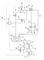
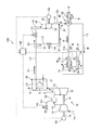
- FIG. 1 is a diagram illustrating an example of a GTCC power plant according to the first embodiment.
- FIG. 2 is a block diagram illustrating an example of the configuration of the control unit according to the first embodiment.
- FIG. 3 is a timing chart showing the operation of the GTCC power plant according to the first embodiment.
- FIG. 4 is a flowchart showing the operation of the GTCC power plant according to the first embodiment.
- FIG. 5 is a diagram illustrating an example of a GTCC power plant that performs a closed bypass operation.
- FIG. 6 is a diagram illustrating an example of a GTCC power plant that performs a load reduction follow-up operation.
- FIG. 7 is a graph schematically showing the relationship between the time after the load reduction request is input and the GTCC load.
- FIG. 8 is a timing chart showing the operation of the GTCC power plant according to the second embodiment.
- FIG. 9 is a flowchart showing the operation of the GTCC power plant according to the second embodiment.
- FIG. 10 is a graph simply showing the relationship between the time after the load reduction request is input and the GTCC load.
- FIG. 11 is a flowchart showing the operation of the GTCC power plant according to the modification.
- FIG. 1 is a diagram illustrating an example of a GTCC power plant 100 according to the first embodiment.
- the GTCC power plant 100 includes a gas turbine 10, an exhaust heat recovery boiler 20, a steam turbine 30, a condenser 40, a cooling water supply unit 50, and a control unit 60. Yes.
- the gas turbine 10 includes a compressor 11, a combustor 12, and a turbine 13.
- the compressor 11 takes in air from the air introduction line La and compresses it into high-temperature and high-pressure compressed air.
- the combustor 12 supplies fuel to the compressed air supplied from the compressor 11 via the compressed air supply line Lb and burns it.
- the fuel supply line Ld is connected to the combustor 12.
- the fuel supply line Ld supplies fuel to the combustor 12.
- the fuel adjustment valve Vd is provided in the fuel supply line Ld.
- the fuel adjustment valve Vd adjusts the fuel supply amount to the combustor 12 by adjusting the opening degree.
- the opening degree of the fuel adjustment valve Vd is adjusted by the control unit 60.
- the turbine 13 is rotated by high-temperature and high-pressure combustion gas supplied from the combustor 12 via the combustion gas supply line Lc.
- the turbine 13 is connected to the rotor 14 and the drive shaft 15.
- the rotor 14 and the drive shaft 15 are rotated by the rotation of the turbine 13.
- the drive shaft 15 is connected to the generator G1.
- the generator G1 converts the rotational energy of the drive shaft 15 into electric energy and outputs it.
- the generator G1 transmits the output value (load) to the control unit 60. Further, the turbine 13 discharges the combustion gas (exhaust gas) used for the rotation to the exhaust gas line Le.
- the exhaust heat recovery boiler 20 is installed in the exhaust gas line Le, performs heat exchange with the exhaust gas flowing through the exhaust gas line Le, recovers the heat of the exhaust gas, and generates steam.
- the exhaust heat recovery boiler 20 discharges the generated steam to the main steam line L1.
- the exhaust heat recovery boiler 20 has an exhaust heat recovery unit 21.
- the exhaust heat recovery unit 21 is a heat exchanger, and a heat medium (steam) flows inside the heat transfer tube L0, and performs heat exchange between the exhaust gas flowing outside the heat transfer tube and the heat medium flowing inside.
- the exhaust heat recovery unit 21 in FIG. 1 shows one heat exchanger, but may include a plurality of heat exchangers such as a economizer, a heater, and a reheater.
- the heat transfer pipe L0 connects the condensate line L3 and the main steam line L1.
- the steam turbine 30 is connected to the main steam line L1.
- the steam turbine 30 includes a turbine 31 and a rotor 32.
- the turbine 31 is rotated by steam supplied from the exhaust heat recovery boiler 20 via the main steam line L1.
- the rotor 32 is rotated by the rotation of the turbine 31.
- the rotor 32 is connected to the generator G2.
- the generator G2 converts the rotational energy of the rotor 32 into electric energy and outputs it.
- the generator G2 transmits the output value (load) to the control unit 60.
- the turbine 31 discharges the steam used for the rotation to the discharge line L2.
- the main steam line L1 is provided with a main steam valve V1.
- the main steam valve V1 adjusts the flow rate of the steam flowing through the main steam line L1.
- the opening / closing operation of the main steam valve V1 is controlled by the control unit 60.
- a bypass line L4 is provided in the main steam line L1.
- the bypass line L4 branches from the main steam line L1 and is connected to the discharge line L2 on the downstream side of the steam turbine 30 in the steam flow direction.
- the bypass line L4 supplies at least a part of the steam flowing through the main steam line L1 to the exhaust line L2, bypassing the steam turbine 30.
- a bypass valve V4 is provided in the bypass line L4.
- the bypass valve V4 adjusts the flow rate of the steam flowing through the bypass line L4.
- the opening / closing operation of the bypass valve V4 is controlled by the control unit 60.
- the condenser 40 is disposed downstream of the steam turbine 30 in the steam flow direction, and is connected to, for example, the discharge line L2.
- the condenser 40 condenses the moisture in the steam supplied from the discharge line L2 to generate condensate.
- the condenser 40 discharges the generated condensate to the condensate line L3.
- the condensate line L3 is connected to the heat transfer tube L0. Therefore, the condensate supplied from the condensate line L3 flows through the heat transfer pipe L0.
- the cooling water supply unit 50 supplies cooling water to the condenser 40.
- the cooling water supply unit 50 includes a water intake pipe 51 and a drain pipe 52. One end of the intake pipe 51 is disposed in the sea, and the other end is connected to the condenser 40.
- the intake pipe 51 is provided with a first pump 53.
- the first pump 53 pumps seawater, distributes the intake pipe 51 and supplies it to the condenser 40.
- the drain pipe 52 has one end connected to the condenser 40 and the other end disposed in the sea. The drain pipe 52 circulates the cooling water supplied to the condenser 40 and used for cooling and returns it to the sea.
- the cooling water supply unit 50 has a branch pipe 54.
- the branch pipe 54 is branched from the first portion 51 a of the intake pipe 51 upstream of the first pump 53 in the flow direction of the cooling water. Further, the branch pipe 54 is connected to the second portion 51 b of the intake pipe 51 on the downstream side of the first pump 53 in the coolant flow direction. Therefore, the branch pipe 54 is connected to the intake pipe 51 so as to bypass the first pump 53.
- the branch pipe 54 is provided with a second pump 55.
- the second pump 55 pumps up seawater, circulates the second portion 51 b and the intake pipe 51 from the intake pipe 51 via the first portion 51 a and the branch pipe 54, and supplies them to the condenser 40.
- the control unit 60 controls the operation of each unit of the GTCC power plant 100.
- FIG. 2 is a block diagram illustrating an example of the configuration of the control unit 60. As shown in FIG. 2, the control unit 60 includes a main steam valve control unit 61, a bypass valve control unit 62, a fuel adjustment valve control unit 63, and a pump control unit 64.
- the main steam valve control unit 61 controls the opening / closing operation of the main steam valve V1.
- the bypass valve control unit 62 controls the opening / closing operation of the bypass valve V4.
- the bypass valve control unit 62 can adjust the opening degree of the bypass valve V4.
- the fuel adjustment valve control unit 63 controls the opening / closing operation of the fuel adjustment valve Vd.
- the fuel adjustment valve control unit 63 can adjust the opening of the fuel adjustment valve Vd.
- the pump control unit 64 controls the operations of the first pump 53 and the second pump 55.
- the pump control unit 64 can separately control the operation of the first pump 53 and the operation of the second pump 55.
- FIG. 3 is a timing chart showing the operation of the GTCC power plant 100.
- the horizontal axis in FIG. 3 indicates time.
- FIG. 4 is a flowchart showing the operation of the GTCC power plant 100.
- FIG. 4 illustrates the operation of each unit shown in FIG. 3 in order.
- the operation of the GTCC power plant 100 will be described with reference to FIGS. 3 and 4.
- control unit 60 starts the gas turbine 10.
- the compressor 11 compresses air
- the compressed air and fuel are combusted in the combustor 12, and the turbine 13 is rotated by the combustion gas.
- the generator G ⁇ b> 1 starts power generation by the rotation of the turbine 13 and transmits an output value to the control unit 60.
- the controller 60 adjusts the opening of the fuel adjustment valve Vd according to the target value (step S10).
- the control unit 60 sets the target value of the total load (hereinafter referred to as “GTCC load”) of the gas turbine 10 and the steam turbine 30 to 100%. Set. Then, the control unit 60 adjusts the opening degree of the fuel adjustment valve Vd so that the GTCC load becomes 100%.
- GTCC load target value of the total load
- the relationship between the target value and the opening of the fuel adjustment valve Vd can be obtained in advance and stored in the control unit 60 as a data table.
- the main steam valve control unit 61 sets the main steam valve V1 to an open state (step S20), and the bypass valve control unit 62 sets the bypass valve V4 to a closed state (step S30).
- step S20 and step S30 the main steam line L1 is opened and the bypass line L4 is closed.
- the pump control unit 64 starts the first pump 53 and supplies cooling water to the condenser 40 (step S40).
- step S10 to step S40 the control unit 60 opens the main steam valve V1, sets the opening of the fuel adjustment valve Vd to an opening corresponding to the target value of the GTCC load, and sets the bypass valve V4. Closed bypass operation is performed to make it closed.
- the controller 60 may perform all operations from step S20 to step S40 at the same time, or may perform at least one operation at different times.
- FIG. 5 is a diagram illustrating an example of the GTCC power plant 100 that performs the closed bypass operation. As shown in FIG. 5, in the closed bypass operation, the bypass valve V4 is closed and the bypass line L4 is closed. For this reason, the steam S1 generated in the exhaust heat recovery boiler 20 is supplied to the steam turbine 30 via the main steam line L1 without flowing through the bypass line L4.
- the turbine 31 is rotated by the steam S1 supplied from the exhaust heat recovery boiler 20.
- the generator G ⁇ b> 2 starts power generation by the rotation of the turbine 31 and transmits an output value to the control unit 60.
- the steam turbine 30 discharges the steam S2 used for rotation and supplies it to the condenser 40 via the discharge line L2.
- the condenser 40 condenses the water in the supplied steam S2 to generate the condensate W, and supplies it to the exhaust heat recovery boiler 20 via the condensate line L3.
- the cooling water supply unit 50 cools the condenser 40 by supplying the cooling water R to the condenser 40 by the first pump 53.
- the cooling water R that has cooled the condenser 40 is discharged from the drain pipe 52 into the sea.
- the control unit 60 detects whether or not a load reduction request for lowering the target value of the GTCC load from 100% has been input (step S50).
- the load reduction request is input when the GTCC load of the GTCC power plant 100 is reduced, for example, when a demand drop occurs in the power system.
- the control unit 60 When an input of a load reduction request is detected (Yes in step S50, time t2), the control unit 60 performs a load reduction follow-up operation so that the GTCC load follows the new target value in the load reduction request.
- the load reduction follow-up operation will be specifically described by taking as an example a case where a load reduction request for reducing the target value of the GTCC load to 80% is input.
- the pump control unit 64 activates the second pump 55 (step S60).
- the second pump 55 When the second pump 55 is activated, the pumped seawater flows from the intake pipe 51 through the first portion 51 a and the branch pipe 54, flows through the second portion 51 b and the intake pipe 51, and is supplied to the condenser 40. . Therefore, the condenser 40 is cooled by the cooling water R supplied by the first pump 53 and the cooling water R supplied by the second pump 55. For this reason, the amount of the cooling water R per unit time for cooling the condenser 40 is larger than when only the first pump 53 is activated.
- the bypass valve V4 When the bypass valve V4 is in the open state, the steam S1 that does not pass through the steam turbine 30 is supplied to the condenser 40.
- the steam S1 has a larger amount of thermal energy than the steam S2 passing through the steam turbine 30. Since the cooling water R is supplied to the condenser 40 by the first pump 53 and the second pump 55, the temperature of the cooling water R in the condenser 40 is prevented from rising more than necessary, and the condenser 40 The rise of the outlet temperature of the is suppressed.
- the fuel adjustment valve control unit 63 decreases the opening of the fuel adjustment valve Vd in accordance with the new target value in the load reduction request (step S70). That is, the fuel adjustment valve control unit 63 decreases the opening of the fuel adjustment valve Vd in order to reduce the amount of fuel supplied to the combustor 12. At this time, the fuel adjustment valve control unit 63 controls the opening of the fuel adjustment valve Vd so that the opening gradually decreases with time.
- FIG. 6 is a diagram illustrating an example of the GTCC power plant 100 that performs the load reduction follow-up operation. As shown in FIG. 6, by opening the bypass valve V4, the bypass line L4 is opened, and the main steam line L1 and the discharge line L2 are connected. For this reason, a part of the steam S1 flowing through the main steam line L1 is sent to the discharge line L2 via the bypass line L4 and supplied to the condenser 40.
- step S70 the bypass valve control unit 62 gradually increases the opening degree of the bypass valve V4 as time elapses. For example, as shown in FIG. 3, the bypass valve control unit 62 increases the opening of the bypass valve V4 at a constant rate. Further, the bypass valve control unit 62 adjusts the speed of opening increase so that, for example, the opening of the bypass valve V4 is fully opened before the GTCC load reaches the target value (time t3). When the opening degree of the bypass valve V4 is fully opened, the bypass valve control unit 62 thereafter maintains the opening degree of the bypass valve V4 in the fully opened state.
- control unit 60 detects whether or not the GTCC load has reached the target value (step S80), and continues the operation until the GTCC load reaches the target value (No in step S80).
- the bypass valve control unit 62 changes the bypass valve V4 to the closed state (step S90).
- the bypass valve control unit 62 gradually decreases the opening degree of the bypass valve V4 as time elapses. For example, as shown in FIG. 3, the bypass valve control unit 62 decreases the opening degree of the bypass valve V4 at a constant rate. When the opening degree of the bypass valve V4 is fully closed (time t5), the bypass valve control unit 62 thereafter maintains the opening degree of the bypass valve V4 in the fully closed state.
- the fuel adjustment valve control unit 63 decreases the opening of the fuel adjustment valve Vd (step S90).
- the operation of reducing the opening of the fuel adjustment valve Vd by the fuel adjustment valve control unit 63 is performed in parallel with the operation of changing the bypass valve V4 to the closed state by the bypass valve control unit 62 described above.
- the present invention is not limited to this. For example, either one may be performed first.
- the opening degree of the fuel adjustment valve Vd decreases, the load on the gas turbine 10 decreases.
- the control unit 60 suppresses the variation of the GTCC load by decreasing the load of the gas turbine 10 with respect to the load increase of the steam turbine 30.
- FIG. 3 shows an example in which the opening of the fuel adjustment valve Vd is controlled to become a constant value at time t5.
- the load of the steam turbine 30 that increases when the bypass valve V4 is closed is estimated in advance, and the opening of the fuel adjustment valve Vd corresponding to the approximate value is calculated. And what is necessary is just to reduce gradually until the opening degree of the fuel adjustment valve Vd becomes a calculated value.
- the fuel adjustment valve control unit 63 may adjust the opening of the fuel adjustment valve Vd according to the GTCC load while detecting the loads of the gas turbine 10 and the steam turbine 30. In this case, the opening degree of the fuel adjustment valve Vd may be adjusted continuously after time t5.
- the pump control unit 64 stops the operation of the second pump 55 (step S100, time t5). After stopping the operation of the second pump 55, or when no load reduction request input is detected in step S50 (No in step S50), it is detected whether an operation end instruction for the GTCC plant 100 is input. (Step S110) If it is detected, the operation is terminated (Yes in Step S110). If no operation end instruction is detected (No in step S110), the operations after step S50 are repeated. In this way, the control unit 60 performs the load reduction follow-up operation.
- the GTCC power plant 100 when a load reduction request is input, bypasses a part of the steam S1 flowing from the exhaust heat recovery boiler 20 to the main steam line L1 in the load reduction follow-up operation. Flow to line L4. For this reason, the supply amount of the steam S1 supplied to the steam turbine 30 is reduced. Thereby, since the load of the steam turbine 30 can be efficiently reduced in response to the load reduction request, the load followability of the steam turbine 30 can be improved.
- FIG. 7 is a graph simply showing the relationship between the time after the load reduction request is input and the GTCC load.
- the horizontal axis represents time
- the vertical axis represents the value of the GTCC load.
- a solid curve 102 in FIG. 7 shows a relationship when the load reduction follow-up operation of the present embodiment is performed.
- a dashed-dotted line curve 104 in FIG. 7 shows a relationship when the opening degree of the fuel adjustment valve Vd is lowered while the bypass line L4 is closed without performing the load reduction follow-up operation. Times t2 and t4 on the horizontal axis in FIG. 7 correspond to times t2 and t4 in FIG.
- the GTCC power plant 100 performs load reduction tracking, whereby the time until the GTCC load reaches the target value is reduced by, for example, ⁇ ta. For this reason, the GTCC power plant 100 can improve the followability of the GCTT load.
- This time ⁇ ta varies depending on an increasing speed when increasing the opening degree of the bypass valve V4, a changing speed when changing the opening degree of the fuel adjustment valve Vd, and the like.
- the fuel adjustment valve control unit 63 when adjusting the opening of the fuel adjustment valve Vd, gradually decreases the opening as time passes. Further, when switching the open / close state of the bypass valve V4, the bypass valve control unit 62 gradually changes the opening as time passes. Thereby, since it can suppress that the load of the gas turbine 10 and the steam turbine 30 fluctuates rapidly, the fall of power supply quality can be suppressed.
- 2nd Embodiment demonstrates the operation
- the load increase request is input when the GTCC load is increased, for example, when an increase in demand is expected in the power system.
- FIG. 8 is a timing chart showing the operation of the GTCC power plant 100.
- the horizontal axis in FIG. 8 indicates time.
- FIG. 9 is a flowchart showing the operation of the GTCC power plant 100.
- FIG. 9 illustrates the operation of each unit shown in FIG. 8 in order.
- the operation of the GTCC power plant 100 will be described with reference to FIGS. 8 and 9.
- a case where the time (for example, time t8 in FIG. 8) at which the load increase request is scheduled will be described as an example.
- the control unit 60 performs the closed bypass operation in which the main steam valve V1 is opened, the opening of the fuel adjustment valve Vd is set to an opening corresponding to the target value of the GTCC load, and the bypass valve V4 is closed. .
- the control part 60 shall set the opening degree of the fuel adjustment valve Vd so that the GTCC power plant 100 may become 80% of GTCC load, for example.
- the target value of GTCC load in closed bypass operation should just be less than 100%.
- the control unit 60 causes the GTCC load to follow the new target value in the load increase request. I do.
- the predetermined time time from time t6 to time t8 can be set in advance.
- the load increase follow-up operation will be specifically described by taking as an example a case where a load increase request for increasing the target value of the GTCC load to 100% is input.
- the bypass valve control unit 62 changes the bypass valve V4 to the open state (step S210). By opening the bypass valve V4, the bypass line L4 is opened, and the main steam line L1 and the discharge line L2 are connected. For this reason, a part of the steam S1 flowing through the main steam line L1 is sent to the discharge line L2 via the bypass line L4 and supplied to the condenser 40.
- step S210 the bypass valve control unit 62 gradually increases the opening degree of the bypass valve V4 as time elapses. For example, as shown in FIG. 8, the bypass valve control unit 62 increases the opening degree of the bypass valve V4 at a constant rate. Further, the bypass valve control unit 62 adjusts the speed of opening increase so that the opening of the bypass valve V4 is fully opened at the time (time t7) before the load increase request is input, for example. When the opening degree of the bypass valve V4 is fully opened, the bypass valve control unit 62 thereafter maintains the opening degree of the bypass valve V4 in the fully opened state.
- step S220 the fuel adjustment valve control unit 63 adjusts so that the opening of the fuel adjustment valve Vd increases (step S220).
- step S220 since the opening degree of the fuel adjustment valve Vd increases, the load on the gas turbine 10 increases.
- the control part 60 suppresses the fluctuation
- FIG. 8 shows an example in which the opening of the fuel adjustment valve Vd is controlled to increase at a constant rate, but the present invention is not limited to this.
- the fuel adjustment valve control unit 63 may adjust the opening of the fuel adjustment valve Vd according to the GTCC load while detecting the loads of the gas turbine 10 and the steam turbine 30. In this case, the opening degree of the fuel adjustment valve Vd may be increased or decreased according to the GTCC load.
- the pump control unit 64 activates the second pump 55 (step S230).
- the second pump 55 When the second pump 55 is activated, the pumped seawater flows from the intake pipe 51 through the first portion 51 a and the branch pipe 54, flows through the second portion 51 b and the intake pipe 51, and is supplied to the condenser 40. . Since the cooling water R is supplied to the condenser 40 by the first pump 53 and the second pump 55, the temperature of the cooling water R in the condenser 40 is prevented from rising more than necessary, and the condenser 40 The rise of the outlet temperature of the is suppressed.
- the control unit 60 detects whether or not a load increase request is input (step S240), and waits until a load increase request is input (No in step S240).
- the fuel adjustment valve control unit 63 increases the opening of the fuel adjustment valve Vd according to the new target value in the load increase request (step S250).
- the fuel adjustment valve control unit 63 controls the opening of the fuel adjustment valve Vd so that the opening gradually increases with time.
- the bypass valve control unit 62 maintains the bypass valve V4 in the open state even after the load increase request input time t8 has elapsed, and changes the bypass valve V4 to the closed state at time t9 after the predetermined time has elapsed (step S9). S250).
- the time for maintaining the bypass valve V4 in the open state after the input of the load increase request that is, the time from the time t8 to the time t9, may be set in advance, for example, controlled according to the value of the GTCC load.
- the unit 60 may calculate.
- the operation of changing the bypass valve V4 to the closed state by the bypass valve control unit 62 is performed in parallel with the operation of increasing the opening of the fuel adjustment valve Vd by the fuel adjustment valve control unit 63.
- the present invention is not limited to this.
- either one may be performed first.
- the bypass valve control unit 62 gradually decreases the opening degree of the bypass valve V4 with time.
- the bypass valve control unit 62 decreases the opening degree of the bypass valve V4 at a constant rate.
- the bypass valve control unit 62 thereafter maintains the opening degree of the bypass valve V4 in the fully closed state.
- the flow of the steam S1 in the bypass line L4 is blocked by closing the bypass valve V4, and the steam S1 from the exhaust heat recovery boiler 20 flows to the main steam line L1. For this reason, the supply amount of the steam S1 supplied to the steam turbine 30 increases.
- the time when the bypass valve V4 is fully closed, the time when the opening of the fuel adjustment valve Vd is constant, and the time when the GTCC load reaches the target value (100%) are at time t10.
- the case where it corresponds is given as an example, it is not limited to this. Any time may be before or after time t10.
- the pump control unit 64 stops the operation of the second pump 55 when the bypass valve V4 is fully closed (step S260, time t10). In this way, the control unit 60 performs the load increase following operation.
- a part of the steam S1 flowing from the exhaust heat recovery boiler 20 to the main steam line L1 is caused to flow in advance to the bypass line L4, and a load increase request is input.
- the supply amount of the steam S1 that is supplied to the steam turbine 30 can be increased efficiently.
- the load on the steam turbine 30 can be increased earlier than the amount of steam generated in the exhaust heat recovery boiler 20 increases with an increase in the load on the gas turbine 10. Thereby, the load followability of the steam turbine 30 can be improved.
- FIG. 10 is a graph simply showing the relationship between the time after the load increase request is input and the GTCC load.
- the horizontal axis represents time
- the vertical axis represents the value of GTCC load.
- a solid curve 106 in FIG. 10 shows a relationship when the load increase follow-up operation of the present embodiment is performed.
- a dashed-dotted curve 108 in FIG. 7 shows a relationship when the opening degree of the fuel adjustment valve Vd is increased while the bypass line L4 is closed without performing the load increase follow-up operation. Times t8 and t10 on the horizontal axis in FIG. 10 correspond to times t8 and t10 in FIG.
- the GTCC power plant 100 performs load increase tracking, whereby the time until the GTCC load reaches the target value is reduced by, for example, ⁇ tb. For this reason, the GTCC power plant 100 can improve the followability of the GCTT load.
- This time ⁇ tb varies according to a decrease speed when the opening degree of the bypass valve V4 is decreased, a change speed when the opening degree of the fuel adjustment valve Vd is changed, and the like.
- FIG. 11 is a flowchart showing an operation flow of the GTCC power plant 100 according to the modification.
- the control unit 60 opens the main steam valve V1, sets the opening of the fuel adjustment valve Vd to an opening corresponding to the target value of the GTCC load, and closes the bypass valve V4.
- the closed bypass operation is performed (step S310).
- the GTCC power plant 100 performs the operations from step S10 to step S40 in the first embodiment, for example, as the closed bypass operation.
- step S320 the control unit 60 detects whether or not a load reduction request for lowering the target value of the GTCC load has been input (step S320).
- step S320 the control unit 60 performs a load reduction follow-up operation to cause the GTCC load to follow the new target value in the load reduction request (step S330).
- step S330 the GTCC power plant 100 performs the operations from step S60 to step S100 in the first embodiment, for example, as the load reduction follow-up operation.
- Step S340 the control unit 60 detects whether or not there is a plan to input the load increase request to increase the target value of the GTCC load.
- the control unit 60 causes the GTCC load to follow the new target value when the load increase request is input. Is performed (step S350).
- step S350 the GTCC power plant 100 performs the operations from step S210 to step S260 in the second embodiment, for example, as the load increase following operation.
- step S340 After performing the load reduction follow-up operation, after performing the load increase follow-up operation, or when the input schedule of the load increase request is not detected (No in step S340), the control unit 60 ends the operation of the GTCC power plant 100. It is determined whether or not to perform (step S360). When it is determined that the operation is to be ended (Yes in step S360), the GTCC power plant 100 ends the operation of the GTCC power plant 100 according to the determination. When it is determined that the operation is to be continued (No in Step S360), the GTCC power plant 100 repeatedly performs the operations after Step S320.
- the GTCC power plant 100 can efficiently increase or decrease the load of the steam turbine 30 regardless of whether a load reduction request or a load increase request is input. Thereby, it becomes possible to improve the load followability of a steam turbine.
- the configuration in which one steam turbine 30 is provided has been described as an example.
- the configuration is not limited thereto, and the configuration in which the steam turbine 30 is provided in a plurality of stages may be used.
- the downstream end of the bypass line L4 may be connected between the high-pressure side steam turbine and the low-pressure side steam turbine.
- control unit 60 changes the opening degree of the bypass valve V4 and the fuel adjustment valve Vd at a constant rate in the load reduction follow-up operation and the load increase follow-up operation has been described as an example.
- the present invention is not limited to this.
- the control unit 60 may change the opening degree of the bypass valve V4 and the fuel adjustment valve Vd stepwise. Further, the control unit 60 may gradually increase or decrease the rate of change in the opening degree of the bypass valve V4 and the fuel adjustment valve Vd.
- the load of the steam turbine 30 increases by closing the bypass valve V4 in load reduction follow-up operation
- the case of decreasing the load of the gas turbine 10 to suppress the fluctuation of the GTCC load is taken as an example.
- the present invention is not limited to this. For example, if the variation of the GTCC load is within an allowable range, the load on the gas turbine 10 may not be reduced.
- the cooling water pumped up by the first pump 53 and the second pump 55 in the cooling water supply unit 50 is merged at the second portion 51 b of the intake pipe 51 and supplied to the condenser 40.
- the present invention is not limited to this.
- the cooling water pumped up by the first pump 53 and the cooling water pumped up by the second pump 55 may be supplied to the condenser 40 through different paths.
Landscapes
- Engineering & Computer Science (AREA)
- Chemical & Material Sciences (AREA)
- Combustion & Propulsion (AREA)
- Mechanical Engineering (AREA)
- General Engineering & Computer Science (AREA)
- Physics & Mathematics (AREA)
- Fluid Mechanics (AREA)
- Engine Equipment That Uses Special Cycles (AREA)
- Control Of Turbines (AREA)
Abstract
GTCC発電プラント(100)は、閉バイパス運転においてGTCC負荷の目標値を下げる負荷下げ要求が入力された場合に、主蒸気弁(V1)を開いた状態で、燃料調整弁(Vd)の開度を目標値に応じて減少させ、バイパス弁(V4)を開いた状態とした後、GTCC負荷が目標値に到達した場合にバイパス弁(V4)を閉じた状態とする負荷下げ追従運転を燃料調整弁(Vd)、主蒸気弁(V1)及びバイパス弁(V4)に対して行わせる制御部を備える。
Description
本発明は、コンバインドサイクルプラント及びコンバインドサイクルプラントの運転制御方法に関する。
ガスタービンコンバインドサイクル(Gas Turbine Combined Cycle:GTCC)発電プラントは、ガスタービンと、ガスタービンから排出される排ガスの熱を回収し蒸気を生成する排熱回収ボイラと、排熱回収ボイラで生成された蒸気により回転する蒸気タービンとを備えている(例えば、特許文献1参照)。GTCC発電プラントでは、ガスタービン及び蒸気タービンの回転により、例えば発電機が駆動され、回転エネルギーが電気エネルギーに変換される。
GTCC発電プラントにおいて、プラント全体の負荷を変動させる場合には、ガスタービンの負荷を変動させ、蒸気タービンの負荷を追従して変動させる。つまり、ガスタービンの負荷が変動すると、排ガスの流量及び温度が変動するため、排ガスの排熱量が変動する。排熱量が変動すると、排熱回収ボイラで発生する蒸気の量が変動する。蒸気発生量が変動すると、蒸気タービンに流入する蒸気量が変動するため、蒸気タービンの負荷が変動する。これにより、プラント全体の負荷が変動する。このため、GTCC発電プラントは、全体の負荷変動に対するガスタービンの負荷追従性に対して、蒸気タービンの負荷追従性が低くなる。
本発明は、上記に鑑みてなされたものであり、全体の負荷変動に対する蒸気タービンの追従性を向上させることが可能なコンバインドサイクルプラント及びコンバインドサイクルプラントの運転制御方法を提供することを目的とする。
本発明に係るコンバインドサイクルプラントは、空気を圧縮する圧縮機と、燃料供給ラインから燃料が供給され前記圧縮機で圧縮された圧縮空気を燃焼させる燃焼器と、前記燃焼器で生じた燃焼ガスにより回転するタービンと、を有し、燃料供給量を調整する燃料調整弁が前記燃料供給ラインに設けられたガスタービンと、前記ガスタービンから排出される排ガスの熱を回収し蒸気を生成する排熱回収ボイラと、前記排熱回収ボイラで生成された前記蒸気により回転する蒸気タービンと、前記排熱回収ボイラで生成された前記蒸気を前記蒸気タービンに供給する主蒸気ラインと、前記主蒸気ラインに設けられ、前記蒸気の流通量を調整する主蒸気弁と、前記主蒸気ラインから分岐し、前記蒸気タービンよりも前記蒸気の流れ方向下流側に接続されたバイパスラインと、前記バイパスラインに設けられ、前記蒸気の流通量を調整するバイパス弁と、前記主蒸気弁を開いた状態とし、前記燃料調整弁の開度を前記ガスタービン及び前記蒸気タービンの合計負荷の目標値に応じた開度とし、前記バイパス弁を閉じた状態とする閉バイパス運転と、前記閉バイパス運転において、前記合計負荷の前記目標値を下げる負荷下げ要求が入力された場合に、前記主蒸気弁を開いた状態で、前記燃料調整弁の開度を前記目標値に応じて減少させ、前記バイパス弁を開いた状態とした後、前記合計負荷が前記目標値に到達した場合に前記バイパス弁を閉じた状態とする負荷下げ追従運転と、を前記燃料調整弁、前記主蒸気弁及び前記バイパス弁に対して行わせる制御部と、を備える。
従って、負荷下げ要求が入力された場合には、排熱回収ボイラから主蒸気ラインに流れる蒸気の一部がバイパスラインに流れるため、蒸気タービンに供給される蒸気の供給量が低減する。この場合、ガスタービンの負荷低下に伴って排熱回収ボイラで蒸気発生量が低減するよりも早く、蒸気タービンの負荷を低減させることができる。これにより、全体の負荷変動に対する蒸気タービンの追従性を向上させることが可能となる。
本発明のコンバインドサイクルプラントにおいて、前記制御部は、前記負荷下げ追従運転において、前記バイパス弁の開度を徐々に変化させる。
従って、バイパス弁の開度を徐々に変化させることで、蒸気タービンの負荷が不安定になることを防止できる。
本発明のコンバインドサイクルプラントにおいて、前記制御部は、前記負荷下げ追従運転において、前記バイパス弁を閉じた状態とすることで前記蒸気タービンの負荷が増加する場合には、前記蒸気タービンの負荷の増加に応じて前記ガスタービンの負荷が減少するように、前記燃料調整弁の開度を減少させる。
従って、ガスタービン及び蒸気タービンの合計負荷が変動することを抑制できる。
本発明のコンバインドサイクルプラントは、前記蒸気タービンよりも前記蒸気の流れ方向下流側に配置される復水器をさらに備え、前記蒸気タービン及び前記バイパスラインは、前記復水器に接続される。
従って、排熱回収ボイラからバイパスラインに流れる蒸気が復水器によって凝縮されるため、復水として再利用することができる。
本発明のコンバインドサイクルプラントは、前記復水器を冷却する冷却水を前記復水器に供給する冷却水供給部をさらに備え、前記制御部は、前記閉バイパス運転において前記復水器に供給する冷却水の単位時間当たりの量よりも、前記負荷下げ追従運転において前記復水器に供給する冷却水の単位時間当たりの量の方が多くなるようにするポンプ制御部を有する。
従って、バイパスラインから供給される蒸気により復水器での冷却水の温度が必要以上に上昇することを抑制できるため、復水器の出口温度の上昇を抑制できる。
本発明のコンバインドサイクルプラントにおいて、前記冷却水供給部は、前記閉バイパス運転及び前記負荷下げ追従運転において前記復水器に冷却水を供給する第1供給部と、前記負荷下げ追従運転において前記第1供給部と共に前記復水器に冷却水を供給する第2供給部と、を有する。
従って、復水器に供給する冷却水の単位時間当たりの量を多くする場合に第2供給部を用いることで、冷却水の供給量を容易に調整することができる。
本発明のコンバインドサイクルプラントにおいて、前記制御部は、前記閉バイパス運転において、前記合計負荷の前記目標値を上げる負荷上げ要求が入力される場合には、前記主蒸気弁を開いた状態で、前記バイパス弁を開いた状態として前記負荷上げ要求の入力を待機し、前記負荷上げ要求の入力後に前記燃料調整弁の開度を前記目標値に応じて増加させ、前記バイパス弁を閉じた状態とする負荷上げ追従運転を、前記燃料調整弁、前記主蒸気弁及び前記バイパス弁に対して行わせる。
従って、負荷上げ要求が入力される場合には、排熱回収ボイラから主蒸気ラインに流れる蒸気の一部を予めバイパスラインに流しておき、負荷上げ要求が入力された場合に、バイパスラインに流しておいた蒸気を主蒸気ラインに流すため、蒸気タービンに供給される蒸気の供給量を効率的に増加させることができる。この場合、ガスタービンの負荷増加に伴って排熱回収ボイラで蒸気発生量が増加するよりも早く、蒸気タービンの負荷を増加させることができる。これにより、全体の負荷変動に対する蒸気タービンの追従性を向上させることが可能となる。
また、本発明に係るコンバインドサイクルプラントは、空気を圧縮する圧縮機と、燃料供給ラインから燃料が供給され前記圧縮機で圧縮された圧縮空気を燃焼させる燃焼器と、前記燃焼器で生じた燃焼ガスにより回転するタービンと、を有し、燃料供給量を調整する燃料調整弁が前記燃料供給ラインに設けられたガスタービンと、前記ガスタービンから排出される排ガスの熱を回収し蒸気を生成する排熱回収ボイラと、前記排熱回収ボイラで生成された前記蒸気により回転する蒸気タービンと、前記排熱回収ボイラで生成された前記蒸気を前記蒸気タービンに供給する主蒸気ラインと、前記主蒸気ラインに設けられ、前記蒸気の流通量を調整する主蒸気弁と、前記主蒸気ラインから分岐し、前記蒸気タービンよりも前記蒸気の流れ方向下流側に接続されたバイパスラインと、前記バイパスラインに設けられ、前記蒸気の流通量を調整するバイパス弁と、前記主蒸気弁を開いた状態とし、前記燃料調整弁の開度を前記ガスタービン及び前記蒸気タービンの合計負荷の目標値に応じた開度とし、前記バイパス弁を閉じた状態とする閉バイパス運転と、前記閉バイパス運転において、前記合計負荷の前記目標値を上げる負荷上げ要求が入力される場合には、前記主蒸気弁を開いた状態で、前記バイパス弁を開いた状態として前記負荷上げ要求の入力を待機し、前記負荷上げ要求の入力後に前記燃料調整弁の開度を前記目標値に応じて増加させ、前記バイパス弁を閉じた状態とする負荷上げ追従運転と、を前記燃料調整弁、前記主蒸気弁及び前記バイパス弁に対して行わせる制御部と、を備える。
従って、排熱回収ボイラから主蒸気ラインに流れる蒸気の一部を予めバイパスラインに流しておき、負荷上げ要求が入力された場合に、バイパスラインに流しておいた蒸気を主蒸気ラインに流すため、蒸気タービンに供給される蒸気の供給量を効率的に増加させることができる。この場合、ガスタービンの負荷増加に伴って排熱回収ボイラで蒸気発生量が増加するよりも早く、蒸気タービンの負荷を増加させることができる。これにより、全体の負荷変動に対する蒸気タービンの追従性を向上させることが可能となる。
本発明のコンバインドサイクルプラントにおいて、前記制御部は、前記負荷上げ追従運転において、前記バイパス弁の開度を徐々に変化させる。
従って、バイパス弁の開度を徐々に変化させることで、蒸気タービンの負荷が不安定になることを防止できる。
本発明のコンバインドサイクルプラントにおいて、前記制御部は、前記負荷上げ追従運転において、前記バイパス弁を開いた状態とすることで前記蒸気タービンの負荷が減少する場合には、前記蒸気タービンの負荷の減少に応じて前記ガスタービンの負荷が増加するように、前記燃料調整弁の開度を増加させる。
従って、ガスタービン及び蒸気タービンの合計負荷が変動することを抑制できる。
本発明のコンバインドサイクルプラントは、前記蒸気タービンよりも前記蒸気の流れ方向下流側に配置される復水器をさらに備え、前記蒸気タービン及び前記バイパスラインは、前記復水器に接続される。
従って、排熱回収ボイラからバイパスラインに流れる蒸気が復水器によって凝縮されるため、復水として再利用することができる。
本発明のコンバインドサイクルプラントは、前記復水器を冷却する冷却水を前記復水器に供給する冷却水供給部をさらに備え、前記制御部は、前記閉バイパス運転において前記復水器に供給する冷却水の単位時間当たりの量よりも、前記負荷上げ追従運転において前記復水器に供給する冷却水の単位時間当たりの量の方が多くなるようにするポンプ制御部を有する。
従って、バイパスラインから供給される蒸気により復水器での冷却水の温度が必要以上に上昇することを抑制できるため、復水器の出口温度の上昇を抑制できる。
本発明のコンバインドサイクルプラントは、前記冷却水供給部は、前記閉バイパス運転及び前記負荷下げ追従運転において前記復水器に冷却水を供給する第1供給部と、前記負荷上げ追従運転において前記第1供給部と共に前記復水器に冷却水を供給する第2供給部と、を有する。
従って、復水器に供給する冷却水の単位時間当たりの量を多くする場合に第2供給部を用いることで、冷却水の供給量を容易に調整することができる。
また、本発明に係るコンバインドサイクルプラントの運転方法は、空気を圧縮する圧縮機と、燃料供給ラインから燃料が供給され前記圧縮機で圧縮された圧縮空気を燃焼させる燃焼器と、前記燃焼器で生じた燃焼ガスにより回転するタービンと、を有し、燃料供給量を調整する燃料調整弁が前記燃料供給ラインに設けられたガスタービンと、前記ガスタービンから排出される排ガスの熱を回収し蒸気を生成する排熱回収ボイラと、前記排熱回収ボイラで生成された前記蒸気により回転する蒸気タービンと、前記排熱回収ボイラで生成された前記蒸気を前記蒸気タービンに供給する主蒸気ラインと、前記主蒸気ラインに設けられ、前記蒸気の流通量を調整する主蒸気弁と、前記主蒸気ラインから分岐し、前記蒸気タービンよりも前記蒸気の流れ方向下流側に接続されたバイパスラインと、前記バイパスラインに設けられ、前記蒸気の流通量を調整するバイパス弁と、を備えるコンバインドサイクルプラントの運転制御方法であって、前記主蒸気弁を開いた状態とし、前記燃料調整弁の開度を前記ガスタービン及び前記蒸気タービンの合計負荷の目標値に応じた開度とし、前記バイパス弁を閉じた状態とする閉バイパス運転を行うことと、前記閉バイパス運転において前記合計負荷の目標値を下げる負荷下げ要求が入力された場合に、前記主蒸気弁を開いた状態で、前記燃料調整弁の開度を前記目標値に応じて減少させ、前記バイパス弁を開いた状態とした後、前記合計負荷が前記目標値に到達した後に前記バイパス弁を閉じた状態とする負荷下げ追従運転を行うことと、を含む。
従って、ガスタービンの負荷低下に伴って排熱回収ボイラで蒸気発生量が低減するよりも早く、蒸気タービンの負荷を低減させることができる。これにより、全体の負荷変動に対する蒸気タービンの追従性を向上させることが可能となる。
また、本発明に係るコンバインドサイクルプラントの運転方法は、空気を圧縮する圧縮機と、燃料供給ラインから燃料が供給され前記圧縮機で圧縮された圧縮空気を燃焼させる燃焼器と、前記燃焼器で生じた燃焼ガスにより回転するタービンと、を有し、燃料供給量を調整する燃料調整弁が前記燃料供給ラインに設けられたガスタービンと、前記ガスタービンから排出される排ガスの熱を回収し蒸気を生成する排熱回収ボイラと、前記排熱回収ボイラで生成された前記蒸気により回転する蒸気タービンと、前記排熱回収ボイラで生成された前記蒸気を前記蒸気タービンに供給する主蒸気ラインと、前記主蒸気ラインに設けられ、前記蒸気の流通量を調整する主蒸気弁と、前記主蒸気ラインから分岐し、前記蒸気タービンよりも前記蒸気の流れ方向下流側に接続されたバイパスラインと、前記バイパスラインに設けられ、前記蒸気の流通量を調整するバイパス弁と、を備えるコンバインドサイクルプラントの運転制御方法であって、前記主蒸気弁を開いた状態とし、前記燃料調整弁の開度を前記ガスタービン及び前記蒸気タービンの合計負荷の目標値に応じた開度とし、前記バイパス弁を閉じた状態とする閉バイパス運転を行うことと、前記閉バイパス運転において、前記合計負荷の前記目標値を上げる負荷上げ要求が入力される場合には、前記主蒸気弁を開いた状態で、前記バイパス弁を開いた状態として前記負荷上げ要求の入力を待機し、前記負荷上げ要求の入力後に前記燃料調整弁の開度を前記目標値に応じて増加させ、前記バイパス弁を閉じた状態とする負荷上げ追従運転を行うことと、を含む。
従って、ガスタービンの負荷増加に伴って排熱回収ボイラで蒸気発生量が増加するよりも早く、蒸気タービンの負荷を増加させることができる。これにより、全体の負荷変動に対する蒸気タービンの追従性を向上させることが可能となる。
本発明によれば、全体の負荷変動に対する蒸気タービンの追従性を向上させることが可能なコンバインドサイクルプラント及びコンバインドサイクルプラントの運転制御方法を提供することができる。
以下、本発明に係るガスタービンコンバインドサイクル(GTCC)発電プラントの実施形態を図面に基づいて説明する。なお、この実施形態によりこの発明が限定されるものではない。また、下記実施形態における構成要素には、当業者が置換可能かつ容易なもの、あるいは実質的に同一のものが含まれる。
<第1実施形態>
図1は、第1実施形態に係るGTCC発電プラント100の一例を示す図である。図1に示すように、GTCC発電プラント100は、ガスタービン10と、排熱回収ボイラ20と、蒸気タービン30と、復水器40と、冷却水供給部50と、制御部60とを備えている。
図1は、第1実施形態に係るGTCC発電プラント100の一例を示す図である。図1に示すように、GTCC発電プラント100は、ガスタービン10と、排熱回収ボイラ20と、蒸気タービン30と、復水器40と、冷却水供給部50と、制御部60とを備えている。
ガスタービン10は、圧縮機11と、燃焼器12と、タービン13とを有している。圧縮機11は、空気導入ラインLaから空気を取り込んで圧縮し、高温高圧の圧縮空気とする。
燃焼器12は、圧縮機11から圧縮空気供給ラインLbを経由して供給される圧縮空気に対して燃料を供給して燃焼させる。燃料供給ラインLdは、燃焼器12に接続されている。燃料供給ラインLdは、燃焼器12に燃料を供給する。燃料調整弁Vdは、燃料供給ラインLdに設けられている。燃料調整弁Vdは、開度を調整することにより、燃焼器12に対する燃料供給量を調整する。燃料調整弁Vdの開度は、制御部60によって調整される。
タービン13は、燃焼器12から燃焼ガス供給ラインLcを経由して供給される高温高圧の燃焼ガスによって回転する。タービン13は、ロータ14及び駆動軸15に連結されている。ロータ14及び駆動軸15は、タービン13の回転によって回転する。駆動軸15は、発電機G1に接続されている。発電機G1は、駆動軸15の回転エネルギーを電気エネルギーに変換して出力する。発電機G1は、出力値(負荷)を制御部60に送信する。また、タービン13は、回転に用いた燃焼ガス(排ガス)を排ガスラインLeに排出する。
排熱回収ボイラ20は、排ガスラインLeに設置され、排ガスラインLeを流れる排ガスと熱交換を行い、排ガスの熱を回収して蒸気を生成する。排熱回収ボイラ20は、生成した蒸気を主蒸気ラインL1に排出する。排熱回収ボイラ20は、排熱回収部21を有している。排熱回収部21は、熱交換器であり、伝熱管L0の内部に熱媒(蒸気)が流れ、伝熱管の外を流れる排ガスと内部を流れる熱媒との間で熱交換を行う。図1の排熱回収部21は1つの熱交換器を示しているが、節炭器(エコノマイザ)、加熱器、再熱器等、複数の熱交換器を備えていてもよい。伝熱管L0は、復水ラインL3と主蒸気ラインL1とを接続している。
蒸気タービン30は、主蒸気ラインL1に接続されている。蒸気タービン30は、タービン31及びロータ32を有している。タービン31は、排熱回収ボイラ20から主蒸気ラインL1を経由して供給される蒸気によって回転する。ロータ32は、タービン31の回転によって回転する。ロータ32は、発電機G2に接続されている。発電機G2は、ロータ32の回転エネルギーを電気エネルギーに変換して出力する。発電機G2は、出力値(負荷)を制御部60に送信する。タービン31は、回転に用いた蒸気を排出ラインL2に排出する。
主蒸気ラインL1には、主蒸気弁V1が設けられている。主蒸気弁V1は、主蒸気ラインL1を流通する蒸気の流量を調整する。主蒸気弁V1の開閉動作は、制御部60によって制御される。
また、主蒸気ラインL1には、バイパスラインL4が設けられている。バイパスラインL4は、主蒸気ラインL1から分岐し、蒸気タービン30よりも蒸気の流れ方向下流側の排出ラインL2に接続されている。バイパスラインL4は、主蒸気ラインL1を流通する蒸気の少なくとも一部を、蒸気タービン30を迂回させて排出ラインL2に供給する。バイパスラインL4には、バイパス弁V4が設けられている。バイパス弁V4は、バイパスラインL4を流通する蒸気の流量を調整する。バイパス弁V4の開閉動作は、制御部60によって制御される。
復水器40は、蒸気タービン30よりも蒸気の流れ方向下流側に配置され、例えば排出ラインL2に接続されている。復水器40は、排出ラインL2から供給される蒸気中の水分を凝縮して、復水を生成する。復水器40は、生成した復水を復水ラインL3に排出する。復水ラインL3は、上記の伝熱管L0に接続されている。したがって、伝熱管L0には、復水ラインL3から供給される復水が流通する。
冷却水供給部50は、復水器40に対して冷却水を供給する。冷却水供給部50は、取水管51と、排水管52とを有している。取水管51は、一端が海中に配置され、他端が復水器40に接続されている。取水管51には、第1ポンプ53が設けられている。第1ポンプ53は、海水を汲み上げ、取水管51を流通させて復水器40に供給する。排水管52は、一端が復水器40に接続され、他端が海中に配置されている。排水管52は、復水器40に供給されて冷却に用いられた冷却水を流通させて海中に戻す。
また、冷却水供給部50は、分岐管54を有している。分岐管54は、取水管51のうち第1ポンプ53よりも冷却水の流れ方向上流側の第1部分51aから分岐して設けられている。また、分岐管54は、取水管51のうち第1ポンプ53よりも冷却水の流れ方向下流側の第2部分51bに接続されている。したがって、分岐管54は、第1ポンプ53を迂回するように、取水管51に接続されている。分岐管54には、第2ポンプ55が設けられている。第2ポンプ55は、海水を汲み上げ、取水管51から第1部分51a及び分岐管54を経由し、第2部分51b及び取水管51を流通させて、復水器40に供給する。
制御部60は、GTCC発電プラント100の各部の動作を制御する。図2は、制御部60の構成の一例を示すブロック図である。図2に示すように、制御部60は、主蒸気弁制御部61と、バイパス弁制御部62と、燃料調整弁制御部63と、ポンプ制御部64とを有している。
主蒸気弁制御部61は、主蒸気弁V1の開閉動作を制御する。バイパス弁制御部62は、バイパス弁V4の開閉動作を制御する。バイパス弁制御部62は、バイパス弁V4の開度を調整可能である。燃料調整弁制御部63は、燃料調整弁Vdの開閉動作を制御する。燃料調整弁制御部63は、燃料調整弁Vdの開度を調整可能である。ポンプ制御部64は、第1ポンプ53及び第2ポンプ55の動作を制御する。ポンプ制御部64は、第1ポンプ53の動作と、第2ポンプ55の動作とを、別個に制御可能である。
続いて、上記のように構成されたGTCC発電プラント100の動作を説明する。図3は、GTCC発電プラント100の動作を示すタイミングチャートである。図3の横軸は時刻を示している。図4は、GTCC発電プラント100の動作を示すフローチャートである。図4は、図3に示す各部の動作を順序立てて説明するものである。以下、図3及び図4に従ってGTCC発電プラント100の動作を説明する。
まず、制御部60は、ガスタービン10を起動させる。ガスタービン10は、圧縮機11が空気を圧縮し、燃焼器12において圧縮空気と燃料とが燃焼され、燃焼ガスによってタービン13が回転する。発電機G1は、タービン13の回転によって発電を開始し、出力値を制御部60に送信する。
この動作において、制御部60は、燃料調整弁Vdの開度を目標値に応じて調整する(ステップS10)。例えば、GTCC発電プラント100が定負荷運転を行う場合、制御部60は、ガスタービン10及び蒸気タービン30の合計負荷(以下、「GTCC負荷」と表記する)の目標値が100%となるように設定する。そして、制御部60は、GTCC負荷が100%となるように燃料調整弁Vdの開度を調整する。なお、目標値と燃料調整弁Vdの開度との関係については、予め求めておき、データテーブルとして制御部60に記憶させておくことができる。
また、制御部60は、主蒸気弁制御部61が主蒸気弁V1を開状態に設定し(ステップS20)、バイパス弁制御部62がバイパス弁V4を閉状態に設定する(ステップS30)。ステップS20及びステップS30により、主蒸気ラインL1が開放され、バイパスラインL4が閉塞される。
また、制御部60は、ポンプ制御部64が第1ポンプ53を起動し、復水器40に冷却水を供給する(ステップS40)。このように、ステップS10からステップS40では、制御部60は、主蒸気弁V1を開いた状態とし、燃料調整弁Vdの開度をGTCC負荷の目標値に応じた開度とし、バイパス弁V4を閉じた状態とする閉バイパス運転を行う。なお、制御部60は、ステップS20からステップS40までの動作については、全て同じ時刻に行ってもよいし、少なくとも1つの動作を異なる時刻に行ってもよい。
ガスタービン10は、タービン13が排ガスラインLeに排ガスGを排出する。排ガスGは、排ガスラインLeを経由して排熱回収ボイラ20に供給される。排熱回収ボイラ20は、排ガスラインLeから供給される排ガスGの排熱を吸収して蒸気S1を生成する。図5は、閉バイパス運転を行うGTCC発電プラント100の例を示す図である。図5に示すように、閉バイパス運転では、バイパス弁V4が閉状態となり、バイパスラインL4が閉塞される。このため、排熱回収ボイラ20で生成された蒸気S1は、バイパスラインL4を流れることなく、主蒸気ラインL1を経由して蒸気タービン30に供給される。
蒸気タービン30は、排熱回収ボイラ20から供給される蒸気S1によってタービン31が回転する。発電機G2は、タービン31の回転によって発電を開始し、出力値を制御部60に送信する。蒸気タービン30は、回転に用いた蒸気S2を排出し、排出ラインL2を経由して復水器40に供給する。復水器40は、供給される蒸気S2中の水分を凝縮して復水Wを生成し、復水ラインL3を経由して排熱回収ボイラ20に供給する。冷却水供給部50は、第1ポンプ53によって復水器40に冷却水Rを供給することで、復水器40を冷却する。復水器40を冷却した冷却水Rは、排水管52から海中に排出される。
このように、ガスタービン10の動作により発電機G1で発電が行われ、蒸気タービン30の動作により発電機G2で発電が行われることになる。GTCC負荷が目標値である100%に到達した場合、GTCC発電プラント100は定負荷運転となる(時刻t1)。
次に、制御部60は、GTCC負荷の目標値を100%から下げる負荷下げ要求が入力されたか否かを検出する(ステップS50)。負荷下げ要求は、例えば電力系統において需要低下が発生した場合等、GTCC発電プラント100のGTCC負荷を低下させる場合に入力される。
負荷下げ要求の入力が検出された場合(ステップS50のYes、時刻t2)、制御部60は、負荷下げ要求における新たな目標値にGTCC負荷を追従させるため、負荷下げ追従運転を行う。以下、GTCC負荷の目標値を80%に下げる負荷下げ要求が入力された場合を例に挙げて、負荷下げ追従運転を具体的に説明する。
ポンプ制御部64は、第2ポンプ55を起動する(ステップS60)。第2ポンプ55が起動することにより、汲み上げられた海水が取水管51から第1部分51a及び分岐管54を流れ、第2部分51b及び取水管51を流れて、復水器40に供給される。したがって、復水器40は、第1ポンプ53によって供給される冷却水Rと、第2ポンプ55によって供給される冷却水Rとによって冷却される。このため、復水器40を冷却する単位時間当たりの冷却水Rの量が、第1ポンプ53のみを起動させる場合に比べて多くなる。バイパス弁V4が開状態である場合、蒸気タービン30を経由しない蒸気S1が復水器40に供給される。この蒸気S1は、蒸気タービン30を経由した蒸気S2に比べて熱エネルギーを多く有している。復水器40には第1ポンプ53及び第2ポンプ55によって冷却水Rが供給されるため、復水器40における冷却水Rの温度が必要以上に上昇することが抑制され、復水器40の出口温度の上昇が抑制される。
また、燃料調整弁制御部63は、負荷下げ要求における新たな目標値に応じて、燃料調整弁Vdの開度を減少させる(ステップS70)。つまり、燃料調整弁制御部63は、燃焼器12に対する燃料供給量を減少させるため、燃料調整弁Vdの開度を減少させる。このとき、燃料調整弁制御部63は、時間の経過と共に開度が徐々に減少するように燃料調整弁Vdの開度を制御する。
また、バイパス弁制御部62は、バイパス弁V4を開状態に変更する(ステップS70)。なお、本実施形態では、バイパス弁制御部62によりバイパス弁V4を開状態に変更する動作は、上記の燃料調整弁制御部63により燃料調整弁Vdの開度を減少させる動作と並列で行うものとして、同一のステップS70で説明するが、これに限定するものではなく、例えばいずれか一方を先に行ってもよい。図6は、負荷下げ追従運転を行うGTCC発電プラント100の例を示す図である。図6に示すように、バイパス弁V4を開状態とすることにより、バイパスラインL4が開放され、主蒸気ラインL1と排出ラインL2とが接続される。このため、主蒸気ラインL1を流れる蒸気S1の一部がバイパスラインL4を経由して排出ラインL2に送られ、復水器40に供給される。
ステップS70において、バイパス弁制御部62は、時間の経過と共にバイパス弁V4の開度を徐々に増加させる。例えば、図3に示すように、バイパス弁制御部62は、バイパス弁V4の開度を一定の割合で増加させる。また、バイパス弁制御部62は、例えばGTCC負荷が目標値に到達する前の時点(時刻t3)でバイパス弁V4の開度が全開状態となるように、開度増加の速度を調整する。バイパス弁V4の開度が全開状態になった場合、バイパス弁制御部62は、その後バイパス弁V4の開度を全開状態で維持する。
GTCC発電プラント100は、バイパス弁V4を開状態に変更することにより、それまで排熱回収ボイラ20から主蒸気ラインL1に流れていた蒸気S1の一部がバイパスラインL4に流れる。このため、蒸気タービン30に供給される蒸気S1の供給量が低減する。バイパス弁V4を開状態に変更してから蒸気タービン30への蒸気供給量が低減するまでの時間は、排熱回収ボイラ20での蒸気発生量がガスタービン10の負荷低下に伴って低減するまでの時間よりも早い。このため、蒸気タービン30の負荷が効率的に低減する。
その後、制御部60は、GTCC負荷が目標値に到達したか否かを検出し(ステップS80)、GTCC負荷が目標値に到達するまで上記運転を継続させる(ステップS80のNo)。GTCC負荷が目標値に到達したことを検出した場合(ステップS80のYes、時刻t4)、バイパス弁制御部62は、バイパス弁V4を閉状態に変更する(ステップS90)。
本ステップにおいて、バイパス弁制御部62は、時間の経過と共にバイパス弁V4の開度を徐々に減少させる。例えば、図3に示すように、バイパス弁制御部62は、バイパス弁V4の開度を一定の割合で減少させる。バイパス弁V4の開度が全閉状態になった場合(時刻t5)、バイパス弁制御部62は、その後バイパス弁V4の開度を全閉状態で維持する。
また、バイパス弁V4の開度を減少させる場合、それまでバイパスラインL4を流れていた蒸気S1が主蒸気ラインL1を流れることになる。したがって、蒸気タービン30に供給される蒸気S1の量が増加し、蒸気タービン30の負荷が増加する。そこで、燃料調整弁制御部63は、燃料調整弁Vdの開度を減少させる(ステップS90)。なお、本実施形態では、燃料調整弁制御部63により燃料調整弁Vdの開度を減少させる動作は、上記のバイパス弁制御部62によりバイパス弁V4を閉状態に変更する動作と並列で行うものとして、同一のステップS90で説明するが、これに限定するものではなく、例えばいずれか一方を先に行ってもよい。本ステップでは、燃料調整弁Vdの開度が減少するため、ガスタービン10の負荷が減少する。制御部60は、蒸気タービン30の負荷増加に対して、ガスタービン10の負荷を減少させることで、GTCC負荷の変動を抑制する。
図3では、燃料調整弁Vdの開度が時刻t5で一定値となるように制御する場合を例に挙げている。この制御を行う場合、バイパス弁V4を閉状態とするときに増加する蒸気タービン30の負荷を予め概算し、概算値に応じた燃料調整弁Vdの開度を算出しておく。そして、燃料調整弁Vdの開度が算出値となるまで徐々に減少させればよい。なお、燃料調整弁Vdの開度の制御については、上記態様に限定するものではない。例えば、燃料調整弁制御部63は、ガスタービン10及び蒸気タービン30の負荷を検出しつつ、GTCC負荷に応じて燃料調整弁Vdの開度を調整してもよい。この場合、時刻t5の後に継続して燃料調整弁Vdの開度の調整を行ってもよい。
また、バイパス弁V4が全閉状態になると、バイパスラインL4が閉塞されるため、復水器40には、主蒸気ラインL1からの蒸気S1が供給されなくなる。このため、第2ポンプ55を用いて冷却水Rを供給する必要性が低下する。したがって、ポンプ制御部64は、バイパス弁V4が全閉状態となった場合、第2ポンプ55の動作を停止させる(ステップS100、時刻t5)。第2ポンプ55の動作を停止させた後、又はステップS50において負荷下げ要求の入力が検出されなかった場合(ステップS50のNo)、GTCCプラント100の動作終了指示が入力されたか否かを検出し(ステップS110)、検出された場合には動作を終了させる(ステップS110のYes)。また、動作終了指示が検出されなかった場合(ステップS110のNo)、ステップS50以降の動作を繰り返し行わせる。このようにして、制御部60は、負荷下げ追従運転を行う。
以上のように、本実施形態に係るGTCC発電プラント100は、負荷下げ要求が入力された場合、負荷下げ追従運転において、排熱回収ボイラ20から主蒸気ラインL1に流れる蒸気S1の一部をバイパスラインL4に流す。このため、蒸気タービン30に供給される蒸気S1の供給量が低減する。これにより、負荷下げ要求に対して、蒸気タービン30の負荷を効率的に低減させることができるため、蒸気タービン30の負荷追従性を向上させることが可能となる。
図7は、負荷下げ要求が入力されてからの時間とGTCC負荷との関係を簡略的に示すグラフである。図7の横軸は時刻であり、縦軸はGTCC負荷の値を示している。また、図7の実線の曲線102は、本実施形態の負荷下げ追従運転を行った場合の関係を示している。また、図7の一点鎖線の曲線104は、負荷下げ追従運転を行わず、バイパスラインL4を閉塞させた状態で燃料調整弁Vdの開度を低下させた場合の関係を示している。図7の横軸の時刻t2及びt4は、図3における時刻t2及びt4と対応している。
図7に示すように、GTCC発電プラント100は、負荷下げ追従を行うことにより、GTCC負荷が目標値に到達するまでの時間が例えばΔta短縮される。このため、GTCC発電プラント100は、GCTT負荷の追従性を向上させることが可能となる。この時間Δtaは、バイパス弁V4の開度を増加させる際の増加速度や、燃料調整弁Vdの開度を変更させる際の変更速度等に応じて変動する。
また、本実施形態では、燃料調整弁Vdの開度を調整する場合、燃料調整弁制御部63は、時間の経過と共に開度を徐々に低下させるようにしている。また、バイパス弁V4の開閉状態を切り換える場合、バイパス弁制御部62は、時間の経過と共に開度を徐々に変更させるようにしている。これにより、ガスタービン10及び蒸気タービン30の負荷が急激に変動することを抑制できるため、電源品質の低下を抑制できる。
<第2実施形態>
次に、第2実施形態を説明する。第2実施形態では、GTCC発電プラント100において閉バイパス運転を行っている場合に、GTCC負荷を上げる負荷上げ要求が入力される場合の動作を説明する。負荷上げ要求は、例えば電力系統において需要増加が見込まれる場合等、GTCC負荷を増加させる場合に入力される。
次に、第2実施形態を説明する。第2実施形態では、GTCC発電プラント100において閉バイパス運転を行っている場合に、GTCC負荷を上げる負荷上げ要求が入力される場合の動作を説明する。負荷上げ要求は、例えば電力系統において需要増加が見込まれる場合等、GTCC負荷を増加させる場合に入力される。
図8は、GTCC発電プラント100の動作を示すタイミングチャートである。図8の横軸は時刻を示している。図9は、GTCC発電プラント100の動作を示すフローチャートである。図9は、図8に示す各部の動作を順序立てて説明するものである。以下、図8及び図9に従ってGTCC発電プラント100の動作を説明する。なお、第2実施形態では、負荷上げ要求が入力される予定の時刻(例えば図8の時刻t8)が判明している場合を例に挙げて説明する。
制御部60は、主蒸気弁V1を開いた状態とし、燃料調整弁Vdの開度をGTCC負荷の目標値に応じた開度とし、バイパス弁V4を閉じた状態とする閉バイパス運転を行わせる。第2実施形態では、制御部60は、例えばGTCC発電プラント100がGTCC負荷80%となるように燃料調整弁Vdの開度を設定しているものとする。なお、第2実施形態では、閉バイパス運転の状態からGTCC負荷の目標値を上げる場合の例であるため、閉バイパス運転におけるGTCC負荷の目標値は100%未満であればよい。
この状態で、負荷上げ要求の入力予定時刻t8よりも所定時間前の時刻t6になった場合、制御部60は、負荷上げ要求における新たな目標値にGTCC負荷を追従させるため、負荷上げ追従運転を行う。なお、上記所定時間(時刻t6から時刻t8までの時間)については、予め設定しておくことができる。以下、GTCC負荷の目標値を100%に上げる負荷上げ要求が入力された場合を例に挙げて、負荷上げ追従運転を具体的に説明する。
バイパス弁制御部62は、バイパス弁V4を開状態に変更する(ステップS210)。バイパス弁V4を開状態とすることにより、バイパスラインL4が開放され、主蒸気ラインL1と排出ラインL2とが接続される。このため、主蒸気ラインL1を流れる蒸気S1の一部がバイパスラインL4を経由して排出ラインL2に送られ、復水器40に供給される。
ステップS210において、バイパス弁制御部62は、時間の経過と共にバイパス弁V4の開度を徐々に増加させる。例えば、図8に示すように、バイパス弁制御部62は、バイパス弁V4の開度を一定の割合で増加させる。また、バイパス弁制御部62は、例えば負荷上げ要求が入力される前の時点(時刻t7)でバイパス弁V4の開度が全開状態となるように、開度増加の速度を調整する。バイパス弁V4の開度が全開状態になった場合、バイパス弁制御部62は、その後バイパス弁V4の開度を全開状態で維持する。
また、バイパス弁V4を開く場合、それまで主蒸気ラインL1を流れていた蒸気S1の一部がバイパスラインL4を流れることになる。したがって、蒸気タービン30に供給される蒸気S1の量が減少し、蒸気タービン30の負荷が減少する。そこで、燃料調整弁制御部63は、燃料調整弁Vdの開度が増加するように調整する(ステップS220)。ステップS220では、燃料調整弁Vdの開度が増加するため、ガスタービン10の負荷が増加する。制御部60は、蒸気タービン30の負荷減少に対して、ガスタービン10の負荷を増加させることで、GTCC負荷の変動を抑制する。
図8では、燃料調整弁Vdの開度が一定の割合で増加するように制御する場合を例に挙げているが、これに限定するものではない。例えば、燃料調整弁制御部63は、ガスタービン10及び蒸気タービン30の負荷を検出しつつ、GTCC負荷に応じて燃料調整弁Vdの開度を調整してもよい。この場合、燃料調整弁Vdの開度をGTCC負荷に応じて増加または減少させるようにしてもよい。
また、ポンプ制御部64は、第2ポンプ55を起動する(ステップS230)。第2ポンプ55が起動することにより、汲み上げられた海水が取水管51から第1部分51a及び分岐管54を流れ、第2部分51b及び取水管51を流れて、復水器40に供給される。復水器40には第1ポンプ53及び第2ポンプ55によって冷却水Rが供給されるため、復水器40における冷却水Rの温度が必要以上に上昇することが抑制され、復水器40の出口温度の上昇が抑制される。
制御部60は、この状態で、負荷上げ要求の入力の有無を検出し(ステップS240)、負荷上げ要求の入力があるまで待機する(ステップS240のNo)。負荷上げ要求の入力があった場合(ステップS240のYes)、燃料調整弁制御部63は、負荷上げ要求における新たな目標値に応じて、燃料調整弁Vdの開度を増加させる(ステップS250)。本ステップにおいて、燃料調整弁制御部63は、時間の経過と共に開度が徐々に増加するように燃料調整弁Vdの開度を制御する。
また、バイパス弁制御部62は、負荷上げ要求の入力時刻t8が経過した後もバイパス弁V4を開状態に維持し、所定時間経過後の時刻t9にバイパス弁V4を閉状態に変更する(ステップS250)。なお、負荷上げ要求の入力後にバイパス弁V4を開状態に維持する時間、つまり時刻t8から時刻t9までの時間については、予め設定しておいてもよいし、例えばGTCC負荷の値に応じて制御部60が算出してもよい。なお、本実施形態では、バイパス弁制御部62によりバイパス弁V4を閉状態に変更する動作は、上記の燃料調整弁制御部63により燃料調整弁Vdの開度を増加させる動作と並列で行うものとして、同一のステップS250で説明するが、これに限定するものではなく、例えばいずれか一方を先に行ってもよい。本ステップにおいて、バイパス弁制御部62は、時間の経過と共にバイパス弁V4の開度を徐々に減少させる。例えば、図8に示すように、バイパス弁制御部62は、バイパス弁V4の開度を一定の割合で減少させる。バイパス弁V4の開度が全閉状態になった場合(時刻t10)、バイパス弁制御部62は、その後バイパス弁V4の開度を全閉状態で維持する。
GTCC発電プラント100は、バイパス弁V4を閉状態にすることにより、バイパスラインL4における蒸気S1の流れが遮断され、排熱回収ボイラ20からの蒸気S1は主蒸気ラインL1に流れる。このため、蒸気タービン30に供給される蒸気S1の供給量が増加する。バイパス弁V4を閉状態に変更してから蒸気タービン30への蒸気供給量が増加するまでの時間は、排熱回収ボイラ20での蒸気発生量がガスタービン10の負荷増加に伴って増加するまでの時間よりも早い。このため、蒸気タービン30の負荷が効率的に増加する。
なお、図8では、バイパス弁V4が全閉状態となる時刻と、燃料調整弁Vdの開度を一定にする時刻と、GTCC負荷が目標値(100%)に到達する時刻とが時刻t10で一致している場合を例に挙げているが、これに限定するものではない。いずれかの時刻が時刻t10の前又は後であってもよい。
また、ポンプ制御部64は、バイパス弁V4が全閉状態となった場合、第2ポンプ55の動作を停止させる(ステップS260、時刻t10)。このようにして、制御部60は、負荷上げ追従運転を行う。
以上のように、本実施形態に係るGTCC発電プラント100は、排熱回収ボイラ20から主蒸気ラインL1に流れる蒸気S1の一部を予めバイパスラインL4に流しておき、負荷上げ要求が入力された場合に、バイパスラインL4に流しておいた蒸気S1を主蒸気ラインL1に流すため、蒸気タービン30に供給される蒸気S1の供給量を効率的に増加させることができる。この場合、ガスタービン10の負荷増加に伴って排熱回収ボイラ20で蒸気発生量が増加するよりも早く、蒸気タービン30の負荷を増加させることができる。これにより、蒸気タービン30の負荷追従性を向上させることが可能となる。
図10は、負荷上げ要求が入力されてからの時間とGTCC負荷との関係を簡略的に示すグラフである。図10の横軸は時刻であり、縦軸はGTCC負荷の値を示している。また、図10の実線の曲線106は、本実施形態の負荷上げ追従運転を行った場合の関係を示している。また、図7の一点鎖線の曲線108は、負荷上げ追従運転を行わず、バイパスラインL4を閉塞させた状態で燃料調整弁Vdの開度を上昇させた場合の関係を示している。図10の横軸の時刻t8及びt10は、図8における時刻t8及びt10と対応している。
図10に示すように、GTCC発電プラント100は、負荷上げ追従を行うことにより、GTCC負荷が目標値に到達するまでの時間が例えばΔtb短縮される。このため、GTCC発電プラント100は、GCTT負荷の追従性を向上させることが可能となる。この時間Δtbは、バイパス弁V4の開度を減少させる際の減少速度や、燃料調整弁Vdの開度を変更させる際の変更速度等に応じて変動する。
本発明の技術範囲は上記実施形態に限定されるものではなく、本発明の趣旨を逸脱しない範囲で適宜変更を加えることができる。例えば、上記実施形態では、GTCC発電プラント100が負荷下げ追従運転及び負荷上げ追従運転をそれぞれ行う場合の動作を例に挙げて説明したが、これに限定するものではなく、負荷下げ追従運転及び負荷上げ追従運転の両方を実行可能であってもよい。
図11は、変形例に係るGTCC発電プラント100の動作の流れを示すフローチャートである。以下、図11を参照して、GTCC発電プラント100が負荷下げ追従運転及び負荷上げ追従運転の両方を行う場合の動作を説明する。図11に示すように、制御部60は、主蒸気弁V1を開いた状態とし、燃料調整弁Vdの開度をGTCC負荷の目標値に応じた開度とし、バイパス弁V4を閉じた状態とする閉バイパス運転を行わせる(ステップS310)。ステップS310において、GTCC発電プラント100は、閉バイパス運転として、例えば第1実施形態におけるステップS10からステップS40までの動作を行う。
次に、制御部60は、GTCC負荷の目標値を下げる負荷下げ要求が入力されたか否かを検出する(ステップS320)。負荷下げ要求の入力が検出された場合(ステップS320のYes)、制御部60は、負荷下げ要求における新たな目標値にGTCC負荷を追従させるため、負荷下げ追従運転を行う(ステップS330)。ステップS330において、GTCC発電プラント100は、負荷下げ追従運転として、例えば第1実施形態におけるステップS60からステップS100までの動作を行う。
負荷下げ要求の入力が検出されない場合(ステップS320のNo)、制御部60は、GTCC負荷の目標値を上げる負荷上げ要求が入力される予定があるか否かを検出する(ステップS340)。負荷上げ要求の入力予定があると検出された場合(ステップS340のYes)、制御部60は、負荷上げ要求が入力された場合に新たな目標値にGTCC負荷を追従させるため、負荷上げ追従運転を行う(ステップS350)。ステップS350において、GTCC発電プラント100は、負荷上げ追従運転として、例えば第2実施形態におけるステップS210からステップS260までの動作を行う。
負荷下げ追従運転を行った後、負荷上げ追従運転を行った後、又は、負荷上げ要求の入力予定が検出されない場合(ステップS340のNo)、制御部60は、GTCC発電プラント100の動作を終了させるか否かを判断する(ステップS360)。動作を終了すると判断した場合(ステップS360のYes)、GTCC発電プラント100は、判断に従ってGTCC発電プラント100の動作を終了する。動作を継続させると判断した場合(ステップS360のNo)、GTCC発電プラント100は、ステップS320以降の動作を繰り返し行う。
これにより、GTCC発電プラント100は、負荷下げ要求及び負荷上げ要求のいずれが入力される場合であっても、蒸気タービン30の負荷を効率的に増減させることができる。これにより、蒸気タービンの負荷追従性を向上させることが可能となる。
また、上記実施形態では、蒸気タービン30が1つ設けられた構成を例に挙げて説明したが、これに限定するものではなく、蒸気タービン30が複数段に設けられた構成であってもよい。また、複数段の蒸気タービン30が設けられる場合、バイパスラインL4の下流側端部が高圧側の蒸気タービンと低圧側の蒸気タービンとの間に接続されてもよい。
また、上記実施形態では、負荷下げ追従運転及び負荷上げ追従運転において、制御部60がバイパス弁V4及び燃料調整弁Vdの開度を一定の割合で変化させる場合を例に挙げて説明したが、これに限定するものではない。例えば、制御部60は、バイパス弁V4及び燃料調整弁Vdの開度を段階的に変化させるようにしてもよい。また、制御部60は、バイパス弁V4及び燃料調整弁Vdの開度の変化の割合が徐々に大きく又は徐々に小さくなるようにしてもよい。
また、上記実施形態では、負荷下げ追従運転においてバイパス弁V4を閉じることで蒸気タービン30の負荷が増加する場合に、GTCC負荷の変動を抑制するためガスタービン10の負荷を減少させる場合を例に挙げて説明したが、これに限定するものではない。例えば、GTCC負荷の変動が許容範囲内であれば、ガスタービン10の負荷を減少させなくてもよい。
同様に、負荷上げ追従運転においてバイパス弁V4を開くことで蒸気タービン30の負荷が減少する場合に、GTCC負荷の変動を抑制するためガスタービン10の負荷を増加させる場合を例に挙げて説明したが、GTCC負荷の変動が許容範囲内であれば、ガスタービン10の負荷を増加させなくてもよい。
また、上記実施形態では、冷却水供給部50において、第1ポンプ53及び第2ポンプ55によって汲み上げられた冷却水が取水管51の第2部分51bで合流して復水器40に供給される場合を例に挙げて説明したが、これに限定するものではない。例えば、第1ポンプ53によって汲み上げられる冷却水と、第2ポンプ55によって汲み上げられる冷却水とが、異なる経路で復水器40に供給される構成であってもよい。
G 排ガス
G1,G2 発電機
La 空気導入ライン
Lb 圧縮空気供給ライン
Lc 燃焼ガス供給ライン
Ld 燃料供給ライン
Le 排ガスライン
L0 伝熱管
L1 主蒸気ライン
L2 排出ライン
L3 復水ライン
L4 バイパスライン
R 冷却水
S1,S2 蒸気
t1,t2,t3,t4,t5,t6,t7,t8,t9 時刻
Vd 燃料調整弁
V1 主蒸気弁
V4 バイパス弁
W 復水
10 ガスタービン
11 圧縮機
12 燃焼器
13,31 タービン
14,32 ロータ
15 駆動軸
20 排熱回収ボイラ
21 排熱回収部
30 蒸気タービン
40 復水器
50 冷却水供給部
51 取水管
51a 第1部分
51b 第2部分
52 排水管
53 第1ポンプ
54 分岐管
55 第2ポンプ
60 制御部
61 主蒸気弁制御部
62 バイパス弁制御部
63 燃料調整弁制御部
64 ポンプ制御部
100 GTCC発電プラント
102,104,106,108 曲線
G1,G2 発電機
La 空気導入ライン
Lb 圧縮空気供給ライン
Lc 燃焼ガス供給ライン
Ld 燃料供給ライン
Le 排ガスライン
L0 伝熱管
L1 主蒸気ライン
L2 排出ライン
L3 復水ライン
L4 バイパスライン
R 冷却水
S1,S2 蒸気
t1,t2,t3,t4,t5,t6,t7,t8,t9 時刻
Vd 燃料調整弁
V1 主蒸気弁
V4 バイパス弁
W 復水
10 ガスタービン
11 圧縮機
12 燃焼器
13,31 タービン
14,32 ロータ
15 駆動軸
20 排熱回収ボイラ
21 排熱回収部
30 蒸気タービン
40 復水器
50 冷却水供給部
51 取水管
51a 第1部分
51b 第2部分
52 排水管
53 第1ポンプ
54 分岐管
55 第2ポンプ
60 制御部
61 主蒸気弁制御部
62 バイパス弁制御部
63 燃料調整弁制御部
64 ポンプ制御部
100 GTCC発電プラント
102,104,106,108 曲線
Claims (15)
- 空気を圧縮する圧縮機と、燃料供給ラインから燃料が供給され前記圧縮機で圧縮された圧縮空気を燃焼させる燃焼器と、前記燃焼器で生じた燃焼ガスにより回転するタービンと、を有し、燃料供給量を調整する燃料調整弁が前記燃料供給ラインに設けられたガスタービンと、
前記ガスタービンから排出される排ガスの熱を回収し蒸気を生成する排熱回収ボイラと、
前記排熱回収ボイラで生成された前記蒸気により回転する蒸気タービンと、
前記排熱回収ボイラで生成された前記蒸気を前記蒸気タービンに供給する主蒸気ラインと、
前記主蒸気ラインに設けられ、前記蒸気の流通量を調整する主蒸気弁と、
前記主蒸気ラインから分岐し、前記蒸気タービンよりも前記蒸気の流れ方向下流側に接続されたバイパスラインと、
前記バイパスラインに設けられ、前記蒸気の流通量を調整するバイパス弁と、
前記主蒸気弁を開いた状態とし、前記燃料調整弁の開度を前記ガスタービン及び前記蒸気タービンの合計負荷の目標値に応じた開度とし、前記バイパス弁を閉じた状態とする閉バイパス運転と、前記閉バイパス運転において、前記合計負荷の前記目標値を下げる負荷下げ要求が入力された場合に、前記主蒸気弁を開いた状態で、前記燃料調整弁の開度を前記目標値に応じて減少させ、前記バイパス弁を開いた状態とした後、前記合計負荷が前記目標値に到達した場合に前記バイパス弁を閉じた状態とする負荷下げ追従運転と、を前記燃料調整弁、前記主蒸気弁及び前記バイパス弁に対して行わせる制御部と、を備えるコンバインドサイクルプラント。 - 前記制御部は、前記負荷下げ追従運転において、前記バイパス弁の開度を徐々に変化させる請求項1に記載のコンバインドサイクルプラント。
- 前記制御部は、前記負荷下げ追従運転において、前記バイパス弁を閉じた状態とすることで前記蒸気タービンの負荷が増加する場合には、前記蒸気タービンの負荷の増加に応じて前記ガスタービンの負荷が減少するように、前記燃料調整弁の開度を減少させる請求項1又は請求項2に記載のコンバインドサイクルプラント。
- 前記蒸気タービンよりも前記蒸気の流れ方向下流側に配置される復水器をさらに備え、
前記蒸気タービン及び前記バイパスラインは、前記復水器に接続される請求項1から請求項3のいずれか一項に記載のコンバインドサイクルプラント。 - 前記復水器を冷却する冷却水を前記復水器に供給する冷却水供給部をさらに備え、
前記制御部は、前記閉バイパス運転において前記復水器に供給する冷却水の単位時間当たりの量よりも、前記負荷下げ追従運転において前記復水器に供給する冷却水の単位時間当たりの量の方が多くなるようにするポンプ制御部を有する請求項4に記載のコンバインドサイクルプラント。 - 前記冷却水供給部は、
前記閉バイパス運転及び前記負荷下げ追従運転において前記復水器に冷却水を供給する第1供給部と、
前記負荷下げ追従運転において前記第1供給部と共に前記復水器に冷却水を供給する第2供給部と、を有する請求項5に記載のコンバインドサイクルプラント。 - 前記制御部は、前記閉バイパス運転において、前記合計負荷の前記目標値を上げる負荷上げ要求が入力される場合には、前記主蒸気弁を開いた状態で、前記バイパス弁を開いた状態として前記負荷上げ要求の入力を待機し、前記負荷上げ要求の入力後に前記燃料調整弁の開度を前記目標値に応じて増加させ、前記バイパス弁を閉じた状態とする負荷上げ追従運転を、前記燃料調整弁、前記主蒸気弁及び前記バイパス弁に対して行わせる請求項1から請求項6のいずれか一項に記載のコンバインドサイクルプラント。
- 空気を圧縮する圧縮機と、燃料供給ラインから燃料が供給され前記圧縮機で圧縮された圧縮空気を燃焼させる燃焼器と、前記燃焼器で生じた燃焼ガスにより回転するタービンと、を有し、燃料供給量を調整する燃料調整弁が前記燃料供給ラインに設けられたガスタービンと、
前記ガスタービンから排出される排ガスの熱を回収し蒸気を生成する排熱回収ボイラと、
前記排熱回収ボイラで生成された前記蒸気により回転する蒸気タービンと、
前記排熱回収ボイラで生成された前記蒸気を前記蒸気タービンに供給する主蒸気ラインと、
前記主蒸気ラインに設けられ、前記蒸気の流通量を調整する主蒸気弁と、
前記主蒸気ラインから分岐し、前記蒸気タービンよりも前記蒸気の流れ方向下流側に接続されたバイパスラインと、
前記バイパスラインに設けられ、前記蒸気の流通量を調整するバイパス弁と、
前記主蒸気弁を開いた状態とし、前記燃料調整弁の開度を前記ガスタービン及び前記蒸気タービンの合計負荷の目標値に応じた開度とし、前記バイパス弁を閉じた状態とする閉バイパス運転と、前記閉バイパス運転において、前記合計負荷の前記目標値を上げる負荷上げ要求が入力される場合には、前記主蒸気弁を開いた状態で、前記バイパス弁を開いた状態として前記負荷上げ要求の入力を待機し、前記負荷上げ要求の入力後に前記燃料調整弁の開度を前記目標値に応じて増加させ、前記バイパス弁を閉じた状態とする負荷上げ追従運転と、を前記燃料調整弁、前記主蒸気弁及び前記バイパス弁に対して行わせる制御部と、を備えるコンバインドサイクルプラント。 - 前記制御部は、前記負荷上げ追従運転において、前記バイパス弁の開度を徐々に変化させる請求項7又は請求項8に記載のコンバインドサイクルプラント。
- 前記制御部は、前記負荷上げ追従運転において、前記バイパス弁を開いた状態とすることで前記蒸気タービンの負荷が減少する場合には、前記蒸気タービンの負荷の減少に応じて前記ガスタービンの負荷が増加するように、前記燃料調整弁の開度を増加させる請求項7から請求項9のいずれか一項に記載のコンバインドサイクルプラント。
- 前記蒸気タービンよりも前記蒸気の流れ方向下流側に配置される復水器をさらに備え、
前記蒸気タービン及び前記バイパスラインは、前記復水器に接続される請求項8から請求項10のいずれか一項に記載のコンバインドサイクルプラント。 - 前記復水器を冷却する冷却水を前記復水器に供給する冷却水供給部をさらに備え、
前記制御部は、前記閉バイパス運転において前記復水器に供給する冷却水の単位時間当たりの量よりも、前記負荷上げ追従運転において前記復水器に供給する冷却水の単位時間当たりの量の方が多くなるようにするポンプ制御部を有する請求項11に記載のコンバインドサイクルプラント。 - 前記冷却水供給部は、
前記閉バイパス運転及び前記負荷下げ追従運転において前記復水器に冷却水を供給する第1供給部と、
前記負荷上げ追従運転において前記第1供給部と共に前記復水器に冷却水を供給する第2供給部と、を有する請求項12に記載のコンバインドサイクルプラント。 - 空気を圧縮する圧縮機と、燃料供給ラインから燃料が供給され前記圧縮機で圧縮された圧縮空気を燃焼させる燃焼器と、前記燃焼器で生じた燃焼ガスにより回転するタービンと、を有し、燃料供給量を調整する燃料調整弁が前記燃料供給ラインに設けられたガスタービンと、
前記ガスタービンから排出される排ガスの熱を回収し蒸気を生成する排熱回収ボイラと、
前記排熱回収ボイラで生成された前記蒸気により回転する蒸気タービンと、
前記排熱回収ボイラで生成された前記蒸気を前記蒸気タービンに供給する主蒸気ラインと、
前記主蒸気ラインに設けられ、前記蒸気の流通量を調整する主蒸気弁と、
前記主蒸気ラインから分岐し、前記蒸気タービンよりも前記蒸気の流れ方向下流側に接続されたバイパスラインと、
前記バイパスラインに設けられ、前記蒸気の流通量を調整するバイパス弁と、を備えるコンバインドサイクルプラントの運転制御方法であって、
前記主蒸気弁を開いた状態とし、前記燃料調整弁の開度を前記ガスタービン及び前記蒸気タービンの合計負荷の目標値に応じた開度とし、前記バイパス弁を閉じた状態とする閉バイパス運転を行うことと、
前記閉バイパス運転において前記合計負荷の目標値を下げる負荷下げ要求が入力された場合に、前記主蒸気弁を開いた状態で、前記燃料調整弁の開度を前記目標値に応じて減少させ、前記バイパス弁を開いた状態とした後、前記合計負荷が前記目標値に到達した後に前記バイパス弁を閉じた状態とする負荷下げ追従運転を行うことと、を含むコンバインドサイクルプラントの運転制御方法。 - 空気を圧縮する圧縮機と、燃料供給ラインから燃料が供給され前記圧縮機で圧縮された圧縮空気を燃焼させる燃焼器と、前記燃焼器で生じた燃焼ガスにより回転するタービンと、を有し、燃料供給量を調整する燃料調整弁が前記燃料供給ラインに設けられたガスタービンと、
前記ガスタービンから排出される排ガスの熱を回収し蒸気を生成する排熱回収ボイラと、
前記排熱回収ボイラで生成された前記蒸気により回転する蒸気タービンと、
前記排熱回収ボイラで生成された前記蒸気を前記蒸気タービンに供給する主蒸気ラインと、
前記主蒸気ラインに設けられ、前記蒸気の流通量を調整する主蒸気弁と、
前記主蒸気ラインから分岐し、前記蒸気タービンよりも前記蒸気の流れ方向下流側に接続されたバイパスラインと、
前記バイパスラインに設けられ、前記蒸気の流通量を調整するバイパス弁と、を備えるコンバインドサイクルプラントの運転制御方法であって、
前記主蒸気弁を開いた状態とし、前記燃料調整弁の開度を前記ガスタービン及び前記蒸気タービンの合計負荷の目標値に応じた開度とし、前記バイパス弁を閉じた状態とする閉バイパス運転を行うことと、
前記閉バイパス運転において、前記合計負荷の前記目標値を上げる負荷上げ要求が入力される場合には、前記主蒸気弁を開いた状態で、前記バイパス弁を開いた状態として前記負荷上げ要求の入力を待機し、前記負荷上げ要求の入力後に前記燃料調整弁の開度を前記目標値に応じて増加させ、前記バイパス弁を閉じた状態とする負荷上げ追従運転を行うことと、を含むコンバインドサイクルプラントの運転制御方法。
Priority Applications (3)
| Application Number | Priority Date | Filing Date | Title |
|---|---|---|---|
| US15/767,863 US10883378B2 (en) | 2015-10-29 | 2016-09-14 | Combined cycle plant and method for controlling operation of combine cycle plant |
| CN201680059017.1A CN108138603B (zh) | 2015-10-29 | 2016-09-14 | 联合循环设备及联合循环设备的运行控制方法 |
| EP16859432.3A EP3342992B1 (en) | 2015-10-29 | 2016-09-14 | Combined cycle plant and method for controlling operation of combined cycle plant |
Applications Claiming Priority (2)
| Application Number | Priority Date | Filing Date | Title |
|---|---|---|---|
| JP2015213101A JP6628554B2 (ja) | 2015-10-29 | 2015-10-29 | コンバインドサイクルプラント及びコンバインドサイクルプラントの運転制御方法 |
| JP2015-213101 | 2015-10-29 |
Publications (1)
| Publication Number | Publication Date |
|---|---|
| WO2017073195A1 true WO2017073195A1 (ja) | 2017-05-04 |
Family
ID=58631551
Family Applications (1)
| Application Number | Title | Priority Date | Filing Date |
|---|---|---|---|
| PCT/JP2016/077141 Ceased WO2017073195A1 (ja) | 2015-10-29 | 2016-09-14 | コンバインドサイクルプラント及びコンバインドサイクルプラントの運転制御方法 |
Country Status (5)
| Country | Link |
|---|---|
| US (1) | US10883378B2 (ja) |
| EP (1) | EP3342992B1 (ja) |
| JP (1) | JP6628554B2 (ja) |
| CN (1) | CN108138603B (ja) |
| WO (1) | WO2017073195A1 (ja) |
Cited By (2)
| Publication number | Priority date | Publication date | Assignee | Title |
|---|---|---|---|---|
| CN106907198A (zh) * | 2017-04-28 | 2017-06-30 | 安徽新宁能源科技有限公司 | 一种汽轮机气动盘车方法 |
| CN110594188A (zh) * | 2019-08-30 | 2019-12-20 | 中国大唐集团科学技术研究院有限公司火力发电技术研究院 | 一种火电厂悬臂式风机的气动盘车系统 |
Families Citing this family (2)
| Publication number | Priority date | Publication date | Assignee | Title |
|---|---|---|---|---|
| JP7519858B2 (ja) | 2020-09-30 | 2024-07-22 | 三菱重工業株式会社 | コンバインドサイクルプラント、その起動方法、及びこの方法を実行するための起動制御プログラム |
| US20250207529A1 (en) * | 2023-12-21 | 2025-06-26 | The Boeing Company | Non-recuperated supercritical carbon-dioxide brayton cycle heating for liquid natural gas-powered engines |
Citations (3)
| Publication number | Priority date | Publication date | Assignee | Title |
|---|---|---|---|---|
| JP2000297610A (ja) * | 1999-04-13 | 2000-10-24 | Hitachi Ltd | 石炭ガス化複合プラント及びその運転制御方法 |
| US20120210713A1 (en) * | 2011-01-06 | 2012-08-23 | Cummins Intellectual Property, Inc. | Rankine cycle waste heat recovery system |
| WO2015143280A1 (en) * | 2014-03-21 | 2015-09-24 | Dana Limited | Enhanced waste heat recovery system and method allowing global optimal control |
Family Cites Families (10)
| Publication number | Priority date | Publication date | Assignee | Title |
|---|---|---|---|---|
| GB8616367D0 (en) | 1986-07-04 | 1986-08-13 | Bates W & A Ltd | Feed device |
| JPH07103405A (ja) | 1993-10-07 | 1995-04-18 | Hitachi Zosen Corp | 排ガスエコノマイザにおける循環水供給装置 |
| JP4117517B2 (ja) | 1999-04-23 | 2008-07-16 | 株式会社日立製作所 | 石炭ガス化複合発電プラントとその運転制御装置。 |
| JP3930462B2 (ja) * | 2003-08-01 | 2007-06-13 | 株式会社日立製作所 | 一軸コンバインドサイクル発電設備及びその運転方法 |
| WO2014080758A1 (ja) * | 2012-11-21 | 2014-05-30 | 三菱重工業株式会社 | 発電システム及び発電システムの駆動方法ならびに燃焼器 |
| EP2770171A1 (en) | 2013-02-22 | 2014-08-27 | Alstom Technology Ltd | Method for providing a frequency response for a combined cycle power plant |
| JP6203600B2 (ja) * | 2013-10-23 | 2017-09-27 | 三菱日立パワーシステムズ株式会社 | コンバインドサイクルプラント |
| JP6208548B2 (ja) * | 2013-11-06 | 2017-10-04 | 三菱日立パワーシステムズ株式会社 | 蒸気タービン強制冷却装置およびそれを備えた蒸気タービン装置ならびに蒸気タービン強制冷却方法 |
| JP6194563B2 (ja) | 2014-03-28 | 2017-09-13 | 三菱日立パワーシステムズ株式会社 | 多軸コンバインドサイクルプラント、その制御装置、及びその運転方法 |
| JP6609180B2 (ja) * | 2015-12-24 | 2019-11-20 | 株式会社東芝 | プラント制御装置、プラント制御方法、および発電プラント |
-
2015
- 2015-10-29 JP JP2015213101A patent/JP6628554B2/ja active Active
-
2016
- 2016-09-14 EP EP16859432.3A patent/EP3342992B1/en active Active
- 2016-09-14 CN CN201680059017.1A patent/CN108138603B/zh active Active
- 2016-09-14 US US15/767,863 patent/US10883378B2/en active Active
- 2016-09-14 WO PCT/JP2016/077141 patent/WO2017073195A1/ja not_active Ceased
Patent Citations (3)
| Publication number | Priority date | Publication date | Assignee | Title |
|---|---|---|---|---|
| JP2000297610A (ja) * | 1999-04-13 | 2000-10-24 | Hitachi Ltd | 石炭ガス化複合プラント及びその運転制御方法 |
| US20120210713A1 (en) * | 2011-01-06 | 2012-08-23 | Cummins Intellectual Property, Inc. | Rankine cycle waste heat recovery system |
| WO2015143280A1 (en) * | 2014-03-21 | 2015-09-24 | Dana Limited | Enhanced waste heat recovery system and method allowing global optimal control |
Cited By (3)
| Publication number | Priority date | Publication date | Assignee | Title |
|---|---|---|---|---|
| CN106907198A (zh) * | 2017-04-28 | 2017-06-30 | 安徽新宁能源科技有限公司 | 一种汽轮机气动盘车方法 |
| CN106907198B (zh) * | 2017-04-28 | 2018-12-25 | 安徽新宁能源科技有限公司 | 一种汽轮机气动盘车方法 |
| CN110594188A (zh) * | 2019-08-30 | 2019-12-20 | 中国大唐集团科学技术研究院有限公司火力发电技术研究院 | 一种火电厂悬臂式风机的气动盘车系统 |
Also Published As
| Publication number | Publication date |
|---|---|
| JP2017082707A (ja) | 2017-05-18 |
| EP3342992A1 (en) | 2018-07-04 |
| US20180298779A1 (en) | 2018-10-18 |
| US10883378B2 (en) | 2021-01-05 |
| JP6628554B2 (ja) | 2020-01-08 |
| EP3342992A4 (en) | 2018-08-29 |
| EP3342992B1 (en) | 2019-11-27 |
| CN108138603B (zh) | 2020-04-24 |
| CN108138603A (zh) | 2018-06-08 |
Similar Documents
| Publication | Publication Date | Title |
|---|---|---|
| JP5734792B2 (ja) | 蒸気タービンプラントおよびその運転方法 | |
| EP3011146B1 (en) | Steam power plant turbine and control method for operating at low load | |
| JP5539521B2 (ja) | オーバーロード制御バルブを有する発電プラントシステム | |
| CN101852425B (zh) | 单环路调温控制 | |
| CN103249997B (zh) | 用于运行组合式燃气和蒸汽轮机设备的方法以及设置用于实施该方法的燃气和蒸汽轮机设备和相应的调节装置 | |
| US10287921B2 (en) | Combined cycle plant, method for controlling same, and device for controlling same | |
| US20150176437A1 (en) | Controlling apparatus and starting method | |
| US10808567B2 (en) | Plant control apparatus, plant control method and power plant | |
| WO2017073195A1 (ja) | コンバインドサイクルプラント及びコンバインドサイクルプラントの運転制御方法 | |
| JP6791801B2 (ja) | ガスタービン複合サイクルプラント、及びガスタービン複合サイクルプラントの制御方法 | |
| JP2015124710A (ja) | 制御装置、及び起動方法 | |
| JP5959454B2 (ja) | 蒸気タービンシステム | |
| US10450900B2 (en) | Plant control apparatus, plant control method and power generating plant | |
| JP6407612B2 (ja) | ガスパイプラインにおける減圧エネルギー回収装置 | |
| WO2014033837A1 (ja) | 排熱回収ボイラ、排熱回収ボイラの制御方法、及びこれを用いたコンバインドサイクル発電プラント | |
| KR101604219B1 (ko) | 조절 밸브를 이용한 화력 발전소 제어 방법 | |
| JP2005214047A (ja) | コンバインドサイクル発電プラントおよびその運転方法 | |
| JP7635082B2 (ja) | 熱回収システム | |
| JP5890221B2 (ja) | 石炭ガス化複合発電プラントとその運転制御方法 | |
| JP6590650B2 (ja) | コンバインドサイクルプラント及びその制御装置、運転方法 | |
| JP2019105260A (ja) | プラント制御装置および発電プラント | |
| JP2004190546A (ja) | 汽力発電プラント | |
| CN119247822A (zh) | 一种多系统合用高压给水的变频优化控制方法 | |
| JPH09105503A (ja) | コンバインドサイクルプラントの蒸気温度制御方法及び装置 | |
| JPH09195718A (ja) | 主蒸気温度制御装置 |
Legal Events
| Date | Code | Title | Description |
|---|---|---|---|
| 121 | Ep: the epo has been informed by wipo that ep was designated in this application |
Ref document number: 16859432 Country of ref document: EP Kind code of ref document: A1 |
|
| WWE | Wipo information: entry into national phase |
Ref document number: 2016859432 Country of ref document: EP |
|
| WWE | Wipo information: entry into national phase |
Ref document number: 15767863 Country of ref document: US |
|
| NENP | Non-entry into the national phase |
Ref country code: DE |