WO2017073199A1 - 回転電機 - Google Patents
回転電機 Download PDFInfo
- Publication number
- WO2017073199A1 WO2017073199A1 PCT/JP2016/077539 JP2016077539W WO2017073199A1 WO 2017073199 A1 WO2017073199 A1 WO 2017073199A1 JP 2016077539 W JP2016077539 W JP 2016077539W WO 2017073199 A1 WO2017073199 A1 WO 2017073199A1
- Authority
- WO
- WIPO (PCT)
- Prior art keywords
- phase
- coil
- phase winding
- portions
- winding
- Prior art date
- Legal status (The legal status is an assumption and is not a legal conclusion. Google has not performed a legal analysis and makes no representation as to the accuracy of the status listed.)
- Ceased
Links
Images












Classifications
-
- H—ELECTRICITY
- H02—GENERATION; CONVERSION OR DISTRIBUTION OF ELECTRIC POWER
- H02K—DYNAMO-ELECTRIC MACHINES
- H02K3/00—Details of windings
- H02K3/04—Windings characterised by the conductor shape, form or construction, e.g. with bar conductors
- H02K3/28—Layout of windings or of connections between windings
-
- H—ELECTRICITY
- H02—GENERATION; CONVERSION OR DISTRIBUTION OF ELECTRIC POWER
- H02K—DYNAMO-ELECTRIC MACHINES
- H02K11/00—Structural association of dynamo-electric machines with electric components or with devices for shielding, monitoring or protection
- H02K11/30—Structural association with control circuits or drive circuits
- H02K11/33—Drive circuits, e.g. power electronics
-
- H—ELECTRICITY
- H02—GENERATION; CONVERSION OR DISTRIBUTION OF ELECTRIC POWER
- H02K—DYNAMO-ELECTRIC MACHINES
- H02K1/00—Details of the magnetic circuit
- H02K1/06—Details of the magnetic circuit characterised by the shape, form or construction
- H02K1/12—Stationary parts of the magnetic circuit
- H02K1/14—Stator cores with salient poles
- H02K1/146—Stator cores with salient poles consisting of a generally annular yoke with salient poles
-
- H—ELECTRICITY
- H02—GENERATION; CONVERSION OR DISTRIBUTION OF ELECTRIC POWER
- H02K—DYNAMO-ELECTRIC MACHINES
- H02K1/00—Details of the magnetic circuit
- H02K1/06—Details of the magnetic circuit characterised by the shape, form or construction
- H02K1/22—Rotating parts of the magnetic circuit
- H02K1/27—Rotor cores with permanent magnets
- H02K1/2706—Inner rotors
- H02K1/272—Inner rotors the magnetisation axis of the magnets being perpendicular to the rotor axis
- H02K1/274—Inner rotors the magnetisation axis of the magnets being perpendicular to the rotor axis the rotor consisting of two or more circumferentially positioned magnets
-
- H—ELECTRICITY
- H02—GENERATION; CONVERSION OR DISTRIBUTION OF ELECTRIC POWER
- H02K—DYNAMO-ELECTRIC MACHINES
- H02K21/00—Synchronous motors having permanent magnets; Synchronous generators having permanent magnets
- H02K21/12—Synchronous motors having permanent magnets; Synchronous generators having permanent magnets with stationary armatures and rotating magnets
- H02K21/14—Synchronous motors having permanent magnets; Synchronous generators having permanent magnets with stationary armatures and rotating magnets with magnets rotating within the armatures
- H02K21/16—Synchronous motors having permanent magnets; Synchronous generators having permanent magnets with stationary armatures and rotating magnets with magnets rotating within the armatures having annular armature cores with salient poles
-
- H—ELECTRICITY
- H02—GENERATION; CONVERSION OR DISTRIBUTION OF ELECTRIC POWER
- H02K—DYNAMO-ELECTRIC MACHINES
- H02K3/00—Details of windings
- H02K3/04—Windings characterised by the conductor shape, form or construction, e.g. with bar conductors
- H02K3/18—Windings for salient poles
-
- H—ELECTRICITY
- H02—GENERATION; CONVERSION OR DISTRIBUTION OF ELECTRIC POWER
- H02K—DYNAMO-ELECTRIC MACHINES
- H02K3/00—Details of windings
- H02K3/46—Fastening of windings on the stator or rotor structure
- H02K3/52—Fastening salient pole windings or connections thereto
- H02K3/521—Fastening salient pole windings or connections thereto applicable to stators only
- H02K3/522—Fastening salient pole windings or connections thereto applicable to stators only for generally annular cores with salient poles
-
- H—ELECTRICITY
- H02—GENERATION; CONVERSION OR DISTRIBUTION OF ELECTRIC POWER
- H02K—DYNAMO-ELECTRIC MACHINES
- H02K5/00—Casings; Enclosures; Supports
- H02K5/04—Casings or enclosures characterised by the shape, form or construction thereof
- H02K5/22—Auxiliary parts of casings not covered by groups H02K5/06-H02K5/20, e.g. shaped to form connection boxes or terminal boxes
- H02K5/225—Terminal boxes or connection arrangements
-
- H—ELECTRICITY
- H02—GENERATION; CONVERSION OR DISTRIBUTION OF ELECTRIC POWER
- H02K—DYNAMO-ELECTRIC MACHINES
- H02K7/00—Arrangements for handling mechanical energy structurally associated with dynamo-electric machines, e.g. structural association with mechanical driving motors or auxiliary dynamo-electric machines
- H02K7/10—Structural association with clutches, brakes, gears, pulleys or mechanical starters
- H02K7/116—Structural association with clutches, brakes, gears, pulleys or mechanical starters with gears
-
- B—PERFORMING OPERATIONS; TRANSPORTING
- B62—LAND VEHICLES FOR TRAVELLING OTHERWISE THAN ON RAILS
- B62D—MOTOR VEHICLES; TRAILERS
- B62D5/00—Power-assisted or power-driven steering
- B62D5/04—Power-assisted or power-driven steering electrical, e.g. using an electric servo-motor connected to, or forming part of, the steering gear
- B62D5/0421—Electric motor acting on or near steering gear
- B62D5/0424—Electric motor acting on or near steering gear the axes of motor and final driven element of steering gear, e.g. rack, being parallel
-
- B—PERFORMING OPERATIONS; TRANSPORTING
- B62—LAND VEHICLES FOR TRAVELLING OTHERWISE THAN ON RAILS
- B62D—MOTOR VEHICLES; TRAILERS
- B62D5/00—Power-assisted or power-driven steering
- B62D5/04—Power-assisted or power-driven steering electrical, e.g. using an electric servo-motor connected to, or forming part of, the steering gear
- B62D5/0442—Conversion of rotational into longitudinal movement
- B62D5/0445—Screw drives
- B62D5/0448—Ball nuts
-
- H—ELECTRICITY
- H02—GENERATION; CONVERSION OR DISTRIBUTION OF ELECTRIC POWER
- H02K—DYNAMO-ELECTRIC MACHINES
- H02K1/00—Details of the magnetic circuit
- H02K1/06—Details of the magnetic circuit characterised by the shape, form or construction
- H02K1/22—Rotating parts of the magnetic circuit
- H02K1/27—Rotor cores with permanent magnets
- H02K1/2706—Inner rotors
- H02K1/272—Inner rotors the magnetisation axis of the magnets being perpendicular to the rotor axis
- H02K1/274—Inner rotors the magnetisation axis of the magnets being perpendicular to the rotor axis the rotor consisting of two or more circumferentially positioned magnets
- H02K1/2753—Inner rotors the magnetisation axis of the magnets being perpendicular to the rotor axis the rotor consisting of two or more circumferentially positioned magnets the rotor consisting of magnets or groups of magnets arranged with alternating polarity
- H02K1/276—Magnets embedded in the magnetic core, e.g. interior permanent magnets [IPM]
-
- H—ELECTRICITY
- H02—GENERATION; CONVERSION OR DISTRIBUTION OF ELECTRIC POWER
- H02K—DYNAMO-ELECTRIC MACHINES
- H02K1/00—Details of the magnetic circuit
- H02K1/06—Details of the magnetic circuit characterised by the shape, form or construction
- H02K1/22—Rotating parts of the magnetic circuit
- H02K1/27—Rotor cores with permanent magnets
- H02K1/2706—Inner rotors
- H02K1/272—Inner rotors the magnetisation axis of the magnets being perpendicular to the rotor axis
- H02K1/274—Inner rotors the magnetisation axis of the magnets being perpendicular to the rotor axis the rotor consisting of two or more circumferentially positioned magnets
- H02K1/2753—Inner rotors the magnetisation axis of the magnets being perpendicular to the rotor axis the rotor consisting of two or more circumferentially positioned magnets the rotor consisting of magnets or groups of magnets arranged with alternating polarity
- H02K1/276—Magnets embedded in the magnetic core, e.g. interior permanent magnets [IPM]
- H02K1/2766—Magnets embedded in the magnetic core, e.g. interior permanent magnets [IPM] having a flux concentration effect
- H02K1/2773—Magnets embedded in the magnetic core, e.g. interior permanent magnets [IPM] having a flux concentration effect consisting of tangentially magnetized radial magnets
-
- H—ELECTRICITY
- H02—GENERATION; CONVERSION OR DISTRIBUTION OF ELECTRIC POWER
- H02K—DYNAMO-ELECTRIC MACHINES
- H02K1/00—Details of the magnetic circuit
- H02K1/06—Details of the magnetic circuit characterised by the shape, form or construction
- H02K1/22—Rotating parts of the magnetic circuit
- H02K1/27—Rotor cores with permanent magnets
- H02K1/2706—Inner rotors
- H02K1/272—Inner rotors the magnetisation axis of the magnets being perpendicular to the rotor axis
- H02K1/274—Inner rotors the magnetisation axis of the magnets being perpendicular to the rotor axis the rotor consisting of two or more circumferentially positioned magnets
- H02K1/2753—Inner rotors the magnetisation axis of the magnets being perpendicular to the rotor axis the rotor consisting of two or more circumferentially positioned magnets the rotor consisting of magnets or groups of magnets arranged with alternating polarity
- H02K1/278—Surface mounted magnets; Inset magnets
- H02K1/2781—Magnets shaped to vary the mechanical air gap between the magnets and the stator
-
- H—ELECTRICITY
- H02—GENERATION; CONVERSION OR DISTRIBUTION OF ELECTRIC POWER
- H02K—DYNAMO-ELECTRIC MACHINES
- H02K2203/00—Specific aspects not provided for in the other groups of this subclass relating to the windings
- H02K2203/06—Machines characterised by the wiring leads, i.e. conducting wires for connecting the winding terminations
-
- H—ELECTRICITY
- H02—GENERATION; CONVERSION OR DISTRIBUTION OF ELECTRIC POWER
- H02K—DYNAMO-ELECTRIC MACHINES
- H02K29/00—Motors or generators having non-mechanical commutating devices, e.g. discharge tubes or semiconductor devices
- H02K29/03—Motors or generators having non-mechanical commutating devices, e.g. discharge tubes or semiconductor devices with a magnetic circuit specially adapted for avoiding torque ripples or self-starting problems
Definitions
- a plurality of in-phase coil portions in which conductive wires are intensively wound around each tooth are connected in a series circuit via a crossover wire, and a plurality of in-phase winding portions having lead wires at both ends are provided.
- the present invention relates to a rotating electric machine having a constructed armature winding.
- the in-phase coil portions are arranged adjacent to each other in the circumferential direction, and two adjacent ones in the circumferential direction.
- In-phase coil sections are connected to the same series circuit, the number of connections is reduced, and in order to shorten the connecting wire, the lead wires are continuously wound around the teeth of other phases, and adjacent phases of the lead wires are connected.
- a rotating electric machine having an armature winding constituting a ⁇ connection is known (see, for example, Patent Document 1).
- in-phase coil portions on the same series circuit are connected on both the non-feeding portion side and the feeding portion side to shorten the length in the stator axial direction. Since not only the coil portion wound around the teeth but also the crossover wires of different phases are arranged in one slot, there is a problem that the workability of the winding is poor.
- the present invention has been made to solve the above-described problems, and has an object to obtain a rotating electrical machine in which the length in the stator axial direction is shortened to reduce the size and further improve the workability of the winding. Yes.
- a rotating electric machine includes a rotor having a plurality of magnetic poles, and a stator provided around the rotor and having a stator core and an armature winding wound around the stator core.
- the stator core includes an annular core back and a plurality of teeth extending from the core back toward the inner diameter side of the rotor, and the armature winding includes a plurality of in-phase winding portions.
- Each of the in-phase winding portions has a plurality of in-phase coil portions, and the plurality of coil portions are configured by concentrically winding a conductive wire around each of the plurality of teeth.
- in-phase winding portion a plurality of in-phase coil portions are connected in series via a jumper wire, and a plurality of lead wires are drawn from each in-phase winding portion, and two different in-phase windings are connected to each other.
- the coil portion from which the lead wire is drawn out is a first coil portion
- the coil portion from which the lead wire is drawn out is a second coil portion
- the phase of the first coil portion is in phase with the phase of the second coil portion
- the first coil portion is disposed adjacent to the second coil portion in the circumferential direction of the stator core.
- Each lead wire of each of the in-phase winding portions is drawn out to one side in the axial direction of the rotor, and all the connecting wires of each of the in-phase winding portions are connected to the other side in the axial direction of the rotor. Pulled out.
- each lead wire of each in-phase winding portion is drawn out to one side in the axial direction of the rotor from the in-phase coil portion arranged adjacently in the circumferential direction of the stator core. Since the connecting wire is drawn to the other side of the rotor in the axial direction, the connecting wires can be easily connected because the connecting wires cross each other or the connecting wires are routed in the circumferential direction. In addition, the productivity can be improved and the length L in the stator axial direction can be shortened, so that the rotating electrical machine can be downsized. Further, since the crossover wires of different phases are not mixed in the slots between the adjacent teeth, the space factor is improved.
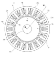
- FIG. 3 is a front sectional view showing the electric motor of FIG. 2.
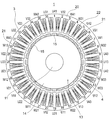
- FIG. 4 is a front sectional view showing the stator of FIG. 3.
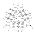
- It is a circuit diagram which shows the armature winding of FIG.
- It is a circuit diagram which shows the electric motor and ECU of FIG.
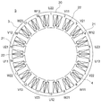
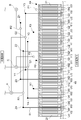
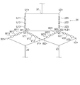
- FIG. 2 is a connection explanatory diagram of armature windings of the electric motor of FIG. 1.
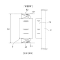
- FIG. 4 is a cross-sectional view taken along line VIII-VIII in FIG. 3. It is principal part sectional drawing which shows the conventional electric motor.
- FIG. 13 is a connection explanatory diagram of armature windings of the electric motor of FIG. 12. It is explanatory drawing which shows the strength of the magnetomotive force which the coil part which comprises the 2nd U-phase winding part of the electric motor of Embodiment 4 of this invention generate
- FIG. 1 is a configuration diagram showing an electric power steering device for an automobile equipped with the electric motor 1 according to Embodiment 1 of the present invention
- FIG. 2 is a cross-sectional view showing the electric drive device 100 of FIG. 1
- FIG. 2 is a front sectional view showing the electric motor 1 of FIG. 2
- FIG. 4 is a front sectional view showing the stator 5 of FIG.
- the electric power steering apparatus includes an electric drive device 100 including an electric motor 1 that is a rotating electric machine and an ECU 2 (Electric Control Unit) 2.
- ECU 2 Electronic Control Unit
- a driver steers a steering wheel (not shown), and the torque is transmitted to the shaft 101 via a steering shaft (not shown).
- the torque detected by the torque sensor 102 is converted into an electric signal and transmitted to the ECU 2 through the first connector 103 through a cable (not shown).
- vehicle information such as vehicle speed is converted into an electrical signal and transmitted to the ECU 2 via the second connector 105.
- the ECU 2 calculates necessary assist torque from the vehicle information such as the torque and the vehicle speed, and supplies current to the electric motor 1 arranged in parallel with a rack shaft (not shown) in the housing 108 through an inverter.
- the power supply to the ECU 2 is sent from the battery or alternator via the power connector 106.
- the torque generated by the electric motor 1 generates a thrust that is decelerated by a gear box 107 containing a belt (not shown) and a ball screw (not shown) and moves the rack shaft in the direction of the arrow d. Assist.
- the tie rod 109 moves and the tire can be steered to turn the vehicle.
- the driver is assisted by the torque of the electric motor 1 and can turn the vehicle with a small steering force.
- the rack boot 110 is provided so that foreign matter does not enter the apparatus.
- the electric motor 1 of the electric drive device 100 covers a stator 5, a cylindrical frame 6 in which the stator 5 is fixed to an inner wall surface, and one side opening of the frame 6 fixed with a plurality of bolts 8.
- a housing 7 and a rotor 13 are provided.
- the stator 5 has a stator core 3 configured by laminating magnetic core sheets such as electromagnetic steel plates, and an armature winding 4 housed in the stator core 3.
- the rotor 13 includes a shaft 11 supported at both ends by a first bearing 9 fitted to the housing 7 and a second bearing 10 fitted to the wall 12, and rotation through which the shaft 11 has passed.
- the permanent magnet 15 may be covered with a cylindrical cover made of a nonmagnetic material such as stainless steel or aluminum for protecting the permanent magnet 15 and preventing scattering.
- the ECU 2 of the electric drive device 100 has a power feeding unit 16 connected to the armature winding 4, and supplies U-phase, V-phase, and W-phase three-phase alternating currents to the armature winding 4 through the power feeding unit 16.
- the rotor 13 rotates.
- the side connected to the power feeding part 16, that is, the ECU 2 side is the power feeding part side of the armature winding 4
- the side opposite to the power feeding part 16 that is, the pulley 17 side is the side opposite to the power feeding part of the armature winding 4.
- the electric motor 1 and the ECU 2 are integrally arranged in the axial direction of the shaft 11.
- the present invention is not limited to this, and the ECU 2 may be arranged in the radial direction of the electric motor 1.
- the electric motor 1 and the ECU 2 may be separate.
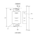
- stator axial direction length L the length from one coil end 50 or the end face of the connecting wire of the electric motor 1 to the other coil end 50 or the end face of the connecting wire.
- the stator core 3 of the stator 5 has an annular core back 20 and a total of 18 teeth 21 extending from the core back 20 in the inner diameter direction. A slot 22 is provided between adjacent teeth 21. Is formed.
- the armature winding 4 of the stator 5 is configured by winding a conductive wire around each tooth 21 in a concentrated manner. 3 and 4, the insulator provided between the armature winding 4 and the stator core 3 is omitted for simplicity.
- numbers 1 to 18 are assigned to the teeth 21 in FIG.
- a wire in which a conductive wire is intensively wound around each of the teeth 21 of the armature winding 4 is hereinafter referred to as a “coil portion”. Further, in FIG.
- the coil portions provided in each tooth 21 are represented by numbers for convenience so that the coil portions of the three phases U, V, and W can be recognized.
- U phase is 6 coil parts of U11, U12, U13, U21, U22, U23
- V phase is 6 coil parts of V11, V12, V13, V21, V22, V23
- W phase is W11, W12, W13, W21, W22, W23, each of which is composed of six coil portions, and as shown in FIG.
- each coil portion corresponds to each of the numbers 1 to 18 of the teeth 21 in the clockwise direction, U22, V11, V21, W12, U21, U11, V22, W13, W23, U12, V23, V13, W22, U13, U23, V12, W21, W11 are arranged in this order.
- FIG. 5 is a winding circuit diagram showing the armature winding 4 of the electric motor 1.
- the armature winding 4 includes a first armature winding portion 23 and a second armature winding portion 24.
- the first armature winding portion 23 includes a first U-phase winding portion U1, a first V-phase winding portion V1, and a first W-phase winding portion W1.
- the first U-phase winding portion U1 is an in-phase winding portion in which U11, U12 and U13, which are in-phase coil portions, are connected in series.
- the first V-phase winding portion V1 is an in-phase winding portion in which V11, V12, and V13, which are in-phase coil portions, are connected in series.
- the first W-phase winding portion W1 is an in-phase winding portion in which W11, W12, and W13 that are in-phase coil portions are connected in series.
- the second armature winding portion 24 includes a second U-phase winding portion U2, a second V-phase winding portion V2, and a second W-phase winding portion W2.
- the second U-phase winding portion U2 is an in-phase winding portion in which U21, U22 and U23 which are in-phase coil portions are connected in series.
- the second V-phase winding portion V2 is an in-phase winding portion in which V21, V22, and V23, which are in-phase coil portions, are connected in series.
- the second W-phase winding portion W2 is an in-phase winding portion in which W21, W22, and W23 that are in-phase coil portions are connected in series.
- the adjacent coil portions U11, U12, U13, U21, U22, U23, V11, V12, V13, V21, V22, V23, W11, W12, W13, W21, W22, and W23 are connected via a crossover 49.
- the lead wires 51 are led out from both ends of each in-phase winding portion U1, U2, V1, V2, W1, W2.
- the first U-phase winding portion U1 and the second U-phase winding portion U2 are connected in a parallel circuit via a lead wire 51, and the first V-phase winding portion V1 and the second V-phase winding portion are connected.
- the line portion V2 is connected in a parallel circuit via the lead wire 51, and the first W-phase winding portion W1 and the second W-phase winding portion W2 are connected in a parallel circuit via the lead wire 51. It is connected.
- the armature windings 4 are connected by ⁇ connection connection portions A, B, and C to form a ⁇ connection.
- FIG. 6 is a circuit diagram of the electric motor 1 and the ECU 2.
- the ECU 2 includes a single inverter 28, and supplies three-phase currents from the inverter 28 to the first armature winding portion 23 and the second armature winding portion 24.
- the ECU 2 is supplied with DC power from a power source 29 such as a battery, and is connected to a power relay 31 through a coil 30 for noise removal.
- the power source 29 is depicted as if inside the ECU 2, but in reality, power is supplied from an external power source such as a battery via a connector.
- One power supply relay 31 is provided and is composed of two MOS-FETs. When a failure occurs, the power supply relay 31 is opened so that an excessive current does not flow.
- the power supply 29, the coil 30, and the power supply relay 31 are connected in this order, but it goes without saying that the power supply relay 31 may be provided closer to the power supply 29 than the coil 30.
- the capacitor 33 is a smoothing capacitor. Further, although it is constituted by one capacitor 33 in FIG. 6, it goes without saying that a plurality of capacitors may be connected in parallel.
- the inverter 28 is configured by a bridge using six MOS-FETs, a first MOS-FET 34 and a second MOS-FET 35 are connected in series, and a third MOS-FET 36 and a fourth MOS-FET 37 are connected.
- the fifth MOS-FET 38 and the sixth MOS-FET 39 are connected in series, and the three sets of MOS-FETs are connected in parallel.
- the lower three second MOS-FETs 35, the fourth MOS-FET 37, and the sixth MOS-FET 39 GND (ground) side each have a first shunt 40, Two shunts 41 and a third shunt 42 are connected to each other.
- the shunts 40, 41, and 42 have shown three examples, two shunts may be used, and current detection is possible even with one shunt. Needless to say, it may be.
- the current is supplied to the electric motor 1 side between the first U-phase winding U1 of the electric motor 1 and the first MOS-FET 34 and the second MOS-FET 35 through the power feeding unit 16 and the first MOS-FET 34.
- the first V-phase winding portion V1 and the second V-phase winding of the electric motor 1 through the power feeding portion 16 from between the third MOS-FET 36 and the fourth MOS-FET 37 to the second U-phase winding portion U2.
- Part V2 is supplied from between the fifth MOS-FET 38 and the sixth MOS-FET 39 to the first W-phase winding part W1 and the second W-phase winding part W2 of the electric motor 1 through the power feeding part 16 respectively.
- the electrical connection between the electric motor 1 and the ECU 2 is a total of three locations for three phases, but is divided into a first armature winding portion 23 and a second armature winding portion 24 inside the electric motor 1.
- the phase current of the electric motor 1 is large, if the number of parallel circuits is small, the wire diameter of the coil becomes too large, and the workability becomes extremely low when winding the teeth 21 with concentrated winding.
- the armature winding 4 of the first embodiment is configured by a parallel circuit of the first armature winding portion 23 and the second armature winding portion 24, one armature winding is provided.
- the wire diameter of the coil can be reduced.
- the electric motor 1 in which the stator core 3 has a diameter of about 80 mm to 90 mm since a conducting wire having a diameter of about 1 mm can be used, the winding workability is high and it is suitable for mass production.
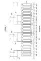
- FIG. 7 is a connection explanatory diagram of the armature winding 4 and includes 18 coil portions U11, U12, U13, U21, U22, U23, V11, V12, V13, V21, V22, V23, W11, W12, W13, It is a figure which shows how W21, W22, and W23 are electrically connected.
- the eighteen squares represent the teeth 21 from No. 1 to No. 18.
- Coil portions U11, U12, and U13 are continuously connected in series to form a first U-phase winding portion U1. At this time, in U12, the winding direction of the conducting wire is opposite to U11 and U13.
- the coil portions U21, U22, and U23 are continuously connected in series to form a second U-phase winding portion U2.
- the winding direction of the conducting wire is opposite to U21 and U23.
- Coil portions V11, V12, and V13 are continuously connected in series to form a first V-phase winding portion V1.
- the coil parts V21, V22, and V23 are continuously connected in series to form a second V-phase winding part V2.
- the winding direction of a conducting wire is opposite to V21 and V23.
- Coil portions W11, W12, and W13 are continuously connected in series to form a first W-phase winding portion W1. At this time, in W12, the winding direction of the conducting wire is opposite to W11 and W13. In addition, the coil parts W21, W22, and W23 are continuously connected in series to form a second W-phase winding part W2. At this time, in W22, the winding direction of the conducting wire is opposite to W21 and W23.
- the three in-phase coil portions on the series circuit are configured by jumping the three teeth 21 in one direction and winding the conductive wire around the fourth tooth 21, respectively.
- the connecting wire 49 can be shortened, and the electrical resistance can be reduced.
- the in-phase coil portions of the pair of in-phase winding portions are arranged adjacent to each other in the circumferential direction of the stator core 3, and the coil portions of the respective in-phase winding portions are The stator core 3 is disposed on the fourth tooth 21 so as to jump over the three teeth 21 in the clockwise direction and the counterclockwise direction, respectively.
- the coil portion U11 of the 14th first U-phase winding portion U1 is continuously connected to the 10th U12 and the 6th U13 via the crossover wire 49, respectively.
- the coil portion U21 of the fifteenth second U-phase winding portion U2 adjacent to U11 is continuously connected to the first U22 and the fifth U23 via the crossover wire 49, respectively.
- the coil portion V11 of the second first V-phase winding portion V1 is continuously connected to the sixteenth V12 and the twelfth V13 via the crossover wire 49, respectively.
- the coil portion V21 of the third second V-phase winding portion V2 adjacent to V11 is continuously connected to the seventh V22 and the eleventh V23 via the connecting wire 49, respectively.
- the W-phase coil portion W11 of the eighth first W-phase winding portion W1 is continuously connected to the fourth W12 and the eighteenth W13 via the crossover wire 49, respectively.
- the coil portion W21 of the ninth second W-phase winding portion W2 adjacent to W11 is continuously connected to the thirteenth W22 and the seventeenth W23 via the connecting wire 49, respectively.
- the lead wire 51 led out from U11 and U13 is drawn out in one axial direction, and U11, U12, and U13 are continuously connected in the other axial direction via the crossover wire 49. Is done.
- the lead wire 51 led out from U 21 and U 23 is drawn out in one axial direction, and U 21, U 22, and U 23 are continuously connected in the other axial direction via the crossover wire 49.
- the lead wire 51 led out from V11 and V13 is drawn out in one axial direction, and V11, V12, and V13 are continuously connected in the other axial direction via the crossover wire 49.
- the lead wire 51 derived from V21 and V23 is drawn out in one axial direction, and V21, V22, and V23 are continuously connected in the other axial direction via the crossover wire 49.
- the lead wire 51 led out from W11 and W13 is drawn out in one axial direction, and W11, W12, and W13 are continuously connected in the other axial direction via the crossover wire 49.
- the lead wire 51 derived from W21 and W23 is drawn out in one axial direction, and W21, W22, and W23 are continuously connected in the other axial direction via the crossover wire 49.
- the lead wire 51 includes the first and second phase winding portions U1, U2, V1, V2, W1, and W2 that are configured by the series circuits. Twelve electric motors 1 come out in the axial direction from the winding start and winding end of the conductor. Of the coil portions wound around the stator core 3, there are two in-phase coil portions such as U11 and U21, U13 and U23, V11 and V21, V13 and V23, W11 and W21, and W13 and W23.
- the lead-out line 51 comes out from two adjacent locations.
- the coil portions U11, U13, V11, V13, W11, and W13 are the first coil portions, and in the other in-phase winding portions U2, V2, and W2, the coil portions U21, U23, V21, V23, W21, and W23 from which the lead wire 51 is drawn are provided.
- the first coil portion is disposed adjacent to the second coil portion in the circumferential direction of the stator core 3. Further, the phase of the first coil portion is in phase with the phase of the second coil portion disposed adjacent to the first coil portion.
- the crossover wire 49 that connects the in-phase winding portions is drawn out to the other in the axial direction.
- X1 is the parallel circuit connection part which connected U11 and U21 which adjoin the circumferential direction.
- X2 is a parallel circuit connection unit that connects U13 and U23 adjacent in the circumferential direction.
- Y1 is a parallel circuit connecting portion that connects V11 and V21 adjacent in the circumferential direction.
- Y2 is a parallel circuit connection unit that connects V13 and V23 adjacent in the circumferential direction.
- Z1 is a parallel circuit connection portion Z1 in which W11 and W21 adjacent in the circumferential direction are connected.
- Z2 is a parallel circuit connection portion Z2 in which W13 and W23 adjacent in the circumferential direction are connected.
- the electric motor 1 is a three-phase two-parallel electric motor 1 having six parallel circuit connections X1, X2, Y1, Y, Z1, and Z2. Of these six parallel circuit connection parts X1, X2, Y1, Y, Z1, Z2, by connecting the parallel circuit connection parts X1, X2, Y1, Y, Z1, Z2 of different phases adjacent in the circumferential direction,
- the child winding 4 constitutes a ⁇ connection. That is, A is a ⁇ connection connection part connecting the parallel circuit connection part Y2 and the parallel circuit connection part Z1 adjacent in the circumferential direction, and B is a parallel circuit connection part X1 and the parallel circuit connection part Z2 adjacent in the circumferential direction. , And C is a ⁇ connection connection part connecting the parallel circuit connection part X2 and the parallel circuit connection part Y1 adjacent in the circumferential direction.
- the ⁇ connection connection portions A, B, and C are supplied with power from the external power supply unit 16 and are driven.
- the power feeding unit 16 and the parallel circuit connection units X1, X2, Y1, Y, Z1, Z2, and the ⁇ connection connection units A, B, and C are separate members, the power feeding unit 16 is connected to the parallel circuit connection unit. Or you may serve as (DELTA) connection connection part or both.
- FIG. 8 is a cross-sectional view taken along the line VIII-VIII in FIG. 3, and FIG. 9 is a cross-sectional view of a portion corresponding to the cross section of FIG.
- the coil portions for example, U 12 and U 13 of the first U-phase winding portion U 1 on the same series circuit are connected via the crossover wire 49 on the power feeding portion side.
- the crossover line 49 intersects.
- the slots 22 of the stator core 3 generally have a trapezoidal shape with a short side on the inner peripheral side and a long side on the outer peripheral side.
- this empty space S1 is a dead space, and as a result, the length L1 of the electric motor 1 in the stator axial direction is increased.
- the connecting wire 49 connecting the in-phase coil portions connected on the series circuit is connected on the pulley 17 side.
- S1 can be used effectively, and as a result, the stator axial direction length L2 of the electric motor 1 is shorter than L1.
- the first U-phase winding portion U1 that forms a series circuit with U11, U12, and U13, and the second U-phase winding portion U2 that forms a series circuit with U21, U22, and U23 are pulleys. Since there is no place where the crossover lines 49 intersect each other on the 17th side, the winding work is facilitated and the workability is improved.
- connection portions X1, X2, Y1, Y2, Z1, and Z2 are connected to each other and the ⁇ connection connection portions A, B, and C are connected to each other, a three-phase two-parallel ⁇ connection can be configured.
- the length L2 of the stator 1 in the axial direction of the stator 1 can be shortened, and a small and lightweight electric motor 1 can be obtained.
- the coil part of each in-phase connected to a series circuit is wound continuously and the crossover wire 49 is arrange
- a member such as a connection plate is provided and the connecting wire is arranged.
- the space factor can be improved and the torque can be improved.
- the number of turns of the lead wires U12, U22, V12, V22, W12, and W22 that are in-phase coil portions without the lead wire 51 is T (T is a natural number).
- FIG. FIG. 10 is a longitudinal sectional view showing the electric motor 1 according to the second embodiment of the present invention.
- the number of poles of the rotor 13 is 28 and the number of teeth 21 of the stator core 3 is 36.
- the rotor 13 is provided with a rotor core 14 on the outer side of the shaft 11 and the shaft 11, and 28 permanent magnets 15 are attached to the outer peripheral surface of the rotor core 14 at equal intervals in the circumferential direction.
- a non-magnetic material such as stainless steel or aluminum may be covered outside the permanent magnet 15 with a cylindrical cover for protection of the permanent magnet 15 and prevention of scattering.
- the stator 5 includes a stator core 3 and an armature winding 4 wound around the stator core 3.
- the stator core 3 has an annular core back 20 and a total of 36 teeth 21 extending from the core back 20 in the inner diameter direction and forming slots 22.
- the armature winding 4 is configured by each coil portion in which a conductive wire is intensively wound around each tooth 21.
- an insulator provided between the armature winding 4 and the stator core 3 and a frame provided on the outer periphery of the stator core 3 are omitted.
- the teeth 21 are assigned numbers 1 to 36.
- Each coil portion formed by concentrically winding a conductive wire around each of the teeth 21 is numbered for convenience so that the coil portion of any of the three phases U, V, and W can be identified. ing.
- Each of the U, V, and W phases is composed of 12 coil portions of U11, U12, U13, U21, U22, U23, U31, U32, U33, U41, U42, and U43, and the V phase is V11, V12.
- W phase is W11, W12, W13, W21, W22, W23, W31, W32, W33, W41 , W42, and W43, respectively.
- the coil portions of each phase correspond to the numbers 1 to 36 of the teeth 21, respectively, U41, V32, W41, W31, U42, V31, V41, W32, U43, U13, V42, W33, W23, U12, V43, V13, W2, U11, U21, V12, W21, W11, U2, V11, V21, W12, U23, U33, V2, W13, W43, U32, V23, V33, W42, U31 It becomes the structure arranged in order.
- FIG. 11 is a connection explanatory diagram of the armature winding 4 and shows how the 36 coil portions are electrically connected.
- the 36-lined squares represent the teeth 21 from No. 1 to No. 36, and the coil portions wound around the teeth 21 are U41, V32, W41, W31, U42, V31, V41, W32, U43, U13, V42, W33, W23, U12, V43, V13, W2, U11, U21, V12, W21, W11, U22, V11, V21, W12, U23, U33, V22, W13, W43, U32, V23, V33, W42, and U31 are shown.
- U11, U12, and U13 are connected in series to form a first U-phase winding portion U1 that is an in-phase winding portion.
- U12 the winding direction of the conducting wire is opposite to U11 and U13.
- U21, U2 and U23 are connected in series to form a second U-phase winding portion U2 which is an in-phase winding portion.
- U22 the winding direction of the conducting wire is opposite to U21 and U23.
- U31, U32, and U33 are connected in series to form a third U-phase winding portion U3 that is an in-phase winding portion.
- U32 the winding direction of the conducting wire is opposite to U31 and U33.
- U41, U42, and U43 are connected in series to form a fourth U-phase winding portion U4 that is an in-phase winding portion.
- U42 the winding direction of the conducting wire is opposite to U41 and U43.
- V11, V12, and V13 are connected in series to form a first V-phase winding portion V1 that is an in-phase winding portion.
- V12 the winding direction of the conducting wire is opposite to V11 and V13.
- V21, V22, and V23 are connected in series to constitute a second V-phase winding portion V2 that is an in-phase winding portion.
- V22 the winding direction of a conducting wire is opposite to V21 and V23.
- V31, V32, and V33 are connected in series to form a third V-phase winding portion V3 that is an in-phase winding portion.
- V32 the winding direction of the conducting wire is opposite to that of V31 and V33.
- V41, V42, and V43 are connected in series to form a fourth V-phase winding portion V4 that is an in-phase winding portion.
- V42 the winding direction of the conducting wire is opposite to that of V41 and V43.
- W11, W12, and W13 are connected in series to form a first W-phase winding portion W1 that is an in-phase winding portion.
- W12 the winding direction of the conducting wire is opposite to W11 and W13.
- W21, W22, and W23 are connected in series to form a second W-phase winding portion W2 that is an in-phase winding portion.
- W22 the winding direction of the conducting wire is opposite to W21 and W23.
- W31, W32, and W33 are connected in series to form a third W-phase winding portion W3 that is an in-phase winding portion.
- W32 the winding direction of the conducting wire is opposite to W31 and W33.
- W41, W42, and W43 are connected in series to form a fourth W-phase winding portion W4 that is an in-phase winding portion.
- W42 the winding direction of the conducting wire is opposite to W41 and W43.
- the first U-phase winding portion U1, the second U-phase winding portion U2, the third U-phase winding portion U3, and the fourth U-phase winding are the in-phase winding portions.
- Part U4 first V-phase winding part V1, second V-phase winding part V2, third V-phase winding part V3, fourth V-phase winding part V4, first W-phase winding Part W1, second W-phase winding part W2, third W-phase winding part W3 and fourth W-phase winding part W4, U1, U2, U3, W4, V1, V2, V3, V4, W1, W2, W3 and W4 are omitted.
- U 41, U 42, and U 43 are connected to the other in the axial direction via the connecting wire 49, with the lead wire 51 being drawn out in one axial direction of U 41 and U 43.
- V 1, V 11, V 12, and V 13 are connected to each other in the axial direction of V 11 and V 13, and a lead wire 51 is drawn out through the connecting wire 49.
- V 21, V 22, and V 23 are connected to each other in the axial direction of V 21 and V 23, and the lead line 51 is connected to the other in the axial direction via the connecting wire 49.
- V 31, V 32, and V 33 are connected to each other in the axial direction of V 31 and V 33, and the connecting line 49 is connected to the other in the axial direction via the connecting wire 49.
- V 41, V 42, and V 43 are connected to one end in the axial direction of V 41 and V 43, and the other end in the axial direction is connected via the connecting wire 49.
- W11, W12, and W13 are connected to the other in the axial direction via the connecting wire 49, with the lead wire 51 drawn out in one of the axial directions of W11 and W13.
- W21, W22, and W23 are connected to one end in the axial direction of W21 and W23, connected to the other in the axial direction via the jumper wire 49
- W3 In the third W-phase winding portion W3, W31, W32, and W33 are connected to the other in the axial direction via the connecting wire 49, with the lead wire 51 drawn out in one axial direction of W31 and W33.
- W41, W42, and W43 In the fourth W-phase winding W4, W41, W42, and W43 are connected to the other in the axial direction via the connecting wire 49, with the lead wire 51 being drawn out in one of the axial directions of W41 and W43.
- 24 lead wires 51 come out as a whole in the axial direction from the winding start and winding end of the conducting wire connected to each series circuit. That is, among the coil parts wound around the stator core 3, U11 and U21, U23 and U33, U31 and U41, U43 and U13, V11 and V21, V23 and V33, V31 and V41, V43 and V13, W11 and
- the lead wire 51 comes out from a location where two in-phase coil portions are adjacent in the circumferential direction, such as W21, W23 and W33, W31 and W41, and W43 and W13.
- one of the in-phase winding portions has coil portions U11 and U23 from which the lead wire 51 is drawn.
- U31, U43, V11, V23, V31, V43, W11, W23, W31, W43 are the first coil portions
- the coil portions U21, U33 from which the lead wire 51 is drawn U41, U13, V21, V33, V41, V13, W21, W33, W41, W13 are the second coil parts
- the first coil part is the second coil part in the circumferential direction of the stator core 3.
- each phase is composed of a set of four parallel circuits.
- U11 and U21 adjacent in the circumferential direction are connected to form a primary parallel circuit connection portion X2.
- U23 and U33 adjacent in the circumferential direction are connected to form a primary parallel circuit connection portion X3.
- U31 and U41 which adjoin the circumferential direction are connected, and let it be the primary parallel circuit connection part X4.
- U43 and U13 adjacent in the circumferential direction are connected to form a primary parallel circuit connection portion X1.
- V11 and V21 adjacent in the circumferential direction are connected to form a primary parallel circuit connection portion Y2.
- V23 and V33 which are adjacent in the circumferential direction are connected to form a primary parallel circuit connecting portion Y3.
- V31 and V41 adjacent in the circumferential direction are connected to form a primary parallel circuit connection portion Y4.
- V43 and V13 adjacent in the circumferential direction are connected to form a primary parallel circuit connection portion Y1.
- W11 and W21 adjacent in the circumferential direction are connected to form a primary parallel circuit connection portion Z2.
- the electric motor 1 in the second embodiment is a three-phase four-parallel electric motor 1 having 12 primary parallel circuit connection portions. Of these twelve primary parallel circuit connections X1, X2, X3, X4, Y1, Y2, Y3, Y4, Z1, Z2, Z3, Z4, a primary parallel circuit of the same phase arranged at every mechanical angle of 180 degrees Connect the connection.
- the primary parallel circuit connection unit X1 and the primary parallel circuit connection unit X3 are connected to form a secondary parallel circuit connection unit P2. Further, the primary parallel circuit connection unit X2 and the primary parallel circuit connection unit X4 are connected to form a secondary parallel circuit connection unit P1. Further, the primary parallel circuit connection unit Y1 and the primary parallel circuit connection unit Y3 are connected to form a secondary parallel circuit connection unit Q2. Further, the primary parallel circuit connection unit Y2 and the primary parallel circuit connection unit Y4 are connected to form a secondary parallel circuit connection unit Q1. Further, the primary parallel circuit connection part Z1 and the primary parallel circuit connection part Z3 are connected to form a secondary parallel circuit connection part R2. Further, the primary parallel circuit connection unit Z2 and the primary parallel circuit connection unit Z4 are connected to form a secondary parallel circuit connection unit R1.
- the ⁇ connection connection portion A, the ⁇ connection connection portion B, and the ⁇ connection connection portion C are supplied with power from the external power supply portion 16 and are driven.
- the power feeding section 16 and the primary parallel circuit connection sections X1, X2, X3, X4, Y1, Y2, Y3, Y4, Z1, Z2, Z3, Z4, secondary parallel circuit connection sections P1, P2, Q1, Q2, R1, R2, and ⁇ connection connection parts A, B, and C are separate members.
- the power supply unit 16 is either a primary parallel circuit connection part, a secondary parallel circuit connection part, or a ⁇ connection connection part, or It may also serve as all of them.
- the crossover wire 49 for configuring the four parallel circuits is necessary.
- the empty spaces S1 and S2 on the power feeding unit side and the counter feeding unit side are effectively used. Since it can be utilized, the stator axial direction length L can be reduced, the stator axial direction length L of the electric motor 1 can be shortened, and the small and lightweight electric motor 1 can be obtained.
- the number of magnetic poles is 14, and the number of teeth 21 is 18.
- the number of magnetic poles is 28 and the number of teeth 21 is 36.
- M (18 ⁇ 4)
- n and N 18n, where M is the number of magnetic poles, N is the number of teeth 21, and n is a natural number.
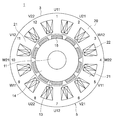
- FIG. 12 is a longitudinal sectional view showing the electric motor 1 according to the third embodiment of the present invention.
- the number of poles of the rotor 13 is 10, and the number of teeth 21 of the stator core 3 is 12.
- the rotor 13 includes a shaft 11, a rotor core 14 provided on the outer side of the shaft 11, and ten permanent magnets 15 attached to the outer peripheral surface of the rotor core 14 at equal intervals in the circumferential direction. is doing.
- the permanent magnet 15 may be covered with a cylindrical cover made of a nonmagnetic material such as stainless steel or aluminum to protect the permanent magnet 15 and prevent scattering.
- the stator 5 includes a stator core 3 and an armature winding 4 wound around the stator core 3.
- the stator core 3 has an annular core back 20 and twelve teeth 21 extending from the core back 20 in the inner diameter direction and forming slots 22.
- each tooth 21 has a flange that protrudes from the tip of the tooth 21 toward both sides in the circumferential direction, and the flanges of two adjacent teeth 21 are connected to each other.
- the armature winding 4 is configured by each coil portion in which a conductive wire is intensively wound around each tooth 21.
- an insulator provided between the armature winding 4 and the stator core 3 and a frame provided on the outer periphery of the stator core 3 are omitted.
- each coil portion formed by concentrically winding a conductive wire around each of the teeth 21 is numbered for convenience so that the coil portion of any of the three phases U, V, and W can be identified. ing.
- the U phase has four coil portions U11, U12, U21, and U22
- the V phase has four coil portions V11, V12, V21, and V22
- the W phase has four pieces W11, W12, W21, and W22. It is comprised from each coil part. As shown in FIG.
- the coil portions of each phase correspond to the numbers 1 to 12 of the teeth 21, respectively, U11, U21, W12, W22, V11, V21, U12, U22, W11, W21, V12, They are arranged in the order of V22.
- FIG. 13 is a winding circuit diagram showing the armature winding 4 of the electric motor.
- the armature winding 4 is composed of a first armature winding portion 23 and a second armature winding portion 23.
- the first armature winding portion 23 includes a first U-phase winding portion U1, a first V-phase winding portion V1, and a first W-phase winding portion W1.
- the first U-phase winding portion U1 is an in-phase winding portion in which U11 and U12, which are in-phase coil portions, are connected in series.
- the first V-phase winding portion V1 is an in-phase winding portion in which V11 and V12 that are in-phase coil portions are connected in series.
- the first W-phase winding portion W1 is an in-phase winding portion in which W11 and W12, which are in-phase coil portions, are connected in series.
- the second armature winding portion includes a second U-phase winding portion U2, a second V-phase winding portion V2, and a second W-phase winding portion W2.
- the second U-phase winding portion U2 is an in-phase winding portion in which U21 and U22, which are in-phase coil portions, are connected in series.
- the second V-phase winding portion V2 is an in-phase winding portion in which V21 and V22 that are in-phase coil portions are connected in series.
- the second W-phase winding portion W2 is an in-phase winding portion in which W21 and W22, which are in-phase coil portions, are connected in series.
- the adjacent coil parts U11, U12, U21, U22, V11, V12, V21, V22, W11, W12, W21, and W22 are connected to each other via a jumper wire 49, and each in-phase winding part U1, Lead lines 51 are led out from both ends of U2, V1, V2, W1, and W2, respectively.
- the first U-phase winding portion U1 and the second U-phase winding portion U2 are connected in a parallel circuit via a lead wire 51 drawn in one of the axial directions, and similarly, the first V-phase winding portion U1 is connected to the first V-phase winding portion U1.
- Winding portion V1 and second V-phase winding portion V2 are connected in a parallel circuit via lead wire 51 drawn in one of the axial directions, and the first W-phase winding portion W1 and the second V-phase winding portion V2
- the W-phase winding portion W2 is connected in a parallel circuit via a lead wire 51 drawn to one side in the axial direction.
- the armature windings 4 are connected by ⁇ connection connection portions A, B, and C to form a ⁇ connection.
- FIG. 14 is a connection explanatory diagram of the armature winding 4 and shows how the twelve coil portions are electrically connected.
- the twelve quadrangles represent the teeth 21 from No. 1 to No. 12, and coil portions wound around the teeth 21 are U11, U21, W21, W22, V11, V12, U21, U22, W11, W12, V21, and V22 are shown.
- U11 and U12 are connected in series to form a first U-phase winding portion U1 that is an in-phase winding portion. At this time, as for U11 and U12, the winding direction of conducting wire is reverse.
- U21 and U22 are connected in series to form a second U-phase winding portion U2 that is an in-phase winding portion.
- the winding direction of a conducting wire is the reverse direction.
- V11 and V12 are connected in series to form a first V-phase winding portion V1 that is an in-phase winding portion.
- V11 and V12 the winding direction of a conducting wire is reverse.
- V21 and V22 are connected in series to constitute a second V-phase winding portion V2 that is an in-phase winding portion.
- W11 and W12 are connected in series to form a first W-phase winding portion W1 that is an in-phase winding portion.
- the winding direction of a conducting wire is reverse.
- W21 and W22 are connected in series to form a second W-phase winding portion W2 that is an in-phase winding portion.
- the winding direction of the conducting wire is opposite.
- the first U-phase winding portion U1, the second U-phase winding portion U2, the first V-phase winding portion V1, and the second V-phase winding which are in-phase winding portions.
- the reference numerals U1, U2, V1, V2, W1, and W2 of the portion V2, the first W-phase winding portion W1, and the second W-phase winding portion W2 are omitted.
- V 21 and V 22 are connected to each other in the axial direction via the connecting wire 49, with the lead wire 51 drawn out in one axial direction.
- W11 and W12 are connected to each other in the axial direction via the connecting wire 49, with the lead wire 51 drawn out in one axial direction.
- W 21 and W 22 are connected to each other in the axial direction via the connecting wire 49, with the lead wire 51 drawn out in one axial direction.
- twelve lead wires 51 come out as a whole in one axial direction from the winding start and winding end of the conducting wire connected to each series circuit. That is, of the coil parts wound around the stator core 3, there are two coil parts having the same phase in the circumferential direction, such as U11 and U21, U12 and U22, V11 and V21, V12 and V22, W11 and W21, and W12 and W22.
- the lead-out line 51 comes out from two adjacent locations.
- the coil portions U11, U12, V11, V12, W11, W12 are the first coil portions, and in the other in-phase winding portions U2, V2, W2, the coil portions U21, U22, V21, V22, W21, W22 from which the lead wire 51 is drawn are provided.
- the first coil portion is disposed adjacent to the second coil portion in the circumferential direction of the stator core 3. Further, the phase of the first coil portion is in phase with the phase of the second coil portion disposed adjacent to the first coil portion.
- the crossover wire 49 that connects the in-phase winding portions is drawn to the other in the axial direction.
- each phase is composed of a set of two parallel circuits.
- X1 is a parallel circuit connection part which connected U11 and U21 adjacent in the circumferential direction.
- X2 is a parallel circuit connection unit that connects U12 and U22 adjacent in the circumferential direction.
- Y1 is a parallel circuit connecting portion that connects V11 and V21 adjacent in the circumferential direction.
- Y2 is a parallel circuit connection unit that connects V12 and V22 adjacent in the circumferential direction.
- Z1 is a parallel circuit connection portion Z1 in which W11 and W21 adjacent in the circumferential direction are connected.
- Z2 is a parallel circuit connection portion Z2 connecting W12 and W22 adjacent in the circumferential direction.
- the electric motor according to Embodiment 3 is a three-phase two-parallel electric motor having six parallel circuit connections X1, X2, Y1, Y, Z1, and Z2. Of these six parallel circuit connection parts X1, X2, Y1, Y, Z1, Z2, by connecting the parallel circuit connection parts X1, X2, Y1, Y, Z1, Z2 of different phases adjacent in the circumferential direction,
- the child winding 4 constitutes a ⁇ connection. That is, A is a ⁇ connection connection part connecting the parallel circuit connection part Y2 and the parallel circuit connection part Z1 adjacent in the circumferential direction, and B is a parallel circuit connection part X1 and the parallel circuit connection part Z2 adjacent in the circumferential direction. , And C is a ⁇ connection connection part connecting the parallel circuit connection part X2 and the parallel circuit connection part Y1 adjacent in the circumferential direction.
- the ⁇ connection connection portions A, B, and C are supplied with power from an external power supply unit and are driven.
- the power feeding unit and the parallel circuit connecting parts X1, X2, Y1, Y, Z1, Z2, and the ⁇ connection connecting parts A, B, and C are separate members, but the power feeding part is a parallel circuit connecting part or ⁇ You may serve as a connection part or both.
- the crossover wire 49 that connects the in-phase coil portions connected on the series circuit is connected on the pulley 17 side, the empty space S1 on the counter-feeding portion side is effectively used.
- the length L2 of the electric motor 1 in the stator axial direction is shorter than the length L1.
- connection portions X1, X2, Y1, Y2, Z1, and Z2 are connected to each other and the ⁇ connection connection portions A, B, and C are connected to each other, a three-phase two-parallel ⁇ connection can be configured.
- the length L2 of the stator in the axial direction can be shortened, and a small and lightweight electric motor can be obtained.
- the coil part of each in-phase connected to a series circuit is wound continuously and the crossover wire 49 is arrange
- the number of magnetic poles is 10 and the number of teeth 21 is 12. However, when the number of magnetic poles and the number of teeth 21 are generalized from the electric motor of the third embodiment, the number of magnetic poles is M and the number of teeth.
- N is a natural number and n is a natural number
- M (12 ⁇ 2)
- N 12n.
- Embodiment 4 FIG.
- the number of turns of the lead wires U12, U22, V12, V22, W12, and W22, which are coil portions without the lead wire 51, of the coil portions constituting each series circuit is set to T1 (T1 Is a natural number), among the coil parts constituting each series circuit, the coil parts having lead wires 51 are U11, U13, U21, U23, V11, V13, V21, V23, W11, W13, W21, W13.
- T2 is an odd multiple of 0.5
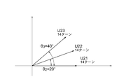
- FIG. 15 is a vector diagram showing the electrical angle phases of the phase coil portions U21, U22, U23 in the second U-phase winding portion U2 that is the in-phase winding portion of the fourth embodiment.
- the length indicates the strength of the magnetomotive force generated by the coil portion wound around each tooth 21, and the vector angle indicates the electrical angle phase of the coil portion wound around each tooth 21. Since the magnetomotive force generated by the coil portion is proportional to the product of the number of turns of the conductor and the magnitude of the current, the length of the vector in the figure is proportional to the number of turns.
- the coil portions U21, U22, U23 are sequentially arranged in the circumferential direction of the stator 5 with an electrical angle phase difference of 20 °. Therefore, the coil portions U21 and U23 have the largest electrical angle phase difference, and the electrical angle phase difference is 40 °.
- the electrical angle ⁇ 0 ⁇ with respect to the coil portion U21
- the number of turns of the conducting wire of the coil portion U22 is a multi-turn coil larger than that of other coil portions connected in series, and the generated electromagnetic field is stronger than the coil portions U21 and U23.
- FIG. 16 shows magnetomotive force vectors generated in the coil portions U21, U2, and U23 in the second armature winding portion 24 having the same number of turns of the conducting wires of all the coil portions.
- the strength of the magnetomotive force generated by the U phase is expressed by the length of the composite vector. Therefore, in the electric motor 1 according to the fourth embodiment of the present invention, compared to the case where the number of turns of all the coil portions is equal, the vector in which the electrical angle phase is located at the center is increased, the combined vector length is increased, Strength can be increased. Thereby, the magnetic flux density between the magnetic space
- FIG. 17 is a connection explanatory diagram of the armature winding 4 in the electric motor 1 according to the fifth embodiment of the present invention, and shows how the 18 coil portions are electrically connected.
- FIG. 18 is a circuit diagram of the armature winding 4 in FIG. 17.
- the 18 squares arranged represent the teeth 21 from No. 1 to No. 18, and coil portions around which the conductive wires are wound around the teeth 21 are U22, V11, V21, W12, U23, U13. , V22, W11, W21, U12, V23, V13, W22, U11, U21, V12, W23, W13.
- U11, U22, and U13 having the same winding direction of the conducting wire are connected in series to form a first U-phase winding portion U1.
- the adjacent in-phase coil parts on the same series circuit are disposed on the fifth tooth 21 so as to jump over the four teeth 21.
- the second U-phase winding portion U2 configured by connecting U21, U12, and U23 in series, V11, V22, and V13 are connected in series, and the first V-phase winding portions V1, V21, V12, and V23 are connected in series.
- the second V-phase winding portion V2, W11, W22, and W13 are connected in series, and the first W-phase winding portion W1, and the second W that is connected in series with W11, W22, and W13.
- the winding direction of the conducting wire in each phase coil portion is the same for the phase winding portion W2, and adjacent in-phase coil portions on the same series circuit are
- the fifth teeth 21 are disposed so as to jump over the four teeth 21 from each other.
- first U-phase winding portion U1 and the second U-phase winding portion U2 are disposed at a position shifted from each other by a mechanical angle of 180 degrees, the first U-phase winding portion U1 and the second U-phase winding portion U1 This is because the electromagnetic force when the current of the U-phase winding portion U2 becomes unbalanced can be further reduced.
- the first V-phase winding portion V1, the second V-phase winding portion V2, the first W-phase winding portion W1, and the second W-phase winding portion W2 are also the first U-phase winding portion U1. The arrangement is similar to that of the second U-phase winding portion U2.
- FIG. 19 is a connection explanatory diagram of the armature winding 4 in the electric motor 1 of the sixth embodiment of the present invention
- FIG. 20 is a front sectional view showing the electric motor 1 of the sixth embodiment of the present invention
- FIG. It is explanatory drawing explaining the circuit of the electric motor 1 and ECU2 in the form 6.
- the configuration of the electric motor 1 according to the sixth embodiment is different from the connection explanatory diagram of each drawn-out wire 51 as can be seen from the connection explanatory diagram of the armature winding 4 according to the first embodiment shown in FIG. These are the same as those in the first embodiment.
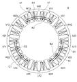
- coil portions U11 and U21, coil portions U13 and U23, coil portions V11 and V21, coil portions V13 and V23, coil portion W11, Lead wires 51 are led out from W21 and coil portions W13 and W23, respectively, and the coil portions U11 and V13 are connected to form a ⁇ connection connection portion C1.
- the coil portions U21 and V23 are connected to form a ⁇ connection connection portion C2.
- the coil portions W11 and U13 are connected to form a ⁇ connection connection portion B1.
- the coil portions W21 and U23 are connected to form a ⁇ connection connection portion B2.
- the coil portions V11 and W13 are connected to form a ⁇ connection connection portion A1.
- Coil portions V21 and W23 are connected to form a ⁇ connection connection portion A2.
- the ⁇ connection connection portion A ⁇ b> 1 is disposed closer to the outer periphery side of the electric motor 1 than the ⁇ connection connection portion A ⁇ b> 2.
- the ⁇ connection connection portion B1 is disposed on the outer peripheral side of the electric motor 1 with respect to the ⁇ connection connection portion B2.
- the ⁇ connection connection portion C1 is arranged on the outer peripheral side of the electric motor 1 with respect to the ⁇ connection connection portion C2.
- the ⁇ connection connection portion A1 is the ⁇ connection. It arrange
- positions (DELTA) connection connection part B1 to the inner periphery side of the electric motor 1 rather than (DELTA) connection connection part B2, and sets (DELTA) connection connection part C1 from (DELTA) connection connection part C2.
- the armature winding 4 of the electric motor 1 is a first electric machine constituted by a first U-phase winding portion U1, a first V-phase winding portion V1, and a first W-phase winding portion W1. From the secondary winding portion 23 and the second U-phase winding portion U2, the second V-phase winding portion V2, and the second armature winding portion 24 constituted by the second W-phase winding portion W2. Composed.
- the ECU 2 includes two first and second inverters 28A and 28B, and supplies three-phase currents to the two armature winding portions 23 and 24 from the respective inverters 28A and 28B.
- the ECU 2 is supplied with DC power from a power source 29 such as a battery, and is connected to power relays 31A and 31B via a coil 30 for noise removal.
- a power source 29 such as a battery
- the power source 29 is depicted as if inside the ECU 2, but in reality, power is supplied from an external power source such as a battery via a connector.
- the two power relays 31A and 31B are each composed of two MOS-FETs, and when a failure occurs, the power relays 31A and 31B are opened so that an excessive current does not flow.
- the power supply relays 31 ⁇ / b> A and 31 ⁇ / b> B are connected in the order of the power supply 29 and the coil 30, but it goes without saying that the power supply relays 31 ⁇ / b> A and 31 ⁇ / b> B may be provided closer to the power supply 29 than the coil 30.
- Capacitors 33A and 33B are smoothing capacitors. In FIG. 21, each capacitor is composed of one capacitor 33A and 33B, but it goes without saying that a plurality of capacitors may be connected in parallel.
- Each of the inverters 28A and 28B is constituted by a bridge using six MOS-FETs.
- a first MOS-FET 34A and a second MOS-FET 35A are connected in series
- a third MOS-FET 36A and a fourth MOS-FET 37A are connected in series
- a fifth MOS-FET 38A, A sixth MOS-FET 39A is connected in series.
- the three sets of MOS-FETs connected in series are connected in parallel.
- the first shunt 40A, the second shunt 41A, and the third shunt 40 are respectively provided on the GND (ground) side of the lower three second MOS-FETs 35A, fourth MOS-FET 37A, and sixth MOS-FET 39A.
- the shunt 42A is connected.
- shunts 40A, 41A, and 42A are used for detecting a current value.
- the shunt 40A, 41A, 42A showed three examples, since two shunts may be sufficient and an electric current detection is possible even if it is one shunt, such a structure Needless to say, it may be.
- the supply of current to the motor 1 side is performed between the first MOS-FET 34A and the second MOS-FET 35A through the power feeding unit 16 to the first U-phase winding unit U1 of the motor 1.
- the electric power is supplied to the first W-phase winding part W1 of the electric motor 1 through the power supply part 16, respectively.
- the second inverter 28B has the same configuration.
- the first MOS-FET 34B and the second MOS-FET 35B are connected in series, and the third MOS-FET 36B and the fourth MOS-FET 37B are connected in series.
- the fifth MOS-FET 38B and the sixth MOS-FET 39B are connected in series.
- the three sets of MOS-FETs connected in series are connected in parallel.
- the first shunt 40B, the second shunt 41B, and the third shunt are respectively provided on the GND (ground) side of the lower three second MOS-FETs 35B, fourth MOS-FET 37B, and sixth MOS-FET 39B.
- the shunt 42B is connected.
- shunts 40B, 41B, and 42B are used for detecting a current value.
- the shunts 40B, 41B, and 42B have shown three examples, two shunts may be used, and current detection is possible even with one shunt. Needless to say, it may be.
- the current is supplied to the motor 1 side from between the first MOS-FET 34B and the second MOS-FET 35B to the second U-phase winding unit U2 of the motor 1 through the power feeding unit 16.
- the electric power is supplied to the second W-phase winding part W2 of the electric motor 1 through the power supply part 16, respectively.
- the two inverters 28A and 28B are switched by sending a signal from the control circuit (not shown) to the MOS-FET according to the rotation angle detected by the rotation angle sensor 120 such as the MR sensor provided in the electric motor 1, A desired three-phase current is supplied to the first armature winding portion 23 and the second armature winding portion 24.
- the ⁇ connection connecting part A1, the ⁇ connection connecting part B1, and the ⁇ connection connecting part C1 shown in FIGS. 19 and 20 are connected to the first inverter 28A shown in FIG.
- the ⁇ connection connection part A2, the ⁇ connection connection part B2, and the ⁇ connection connection part C2 shown in FIGS. 19 and 20 are connected to the second inverter 28B shown in FIG.
- the electric power feeding part 16 and (DELTA) connection connection part A1, B1, C1, A2, B2, C2 were used as another member here, the electric power feeding part 16 may serve as the (DELTA) connection connection part.
- the two armature winding portions 23 and 24 are connected in parallel outside the motor 1, so that if the circuit is electrically independent even if a short circuit occurs inside the motor 1, it is normal. Since the inverters 28A and 28B and the armature winding portions 23 and 24 can generate torque, the effect of short circuit can be reduced. Further, when the electric motor 1 is driven by only one inverter 28, there is a problem that the arrangement of the armature windings 4 becomes unbalanced and vibration and noise of the electric motor 1 increase.
- the coil part that is a component of the first armature winding part 23 and the second electric machine is alternately arranged on each tooth 21 along the circumferential direction of the stator core 3, and the first armature in which the coil part is arranged in this way. Since the winding portion 23 and the second armature winding portion 24 are individually energized from the respective inverters 28A and 28B, vibration and noise of the electric motor 1 are reduced.
- each of the first armature winding portion 23 and the second armature winding portion 24 is similar to the electric motor 1 of the first embodiment. Since the coil portions are arranged 180 degrees symmetrical to each other, vibration and noise are reduced.
- FIG. 21 shows an example without a motor relay, but by providing a motor relay, it is possible to take measures such as reducing the brake torque by opening the motor relay in the event of a failure.
- the conductive wire of the coil portion in the middle of the three coil portions of the U-phase, V-phase and V-phase in-phase winding portions is different from the winding direction of the conducting wires of the other two coil portions.
- each of the U-phase, V-phase and V-phase in-phase winding portions 3 The coil winding directions of the three coil portions are the same in all three coils, and adjacent in-phase coil portions on the same straight circuit jump over the four teeth 21 and are arranged on the fifth tooth 21.
- FIG. 22 is a connection explanatory diagram of the armature winding 4 of the electric motor 1 according to the seventh embodiment of the present invention
- FIG. 23 is a front sectional view of the electric motor 1.
- the configuration of the electric motor 1 of the seventh embodiment is different from the connection object of each drawn-out wire 51 as can be seen from the connection explanatory diagram of the armature winding 4 of the first embodiment shown in FIG. These are the same as those in the first embodiment.
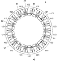
- this electric motor 1 two in-phase coil portions adjacent to each other in the circumferential direction of each phase, coil portions U11 and U21, coil portions U13 and U23, coil portions V11 and V21, coil portions V13 and V23, coil portions W11 and W21.
- the lead wires 51 are led out from the coil portions W13 and W23, respectively, and U11 and V13 are connected to form a ⁇ connection connection portion C1. Similarly, U21 and W23 are connected to form a ⁇ connection B2. Also, W11 and U13 are connected to form a ⁇ connection B1. Further, W21 and V23 are connected to form a ⁇ connection connection portion A2. Further, V11 and W13 are connected to form a ⁇ connection A1. Further, V21 and U23 are connected to form a ⁇ connection connection portion C2.
- the ⁇ connection connecting part A1, the ⁇ connection connecting part B1, and the ⁇ connection connecting part C1 shown in the figure are connected to the first inverter 28A shown in FIG. Similarly, the ⁇ connection connection portion A2, the ⁇ connection connection portion B2, and the ⁇ connection connection portion C2 shown in FIG. 21 are connected to the second inverter 28B shown in FIG.
- the electric motor 1 of the seventh embodiment since only one conductive wire is arranged on each tooth 21 on the power feeding unit side, winding work is facilitated. , Productivity is improved. Moreover, the effect that the stator axial direction length L is shortened and the electric motor 1 can be reduced in size and weight is acquired.
- the conductive wire of the coil portion in the middle of the three coil portions of the U-phase, V-phase, and W-phase in-phase winding portions similarly to the electric motor 1 of the first embodiment, the conductive wire of the coil portion in the middle of the three coil portions of the U-phase, V-phase, and W-phase in-phase winding portions.
- the winding direction of the other two coil portions was different from the winding direction of the conducting wire, but, as in the electric motor 1 of the fourth embodiment, each of the U-phase, V-phase and V-phase in-phase winding portions 3
- the coil winding directions of the three coil portions are the same in all three coils, and adjacent in-phase coil portions on the same straight circuit jump over the four teeth 21 and are arranged on the fifth tooth 21.
- vibration noise generated due to various variations can be reduced.
- FIG. 24 is a winding circuit diagram of the electric motor 1 according to the eighth embodiment of the present invention
- FIG. 25 is a connection explanatory diagram of the armature winding 4 of the electric motor 1.
- the configuration of the electric motor 1 of the eighth embodiment is different from the connection target of each drawn-out wire 51 as can be seen from the connection explanatory diagram of the armature winding 4 of the first embodiment shown in FIG. These are the same as those in the first embodiment.
- U1-, V1- and W1- are electrically connected on the left side in FIG. 24 to form a neutral point N1 and a Y connection.
- U2-, V2-, and W2- are electrically connected to form a neutral point N2.
- the parallel circuit connection part X2, the parallel circuit connection part Y1, and the parallel circuit connection part Z1, which are adjacent three different-phase connection parts, are connected to be a neutral point.
- the other three connecting portions, ie, the parallel circuit connecting portion X1, the parallel circuit connecting portion Y2, and the parallel circuit connecting portion Z2 are fed from an external three-phase AC power source and driven.
- the crossover wire 49 for connecting the neutral point is required, but there is no place where the conducting wire intersects on the power supply side, and the winding work becomes easy, and the workability is improved. Will improve.
- the length L in the stator axial direction of the electric motor 1 can be shortened, and the small and light electric motor 1 can be obtained.
- the number of turns of the conductors of U12, U22, coil parts V12, V22, coil parts W12, W22 which are coil parts not having the lead wire 51 is represented by T (T is a natural number ).
- T is a natural number
- the coil parts constituting each series circuit U11, U13, U21, U23, V11, V13, V21, V23, W11, W13, W21, W13, which are coil parts having the lead wire 51, Since the number of turns is T ⁇ 0.5, the space factor can be improved and the torque can be improved as compared with the case where the number of turns of all the coil portions is an integer.
- the conductive wire of the coil portion in the middle of the three coil portions of the U-phase, V-phase, and W-phase in-phase winding portions is different from the winding direction of the conducting wire, but, as in the electric motor 1 of the fifth embodiment, each of the three in-phase winding portions of the U phase, the V phase, and the W phase.
- the coil winding directions of the three coil parts are the same for all three coils, and adjacent in-phase coil parts on the same linear circuit jump over the four teeth 21 and are arranged on the fifth tooth 21. The same effect can be obtained.
- FIG. 26 is a front sectional view showing an electric motor 1 according to the ninth embodiment of the present invention.
- the rotor 13 is embedded in the shaft 11, the rotor core 14 provided outside the shaft 11, and 14 rotor cores 14 embedded in the rotor core 14 at equal intervals in the circumferential direction.
- a permanent magnet 15 having a quadrangular cross section.
- such a magnet-embedded electric motor 1 has a smaller equivalent air gap and can improve torque than the surface magnet type shown in FIG.
- the configuration of the stator 5 is the same as that of the electric motor 1 of the first embodiment, and the length L in the stator axial direction can be shortened. That is, both high torque and small size can be achieved.
- the permanent magnet 15 has a quadrangular cross-sectional shape, the processing cost of the permanent magnet 15 can be reduced, and in order to prevent the permanent magnets from being scattered, it is not possible to cover each surface permanent magnet with a cylindrical cover. Since it becomes unnecessary, there is an effect that the cost of the electric motor 1 can be reduced.
- FIG. FIG. 27 is a front sectional view showing an electric motor 1 according to the tenth embodiment of the present invention.
- the rotor 13 is embedded in the shaft 11, the rotor core 14 provided outside the shaft 11, and 14 rotor cores 14 embedded in the rotor core 14 at equal intervals in the circumferential direction.
- a permanent magnet 15 whose radial length is longer than the circumferential length.
- the facing surfaces of the adjacent permanent magnets 15 are magnetized so as to have the same pole.
- a rotor core 14 is interposed between adjacent permanent magnets 15.
- the surface of the rotor core 14 facing the stator 5 side has a curved surface portion, and the shape of the curved surface is a convex shape that shortens the gap length with the stator 5 at an intermediate point between adjacent permanent magnets 15.
- the curved surface is formed. With such a shape, since the waveform of the magnetic flux density generated in the air gap can be smoothed, cogging torque and torque ripple can be reduced.
- a non-magnetic portion is provided so as to contact the inner surface of the permanent magnet 15. This may be air, may be filled with resin, or a nonmagnetic metal such as stainless steel or aluminum may be inserted.
- a connecting portion is provided between the rotor core 14 between the adjacent permanent magnets 15 and the rotor core 14 provided so as to surround the outer periphery of the shaft 11. This has the function of mechanically connecting the two. Moreover, since the radial length of the permanent magnet 15 is longer than the circumferential length, the magnetic flux can be concentrated on the rotor core 14 and the torque becomes high. Moreover, the stator 5 is the same as the stator 5 of Embodiment 1, and can shorten the length L in the stator axial direction. That is, both high torque and small size can be achieved.
- the electric motor having the three-phase armature winding is described as the rotating electric machine. However, this is an example, and the electric motor has the multi-phase armature winding other than the three-phase. May be.
- the electric motor mounted in the electric power steering apparatus is an example, and may be an electric motor used for work, transportation, or the like. The present invention can also be applied to a generator.
- 1 electric motor (rotary electric machine), 2 ECU, 3 stator core, 4 armature winding, 5 stator, 6 frame, 7 housing, 8 bolt, 9 first bearing, 10 second bearing, 11 shaft, 12 Wall part, 13 rotor, 14 rotor core, 15 permanent magnet, 16 power feeding part, 20 core back, 21 teeth, 22 slots, 23 first armature winding part, 24 second armature winding part, 28 inverter, 28A first inverter, 28B second inverter, 29 power supply, 30 coil, 31, 31A, 31B power relay, 33, 33A, 33B capacitor, 34, 34A, 34B first MOS-FET, 35, 35A, 35B Second MOS-FET, 36, 36A, 36B Third MOS-FET, 37, 37A, 37B Fourth MOS-FET, 38, 38A, 38B Fifth MOS-FET, 39, 39A, 39B Sixth MOS-FET, 40 First shunt, 41 Second shunt, 42 Third shunt, 49 Crossover, 50 coil end
Landscapes
- Engineering & Computer Science (AREA)
- Power Engineering (AREA)
- Microelectronics & Electronic Packaging (AREA)
- Windings For Motors And Generators (AREA)
Abstract
Description
また、部品点数の増加を抑えるために周方向に隣り合う2つの同相のコイル部が互いに異なる直列回路に接続されており、これらの周方向に隣り合う2つの同相のコイル部の引き出し線を接続することで並列回路を構成した電機子巻線を備えたモータが知られている(例えば、特許文献2参照)。
また、隣り合う2つの同相のコイル部が同一の直列回路に接続されているため、並列回路を構成する際には、互いに異なる直列回路に接続された同相のコイル部を並列に接続するための渡り線が必要となり、より回転電機の固定子軸線方向長さが長くなり、製造性が悪化するといった問題点があった。
また、隣接したティース間のスロット内に異相の渡り線が混在しないため、占積率が向上する。
図1は、この発明の実施の形態1の電動機1が搭載された自動車の電動パワーステアリング装置を示す構成図、図2は、図1の電動駆動装置100を示す断面図、図3は、図2の電動機1を示す正断面図、図4は、図3の固定子5を示す正断面図である。
この電動パワーステアリング装置は、回転電機である電動機1と、ECU2(Electric Control Unit)2とからなる電動駆動装置100を備えている。
この電動パワーステアリング装置では、運転者はステアリングホイール(図示しない)を操舵し、そのトルクがステアリングシャフト(図示せず)を介してシャフト101に伝達される。このときトルクセンサ102が検出したトルクは電気信号に変換されケーブル(図示しない)を通じて第1のコネクタ103を介してECU2に伝達される。
ECU2は、このトルクと車速などの自動車の情報から、必要なアシストトルクを演算し、インバータを通じてハウジング108内のラック軸(図示せず)と平行に配置された電動機1に電流を供給する。
また、ECU2への電源供給は、バッテリやオルタネータから電源コネクタ106を介して送られる。
電動機1で発生したトルクは、ベルト(図示せず)とボールネジ(図示せず)が内蔵されたギヤボックス107によって減速されラック軸を矢印dの方向に動かす推力を発生させ、運転者の操舵力をアシストする。
これにより、タイロッド109が動き、タイヤが転舵して車両を旋回させることができる。
この結果、運転者は、電動機1のトルクによってアシストされ、少ない操舵力で車両を旋回させることができる。
なお、ラックブーツ110は異物が装置内に侵入しないように設けられている。
なお、図2、図3では省略されているが、永久磁石15の外側に永久磁石15の保護と飛散防止用にステンレスやアルミニウムなどの非磁性材料を円筒状にしたカバーで覆う場合がある。
以後、電動機1において、給電部16と接続する側、即ちECU2側を電機子巻線4の給電部側、給電部16と反対側、即ちプーリ17側を電機子巻線4の反給電部側と呼ぶ。
この固定子軸線方向長さLが短縮することで、電動機1の長さが短縮することになり、さらには電動駆動装置100の軸線方向長さが短縮することとなる。
固定子5の電機子巻線4は、各ティース21に導線が集中的に巻回されて構成されている。
なお、図3及び図4では簡単のため、電機子巻線4と固定子鉄心3との間に設けられるインシュレータは省略されている。また、便宜的に図4では、ティース21には1~18まで番号を割り振っている。
電機子巻線4のティース21の各々に集中的に導線が巻回されたものを、以後「コイル部」と呼称する。
また、図4において、各ティース21に設けられたコイル部が、U、V、Wの3相の何れのコイル部か分かるように、便宜的に番号を付けて表している。
U相は、U11、U12、U13、U21、U22、U23の6個のコイル部、V相は、V11、V12、V13、V21、V22、V23の6個のコイル部、W相は、W11、W12、W13、W21、W22、W23の6個のコイル部からそれぞれ構成され、図4に示すように、各コイル部は、ティース21の番号1~18のそれぞれに対応して、時計方向に、U22、V11、V21、W12、U21、U11、V22、W13、W23、U12、V23、V13、W22、U13、U23、V12、W21、W11の順に並んで配置されている。
電機子巻線4は、第1の電機子巻線部23と、第2の電機子巻線部24とから構成されている。
第1の電機子巻線部23は、第1のU相巻線部U1と、第1のV相巻線部V1と、第1のW相巻線部W1とから構成されている。第1のU相巻線部U1は、同相のコイル部であるU11、U12及びU13が直列に接続された同相巻線部である。第1のV相巻線部V1は、同相のコイル部であるV11、V12及びV13が直列に接続された同相巻線部である。第1のW相巻線部W1は、同相のコイル部であるW11、W12及びW13が直列に接続された同相巻線部である。
第2の電機子巻線部24は、第2のU相巻線部U2と、第2のV相巻線部V2と、第2のW相巻線部W2とから構成されている。第2のU相巻線部U2は、同相のコイル部であるU21、U22及びU23が直列に接続された同相巻線部である。第2のV相巻線部V2は、同相のコイル部であるV21、V22及びV23が直列に接続された同相巻線部である。第2のW相巻線部W2は、同相のコイル部であるW21、W22及びW23が直列に接続された同相巻線部である。
隣接した、各コイル部U11、U12、U13、U21、U22、U23、V11、V12、V13、V21、V22、V23、W11、W12、W13、W21、W22、W23同士は、渡り線49を介して接続されており、各同相巻線部U1、U2、V1、V2、W1、W2の両端部からはそれぞれ引き出し線51が導出している。
第1のU相巻線部U1と第2のU相巻線部U2とは、引き出し線51を介して並列回路で接続され、第1のV相巻線部V1と第2のV相巻線部V2とは、引き出し線51を介して並列回路で接続され、また第1のW相巻線部W1と第2のW相巻線部W2とは、引き出し線51を介して並列回路で接続されている。
そして、電機子巻線4は、それぞれがΔ結線接続部A、B、Cで接続されてΔ結線を構成している。
なお、電動機1については、電機子巻線4のみを示している。
また、ECU2については、インバータ28のパワー回路部のみを示す。
ECU2は1台のインバータ28から構成されていて、このインバータ28から第1の電機子巻線部23及び第2の電機子巻線部24にそれぞれ3相の電流を供給する。
ECU2にはバッテリなどの電源29から直流電源が供給されており、ノイズ除去用のコイル30を介して、電源リレー31に接続されている。
なお、図6では電源29がECU2の内部にあるかのように描かれているが、実際はバッテリ等の外部の電源からコネクタを介して、電力が供給される。
電源リレー31は、1個設けられていて、2個のMOS-FETで構成され故障時などは電源リレー31を開放して、過大な電流が流れないように動作する。
また、図6では、電源29、コイル30、電源リレー31の順に接続されているが、電源リレー31は、コイル30よりも電源29に近い位置に設けられてもよいことは言うまでもない。
なお、コンデンサ33は平滑コンデンサである。
また、図6では1個のコンデンサ33で構成されているが、複数のコンデンサを並列に接続して構成してもよいことは言うまでもない。
電動機1とECU2の電気的接続は3相分で計3箇所であるが、電動機1内部で第1の電機子巻線部23と第2の電機子巻線部24に別れる。
また、電動機1の相電流が大きい場合、並列回路の数が少ないとコイルの線径が大きくなりすぎて、ティース21に集中巻で巻線する際に工作性が非常に低くなる。
しかしながら、この実施の形態1の電機子巻線4は、第1の電機子巻線部23と第2の電機子巻線部24の並列回路で構成されているため、1つの電機子巻線の場合に比べてコイルの線径を小さくすることができる。
例えば、固定子鉄心3の直径が80mm~90mm程度の電動機1において、直径1mm前後の導線を用いることができるため、巻線作業性が高く、大量生産に適しているという効果がある。
18個並んだ四角形は1番から18番までのティース21を表している。
コイル部U11とU12とU13が連続的に直列接続されて第1のU相巻線部U1を構成している。このとき、U12は、U11及びU13とは導線の巻き方向が逆方向にとなっている。また、コイル部U21とU22とU23が連続的に直列接続されて第2のU相巻線部U2を構成している。このとき、U22は、U21及びU23とは導線の巻き方向が逆方向となっている。コイル部V11とV12とV13が連続的に直列接続されて第1のV相巻線部V1を構成している。このとき、V12は、V11及びV13とは導線の巻き方向が逆方向となっている。また、コイル部V21とV22とV23が連続的に直列接続されて第2のV相巻線部V2を構成している。このとき、V22は、V21及びV23とは導線の巻き方向が逆方向となっている。コイル部W11とW12とW13が連続的に直列接続されて第1のW相巻線部W1を構成している。このとき、W12は、W11及びW13とは導線の巻き方向が逆方向となっている。また、コイル部W21とW22とW23が連続的に直列接続されて第2のW相巻線部W2を構成している。このとき、W22は、W21及びW23とは導線の巻き方向が逆方向となっている。
図4において、14番目の第1のU相巻線部U1のコイル部U11は、10番目のU12、6番目のU13とそれぞれ渡り線49を介して連続的に接続されている。また、U11に隣接した15番目の第2のU相巻線部U2のコイル部U21は、1番目のU22、5番目のU23とそれぞれ渡り線49を介して連続的に接続されている。
2番目の第1のV相巻線部V1のコイル部V11は、16番目のV12、12番目のV13とそれぞれ渡り線49を介して連続的に接続されている。また、V11に隣接した3番目の第2のV相巻線部V2のコイル部V21は、7番目のV22、11番目のV23とそれぞれ渡り線49を介して連続的に接続されている。
8番目の第1のW相巻線部W1のW相コイル部W11は、4番目のW12、18番目のW13とそれぞれ渡り線49を介して連続的に接続されている。また、W11に隣接した9番目の第2のW相巻線部W2のコイル部W21は、13番目のW22、17番目のW23とそれぞれ渡り線49を介して連続的に接続されている。
第1のV相巻線部V1では、V11、V13から導出した引き出し線51が軸線方向一方へ引き出され、V11とV12とV13が渡り線49を介して軸線方向他方で連続的に接続される。同様に、第2のV相巻線部V2では、V21、V23から導出した引き出し線51が軸線方向一方へ引き出され、V21とV22とV23が渡り線49を介して軸線方向他方で連続的に接続される。
第1のW相巻線部W1では、W11、W13から導出した引き出し線51が軸線方向一方へ引き出され、W11とW12とW13が渡り線49を介して軸線方向他方で連続的に接続される。同様に、第2のW相巻線部W2では、W21、W23から導出した引き出し線51が軸線方向一方へ引き出され、W21とW22とW23が渡り線49を介して軸線方向他方で連続的に接続される。
そして、固定子鉄心3に巻装されたコイル部のうち、U11とU21、U13とU23、V11とV21、V13とV23、W11とW21、W13とW23といった、周方向に同相のコイル部が2つ隣り合う箇所から引き出し線51が出る構造となる。即ち、互いに異なる2つの同相巻線部U1とU2、V1とV2、W1とW2のうち、一方の同相巻線部U1、V1、W1では、引き出し線51が引き出されたコイル部U11、U13、V11、V13、W11、W13が第1のコイル部とされ、他方の同相巻線部U2、V2、W2では、引き出し線51が引き出されたコイル部U21、U23、V21、V23、W21、W23が第2のコイル部とされており、第1のコイル部は、第2のコイル部に固定子鉄心3の周方向で隣接して配置されている。また、第1のコイル部の相は、第1のコイル部に隣接して配置されている第2のコイル部の相と同相になっている。一方、同相巻線部を接続する渡り線49は軸線方向他方に引き出される。
また、Y1は、周方向に隣り合うV11とV21を接続した並列回路接続部である。同様に、Y2は、周方向に隣り合うV13とV23を接続した並列回路接続部である。
また、Z1は、周方向に隣り合うW11とW21を接続した並列回路接続部Z1である。同様に、Z2は、周方向に隣り合うW13とW23を接続した並列回路接続部Z2である。
これら6つの並列回路接続部X1、X2、Y1、Y、Z1、Z2のうち、周方向に隣り合う異相の並列回路接続部X1、X2、Y1、Y、Z1、Z2を接続することにより、電機子巻線4は、Δ結線を構成する。
即ち、Aは、周方向に隣り合う並列回路接続部Y2と並列回路接続部Z1を接続したΔ結線接続部であり、Bは、周方向に隣り合う並列回路接続部X1と並列回路接続部Z2を接続したΔ結線接続部であり、Cは、周方向に隣り合う並列回路接続部X2と並列回路接続部Y1を接続したΔ結線接続部である。
なお、ここでは、給電部16と並列回路接続部X1、X2、Y1、Y、Z1、Z2及びΔ結線接続部A、B、Cは別部材としたが、給電部16が、並列回路接続部またはΔ結線接続部、あるいはその両方を兼ねていてもよい。
従来の電動機1では、同一の直列回路上のコイル部(例えば、第1のU相巻線部U1のU12とU13)が、給電部側で渡り線49を介して接続されているため、給電部側で渡り線49が交差する箇所ができてしまう。このため、給電部側の渡り線49の数や、渡り線49が交差する箇所が多くなってしまう。
また、図4で示したように、一般に、固定子鉄心3のスロット22は内周側を短辺、外周側を長辺とした台形形状となっている。このため、ティース21には、内周側よりも外周側により多くの巻線が巻回されることとなり、コイルエンド50には、図9で示したような空きスペースS1が形成される。
同図で示した従来の電動機1では、この空きスペースS1はデッドスペースとなっており、結果として電動機1の固定子軸線方向長さL1が長くなってしまう。
また、例えば、U11、U12及びU13で直列回路を構成する第1のU相巻線部U1と、U21、U22及びU23で直列回路を構成する第2のU相巻線部U2とは、プーリ17側で渡り線49が互いに交差する箇所は一つもないため、巻線作業が容易になり、工作性が向上する。
また、給電部側の空きスペースS2で、隣り合うU相コイル部U11とU21、U13とU23、V11とV21、V13とV23、W11とW21、W13とW23をそれぞれ引き出し線51を介して並列回路接続部X1、X2、Y1、Y2、Z1、Z2で接続し、さらにそれぞれをΔ結線接続部A、B、Cで接続することで3相2並列のΔ結線を構成することができるため、電動機1の固定子軸線方向長さL2を短縮し、小型軽量な電動機1を得ることができる。
なお、ここでは、直列回路に接続される各同相のコイル部が連続的に巻回され、反給電部側の空きスペースS1には渡り線49を配置されるとしたが、空きスペースS1に収まる結線板等の部材を設け、渡り線を配置しても同様の効果が得られる。
また、ひとつのスロット22には単一の相のコイル部のみが配置され、異相のコイル部が混在しないため、占積率を向上し、かつ、トルクを向上することができるといった効果が得られる。
さらに、各直列回路を構成する同相のコイル部のうち、引き出し線51の無い同相のコイル部であるU12、U22、V12、V22、W12、W22の導線のターン数をT(Tは自然数)とすると、各直列回路を構成するコイル部のうち、引き出し線51を有する同相のコイル部であるU11、U13、U21、U23、V11、V13、V21、V23、W11、W13、W21、W13の導線のターン数はT±0.5×(2n-1)(nは自然数)ターンとなるため、全てのコイル部のターン数を整数とした場合と比べ、占積率を向上し、トルクを向上することができるといった効果が得られる。
図10は、この発明の実施の形態2の電動機1を示す縦断面図である。
この電動機1は、回転子13の極数が28、固定子鉄心3のティース21の数が36である。
回転子13は、シャフト11とシャフト11の外側に回転子鉄心14が設けられ、さらに回転子鉄心14の外周面に永久磁石15が周方向に等間隔に28個貼り付けられている。
なお、図10では省略しているが永久磁石15の外側に永久磁石15の保護と飛散防止用にステンレスやアルミニウムなどの非磁性材料を円筒状にしたカバーで覆う場合がある。
固定子鉄心3は、円環状のコアバック20と、コアバック20から内径方向に延び、スロット22を形成する計36個のティース21と、を有する。
電機子巻線4は、各ティース21に導線を集中的に巻回された各コイル部により構成されている。
なお、図10では簡単のため、電機子巻線4と固定子鉄心3との間に設けられるインシュレータや固定子鉄心3の外周に設けられるフレームを省略している。また、便宜的にティース21には1~36までの番号を割り振っている。
ティース21の各々に導線を集中的に巻回された構成された各コイル部について、U、V、Wの3相のいずれの相のコイル部か分かるように、便宜的に番号を付けて表している。
U、V、W各相は、U相は、U11、U12、U13、U21、U22、U23、U31、U32、U33、U41、U42、U43の12個のコイル部、V相は、V11、V12、V13、V21、V22、V23、V31、V32、V33、V41、V42、V43の12個のコイル部、W相は、W11、W12、W13、W21、W22、W23、W31、W32、W33、W41、W42、W43の12個のコイル部からそれぞれ構成されている。
36個並んだ四角形は、1番から36番までの各ティース21を表しており、各ティース21に巻装されているコイル部をU41、V32、W41、W31、U42、V31、V41、W32、U43、U13、V42、W33、W23、U12、V43、V13、W2、U11、U21、V12、W21、W11、U22、V11、V21、W12、U23、U33、V22、W13、W43、U32、V23、V33、W42、U31と示している。
U11とU12とU13が直列接続されて同相巻線部である第1のU相巻線部U1を構成している。このとき、U12は、U11及びU13とは導線の巻き方向が逆方向にとなっている。また、U21とU2とU23が直列接続されて同相巻線部である第2のU相巻線部U2を構成している。このとき、U22は、U21及びU23とは導線の巻き方向が逆方向となっている。U31とU32とU33が直列接続されて同相巻線部である第3のU相巻線部U3を構成している。このとき、U32は、U31及びU33とは導線の巻き方向が逆方向にとなっている。また、U41とU42とU43が直列接続されて同相巻線部である第4のU相巻線部U4を構成している。このとき、U42は、U41及びU43とは導線の巻き方向が逆方向となっている。
V11とV12とV13が直列接続されて同相巻線部である第1のV相巻線部V1を構成している。このとき、V12は、V11及びV13とは導線の巻き方向が逆方向となっている。また、V21とV22とV23が直列接続されて同相巻線部である第2のV相巻線部V2を構成している。このとき、V22は、V21及びV23とは導線の巻き方向が逆方向となっている。V31とV32とV33が直列接続されて同相巻線部である第3のV相巻線部V3を構成している。このとき、V32は、V31及びV33とは導線の巻回方向が逆方向となっている。また、V41とV42とV43が直列接続されて同相巻線部である第4のV相巻線部V4を構成している。このとき、V42は、V41及びV43とは導線の巻き方向が逆方向となっている。
W11とW12とW13が直列接続されて同相巻線部である第1のW相巻線部W1を構成している。このとき、W12は、W11及びW13とは導線の巻き方向が逆方向となっている。また、W21とW22とW23が直列接続されて同相巻線部である第2のW相巻線部W2を構成している。このとき、W22は、W21及びW23とは導線の巻き方向が逆方向となっている。W31とW32とW33が直列接続されて同相巻線部である第3のW相巻線部W3を構成している。このとき、W32は、W31及びW33とは導線の巻き方向が逆方向となっている。また、W41とW42とW43が直列接続されて同相巻線部である第4のW相巻線部W4を構成している。このとき、W42は、W41及びW43とは導線の巻き方向が逆方向となっている。
なお、図11において、同相巻線部である、第1のU相巻線部U1、第2のU相巻線部U2、第3のU相巻線部U3、第4のU相巻線部U4、第1のV相巻線部V1、第2のV相巻線部V2、第3のV相巻線部V3、第4のV相巻線部V4、第1のW相巻線部W1、第2のW相巻線部W2、第3のW相巻線部W3及び第4のW相巻線部W4の各符号、U1、U2、U3、W4、V1、V2、V3、V4、W1、W2、W3及びW4は省略している。
同様に、第2のV相巻線部V2では、V21とV22とV23が、V21、V23の軸線方向一方に引き出し線51が引き出され、渡り線49を介して軸線方向他方で接続される。また、第3のV相巻線部V3では、V31とV32とV33が、V31、V33の軸線方向一方に引き出し線51が引き出され、渡り線49を介して軸線方向他方で接続される。また、第4のV相巻線部V4では、V41とV42とV43が、V41、V43の軸線方向一方に引き出し線51が引き出され、渡り線49を介して軸線方向他方で接続される。
第1のW相巻線部W1では、W11とW12とW13が、W11、W13の軸線方向一方に引き出し線51が引き出され、渡り線49を介して軸線方向他方で接続される。同様に、第2のW相巻線部W1では、W21とW22とW23が、W21、W23の軸線方向一方に引き出し線51が引き出され、渡り線49を介して軸線方向他方で接続され、また、第3のW相巻線部W3では、W31とW32とW33が、W31、W33の軸線方向一方に引き出し線51が引き出され、渡り線49を介して軸線方向他方で接続される。また、第4のW相巻線部W4では、W41とW42とW43が、W41、W43の軸線方向一方に引き出し線51が引き出され、渡り線49を介して軸線方向他方で接続される。
即ち、固定子鉄心3に巻装されたコイル部のうち、U11とU21、U23とU33、U31とU41、U43とU13、V11とV21、V23とV33、V31とV41、V43とV13、W11とW21、W23とW33、W31とW41、W43とW13といった、周方向に同相のコイル部が2つ隣り合う箇所から引き出し線51が出る構造となる。即ち、U1~U4、V1~V4、W1~W4のそれぞれの相において、互いに異なる2つの同相巻線部のうち、一方の同相巻線部では、引き出し線51が引き出されたコイル部U11、U23、U31、U43、V11、V23、V31、V43、W11、W23、W31、W43が第1のコイル部とされ、他方の同相巻線部では、引き出し線51が引き出されたコイル部U21、U33、U41、U13、V21、V33、V41、V13、W21、W33、W41、W13が第2のコイル部とされており、第1のコイル部は、第2のコイル部に固定子鉄心3の周方向で隣接して配置されている。また、第1のコイル部の相は、第1のコイル部に隣接して配置されている第2のコイル部の相と同相になっている。一方、同相巻線部を接続する渡り線49は軸線方向他方に引き出される。
これらの周方向に隣り合う2つの同相コイル部から出された引き出し線51を接続することで、各相が一組の4並列回路からなる構成となる。
ここで、周方向に隣り合うU11とU21を接続して一次並列回路接続部X2とする。
同様に、周方向に隣り合うU23とU33を接続して一次並列回路接続部X3とする。また、周方向に隣り合うU31とU41を接続して一次並列回路接続部X4とする。また、周方向に隣り合うU43とU13を接続して一次並列回路接続部X1とする。また、周方向に隣り合うV11とV21を接続して一次並列回路接続部Y2とする。同様に、周方向に隣り合うV23とV33を接続して一次並列回路接続部Y3とする。また、周方向に隣り合うV31とV41を接続して一次並列回路接続部Y4とする。また、周方向に隣り合うV43とV13を接続して一次並列回路接続部Y1とする。また、周方向に隣り合うW11とW21を接続して一次並列回路接続部Z2とする。同様に、周方向に隣り合うW23とW33を接続して一次並列回路接続部Y3とする。また、周方向に隣り合うW31とW41を接続して一次並列回路接続部Z4とする。また、周方向に隣り合うW43とW13を接続して一次並列回路接続部Z1とする。
この実施の形態2における電動機1は、12か所の一次並列回路接続部を有する3相4並列電動機1である。
これら12か所の一次並列回路接続部X1、X2、X3、X4、Y1、Y2、Y3、Y4、Z1、Z2、Z3、Z4のうち、機械角180度おきに配置された同相の一次並列回路接続部を接続する。一次並列回路接続部X1と一次並列回路接続部X3を接続し、二次並列回路接続部P2とする。また、一次並列回路接続部X2と一次並列回路接続部X4を接続し、二次並列回路接続部P1とする。また、一次並列回路接続部Y1と一次並列回路接続部Y3を接続し、二次並列回路接続部Q2とする。また、一次並列回路接続部Y2と一次並列回路接続部Y4を接続し、二次並列回路接続部Q1とする。また、一次並列回路接続部Z1と一次並列回路接続部Z3を接続し、二次並列回路接続部R2とする。また、一次並列回路接続部Z2と一次並列回路接続部Z4を接続し、二次並列回路接続部R1とする。
なお、ここでは、給電部16と一次並列回路接続部X1、X2、X3、X4、Y1、Y2、Y3、Y4、Z1、Z2、Z3、Z4、二次並列回路接続部P1、P2、Q1、Q2、R1、R2及びΔ結線接続部A、B、Cは、別部材としたが、給電部16が、一次並列回路接続部、二次並列回路接続部またはΔ結線接続部のいずれか、あるいはその全てを兼ねていてもよい。
そして、この関係で電動機1の磁極数及びティース21の数を定めることで、給電部側で導線が交差する箇所が削減でき、製造性が向上し、固定子軸線方向長さLを短縮することができる。
また、占積率が向上し、かつトルクを向上することができる。
図12は、この発明の実施の形態3の電動機1を示す縦断面図である。
この電動機は、回転子13の極数が10、固定子鉄心3のティース21の数が12である。
回転子13は、シャフト11と、シャフト11の外側に設けられた回転子鉄心14と、回転子鉄心14の外周面に周方向に等間隔に10個貼り付けられた永久磁石15と、を有している。
なお、図12では省略しているが永久磁石15の外側に永久磁石15の保護と飛散防止用にステンレスやアルミニウムなどの非磁性材料を円筒状にしたカバーで覆う場合がある。
固定子鉄心3は、円環状のコアバック20と、コアバック20から内径方向に延び、スロット22を形成する計12個のティース21と、を有する。この例では、各ティース21が、ティース21の先端部から周方向両側へ突出する鍔部を有しており、隣接する2つのティース21の鍔部同士が繋がっている。
電機子巻線4は、各ティース21に導線を集中的に巻回された各コイル部により構成されている。
なお、図12では簡単のため、電機子巻線4と固定子鉄心3との間に設けられるインシュレータや固定子鉄心3の外周に設けられるフレームを省略している。また、便宜的にティース21には1~12までの番号を割り振っている。
ティース21の各々に導線を集中的に巻回された構成された各コイル部について、U、V、Wの3相のいずれの相のコイル部か分かるように、便宜的に番号を付けて表している。
U相は、U11、U12、U21、U22の4個のコイル部、V相は、V11、V12、V21、V22の4個のコイル部、W相は、W11、W12、W21、W22の4個のコイル部からそれぞれ構成されている。
図12に示すように、各相のコイル部は、ティース21の番号1~12のそれぞれに対応して、U11、U21、W12、W22、V11、V21、U12、U22、W11、W21、V12、V22の順に並んで配置されている。
電機子巻線4は、第1の電機子巻線部23と、第2の電機子巻線部23とから構成されている。
第1の電機子巻線部23は、第1のU相巻線部U1と、第1のV相巻線部V1と、第1のW相巻線部W1とから構成されている。第1のU相巻線部U1は、同相のコイル部であるU11、U12が直列に接続された同相巻線部である。第1のV相巻線部V1は、同相のコイル部であるV11、V12が直列に接続された同相巻線部である。第1のW相巻線部W1は、同相のコイル部であるW11、W12が直列に接続された同相巻線部である。
第2の電機子巻線部は、第2のU相巻線部U2と、第2のV相巻線部V2と、第2のW相巻線部W2とから構成されている。第2のU相巻線部U2は、同相のコイル部であるU21、U22が直列に接続された同相巻線部である。第2のV相巻線部V2は、同相のコイル部であるV21、V22が直列に接続された同相巻線部である。第2のW相巻線部W2は、同相のコイル部であるW21、W22が直列に接続された同相巻線部である。
隣接した、各コイル部U11、U12、U21、U22、V11、V12、V21、V22、W11、W12、W21、W22同士は、渡り線49を介して接続されており、各同相巻線部U1、U2、V1、V2、W1、W2の両端部からはそれぞれ引き出し線51が導出している。
第1のU相巻線部U1と第2のU相巻線部U2とは、軸線方向の一方に引き出された引き出し線51を介して並列回路で接続され、同様に、第1のV相巻線部V1と第2のV相巻線部V2とは、軸線方向の一方に引き出された引き出し線51を介して並列回路で接続され、また第1のW相巻線部W1と第2のW相巻線部W2とは、軸線方向の一方に引き出された引き出し線51を介して並列回路で接続されている。
そして、電機子巻線4は、それぞれがΔ結線接続部A、B、Cで接続されてΔ結線を構成している。
12個並んだ四角形は、1番から12番までの各ティース21を表しており、各ティース21に巻装されているコイル部をU11、U21、W21、W22、V11、V12、U21、U22、W11、W12、V21、V22と示している。
U11とU12が直列接続されて同相巻線部である第1のU相巻線部U1を構成している。このとき、U11とU12は導線の巻き方向が逆方向となっている。また、U21とU22が直列接続されて同相巻線部である第2のU相巻線部U2を構成している。このとき、U21とU22は導線の巻き方向が逆方向となっている。
V11とV12が直列接続されて同相巻線部である第1のV相巻線部V1を構成している。このとき、V11とV12は導線の巻き方向が逆方向となっている。また、V21とV22が直列接続されて同相巻線部である第2のV相巻線部V2を構成している。このとき、V21とV22は導線の巻き方向が逆方向となっている。
W11とW12が直列接続されて同相巻線部である第1のW相巻線部W1を構成している。このとき、W11とW12は導線の巻き方向が逆方向となっている。また、W21とW22が直列接続されて同相巻線部である第2のW相巻線部W2を構成している。このとき、W21とW22は導線の巻き方向が逆方向となっている。
なお、図14において、同相巻線部である、第1のU相巻線部U1、第2のU相巻線部U2、第1のV相巻線部V1、第2のV相巻線部V2、第1のW相巻線部W1、第2のW相巻線部W2の各符号、U1、U2、V1、V2、W1、W2は省略している。
第1のV相巻線部V1では、V11とV12が、軸線方向一方に引き出し線51が引き出され、渡り線49を介して軸線方向他方で接続される。同様に、第2のV相巻線部V2では、V21とV22が、軸線方向一方に引き出し線51が引き出され、渡り線49を介して軸線方向他方で接続される。
第1のW相巻線部W1では、W11とW12が、軸線方向一方に引き出し線51が引き出され、渡り線49を介して軸線方向他方で接続される。同様に、第2のW相巻線部W2では、W21とW22が、軸線方向一方に引き出し線51が引き出され、渡り線49を介して軸線方向他方で接続される。
即ち、固定子鉄心3に巻装されたコイル部のうち、U11とU21、U12とU22、V11とV21、V12とV22、W11とW21、W12とW22といった、周方向に同相のコイル部が2つ隣り合う箇所から引き出し線51が出る構造となる。即ち、互いに異なる2つの同相巻線部U1とU2、V1とV2、W1とW2のうち、一方の同相巻線部U1、V1、W1では、引き出し線51が引き出されたコイル部U11、U12、V11、V12、W11、W12が第1のコイル部とされ、他方の同相巻線部U2、V2、W2では、引き出し線51が引き出されたコイル部U21、U22、V21、V22、W21、W22が第2のコイル部とされており、第1のコイル部は、第2のコイル部に固定子鉄心3の周方向で隣接して配置されている。また、第1のコイル部の相は、第1のコイル部に隣接して配置されている第2のコイル部の相と同相になっている。一方、同相巻線部を接続する渡り線49は軸線方向他方に引き出される。
これらの周方向に隣り合う2つの同相コイル部から出された引き出し線51を接続することで、各相が一組の2並列回路からなる構成となる。
また、Y1は、周方向に隣り合うV11とV21を接続した並列回路接続部である。同様に、Y2は、周方向に隣り合うV12とV22を接続した並列回路接続部である。
また、Z1は、周方向に隣り合うW11とW21を接続した並列回路接続部Z1である。同様に、Z2は、周方向に隣り合うW12とW22を接続した並列回路接続部Z2である。
これら6つの並列回路接続部X1、X2、Y1、Y、Z1、Z2のうち、周方向に隣り合う異相の並列回路接続部X1、X2、Y1、Y、Z1、Z2を接続することにより、電機子巻線4は、Δ結線を構成する。
即ち、Aは、周方向に隣り合う並列回路接続部Y2と並列回路接続部Z1を接続したΔ結線接続部であり、Bは、周方向に隣り合う並列回路接続部X1と並列回路接続部Z2を接続したΔ結線接続部であり、Cは、周方向に隣り合う並列回路接続部X2と並列回路接続部Y1を接続したΔ結線接続部である。
なお、ここでは、給電部と並列回路接続部X1、X2、Y1、Y、Z1、Z2及びΔ結線接続部A、B、Cは別部材としたが、給電部が、並列回路接続部またはΔ結線接続部、あるいはその両方を兼ねていてもよい。
このような構成にすることによって、プーリ側で渡り線49が互いに交差する箇所は一つもないため、巻線作業が容易になり、工作性が向上する。
また、給電部側の空きスペースS2で、隣り合うU相コイル部U11とU21、U12とU22、V11とV21、V12とV22、W11とW21、W12とW22をそれぞれ引き出し線51を介して並列回路接続部X1、X2、Y1、Y2、Z1、Z2で接続し、さらにそれぞれをΔ結線接続部A、B、Cで接続することで3相2並列のΔ結線を構成することができるため、電動機の固定子軸線方向長さL2を短縮し、小型軽量な電動機を得ることができる。
なお、ここでは、直列回路に接続される各同相のコイル部が連続的に巻回され、反給電部側の空きスペースS1には渡り線49を配置されるとしたが、空きスペースS1に収まる結線板等の部材を設け、渡り線49を配置しても同様の効果が得られる。
また、ひとつのスロット22には単一の相のコイル部のみが配置され、異相のコイル部が混在しないため、占積率を向上し、かつ、トルクを向上することができるといった効果が得られる。
また、この実施の形態3では、磁極数10、ティース21の数12であるが、上記実施の形態3の電動機から磁極数とティース21の数を一般化すると、磁極数をM、ティースの数をN、nを自然数としたとき、M=(12±2)n、N=12nの関係で表される。
そして、この関係で電動機の磁極数及びティース21の数を定めることで、給電部側で導線が交差する箇所が削減でき、製造性が向上し、固定子軸線方向長さLを短縮することができる。
また、占積率が向上し、かつトルクを向上することができる。
この実施の形態4の電動機1では、各直列回路を構成するコイル部のうち、引き出し線51の無いコイル部であるU12、U22、V12、V22、W12、W22の導線のターン数をT1(T1は自然数)、各直列回路を構成するコイル部のうち、引き出し線51を有するコイル部であるU11、U13、U21、U23、V11、V13、V21、V23、W11、W13、W21、W13の導線のターン数をT2(T2は0.5の奇数倍)としたとき、T1>T2の関係にある。
コイル部が発生する起磁力の強さは導線のターン数と電流の大きさの積に比例するため、同図のベクトルの長さはターン数に比例する。
この実施の形態4では、コイル部U22の導線のターン数が、直列接続された他のコイル部より大きい多巻コイルであり、発生する電磁界がコイル部U21、U23より強いため、ベクトル長さが他に比べて大きく示されている。
比較用に、すべてのコイル部の導線のターン数が等しい構成の第2の電機子巻線部24におけるコイル部U21、U2、U23に発生する起磁力ベクトルを図16に示す。
U相が発生する起磁力の強さは、合成ベクトルの長さで表される。
したがって、この発明の形態4の電動機1では、すべてのコイル部のターン数が等しい場合と比較し、電気角位相が中央に位置するベクトルが大きくなり、合成ベクトル長さが増加し、起磁力の強さを増加させることができる。
これにより、電動機1の固定子5と回転子13の磁気的空隙部間における磁束密度を増加させ、トルクを向上させることができる。
図17は、この発明の実施の形態5の電動機1における電機子巻線4の結線説明図で、18個のコイル部がどのように電気的に接続されているかを示す図であり、図18は、図17の電機子巻線4の回路図である。
図17おいて、18個並んだ四角形は1番から18番までのティース21を表しており、各ティース21に導線が巻き回されているコイル部がU22、V11、V21、W12、U23、U13、V22、W11、W21、U12、V23、V13、W22、U11、U21、V12、W23、W13である。
導線の巻き方向が同じとなっている、U11とU22とU13は直列接続されて第1のU相巻線部U1を構成している。
このとき、同一直列回路上の隣接した各同相のコイル部同士は、互いに4箇所のティース21を飛び越えて5番目のティース21に配置されている。
なお、U21とU12とU23が直列接続されて構成された第2のU相巻線部U2、V11とV22とV13が直列接続されて第1のV相巻線部V1、V21とV12とV23が直列接続されて第2のV相巻線部V2、W11とW22とW13が直列接続されて第1のW相巻線部W1、及びW11とW22とW13と直列接続された第2のW相巻線部W2についても、第1のU相巻線部U1と同様に、各相コイル部での導線の巻き方向が同じであり、また同一直列回路上の隣接した各同相コイル部同士は、互いに4箇所のティース21を飛び越えて5番目のティース21に配置されている。
さらに、電動機1に作用する空間次数2の電磁加振力を大幅に低減することができる。
これは、図4に示すように、例えばコイル部U11、U22、U13、コイル部U21、U12、U23のように機械角200度の間に分散して配置された3つのコイル部が直列接続され、また第1のU相巻線部U1と第2のU相巻線部U2とが互いに機械角180度ずれた位置に配置されているので、第1のU相巻線部U1と第2のU相巻線部U2の電流がアンバランスになったときの電磁力をより小さくすることができるためである。
第1のV相巻線部V1、第2のV相巻線部V2、第1のW相巻線部W1、第2のW相巻線部W2も、第1のU相巻線部U1、第2のU相巻線部U2と同様の配置である。
したがって、製造上、抵抗値やインダクタンスの値等にばらつきが生じ、電動機1を構成する第1の電機子巻線部23と第2の電機子巻線部24の電流にアンバランスが発生しても、アンバランスな電磁力が小さくなって振動を小さくできるという効果がある。
特に、上記電動機1が搭載された電動パワーステアリング装置においては、電動機1が発生するコギングトルクやトルクリップルはギヤを介して運転者に伝わるため、良好な操舵感覚を得るためにはコギングトルクやトルクリップルが小さい方が望ましく、電動機1が動作するときの振動・騒音も小さいできる効果が大である。
図19は、この発明の実施の形態6の電動機1における電機子巻線4の結線説明図、図20は、この発明の実施の形態6の電動機1を示す正断面図、図21は実施の形態6における電動機1とECU2の回路を説明する説明図である。
この実施の形態6の電動機1の構成は、図7に示した実施の形態1の電機子巻線4の結線説明図から分かるように、各引き出された各引き出し線51の接続対象が異なる他は、実施の形態1のものと同じである。
この実施の形態では、各相における周方向に隣り合う2つの同相のコイルである、コイル部U11、U21、コイル部U13、U23、コイル部V11、V21、コイル部V13、V23、コイル部W11、W21、コイル部W13、W23からそれぞれ引き出し線51が出されており、コイル部U11とV13を接続してΔ結線接続部C1とする。
同様に、コイル部U21とV23を接続してΔ結線接続部C2とする。また、コイル部W11とU13を接続してΔ結線接続部B1とする。また、コイル部W21とU23を接続してΔ結線接続部B2とする。また、コイル部V11とW13を接続してΔ結線接続部A1とする。コイル部V21とW23を接続してΔ結線接続部A2とする。
このような構造にすることにより、給電部側で導線が交差する箇所が一つもなくなるので、巻線作業が容易となり、製造性が向上する。また、固定子軸線方向長さLを短縮し、電動機1を小型軽量化できる。
なお、Δ結線接続部A1、Δ結線接続部A2、Δ結線接続部B1、Δ結線接続部B2、Δ結線接続部C1及びΔ結線接続部C2の配置については、Δ結線接続部A1をΔ結線接続部A2よりも電動機1の内周側に配置し、Δ結線接続部B1をΔ結線接続部B2よりも電動機1の内周側に配置し、Δ結線接続部C1をΔ結線接続部C2よりも電動機1の内周側に配置するようにしても、同様の効果が得られることは、言うまでもない。
ECU2は2台の第1及び第2のインバータ28A、28Bから構成されていて、それぞれのインバータ28A、28Bから2つの電機子巻線部23、24に3相の電流を供給する。ECU2にはバッテリなどの電源29から直流電源が供給されており、ノイズ除去用のコイル30を介して、電源リレー31A、31Bが接続されている。図21では電源29がECU2の内部にあるかのように描かれているが、実際はバッテリ等の外部の電源からコネクタを介して、電力が供給される。
2個の電源リレー31A、31Bは、それぞれ2個のMOS-FETで構成され故障時などは電源リレー31A、31Bを開放して、過大な電流が流れないようにする。
なお、図21では、電源リレー31A、31Bは、電源29、コイル30の順に接続されているが、コイル30よりも電源29に近い位置に設けられてもよいことは言うまでもない。
コンデンサ33A、33Bは、平滑コンデンサである。
図21ではそれぞれ1個のコンデンサ33A、33Bで構成されているが、複数のコンデンサを並列に接続されて構成してもよいことは言うまでもない。
それぞれのインバータ28A、28Bは、それぞれ6個のMOS-FETを用いたブリッジで構成されている。
第1のインバータ28Aでは、第1のMOS-FET34A、第2のMOS-FET35Aが直列接続され、第3のMOS-FET36A、第4のMOS-FET37Aが直列接続され、第5のMOS-FET38A、第6のMOS-FET39Aが直列接続されている。さらに、この直列に接続された3組のMOS-FETが並列に接続されている。
さらに、下側の3つの第2のMOS-FET35A、第4のMOS-FET37A、第6のMOS-FET39AのGND(グランド)側にはそれぞれ第1のシャント40A、第2のシャント41A及び第3のシャント42Aが接続されている。これらシャント40A、41A、42Aは、電流値の検出に用いられる。
なお、シャント40A、41A、42Aは、3個の例を示したが、2個のシャントであってもよいし、1個のシャントであっても電流検出は可能であるため、そのような構成であってもよいことは言うまでもない。
図19、図20で示したΔ結線接続部A1、Δ結線接続部B1、Δ結線接続部C1は、図21で示した第1のインバータ28Aに接続される。また、図19、図20で示したΔ結線接続部A2、Δ結線接続部B2、Δ結線接続部C2は、図21で示した第2のインバータ28Bに接続される。
なお、ここでは、給電部16とΔ結線接続部A1、B1、C1、A2、B2、C2は別部材としたが、給電部16が、Δ結線接続部を兼ねていてもよい。
まず、図21では2個の電機子巻線部23、24を、電動機1の外部で並列接続しているので、電動機1内部で短絡が生じても電気的に独立した回路であれば、正常なインバータ28A、28Bと電機子巻線部23、24でトルクを発生できるので短絡時の影響を低減できるという効果がある。
また、1台のインバータ28のみで電動機1を駆動した場合、電機子巻線4の配置がアンバランスになり電動機1の振動、騒音が増大するといった課題がある。
これに対して、この実施の形態5の電動機1によれば、実施の形態1の電動機1と同様に、第1の電機子巻線部23の構成要素であるコイル部と、第2の電機子巻線部24の構成要素であるコイル部とは、固定子鉄心3の周方向に沿って各ティース21に交互に配置されており、コイル部がこのように配置された第1の電機子巻線部23及び第2の電機子巻線部24に、それぞれのインバータ28A、28Bから個別に通電されるので、電動機1の振動、騒音が低減される。
また、2台のインバータ28A、28Bで電動機1を駆動した場合、2台のインバータ28A、28Bの電流、電圧にアンバランスが生じると電動機1の振動、騒音が増大するといった課題がある。
これに対して、この実施の形態6の電動機1によれば、実施の形態1の電動機1と同様に、第1の電機子巻線部23と第2の電機子巻線部24とのそれぞれのコイル部が互いに180度回転対称に配置されているため、振動、騒音が低減される。
なお、図21では、モータリレーのない例を示したが、モータリレーを設けることで、故障時にはモータリレーを開放することでブレーキトルクを小さくするなどの対策を講じることができる。
また、この実施の形態6の電動機1では、実施の形態1の電動機1と同様に、U相、V相及びV相の各同相巻線部の3個のコイル部の中間のコイル部の導線の巻き方向が、他の2個のコイル部の導線の巻き方向と異なっていたが、実施の形態5の電動機1と同様に、U相、V相及びV相の各同相巻線部の3個のコイル部の導線の巻き方向が、3個とも同じで、また同一直線回路上の隣接した各同相コイル部同士は、互いに4箇所のティース21を飛び越えて5番目のティース21に配置することで、実施の形態5の電動機1と同様に、種々のばらつきに起因して発生する振動騒音が低減できるといった効果がある。そして、仮に2個のインバータ28A、28Bが故障した場合でもアンバランスな電磁力が小さくなって振動を小さくできるという効果がある。
図22は、この発明の実施の形態7の電動機1の電機子巻線4の結線説明図、図23は、この電動機1の正断面図である。
この実施の形態7の電動機1の構成は、図7に示した実施の形態1の電機子巻線4の結線説明図から分かるように、各引き出された各引き出し線51の接続対象が異なる他は、実施の形態1のものと同じである。
この電動機1では、各相の周方向に隣り合う2つの同相コイル部である、コイル部U11、U21、コイル部U13、U23、コイル部V11、V21、コイル部V13、V23、コイル部W11、W21、コイル部W13、W23から引き出し線51がそれぞれ出されており、U11とV13を接続してΔ結線接続部C1とする。同様に、U21とW23を接続してΔ結線接続部B2とする。また、W11とU13を接続してΔ結線接続部B1とする。また、W21とV23を接続してΔ結線接続部A2とする。また、V11とW13を接続してΔ結線接続部A1とする。また、V21とU23を接続してΔ結線接続部C2とする。
同図で示したΔ結線接続部A1、Δ結線接続部B1、Δ結線接続部C1を図21で示した第1のインバータ28Aに接続する。同様に、同図で示したΔ結線接続部A2、Δ結線接続部B2、Δ結線接続部C2を図21で示した第2のインバータ28Bに接続する。
なお、この実施の形態7の電動機1では、実施の形態1の電動機1と同様に、U相、V相及びW相の各同相巻線部の3個のコイル部の中間のコイル部の導線の巻き方向が、他の2個のコイル部の導線の巻き方向と異なっていたが、実施の形態4の電動機1と同様に、U相、V相及びV相の各同相巻線部の3個のコイル部の導線の巻き方向が、3個とも同じで、また同一直線回路上の隣接した各同相コイル部同士は、互いに4箇所のティース21を飛び越えて5番目のティース21に配置することで、実施の形態5の電動機1と同様に、種々のばらつきに起因して発生する振動騒音が低減できるといった効果がある。そして、仮に2個のインバータ28A、28Bが故障した場合でもアンバランスな電磁力が小さくなって振動を小さくできるという効果がある。
図24は、この発明の実施の形態8における電動機1の巻線回路図、図25は、この電動機1の電機子巻線4の結線説明図である。
この実施の形態8の電動機1の構成は、図7に示した実施の形態1の電機子巻線4の結線説明図から分かるように、各引き出された各引き出し線51の接続対象が異なる他は、実施の形態1のものと同じである。
この実施の形態8では、図24において左側はU1-とV1-とW1-を電気的に接続して中性点N1としY結線としている。一方、右側はU2-とV2-とW2-を電気的に接続して中性点N2としている。
また、隣り合う3つの異相の接続部である、並列回路接続部X2、並列回路接続部Y1、並列回路接続部Z1を接続し、中性点とする。また、他方の隣り合う3つの接続部である、並列回路接続部X1、並列回路接続部Y2、並列回路接続部Z2に外部の三相交流電源から給電し、駆動する。
このような構成にすることによって、中性点を接続するための渡り線49は必要となるが、給電部側に導線が交差する箇所が一つもなく、巻線作業が容易になり、工作性が向上する。
また、電動機1の固定子軸線方向長さLを短縮し、小型軽量な電動機1を得ることができる。
さらに、各直列回路を構成するコイル部のうち、引き出し線51をもたないコイル部であるU12、U22、コイル部V12、V22、コイル部W12、W22の導線のターン数をT(Tは自然数)とすると、各直列回路を構成するコイル部のうち、引き出し線51を有するコイル部であるU11、U13、U21、U23、V11、V13、V21、V23、W11、W13、W21、W13の導線のターン数はT±0.5ターンとなるため、全てのコイル部のターン数を整数とした場合と比べ、占積率を向上し、トルクを向上することができるといった効果が得られる。
なお、この実施の形態8の電動機1では、実施の形態1の電動機1と同様に、U相、V相及びW相の各同相巻線部の3個のコイル部の中間のコイル部の導線の巻き方向が、他の2個のコイル部の導線の巻き方向と異なっていたが、実施の形態5の電動機1と同様に、U相、V相及びW相の各同相巻線部の3個のコイル部の導線の巻き方向が、3個とも同じで、また同一直線回路上の隣接した各同相コイル部同士は、互いに4箇所のティース21を飛び越えて5番目のティース21に配置しても同様の効果を得ることができる。
図26は、この発明の実施の形態9の電動機1を示す正断面図である。
この実施の形態9の電動機では、回転子13は、シャフト11と、シャフト11の外側に設けられた回転子鉄心14と、この回転子鉄心14に周方向に等間隔に14個埋め込まれている断面形状が四角形状の永久磁石15と、を備えている。
一般にこのような磁石埋め込み型の電動機1は、図3に示す表面磁石型に比べて、等価的なエアギャップが小さく、トルクを向上することができる。
固定子5の構成は実施の形態1の電動機1と同じであり、固定子軸線方向長さLを短縮することができる。即ち、高トルク化と小型化の両立が可能となる。
さらに、永久磁石15は、断面形状が四角形状であるため、永久磁石15の加工コストを低減でき、また永久磁石を飛散防止するために、表面の各永久磁石を円筒形状のカバーで覆うことは不要となるため、電動機1を低コスト化できるという効果がある。
図27は、この発明の実施の形態10の電動機1を示す正断面図である。
この実施の形態10の電動機では、回転子13は、シャフト11と、シャフト11の外側に設けられた回転子鉄心14と、この回転子鉄心14に周方向に等間隔に14個埋め込まれている、径方向長さが周方向長さに比べて長い永久磁石15と、を備えている。
この実施の形態の場合、隣り合う永久磁石15の向かい合う面が互いに同じ極になるように着磁されている。
このような着磁方向とすることで、磁束を回転子鉄心14に集中させて、磁束密度を高めるという効果がある。また、隣り合う永久磁石15の間には回転子鉄心14が介在する。この回転子鉄心14の固定子5側に対向する面は曲面部を有し、その曲面の形状が隣り合う永久磁石15間の中間地点において固定子5との空隙長が短くなるような凸形状の曲面を形成している。
このような形状により、空隙に発生する磁束密度の波形を滑らかにできるため、コギングトルクやトルクリップルを小さくすることができる。
さらに、永久磁石15の内径側の端面に接するように非磁性部を設けている。
ここは、空気としてもよいし、樹脂を充填してもよいし、ステンレスやアルミニウムのような非磁性の金属を挿入してもよい。
このようにすることで、永久磁石15の漏れ磁束を低減することができる。
隣り合う永久磁石15の間の回転子鉄心14とシャフト11の外周を囲うように設けられた回転子鉄心14の間に連結部が設けられている。これは両者を機械的に連結する働きを持っている。
また、永久磁石15は、径方向長さが周方向長さに比べて長いため、磁束を回転子鉄心14に集中させることができ高トルクとなる。
また、固定子5は、実施の形態1の固定子5と同じであり、固定子軸線方向長さLを短縮することができる。即ち、高トルク化と小型化の両立が可能となる。
また、電動パワーステアリング装置に搭載される電動機は一例であり、工作用、運搬用等に利用される電動機であってもよい。
また、発電機にもこの発明は適用できる。
Claims (11)
- 複数の磁極を有する回転子と、
この回転子を囲って設けられ、固定子鉄心およびこの固定子鉄心に巻装された電機子巻線を有する固定子と、を備え、
前記固定子鉄心は、円環状のコアバックと、前記コアバックから前記回転子の内径側方向に延びた複数のティースとを有し、
前記電機子巻線は、複数の同相巻線部で構成され、
各前記同相巻線部は、同相の複数のコイル部を有し、
前記複数のコイル部は、前記複数のティースのそれぞれに導線が集中的に巻回されて構成され、
各前記同相巻線部では、同相の複数のコイル部同士が渡り線を介して直列に接続され、
各前記同相巻線部からは、複数の引き出し線がそれぞれ引き出されており、
互いに異なる2つの前記同相巻線部のうち、一方の前記同相巻線部では、前記引き出し線が引き出された前記コイル部が第1のコイル部とされ、他方の前記同相巻線部では、前記引き出し線が引き出された前記コイル部が第2のコイル部とされており、
前記第1のコイル部の相は、前記第2のコイル部の相と同相であり、
前記第1のコイル部は、前記第2のコイル部に前記固定子鉄心の周方向で隣接して配置され、
各前記同相巻線部のそれぞれの各前記引き出し線は、前記回転子の軸線方向の一方に引き出され、
各前記同相巻線部の全ての渡り線は、前記回転子の軸線方向の他方に引き出される回転電機。 - 前記回転子の磁極数をM、前記ティースの数をN、nを自然数としたとき、M=(18±4)n、N=18nで表される請求項1に記載の回転電機。
- 各前記同相巻線部は、それぞれ3個の前記コイル部を有し、
3個の前記コイル部は、それぞれ同じ方向に連続的に3個の前記ティースを飛び越えて4番目の前記ティースに導線を巻回して構成されている請求項2に記載の回転電機。 - 3個の前記コイル部は、それぞれ同じ方向に連続的に4個の前記ティースを飛び越えて5番目の前記ティースに導線を巻回して構成されている請求項2に記載の回転電機。
- 直列接続された3個の前記コイル部のうち中間の前記コイル部は、他の2個の前記コイル部よりも前記導線の巻回数が多い請求項2に記載の回転電機。
- 前記回転子の磁極数をM、前記ティースの数をN、nを自然数としたとき、M=(12±2)n、N=12nで表される請求項1に記載の回転電機。
- 前記電機子巻線は、各前記同相巻線部の各前記引き出し線同士が接続されて並列回路を構成している請求項1~6の何れか1項に記載の回転電機。
- 前記回転電機は、電動機であり、
各前記引き出し線は、前記回転子の前記軸線方向に配置された、前記電機子巻線に電気を供給する給電部と接続されている請求項1~7の何れか1項に記載の回転電機。 - 前記電機子巻線は、前記コイル部が複数のU相コイル部からなる第1のU相巻線部、前記コイル部が複数のV相コイル部からなる第1のV相巻線部、及び前記コイル部が複数のW相コイル部からなる第1のW相巻線部から構成された第1の電機子巻線部と、
前記コイル部が複数のU相コイル部からなる第2のU相巻線部、前記コイル部が複数のV相コイル部からなる第2のV相巻線部、及び前記コイル部が複数のW相コイル部からなる第2のW相巻線部から構成された第2の電機子巻線部と、から構成され、
前記第1の電機子巻線部は、前記給電部を介して第1のインバータに接続され、
前記第2の電機子巻線部は、前記給電部を介して第2のインバータに接続される請求項8に記載の回転電機。 - 各前記引き出し線は、それぞれ異なる相のコイル部から導出された前記引き出し線と接続されている請求項9に記載の回転電機。
- 前記電動機は、電動パワーステアリング装置に搭載される請求項8~10の何れか1項に記載の回転電機。
Priority Applications (4)
| Application Number | Priority Date | Filing Date | Title |
|---|---|---|---|
| JP2017501046A JP6211227B2 (ja) | 2015-10-28 | 2016-09-16 | 回転電機 |
| EP16859436.4A EP3370326B1 (en) | 2015-10-28 | 2016-09-16 | Rotating electric machine |
| CN201680061836.XA CN108141087B (zh) | 2015-10-28 | 2016-09-16 | 旋转电机 |
| US15/752,837 US10404124B2 (en) | 2015-10-28 | 2016-09-16 | Rotary electric machine |
Applications Claiming Priority (2)
| Application Number | Priority Date | Filing Date | Title |
|---|---|---|---|
| JP2015211873 | 2015-10-28 | ||
| JP2015-211873 | 2015-10-28 |
Publications (1)
| Publication Number | Publication Date |
|---|---|
| WO2017073199A1 true WO2017073199A1 (ja) | 2017-05-04 |
Family
ID=58631623
Family Applications (1)
| Application Number | Title | Priority Date | Filing Date |
|---|---|---|---|
| PCT/JP2016/077539 Ceased WO2017073199A1 (ja) | 2015-10-28 | 2016-09-16 | 回転電機 |
Country Status (5)
| Country | Link |
|---|---|
| US (1) | US10404124B2 (ja) |
| EP (1) | EP3370326B1 (ja) |
| JP (1) | JP6211227B2 (ja) |
| CN (1) | CN108141087B (ja) |
| WO (1) | WO2017073199A1 (ja) |
Cited By (8)
| Publication number | Priority date | Publication date | Assignee | Title |
|---|---|---|---|---|
| JP2018007527A (ja) * | 2016-07-08 | 2018-01-11 | 株式会社マキタ | 電動工具 |
| JP2019037103A (ja) * | 2017-08-21 | 2019-03-07 | マブチモーター株式会社 | ステータ及びモータ |
| CN109962536A (zh) * | 2017-12-22 | 2019-07-02 | 日本电产株式会社 | 定子、马达以及送风机 |
| CN111835102A (zh) * | 2019-04-22 | 2020-10-27 | 株式会社电装 | 旋转电机 |
| CN113809859A (zh) * | 2020-06-12 | 2021-12-17 | 株式会社电装 | 旋转电机 |
| WO2023054485A1 (ja) * | 2021-09-29 | 2023-04-06 | 株式会社ヴァレオジャパン | 電動圧縮機 |
| JP2023057963A (ja) * | 2021-10-12 | 2023-04-24 | 株式会社デンソー | 回転電機 |
| EP4270745A4 (en) * | 2020-12-23 | 2024-02-28 | Mitsubishi Electric Corporation | ELECTRIC LATHE WITH PERMANENT MAGNET |
Families Citing this family (18)
| Publication number | Priority date | Publication date | Assignee | Title |
|---|---|---|---|---|
| WO2017168574A1 (ja) * | 2016-03-29 | 2017-10-05 | 三菱電機株式会社 | 電動機 |
| WO2019084071A1 (en) * | 2017-10-25 | 2019-05-02 | Magna Powertrain Of America, Inc. | ELECTRIC MACHINE HAVING A SIX-LAYER HAIR PINING ARRANGEMENT |
| US11387764B2 (en) * | 2018-07-12 | 2022-07-12 | Zunum Aero, Inc. | Multi-inverter system for electric machine |
| CN112956113B (zh) * | 2018-08-07 | 2024-05-31 | Tau电机股份有限公司 | 电机 |
| SE542742C2 (en) * | 2018-11-09 | 2020-07-07 | Borgwarner Sweden Ab | Dog clutch actuator |
| KR102245793B1 (ko) | 2019-01-08 | 2021-04-28 | 현대모비스 주식회사 | 모터장치 |
| JP7205272B2 (ja) * | 2019-02-08 | 2023-01-17 | 株式会社デンソー | 電機子及び回転電機 |
| JP7226162B2 (ja) * | 2019-02-25 | 2023-02-21 | 株式会社デンソー | 回転電機 |
| JP7147704B2 (ja) * | 2019-07-17 | 2022-10-05 | 株式会社デンソー | 回転電機 |
| GB2586989B (en) * | 2019-09-11 | 2022-07-27 | Rolls Royce Plc | Electric Machines |
| KR102756282B1 (ko) * | 2020-04-14 | 2025-01-20 | 에이치엘만도 주식회사 | 조향 보조 장치 |
| CN111786488B (zh) * | 2020-06-04 | 2023-05-09 | 苏州汇川联合动力系统有限公司 | 电机定子及电机 |
| DE102020209354A1 (de) * | 2020-07-24 | 2022-01-27 | Robert Bosch Gesellschaft mit beschränkter Haftung | Statoranordnung für eine elektrische Maschine |
| DE102021105062A1 (de) | 2021-03-03 | 2022-09-08 | Minebea Mitsumi Inc. | Verfahren zum Bewickeln eines Stators für eine elektrische Maschine sowie ein Stator und eine elektrische Maschine mit einem solchen Stator |
| DE112021006414T5 (de) * | 2021-03-29 | 2023-09-21 | Hitachi Astemo, Ltd. | Stator für eine drehende elektrische maschine und drehende elektrische maschine |
| JP7108218B1 (ja) * | 2021-03-31 | 2022-07-28 | ダイキン工業株式会社 | 電動機、圧縮機、及び冷凍装置 |
| CN114172292B (zh) * | 2022-02-09 | 2022-06-21 | 宁波圣龙汽车动力系统股份有限公司 | 一种电机定子组件及其绕线方法 |
| KR20260025841A (ko) * | 2023-06-16 | 2026-02-24 | 아토믹 머신즈, 인코포레이티드 | 미세전기기계 시스템 전력 릴레이 |
Citations (2)
| Publication number | Priority date | Publication date | Assignee | Title |
|---|---|---|---|---|
| JP2007215272A (ja) * | 2006-02-07 | 2007-08-23 | Asmo Co Ltd | ステータの製造方法及びステータ |
| JP2014107983A (ja) * | 2012-11-28 | 2014-06-09 | Mitsuba Corp | 電動モータ |
Family Cites Families (18)
| Publication number | Priority date | Publication date | Assignee | Title |
|---|---|---|---|---|
| JP2002272074A (ja) * | 2001-03-15 | 2002-09-20 | Moric Co Ltd | 永久磁石式3相交流回転電気機器 |
| CN100411279C (zh) * | 2002-07-22 | 2008-08-13 | 日本精工株式会社 | 3相永磁铁电动机 |
| JP4252360B2 (ja) * | 2003-05-21 | 2009-04-08 | 三菱電機株式会社 | 回転電機の固定子 |
| JP2005318733A (ja) | 2004-04-28 | 2005-11-10 | Honda Motor Co Ltd | 電動機および電動機を搭載した電動パワーステアリング装置 |
| JP4112535B2 (ja) * | 2004-07-30 | 2008-07-02 | 株式会社一宮電機 | ステータ及びブラシレスモータ |
| CN100359785C (zh) * | 2004-11-08 | 2008-01-02 | 亚洲光学股份有限公司 | 马达定子结构 |
| JP2006191757A (ja) | 2005-01-07 | 2006-07-20 | Hitachi Ltd | 回転電機及びそれを用いた電動パワーステアリング装置 |
| JP2006197674A (ja) | 2005-01-11 | 2006-07-27 | Kokusan Denki Co Ltd | 3相回転電機用ステータ |
| JP2008005603A (ja) | 2006-06-21 | 2008-01-10 | Mitsubishi Electric Corp | 同期機、およびこれを発電機として用いた発電システム |
| JP4308842B2 (ja) * | 2006-11-20 | 2009-08-05 | アスモ株式会社 | 電機子及びファンモータ |
| JP5532622B2 (ja) | 2009-02-20 | 2014-06-25 | パナソニック株式会社 | モータ |
| JP5350034B2 (ja) | 2009-03-25 | 2013-11-27 | 日本ムーグ株式会社 | 電動機システム |
| DE102011078157A1 (de) | 2011-06-28 | 2013-01-03 | Robert Bosch Gmbh | Elektrische Maschine |
| EP2768126B1 (en) | 2011-10-14 | 2018-06-27 | Mitsubishi Electric Corporation | Permanent magnet motor |
| WO2013080374A1 (ja) | 2011-12-02 | 2013-06-06 | 三菱電機株式会社 | 永久磁石型集中巻モータ |
| US9627936B2 (en) | 2011-12-23 | 2017-04-18 | Mitsubishi Electric Corporation | Permanent magnet motor |
| CN108141090B (zh) | 2015-10-28 | 2019-10-18 | 三菱电机株式会社 | 旋转电机 |
| WO2017168574A1 (ja) | 2016-03-29 | 2017-10-05 | 三菱電機株式会社 | 電動機 |
-
2016
- 2016-09-16 EP EP16859436.4A patent/EP3370326B1/en active Active
- 2016-09-16 CN CN201680061836.XA patent/CN108141087B/zh active Active
- 2016-09-16 JP JP2017501046A patent/JP6211227B2/ja active Active
- 2016-09-16 WO PCT/JP2016/077539 patent/WO2017073199A1/ja not_active Ceased
- 2016-09-16 US US15/752,837 patent/US10404124B2/en active Active
Patent Citations (2)
| Publication number | Priority date | Publication date | Assignee | Title |
|---|---|---|---|---|
| JP2007215272A (ja) * | 2006-02-07 | 2007-08-23 | Asmo Co Ltd | ステータの製造方法及びステータ |
| JP2014107983A (ja) * | 2012-11-28 | 2014-06-09 | Mitsuba Corp | 電動モータ |
Non-Patent Citations (1)
| Title |
|---|
| See also references of EP3370326A4 * |
Cited By (15)
| Publication number | Priority date | Publication date | Assignee | Title |
|---|---|---|---|---|
| US10778057B2 (en) | 2016-07-08 | 2020-09-15 | Makita Corporation | Electric power tool |
| JP2018007527A (ja) * | 2016-07-08 | 2018-01-11 | 株式会社マキタ | 電動工具 |
| JP2019037103A (ja) * | 2017-08-21 | 2019-03-07 | マブチモーター株式会社 | ステータ及びモータ |
| CN109962536B (zh) * | 2017-12-22 | 2023-08-01 | 日本电产株式会社 | 定子、马达以及送风机 |
| CN109962536A (zh) * | 2017-12-22 | 2019-07-02 | 日本电产株式会社 | 定子、马达以及送风机 |
| CN111835102A (zh) * | 2019-04-22 | 2020-10-27 | 株式会社电装 | 旋转电机 |
| JP2020178519A (ja) * | 2019-04-22 | 2020-10-29 | 株式会社デンソー | 回転電機 |
| JP7103299B2 (ja) | 2019-04-22 | 2022-07-20 | 株式会社デンソー | 回転電機 |
| CN111835102B (zh) * | 2019-04-22 | 2023-09-26 | 株式会社电装 | 旋转电机 |
| CN113809859A (zh) * | 2020-06-12 | 2021-12-17 | 株式会社电装 | 旋转电机 |
| EP4270745A4 (en) * | 2020-12-23 | 2024-02-28 | Mitsubishi Electric Corporation | ELECTRIC LATHE WITH PERMANENT MAGNET |
| US12431776B2 (en) | 2020-12-23 | 2025-09-30 | Mitsubishi Electric Corporation | Permanent magnet-type rotary electric machine |
| WO2023054485A1 (ja) * | 2021-09-29 | 2023-04-06 | 株式会社ヴァレオジャパン | 電動圧縮機 |
| JP2023057963A (ja) * | 2021-10-12 | 2023-04-24 | 株式会社デンソー | 回転電機 |
| JP7779072B2 (ja) | 2021-10-12 | 2025-12-03 | 株式会社デンソー | 回転電機 |
Also Published As
| Publication number | Publication date |
|---|---|
| US20180248432A1 (en) | 2018-08-30 |
| EP3370326B1 (en) | 2025-12-24 |
| CN108141087B (zh) | 2019-12-06 |
| JPWO2017073199A1 (ja) | 2017-10-26 |
| EP3370326A1 (en) | 2018-09-05 |
| EP3370326A4 (en) | 2019-06-26 |
| US10404124B2 (en) | 2019-09-03 |
| JP6211227B2 (ja) | 2017-10-11 |
| CN108141087A (zh) | 2018-06-08 |
Similar Documents
| Publication | Publication Date | Title |
|---|---|---|
| JP6211227B2 (ja) | 回転電機 | |
| US20140145547A1 (en) | Permanent magnet motor | |
| JP6415746B2 (ja) | 回転電機 | |
| US10396612B2 (en) | Permanent magnet type concentrated winding motor | |
| JP6091619B2 (ja) | 永久磁石型モータ、及び電動パワーステアリング装置 | |
| JP5893208B2 (ja) | 多重多相巻線交流モータ、及び電動パワーステアリング装置 | |
| JP5229642B2 (ja) | モータ、および、それを用いた電動パワーステアリング装置 | |
| US20150357892A1 (en) | Permanent magnet type motor | |
| JP6636184B2 (ja) | 電動駆動装置および電動パワーステアリング装置 | |
| JP5989154B2 (ja) | 永久磁石型モータ | |
| JP6188639B2 (ja) | 電動機 | |
| JP5072734B2 (ja) | 永久磁石型回転電機およびパワーステアリング装置 | |
| JP6324328B2 (ja) | 回転電機および電動パワーステアリング装置 | |
| JPWO2013054439A1 (ja) | 永久磁石型モータ |
Legal Events
| Date | Code | Title | Description |
|---|---|---|---|
| ENP | Entry into the national phase |
Ref document number: 2017501046 Country of ref document: JP Kind code of ref document: A |
|
| 121 | Ep: the epo has been informed by wipo that ep was designated in this application |
Ref document number: 16859436 Country of ref document: EP Kind code of ref document: A1 |
|
| WWE | Wipo information: entry into national phase |
Ref document number: 15752837 Country of ref document: US |
|
| NENP | Non-entry into the national phase |
Ref country code: DE |
|
| WWE | Wipo information: entry into national phase |
Ref document number: 2016859436 Country of ref document: EP |
|
| WWG | Wipo information: grant in national office |
Ref document number: 2016859436 Country of ref document: EP |