WO2017074018A2 - 헤테로환 화합물 및 이를 포함하는 유기 발광 소자 - Google Patents
헤테로환 화합물 및 이를 포함하는 유기 발광 소자 Download PDFInfo
- Publication number
- WO2017074018A2 WO2017074018A2 PCT/KR2016/012078 KR2016012078W WO2017074018A2 WO 2017074018 A2 WO2017074018 A2 WO 2017074018A2 KR 2016012078 W KR2016012078 W KR 2016012078W WO 2017074018 A2 WO2017074018 A2 WO 2017074018A2
- Authority
- WO
- WIPO (PCT)
- Prior art keywords
- group
- substituted
- unsubstituted
- compound
- formula
- Prior art date
- Legal status (The legal status is an assumption and is not a legal conclusion. Google has not performed a legal analysis and makes no representation as to the accuracy of the status listed.)
- Ceased
Links
- 0 *C(*)(*)*N(*)* Chemical compound *C(*)(*)*N(*)* 0.000 description 5
- YMWXRNZCRQYMPA-ZCTHSVRISA-N C/C(/C#N)=C(/C1=CC(c2ccc(C(F)(F)F)cc2)=CCC11)\c2c1c(-c(ccc(-c1ccc(C(F)(F)F)cc1)c1)c1C1=C(C#N)C#N)c1[s]2 Chemical compound C/C(/C#N)=C(/C1=CC(c2ccc(C(F)(F)F)cc2)=CCC11)\c2c1c(-c(ccc(-c1ccc(C(F)(F)F)cc1)c1)c1C1=C(C#N)C#N)c1[s]2 YMWXRNZCRQYMPA-ZCTHSVRISA-N 0.000 description 1
- SIDHZXCEKICYDX-SGAXSIHGSA-N C/C=C(\OCc(cc1)ccc1F)/F Chemical compound C/C=C(\OCc(cc1)ccc1F)/F SIDHZXCEKICYDX-SGAXSIHGSA-N 0.000 description 1
- GQSWYIJEKZXKAP-RPCRKUJJSA-N N#C/N=C(\c1c-2ccc(F)c1)/c1c-2c(-c(c(/C2=N\C#N)c3)ccc3F)c2[s]1 Chemical compound N#C/N=C(\c1c-2ccc(F)c1)/c1c-2c(-c(c(/C2=N\C#N)c3)ccc3F)c2[s]1 GQSWYIJEKZXKAP-RPCRKUJJSA-N 0.000 description 1
Images


Classifications
-
- C—CHEMISTRY; METALLURGY
- C07—ORGANIC CHEMISTRY
- C07D—HETEROCYCLIC COMPOUNDS
- C07D333/00—Heterocyclic compounds containing five-membered rings having one sulfur atom as the only ring hetero atom
- C07D333/50—Heterocyclic compounds containing five-membered rings having one sulfur atom as the only ring hetero atom condensed with carbocyclic rings or ring systems
- C07D333/76—Dibenzothiophenes
-
- C—CHEMISTRY; METALLURGY
- C07—ORGANIC CHEMISTRY
- C07D—HETEROCYCLIC COMPOUNDS
- C07D333/00—Heterocyclic compounds containing five-membered rings having one sulfur atom as the only ring hetero atom
- C07D333/50—Heterocyclic compounds containing five-membered rings having one sulfur atom as the only ring hetero atom condensed with carbocyclic rings or ring systems
- C07D333/78—Heterocyclic compounds containing five-membered rings having one sulfur atom as the only ring hetero atom condensed with carbocyclic rings or ring systems condensed with rings other than six-membered or with ring systems containing such rings
-
- C—CHEMISTRY; METALLURGY
- C07—ORGANIC CHEMISTRY
- C07D—HETEROCYCLIC COMPOUNDS
- C07D409/00—Heterocyclic compounds containing two or more hetero rings, at least one ring having sulfur atoms as the only ring hetero atoms
- C07D409/14—Heterocyclic compounds containing two or more hetero rings, at least one ring having sulfur atoms as the only ring hetero atoms containing three or more hetero rings
-
- C—CHEMISTRY; METALLURGY
- C07—ORGANIC CHEMISTRY
- C07D—HETEROCYCLIC COMPOUNDS
- C07D495/00—Heterocyclic compounds containing in the condensed system at least one hetero ring having sulfur atoms as the only ring hetero atoms
- C07D495/02—Heterocyclic compounds containing in the condensed system at least one hetero ring having sulfur atoms as the only ring hetero atoms in which the condensed system contains two hetero rings
- C07D495/04—Ortho-condensed systems
-
- C—CHEMISTRY; METALLURGY
- C07—ORGANIC CHEMISTRY
- C07D—HETEROCYCLIC COMPOUNDS
- C07D495/00—Heterocyclic compounds containing in the condensed system at least one hetero ring having sulfur atoms as the only ring hetero atoms
- C07D495/12—Heterocyclic compounds containing in the condensed system at least one hetero ring having sulfur atoms as the only ring hetero atoms in which the condensed system contains three hetero rings
- C07D495/14—Ortho-condensed systems
-
- C—CHEMISTRY; METALLURGY
- C07—ORGANIC CHEMISTRY
- C07D—HETEROCYCLIC COMPOUNDS
- C07D495/00—Heterocyclic compounds containing in the condensed system at least one hetero ring having sulfur atoms as the only ring hetero atoms
- C07D495/22—Heterocyclic compounds containing in the condensed system at least one hetero ring having sulfur atoms as the only ring hetero atoms in which the condensed system contains four or more hetero rings
-
- C—CHEMISTRY; METALLURGY
- C07—ORGANIC CHEMISTRY
- C07F—ACYCLIC, CARBOCYCLIC OR HETEROCYCLIC COMPOUNDS CONTAINING ELEMENTS OTHER THAN CARBON, HYDROGEN, HALOGEN, OXYGEN, NITROGEN, SULFUR, SELENIUM OR TELLURIUM
- C07F7/00—Compounds containing elements of Groups 4 or 14 of the Periodic Table
- C07F7/02—Silicon compounds
- C07F7/08—Compounds having one or more C—Si linkages
- C07F7/0803—Compounds with Si-C or Si-Si linkages
- C07F7/081—Compounds with Si-C or Si-Si linkages comprising at least one atom selected from the elements N, O, halogen, S, Se or Te
- C07F7/0812—Compounds with Si-C or Si-Si linkages comprising at least one atom selected from the elements N, O, halogen, S, Se or Te comprising a heterocyclic ring
-
- C—CHEMISTRY; METALLURGY
- C09—DYES; PAINTS; POLISHES; NATURAL RESINS; ADHESIVES; COMPOSITIONS NOT OTHERWISE PROVIDED FOR; APPLICATIONS OF MATERIALS NOT OTHERWISE PROVIDED FOR
- C09K—MATERIALS FOR MISCELLANEOUS APPLICATIONS, NOT PROVIDED FOR ELSEWHERE
- C09K11/00—Luminescent materials, e.g. electroluminescent or chemiluminescent
- C09K11/06—Luminescent materials, e.g. electroluminescent or chemiluminescent containing organic luminescent materials
-
- H—ELECTRICITY
- H10—SEMICONDUCTOR DEVICES; ELECTRIC SOLID-STATE DEVICES NOT OTHERWISE PROVIDED FOR
- H10K—ORGANIC ELECTRIC SOLID-STATE DEVICES
- H10K50/00—Organic light-emitting devices
- H10K50/10—OLEDs or polymer light-emitting diodes [PLED]
- H10K50/11—OLEDs or polymer light-emitting diodes [PLED] characterised by the electroluminescent [EL] layers
-
- H—ELECTRICITY
- H10—SEMICONDUCTOR DEVICES; ELECTRIC SOLID-STATE DEVICES NOT OTHERWISE PROVIDED FOR
- H10K—ORGANIC ELECTRIC SOLID-STATE DEVICES
- H10K85/00—Organic materials used in the body or electrodes of devices covered by this subclass
- H10K85/40—Organosilicon compounds, e.g. TIPS pentacene
-
- H—ELECTRICITY
- H10—SEMICONDUCTOR DEVICES; ELECTRIC SOLID-STATE DEVICES NOT OTHERWISE PROVIDED FOR
- H10K—ORGANIC ELECTRIC SOLID-STATE DEVICES
- H10K85/00—Organic materials used in the body or electrodes of devices covered by this subclass
- H10K85/60—Organic compounds having low molecular weight
- H10K85/649—Aromatic compounds comprising a hetero atom
- H10K85/654—Aromatic compounds comprising a hetero atom comprising only nitrogen as heteroatom
-
- H—ELECTRICITY
- H10—SEMICONDUCTOR DEVICES; ELECTRIC SOLID-STATE DEVICES NOT OTHERWISE PROVIDED FOR
- H10K—ORGANIC ELECTRIC SOLID-STATE DEVICES
- H10K85/00—Organic materials used in the body or electrodes of devices covered by this subclass
- H10K85/60—Organic compounds having low molecular weight
- H10K85/649—Aromatic compounds comprising a hetero atom
- H10K85/655—Aromatic compounds comprising a hetero atom comprising only sulfur as heteroatom
-
- H—ELECTRICITY
- H10—SEMICONDUCTOR DEVICES; ELECTRIC SOLID-STATE DEVICES NOT OTHERWISE PROVIDED FOR
- H10K—ORGANIC ELECTRIC SOLID-STATE DEVICES
- H10K85/00—Organic materials used in the body or electrodes of devices covered by this subclass
- H10K85/60—Organic compounds having low molecular weight
- H10K85/649—Aromatic compounds comprising a hetero atom
- H10K85/657—Polycyclic condensed heteroaromatic hydrocarbons
- H10K85/6572—Polycyclic condensed heteroaromatic hydrocarbons comprising only nitrogen in the heteroaromatic polycondensed ring system, e.g. phenanthroline or carbazole
-
- H—ELECTRICITY
- H10—SEMICONDUCTOR DEVICES; ELECTRIC SOLID-STATE DEVICES NOT OTHERWISE PROVIDED FOR
- H10K—ORGANIC ELECTRIC SOLID-STATE DEVICES
- H10K85/00—Organic materials used in the body or electrodes of devices covered by this subclass
- H10K85/60—Organic compounds having low molecular weight
- H10K85/649—Aromatic compounds comprising a hetero atom
- H10K85/657—Polycyclic condensed heteroaromatic hydrocarbons
- H10K85/6576—Polycyclic condensed heteroaromatic hydrocarbons comprising only sulfur in the heteroaromatic polycondensed ring system, e.g. benzothiophene
-
- C—CHEMISTRY; METALLURGY
- C09—DYES; PAINTS; POLISHES; NATURAL RESINS; ADHESIVES; COMPOSITIONS NOT OTHERWISE PROVIDED FOR; APPLICATIONS OF MATERIALS NOT OTHERWISE PROVIDED FOR
- C09K—MATERIALS FOR MISCELLANEOUS APPLICATIONS, NOT PROVIDED FOR ELSEWHERE
- C09K2211/00—Chemical nature of organic luminescent or tenebrescent compounds
- C09K2211/10—Non-macromolecular compounds
- C09K2211/1018—Heterocyclic compounds
- C09K2211/1025—Heterocyclic compounds characterised by ligands
- C09K2211/1029—Heterocyclic compounds characterised by ligands containing one nitrogen atom as the heteroatom
- C09K2211/1037—Heterocyclic compounds characterised by ligands containing one nitrogen atom as the heteroatom with sulfur
-
- C—CHEMISTRY; METALLURGY
- C09—DYES; PAINTS; POLISHES; NATURAL RESINS; ADHESIVES; COMPOSITIONS NOT OTHERWISE PROVIDED FOR; APPLICATIONS OF MATERIALS NOT OTHERWISE PROVIDED FOR
- C09K—MATERIALS FOR MISCELLANEOUS APPLICATIONS, NOT PROVIDED FOR ELSEWHERE
- C09K2211/00—Chemical nature of organic luminescent or tenebrescent compounds
- C09K2211/10—Non-macromolecular compounds
- C09K2211/1018—Heterocyclic compounds
- C09K2211/1025—Heterocyclic compounds characterised by ligands
- C09K2211/1092—Heterocyclic compounds characterised by ligands containing sulfur as the only heteroatom
-
- H—ELECTRICITY
- H10—SEMICONDUCTOR DEVICES; ELECTRIC SOLID-STATE DEVICES NOT OTHERWISE PROVIDED FOR
- H10K—ORGANIC ELECTRIC SOLID-STATE DEVICES
- H10K50/00—Organic light-emitting devices
- H10K50/10—OLEDs or polymer light-emitting diodes [PLED]
- H10K50/17—Carrier injection layers
Definitions
- the present specification relates to a heterocyclic compound and an organic light emitting device including the same.
- organic light emitting phenomenon refers to a phenomenon of converting electrical energy into light energy using an organic material.
- An organic light emitting device using an organic light emitting phenomenon usually has a structure including an anode, a cathode, and an organic material layer therebetween.
- the organic material layer is often made of a multi-layered structure composed of different materials to increase the efficiency and stability of the organic light emitting device, for example, it may be made of a hole injection layer, a hole transport layer, a light emitting layer, an electron transport layer, an electron injection layer.
- Z is a substituted or unsubstituted thiophene ring; Or a substituted or unsubstituted thienothiophene ring,
- Ar 1 is Is
- Ar 2 is ego
- X 1 and X 2 are the same as or different from each other, and each independently one selected from the following (a) to (g),
- Y 1 to Y 4 are the same as or different from each other, and each independently N; CH; Or CR 5 ,
- R 1 to R 5 are the same as or different from each other, and each independently hydrogen; heavy hydrogen; Halogen group; Nitrile group; Substituted or unsubstituted alkyl group; A substituted or unsubstituted haloalkyl group; Substituted or unsubstituted alkoxy group; A substituted or unsubstituted haloalkoxy group; Substituted or unsubstituted aryl group; Substituted or unsubstituted haloaryl group; Substituted or unsubstituted silyl group; Or a substituted or unsubstituted heterocyclic group, or adjacent groups of R 1 to R 5 combine with each other to form a substituted or unsubstituted aromatic hydrocarbon ring or a substituted or unsubstituted hetero ring,
- R 21 to R 24 are the same as or different from each other, and each independently hydrogen; heavy hydrogen; Substituted or unsubstituted alkyl group; A substituted or unsubstituted cycloalkyl group; Substituted or unsubstituted aryl group; Or a substituted or unsubstituted hetero ring group.
- an exemplary embodiment of the present specification is an organic light emitting device including a first electrode, a second electrode, and at least one organic material layer disposed between the first electrode and the second electrode, wherein at least one of the organic material layers is It provides an organic light emitting device comprising the compound of formula (1).
- the compound described herein can be used as the material of the organic material layer of the organic light emitting device.
- the compound according to at least one exemplary embodiment may improve efficiency, low driving voltage, and / or lifetime characteristics in the organic light emitting diode.
- the compounds described herein may be used as a material for simultaneously performing hole injection, hole transport, hole buffer, charge generation or hole injection and hole transport.
- FIG. 1 shows an example of an organic light emitting element composed of a substrate 1, an anode 2, a light emitting layer 3, and a cathode 4.
- FIG. 2 shows an example of an organic light emitting element consisting of a substrate 1, an anode 2, a hole injection layer 5, a hole transport layer 6, a light emitting layer 3, an electron transport layer 7 and a cathode 4. It is.
- 3 includes a substrate 1, an anode 2 and a cathode 4, and includes hole injection layers 5a and 5b, hole transport layers 6a and 6b, light emitting layers 3a and 3b between the anode and the cathode;
- An example of an organic light emitting device including two units including charge transport layers 8a and 8b, and a charge generation layer 9 provided between the units is shown.
- An exemplary embodiment of the present specification provides a compound represented by Chemical Formula 1.
- the term "substituted or unsubstituted” is deuterium; Halogen group; Nitrile group; Nitro group; Hydroxyl group; Carbonyl group; Ester group; Imide group; Amino group; Phosphine oxide groups; An alkoxy group; Aryloxy group; Alkyl thioxy group; Arylthioxy group; Alkyl sulfoxy groups; Aryl sulfoxy group; Silyl groups; Boron group; Alkyl groups; Cycloalkyl group; Alkenyl groups; Aryl group; Aralkyl group; Ar alkenyl group; Alkylaryl group; Alkylamine group; Aralkyl amine groups; Heteroarylamine group; Arylamine group; Aryl phosphine group; And it is substituted or unsubstituted with one or more substituents selected from the group consisting of a heterocyclic group, or substituted or unsubstituted two or more substituents of the substituents exemp
- a substituent to which two or more substituents are linked may be a biphenyl group. That is, the biphenyl group may be an aryl group or may be interpreted as a substituent to which two phenyl groups are linked.
- adjacent The group may mean a substituent substituted with an atom directly connected to an atom in which the corresponding substituent is substituted, a substituent positioned closest in structural conformation to the substituent, or another substituent substituted in an atom in which the substituent is substituted.
- two substituents substituted at the ortho position in the benzene ring and two substituents substituted at the same carbon in the aliphatic ring may be interpreted as "adjacent" to each other.
- R 5 when at least one of Y 1 to Y 4 in Formula 1 is CR 5 , R 5 may be interpreted as a group “adjacent” to a substituent that is close to the stereostructure of R 1 to R 4 .
- R1 and R2, or R3 and R4 may be interpreted as a group "adjacent" to each other.
- examples of the halogen group include fluorine, chlorine, bromine or iodine.
- carbon number of a carbonyl group in this specification is not specifically limited, It is preferable that it is C1-C40. Specifically, it may be a compound having a structure as follows, but is not limited thereto.
- the oxygen of the ester group may be substituted with a linear, branched or cyclic alkyl group having 1 to 40 carbon atoms or an aryl group having 6 to 30 carbon atoms. Specifically, it may be a compound of the following structural formula, but is not limited thereto.
- carbon number of an imide group is not specifically limited, It is preferable that it is C1-C25. Specifically, it may be a compound having a structure as follows, but is not limited thereto.
- the silyl group may be represented by the formula of -SiR a R b R c , wherein R a , R b and R c are each hydrogen; Substituted or unsubstituted alkyl group; Or a substituted or unsubstituted aryl group.
- Specific examples of the silyl group include trimethylsilyl group, triethylsilyl group, t-butyldimethylsilyl group, vinyldimethylsilyl group, propyldimethylsilyl group, triphenylsilyl group, diphenylsilyl group, and phenylsilyl group, but are not limited thereto. Do not.
- the boron group may be represented by the formula of -BR a R b R c , wherein R a , R b and R c are each hydrogen; Substituted or unsubstituted alkyl group; Or a substituted or unsubstituted aryl group.
- the boron group may include, but is not limited to, trimethylboron group, triethylboron group, t-butyldimethylboron group, triphenylboron group, and phenylboron group.
- the alkyl group may be linear or branched chain, carbon number is not particularly limited, but is preferably 1 to 40. According to an exemplary embodiment, the alkyl group has 1 to 20 carbon atoms. According to another exemplary embodiment, the alkyl group has 1 to 10 carbon atoms. According to another exemplary embodiment, the alkyl group has 1 to 6 carbon atoms.
- alkyl group examples include methyl, ethyl, propyl, n-propyl, isopropyl, butyl, n-butyl, isobutyl, tert-butyl, sec-butyl, 1-methyl-butyl, 1-ethyl-butyl, pentyl, n -Pentyl, isopentyl, neopentyl, tert-pentyl, hexyl, n-hexyl, 1-methylpentyl, 2-methylpentyl, 4-methyl-2-pentyl, 3,3-dimethylbutyl, 2-ethylbutyl, heptyl , n-heptyl, 1-methylhexyl, cyclopentylmethyl, cyclohexylmethyl, octyl, n-octyl, tert-octyl, 1-methylheptyl, 2-ethylhexyl
- the alkoxy group may be linear, branched or cyclic. Although carbon number of an alkoxy group is not specifically limited, It is preferable that it is C1-C40. Specifically, methoxy, ethoxy, n-propoxy, isopropoxy, i-propyloxy, n-butoxy, isobutoxy, tert-butoxy, sec-butoxy, n-pentyloxy, neopentyloxy, Isopentyloxy, n-hexyloxy, 3,3-dimethylbutyloxy, 2-ethylbutyloxy, n-octyloxy, n-nonyloxy, n-decyloxy, benzyloxy, p-methylbenzyloxy and the like It may be, but is not limited thereto.
- Substituents comprising alkyl groups, alkoxy groups and other alkyl group moieties described herein include both straight and pulverized forms.
- the alkenyl group may be linear or branched chain, the carbon number is not particularly limited, but is preferably 2 to 40. According to an exemplary embodiment, the alkenyl group has 2 to 20 carbon atoms. According to another exemplary embodiment, the alkenyl group has 2 to 10 carbon atoms. According to another exemplary embodiment, the alkenyl group has 2 to 6 carbon atoms.
- Specific examples include vinyl, 1-propenyl, isopropenyl, 1-butenyl, 2-butenyl, 3-butenyl, 1-pentenyl, 2-pentenyl, 3-pentenyl, 3-methyl-1- Butenyl, 1,3-butadienyl, allyl, 1-phenylvinyl-1-yl, 2-phenylvinyl-1-yl, 2,2-diphenylvinyl-1-yl, 2-phenyl-2- ( Naphthyl-1-yl) vinyl-1-yl, 2,2-bis (diphenyl-1-yl) vinyl-1-yl, stilbenyl group, styrenyl group and the like, but are not limited thereto.
- the cycloalkyl group is not particularly limited, but preferably has 3 to 60 carbon atoms, and according to one embodiment, the cycloalkyl group has 3 to 40 carbon atoms. According to another exemplary embodiment, the cycloalkyl group has 3 to 20 carbon atoms. According to another exemplary embodiment, the cycloalkyl group has 3 to 6 carbon atoms.
- the alkylamine group is not particularly limited in carbon number, but is preferably 1 to 40.
- Specific examples of the alkylamine group include methylamine group, dimethylamine group, ethylamine group, diethylamine group, phenylamine group, naphthylamine group, biphenylamine group, anthracenylamine group, 9-methyl-anthracenylamine Groups, diphenylamine groups, phenylnaphthylamine groups, ditolylamine groups, phenyltolylamine groups, triphenylamine groups and the like, but are not limited thereto.
- examples of the arylamine group include a substituted or unsubstituted monoarylamine group, a substituted or unsubstituted diarylamine group, or a substituted or unsubstituted triarylamine group.
- the aryl group in the arylamine group may be a monocyclic aryl group, may be a polycyclic aryl group.
- the arylamine group including two or more aryl groups may simultaneously include a monocyclic aryl group, a polycyclic aryl group, or a monocyclic aryl group and a polycyclic aryl group.
- aryl amine group examples include phenylamine, naphthylamine, biphenylamine, anthracenylamine, 3-methyl-phenylamine, 4-methyl-naphthylamine, 2-methyl-biphenylamine, 9-methyl-anthra Cenylamine, diphenyl amine group, phenyl naphthyl amine group, ditolyl amine group, phenyl tolyl amine group, carbazole and triphenyl amine group and the like, but are not limited thereto.
- examples of the heteroarylamine group include a substituted or unsubstituted monoheteroarylamine group, a substituted or unsubstituted diheteroarylamine group, or a substituted or unsubstituted triheteroarylamine group.
- the heteroaryl group in the heteroarylamine group may be a monocyclic hetero ring group or may be a polycyclic hetero ring group.
- the heteroarylamine group including two or more heterocyclic groups may simultaneously include a monocyclic hetero ring group, a polycyclic hetero ring group, or a monocyclic hetero ring group and a polycyclic hetero ring group.
- the arylheteroarylamine group means an amine group substituted with an aryl group and a heterocyclic group.
- examples of the arylphosphine group include a substituted or unsubstituted monoarylphosphine group, a substituted or unsubstituted diarylphosphine group, or a substituted or unsubstituted triarylphosphine group.
- the aryl group in the arylphosphine group may be a monocyclic aryl group, may be a polycyclic aryl group.
- the arylphosphine group containing two or more aryl groups may simultaneously include a monocyclic aryl group, a polycyclic aryl group, or a monocyclic aryl group and a polycyclic aryl group.
- the aryl group is not particularly limited, but preferably has 6 to 60 carbon atoms, and may be a monocyclic aryl group or a polycyclic aryl group. According to an exemplary embodiment, the aryl group has 6 to 30 carbon atoms. According to an exemplary embodiment, the aryl group has 6 to 20 carbon atoms.
- the aryl group may be a monocyclic aryl group, but may be a phenyl group, a biphenyl group, a terphenyl group, etc., but is not limited thereto.
- the polycyclic aryl group may be naphthyl group, anthracenyl group, phenanthryl group, pyrenyl group, perylenyl group, chrysenyl group, fluorenyl group, and the like, but is not limited thereto.
- the fluorenyl group may be substituted, and two substituents may be bonded to each other to form a spiro structure.
- Spirofluorenyl groups such as (9,9-dimethylfluorenyl group), and It may be a substituted fluorenyl group such as (9,9-diphenyl fluorenyl group).
- the present invention is not limited thereto.
- the heterocyclic group is a heterocyclic group including one or more of N, O, P, S, Si, and Se as hetero atoms, and carbon number is not particularly limited, but is preferably 1 to 60 carbon atoms. According to an exemplary embodiment, the heterocyclic group has 1 to 30 carbon atoms.
- heterocyclic group examples include, for example, pyridyl group, pyrrole group, pyrimidyl group, pyridazinyl group, furanyl group, thiophenyl group, imidazole group, pyrazole group, oxazole group, isoxazole group, thiazole group, isothiazole group, Triazole group, oxadiazole group, thiadiazole group, dithiazole group, tetrazole group, pyranyl group, thiopyranyl group, pyrazinyl group, oxazinyl group, thiazinyl group, deoxyyl group, triazinyl group, tetrazinyl group, qui Nolinyl group, isoquinolinyl group, quinolyl group, quinazolinyl group, quinoxalinyl group, naphthyridinyl group, acriridyl group, xanthenyl group
- heteroaryl group is aromatic
- the aryl group in the aryloxy group, arylthioxy group, aryl sulfoxy group, aryl phosphine group, aralkyl group, aralkylamine group, aralkenyl group, alkylaryl group, arylamine group, arylheteroarylamine group is described above.
- the description of one aryl group may apply.
- the alkyl group among the alkyl thioxy group, the alkyl sulfoxy group, the aralkyl group, the aralkyl amine group, the alkyl aryl group, and the alkyl amine group may be described with respect to the alkyl group described above.
- heteroaryl group a heteroarylamine group, and an arylheteroarylamine group among the heteroaryl groups may be applied to the description of the aforementioned heterocyclic group.
- alkenyl group of the alkenyl group may be applied to the description of the alkenyl group described above.
- the description of the aryl group described above may be applied except that the arylene group is a divalent group.
- heteroarylene group is an aromatic divalent group.
- the meaning of combining with adjacent groups to form a ring means combining with adjacent groups with each other for a substituted or unsubstituted aliphatic hydrocarbon ring; Substituted or unsubstituted aromatic hydrocarbon rings; Substituted or unsubstituted aliphatic hetero ring; Substituted or unsubstituted aromatic hetero rings; Or to form a condensed ring thereof.
- the aliphatic hydrocarbon ring means a ring composed only of carbon and hydrogen atoms as a ring which is not aromatic.
- examples of the aliphatic hydrocarbon ring include cyclopropane, cyclobutane, cyclobutene, cyclopentane, cyclopentene, cyclohexane, cyclohexene, 1,4-cyclohexadiene, cycloheptane, cycloheptene, cyclooctane, cyclooctene, and the like. There is, but is not limited to these.
- the aromatic hydrocarbon ring means an aromatic ring composed only of carbon and hydrogen atoms.
- examples of the aromatic hydrocarbon ring include benzene, naphthalene, anthracene, phenanthrene, perylene, fluoranthene, triphenylene, penalene, pyrene, tetracene, chrysene, pentacene, fluorene, indene, acenaph Butylene, benzofluorene, spirofluorene and the like, but is not limited thereto.
- the aliphatic hetero ring means an aliphatic ring including at least one of heteroatoms.
- examples of aliphatic hetero rings include oxirane, tetrahydrofuran, 1,4-dioxane, pyrrolidine, piperidine, morpholine, oxepan, Azocaine, thiocaine, and the like, but are not limited thereto.
- an aromatic hetero ring means an aromatic ring including at least one of heteroatoms.
- aromatic hetero rings include pyridine, pyrrole, pyrimidine, pyridazine, furan, thiophene, imidazole, pyrazole, oxazole, isoxazole, thiazole, isothiazole, triazole, oxadiazole , Thiadiazole, dithiazole, tetrazole, pyran, thiopyran, diazine, oxazine, thiazine, dioxin, triazine, tetrazine, isoquinoline, quinoline, quinol, quinazoline, quinoxaline, naphthyridine, azine Cridine, phenanthridine, diazanaphthalene, triazaindene, indole, indolizine, benzothiazole, benzoxazole, benzoimidazole, benzothiophene, benzofuran, dibenzothiophene, di
- the aliphatic hydrocarbon ring, aromatic hydrocarbon ring, aliphatic hetero ring and aromatic hetero ring may be monocyclic or polycyclic.
- the compound of Formula 1 may be represented by any one of the following Formula 2 to Formula 4.
- X 1 , X 2 , Y 1 to Y 4 , R 1 to R 5, and R 21 to R 24 are the same as in the general formula (1).
- Y 1 to Y 4 are the same as or different from each other, and each independently N; CH; Or CR 5 .
- one of Y 1 to Y 4 is N.
- Y 1 is N.
- Y 2 is N.
- Y 3 is N.
- Y 4 is N.
- two of Y 1 to Y 4 is N.
- Y 1 and Y 2 are N.
- Y 2 and Y 3 are N.
- Y 2 and Y 3 are N and Y 1 and Y 4 are CH.
- Y 1 and Y 3 are N.
- Y 1 and Y 4 are N.
- Y 2 and Y 4 are N.
- Y 3 and Y 4 are N.
- three of Y 1 to Y 4 is N.
- Y 1 to Y 4 is N.
- the compound of Formula 1 may be represented by any one of the following Formula 5 to Formula 8.
- X 1 , X 2 , Y 1 to Y 4 , R 1 to R 5, and R 21 to R 24 are the same as in the general formula (1).
- At least one of R 1 to R 4 in the general formula 5 is deuterium; Halogen group; Nitrile group; Substituted or unsubstituted alkyl group; A substituted or unsubstituted haloalkyl group; Substituted or unsubstituted alkoxy group; A substituted or unsubstituted haloalkoxy group; Substituted or unsubstituted aryl group; Substituted or unsubstituted haloaryl group; Or a substituted or unsubstituted hetero ring group, or adjacent groups combine with each other to form a substituted or unsubstituted aromatic hydrocarbon ring or a substituted or unsubstituted hetero ring.
- the compound of Formula 1 may be represented by any one of the following Formula 9 to Formula 11.
- X 1 , X 2 , Y 1 to Y 4 , R 1 to R 5, and R 21 to R 24 are the same as in the general formula (1).
- R 1 to R 5 are the same as or different from each other, and each independently hydrogen; heavy hydrogen; Halogen group; Nitrile group; Substituted or unsubstituted alkyl group; A substituted or unsubstituted haloalkyl group; Substituted or unsubstituted alkoxy group; A substituted or unsubstituted haloalkoxy group; Substituted or unsubstituted aryl group; Substituted or unsubstituted haloaryl group; Or a substituted or unsubstituted heterocyclic group, or adjacent groups of R 1 to R 5 combine with each other to form a substituted or unsubstituted aromatic hydrocarbon ring or a substituted or unsubstituted hetero ring.
- R 1 to R 5 are the same as or different from each other, and each independently hydrogen; heavy hydrogen; Fluoro groups; Nitrile group; An alkyl group unsubstituted or substituted with one or more substituents selected from the group consisting of deuterium, fluoro and nitrile groups; An alkoxy group unsubstituted or substituted with one or more substituents selected from the group consisting of deuterium, a fluoro group, a nitrile group and a fluoroalkyl group; An aryl group unsubstituted or substituted with one or more substituents selected from the group consisting of deuterium, a fluoro group, a nitrile group, a fluoroalkyl group and a fluoroalkoxy group; Or a heterocyclic group unsubstituted or substituted with one or more substituents selected from the group consisting of deuterium, a fluoro group, a nitrile group
- R 1 to R 5 are the same as or different from each other, and each independently hydrogen; heavy hydrogen; Fluoro groups; Nitrile group; Fluoromethyl group; Fluoroethyl group; Fluoropropyl group; Fluoromethoxy group; Fluoroethoxy groups; Fluoropropoxy group; A phenyl group unsubstituted or substituted with one or more substituents selected from the group consisting of deuterium, a fluoro group, a nitrile group, a fluoroalkyl group and a fluoroalkoxy group; A naphthyl group unsubstituted or substituted with one or more substituents selected from the group consisting of deuterium, a fluoro group, a nitrile group, a fluoroalkyl group and a fluoroalkoxy group; A thiophene group unsubstituted or substituted with one or more substituents selected from the group consisting of deuterium, a fluoro
- the ring is a benzene ring or a pyridine ring.
- R 1 At least one of R 5 is deuterium; Halogen group; Nitrile group; Substituted or unsubstituted alkyl group; A substituted or unsubstituted haloalkyl group; Substituted or unsubstituted alkoxy group; A substituted or unsubstituted haloalkoxy group; Substituted or unsubstituted aryl group; Substituted or unsubstituted haloaryl group; Or a substituted or unsubstituted heterocyclic group, or adjacent groups of R 1 to R 5 combine with each other to form a substituted or unsubstituted aromatic hydrocarbon ring or a substituted or unsubstituted heterocyclic group, or adjacent groups of R 1 to R 5 combine with each other to form a substituted or unsubstituted aromatic hydrocarbon ring or a substituted or unsubstituted heterocyclic group, or adjacent groups of R 1 to R 5 combine with each other
- each of (a) to (f) is R; At least one of 1 to R 5 is deuterium; Fluoro groups; Nitrile group; Fluoromethyl group; Fluoroethyl group; Fluoropropyl group; Fluoromethoxy group; Fluoroethoxy groups; Fluoropropoxy group; A phenyl group unsubstituted or substituted with one or more substituents selected from the group consisting of deuterium, a fluoro group, a nitrile group, a fluoroalkyl group and a fluoroalkoxy group; A naphthyl group unsubstituted or substituted with one or more substituents selected from the group consisting of deuterium, a fluoro group, a nitrile group, a fluoroalkoxy group; A naphthyl group unsubstituted or substituted with one or more substituents selected from the group consisting of deuterium, a fluoro group, a nitrile
- R 1 to R 5 when Z is a substituted or unsubstituted thiophene ring and Y 1 to Y 4 are all CH, at least one of R 1 to R 5 is deuterium; Halogen group; Nitrile group; Substituted or unsubstituted alkyl group; A substituted or unsubstituted haloalkyl group; Substituted or unsubstituted alkoxy group; A substituted or unsubstituted haloalkoxy group; Substituted or unsubstituted aryl group; Substituted or unsubstituted haloaryl group; Or a substituted or unsubstituted heterocyclic group, or adjacent groups of R 1 to R 5 combine with each other to form a substituted or unsubstituted aromatic hydrocarbon ring or a substituted or unsubstituted hetero ring.
- R 1 to R 5 is deuterium; Fluoro groups; Nitrile group; Fluoromethyl group; Fluoroethyl group; Fluoropropyl group; Fluoromethoxy group; Fluoroethoxy groups; Fluoropropoxy group; A phenyl group unsubstituted or substituted with one or more substituents selected from the group consisting of deuterium, a fluoro group, a nitrile group, a fluoroalkyl group and a fluoroalkoxy group; A naphthyl group unsubstituted or substituted with one or more substituents selected from the group consisting of deuterium, a fluoro group, a nitrile group, a fluoroalkyl group and a fluoroalkoxy group; A thiophene group unsubstituted or substituted with one or more substituents selected from the group consisting of deuterium, a fluoro group, a nitrile group, a flu
- R 1 to R 5 when Z is a substituted or unsubstituted thiophene ring, at least one of R 1 to R 5 is deuterium; Halogen group; Nitrile group; Substituted or unsubstituted alkyl group; A substituted or unsubstituted haloalkyl group; Substituted or unsubstituted alkoxy group; A substituted or unsubstituted haloalkoxy group; Substituted or unsubstituted aryl group; Substituted or unsubstituted haloaryl group; Or a substituted or unsubstituted heterocyclic group, or adjacent groups of R 1 to R 5 combine with each other to form a substituted or unsubstituted aromatic hydrocarbon ring or a substituted or unsubstituted hetero ring.
- R 1 to R 5 when Z is a substituted or unsubstituted thiophene ring, at least one of R 1 to R 5 is deuterium; Fluoro groups; Nitrile group; Fluoromethyl group; Fluoroethyl group; Fluoropropyl group; Fluoromethoxy group; Fluoroethoxy groups; Fluoropropoxy group; A phenyl group unsubstituted or substituted with one or more substituents selected from the group consisting of deuterium, a fluoro group, a nitrile group, a fluoroalkyl group and a fluoroalkoxy group; A naphthyl group unsubstituted or substituted with one or more substituents selected from the group consisting of deuterium, a fluoro group, a nitrile group, a fluoroalkyl group and a fluoroalkoxy group; A thiophene group unsubstituted or substituted with one or more substitu
- R 1 to R 5 when all of Y 1 to Y 4 are CH, at least one of R 1 to R 5 is deuterium; Halogen group; Nitrile group; Substituted or unsubstituted alkyl group; A substituted or unsubstituted haloalkyl group; Substituted or unsubstituted alkoxy group; A substituted or unsubstituted haloalkoxy group; Substituted or unsubstituted aryl group; Substituted or unsubstituted haloaryl group; Or a substituted or unsubstituted heterocyclic group, or adjacent groups of R 1 to R 5 combine with each other to form a substituted or unsubstituted aromatic hydrocarbon ring or a substituted or unsubstituted hetero ring.
- R 1 to R 5 when Y 1 to Y 4 are all CH, at least one of R 1 to R 5 is deuterium; Fluoro groups; Nitrile group; Fluoromethyl group; Fluoroethyl group; Fluoropropyl group; Fluoromethoxy group; Fluoroethoxy groups; Fluoropropoxy group; A phenyl group unsubstituted or substituted with one or more substituents selected from the group consisting of deuterium, a fluoro group, a nitrile group, a fluoroalkyl group and a fluoroalkoxy group; A naphthyl group unsubstituted or substituted with one or more substituents selected from the group consisting of deuterium, a fluoro group, a nitrile group, a fluoroalkyl group and a fluoroalkoxy group; A thiophene group unsubstituted or substituted with one or more substituents selected from the group consisting of de
- At least one of R 1 to R 4 is deuterium; Halogen group; Nitrile group; Substituted or unsubstituted alkyl group; A substituted or unsubstituted haloalkyl group; Substituted or unsubstituted alkoxy group; A substituted or unsubstituted haloalkoxy group; Substituted or unsubstituted aryl group; Substituted or unsubstituted haloaryl group; Or a substituted or unsubstituted hetero ring group.
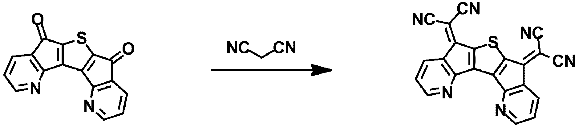
- the compound of Formula 1 may be any one selected from the following compounds.
- the conjugation length of the compound and the energy bandgap are closely related. Specifically, the longer the conjugation length of the compound, the smaller the energy bandgap.
- compounds having various energy band gaps can be synthesized by introducing various substituents into the core structure.
- the HOMO and LUMO energy levels of the compound may be controlled by introducing various substituents into the core structure of the above structure.
- the compound which has the intrinsic property of the introduced substituent can be synthesize
- introducing a substituent mainly used in the hole injection layer material, hole transport material, charge generating material, light emitting layer material and electron transport layer material used in manufacturing the organic light emitting device to the core structure The substance to make can be synthesize
- the organic light emitting device is an organic light emitting device comprising a first electrode, a second electrode, and at least one organic layer disposed between the first electrode and the second electrode, at least one of the organic layer It is characterized by including the compound.
- the organic light emitting device of the present invention may be manufactured by a conventional method and material for manufacturing an organic light emitting device, except that at least one organic material layer is formed using the above-described compound.
- the compound may be formed as an organic material layer by a solution coating method as well as a vacuum deposition method in the manufacture of the organic light emitting device.
- the solution coating method means spin coating, dip coating, inkjet printing, screen printing, spraying method, roll coating and the like, but is not limited thereto.
- the organic material layer of the organic light emitting device of the present invention may have a single layer structure, but may have a multilayer structure in which two or more organic material layers are stacked.
- the organic light emitting device of the present invention may have a structure including a hole injection layer, a hole transport layer, a charge generating layer, a light emitting layer, an electron transport layer, an electron injection layer and the like as an organic material layer.
- the structure of the organic light emitting device is not limited thereto and may include a smaller number of organic material layers.
- the organic material layer may include at least one of a hole injection layer, a hole transport layer, and a layer for simultaneously injecting holes and transporting holes, and at least one of the layers may be represented by Formula 1 above. It may include a compound represented by.
- the organic material layer may include one or more layers of a hole injection layer and a hole transport layer, and one or more of the layers may include a compound represented by Chemical Formula 1.
- the organic material layer may include a hole injection layer, and the hole injection layer may include a compound represented by Chemical Formula 1 as a dopant.
- the organic material layer may include at least one of a hole injection layer, an electron blocking layer, a hole transport layer, and a layer for simultaneously injecting holes and transporting holes, and at least one of the layers may be represented by Formula 1 above. It may include a compound represented by.
- the organic material layer may include an electron blocking layer, and the electron blocking layer may include a compound represented by Chemical Formula 1.
- the organic material layer includes a light emitting layer, and the light emitting layer includes a compound represented by Chemical Formula 1.
- the compound represented by Formula 1 may be included as a host of the light emitting layer.
- the compound represented by Chemical Formula 1 may be included as a phosphorescent host of the emission layer.
- the organic material layer including the compound represented by Chemical Formula 1 may include the compound represented by Chemical Formula 1 as a host, and may include another organic compound, a metal, or a metal compound as a dopant.
- the organic material layer including the compound represented by Chemical Formula 1 may include the compound represented by Chemical Formula 1 as a host, and may be used together with an iridium-based (Ir) dopant.
- the organic material layer may include one or more layers of an electron transport layer, an electron injection layer, and a layer for simultaneously transporting and transporting electrons, and one or more of the layers may include the compound.
- the organic material layer of the organic electronic device includes a hole transport layer, and the hole transport layer includes a compound represented by Chemical Formula 1.
- the organic material layer may include two or more light emitting layers, and may include a charge generation layer including the compound of Formula 1 provided between the two light emitting layers, and the charge generation layer may include the charge generation layer. It may include a compound represented by the formula (1).
- the organic material layer includes the light emitting layer, and the organic material layer includes a compound represented by Chemical Formula 1-A.
- n1 is an integer of 1 or more
- Ar7 is a substituted or unsubstituted monovalent or higher benzofluorene group; Substituted or unsubstituted monovalent or higher fluoranthene group; A substituted or unsubstituted monovalent or higher pyrene group; Or a substituted or unsubstituted monovalent or higher chrysene group,
- L4 is a direct bond; Substituted or unsubstituted arylene group; Or a substituted or unsubstituted heteroarylene group,
- Ar8 and Ar9 are the same as or different from each other, and each independently a substituted or unsubstituted aryl group; Substituted or unsubstituted silyl group; Substituted or unsubstituted germanium group; Substituted or unsubstituted alkyl group; Substituted or unsubstituted arylalkyl group; Or a substituted or unsubstituted heteroaryl group, or may combine with each other to form a substituted or unsubstituted ring,
- n1 is 2 or more
- the structures in two or more parentheses are the same or different from each other.
- the organic material layer includes a light emitting layer, and the organic material layer includes a compound represented by Chemical Formula 1-A as a dopant of the light emitting layer.
- L4 is a direct bond.
- n1 is 2.
- Ar7 is a divalent pyrene group unsubstituted or substituted with deuterium, a methyl group, an ethyl group, or a tert-butyl group.
- Ar8 and Ar9 are the same as or different from each other, and each independently represent a substituted or unsubstituted aryl group having 6 to 30 carbon atoms.
- Ar8 and Ar9 are the same as or different from each other, and each independently an aryl group unsubstituted or substituted with a germanium group substituted with an alkyl group.
- Ar8 and Ar9 are the same or different from each other, and each independently an aryl group unsubstituted or substituted with a trimethylgermanium group.
- Ar8 and Ar9 are the same as or different from each other, and each independently represent a substituted or unsubstituted phenyl group.
- Ar8 and Ar9 is a phenyl group unsubstituted or substituted with a trimethylgernium group.
- Chemical Formula 1-A is represented by the following compound.
- the organic material layer includes a light emitting layer, and the organic material layer includes a compound represented by the following Chemical Formula 2-A.
- Ar4 and Ar5 are the same as or different from each other, and each independently a substituted or unsubstituted monocyclic aryl group; Or a substituted or unsubstituted polycyclic aryl group,
- G1 to G8 are the same as or different from each other, and each independently hydrogen; Substituted or unsubstituted alkyl group; Substituted or unsubstituted monocyclic aryl group; Or a substituted or unsubstituted polycyclic aryl group.
- the organic layer includes a light emitting layer
- the light emitting layer includes a compound represented by Formula 2-A as a host of the light emitting layer.
- Ar4 and Ar5 are the same as or different from each other, and each independently a substituted or unsubstituted polycyclic aryl group.
- Ar4 and Ar5 are the same as or different from each other, and each independently a substituted or unsubstituted naphthyl group.
- Ar4 and Ar5 are the same as or different from each other, and each independently a substituted or unsubstituted 2-naphthyl group.
- Ar4 and Ar5 are 2-naphthyl groups.
- G1 to G8 are the same as or different from each other, and each independently hydrogen; Or a substituted or unsubstituted alkyl group.
- G1 to G8 are the same as or different from each other, and each independently hydrogen; Or a substituted or unsubstituted alkyl group having 1 to 20 carbon atoms.
- G1 to G8 are the same as or different from each other, and each independently hydrogen; Or methyl group.
- Formula 2-A is represented by the following compound.
- the organic material layer includes a light emitting layer
- the light emitting layer includes the compound represented by Chemical Formula 1-A as a dopant of the light emitting layer, and includes the compound represented by Chemical Formula 2-A as a host of the light emitting layer.
- the compound may be included in a light emitting layer, a layer for simultaneously injecting / holes transporting and emitting light, a layer for simultaneously transporting holes and emitting light, or a layer for simultaneously transporting electrons and emitting light.
- the structure of the organic light emitting device of the present invention may have a structure as shown in FIGS. 1, 2 and 3, but is not limited thereto.
- FIG. 1 illustrates a structure of an organic light emitting device in which an anode 2, a light emitting layer 3, and a cathode 4 are sequentially stacked on a substrate 1.
- the compound may be included in the light emitting layer (3).
- FIG. 2 illustrates an organic light emitting device in which an anode 2, a hole injection layer 5, a hole transport layer 6, a light emitting layer 3, an electron transport layer 7, and a cathode 4 are sequentially stacked on a substrate 1.
- the structure is illustrated.
- the compound may be included in the hole injection layer 5, the hole transport layer 6, the light emitting layer 3, or the electron transport layer 7.
- an organic light emitting device including two units including electron transport layers 8a and 8b, wherein a charge generation layer 9 is provided between the units.
- the organic light emitting device uses a metal vapor deposition (PVD) method such as sputtering or e-beam evaporation, and has a metal oxide or a metal oxide or an alloy thereof on a substrate. It can be prepared by depositing an anode to form an anode, an organic material layer including a hole injection layer, a hole transport layer, a light emitting layer and an electron transport layer thereon, and then depositing a material that can be used as a cathode thereon.
- PVD metal vapor deposition
- an organic light emitting device may be manufactured by sequentially depositing a cathode material, an organic material layer, and an anode material on a substrate.
- the organic material layer may have a multilayer structure including a hole injection layer, a hole transport layer, a light emitting layer, and an electron transport layer, but is not limited thereto and may have a single layer structure.
- the organic layer may be prepared by using a variety of polymer materials, and by using a method such as spin coating, dip coating, doctor blading, screen printing, inkjet printing, or thermal transfer, rather than a deposition method. It can be prepared in layers.
- the anode material a material having a large work function is usually preferred to facilitate hole injection into the organic material layer.
- the positive electrode material that can be used in the present invention include metals such as vanadium, chromium, copper, zinc and gold or alloys thereof; Metal oxides such as zinc oxide, indium oxide, indium tin oxide (ITO), indium zinc oxide (IZO); A combination of a metal and an oxide such as ZnO: Al or SnO 2 : Sb; Conductive polymers such as poly (3-methyl compound), poly [3,4- (ethylene-1,2-dioxy) compound] (PEDT), polypyrrole and polyaniline, and the like, but are not limited thereto.
- the cathode material is a material having a small work function to facilitate electron injection into the organic material layer.
- the negative electrode material include metals such as magnesium, calcium, sodium, potassium, titanium, indium, yttrium, lithium, gadolinium, aluminum, silver, tin, and lead or alloys thereof; Multilayer structure materials such as LiF / Al or LiO 2 / Al, and the like, but are not limited thereto.
- the hole injection material is a material capable of well injecting holes from the anode at a low voltage, and the highest occupied molecular orbital (HOMO) of the hole injection material is preferably between the work function of the anode material and the HOMO of the surrounding organic material layer.
- the hole injection material include metal porphyrine, oligothiophene, arylamine-based organics, hexanitrile hexaazatriphenylene-based organics, quinacridone-based organics, and perylene-based Organic compounds, anthraquinones and polyaniline and poly-compounds of conductive polymers, and the like, but are not limited thereto.
- the hole transporting material a material capable of transporting holes from the anode or the hole injection layer to be transferred to the light emitting layer is suitable.
- a material capable of transporting holes from the anode or the hole injection layer to be transferred to the light emitting layer is suitable.
- Specific examples thereof include an arylamine-based organic material, a conductive polymer, and a block copolymer having a conjugated portion and a non-conjugated portion together, but are not limited thereto.
- the light emitting material is a material capable of emitting light in the visible region by transporting and combining holes and electrons from the hole transport layer and the electron transport layer, respectively, and a material having good quantum efficiency with respect to fluorescence or phosphorescence is preferable.
- Specific examples thereof include 8-hydroxyquinoline aluminum complex (Alq 3 ); Carbazole series compounds; Dimerized styryl compounds; BAlq; 10-hydroxybenzoquinoline-metal compound; Benzoxazole, benzthiazole and benzimidazole series compounds; Poly (p-phenylenevinylene) (PPV) -based polymers; Spiro compounds; Polyfluorene, rubrene and the like, but are not limited thereto.
- Iridium complex used as a dopant of a light emitting layer is as follows.
- the electron transporting material is a material capable of injecting electrons well from the cathode and transferring the electrons to the light emitting layer.
- a material having high mobility to electrons is suitable. Specific examples include Al complexes of 8-hydroxyquinoline; Complexes including Alq 3 ; Organic radical compounds; Hydroxyflavone-metal complexes and the like, but are not limited thereto.
- the organic light emitting device according to the present invention may be a top emission type, a bottom emission type or a double-sided emission type depending on the material used.
- the compound according to the present invention may also operate on a principle similar to that applied to organic light emitting devices in organic electronic devices including organic solar cells, organic photoconductors, organic transistors, and the like.
- the light emitting area of the ITO glass was patterned to have a size of 3 mm ⁇ 3 mm and then washed.
- the substrate was mounted in a vacuum chamber, and the base pressure was 1 ⁇ 10 ⁇ 6 torr.
- Compound 37 was formed to a thickness of 100 kPa using a hole injection layer on the anode ITO.
- ⁇ -NPD was formed to a thickness of 600 GPa with the hole transport layer
- BD-A as a dopant was deposited on the host MADN with a weight ratio of 40: 2 as the light emitting layer
- Alq 3 was formed at a thickness of 300 GPa with the electron transport layer.
- LiF was formed to a thickness of 10 GPa as an electron injection layer, and Al was sequentially formed to a thickness of 800 GPa as a cathode to fabricate an organic light emitting device.
- the luminance was measured using Minolta CS1000 and the luminous efficiency at 10 mA / cm 2 was calculated.
- the organic light emitting device was manufactured by using only the compound 13 instead of the compound 37 in the hole injection layer.
- the organic light emitting device was manufactured by using only the compound 39 instead of the compound 37 in the hole injection layer.
- the organic light emitting device was manufactured by using only the compound 1 instead of the compound 37 in the hole injection layer.
- the organic light emitting device was manufactured by using only the compound 3 instead of the compound 37 in the hole injection layer.
- the organic light emitting device was manufactured by using only the compound 78 instead of the compound 37 in the hole injection layer.
- the organic light emitting device was manufactured by using only the compound 81 instead of the compound 37 in the hole injection layer.
- the organic light emitting device was manufactured by using only the compound 65 instead of the compound 37 in the hole injection layer.
- an organic light emitting device was manufactured by using only HAT-CN instead of Compound 37 in the hole injection layer.
- the organic light emitting device was manufactured by using only ⁇ -NPD instead of compound 37 in the hole injection layer.
- an organic light emitting device was manufactured by using only the following compound instead of compound 37 in the hole injection layer.
- the driving voltage was reduced by about 16 to 31% compared to Comparative Example 1, and the driving voltage was reduced by 39 to 50% compared to Comparative Example 2.
- the experimental example of the present invention has improved current efficiency, power efficiency and brightness compared to the comparative example.
- the present specification provides an embodiment in which an organic light emitting device is manufactured by doping a compound according to the present invention to a hole injection layer.
- the light emitting area of the ITO glass was patterned to have a size of 3 mm ⁇ 3 mm and then washed.
- the basic pressure was 1x10 -6 torr
- ⁇ -NPD was formed to a thickness of 100 ⁇ s with a hole injection layer on the anode ITO, but the compound 37 was doped with a doping concentration of 25%.
- ⁇ -NPD was formed to a thickness of 600 ⁇ as the hole transport layer
- BD-A as a dopant was deposited to the weight ratio of 40: 2 in the host MADN as the light emitting layer
- Alq 3 was formed to have a thickness of 300 ⁇ as the electron transport layer.
- LiF was formed to a thickness of 10 mW as a layer, and Al was sequentially formed to a thickness of 800 mW as a cathode to fabricate an organic light emitting device.
- the luminance was measured using Minolta CS1000 and the luminous efficiency at 10 mA / cm 2 was calculated.
- the organic light emitting device was manufactured by changing only the doping concentration of Compound 1 into the hole injection layer instead of Compound 37 at 25% doping concentration.
- the organic light emitting device was manufactured by using only the compound 13 instead of the compound 37 at a doping concentration of 25% in the hole injection layer.
- the organic light emitting device was manufactured by using only the compound 39 instead of the compound 37 at a doping concentration of 25% in the hole injection layer.
- the organic light emitting device was manufactured by using only the compound 65 instead of the compound 37 at a doping concentration of 25% in the hole injection layer.
- the organic light emitting device was manufactured by changing only the doping concentration of HAT-CN in the hole injection layer instead of the compound 37 at 25% doping concentration.
- the organic light emitting device was manufactured by using only ⁇ -NPD without doping in the hole injection layer.
- the organic light emitting device was manufactured by changing only the following compound, instead of compound 37, in the hole injection layer at a doping concentration of 25%.
- Experimental Examples 9 to 13 of the present invention reduced the drive voltage by 19 to 28% compared to Comparative Example 4, 41 to 47% reduced the drive voltage compared to Comparative Example 5.
- the experimental example of the present invention has improved current efficiency, power efficiency and brightness compared to the comparative example.
Landscapes
- Chemical & Material Sciences (AREA)
- Organic Chemistry (AREA)
- Engineering & Computer Science (AREA)
- Materials Engineering (AREA)
- Physics & Mathematics (AREA)
- Spectroscopy & Molecular Physics (AREA)
- Optics & Photonics (AREA)
- Electroluminescent Light Sources (AREA)
- Plural Heterocyclic Compounds (AREA)
- Heterocyclic Carbon Compounds Containing A Hetero Ring Having Oxygen Or Sulfur (AREA)
Abstract
Description


| 구동 전압(V) | 전류밀도(mA/cm2) | 전류효율(cd/A) | 전력효율(lm/W) | 휘도(cd/m2) | |
| 실험예 1(화합물 37) | 4.2 | 10 | 5.86 | 4.383 | 586 |
| 실험예 2(화합물 13) | 4.0 | 10 | 6.02 | 4.728 | 602 |
| 실험예 3(화합물 39) | 4.0 | 10 | 5.96 | 4.681 | 596 |
| 실험예 4(화합물 1) | 4.5 | 10 | 5.62 | 3.924 | 562 |
| 실험예 5(화합물 3) | 4.3 | 10 | 5.52 | 4.033 | 552 |
| 실험예 6(화합물 78) | 4.8 | 10 | 5.34 | 3.495 | 534 |
| 실험예 7(화합물 81) | 4.9 | 10 | 5.18 | 3.321 | 518 |
| 실험예 8(화합물 65) | 4.7 | 10 | 5.42 | 3.623 | 542 |
| 비교예 1 | 5.8 | 10 | 4.52 | 2.448 | 452 |
| 비교예 2 | 8.0 | 10 | 4.12 | 1.618 | 412 |
| 비교예 3 | 6.0 | 10 | 4.48 | 2.346 | 448 |


| 구동전압(V) | 전류밀도(mA/cm2) | 전류효율(cd/A) | 전력효율(lm/W) | 휘도(cd/m2) | |
| 실험예 9(화합물 37) | 4.4 | 10 | 5.56 | 3.970 | 556 |
| 실험예 10(화합물 1) | 4.6 | 10 | 5.5 | 3.756 | 550 |
| 실험예 11(화합물 13) | 4.2 | 10 | 5.86 | 4.383 | 586 |
| 실험예 12(화합물 39) | 4.2 | 10 | 5.59 | 4.181 | 559 |
| 실험예 13(화합물 65) | 4.7 | 10 | 5.4 | 3.609 | 540 |
| 비교예4 | 5.8 | 10 | 4.5 | 2.437 | 450 |
| 비교예5 | 8.0 | 10 | 4.12 | 1.618 | 412 |
| 비교예6 | 6.0 | 10 | 4.39 | 2.299 | 439 |
Claims (17)
- 하기 화학식 1로 표시되는 화합물:[화학식 1]
 상기 화학식 1에 있어서,Z는 치환 또는 비치환된 티오펜 고리; 또는 치환 또는 비치환된 티에노티오펜 고리이고,Ar1은이며,
 Ar2는이고,
 X1 및 X2는 서로 같거나 상이하고, 각각 독립적으로 하기 (a) 내지 (g) 중에서 선택된 어느 하나이며,
 Y1 내지 Y4는 서로 같거나 상이하고, 각각 독립적으로 N; CH; 또는 CR5이며,R1 내지 R5는 서로 같거나 상이하고, 각각 독립적으로 수소; 중수소; 할로겐기; 니트릴기; 치환 또는 비치환된 알킬기; 치환 또는 비치환된 할로알킬기; 치환 또는 비치환된 알콕시기; 치환 또는 비치환된 할로알콕시기; 치환 또는 비치환된 아릴기; 치환 또는 비치환된 할로아릴기; 치환 또는 비치환된 실릴기; 또는 치환 또는 비치환된 헤테로 고리기이거나, R1 내지 R5 중 인접한 기가 서로 결합하여 치환 또는 비치환된 방향족 탄화수소 고리 또는 치환 또는 비치환된 헤테로 고리를 형성하고,Z가 치환 또는 비치환된 티오펜 고리고 Y1 내지 Y4가 모두 CH이며 X1 및 X2는 서로 같거나 상이하고 각각 (a) 내지 (f) 중 어느 하나인 경우에는 R1 내지 R5 중 적어도 하나가 중수소; 할로겐기; 니트릴기; 치환 또는 비치환된 알킬기; 치환 또는 비치환된 할로알킬기; 치환 또는 비치환된 알콕시기; 치환 또는 비치환된 할로알콕시기; 치환 또는 비치환된 아릴기; 치환 또는 비치환된 할로아릴기; 치환 또는 비치환된 실릴기; 또는 치환 또는 비치환된 헤테로 고리기이거나, R1 내지 R5 중 인접한 기가 서로 결합하여 치환 또는 비치환된 방향족 탄화수소 고리 또는 치환 또는 비치환된 헤테로 고리를 형성하며,R21 내지 R24는 서로 같거나 상이하고, 각각 독립적으로 수소; 중수소; 치환 또는 비치환된 알킬기; 치환 또는 비치환된 시클로알킬기; 치환 또는 비치환된 아릴기; 또는 치환 또는 비치환된 헤테로 고리기이다.
 - 청구항 1에 있어서, 상기 화학식 1의 화합물은 하기 화학식 2 내지 화학식 4 중 어느 하나로 표시되는 것인 화합물:[화학식 2]
 [화학식 3]
 [화학식 4]
 상기 화학식 2 내지 화학식 4에서,X1, X2, Y1 내지 Y4, R1 내지 R5 및 R21 내지 R24의 정의는 화학식 1에서와 같다.
 - 청구항 1에 있어서, 상기 화학식 1의 화합물은 하기 화학식 5 내지 화학식 8 중 어느 하나로 표시되는 것인 화합물:[화학식 5]
 [화학식 6]
 [화학식 7]
 [화학식 8]
 상기 화학식 5 내지 화학식 8에서,X1, X2, Y1 내지 Y4, R1 내지 R5 및 R21 내지 R24의 정의는 화학식 1에서와 같다.
 - 청구항 1에 있어서, 상기 화학식 1의 화합물은 하기 화학식 9 내지 화학식 11 중 어느 하나로 표시되는 것인 화합물:[화학식 9]
 [화학식 10]
 [화학식 11]
 상기 화학식 9 내지 화학식 11에서,X1, X2, Y1 내지 Y4, R1 내지 R5 및 R21 내지 R24의 정의는 화학식 1에서와 같다.
 - 청구항 1에 있어서, 상기 화학식 1의 화합물은 하기 화합물에서 선택되는 어느 하나인 것인 화합물:


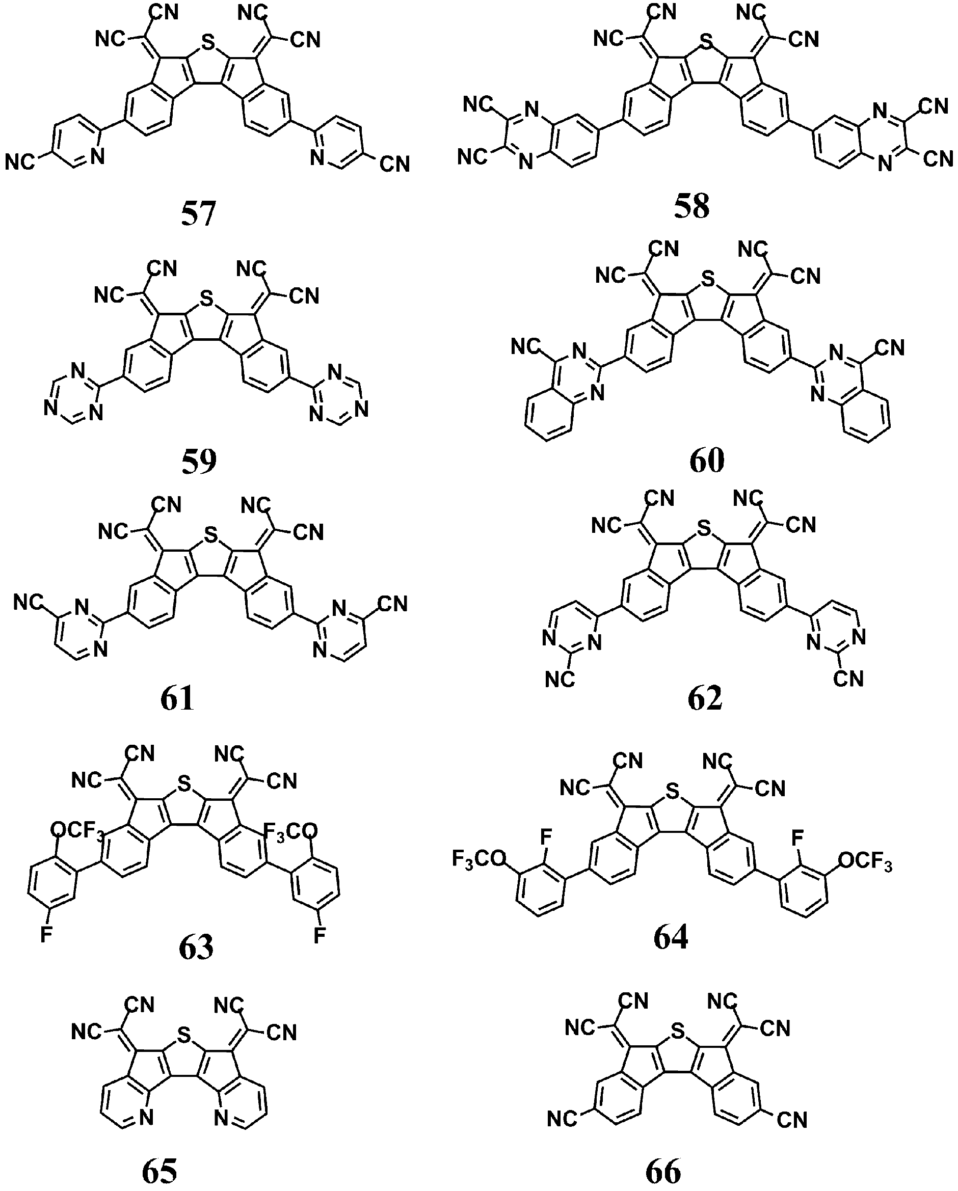


 .
.
- 제1 전극, 제2 전극, 및 상기 제1 전극과 제2 전극 사이에 배치된 1층 이상의 유기물층을 포함하는 유기 발광 소자로서, 상기 유기물층 중 1층 이상은 청구항 1 내지 5 중 어느 하나의 항에 따른 화합물을 포함하는 것을 특징으로 하는 유기 발광 소자.
- 청구항 6에 있어서 전자 수송층, 전자 주입층, 및 전자 수송 및 전자 주입을 동시에 하는 층 중 1층 이상을 포함하고, 상기 층들 중 1층 이상이 상기 화합물을 포함하는 것을 특징으로 하는 유기 발광 소자.
- 청구항 6에 있어서, 상기 유기물층은 발광층을 포함하고, 상기 발광층이 상기 화합물을 발광층의 호스트로서 포함하는 것인 유기 발광 소자.
- 청구항 6에 있어서, 상기 유기물층은 정공 주입층, 전자 저지층, 정공 수송층, 및 정공 주입 및 정공 수송을 동시에 하는 층 중 1층 이상의 층을 포함하고, 상기 층들 중 1층 이상이 상기 화합물을 포함하는 것을 특징으로 하는 유기 발광 소자.
- 청구항 6에 있어서, 상기 유기물층은 정공 주입층을 포함하고, 상기 정공 주입층이 상기 화학식 1로 표시되는 화합물을 도펀트로서 포함하는 것인 유기 발광 소자.
- 청구항 6에 있어서, 상기 유기물층은 상기 화합물을 호스트로서 포함하고, 다른 유기 화합물, 금속 또는 금속 화합물을 도펀트로 포함하는 것인 유기 발광 소자.
- 청구항 6에 있어서, 상기 유기물층은 2층 이상의 발광층을 포함하고, 상기 2층의 발광층 사이에 구비된 전하생성층(charge generation layer)을 포함하며, 상기 전하생성층이 상기 화합물을 포함하는 것을 특징으로 하는 유기 발광 소자.
- 청구항 6에 있어서, 상기 유기물층은 하기 화학식 1-A로 표시되는 화합물을 포함하는 것인 유기 발광 소자:[화학식 1-A]
 상기 화학식 1-A에 있어서,n1은 1 이상의 정수이고,Ar7은 치환 또는 비치환된 1가 이상의 벤조플루오렌기; 치환 또는 비치환된 1가 이상의 플루오란텐기; 치환 또는 비치환된 1가 이상의 파이렌기; 또는 치환 또는 비치환된 1가 이상의 크라이센기이고,L4은 직접결합; 치환 또는 비치환된 아릴렌기; 또는 치환 또는 비치환된 헤테로아릴렌기이며,Ar8 및 Ar9는 서로 같거나 상이하고, 각각 독립적으로 치환 또는 비치환된 아릴기; 치환 또는 비치환된 실릴기; 치환 또는 비치환된 게르마늄기; 치환 또는 비치환된 알킬기; 치환 또는 비치환된 아릴알킬기; 또는 치환 또는 비치환된 헤테로아릴기이거나, 서로 결합하여 치환 또는 비치환된 고리를 형성할 수 있으며,n1이 2 이상인 경우, 2 이상의 괄호 안의 구조는 서로 같거나 상이하다.
 - 청구항 13에 있어서, 상기 L4은 직접결합이고, Ar7는 2 가의 파이렌기이며, Ar8 및 Ar9는 서로 같거나 상이하고, 각각 독립적으로 탄소수 1 내지 30의 알킬기로 치환 또는 비치환된 탄소수 6 내지 30의 아릴기, 또는 치환 또는 비치환된 탄소수 2 내지 30의 헤테로아릴기이고, n1은 2인 것인 유기 발광 소자.
- 청구항 6에 있어서, 상기 유기물층은 하기 화학식 2-A로 표시되는 화합물을 포함하는 것인 유기 발광 소자:[화학식 2-A]
 상기 화학식 2-A에 있어서,Ar4 및 Ar5는 서로 같거나 상이하고, 각각 독립적으로 치환 또는 비치환된 단환의 아릴기; 또는 치환 또는 비치환된 다환의 아릴기이고,G1 내지 G8은 서로 같거나 상이하고, 각각 독립적으로 수소; 치환 또는 비치환된 알킬기; 치환 또는 비치환된 단환의 아릴기; 또는 치환 또는 비치환된 다환의 아릴기이다.
 - 청구항 15에 있어서, 상기 Ar4 및 Ar5는 2-나프틸기이고, G1 내지 G8은 수소 또는 치환 또는 비치환된 알킬기인 것인 유기 전자 소자.
- 청구항 13에 있어서, 상기 유기물층은 하기 화학식 2-A로 표시되는 화합물을 포함하는 것인 유기 발광 소자:[화학식 2-A]
 상기 화학식 2-A에 있어서,Ar4 및 Ar5는 서로 같거나 상이하고, 각각 독립적으로 치환 또는 비치환된 단환의 아릴기; 또는 치환 또는 비치환된 다환의 아릴기이고,G1 내지 G8은 서로 같거나 상이하고, 각각 독립적으로 수소; 치환 또는 비치환된 알킬기; 치환 또는 비치환된 단환의 아릴기; 또는 치환 또는 비치환된 다환의 아릴기이다.
Priority Applications (4)
| Application Number | Priority Date | Filing Date | Title |
|---|---|---|---|
| JP2017508084A JP6624196B2 (ja) | 2015-10-26 | 2016-10-26 | 複素環化合物及びこれを含む有機発光素子{heterocyclic compound and organic light emitting device comprising the same} |
| US15/562,581 US10519166B2 (en) | 2015-10-26 | 2016-10-26 | Heterocyclic compound and organic light emitting device comprising the same |
| CN201680020857.7A CN107922376B (zh) | 2015-10-26 | 2016-10-26 | 杂环化合物及包含其的有机发光器件 |
| EP16860201.9A EP3369731B1 (en) | 2015-10-26 | 2016-10-26 | Heterocyclic compound and organic light emitting element comprising same |
Applications Claiming Priority (2)
| Application Number | Priority Date | Filing Date | Title |
|---|---|---|---|
| KR10-2015-0148680 | 2015-10-26 | ||
| KR20150148680 | 2015-10-26 |
Publications (2)
| Publication Number | Publication Date |
|---|---|
| WO2017074018A2 true WO2017074018A2 (ko) | 2017-05-04 |
| WO2017074018A3 WO2017074018A3 (ko) | 2017-10-12 |
Family
ID=58631719
Family Applications (1)
| Application Number | Title | Priority Date | Filing Date |
|---|---|---|---|
| PCT/KR2016/012078 Ceased WO2017074018A2 (ko) | 2015-10-26 | 2016-10-26 | 헤테로환 화합물 및 이를 포함하는 유기 발광 소자 |
Country Status (7)
| Country | Link |
|---|---|
| US (1) | US10519166B2 (ko) |
| EP (1) | EP3369731B1 (ko) |
| JP (1) | JP6624196B2 (ko) |
| KR (1) | KR101962333B1 (ko) |
| CN (2) | CN107922376B (ko) |
| TW (1) | TWI642661B (ko) |
| WO (1) | WO2017074018A2 (ko) |
Families Citing this family (9)
| Publication number | Priority date | Publication date | Assignee | Title |
|---|---|---|---|---|
| CN111333647B (zh) * | 2018-12-19 | 2021-03-12 | 广东阿格蕾雅光电材料有限公司 | 有机电致发光材料及其应用 |
| CN111454276B (zh) | 2019-01-18 | 2022-01-11 | 北京夏禾科技有限公司 | 一种有机化合物及包含其的电致发光器件 |
| CN111909213B (zh) * | 2019-05-09 | 2024-02-27 | 北京夏禾科技有限公司 | 一种含有三个不同配体的金属配合物 |
| CN112679548B (zh) | 2019-10-18 | 2023-07-28 | 北京夏禾科技有限公司 | 具有部分氟取代的取代基的辅助配体的有机发光材料 |
| CN118084980A (zh) | 2020-01-10 | 2024-05-28 | 北京夏禾科技有限公司 | 有机发光材料 |
| CN113121609B (zh) | 2020-01-16 | 2024-03-29 | 北京夏禾科技有限公司 | 一种金属配合物、包含其的电致发光器件及其用途 |
| KR20220090667A (ko) * | 2020-12-22 | 2022-06-30 | 삼성디스플레이 주식회사 | 발광 소자 및 이를 포함한 전자 장치 |
| CN113054124A (zh) * | 2021-02-20 | 2021-06-29 | 京东方科技集团股份有限公司 | 一种有机发光器件、显示装置、制作方法以及存储介质 |
| KR20250128345A (ko) | 2022-12-23 | 2025-08-27 | 메르크 파텐트 게엠베하 | 전자 디바이스 |
Citations (1)
| Publication number | Priority date | Publication date | Assignee | Title |
|---|---|---|---|---|
| KR20130007441A (ko) | 2011-06-27 | 2013-01-18 | 주식회사 엘지화학 | 새로운 화합물 및 이를 이용한 유기 발광 소자 |
Family Cites Families (13)
| Publication number | Priority date | Publication date | Assignee | Title |
|---|---|---|---|---|
| JP5484472B2 (ja) * | 2008-09-23 | 2014-05-07 | エルジー・ケム・リミテッド | 新規な化合物、その製造方法、およびそれを用いた有機電子素子 |
| JP2010280623A (ja) * | 2009-06-05 | 2010-12-16 | Chisso Corp | 平面性の高い分子構造を有する化合物およびこれを用いた有機トランジスタ |
| US9288074B2 (en) | 2011-06-30 | 2016-03-15 | International Business Machines Corporation | Resource configuration change management |
| WO2013036043A2 (ko) * | 2011-09-09 | 2013-03-14 | 주식회사 엘지화학 | 유기 발광 소자 재료 및 이를 이용한 유기 발광 소자 |
| JP2015501303A (ja) * | 2011-10-20 | 2015-01-15 | メルク パテント ゲゼルシャフト ミット ベシュレンクテル ハフツングMerck Patent Gesellschaft mit beschraenkter Haftung | 有機半導体 |
| KR20140135749A (ko) * | 2012-02-16 | 2014-11-26 | 메르크 파텐트 게엠베하 | 유기 반도체성 중합체 |
| TWI438220B (zh) * | 2012-03-08 | 2014-05-21 | Univ Nat Chiao Tung | 化合物及其合成方法 |
| EP2867271A1 (en) * | 2012-07-02 | 2015-05-06 | Merck Patent GmbH | Conjugated polymers |
| CN104203941B (zh) * | 2012-07-13 | 2017-03-01 | 株式会社Lg化学 | 杂环化合物及包含其的有机电子装置 |
| EP2888307B1 (en) * | 2012-08-24 | 2017-09-06 | Merck Patent GmbH | Conjugated polymers |
| KR101560061B1 (ko) * | 2012-11-30 | 2015-10-15 | 주식회사 엘지화학 | 신규한 화합물 및 이를 이용한 유기 전자 소자 |
| KR20150010016A (ko) * | 2013-07-17 | 2015-01-28 | 롬엔드하스전자재료코리아유한회사 | 유기 전계 발광 소자 |
| US9876182B2 (en) * | 2013-07-26 | 2018-01-23 | University Of Oregon | Thieno-containing compounds and processes and uses thereof |
-
2016
- 2016-10-26 TW TW105134534A patent/TWI642661B/zh active
- 2016-10-26 EP EP16860201.9A patent/EP3369731B1/en active Active
- 2016-10-26 KR KR1020160140138A patent/KR101962333B1/ko active Active
- 2016-10-26 US US15/562,581 patent/US10519166B2/en active Active
- 2016-10-26 WO PCT/KR2016/012078 patent/WO2017074018A2/ko not_active Ceased
- 2016-10-26 JP JP2017508084A patent/JP6624196B2/ja active Active
- 2016-10-26 CN CN201680020857.7A patent/CN107922376B/zh active Active
- 2016-10-26 CN CN201910129316.3A patent/CN109956924B9/zh active Active
Patent Citations (1)
| Publication number | Priority date | Publication date | Assignee | Title |
|---|---|---|---|---|
| KR20130007441A (ko) | 2011-06-27 | 2013-01-18 | 주식회사 엘지화학 | 새로운 화합물 및 이를 이용한 유기 발광 소자 |
Non-Patent Citations (4)
| Title |
|---|
| CHEMICAL SCIENCE, vol. 5, 2014, pages 4490 |
| MACROMOLECULES, vol. 38, 2005, pages 19 |
| See also references of EP3369731A4 |
| TETRAHEDRON, vol. 65, 2009, pages 6141 |
Also Published As
| Publication number | Publication date |
|---|---|
| KR20170048221A (ko) | 2017-05-08 |
| EP3369731A2 (en) | 2018-09-05 |
| EP3369731B1 (en) | 2020-02-19 |
| KR101962333B1 (ko) | 2019-07-17 |
| JP2018519240A (ja) | 2018-07-19 |
| EP3369731A4 (en) | 2019-05-08 |
| US20180086775A1 (en) | 2018-03-29 |
| CN109956924A (zh) | 2019-07-02 |
| CN107922376B (zh) | 2019-05-14 |
| CN107922376A (zh) | 2018-04-17 |
| WO2017074018A3 (ko) | 2017-10-12 |
| US10519166B2 (en) | 2019-12-31 |
| JP6624196B2 (ja) | 2019-12-25 |
| CN109956924B (zh) | 2021-08-20 |
| TW201728576A (zh) | 2017-08-16 |
| TWI642661B (zh) | 2018-12-01 |
| CN109956924B9 (zh) | 2021-10-01 |
Similar Documents
| Publication | Publication Date | Title |
|---|---|---|
| WO2019168368A1 (ko) | 유기 발광 소자 | |
| WO2014010824A1 (ko) | 헤테로환 화합물 및 이를 포함하는 유기 전자 소자 | |
| WO2016182388A2 (ko) | 헤테로고리 화합물 및 이를 포함하는 유기 발광 소자 | |
| WO2017074018A2 (ko) | 헤테로환 화합물 및 이를 포함하는 유기 발광 소자 | |
| WO2019190223A1 (ko) | 화합물 및 이를 포함하는 유기 발광 소자 | |
| WO2017047977A1 (ko) | 헤테로환 화합물 및 이를 포함하는 유기 발광 소자 | |
| WO2015046988A1 (ko) | 헤테로환 화합물 및 이를 이용한 유기 발광 소자 | |
| WO2015046835A1 (ko) | 헤테로환 화합물 및 이를 포함하는 유기 발광 소자 | |
| WO2020022860A1 (ko) | 신규한 화합물 및 이를 이용한 유기발광 소자 | |
| WO2017052138A2 (ko) | 아민계 화합물 및 이를 포함하는 유기 발광 소자 | |
| WO2017086713A1 (ko) | 화합물 및 이를 포함하는 유기전자소자 | |
| WO2018182297A1 (ko) | 벤조카바졸계 화합물 및 이를 포함하는 유기 발광 소자 | |
| WO2017160068A1 (ko) | 헤테로고리 화합물 및 이를 포함하는 유기 발광 소자 | |
| WO2023018267A1 (ko) | 신규한 화합물 및 이를 이용한 유기 발광 소자 | |
| WO2016140551A2 (ko) | 헤테로고리 화합물 및 이를 포함하는 유기 발광 소자 | |
| WO2018056773A1 (ko) | 아민계 화합물 및 이를 포함하는 유기 발광 소자 | |
| WO2016137068A1 (ko) | 헤테로고리 화합물 및 이를 포함하는 유기 발광 소자 | |
| WO2024210445A1 (ko) | 화합물 및 이를 포함하는 유기 발광 소자 | |
| WO2017073931A1 (ko) | 스피로형 화합물 및 이를 포함하는 유기 발광 소자 | |
| WO2021125813A1 (ko) | 화합물 및 이를 포함하는 유기 발광 소자 | |
| WO2021091165A1 (ko) | 유기 발광 소자 | |
| WO2023200315A1 (ko) | 신규한 화합물 및 이를 이용한 유기 발광 소자 | |
| WO2023121096A1 (ko) | 신규한 화합물 및 이를 이용한 유기 발광 소자 | |
| WO2017052221A1 (ko) | 신규 화합물 및 이를 포함하는 유기 발광 소자 | |
| WO2017061810A1 (ko) | 이중 스피로형 화합물 및 이를 포함하는 유기 발광 소자 |
Legal Events
| Date | Code | Title | Description |
|---|---|---|---|
| ENP | Entry into the national phase |
Ref document number: 2017508084 Country of ref document: JP Kind code of ref document: A |
|
| 121 | Ep: the epo has been informed by wipo that ep was designated in this application |
Ref document number: 16860201 Country of ref document: EP Kind code of ref document: A2 |
|
| WWE | Wipo information: entry into national phase |
Ref document number: 15562581 Country of ref document: US |
|
| REEP | Request for entry into the european phase |
Ref document number: 2016860201 Country of ref document: EP |
|
| NENP | Non-entry into the national phase |
Ref country code: DE |