WO2017076250A1 - 无线通信设备和无线通信方法 - Google Patents
无线通信设备和无线通信方法 Download PDFInfo
- Publication number
- WO2017076250A1 WO2017076250A1 PCT/CN2016/103994 CN2016103994W WO2017076250A1 WO 2017076250 A1 WO2017076250 A1 WO 2017076250A1 CN 2016103994 W CN2016103994 W CN 2016103994W WO 2017076250 A1 WO2017076250 A1 WO 2017076250A1
- Authority
- WO
- WIPO (PCT)
- Prior art keywords
- csi
- wireless communication
- user equipment
- communication device
- base station
- Prior art date
- Legal status (The legal status is an assumption and is not a legal conclusion. Google has not performed a legal analysis and makes no representation as to the accuracy of the status listed.)
- Ceased
Links
Images


Classifications
-
- H—ELECTRICITY
- H04—ELECTRIC COMMUNICATION TECHNIQUE
- H04B—TRANSMISSION
- H04B7/00—Radio transmission systems, i.e. using radiation field
- H04B7/02—Diversity systems; Multi-antenna system, i.e. transmission or reception using multiple antennas
- H04B7/04—Diversity systems; Multi-antenna system, i.e. transmission or reception using multiple antennas using two or more spaced independent antennas
- H04B7/06—Diversity systems; Multi-antenna system, i.e. transmission or reception using multiple antennas using two or more spaced independent antennas at the transmitting station
- H04B7/0613—Diversity systems; Multi-antenna system, i.e. transmission or reception using multiple antennas using two or more spaced independent antennas at the transmitting station using simultaneous transmission
- H04B7/0615—Diversity systems; Multi-antenna system, i.e. transmission or reception using multiple antennas using two or more spaced independent antennas at the transmitting station using simultaneous transmission of weighted versions of same signal
- H04B7/0619—Diversity systems; Multi-antenna system, i.e. transmission or reception using multiple antennas using two or more spaced independent antennas at the transmitting station using simultaneous transmission of weighted versions of same signal using feedback from receiving side
- H04B7/0621—Feedback content
- H04B7/0626—Channel coefficients, e.g. channel state information [CSI]
-
- H—ELECTRICITY
- H04—ELECTRIC COMMUNICATION TECHNIQUE
- H04W—WIRELESS COMMUNICATION NETWORKS
- H04W24/00—Supervisory, monitoring or testing arrangements
- H04W24/02—Arrangements for optimising operational condition
-
- H—ELECTRICITY
- H04—ELECTRIC COMMUNICATION TECHNIQUE
- H04L—TRANSMISSION OF DIGITAL INFORMATION, e.g. TELEGRAPHIC COMMUNICATION
- H04L5/00—Arrangements affording multiple use of the transmission path
- H04L5/003—Arrangements for allocating sub-channels of the transmission path
- H04L5/0048—Allocation of pilot signals, i.e. of signals known to the receiver
-
- H—ELECTRICITY
- H04—ELECTRIC COMMUNICATION TECHNIQUE
- H04W—WIRELESS COMMUNICATION NETWORKS
- H04W16/00—Network planning, e.g. coverage or traffic planning tools; Network deployment, e.g. resource partitioning or cells structures
- H04W16/24—Cell structures
- H04W16/28—Cell structures using beam steering
-
- H—ELECTRICITY
- H04—ELECTRIC COMMUNICATION TECHNIQUE
- H04W—WIRELESS COMMUNICATION NETWORKS
- H04W24/00—Supervisory, monitoring or testing arrangements
- H04W24/10—Scheduling measurement reports ; Arrangements for measurement reports
-
- H—ELECTRICITY
- H04—ELECTRIC COMMUNICATION TECHNIQUE
- H04W—WIRELESS COMMUNICATION NETWORKS
- H04W72/00—Local resource management
- H04W72/50—Allocation or scheduling criteria for wireless resources
- H04W72/54—Allocation or scheduling criteria for wireless resources based on quality criteria
- H04W72/542—Allocation or scheduling criteria for wireless resources based on quality criteria using measured or perceived quality
-
- H—ELECTRICITY
- H04—ELECTRIC COMMUNICATION TECHNIQUE
- H04W—WIRELESS COMMUNICATION NETWORKS
- H04W88/00—Devices specially adapted for wireless communication networks, e.g. terminals, base stations or access point devices
- H04W88/02—Terminal devices
Definitions
- the present disclosure generally relates to the field of wireless communications, and more particularly to a wireless communication device and a wireless communication method for a base station side and a user equipment side.
- a channel information reference signal is defined in Long Term Evolution (LTE) R10, and information that the UE needs to feed back, such as a precoding matrix index (PMI) and a channel quality indicator (CQI), can be calculated by measuring the CSI-RS. ) and rank indication (RI).
- PMI precoding matrix index
- CQI channel quality indicator
- RI rank indication
- CSI-RS mechanisms such as a beamformed CSI-RS mechanism and a non-precoded CSI-RS mechanism.
- a wireless communication device for a base station side includes one or more processors.
- the processor is configured to obtain a distribution of the user equipment and determine a channel state information reference signal CSI-RS mechanism to employ based on the distribution of the user equipment.
- the processor is further configured to generate indication information for indicating to the user equipment the CSI-RS mechanism to be employed.
- the processor is further configured to control transmitting the CSI-RS to the user equipment in accordance with the CSI-RS mechanism.
- a method of wireless communication for a base station side includes the steps of obtaining a distribution of user equipment and determining a channel state information reference signal CSI-RS mechanism to employ based on the distribution of the user equipment. Moreover, the method further includes the step of generating indication information for indicating to the user equipment the CSI-RS mechanism to be employed. Additionally, the method further includes the step of controlling transmission of the CSI-RS to the user equipment in accordance with the CSI-RS mechanism.
- a wireless communication device for a user equipment side includes one or more processors.
- the processor is configured to control transmitting an uplink signal providing directional information to the base station, and parsing indication information from the base station, the indication information indicating a channel state information reference signal CSI-RS mechanism to be employed.
- the processor is further configured to control the measurement of the CSI-RS from the base station in accordance with the indicated CSI-RS mechanism.
- a wireless communication method for a user equipment side is provided.
- the method also includes the step of parsing the indication information from the base station, the indication information indicating a channel state information reference signal CSI-RS mechanism to employ.
- the method also includes the step of controlling the measurement of the CSI-RS from the base station in accordance with the indicated CSI-RS mechanism.
- the embodiment of the present invention can provide better CSI-RS performance by selecting an appropriate CSI-RS mechanism according to the distribution of user equipment.
- FIG. 1 is a block diagram showing a configuration example of a wireless communication device for a base station side according to an embodiment of the present invention
- FIG. 2 is a block diagram showing a configuration example of a wireless communication device for a base station side according to another embodiment
- FIG. 3 is a flowchart showing an example of a procedure of a wireless communication method for a base station side according to an embodiment of the present invention
- FIG. 4 is a block diagram showing a configuration example of a wireless communication device for a user equipment side according to an embodiment of the present invention
- FIG. 5 is a block diagram showing a configuration example of a wireless communication device for a user equipment side according to another embodiment
- FIG. 6 is a flowchart showing an example of a procedure for a wireless communication method on a user equipment side according to an embodiment of the present invention
- FIG. 7 is a block diagram showing a configuration example of a wireless communication device for a base station side according to an embodiment of the present invention.
- FIG. 8 is a block diagram showing a configuration example of a wireless communication device for a user equipment side according to an embodiment of the present invention.
- FIG. 9 is a block diagram showing an exemplary structure of a computer that implements the method and apparatus of the present disclosure.
- FIG. 10 is a block diagram showing an example of a schematic configuration of a smartphone that can apply the technology of the present disclosure
- FIG. 11 is a block diagram showing an example of a schematic configuration of an eNB (Evolved Base Station) to which the technology of the present disclosure can be applied;
- eNB Evolved Base Station
- FIG. 12 is a schematic diagram for explaining a distribution of a user equipment and a CSI-RS mechanism
- FIG. 13 is a schematic diagram for explaining an example of a CSI-RS resource configuration and measurement feedback process performed between a base station and a user equipment;
- FIG. 14 is a schematic diagram for explaining another example of a CSI-RS resource configuration and measurement feedback process performed between a base station and a user equipment.
- the wireless communication device 100 includes a processor 110.
- the processor 110 includes a determining unit 111, a generating unit 113, and a control unit 115. It is to be noted that although the determination unit 111, the generation unit 113, and the control unit 115 are shown in the form of functional modules in the drawings, it should be understood that the functions of the determination unit 111, the generation unit 113, and the control unit 115 may also be performed by the processor 110. It is implemented as a whole, and is not necessarily implemented by separate physical components in processor 110.
- the communication device 100 may include a plurality of processors, and the functions of the determining unit 111, the generating unit 113, and the control unit 115 may be distributed into a plurality of processors, thereby These functions are performed by multiple processors operating together.
- the determining unit 111 is configured to obtain a distribution of the user equipment, and is based on the user equipment
- the distribution case determines the channel state information reference signal (CSI-RS) mechanism to be employed.
- the distribution of the user equipment can be obtained by estimating the distribution of the user equipment based on the directional information derived from the uplink signal of the user equipment.
- the uplink signal may include, for example, a sounding reference signal (SRS), and the directivity information may include an angle of arrival (AOA) of the SRS.
- SRS sounding reference signal
- AOA angle of arrival
- determining the CSI-RS mechanism may include selecting at least one of a beamformed CSI-RS and a non-precoded CSI-RS.
- the determining unit 111 may be configured to select a CSI-RS mechanism suitable for the distribution case according to the distribution of the user equipment.
- the distribution may be used to reflect the user density, and the distribution of the user equipment may be determined in various manners.
- the distribution density of the user equipment may be determined, for example, based on a sounding reference signal (SRS) from the user equipment.
- SRS sounding reference signal
- the SRS may be periodically sent by the user equipment.
- SRS is mainly used for uplink channel quality measurement for frequency selective scheduling, and its measurement result can be used as downlink beamforming.
- 3GPP Protocol 36.211-5.5.3 for the content of the sounding reference signal.
- the method for determining the CSI-RS mechanism according to the distribution of the user equipment in the embodiment of the present invention may include determining which CSI-RS mechanism to adopt according to whether the user equipment distribution of a certain area is sparse or dense.
- the determination of whether the user equipment distribution is dense or sparse may be based on whether the density of user equipment within the area is greater than a predetermined threshold. In a densely distributed area of a user (for example, the density of user equipment in the area is higher than a predetermined threshold), if a beamforming CSI-RS mechanism is adopted, since there are too many beams in one area, it may be caused between the beams. Strong interference, which may reduce performance.
- the determining unit 111 is configured to select a non-precoded CSI-RS if the user density is higher than a predetermined level, and select a beamforming CSI if the user density is lower than a predetermined level. -RS.
- the predetermined level of user density is related to the spatial resolution of the beamforming CSI-RS.
- the predetermined level of user density may correspond to an acceptable level of inter-beam interference when using a beamforming CSI-RS mechanism.
- an area for measuring user density may include an entire cell, and a CSI-RS mechanism is determined for the entire cell. Or, according to an embodiment, may be served at the base station according to the user equipment. For the distribution in the sub-areas of the cell, the corresponding CSI-RS mechanism is selected for each sub-area.
- the cell can be divided into N partitions.
- the value of N can be changed with time.
- the base station can select the value of N according to the specific situation.
- the cell can be divided into three sectors.
- partitions are not limited to horizontal partitions, and vertical partitions are also possible. A larger N can be used when more detailed results are needed, that is, a partitioning scheme with a high resolution.
- the size of the partition can also be related to the coverage of a single beam.
- the number of user devices in the partition (for example, in units) can be calculated, and the user density (number/partition) of the partition can be calculated and the calculated user density and the predetermined threshold T (for example, units) / partition) for comparison.
- the value of T can be determined, for example, based on actual system test results.
- the corresponding T may also be different.
- T is considered to be densely distributed, and non-precoded CSI-RS may be employed; otherwise, the partition is considered to be sparsely distributed, and beamforming CSI-RS may be employed.
- N can be increased, and the threshold (or threshold range) corresponding to the improved N is compared.
- the improvement method of N can be improved step by step or skipped.
- FIG. 12 shows an example of the distribution of user equipment in a cell.
- cell 1210 is divided into two sub-regions 1212 and 1214, and the boundary between sub-regions 1212 and 1214 is indicated by dashed line 1201.
- the user equipments in different sub-areas in the cell 1210 are distributed differently, and the user equipments in some areas are sparsely distributed, and the user equipments in some areas are densely distributed.
- the beamforming CSI-RS and the non-precoding CSI-RS mechanisms can coexist in one cell, the former is suitable for sparse user equipment distribution, and the latter is suitable for dense user equipment distribution.
- a non-precoded CSI-RS mechanism may be employed for user equipment within sub-region 1212
- a beamforming CSI-RS mechanism may be employed for user equipment within sub-region 1214.
- the distribution of user equipment tends to change over time. Accordingly, the applicable CSI-RS mechanism may also change accordingly, so it may be necessary to switch between different CSI-RS mechanisms.
- the generating unit 113 is configured to generate indication information for indicating to the user equipment the CSI-RS mechanism to be employed.
- indication information may be included in Radio Resource Control (RRC) signaling.
- RRC Radio Resource Control
- control unit 115 is configured to control the transmission of the CSI-RS to the user equipment according to the CSI-RS mechanism to be employed. Thereby, the user equipment can generate a channel state information (CSI) report based on the CSI-RS.
- CSI channel state information
- control unit 115 may also be configured to control reception and/or resolution of channel state information CSI reports from user equipment.
- the format of the CSI report may also be different for different CSI-RS mechanisms. More specifically, for the non-precoded CSI-RS mechanism, its CSI report format may follow the CSI report format in the current standard; for the beamform CSI-RS mechanism, the current standard does not define the CSI report format under the mechanism.
- control unit 115 is configured such that for beamforming CSI-RS, the received and/or resolved CSI report may only contain a channel quality indicator (CQI), while for a non-precoded CSI-RS, the CSI
- CQI channel quality indicator
- the report may include CQI, rank indication (RI), and precoding matrix indication (PMI).
- the base station side device notifies the determined CSI-RS mechanism to the user equipment and performs the CSI reporting procedure accordingly according to an embodiment of the present invention. It should be understood that the present invention is not limited to the specific details in the examples below.
- the base station can notify the user which CSI-RS mechanism is currently taken by the device.
- the IE physicalConfigDedicated signaling may be modified, and a 1-bit parameter, for example, CSI-RS-MODE, is added to notify the user equipment which CSI-RS mechanism is currently adopted, and correspondingly, the user equipment should adopt Which CSI report format.
- CSI-RS-MODE is 1, which indicates that the user equipment uses the beamforming CSI-RS mechanism and should feed back in the CSI report format of the beamforming CSI-RS;
- CSI-RS-MODE is 0, which indicates that the user equipment uses a non-precoded CSI-RS mechanism and should feed back in the CSI report format of the non-precoded CSI-RS.
- the IE CQI-ReportConfig can be modified.
- CQI-ReportConfig-r13 can be defined and the corresponding part of CQI-ReportConfig in IE PhysicalConfigDedicated can be modified. Therefore, in PhysicalConfigDedicated-r13, in addition to the defined parameters, newly defined parameters, such as CSI-RS-MODE and CQI-ReportConfig-r13, are included.
- An example of PhysicalConfigDedicated-r13 is modified as follows:
- the user equipment in the current standard may only feed back CQI or simultaneously feed back PMI, RI, and CQI according to different requirements, and the content of the feedback is by IE CQI-ReportConfig in RRC. Controlled.
- the parameter field pmi-RI-Report is not configured at this time (PMIRI does not exist).
- the parameter field pmi-RI-Report is configured at this time.
- CQI-ReportConfig-r13, modified pmi-RI-Report and PMIRI can be defined as follows:
- pmi-RI-Report The descriptions of pmi-RI-Report and PMIRI in the CQI-ReportConfig field have been modified.
- pmi-RI-Report the following is added to its description in the CQI-ReportConfig field:
- the UE shall ignore pmi-RI-Report-r9/pmi-RI-Report-r10/pmi-RI-Report-r11 when pmi-RI-Report-r13 is configured for the serving cell on this carrier frequency (when for this carrier frequency)
- the UE should ignore pmi-RI-Report-r9/pmi-RI-Report-r10/pmi-RI-Report-r11).
- the wireless communication device for the base station side has been described above with reference to specific examples. With the above embodiments, switching between, for example, a non-precoded CSI-RS mechanism and a beamformed CSI-RS mechanism can be achieved.
- the non-precoded CSI-RS provides a wide beam covering the whole cell, and the beamforming CSI-RS provides a narrow beam with directivity. Since the beamforming CSI-RS is directional, the user equipment obtains a larger gain than the non-precoded CSI-RS, so the beamforming CSI-RS can provide better service to the device. However, when the distance between the beams pointing to different user equipments is too small, the interference generated between the beams is large, and in this case, the non-precoded CSI-RS is more suitable. Therefore, it is suitable to use beamforming CSI-RS when the user equipment is sparsely distributed, and it is suitable to use non-precoding CSI-RS when dense.
- corresponding CSI-RS resources can be set for different CSI-RS mechanisms.
- the wireless communication device 200 for the base station side includes one or more processors 210, and the processor 210 includes a determining unit 211, a generating unit 213, and a control list. Element 215 and setting unit 217.
- the determination unit 211, the generation unit 213, and the control unit 215 are similar to the determination unit 111, the generation unit 113, and the control unit 115 previously described with reference to FIG. 1, and a detailed description thereof will not be repeated here.
- the setting unit 217 is configured to set a corresponding CSI-RS resource subset for the beamforming CSI-RS and the non-precoding CSI-RS, respectively.
- the setting of the corresponding CSI-RS resource subset by the setting unit 217 may include setting respectively for beamforming CSI according to the number of user equipments employing beamforming CSI-RS and non-precoding CSI-RS.
- the number of ports of the CSI-RS resources of the RS and the non-precoded CSI-RS As is generally understood in the art, the ports of the CSI-RS resources mentioned herein correspond to time-frequency resources for CSI-RS.
- the generating unit 213 can be configured to generate information indicating the number of ports for the corresponding CSI-RS mechanism to the user equipment.
- the setting unit 217 is configured to set the CSI-RS resource subsets corresponding to the beamforming CSI-RS and the non-precoding CSI-RS to be orthogonal to each other. With this configuration, it is possible to avoid overlapping of beamforming CSI-RS and non-precoding CSI-RS resources, and achieve orthogonality, thereby eliminating interference of non-precoded CSI-RS on beamforming CSI-RS.
- CSI-RS resources in the form of the number of ports, for example, a subset of CSI-RS resources orthogonal to each other may be allocated for beamforming CSI-RS and non-precoding CSI-RS in the following manner:
- the generating unit 213 may be configured to generate a message for indicating to the user equipment that the port is selected from the maximum port number of the CSI-RS resource. make.
- the following example manners may be adopted:
- an equalization factor " ⁇ " (0 ⁇ ⁇ ⁇ 1), the value of which depends on the distribution of user equipment. For example, when the number of user equipments suitable for allocating non-precoded CSI-RSs is higher than the proportion of user equipments of the entire cell, ⁇ takes a smaller value, that is, allocates more resources to non-precoded CSI-RSs, and allocates fewer resources to the beam. Shape CSI-RS; when the number of user equipment suitable for assigning beamforming CSI-RS accounts for the whole small When the proportion of the user equipment in the area is high, ⁇ takes a larger value, that is, allocates more resources to the beamforming CSI-RS, and allocates less resources to the non-precoded CSI-RS.
- the CSI-RS resource can be divided into two groups according to the value of " ⁇ ", for example, group 1 and group 2.
- group 1 is assigned to a beamforming CSI-RS
- group 2 is assigned to a non-precoding CSI-RS.
- the total number of CSI-RS ports corresponding to the CSI-RS resources in the group 1 is recorded as Portcount1
- the total number of CSI-RS ports corresponding to the CSI-RS resources in the group 2 is recorded as Portcount2.
- Portcount1 INT( ⁇ *8)
- Portcount2 INT((1- ⁇ )*8)
- N is the total number of CSI-RS ports.
- the user equipment can parse Portcount1 ports from the CSI-RS port with the smallest ID according to the CSI-RS configuration in the existing standard, and the non-precoding CSI-RS mechanism In this case, the user equipment needs to resolve Portcount2 ports in reverse order from the CSI-RS port with the largest ID.
- the CSI-RS port ID of the current 8-port is 15-22, so the CSI-RS port with the ID (15, 16, ..., 15+Portcount1-1) is assigned to the beamforming CSI-RS mechanism.
- CSI-RS ports with IDs (22, 21, ..., 22-Portcount2+1) are allocated to group 2 of the non-precoded CSI-RS mechanism, so when the user equipment resolves the allocated ports and resources
- the user equipment can sequentially parse Portcount1 ports from port 15 according to the CSI-RS configuration mode in the existing standard.
- the user equipment needs to be reversed from port 22. Portcount 2 ports.
- the above allocation methods of the non-precoded CSI-RS mechanism and the beamforming CSI-RS mechanism can also be interchanged.
- a new signaling may be defined to indicate information to the user equipment.
- the current standard supports that the user equipment starts to correctly analyze the allocated CSI-RS resources and ports from the CSI-RS port with the ID of 15, and does not support the above-mentioned non-pre-coded CSI-RS resource allocation method.
- the user equipment cannot correctly resolve the allocated CSI-RS resources and ports. Therefore, a new signaling can be defined, for example called NP-portsindicator, which is for example 1 bit.
- setting the respective subset of CSI-RS resources may include allocating ports for respective CSI-RS mechanisms according to one of a plurality of predetermined manners.
- a predetermined party for indicating to the user equipment may be generated Instructions.
- the predetermined manner of resource grouping may include, for example, a cross-packet, a random group, and the like.
- the base station obtains the distribution of the user equipment by using the SRS periodically sent by the user equipment.
- the base station may determine the user density of the different areas in the cell according to the distribution of the user equipment, and compare the user density with the predetermined threshold T. When the user density is greater than T, the user may be considered to be densely distributed. Otherwise, the user distribution in the area is considered sparse.
- the base station can determine which CSI-RS mechanism is applicable to different areas in the cell. When the CSI-RS mechanism of a certain area changes, the base station may notify the user equipment of the area, for example, by RRC signaling.
- the base station can reconfigure the corresponding CSI-RS resource for the user equipment. The user equipment can measure the allocated CSI-RS resources and feed back the CSI in the corresponding CSI report format.
- FIG. 13 illustrates an example process for switching from a non-precoded CSI-RS to a beamforming CSI-RS.
- the base station and the user equipment currently use a non-precoded CSI-RS mechanism.
- the base station obtains the distribution of the user equipment by using the periodic SRS sent by the user equipment.
- the base station calculates that the user density is less than the threshold T, that is, the user equipment distribution in the area is changed to sparse, so the base station determines to switch to the beamforming CSI-RS mechanism.
- the base station notifies the user equipment of the change by, for example, RRC signaling, and reconfigures the corresponding CSI-RS resource for the user equipment.
- the CSI-RS resource that is, the number of ports currently allocated, can be notified to the user equipment by using the antennaPortsCount parameter in the existing IE AntennaInfo (see 3GPP TS 36.311 6.3.2 for details).
- the antennaPortsCount parameter in the IE AntennaInfo can be modified to the corresponding port number PortCount1.
- PortCount2 is used to notify the user equipment of the number of ports allocated for beamforming CSI-RS or non-precoding CSI-RS.
- the base station transmits a beamforming CSI-RS to the user equipment.
- the user equipment parses the CSI-RS resource allocated to the measurement, and feeds back CSI (for example, only CQI) in the CSI report format corresponding to the beamforming CSI-RS mechanism in S1313.
- CSI for example, only CQI
- FIG. 14 illustrates an example process for switching from a beamformed CSI-RS to a non-precoded CSI-RS.
- the base station and the user equipment currently use a beamforming CSI-RS mechanism.
- the base station obtains the distribution of the user equipment by using the periodic SRS sent by the user equipment.
- the base station calculates that the user density is greater than the threshold T, that is, the user equipment in the area is densely distributed, and the base station decides to switch to the non-precoded CSI-RS mechanism.
- the base station notifies the user equipment of the change through RRC signaling, and reconfigures the corresponding CSI-RS resource for the user equipment.
- the number of corresponding CSI-RS ports can be notified to the user equipment through the antennaPortsCount parameter in IE AntennaInfo.
- the base station transmits a non-precoded CSI-RS to the user equipment.
- the user equipment parses the CSI-RS resource to which the measurement is allocated, and feeds back CSI (eg, including PMI, CQI, and RI) in S1415 using the CSI report format corresponding to the non-precoded CSI-RS mechanism.
- CSI eg, including PMI, CQI, and RI
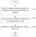
- a wireless communication method for a base station side includes the following steps:
- the distribution of the user equipment is obtained, and the channel state information reference signal CSI-RS mechanism to be employed is determined based on the distribution of the user equipment.
- indication information is generated, which is used to indicate to the user equipment the CSI-RS mechanism to be employed.
- control transmits a CSI-RS to the user equipment.
- embodiments of the present invention also include a wireless communication device on the user equipment side and a wireless communication method, and some aspects of these embodiments correspond to the above-described base station side apparatus and method, and thus a detailed description of these aspects is omitted.
- a wireless communication device 400 for a user equipment side in accordance with one embodiment includes one or more processors 410.
- the processor 410 includes a parsing unit 411 and a control unit 413.
- the parsing unit 411 is configured to parse the indication information from the base station, the indication information indicating a CSI-RS mechanism to be employed.
- the CSI-RS mechanism may be selected from a beamforming CSI-RS and a non-precoding CSI-RS. More specifically, the CSI-RS mechanism may be determined, for example, by the base station side according to the density of users in the area in which the user equipment is located.
- Control unit 413 is configured to control measurements of CSI-RS from the base station in accordance with the indicated CSI-RS mechanism. Further, the control unit 413 is further configured to control transmission of an uplink signal providing directional information to the base station.
- control unit 413 may be further configured to control transmitting a sounding reference signal (SRS) to the base station, wherein the SRS includes directionality information of the user equipment.
- SRS sounding reference signal
- the SRS can be used by the base station to determine the distribution of user equipment within the predetermined area, thereby determining the CSI-RS mechanism to be employed.
- control unit 413 can be configured to control to periodically issue an SRS.
- the base station can also obtain the user equipment distribution through the demodulation reference signal (DMRS) transmitted by the user equipment.
- DMRS demodulation reference signal
- the base station may also configure the non-precoded CSI-RS resource for the user equipment, and the user equipment may obtain the user equipment distribution by feeding back the CSI corresponding to the non-precoded CSI-RS resources.
- control unit 413 may be further configured to perform control to: generate a channel state information CSI report based on the measurement of the CSI-RS from the base station according to the CSI-RS mechanism indicated by the base station .
- the generated CSI report may include a channel quality indication; for the non-precoded CSI-RS, the generated CSI report may include a channel quality indicator, a rank indication, and a precoding matrix indication.
- control unit 413 may be further configured to control transmitting the generated CSI report to the base station.
- the CSI report of the configured CSI-RS resource may be sent according to the indicated CSI-RS mechanism.
- CSI-RS resource sub-corresponding to beamforming CSI-RS and non-precoding CSI-RS Sets can be orthogonal to each other to reduce interference between different CSI-RS mechanisms.
- FIG. 5 shows a configuration example of a wireless communication device for a user equipment side according to another embodiment.
- the wireless communication device 500 for the user equipment side includes one or more processors 510.
- the processor 410 includes a parsing unit 511, a selecting unit 513, and a control unit 515.
- the parsing unit 511 and the control unit 515 are respectively similar to the parsing unit 411 and the control unit 413 described above with reference to FIG. 4, and detailed description thereof will not be repeated here.
- the selecting unit 513 is configured to select a port for transmitting the CSI report based on information from the base station indicating the number of ports of the CSI-RS resource for the corresponding CSI-RS mechanism.
- the selecting unit 513 may select a port for transmitting the CSI report from the first group of ports from the minimum port number of the CSI-RS resource.
- the port for transmitting the CSI report may be selected from the second group of ports from the maximum port number of the CSI-RS resource in response to specific signaling from the base station (eg, the aforementioned signaling NP-portindicator).
- FIG. 6 shows an example of a procedure for a wireless communication method for a user equipment side according to an embodiment of the present invention.
- control transmits an uplink signal that provides directional information to the base station.
- the uplink signal includes, for example, an SRS, and the directional information includes, for example, an angle of arrival.
- the indication information from the base station is parsed, the indication information indicating a channel state information reference signal CSI-RS mechanism to be employed.
- measurements of CSI-RS from the base station are controlled according to the indicated CSI-RS mechanism.
- the embodiment of the present invention further includes a wireless communication device for the base station side as shown in FIG. 7, and a wireless communication device for the user equipment side as shown in FIG.
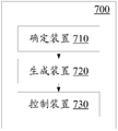
- a wireless communication device 700 for a base station side includes a determining device 710, a generating device 720, and a controlling device 730.
- the determining means 710 is configured to determine a channel state information reference signal CSI-RS mechanism to be employed.
- the generating means 720 is configured to generate indication information for indicating to the user equipment the CSI-RS mechanism to be employed.
- Control device 730 is configured to control transmitting CSI-RS to the user equipment in accordance with the CSI-RS mechanism.
- a wireless communication device 800 package for a user equipment side according to an embodiment
- the analysis device 810 and the control device 820 are included.
- the parsing device 810 is configured to parse the indication information from the base station, the indication information indicating a channel state information reference signal CSI-RS mechanism to be employed.
- Control device 820 is configured to control measurements of CSI-RS from the base station in accordance with the indicated CSI-RS mechanism.
- the various steps of the above methods, as well as the various constituent modules and/or units of the above-described apparatus may be implemented as software, firmware, hardware or a combination thereof.
- a program constituting software for implementing the above method may be installed from a storage medium or a network to a computer having a dedicated hardware structure (for example, the general-purpose computer 900 shown in FIG. 9), which is installed.
- a dedicated hardware structure for example, the general-purpose computer 900 shown in FIG. 9
- an arithmetic processing unit (i.e., CPU) 901 executes various processes in accordance with a program stored in a read only memory (ROM) 902 or a program loaded from a storage portion 908 to a random access memory (RAM) 903.
- ROM read only memory
- RAM random access memory
- data required when the CPU 901 executes various processes and the like is also stored as needed.
- the CPU 901, the ROM 902, and the RAM 903 are linked to each other via a bus 904.
- Input/output interface 905 is also linked to bus 904.
- the following components are linked to an input/output interface 905: an input portion 906 (including a keyboard, a mouse, etc.), an output portion 907 (including a display such as a cathode ray tube (CRT), a liquid crystal display (LCD), etc., and a speaker, etc.)
- the storage portion 908 (including a hard disk or the like), the communication portion 909 (including a network interface card such as a LAN card, a modem, etc.).
- the communication section 909 performs communication processing via a network such as the Internet.
- Driver 910 can also be linked to input/output interface 905 as needed.
- a removable medium 911 such as a magnetic disk, an optical disk, a magneto-optical disk, a semiconductor memory or the like is mounted on the drive 910 as needed, so that a computer program read therefrom is installed into the storage portion 908 as needed.
- a program constituting the software is installed from a network such as the Internet or a storage medium such as the removable medium 911.
- such a storage medium is not limited to the removable medium 911 shown in FIG. 9 in which a program is stored and distributed separately from the device to provide a program to the user.
- the detachable medium 911 include a magnetic disk (including a floppy disk (registered trademark)), an optical disk (including a compact disk read only memory (CD-ROM) and a digital versatile disk (DVD)), and a magneto-optical disk (including a mini disk (MD) (registered trademark) )) and semiconductor memory.
- the storage medium may be a ROM 902, a hard disk included in the storage portion 908, or the like, in which programs are stored, and distributed to the user together with the device containing them.
- Embodiments of the present invention also relate to a program product for storing a machine readable instruction code.
- the instruction code is read and executed by a machine, the above-described method according to an embodiment of the present invention can be performed.
- a storage medium for carrying a program product storing the above-described storage machine readable instruction code is also included in the disclosure of the present invention.
- the storage medium includes, but is not limited to, a floppy disk, an optical disk, a magneto-optical disk, a memory card, a memory stick, and the like.
- Embodiments of the present application also relate to the following electronic devices.
- the electronic device can be implemented as any type of evolved Node B (eNB), such as a macro eNB and a small eNB.
- the small eNB may be an eNB covering a cell smaller than the macro cell, such as a pico eNB, a micro eNB, and a home (femto) eNB.
- the electronic device can be implemented as any other type of base station, such as a NodeB and a base transceiver station (BTS).
- BTS base transceiver station
- the electronic device can include: a body (also referred to as a base station device) configured to control wireless communication; and one or more remote wireless headends (RRHs) disposed at a different location than the body.
- a body also referred to as a base station device
- RRHs remote wireless headends
- various types of terminals which will be described below, can operate as a base station by performing base station functions temporarily or semi-persistently.
- the electronic device can be implemented as a mobile terminal (such as a smart phone, a tablet personal computer (PC), a notebook PC, a portable game terminal, a portable/encrypted dog type mobile router, and a digital camera device) or Vehicle terminal (such as car navigation equipment).
- the electronic device may be a wireless communication module (such as an integrated circuit module including a single or a plurality of wafers) mounted on each of the above terminals.
- FIG. 10 is a block diagram showing an example of a schematic configuration of a smartphone 2500 to which the technology of the present disclosure can be applied.
- the smart phone 2500 includes a processor 2501, a memory 2502, a storage device 2503, an external connection interface 2504, an imaging device 2506, a sensor 2507, a microphone 2508, an input device 2509, a display device 2510, a speaker 2511, a wireless communication interface 2512, and one or more An antenna switch 2515, one or more antennas 2516, a bus 2517, a battery 2518, and an auxiliary controller 2519.
- the processor 2501 may be, for example, a CPU or a system on chip (SoC), and controls the functions of the application layer and the other layers of the smartphone 2500.
- the memory 2502 includes a RAM and a ROM, and stores data and programs executed by the processor 2501.
- the storage device 2503 may include a storage medium such as a semiconductor memory and a hard disk.
- the external connection interface 2504 is an interface for connecting an external device such as a memory card and a universal serial bus (USB) device to the smartphone 2500.
- USB universal serial bus
- the image pickup device 2506 includes an image sensor such as a charge coupled device (CCD) and a complementary metal oxide semiconductor (CMOS), and generates a captured image.
- Sensor 2507 can include a set of sensors, such as a measurement sensor, a gyro sensor, a geomagnetic sensor, and an acceleration sensor.
- the microphone 2508 converts the sound input to the smartphone 2500 into an audio signal.
- the input device 2509 includes, for example, a touch sensor, a keypad, a keyboard, a button, or a switch configured to detect a touch on the screen of the display device 2510, and receives an operation or information input from a user.
- the display device 2510 includes screens such as a liquid crystal display (LCD) and an organic light emitting diode (OLED) display, and displays an output image of the smartphone 2500.
- the speaker 2511 converts the audio signal output from the smartphone 2500 into a sound.
- the wireless communication interface 2512 supports any cellular communication scheme (such as LTE and LTE-A) and performs wireless communication.
- Wireless communication interface 2512 may generally include, for example, a baseband (BB) processor 2513 and radio frequency (RF) circuitry 2514.
- the BB processor 2513 can perform, for example, encoding/decoding, modulation/demodulation, and multiplexing/demultiplexing, and performs various types of signal processing for wireless communication.
- the RF circuit 2514 may include, for example, a mixer, a filter, and an amplifier, and transmits and receives a wireless signal via the antenna 2516.
- the wireless communication interface 2512 can be a chip module on which the BB processor 2513 and the RF circuit 2514 are integrated. As shown in FIG.
- the wireless communication interface 2512 can include a plurality of BB processors 2513 and a plurality of RF circuits 2514.
- FIG. 10 illustrates an example in which the wireless communication interface 2512 includes a plurality of BB processors 2513 and a plurality of RF circuits 2514, the wireless communication interface 2512 may also include a single BB processor 2513 or a single RF circuit 2514.
- wireless communication interface 2512 can support additional types of wireless communication schemes, such as short-range wireless communication schemes, near field communication schemes, and wireless local area network (LAN) schemes.
- the wireless communication interface 2512 can include a BB processor 2513 and RF circuitry 2514 for each wireless communication scheme.
- Each of the antenna switches 2515 switches the connection destination of the antenna 2516 between a plurality of circuits included in the wireless communication interface 2512, such as circuits for different wireless communication schemes.
- Each of the antennas 2516 includes a single or multiple antenna elements (such as multiple antenna elements included in a MIMO antenna) and is used by the wireless communication interface 2512 to transmit and receive wireless signals.
- smart phone 2500 can include multiple antennas 2516.
- FIG. 13 shows an example in which the smartphone 2500 includes a plurality of antennas 2516, the smartphone 2500 may also include a single antenna 2516.
- smart phone 2500 can include an antenna 2516 for each wireless communication scheme.
- the antenna switch 2515 can be omitted from the configuration of the smartphone 2500.
- the bus 2517 includes a processor 2501, a memory 2502, a storage device 2503, an external connection interface 2504, an imaging device 2506, a sensor 2507, a microphone 2508, an input device 2509, and a display device.
- the setting 2510, the speaker 2511, the wireless communication interface 2512, and the auxiliary controller 2519 are connected to each other.
- Battery 2518 provides power to various blocks of smart phone 2500 shown in FIG. 13 via feeders, which are partially shown as dashed lines in the figure.
- the secondary controller 2519 operates the minimum required function of the smartphone 2500, for example, in a sleep mode.
- At least a portion of the functions of the units described with reference to FIGS. 4 and 5 may also be implemented by the processor 2501 or the auxiliary controller 2519.
- the power consumption of the battery 2518 can be reduced by performing a portion of the functions of the processor 2501 by the auxiliary controller 2519.
- the processor 2501 or the auxiliary controller 2519 can perform at least a part of the functions of the units described with reference to FIGS. 4 and 5 by executing the program stored in the memory 2502 or the storage device 2503.
- the eNB 2300 includes one or more antennas 2310 and base station devices 2320.
- the base station device 2320 and each antenna 2310 may be connected to each other via a radio frequency (RF) cable.
- RF radio frequency
- Each of the antennas 2310 includes a single or multiple antenna elements, such as multiple antenna elements included in a multiple input multiple output (MIMO) antenna, and is used by the base station device 2320 to transmit and receive wireless signals.
- the eNB 2300 may include a plurality of antennas 2310.
- multiple antennas 2310 can be compatible with multiple frequency bands used by eNB 2300.
- FIG. 11 illustrates an example in which the eNB 2300 includes a plurality of antennas 2310, the eNB 2300 may also include a single antenna 2310.
- the base station device 2320 includes a controller 2321, a memory 2322, a network interface 2323, and a wireless communication interface 2325.
- the controller 2321 can be, for example, a CPU or a DSP, and operates various functions of higher layers of the base station device 2320. For example, controller 2321 generates data packets based on data in signals processed by wireless communication interface 2325 and delivers the generated packets via network interface 2323. The controller 2321 can bundle data from a plurality of baseband processors to generate bundled packets and deliver the generated bundled packets. The controller 2321 may have a logical function that performs control such as radio resource control, radio bearer control, mobility management, admission control, and scheduling. This control can be performed in conjunction with nearby eNBs or core network nodes.
- the memory 2322 includes a RAM and a ROM, and stores programs executed by the controller 2321 and various types of control data such as a terminal list, transmission power data, and scheduling data.
- the network interface 2323 is a communication interface for connecting the base station device 2320 to the core network 2324.
- the controller 2321 can communicate with the core network node or another eNB via the network interface 2323 letter.
- the eNB 2300 and the core network node or other eNBs may be connected to each other through a logical interface such as an S1 interface and an X2 interface.
- the network interface 2323 can also be a wired communication interface or a wireless communication interface for wireless backhaul lines. If the network interface 2323 is a wireless communication interface, the network interface 2323 can use a higher frequency band for wireless communication than the frequency band used by the wireless communication interface 2325.
- the wireless communication interface 2325 supports any cellular communication schemes, such as Long Term Evolution (LTE) and LTE-Advanced, and provides wireless connectivity to terminals located in cells of the eNB 2300 via the antenna 2310.
- Wireless communication interface 2325 can typically include, for example, BB processor 2326 and RF circuitry 2327.
- the BB processor 2326 can perform, for example, encoding/decoding, modulation/demodulation, and multiplexing/demultiplexing, and performs layers (eg, L1, Medium Access Control (MAC), Radio Link Control (RLC), and Packet Data Convergence Protocol (PDCP)) Various types of signal processing.
- BB processor 2326 may have some or all of the above described logic functions.
- the BB processor 2326 can be a memory that stores a communication control program, or a module that includes a processor and associated circuitry configured to execute the program.
- the update program can cause the functionality of the BB processor 2326 to change.
- the module can be a card or blade that is inserted into the slot of the base station device 2320. Alternatively, the module can also be a chip mounted on a card or blade.
- the RF circuit 2327 may include, for example, a mixer, a filter, and an amplifier, and transmits and receives a wireless signal via the antenna 2310.
- the wireless communication interface 2325 can include a plurality of BB processors 2326.
- multiple BB processors 2326 can be compatible with multiple frequency bands used by eNB 2300.
- the wireless communication interface 2325 can include a plurality of RF circuits 2327.
- multiple RF circuits 2327 can be compatible with multiple antenna elements.
- FIG. 11 illustrates an example in which the wireless communication interface 2325 includes a plurality of BB processors 2326 and a plurality of RF circuits 2327, the wireless communication interface 2325 may also include a single BB processor 2326 or a single RF circuit 2327.
- At least a part of the functions of the units described with reference to FIGS. 1 and 2 may also be controlled by the controller 221.
- the controller 2321 can perform at least a portion of the functions of the units described with reference to FIGS. 1 and 2 by executing a program stored in the memory 2322.
- the method of the present invention is not limited to being performed in the chronological order described in the specification, and may be performed in other chronological order, in parallel, or independently. Therefore, the order of execution of the methods described in the present specification does not limit the technical scope of the present invention.
Landscapes
- Engineering & Computer Science (AREA)
- Signal Processing (AREA)
- Computer Networks & Wireless Communication (AREA)
- Quality & Reliability (AREA)
- Mobile Radio Communication Systems (AREA)
Abstract
Description


Claims (28)
- 一种用于基站侧的无线通信设备,包括:一个或更多个处理器,被配置为获得用户设备的分布情况;基于所述用户设备的分布情况确定要采用的信道状态信息参考信号CSI-RS机制;生成指示信息,所述指示信息用于向用户设备指示所要采用的CSI-RS机制;以及根据所述CSI-RS机制,控制向所述用户设备发送CSI-RS。
- 根据权利要求1所述的无线通信设备,其中,确定所述CSI-RS机制包括选择波束赋形CSI-RS和非预编码CSI-RS之一。
- 根据权利要求2所述的无线通信设备,其中,获得所述用户设备的分布情况包括:基于由所述用户设备的上行信号得出的方向性信息估计所述用户设备的分布情况。
- 根据权利要求3所述的无线通信设备,其中,所述上行信号包括探测参考信号,所述方向性信息包括所述探测参考信号的到达角。
- 根据权利要求2所述的无线通信设备,其中,所述分布情况指示用户密度,所述选择包括:在用户密度高于预定水平的情况下,选择非预编码CSI-RS,在用户密度低于预定水平的情况下,选择波束赋形CSI-RS。
- 根据权利要求5所述的无线通信设备,其中,所述预定水平与所述波束赋形CSI-RS的空间分辨率有关。
- 根据权利要求3所述的无线通信设备,其中,所述选择包括:根据用户设备在所述基站的小区的子区域中的分布情况,分别针对各个子区域选择相应的CSI-RS机制。
- 根据权利要求7所述的无线通信设备,其中,所述选择包括:对于用户密度高于预定水平的所述子区域,选择非预编码CSI-RS;对于用户密度低于预定水平的所述子区域,选择波束赋形CSI-RS。
- 根据权利要求2所述的无线通信设备,其中,所述处理器还被配置为:控制对来自用户设备的信道状态信息CSI报告的接收和/或解析,其中,对于波束赋形CSI-RS,所述CSI报告包含信道质量指示而不包含秩指示和预编码矩阵指示,对于非预编码CSI-RS,所述CSI报告包含信道质量指示、秩指示和预编码矩阵指示中至少之一。
- 根据权利要求2所述的无线通信设备,其中,所述处理器还被配置为:将所述指示信息包含在无线资源控制信令中。
- 根据权利要求2所述的无线通信设备,其中,所述处理器还被配置为:分别针对波束赋形CSI-RS和非预编码CSI-RS设置相应的CSI-RS资源子集。
- 根据权利要求11所述的无线通信设备,其中,设置相应的CSI-RS资源子集包括:将针对波束赋形CSI-RS设置的CSI-RS资源子集和针对非预编码CSI-RS设置的CSI-RS资源子集设置为彼此正交。
- 根据权利要求11所述的无线通信设备,其中,设置相应的CSI-RS资源子集包括:根据采用波束赋形CSI-RS用户设备的数量来设置用于波束赋形CSI-RS的端口数量。
- 根据权利要求13所述的无线通信设备,其中,所述处理器还被配置为:生成用于向用户设备指示用于相应CSI-RS机制的端口数量的信息。
- 根据权利要求11所述的无线通信设备,其中,设置相应的CSI-RS资源子集包括:将从CSI-RS资源的最小端口号起的第一组端口分配给波束赋形CSI-RS和非预编码CSI-RS之一,将从CSI-RS资源的最大端口号起的第二组端口分配给波束赋形CSI-RS和非预编码CSI-RS中的另一个。
- 根据权利要求15所述的无线通信设备,其中,所述处理器还被配置为:在所要采用的CSI-RS机制对应于所述第二组端口的情况下,生成用于向用户设备指示从CSI-RS资源的最大端口号起选择端口的信令。
- 根据权利要求11所述的无线通信设备,其中,设置相应的CSI-RS资源子集包括:根据多个预定方式之一分配用于相应CSI-RS机制的端口,并且所述处理器还被配置为:生成用于向用户设备指示所采用的所述预定方式的指示信息。
- 一种用于基站侧的无线通信方法,包括:获得用户设备的分布情况;基于所述用户设备的分布情况确定要采用的信道状态信息参考信号CSI-RS机制;生成指示信息,所述指示信息用于向用户设备指示所要采用的CSI-RS机制;以及根据所述CSI-RS机制,控制向所述用户设备发送CSI-RS。
- 一种用于用户设备侧的无线通信设备,包括:一个或更多个处理器,被配置为控制向基站发送提供方向性信息的上行信号;解析来自基站的指示信息,所述指示信息指示要采用的信道状态信息参考信号CSI-RS机制;以及根据所指示的CSI-RS机制,控制对来自所述基站的CSI-RS的测量。
- 根据权利要求19所述的无线通信设备,其中,所述CSI-RS机制选自波束赋形CSI-RS和非预编码CSI-RS。
- 根据权利要求20所述的无线通信设备,其中,所述上行信号包括探测参考信号。
- 根据权利要求20所述的无线通信设备,其中,所述处理器还被配置为:根据所指示的CSI-RS机制,基于对来自所述基站的CSI-RS的测量来生成信道状态信息CSI报告,其中,对于波束赋形CSI-RS,所述CSI报告包含信道质量指示而不包含秩指示和预编码矩阵指示。
- 根据权利要求22所述的无线通信设备,其中,所述处理器还被配置为:控制向基站发送所述CSI报告,其中,根据所指示的CSI-RS机制,报告相应CSI-RS资源子集的CSI。
- 根据权利要求23所述的无线通信设备,其中,针对波束赋形CSI-RS设置的CSI-RS资源子集和针对非预编码CSI-RS设置的CSI-RS资源子集被设置为彼此正交。
- 根据权利要求24所述的无线通信设备,其中,所述处理器还被配置为:基于来自所述基站的指示用于相应CSI-RS机制的CSI-RS资源的端口数量的信息,确定所述用户设备分配到的相应CSI-RS机制的CSI-RS端口。
- 根据权利要求25所述的无线通信设备,其中,确定所述CSI-RS端口包括:从CSI-RS资源的最小端口号起的第一组端口中中确定所述CSI-RS端口;或者响应于来自所述基站的特定信令,从CSI-RS资源的最大端口号起的第二组端口中确定所述CSI-RS端口。
- 根据权利要求24所述的无线通信设备,其中,所述处理器还被配置为:基于来自基站的关于多个预定方式之一的指示信息,根据所指示的预定方式来确定所述用户设备分配到的相应CSI-RS机制的CSI-RS端口。
- 一种用于用户设备侧的无线通信方法,包括:控制向基站发送提供方向性信息的上行信号;解析来自基站的指示信息,所述指示信息指示要采用的信道状态信息参考信号CSI-RS机制;以及根据所指示的CSI-RS机制,控制对来自所述基站的CSI-RS的测量。
Priority Applications (7)
| Application Number | Priority Date | Filing Date | Title |
|---|---|---|---|
| CA3004142A CA3004142C (en) | 2015-11-06 | 2016-10-31 | Wireless communication device and wireless communication method for channel state information reference signal mechanism selection and measurement |
| EP16861518.5A EP3373632B1 (en) | 2015-11-06 | 2016-10-31 | Wireless communication device and wireless communication method |
| US15/770,664 US10651911B2 (en) | 2015-11-06 | 2016-10-31 | Wireless communication device and wireless communication method |
| AU2016350973A AU2016350973B2 (en) | 2015-11-06 | 2016-10-31 | Wireless communication device and wireless communication method |
| EP20157362.3A EP3678405B1 (en) | 2015-11-06 | 2016-10-31 | Wireless communication device and wireless communication method |
| KR1020187015621A KR102714832B1 (ko) | 2015-11-06 | 2016-10-31 | 무선 통신 디바이스 및 무선 통신 방법 |
| US16/819,171 US11223406B2 (en) | 2015-11-06 | 2020-03-16 | Wireless communication device and wireless communication method |
Applications Claiming Priority (2)
| Application Number | Priority Date | Filing Date | Title |
|---|---|---|---|
| CN201510753149.1A CN106686620B (zh) | 2015-11-06 | 2015-11-06 | 无线通信设备和无线通信方法 |
| CN201510753149.1 | 2015-11-06 |
Related Child Applications (2)
| Application Number | Title | Priority Date | Filing Date |
|---|---|---|---|
| US15/770,664 A-371-Of-International US10651911B2 (en) | 2015-11-06 | 2016-10-31 | Wireless communication device and wireless communication method |
| US16/819,171 Division US11223406B2 (en) | 2015-11-06 | 2020-03-16 | Wireless communication device and wireless communication method |
Publications (1)
| Publication Number | Publication Date |
|---|---|
| WO2017076250A1 true WO2017076250A1 (zh) | 2017-05-11 |
Family
ID=58661647
Family Applications (1)
| Application Number | Title | Priority Date | Filing Date |
|---|---|---|---|
| PCT/CN2016/103994 Ceased WO2017076250A1 (zh) | 2015-11-06 | 2016-10-31 | 无线通信设备和无线通信方法 |
Country Status (7)
| Country | Link |
|---|---|
| US (2) | US10651911B2 (zh) |
| EP (2) | EP3373632B1 (zh) |
| KR (1) | KR102714832B1 (zh) |
| CN (1) | CN106686620B (zh) |
| AU (1) | AU2016350973B2 (zh) |
| CA (1) | CA3004142C (zh) |
| WO (1) | WO2017076250A1 (zh) |
Cited By (1)
| Publication number | Priority date | Publication date | Assignee | Title |
|---|---|---|---|---|
| CN116326044A (zh) * | 2020-10-02 | 2023-06-23 | 苹果公司 | 信道状态信息报告 |
Families Citing this family (15)
| Publication number | Priority date | Publication date | Assignee | Title |
|---|---|---|---|---|
| WO2017075821A1 (zh) * | 2015-11-06 | 2017-05-11 | 华为技术有限公司 | 一种信道状态信息的测量与反馈方法、用户设备及基站 |
| JP7242161B2 (ja) * | 2017-06-14 | 2023-03-20 | ソニーグループ株式会社 | 通信装置、通信制御方法及びコンピュータプログラム |
| WO2019061260A1 (zh) | 2017-09-29 | 2019-04-04 | 华为技术有限公司 | 一种测量方法、网络设备和终端设备 |
| US11108476B2 (en) * | 2017-10-17 | 2021-08-31 | Intel Corporation | Techniques in beam measurement |
| CN110289896A (zh) * | 2018-03-15 | 2019-09-27 | 索尼公司 | 电子装置、无线通信方法以及计算机可读介质 |
| CN110958042A (zh) | 2018-09-26 | 2020-04-03 | 索尼公司 | 网络侧设备、用户设备、无线通信方法和存储介质 |
| WO2020154832A1 (en) * | 2019-01-28 | 2020-08-06 | Qualcomm Incorporated | Hybrid channel state feedback |
| CN113748632B (zh) * | 2019-04-25 | 2023-05-05 | 华为技术有限公司 | 信道状态信息参考信号的配置方法和装置 |
| US10797762B1 (en) * | 2019-07-31 | 2020-10-06 | Sprint Spectrum L.P. | Beamforming in massive MIMO networks |
| US12301495B2 (en) | 2020-02-12 | 2025-05-13 | Nokia Solutions And Networks Oy | Method and apparatus for controlling operation of user device |
| US11785637B2 (en) * | 2020-04-29 | 2023-10-10 | Qualcomm Incorporated | Multiple channel state feedback reports for MU-MIMO scheduling assistance |
| CN117880902A (zh) * | 2020-10-22 | 2024-04-12 | 大唐移动通信设备有限公司 | 小区切换方法、终端、基站、装置和存储介质 |
| CN113298971B (zh) * | 2021-05-08 | 2022-09-02 | 西安图迹信息科技有限公司 | 考虑多设备间无线信号干扰的发电厂巡检方法和系统 |
| US12512891B2 (en) | 2022-03-10 | 2025-12-30 | Samsung Electronics Co., Ltd. | Wireless communication device transmitting and receiving data using channel state information feedback and operating method thereof |
| CN115119314A (zh) * | 2022-06-30 | 2022-09-27 | 西安交通大学 | 一种卫星通信系统的动态波束资源分配方法 |
Citations (4)
| Publication number | Priority date | Publication date | Assignee | Title |
|---|---|---|---|---|
| CN101714897A (zh) * | 2009-11-12 | 2010-05-26 | 普天信息技术研究院有限公司 | 探测参考信号的配置方法 |
| CN102448088A (zh) * | 2010-09-30 | 2012-05-09 | 华为技术有限公司 | 测量资源指示的方法、测量方法和装置 |
| CN103891183A (zh) * | 2011-09-06 | 2014-06-25 | Lg电子株式会社 | 用于测量无线通信系统中的干扰的方法和设备 |
| CN105991222A (zh) * | 2015-02-12 | 2016-10-05 | 中兴通讯股份有限公司 | 配置信息通知方法、获取方法、装置、基站及终端 |
Family Cites Families (27)
| Publication number | Priority date | Publication date | Assignee | Title |
|---|---|---|---|---|
| KR101417084B1 (ko) * | 2008-07-02 | 2014-08-07 | 엘지전자 주식회사 | 상향링크 전송을 위한 기준신호 전송 방법 |
| US20110244877A1 (en) * | 2009-10-08 | 2011-10-06 | Qualcomm Incorporated | Method and apparatus for using channel state information reference signal in wireless communication system |
| CN102158874B (zh) * | 2010-02-12 | 2014-04-30 | 华为技术有限公司 | 信道测量的方法和装置 |
| WO2011115421A2 (en) | 2010-03-17 | 2011-09-22 | Lg Electronics Inc. | Method and apparatus for providing channel state information-reference signal (csi-rs) configuration information in a wireless communication system supporting multiple antennas |
| JP5345111B2 (ja) * | 2010-08-16 | 2013-11-20 | 株式会社エヌ・ティ・ティ・ドコモ | Csi−rsのシグナリング方法及び基地局装置 |
| CA2834270C (en) * | 2011-05-02 | 2016-11-15 | Blackberry Limited | Methods and systems of wireless communication with remote radio heads |
| KR101767997B1 (ko) * | 2011-06-24 | 2017-08-14 | 삼성전자 주식회사 | 직교 주파수 분할 다중 접속 이동통신 시스템을 기반으로 하는 분산 안테나 시스템에서 하향링크 간섭 측정 방법 및 장치 |
| US20130064216A1 (en) * | 2011-09-12 | 2013-03-14 | Research In Motion Limited | DMRS Association and Signaling for Enhanced PDCCH in LTE Systems |
| US9363056B2 (en) * | 2011-09-28 | 2016-06-07 | Lg Electronics Inc. | Method and apparatus for setting plurality of reference signal configurations in wireless communication system |
| WO2013111422A1 (ja) * | 2012-01-26 | 2013-08-01 | ソニー株式会社 | 無線通信装置及び無線通信方法、並びに無線通信システム |
| JP6097766B2 (ja) * | 2012-01-27 | 2017-03-15 | インターデイジタル パテント ホールディングス インコーポレイテッド | マルチキャリアベースおよび/または疑似照合ネットワークにおいてepdcchを提供するためのシステムおよび/または方法 |
| US9544876B2 (en) * | 2012-03-16 | 2017-01-10 | Intel Corporation | Downlink control information (DCI) validation for enhanced physical downlink control channel (ePDCCH) |
| US9414371B2 (en) * | 2012-04-16 | 2016-08-09 | Samsung Electronics Co., Ltd. | Hierarchical channel sounding and channel state information feedback in massive MIMO systems |
| US9681425B2 (en) * | 2012-05-11 | 2017-06-13 | Qualcomm Incorporated | Rank-specific feedback for improved MIMO support |
| US8982693B2 (en) * | 2012-05-14 | 2015-03-17 | Google Technology Holdings LLC | Radio link monitoring in a wireless communication device |
| US9198070B2 (en) * | 2012-05-14 | 2015-11-24 | Google Technology Holdings LLC | Radio link monitoring in a wireless communication device |
| US20130343299A1 (en) * | 2012-06-21 | 2013-12-26 | Samsung Electronics Co., Ltd | Method for cqi feedback without spatial feedback (pmi/ri) for tdd coordinated multi-point and carrier aggregation scenarios |
| US9225478B2 (en) * | 2012-07-02 | 2015-12-29 | Intel Corporation | Supporting measurments and feedback for 3D MIMO with data transmission optimization |
| US20140029458A1 (en) * | 2012-07-24 | 2014-01-30 | Acer Incorporated | Apparatuses and methods for signaling coordinated multi-point (comp) measurement configuration |
| US9106386B2 (en) * | 2012-08-03 | 2015-08-11 | Intel Corporation | Reference signal configuration for coordinated multipoint |
| US9184889B2 (en) * | 2012-08-08 | 2015-11-10 | Blackberry Limited | Method and system having reference signal design for new carrier types |
| US9439096B2 (en) * | 2012-08-13 | 2016-09-06 | Samsung Electronics Co., Ltd. | Method and apparatus to support channel refinement and multi-stream transmission in millimeter wave systems |
| US9520963B2 (en) * | 2013-03-22 | 2016-12-13 | Telefonaktiebolaget Lm Ericsson (Publ) | Modulation and coding scheme selection for link adaptation |
| JP6374510B2 (ja) * | 2013-09-11 | 2018-08-15 | 華為技術有限公司Huawei Technologies Co.,Ltd. | チャネル状態情報参照信号を構成するための方法、および基地局 |
| US9973249B2 (en) * | 2014-12-23 | 2018-05-15 | Samsung Electronics Co., Ltd. | Channel state information feedback schemes for FD-MIMO |
| EP3269046A4 (en) * | 2015-03-13 | 2018-04-25 | Samsung Electronics Co., Ltd. | Advanced feedback and reference signal transmissions for mimo wireless communication systems |
| US10547366B2 (en) * | 2015-09-04 | 2020-01-28 | Samsung Electronics Co., Ltd. | Method and apparatus for CSI reporting on PUCCH |
-
2015
- 2015-11-06 CN CN201510753149.1A patent/CN106686620B/zh active Active
-
2016
- 2016-10-31 WO PCT/CN2016/103994 patent/WO2017076250A1/zh not_active Ceased
- 2016-10-31 AU AU2016350973A patent/AU2016350973B2/en not_active Ceased
- 2016-10-31 CA CA3004142A patent/CA3004142C/en not_active Expired - Fee Related
- 2016-10-31 EP EP16861518.5A patent/EP3373632B1/en active Active
- 2016-10-31 KR KR1020187015621A patent/KR102714832B1/ko active Active
- 2016-10-31 EP EP20157362.3A patent/EP3678405B1/en active Active
- 2016-10-31 US US15/770,664 patent/US10651911B2/en active Active
-
2020
- 2020-03-16 US US16/819,171 patent/US11223406B2/en active Active
Patent Citations (4)
| Publication number | Priority date | Publication date | Assignee | Title |
|---|---|---|---|---|
| CN101714897A (zh) * | 2009-11-12 | 2010-05-26 | 普天信息技术研究院有限公司 | 探测参考信号的配置方法 |
| CN102448088A (zh) * | 2010-09-30 | 2012-05-09 | 华为技术有限公司 | 测量资源指示的方法、测量方法和装置 |
| CN103891183A (zh) * | 2011-09-06 | 2014-06-25 | Lg电子株式会社 | 用于测量无线通信系统中的干扰的方法和设备 |
| CN105991222A (zh) * | 2015-02-12 | 2016-10-05 | 中兴通讯股份有限公司 | 配置信息通知方法、获取方法、装置、基站及终端 |
Non-Patent Citations (1)
| Title |
|---|
| See also references of EP3373632A4 * |
Cited By (1)
| Publication number | Priority date | Publication date | Assignee | Title |
|---|---|---|---|---|
| CN116326044A (zh) * | 2020-10-02 | 2023-06-23 | 苹果公司 | 信道状态信息报告 |
Also Published As
| Publication number | Publication date |
|---|---|
| US20200220599A1 (en) | 2020-07-09 |
| EP3373632A1 (en) | 2018-09-12 |
| EP3373632A4 (en) | 2018-09-12 |
| US20180316404A1 (en) | 2018-11-01 |
| US10651911B2 (en) | 2020-05-12 |
| KR20180079412A (ko) | 2018-07-10 |
| CN106686620A (zh) | 2017-05-17 |
| AU2016350973B2 (en) | 2021-04-01 |
| KR102714832B1 (ko) | 2024-10-10 |
| EP3678405A1 (en) | 2020-07-08 |
| CN106686620B (zh) | 2021-06-22 |
| EP3678405B1 (en) | 2021-12-08 |
| CA3004142C (en) | 2022-06-21 |
| CA3004142A1 (en) | 2017-05-11 |
| US11223406B2 (en) | 2022-01-11 |
| EP3373632B1 (en) | 2020-05-06 |
| AU2016350973A1 (en) | 2018-04-12 |
Similar Documents
| Publication | Publication Date | Title |
|---|---|---|
| CN106686620B (zh) | 无线通信设备和无线通信方法 | |
| US20250317176A1 (en) | Electronic device, method and storage medium for wireless communication system | |
| EP4114083A1 (en) | Electronic device and method for wireless communication, and computer-readable storage medium | |
| US12143188B2 (en) | Network device, user equipment, wireless communication method and storage medium | |
| CN106470096B (zh) | 用于无线通信的基站侧和用户设备侧的装置及方法 | |
| US10574304B2 (en) | Method, system and apparatus of beam selection | |
| US20210083914A1 (en) | Electronic device and method for wireless communication, and computer-readable storage medium | |
| CN107636991B (zh) | 信息传输方法、信息处理方法、基站以及移动台 | |
| WO2019029515A1 (zh) | 用于无线通信的电子设备、方法和介质 | |
| CA3048935A1 (en) | Electronic device, method and storage medium for wireless communication system | |
| CN106416346B (zh) | 设备和方法 | |
| CN106559120A (zh) | 无线通信系统中的电子设备和无线通信方法 | |
| JP7268676B2 (ja) | 電子装置 | |
| WO2016155571A1 (zh) | 用于无线通信的装置和方法 | |
| JP2021532657A (ja) | ユーザ機器、電子機器、無線通信方法及び記憶媒体 | |
| WO2022037467A1 (zh) | 电子设备、无线通信方法和计算机可读存储介质 | |
| WO2021027802A1 (zh) | 用于无线通信系统的电子设备、方法和存储介质 |
Legal Events
| Date | Code | Title | Description |
|---|---|---|---|
| 121 | Ep: the epo has been informed by wipo that ep was designated in this application |
Ref document number: 16861518 Country of ref document: EP Kind code of ref document: A1 |
|
| ENP | Entry into the national phase |
Ref document number: 2016350973 Country of ref document: AU Date of ref document: 20161031 Kind code of ref document: A |
|
| WWE | Wipo information: entry into national phase |
Ref document number: 15770664 Country of ref document: US |
|
| ENP | Entry into the national phase |
Ref document number: 3004142 Country of ref document: CA |
|
| NENP | Non-entry into the national phase |
Ref country code: DE |
|
| ENP | Entry into the national phase |
Ref document number: 20187015621 Country of ref document: KR Kind code of ref document: A |
|
| WWE | Wipo information: entry into national phase |
Ref document number: 2016861518 Country of ref document: EP |