WO2017077821A1 - 積層鉄心の製造方法 - Google Patents
積層鉄心の製造方法 Download PDFInfo
- Publication number
- WO2017077821A1 WO2017077821A1 PCT/JP2016/080134 JP2016080134W WO2017077821A1 WO 2017077821 A1 WO2017077821 A1 WO 2017077821A1 JP 2016080134 W JP2016080134 W JP 2016080134W WO 2017077821 A1 WO2017077821 A1 WO 2017077821A1
- Authority
- WO
- WIPO (PCT)
- Prior art keywords
- region
- punching
- magnet housing
- regions
- leading
- Prior art date
- Legal status (The legal status is an assumption and is not a legal conclusion. Google has not performed a legal analysis and makes no representation as to the accuracy of the status listed.)
- Ceased
Links
Images





Classifications
-
- H—ELECTRICITY
- H02—GENERATION; CONVERSION OR DISTRIBUTION OF ELECTRIC POWER
- H02K—DYNAMO-ELECTRIC MACHINES
- H02K15/00—Processes or apparatus specially adapted for manufacturing, assembling, maintaining or repairing of dynamo-electric machines
- H02K15/02—Processes or apparatus specially adapted for manufacturing, assembling, maintaining or repairing of dynamo-electric machines of stator or rotor bodies
- H02K15/03—Processes or apparatus specially adapted for manufacturing, assembling, maintaining or repairing of dynamo-electric machines of stator or rotor bodies having permanent magnets
-
- H—ELECTRICITY
- H01—ELECTRIC ELEMENTS
- H01F—MAGNETS; INDUCTANCES; TRANSFORMERS; SELECTION OF MATERIALS FOR THEIR MAGNETIC PROPERTIES
- H01F41/00—Apparatus or processes specially adapted for manufacturing or assembling magnets, inductances or transformers; Apparatus or processes specially adapted for manufacturing materials characterised by their magnetic properties
- H01F41/02—Apparatus or processes specially adapted for manufacturing or assembling magnets, inductances or transformers; Apparatus or processes specially adapted for manufacturing materials characterised by their magnetic properties for manufacturing cores, coils, or magnets
- H01F41/0206—Manufacturing of magnetic cores by mechanical means
- H01F41/0233—Manufacturing of magnetic circuits made from sheets
-
- H—ELECTRICITY
- H02—GENERATION; CONVERSION OR DISTRIBUTION OF ELECTRIC POWER
- H02K—DYNAMO-ELECTRIC MACHINES
- H02K1/00—Details of the magnetic circuit
- H02K1/06—Details of the magnetic circuit characterised by the shape, form or construction
- H02K1/22—Rotating parts of the magnetic circuit
-
- H—ELECTRICITY
- H02—GENERATION; CONVERSION OR DISTRIBUTION OF ELECTRIC POWER
- H02K—DYNAMO-ELECTRIC MACHINES
- H02K1/00—Details of the magnetic circuit
- H02K1/06—Details of the magnetic circuit characterised by the shape, form or construction
- H02K1/22—Rotating parts of the magnetic circuit
- H02K1/27—Rotor cores with permanent magnets
-
- H—ELECTRICITY
- H02—GENERATION; CONVERSION OR DISTRIBUTION OF ELECTRIC POWER
- H02K—DYNAMO-ELECTRIC MACHINES
- H02K15/00—Processes or apparatus specially adapted for manufacturing, assembling, maintaining or repairing of dynamo-electric machines
- H02K15/02—Processes or apparatus specially adapted for manufacturing, assembling, maintaining or repairing of dynamo-electric machines of stator or rotor bodies
-
- H—ELECTRICITY
- H02—GENERATION; CONVERSION OR DISTRIBUTION OF ELECTRIC POWER
- H02K—DYNAMO-ELECTRIC MACHINES
- H02K2201/00—Specific aspects not provided for in the other groups of this subclass relating to the magnetic circuits
- H02K2201/09—Magnetic cores comprising laminations characterised by being fastened by caulking
Definitions
- the present disclosure relates to a method for manufacturing a laminated iron core constituting a rotor.
- the laminated iron core is a motor part.
- a laminated iron core is formed by stacking a plurality of electromagnetic steel sheets (processed bodies) processed into a predetermined shape and fastening them.
- the motor includes a rotor (rotor) and a stator (stator) each formed of a laminated iron core, and is completed through a process of attaching a shaft to the rotor, a process of winding a coil around the stator, and the like.
- the laminated iron core constituting the rotor has a plurality of poles. Each pole has one or more permanent magnets. These permanent magnets are accommodated in a magnet accommodation area (slot) provided in the laminated iron core.
- a motor having a rotor with such a configuration is called an IPM (Interior Permanent Magnet) motor.
- a rotor composed of a laminated iron core having a magnet housing area a plurality of magnet housing areas are arranged in the circumferential direction at a predetermined interval, and a workpiece in which a fan-shaped main body portion is formed between adjacent magnet housing areas is laminated.
- a rotor is known (see, for example, Patent Document 1).
- a method of manufacturing a laminated iron core constituting a rotor a step of supplying an electromagnetic steel plate (workpiece plate) to a progressive die, a step of producing a workpiece having a predetermined shape by punching in the progressive die, and production
- a method including stacking a plurality of processed bodies to obtain a laminated iron core is known (see, for example, Patent Document 2).
- the present disclosure has been made in view of the above circumstances, and an object of the present disclosure is to suppress deformation due to residual stress in a laminated core of a rotor that is a laminate of processed bodies in which a plurality of magnet housing regions are arranged.
- a method of manufacturing a laminated core includes: (A) a step of supplying a workpiece plate to a mold; and (B) a punching process of the workpiece plate with the die, A step of obtaining a workpiece in which a plurality of magnet housing regions arranged around the annular portion at a predetermined interval in the circumferential direction and a main body portion serving as a magnetic flux path between the plurality of magnet housing regions are formed; And a step of obtaining a laminated iron core by stacking a plurality of the processed bodies and fastening them, and the step (B) includes (b-1) a tip formed in advance in the magnet housing region. A step of forming a punching region; and (b-2) a step of forming a post punching region formed subsequent to the leading punching region in the magnet housing region after the step (b-1).
- the method of manufacturing the laminated core when forming a plurality of magnet housing areas by punching, a pre-punched area is formed first, and then a post-punched area is formed. That is, the magnet housing region is formed in a plurality of steps. Thereby, compared with the case where a magnet accommodation area
- the post-extracted region may be formed so that a part of the post-extracted region overlaps the pre-extracted region. If the punching accuracy of the die is reduced due to a decrease in the supply position accuracy of the work plate relative to the die and the assembly accuracy of the die, the punching region should be a continuous punching region. However, the occurrence of burrs and uncut parts may cause problems. In this regard, even if the punching accuracy is reduced due to the overlap between the leading punched area and the trailing punched area, it becomes easy to make the leading punched area and the trailing punched area continuous, and burrs are generated. Etc. can be suppressed.
- the leading region may be formed so that a notch is formed on the side of the adjacent main body portion in the region that overlaps the trailing region.
- a radially inner region of the magnet housing region that is continuous with the annular portion is formed as a leading region, and in the step (b-2), the radius of the magnet housing region is larger than the leading region.
- the region outside in the direction may be formed as a post-extracted region.
- a connecting portion extending from the annular portion toward the main body portion and having a narrower circumferential width than the main body portion is formed.
- the method further includes a step of forming a preliminary extraction region that is a peripheral region of the region serving as the connection portion before the preliminary extraction region.
- the preliminary extraction region including the preliminary extraction region may be formed.
- a connecting portion having a narrow width in the circumferential direction is formed from the annular portion toward the main body portion. Such a small region is weak in strength, and thus easily deforms due to residual stress based on the punching load.
- the punching region around the region that becomes the connecting portion is reduced (that is, , Punching load can be reduced).
- Punching load can be reduced.
- the pre-extracted area may be formed so that the pre-extracted area is entirely included inside the pre-extracted area. Since the preliminary punching area is completely included in the leading punching area, it can be more reliably avoided that the leading punching area and the trailing punching area do not become a continuous punching area. Thereby, generation
- step (b-0) preliminary removal regions of the plurality of magnet accommodation regions are collectively formed, and in the step (b-1), the first removal regions of the plurality of magnet accommodation regions are formed in a plurality of times,
- step (b-2) a plurality of magnet receiving areas may be formed in a lump. From the viewpoint of work efficiency, it is preferable that the formation of the magnet housing region by punching is performed with as few steps as possible. However, if the area to be punched is large and the area around the area to be punched is small, the burden on the mold becomes large when punching, so it is necessary to reduce the number of punching steps while considering the burden on the mold.
- the preliminary punching region and the rear punching region are collectively formed, and the preliminary punching region including the preliminary punching region adjacent to the connecting portion, that is, the punching region is larger than the preliminary punching region, and A region close to the connecting portion where the region is small is formed in a plurality of times.
- the laminated core of the rotor which is a laminated body of processed bodies in which a plurality of magnet housing regions are arranged.
- FIG. 1 is a perspective view showing an example of a laminated iron core constituting the rotor.
- FIG. 2 is a plan view showing a processed body included in the laminated core shown in FIG.
- FIG. 3 is a schematic view showing an example of a punching device.
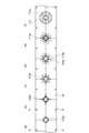
- 4 (a) to 4 (f) are plan views showing the entire punching layout.
- FIGS. 5A and 5B are plan views showing the layouts shown in FIGS. 4A and 4B in an enlarged manner.
- 6 (a) and 6 (b) are plan views showing the layouts shown in FIGS. 4 (c) and 4 (d) in an enlarged manner, respectively.
- FIGS. 7A and 7B are plan views showing the layouts shown in FIGS. 4E and 4F in an enlarged manner, respectively.
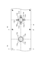
- FIG. 8 is an explanatory diagram for explaining each punching region.
- FIG. 9 is an enlarged view of the region OE shown in FIG.
- FIG. 1 is a perspective view of a laminated iron core R constituting a rotor.
- the shape of the laminated iron core R is substantially cylindrical, and the opening Ra located at the center is for mounting a shaft (not shown).
- a convex key (not shown) may be provided as a configuration for mounting the shaft on the inner peripheral surface Rb constituting the opening Ra.
- the laminated iron core R is configured by laminating a plurality of processed bodies PB (see FIG. 2).
- FIG. 2 is a plan view showing a processed body PB included in the laminated core R shown in FIG.
- the processed body PB is obtained from an electromagnetic steel plate (processed plate) by punching using a die described later.
- the processed body PB serves as a magnetic flux path between the ring-shaped annular portion 111, the plurality of magnet housing regions 112 arranged around the annular portion 111 at a predetermined interval in the circumferential direction, and the plurality of magnet housing regions 112.
- a main body portion 113 is a plan view showing a processed body PB included in the laminated core R shown in FIG.
- the processed body PB is obtained from an electromagnetic steel plate (processed plate) by punching using a die described later.
- the processed body PB serves as a magnetic flux path between the ring-shaped annular portion 111, the plurality of magnet housing regions 112 arranged around the annular
- the processed body PB includes a convex portion 114 extending from the outer peripheral surface PBc of the annular portion 111 toward the magnet housing region 112 and a connecting portion 115 extending from the outer peripheral surface PBc toward the main body portion 113.
- the connecting portion 115 connects (connects) the annular portion 111 and the main body portion 113, and the width in the circumferential direction is narrower than that of the main body portion 113.
- the main body portion 113 is formed in a substantially fan shape in plan view.
- the main body portion 113 has joint portions 113a and 113b on the radially outer side and the radially inner side.
- the laminated body R is configured by fastening the workpieces PB that overlap in the vertical direction by caulking. That is, each processed body PB has joint portions 113a and 113b that form a concave portion on the front surface and a convex portion on the back surface. Then, the upper and lower workpieces are fastened by fitting the back surface (convex portion) of the upper workpiece PB and the surface (concave portion) of the lower workpiece PB.
- the joint portions 113a and 113b are perforated instead of convex portions and concave portions.
- the laminated iron core R demonstrated that it was comprised by stacking the processed body PB and fastening these by crimping (joining part 113a, 113b), what is the method of fastening the processed body PB? Also good.
- the plurality of workpieces PB may be fastened by welding, adhesion, or a resin material. From the viewpoint of cost and work efficiency, caulking and welding have been widely used.
- a resin material or an adhesive may be employed instead of caulking or welding.
- the laminated core R may be finally obtained by removing the temporary crimp from the stacked body.
- Temporal caulking means caulking that is used to temporarily integrate a plurality of workpieces manufactured by punching and is removed in the process of manufacturing a product (laminated core).
- An outer collar 113e is provided on the radially outer side of the main body portion 113 so as to project toward the adjacent magnet housing region 112.
- the laminated core R shown in FIG. 1 is configured by laminating the above-described processed bodies PB.
- the laminated iron core R includes a cylindrical portion 11 that surrounds a shaft (rotating shaft), a plurality of magnet housing spaces 12 formed at predetermined intervals in the circumferential direction on the radially outer side of the cylindrical portion 11, and a plurality of magnet housing spaces 12. And a main body 13 serving as a magnetic flux path formed in the.
- the magnet housing space 12 is a space for housing one or a plurality of permanent magnets (for example, sintered magnets or bonded magnets such as neodymium magnets), and is a space between the side surfaces 13c of two adjacent main body portions 13. It is.
- the cylindrical portion 11, the magnet housing space 12, and the main body portion 13 are formed by laminating the annular portion 111, the magnet housing region 112, and the main body portion 113 of the processed body PB, respectively.
- an outer collar portion 13 e that protrudes from the upper surface to the lower surface of the main body portion 13 toward the adjacent magnet housing space 12 is provided.
- the size and shape of the outer collar portion 13e are determined as appropriate from the viewpoint of appropriately fixing a magnet (not shown) in the magnet housing space 12, the viewpoint of suppressing the leakage magnetic flux, and the like.
- the outer collar portion 13e is formed by laminating the outer collar 113e of the processed body PB.
- the laminated iron core R includes a convex portion 14 extending from the outer peripheral surface Rc of the cylindrical portion 11 toward the magnet housing space 12 and a connecting portion 15 extending from the outer peripheral surface Rc toward the main body portion 13.
- the convex part 14 and the connection part 15 are formed by laminating the convex part 114 and the connection part 115 of the processed body PB.
- FIG. 3 is a schematic diagram showing an example of a punching device that manufactures the processed body PB constituting the laminated core R by punching.
- the punching device 100 shown in the figure includes an uncoiler 110 to which the winding body C is mounted, a feeding device 130 for an electromagnetic steel sheet (hereinafter referred to as “working plate W”) drawn from the winding body C, and the processing plate W.
- working plate W an electromagnetic steel sheet drawn from the winding body C
- processing plate W are provided with a progressive die 140 (die) for punching and a press machine 120 for operating the progressive die 140.
- the uncoiler 110 holds the winding body C rotatably.
- the length of the work plate W constituting the wound body C is, for example, 500 to 10,000 m.
- the thickness of the work plate W constituting the wound body C may be about 0.1 to 0.5 mm. From the viewpoint of achieving better magnetic properties of the laminated core R, the thickness of the work plate W is 0.1 to 0.3 mm. It may be a degree.
- the width of the work plate W may be about 50 to 500 mm.
- the feeding device 130 has a pair of rollers 130a and 130b that sandwich the work plate W from above and below.
- the workpiece plate W is introduced into the progressive die 140 via the feeder 130.
- the progressive die 140 is for continuously performing a punching process, a bending process, a cutting process, a pushback, and the like on the work plate W.
- the laminated core R is manufactured through a process for manufacturing the processed body PB (steps (A) and (B) below) and a process for manufacturing the stacked core R from a plurality of processed bodies PB (step (C) below). Is done. More specifically, the method for manufacturing the laminated iron core R includes the following steps. (A) A step of supplying the workpiece W to the progressive die 140.
- a wound body C of electromagnetic steel sheets is prepared and attached to the uncoiler 110.
- the electromagnetic steel plate (work plate W) drawn from the wound body C is supplied to the progressive die 140 (step (A)).
- a workpiece PB in which the annular portion 111, the magnet housing region 112, and the main body portion 113 are formed is continuously manufactured by punching the workpiece W in the progressive die 140 (step (B)). . That is, in the step (B), the processed plate W is punched out by the punch of the progressive die 140 to obtain a processed body PB. In the step (B) of the present embodiment, the following steps are included in this order as a step of forming the magnet housing region 112.
- (B-0) A step of forming a preliminary removal region 112a that is a peripheral region of a region corresponding to the connecting portion 115 (a region that becomes the connecting portion 115 in the state of being the processed body PB) in the magnet housing region 112 (b -1) a step of forming a leading region 112b in the magnet housing region 112 (b-2) a step of forming a back punching region 112c in the magnet housing region 112
- FIGS. 4 (a) to 4 (f) are plan views showing the entire punching layout.
- FIGS. 5A and 5B are plan views showing the layouts shown in FIGS. 4A and 4B in an enlarged manner.
- 6 (a) and 6 (b) are plan views showing the layouts shown in FIGS. 4 (c) and 4 (d) in an enlarged manner, respectively.
- FIGS. 7A and 7B are plan views showing the layouts shown in FIGS. 4E and 4F in an enlarged manner, respectively.
- FIG. 8 is a diagram for explaining each punching area. In FIG.
- the punching region related to the preliminary punching region 112a is indicated by hatching in the magnet housing region 112
- the punching region related to the leading punching region 112b is indicated by a solid line
- the punching region related to the post punching region 112c is illustrated.
- the region is indicated by a two-dot chain line.
- FIG. 9 is an enlarged view of the region OE shown in FIG.
- the layout of the punching process is not limited to that shown in FIG. 4, and a step for balancing the press load may be added, for example, a step for forming a temporary crimp may be added. .
- Step B1 is a step of forming a preliminary punching region 112a in the work plate W in which the pilot hole P is formed (see FIGS. 4A and 5A). .
- the pilot hole P is for positioning the work plate W in the progressive die 140.
- a total of 16 preliminary removal regions 112a are formed, two in each of the magnet housing regions 112 formed in eight locations.
- a total of 16 preliminary removal regions 112a of the eight magnet housing regions 112 are formed at once.
- the preliminary removal area 112a is formed in a peripheral area of the magnet accommodating area 112 that is the area to be the connecting portion 115 of the workpiece PB (see FIG. 8).
- the preliminary extraction region 112 a is formed in a region of the magnet housing region 112 that is adjacent to the connecting portion 115 in the circumferential direction and is partitioned by the connecting portion 115 and the convex portion 114.
- the preliminary removal region 112 a may be formed not only in a region partitioned by the connecting portion 115 and the convex portion 114 but also in a region radially outside the convex portion 114.
- the preliminary punching region 112a may be made small to such an extent that the punching load applied to the connecting portion 115 does not become too large.
- Step B2 (step (b-1)) and step B3 (step (b-1)) form a pre-extracted region 112b that is formed prior to a post-extract region 112c described later in the magnet housing region 112. It is a process (see FIGS. 4B, 4C, 5B, and 6A).
- the leading-out regions 112b of the four magnet housing regions 112 that are not adjacent to each other in the circumferential direction among the eight magnet housing regions 112 formed are formed.
- the leading regions 112b of the remaining four magnet housing regions 112 are formed.
- the leading region 112b of the plurality of magnet housing regions 112 is formed in a plurality of times. That is, in the present embodiment, in the step of forming the leading region 112b, the leading regions 112b adjacent to each other in the circumferential direction are not simultaneously formed.
- a pre-extracted region 112b including the two pre-extracted regions 112a of the same magnet accommodation region 112 formed in the B1 step is formed. More specifically, in the B2 step and the B3 step, the pre-extracted region 112b is formed so that the two pre-extracted regions 112a of the same magnet housing region 112 are all included inside the pre-extracted region 112b (see FIG. 8). .
- a radially inner region of the magnet housing region 112 that is continuous with the region that becomes the annular portion 111 is formed as a pre-cut region 112b.
- the leading region 112b is a region on the inner side in the radial direction of the magnet housing region 112, and is a region having a size more than half of the entire magnet housing region 112 (see FIG. 8).
- Step B4 is a step of forming a concave portion (a convex portion when viewed from the back surface) or a perforation at a position corresponding to the joint portions 113a and 113b of the main body portion 113 in the processed body PB (FIGS. 4D and 6B). b)). That is, in step B4, when manufacturing a workpiece other than the processed body PB positioned at the lowermost part of the laminated core R, a concave portion is formed at a position corresponding to the joints 113a and 113b by bending, and the lowermost part of the laminated core R is formed. In the case of manufacturing the processed body PB located at, perforations are formed at positions corresponding to the joint portions 113a and 113b by punching.
- Step B5 is a step of forming the central region 111a by punching the inside of the annular portion 111 (see FIGS. 4E and 7A).
- Step B6 is a step of forming a post-extraction region 112c that is formed following the pre-extraction region 112b in the magnet housing region 112 (FIGS. 4F and 7B). )reference).
- the plurality of magnet housing regions 112 are formed in a lump in the back region 112c.
- a region radially outside the magnet housing region 112 with respect to the pre-extracted region 112b is formed as a post-extracted region 112c.
- step B6 the post-extract region 112c is formed so that a part of the post-extract region 112c overlaps the pre-extract region 112b. That is, the punching of the workpiece W is performed so that the portion where the punch passes in the punching region 112b in the B2 step or the B3 step and the portion where the punch passes in the punching region 112c in the B6 step overlap.
- the rear cut region 112 c is formed such that the radial inner end portion 112 y of the rear punch region 112 c is radially inward from the radially outer end portion 112 x of the front punch region 112 b.
- the leading region 112b and the trailing region 112c have an overlapping region 112z where the regions overlap each other.
- step B6 the region of the main body portion 113 is punched out simultaneously with the formation of the post-out region 112c (see the two-dot chain line in FIG. 8). Thereby, the processed body PB in which the annular portion 111, the magnet housing region 112, and the main body portion 113 are formed is obtained.
- a predetermined number of the processed bodies PB (see FIG. 2) obtained through the steps B1 to B6 are overlapped and fastened by caulking to obtain a laminated core R (step (C)).
- the manufacturing method of the laminated iron core R includes (A) a step of supplying the workpiece W to the progressive die 140 and (B) punching of the workpiece W by the progressive die 140. 111, a plurality of magnet housing regions 112 arranged at predetermined intervals in the circumferential direction around the annular portion 111, and a main body portion 113 serving as a magnetic flux path between the plurality of magnet housing regions 112 are formed. A body PB, and (C) stacking a plurality of workpieces PB and fastening them to obtain a laminated iron core R.
- the step (B) includes (b-1) a magnet housing region 112.
- the leading region 112b is formed first, and the trailing region 112c is subsequently formed. That is, the magnet housing region 112 is formed in a plurality of steps.
- region 112 is reduced.
- the residual stress in the processed body PB obtained after the punching process is reduced, and deformation of the laminated core R on which the processed body PB is stacked can be suppressed.
- the post-extracted region 112c is formed so that a part of the post-extracted region 112c overlaps the pre-extracted region 112b.
- the punching accuracy of the progressive die 140 is reduced due to the supply position accuracy of the work plate W with respect to the progressive die 140 and the assembly accuracy of the progressive die 140 being lowered, the leading punch region 112b and the trailing punch region 112c does not become a continuous punching region, and there is a possibility that generation of burrs or uncut portions may become a problem.
- leading region 112b and the trailing region 112c partially overlap each other, so that even when the punching accuracy is lowered, the leading region 112b and the trailing region 112c are easily made continuous. , Generation of burrs and the like can be suppressed.
- a radially inner region of the magnet housing region 112 that is continuous with the annular portion 111 is formed as a leading region 112b, and in the step (b-2), a magnet is formed more than the leading region 112b.
- a region on the outer side in the radial direction of the housing region 112 is formed as a post-extracting region 112c.
- a connecting portion 115 extending from the annular portion 111 toward the main body portion 113 and having a narrower circumferential width than the main body portion 113 is formed.
- the process further includes a step of forming a preliminary extraction region 112a, which is a peripheral region of the region to be the connecting portion 115, of the storage region 112 before the preliminary extraction region 112b.
- the preliminary extraction region 112a is formed.
- a pre-cut region 112b is formed.
- a connecting portion 115 having a narrow circumferential width is formed on the processed body PB from the annular portion 111 toward the main body portion 113.
- the preliminary punching region 112a which is the peripheral region of the region that becomes the connecting portion 115, is formed before the pre-extracting region 112b including the preliminary punching region 112a is formed.
- the area can be reduced (ie, the punching load can be reduced).
- the residual stress remaining in the connecting portion 115 is reduced, and deformation of the connecting portion 115 having a low strength can be suppressed.
- the pre-extracted region 112b is formed so that the pre-extracted region 112a is entirely included inside the pre-extracted region 112b.
- the preliminary removal regions 112a of the plurality of magnet housing regions 112 are collectively formed, and in the step (b-1), the leading regions 112b of the plurality of magnet housing regions 112 are divided into a plurality of times.
- the plurality of magnet housing regions 112 are formed in a lump. From the viewpoint of work efficiency, it is preferable that the formation of the magnet housing region 112 by punching is performed with as few steps as possible. However, if the area to be punched is large and the area around the area to be punched is small, the burden on the progressive die 140 becomes large when punching, so the number of punching steps is reduced while considering the burden on the progressive die 140. There is a need.
- the preliminary punching region 112a and the post punching region 112c are collectively formed, and the preliminary punching region 112b including the preliminary punching region 112a adjacent to the connecting portion 115, that is, punching is performed more than the preliminary punching region 112a.
- a region close to the connecting portion 115 having a large region and a small region is formed in a plurality of times.
- the step of forming the magnet housing region 112 has been described as including three steps: a step of forming the preliminary punching region 112a, a step of forming the leading punching region 112b, and a step of forming the post punching region 112c. It is not limited to. That is, the step of forming the magnet accommodating region 112 may include two steps, that is, the step of forming the leading punch region 112b and the step of forming the trailing punch region 112c, and includes the step of forming the preliminary punching region 112a. Alternatively, it may include a plurality of steps other than the step of forming the leading region 112b and the step of forming the trailing region 112c.
- the side 113c in the region that overlaps the rear extraction region 112c in the front extraction region 112b, the side 113c (more specifically, the overlapping region 112z shown in FIG.
- the pre-cut region 112b may be formed so that a notch is formed at a portion where the positions in the radial direction coincide with each other.
- first punch region 112b and the second punch region 112c may not overlap each other.
- the post-extracted region 112c may include the entire pre-extracted region 112b.
- first punch region 112b has been described as a radially inner region and the rear punch region 112c has been described as a radially outer region.
- the present invention is not limited thereto.
- the leading region 112b may be a radially outer region and the trailing region 112c may be a radially inner region.
- the first punch region and the second punch region may be alternately formed.
- the laminated core of the rotor which is a laminated body of processed bodies in which a plurality of magnet housing regions are arranged.
Landscapes
- Engineering & Computer Science (AREA)
- Power Engineering (AREA)
- Manufacturing & Machinery (AREA)
- Manufacture Of Motors, Generators (AREA)
- Permanent Field Magnets Of Synchronous Machinery (AREA)
- Manufacturing Cores, Coils, And Magnets (AREA)
- Iron Core Of Rotating Electric Machines (AREA)
Abstract
本開示は積層鉄心の製造方法に関する。この方法は(A)被加工板を金型に供給する工程と、(B)金型による打ち抜き加工によって、環状部と、環状部の周囲において周方向に所定の間隔で並んだ複数の磁石収容領域と、磁束の通路となる本体部分とが形成された加工体を得る工程と、(C)複数の加工体を積み重ね、これらを締結することによって積層鉄心を得る工程とを含む。(B)工程は、(b-1)磁石収容領域のうち先抜き領域を形成する工程と、(b-2)上記(b-1)工程後、磁石収容領域のうち後抜き領域を形成する工程とを含む。
Description
本開示は、回転子を構成する積層鉄心の製造方法に関する。
積層鉄心はモータの部品である。所定の形状に加工された複数の電磁鋼板(加工体)を積み重ね、これらを締結することによって積層鉄心が形成される。モータは、それぞれ積層鉄心からなる回転子(ロータ)及び固定子(ステータ)を備え、回転子にシャフトを取り付ける工程、固定子にコイルを巻きつける工程などを経て完成する。回転子を構成する積層鉄心は複数の極を有する。各極は1つ又は複数の永久磁石を有している。これらの永久磁石は積層鉄心が備える磁石収容領域(スロット)に収容されている。かかる構成の回転子を具備するモータはIPM(Interior Permanent Magnet)モータと称される。
磁石収容領域を備えた積層鉄心からなる回転子として、複数の磁石収容領域を所定の間隔で周方向に配列すると共に、隣り合う磁石収容領域間に扇状の本体部分を形成した加工体を積層した回転子が知られている(例えば特許文献1参照)。回転子を構成する積層鉄心を製造する方法として、電磁鋼板(被加工板)を順送り金型に供給する工程と、順送り金型における打抜き加工によって所定の形状の加工体を作製する工程と、作製された複数の加工体を積み重ねて積層鉄心を得る工程とを含む方法が知られている(例えば特許文献2参照)。
特許文献2に記載された打ち抜き加工によって加工体を得る場合においては、打ち抜き荷重に基づく加工体内の残留応力が問題となる。加工体内の残留応力は、積層鉄心の変形の原因となりうる。ここで、特許文献1に記載されたような、複数の磁石収容領域が周方向に複数配列されている加工体を打ち抜き加工によって得る場合には、打ち抜く領域が大きくなることによって、打ち抜き荷重が大きくなり易い。以上のことから、特許文献1に記載されたような、複数の磁石収容領域が配列された加工体により構成された積層鉄心では、打ち抜き加工に基づく残留応力を原因とした変形が生じやすい。
本開示は上記実情に鑑みてなされたものであり、複数の磁石収容領域が配列された加工体の積層体である回転子の積層鉄心において、残留応力を原因とした変形を抑制することを目的とする。
本開示の一側面に係る積層鉄心の製造方法は、(A)被加工板を金型に供給する工程と、(B)上記金型による上記被加工板の打ち抜き加工によって、環状部と、該環状部の周囲において周方向に所定の間隔で並んだ複数の磁石収容領域と、該複数の磁石収容領域間において磁束の通路となる本体部分とが形成された加工体を得る工程と、(C)複数の上記加工体を積み重ね、これらを締結することによって積層鉄心を得る工程と、を含み、上記(B)工程は、(b-1)上記磁石収容領域のうち先行して形成される先抜き領域を形成する工程と、(b-2)上記(b-1)工程後、上記磁石収容領域のうち上記先抜き領域に続いて形成される後抜き領域を形成する工程と、を含む。
当該積層鉄心の製造方法では、打ち抜き加工によって複数の磁石収容領域を形成するに際し、先行して先抜き領域が形成され、続いて後抜き領域が形成される。すなわち、磁石収容領域が複数工程に分けて形成される。これにより、磁石収容領域が一括で形成される場合と比較して、磁石収容領域の形成過程において被加工板に加わる打ち抜き荷重が低減される。このことで、打ち抜き加工後に得られた加工体における残留応力が低減され、加工体が積層された積層鉄心の変形を抑制することができる。
(b-2)工程では、先抜き領域に後抜き領域の一部が重なるように、後抜き領域を形成してもよい。金型に対する被加工板の供給位置精度や、金型の組み付け精度が低下することにより、金型の打ち抜き精度が低下した場合には、先抜き領域と後抜き領域とが連続した打ち抜き領域とならず、バリの発生や切り残しが問題となるおそれがある。この点、先抜き領域と後抜き領域とが一部重なっていることにより、打ち抜き精度が低下したような場合においても、先抜き領域と後抜き領域とを連続した領域とし易くなり、バリの発生等を抑制することができる。
(b-1)工程では、先抜き領域のうち、後抜き領域と重なる領域において、隣接する本体部分の側辺に切欠きが形成されるように、先抜き領域を形成してもよい。本体部分に切欠きが形成されることにより、先抜き領域と後抜き領域とが重なる領域をより広くすることが可能となる。これによって、打ち抜き精度が低下した場合において、先抜き領域と後抜き領域とが連続した打ち抜き領域とならないことをより確実に回避することができ、バリの発生等をより好適に抑制できる。
(b-1)工程では、環状部に連続する、磁石収容領域の半径方向内側の領域を、先抜き領域として形成し、(b-2)工程では、先抜き領域よりも磁石収容領域の半径方向外側の領域を、後抜き領域として形成してもよい。これによって、順送り金型により連続的に打ち抜き加工を行うことができる。
(B)工程では、環状部から本体部分に向かって延びた、本体部分と比べて周方向の幅が狭い連結部分を形成し、(B)工程は、(b-0)磁石収容領域のうち、連結部分となる領域の周辺領域である予備抜き領域を先抜き領域よりも先に形成する工程を更に含み、(b-1)工程では、予備抜き領域を含む先抜き領域を形成してもよい。加工体には、環状部から本体部分に向かって、周方向の幅が狭い連結部分が形成されている。このような領域が小さい部分は、強度が弱いため、打ち抜き荷重に基づく残留応力によって変形しやすい。この点、連結部分となる領域の周辺領域である予備抜き領域を、該予備抜き領域を含む先抜き領域を形成する前に形成することにより、連結部分となる領域周辺の打ち抜き領域を小さく(すなわち、打ち抜き荷重を小さく)することができる。このことにより、連結部分に残る残留応力が低減され、強度が弱い連結部分の変形を抑制することができる。
(b-1)工程では、予備抜き領域が先抜き領域の内側に全て含まれるように、先抜き領域を形成してもよい。予備抜き領域が先抜き領域に完全に含まれることにより、先抜き領域と後抜き領域とが連続した打ち抜き領域とならないことをより確実に回避することができる。これにより、バリの発生等を効果的に抑制できる。
(b-0)工程では、複数の磁石収容領域の予備抜き領域を一括で形成し、(b-1)工程では、複数の磁石収容領域の先抜き領域を複数回に分けて形成し、(b-2)工程では、複数の磁石収容領域の後抜き領域を一括で形成してもよい。作業効率性の観点から、打ち抜き加工による磁石収容領域の形成は極力少ないステップで行われることが好ましい。ただし、打ち抜く領域が大きく且つ打ち抜く箇所の周辺の領域が小さい場合には、打ち抜く際に金型にかかる負担が大きくなるため、金型の負担を考慮しながら打ち抜きのステップ数を減らす必要がある。この点、上記製造方法では、予備抜き領域及び後抜き領域を一括で形成しつつ、連結部分に近接する予備抜き領域を含む先抜き領域、すなわち、予備抜き領域よりも打ち抜き領域が大きく、且つ、領域が小さい連結部分に近接する領域を、複数回に分けて形成している。これにより、打ち抜き時に金型にかかる負担が大きくなることが明らかな工程を、複数ステップに分け、金型にかかる負担を軽減しながら、磁石収容領域の形成に係るステップを極力少なくすることができる。
本開示によれば、複数の磁石収容領域が配列された加工体の積層体である回転子の積層鉄心において、残留応力を原因とした変形を抑制することができる。
図面を参照しながら、本開示の実施形態について詳細に説明する。以下の説明において、同一要素又は同一機能を有する要素には同一符号を用いることとし、重複する説明は省略する。
<積層鉄心及び加工体>
図1は回転子を構成する積層鉄心Rの斜視図である。積層鉄心Rの形状は略円筒形であり、中央部に位置する開口Raはシャフト(不図示)を装着するためのものである。開口Raを構成する内周面Rbにはシャフトを装着するための構成として凸状キー(不図示)が設けられていてもよい。
図1は回転子を構成する積層鉄心Rの斜視図である。積層鉄心Rの形状は略円筒形であり、中央部に位置する開口Raはシャフト(不図示)を装着するためのものである。開口Raを構成する内周面Rbにはシャフトを装着するための構成として凸状キー(不図示)が設けられていてもよい。
積層鉄心Rは、複数の加工体PB(図2参照)が積層されることにより構成されている。図2は、図1に示す積層鉄心Rに含まれた加工体PBを示す平面図である。加工体PBは、後述する金型による打ち抜き加工によって、電磁鋼板(被加工板)から得られる。加工体PBは、リング状の環状部111と、環状部111の周囲において周方向に所定の間隔で並んだ複数の磁石収容領域112と、該複数の磁石収容領域112間において磁束の通路となる本体部分113と、を備えている。
加工体PBは、環状部111の外周面PBcから磁石収容領域112に向かって延びる凸部分114と、外周面PBcから本体部分113に向かって延びる連結部分115とを備えている。連結部分115は、環状部111と本体部分113とを連結(接続)しており、本体部分113よりも周方向の幅が狭くされている。
本体部分113は、平面視において略扇型状に形成されている。本体部分113は、径方向外側及び径方向内側に接合部113a,113bを有している。接合部113a,113bにおいて、上下方向で重なり合う加工体PB同士がカシメにより締結されることで、積層鉄心Rが構成されている。すなわち、各加工体PBは、表面において凹部をなし且つ裏面において凸部をなす接合部113a,113bをそれぞれ有する。そして、上側の加工体PBの裏面(凸部)と下側の加工体PBの表面(凹部)とが嵌り込むことによって、上下の加工体が締結される。複数の積層鉄心R同士が締結されないように、積層体の最下部に位置する加工体PBは、接合部113a,113bが凸部及び凹部ではなく穿孔とされている。
なお、積層鉄心Rは、加工体PBを積み重ね、これらをカシメ(接合部113a,113b)により締結することにより構成されていると説明したが、加工体PBを締結する方法はいかなるものであってもよい。例えば、溶接、接着又は樹脂材料によって複数の加工体PB同士を締結してもよい。コスト及び作業効率性の点から、カシメ及び溶接が従来から広く採用されている。一方、モータの高いトルク及び低い鉄損を優先させる場合には、カシメ又は溶接の代わりに、樹脂材料又は接着剤を採用すればよい。また、加工体PBに仮カシメを設け、これによって加工体PB同士を締結させた後、最終的に仮カシメを積層体から除去することによって積層鉄心Rを得てもよい。「仮カシメ」とは打抜き加工によって製造される複数の加工体を一時的に一体化させるのに使用され且つ製品(積層鉄心)を製造する過程において取り除かれるカシメを意味する。
本体部分113の径方向外側には、隣接する磁石収容領域112側に張り出した外つば113eが設けられている。
上述した加工体PBが積層されることにより、図1に示される積層鉄心Rが構成されている。積層鉄心Rは、シャフト(回転軸)を囲む円筒部11と、円筒部11の径方向外側において周方向に所定の間隔で形成された複数の磁石収容空間12と、複数の磁石収容空間12間に形成された磁束の通路となる本体部13と、を備えている。磁石収容空間12は、1つ又は複数の永久磁石(例えばネオジム磁石などの焼結磁石やボンド磁石)を収容するための空間であって、隣接する二つの本体部13の側面13cの間の空間である。円筒部11、磁石収容空間12、及び本体部13は、それぞれ、加工体PBの環状部111、磁石収容領域112、及び本体部分113が積層されることにより形成されている。
本体部13の径方向外側には、本体部13の上面から下面にかけて、隣接する磁石収容空間12側に張り出した外つば部13eが設けられている。外つば部13eは、磁石収容空間12内の磁石(図示せず)を適切に固定する観点、及び、漏洩磁束を小さく抑える観点等から、適宜大きさ及び形状が決定されている。外つば部13eは、加工体PBの外つば113eが積層されることにより形成されている。
積層鉄心Rは、円筒部11の外周面Rcから磁石収容空間12に向かって延びる凸部14と、外周面Rcから本体部13に向かって延びる連結部15とを備えている。凸部14及び連結部15は、加工体PBの凸部分114及び連結部分115が積層されることにより形成されている。
<打抜き装置>
図3は積層鉄心Rを構成する加工体PBを打抜き加工によって製造する打抜き装置の一例を示す概要図である。同図に示す打抜き装置100は、巻重体Cが装着されるアンコイラー110と、巻重体Cから引き出された電磁鋼板(以下「被加工板W」という。)の送り装置130と、被加工板Wに対して打抜き加工を行う順送り金型140(金型)と、順送り金型140を動作させるプレス機械120とを備える。
図3は積層鉄心Rを構成する加工体PBを打抜き加工によって製造する打抜き装置の一例を示す概要図である。同図に示す打抜き装置100は、巻重体Cが装着されるアンコイラー110と、巻重体Cから引き出された電磁鋼板(以下「被加工板W」という。)の送り装置130と、被加工板Wに対して打抜き加工を行う順送り金型140(金型)と、順送り金型140を動作させるプレス機械120とを備える。
アンコイラー110は、巻重体Cを回転自在に保持する。巻重体Cを構成する被加工板Wの長さは例えば500~10000mである。巻重体Cを構成する被加工板Wの厚さは0.1~0.5mm程度であればよく、積層鉄心Rのより優れた磁気的特性を達成する観点から、0.1~0.3mm程度であってもよい。被加工板Wの幅は50~500mm程度であればよい。
送り装置130は被加工板Wを上下から挟み込む一対のローラ130a,130bを有する。被加工板Wは、送り装置130を介して順送り金型140へと導入される。順送り金型140は、被加工板Wに対して打抜き加工、曲げ加工、切曲げ加工、プッシュバックなどを連続的に実施するためのものである。
<積層鉄心の製造方法>
次に積層鉄心Rの製造方法について説明する。積層鉄心Rは、加工体PBを製造するプロセス(下記(A)工程及び(B)工程)と、複数の加工体PBから積層鉄心Rを製造するプロセス(下記(C)工程)とを経て製造される。より具体的には、積層鉄心Rの製造方法は以下の工程を備える。
(A)被加工板Wを順送り金型140に供給する工程。
(B)順送り金型140による被加工板Wの打ち抜き加工によって、環状部111と、該環状部111の周囲において周方向に所定の間隔で並んだ複数の磁石収容領域112と、該複数の磁石収容領域112間において磁束の通路となる本体部分113とが形成された加工体PBを得る工程。
(C)複数の加工体PBを積み重ね、これらを締結することによって積層鉄心Rを得る工程。
次に積層鉄心Rの製造方法について説明する。積層鉄心Rは、加工体PBを製造するプロセス(下記(A)工程及び(B)工程)と、複数の加工体PBから積層鉄心Rを製造するプロセス(下記(C)工程)とを経て製造される。より具体的には、積層鉄心Rの製造方法は以下の工程を備える。
(A)被加工板Wを順送り金型140に供給する工程。
(B)順送り金型140による被加工板Wの打ち抜き加工によって、環状部111と、該環状部111の周囲において周方向に所定の間隔で並んだ複数の磁石収容領域112と、該複数の磁石収容領域112間において磁束の通路となる本体部分113とが形成された加工体PBを得る工程。
(C)複数の加工体PBを積み重ね、これらを締結することによって積層鉄心Rを得る工程。
まず、電磁鋼板の巻重体Cを準備し、これをアンコイラー110に装着する。巻重体Cから引き出された電磁鋼板(被加工板W)を順送り金型140に供給する((A)工程)。
順送り金型140において被加工板Wの打ち抜き加工を実施することにより、環状部111、磁石収容領域112、及び本体部分113が形成された加工体PBを連続して製造する((B)工程)。すなわち、(B)工程では、順送り金型140のパンチによって被加工板Wを打ち抜き、加工体PBを得る。本実施形態の(B)工程には、磁石収容領域112を形成する工程として以下の工程がこの順序で含まれている。
(b-0)磁石収容領域112のうち、連結部分115に相当する領域(加工体PBとなった状態において連結部分115となる領域)の周辺領域である予備抜き領域112aを形成する工程
(b-1)磁石収容領域112のうち、先抜き領域112bを形成する工程
(b-2)磁石収容領域112のうち、後抜き領域112cを形成する工程
(b-0)磁石収容領域112のうち、連結部分115に相当する領域(加工体PBとなった状態において連結部分115となる領域)の周辺領域である予備抜き領域112aを形成する工程
(b-1)磁石収容領域112のうち、先抜き領域112bを形成する工程
(b-2)磁石収容領域112のうち、後抜き領域112cを形成する工程
図4~図9を参照しながら(B)工程について説明する。図4(a)~図4(f)は打ち抜き加工のレイアウトの全体を示す平面図である。図5(a)及び図5(b)は図4(a)及び図4(b)に示すレイアウトをそれぞれ拡大して示す平面図である。図6(a)及び図6(b)は図4(c)及び図4(d)に示すレイアウトをそれぞれ拡大して示す平面図である。図7(a)及び図7(b)は図4(e)及び図4(f)に示すレイアウトをそれぞれ拡大して示す平面図である。また、図8は各打ち抜き領域を説明するための図である。図8においては、磁石収容領域112のうち、予備抜き領域112aに係る打ち抜き領域をハッチング付きで示しており、先抜き領域112bに係る打ち抜き領域を実線で示しており、後抜き領域112cに係る打ち抜き領域を2点鎖線で示している。図9は図8に示す領域OEを拡大して示す図である。なお、打抜き加工のレイアウトは図4に示すものに限定されるものではなく、プレス荷重のバランスをとるためのステップを加えてもよいし、例えば仮カシメを形成するためのステップを加えてもよい。
B1ステップ((b-0)工程)は、パイロット孔Pが形成された被加工板Wに対して予備抜き領域112aを形成する工程である(図4(a)及び図5(a)参照)。パイロット孔Pは順送り金型140における被加工板Wの位置決めを行うためのものである。B1ステップでは、予備抜き領域112aを、8か所形成される磁石収容領域112それぞれにおいて2箇所ずつ、合計16か所形成する。B1ステップでは、8か所の磁石収容領域112の、合計16か所の予備抜き領域112aを一括で形成する。
予備抜き領域112aは、磁石収容領域112のうち、加工体PBの連結部分115となる領域の周辺領域に形成される(図8参照)。例えば、予備抜き領域112aは、磁石収容領域112のうち、連結部分115と周方向において隣り合う領域であって連結部分115と凸部分114とで区画される領域に形成される。なお、図8に示されるように、予備抜き領域112aを、連結部分115と凸部分114とで区画される領域だけでなく凸部分114よりも径方向外側の領域まで形成してもよい。予備抜き領域112aは、連結部分115に加わる打ち抜き荷重が大きくなり過ぎない程度に小さくすればよい。
B2ステップ((b-1)工程)及びB3ステップ((b-1)工程)は、磁石収容領域112のうち、後述する後抜き領域112cに先行して形成される先抜き領域112bを形成する工程である(図4(b)、図4(c)、図5(b)、及び図6(a)参照)。B2ステップでは、8か所形成される磁石収容領域112のうち周方向で互いに隣り合わない4箇所の磁石収容領域112の先抜き領域112bを形成する。そして、B2ステップの後に行われるB3ステップでは、残り4箇所の磁石収容領域112の先抜き領域112bを形成する。このように、先抜き領域112bを形成する工程では、複数の磁石収容領域112の先抜き領域112bを複数回に分けて形成する。すなわち、本実施形態では、先抜き領域112bを形成する工程では、周方向において互いに隣り合う先抜き領域112bを同時に形成していない。
B2ステップ及びB3ステップでは、B1ステップにおいて形成された同一磁石収容領域112の2つの予備抜き領域112aを含む先抜き領域112bを形成する。より詳細には、B2ステップ及びB3ステップでは、同一磁石収容領域112の2つの予備抜き領域112aが先抜き領域112bの内側に全て含まれるように、先抜き領域112bを形成する(図8参照)。
B2ステップ及びB3ステップでは、環状部111となる領域に連続する、磁石収容領域112の半径方向内側の領域を、先抜き領域112bとして形成する。例えば、先抜き領域112bは、磁石収容領域112の径方向内側の領域であって、磁石収容領域112全体の半分以上の大きさの領域とされる(図8参照)。
B4ステップは、加工体PBにおける本体部分113の接合部113a,113bに相当する位置に、凹部(裏面から見ると凸部)又は穿孔を形成する工程である(図4(d)及び図6(b)参照)。すなわち、B4ステップでは、積層鉄心Rの最下部に位置する加工体PB以外を製造する場合には、曲げ加工により接合部113a,113bに相当する位置に凹部を形成し、積層鉄心Rの最下部に位置する加工体PBを製造する場合には、打ち抜き加工により接合部113a,113bに相当する位置に穿孔を形成する。
B5ステップは、環状部111の内側を打ち抜くことにより、中心領域111aを形成する工程である(図4(e)及び図7(a)参照)。
B6ステップ((b-2)工程)は、磁石収容領域112のうち、先抜き領域112bに続いて形成される後抜き領域112cを形成する工程である(図4(f)及び図7(b)参照)。B6ステップでは、複数の磁石収容領域112の後抜き領域112cを一括で形成する。具体的には、B6ステップでは、先抜き領域112bよりも磁石収容領域112の半径方向外側の領域を、後抜き領域112cとして形成する。
B6ステップでは、先抜き領域112bに後抜き領域112cの一部が重なるように、後抜き領域112cを形成する。すなわち、B2ステップ又はB3ステップの先抜き領域112bの打ち抜きにおいてパンチが通過する部分と、B6ステップの後抜き領域112cの打ち抜きにおいてパンチが通過する部分とが重なるように、被加工板Wの打ち抜きが行われる。図9に示すように、先抜き領域112bの半径方向外端部112xよりも、後抜き領域112cの半径方向内端部112yが半径方向内側となるように、後抜き領域112cを形成する。これにより、先抜き領域112bと後抜き領域112cとは、領域が互いに重なる重複領域112zを有する。
また、B6ステップでは、後抜き領域112cを形成することと同時に、本体部分113の領域を打ち抜く(図8の二点鎖線参照)。これにより、環状部111、磁石収容領域112、及び本体部分113が形成された加工体PBが得られる。
そして、上記B1~B6ステップを経て得られた加工体PB(図2参照)を所定の枚数重ね合せ、これらをカシメにより締結することによって積層鉄心Rが得られる((C)工程)。
次に、上述した積層鉄心の製造方法の作用効果について説明する。
本実施形態に係る積層鉄心Rの製造方法は、(A)被加工板Wを順送り金型140に供給する工程と、(B)順送り金型140による被加工板Wの打ち抜き加工によって、環状部111と、該環状部111の周囲において周方向に所定の間隔で並んだ複数の磁石収容領域112と、該複数の磁石収容領域112間において磁束の通路となる本体部分113とが形成された加工体PBを得る工程と、(C)複数の加工体PBを積み重ね、これらを締結することによって積層鉄心Rを得る工程と、を含み、(B)工程は、(b-1)磁石収容領域112のうち先行して形成される先抜き領域112bを形成する工程と、(b-2)上記(b-1)工程後、磁石収容領域112のうち先抜き領域112bに続いて形成される後抜き領域112cを形成する工程と、を含んでいる。
当該積層鉄心の製造方法では、打ち抜き加工によって複数の磁石収容領域112を形成するに際し、先行して先抜き領域112bが形成され、続いて後抜き領域112cが形成される。すなわち、磁石収容領域112が複数工程に分けて形成される。これにより、磁石収容領域が一括で形成される場合と比較して、磁石収容領域112の形成過程において被加工板Wに加わる打ち抜き荷重が低減される。このことで、打ち抜き加工後に得られた加工体PBにおける残留応力が低減され、加工体PBが積層された積層鉄心Rの変形を抑制することができる。
(b-2)工程では、先抜き領域112bに後抜き領域112cの一部が重なるように、後抜き領域112cを形成している。順送り金型140に対する被加工板Wの供給位置精度や、順送り金型140の組み付け精度が低下することにより、順送り金型140の打ち抜き精度が低下した場合には、先抜き領域112bと後抜き領域112cとが連続した打ち抜き領域とならず、バリの発生や切り残しが問題となるおそれがある。この点、先抜き領域112bと後抜き領域112cとが一部重なっていることにより、打ち抜き精度が低下したような場合においても、先抜き領域112bと後抜き領域112cとを連続した領域とし易くなり、バリの発生等を抑制することができる。
(b-1)工程では、環状部111に連続する、磁石収容領域112の半径方向内側の領域を、先抜き領域112bとして形成し、(b-2)工程では、先抜き領域112bよりも磁石収容領域112の半径方向外側の領域を、後抜き領域112cとして形成している。これによって、上述した環状部111、磁石収容領域112、及び本体部分113が形成された加工体PBを、順送り金型140を用いた打ち抜き加工により連続的に得ることができる。
(B)工程では、環状部111から本体部分113に向かって延びた、本体部分113と比べて周方向の幅が狭い連結部分115を形成し、(B)工程は、(b-0)磁石収容領域112のうち、連結部分115となる領域の周辺領域である予備抜き領域112aを先抜き領域112bよりも先に形成する工程を更に含み、(b-1)工程では、予備抜き領域112aを含む先抜き領域112bを形成している。加工体PBには、環状部111から本体部分113に向かって、周方向の幅が狭い連結部分115が形成されている。このような領域が小さい部分は、強度が弱いため、打ち抜き荷重に基づく残留応力によって変形しやすい。この点、連結部分115となる領域の周辺領域である予備抜き領域112aを、該予備抜き領域112aを含む先抜き領域112bを形成する前に形成することにより、連結部分115となる領域周辺の打ち抜き領域を小さく(すなわち、打ち抜き荷重を小さく)することができる。このことにより、連結部分115に残る残留応力が低減され、強度が弱い連結部分115の変形を抑制することができる。
(b-1)工程では、予備抜き領域112aが先抜き領域112bの内側に全て含まれるように、先抜き領域112bを形成している。予備抜き領域112aが先抜き領域112bに完全に含まれることにより、先抜き領域112bと後抜き領域112cとが連続した打ち抜き領域とならないことをより確実に回避することができる。これにより、バリの発生等を効果的に抑制できる。
(b-0)工程では、複数の磁石収容領域112の予備抜き領域112aを一括で形成し、(b-1)工程では、複数の磁石収容領域112の先抜き領域112bを複数回に分けて形成し、(b-2)工程では、複数の磁石収容領域112の後抜き領域112cを一括で形成している。作業効率性の観点から、打ち抜き加工による磁石収容領域112の形成は極力少ないステップで行われることが好ましい。ただし、打ち抜く領域が大きく且つ打ち抜く箇所の周辺の領域が小さい場合には、打ち抜く際に順送り金型140にかかる負担が大きくなるため、順送り金型140の負担を考慮しながら打ち抜きのステップ数を減らす必要がある。この点、上記製造方法では、予備抜き領域112a及び後抜き領域112cを一括で形成しつつ、連結部分115に近接する予備抜き領域112aを含む先抜き領域112b、すなわち、予備抜き領域112aよりも打ち抜き領域が大きく、且つ、領域が小さい連結部分115に近接する領域を、複数回に分けて形成している。これにより、打ち抜き時に順送り金型140にかかる負担が大きくなることが明らかな工程を、複数ステップに分け、順送り金型140にかかる負担を軽減しながら、磁石収容領域112の形成に係るステップを極力少なくすることができる。
以上、本開示の実施形態について説明したが本発明は上記実施形態に限定されるものではない。例えば、磁石収容領域112を形成する工程として、予備抜き領域112aを形成する工程、先抜き領域112bを形成する工程、及び後抜き領域112cを形成する工程の3工程を含むとして説明したが、これに限定されない。すなわち、磁石収容領域112を形成する工程として、先抜き領域112bを形成する工程及び後抜き領域112cを形成する工程の2工程を含んでいればよく、予備抜き領域112aを形成する工程を含んでいなくてもよいし、或いは、先抜き領域112bを形成する工程及び後抜き領域112cを形成する工程以外の複数の工程を含んでいてもよい。
また、(b-1)工程では、先抜き領域112bのうち、後抜き領域112cと重なる領域において、隣接する本体部分113の側辺113c(より具体的には、図9に示す重複領域112zと半径方向の位置が一致する部位)に切欠きが形成されるように、先抜き領域112bを形成してもよい。本体部分113に切欠きが形成されることにより、先抜き領域112bと後抜き領域112cとが重なる領域をより広くすることが可能となる。これによって、打ち抜き精度が低下した場合において、先抜き領域112bと後抜き領域112cとが連続した打ち抜き領域とならないことをより確実に回避することができ、バリの発生等をより好適に抑制できる。
また、先抜き領域112bと後抜き領域112cとは領域が重なっていなくてもよい。また、後抜き領域112cは、先抜き領域112bを全て含むものであってもよい。更に、順送り金型140によって連続的に打ち抜き加工を行う観点から、先抜き領域112bが半径方向内側の領域とされ、後抜き領域112cが半径方向外側の領域とされるとして説明したがこれに限定されず、反対に、先抜き領域112bが半径方向外側の領域とされ、後抜き領域112cが半径方向内側の領域とされてもよい。また、周方向で連続する磁石収容領域112について、先抜き領域と後抜き領域とが交互に形成されてもよい。
本開示によれば、複数の磁石収容領域が配列された加工体の積層体である回転子の積層鉄心において、残留応力を原因とした変形を抑制することができる。
11…円筒部、12…磁石収容空間、13…本体部、13c…側面、15…連結部、111…環状部、112…磁石収容領域、112a…予備抜き領域、112b…先抜き領域、112c…後抜き領域、113…本体部分、113c…側辺、115…連結部分、140…順送り金型、PB…加工体、R…積層鉄心、W…被加工板。
Claims (7)
- (A)被加工板を金型に供給する工程と、
(B)前記金型による前記被加工板の打ち抜き加工によって、環状部と、該環状部の周囲において周方向に所定の間隔で並んだ複数の磁石収容領域と、該複数の磁石収容領域間において磁束の通路となる本体部分とが形成された加工体を得る工程と、
(C)複数の前記加工体を積み重ね、これらを締結することによって積層鉄心を得る工程と、
を含み、
前記(B)工程は、
(b-1)前記磁石収容領域のうち先行して形成される先抜き領域を形成する工程と、
(b-2)前記(b-1)工程後、前記磁石収容領域のうち前記先抜き領域に続いて形成される後抜き領域を形成する工程と、
を含む、積層鉄心の製造方法。 - 前記(b-2)工程では、前記先抜き領域に前記後抜き領域の一部が重なるように、前記後抜き領域を形成する、請求項1記載の積層鉄心の製造方法。
- 前記(b-1)工程では、前記先抜き領域のうち、前記後抜き領域と重なる領域において、隣接する前記本体部分の側辺に切欠きが形成されるように、前記先抜き領域を形成する、請求項2記載の積層鉄心の製造方法。
- 前記(b-1)工程では、前記環状部に連続する、前記磁石収容領域の半径方向内側の領域を、前記先抜き領域として形成し、
前記(b-2)工程では、前記先抜き領域よりも前記磁石収容領域の半径方向外側の領域を、前記後抜き領域として形成する、請求項1~3のいずれか一項記載の積層鉄心の製造方法。 - 前記(B)工程では、前記環状部から前記本体部分に向かって延びた、前記本体部分と比べて前記周方向の幅が狭い連結部分を形成し、
前記(B)工程は、
(b-0)前記磁石収容領域のうち、前記連結部分となる領域の周辺領域である予備抜き領域を前記先抜き領域よりも先に形成する工程を更に含み、
前記(b-1)工程では、前記予備抜き領域を含む前記先抜き領域を形成する、請求項1~4のいずれか一項記載の積層鉄心の製造方法。 - 前記(b-1)工程では、前記予備抜き領域が前記先抜き領域の内側に全て含まれるように、前記先抜き領域を形成する、請求項5記載の積層鉄心の製造方法。
- 前記(b-0)工程では、複数の前記磁石収容領域の前記予備抜き領域を一括で形成し、
前記(b-1)工程では、複数の前記磁石収容領域の前記先抜き領域を複数回に分けて形成し、
前記(b-2)工程では、複数の前記磁石収容領域の前記後抜き領域を一括で形成する、請求項5又は6記載の積層鉄心の製造方法。
Priority Applications (2)
| Application Number | Priority Date | Filing Date | Title |
|---|---|---|---|
| CN201680058921.0A CN108141116B (zh) | 2015-11-05 | 2016-10-11 | 层叠铁芯的制造方法 |
| EP16861888.2A EP3373425A4 (en) | 2015-11-05 | 2016-10-11 | METHOD FOR PRODUCING A LAMINATED CORE |
Applications Claiming Priority (2)
| Application Number | Priority Date | Filing Date | Title |
|---|---|---|---|
| JP2015217507A JP6683459B2 (ja) | 2015-11-05 | 2015-11-05 | 積層鉄心の製造方法 |
| JP2015-217507 | 2015-11-05 |
Publications (1)
| Publication Number | Publication Date |
|---|---|
| WO2017077821A1 true WO2017077821A1 (ja) | 2017-05-11 |
Family
ID=58662560
Family Applications (1)
| Application Number | Title | Priority Date | Filing Date |
|---|---|---|---|
| PCT/JP2016/080134 Ceased WO2017077821A1 (ja) | 2015-11-05 | 2016-10-11 | 積層鉄心の製造方法 |
Country Status (4)
| Country | Link |
|---|---|
| EP (1) | EP3373425A4 (ja) |
| JP (1) | JP6683459B2 (ja) |
| CN (1) | CN108141116B (ja) |
| WO (1) | WO2017077821A1 (ja) |
Cited By (1)
| Publication number | Priority date | Publication date | Assignee | Title |
|---|---|---|---|---|
| WO2020017189A1 (ja) * | 2018-07-18 | 2020-01-23 | ミネベアミツミ株式会社 | モータおよびモータの製造方法 |
Families Citing this family (1)
| Publication number | Priority date | Publication date | Assignee | Title |
|---|---|---|---|---|
| WO2019172157A1 (ja) * | 2018-03-08 | 2019-09-12 | 日本電産株式会社 | 金型 |
Citations (2)
| Publication number | Priority date | Publication date | Assignee | Title |
|---|---|---|---|---|
| JP2009100535A (ja) * | 2007-10-16 | 2009-05-07 | Toyota Industries Corp | 永久磁石付き回転子における鉄心の製造方法および鉄心 |
| JP2013172491A (ja) * | 2012-02-17 | 2013-09-02 | Nippon Densan Corp | ロータコア、モータ、およびモータの製造方法 |
Family Cites Families (8)
| Publication number | Priority date | Publication date | Assignee | Title |
|---|---|---|---|---|
| JP2003211238A (ja) * | 2002-01-17 | 2003-07-29 | Matsushita Electric Ind Co Ltd | 打抜き加工法 |
| JP2007190570A (ja) * | 2006-01-17 | 2007-08-02 | Mitsui High Tec Inc | プレス送り込み方法及びその設備 |
| JP4176121B2 (ja) * | 2006-10-13 | 2008-11-05 | 株式会社三井ハイテック | 回転子積層鉄心およびその製造方法 |
| DE102009026524A1 (de) * | 2009-05-28 | 2010-12-02 | Robert Bosch Gmbh | Elektrische Maschine |
| CN102598490B (zh) * | 2010-05-18 | 2014-06-18 | 株式会社三井高科技 | 转子层叠铁心的制造方法 |
| DE102010030326A1 (de) * | 2010-06-22 | 2011-12-22 | Robert Bosch Gmbh | Befestigung von Einzelmagneten eines Maschinenteils einer elektrischen Maschine |
| JP5910036B2 (ja) * | 2011-11-30 | 2016-04-27 | 株式会社ジェイテクト | 回転機用ロータの製造方法 |
| JP6401466B2 (ja) * | 2014-03-10 | 2018-10-10 | 株式会社三井ハイテック | 積層鉄心及びその製造方法 |
-
2015
- 2015-11-05 JP JP2015217507A patent/JP6683459B2/ja active Active
-
2016
- 2016-10-11 WO PCT/JP2016/080134 patent/WO2017077821A1/ja not_active Ceased
- 2016-10-11 CN CN201680058921.0A patent/CN108141116B/zh active Active
- 2016-10-11 EP EP16861888.2A patent/EP3373425A4/en not_active Ceased
Patent Citations (2)
| Publication number | Priority date | Publication date | Assignee | Title |
|---|---|---|---|---|
| JP2009100535A (ja) * | 2007-10-16 | 2009-05-07 | Toyota Industries Corp | 永久磁石付き回転子における鉄心の製造方法および鉄心 |
| JP2013172491A (ja) * | 2012-02-17 | 2013-09-02 | Nippon Densan Corp | ロータコア、モータ、およびモータの製造方法 |
Cited By (1)
| Publication number | Priority date | Publication date | Assignee | Title |
|---|---|---|---|---|
| WO2020017189A1 (ja) * | 2018-07-18 | 2020-01-23 | ミネベアミツミ株式会社 | モータおよびモータの製造方法 |
Also Published As
| Publication number | Publication date |
|---|---|
| JP2017093067A (ja) | 2017-05-25 |
| JP6683459B2 (ja) | 2020-04-22 |
| CN108141116A (zh) | 2018-06-08 |
| EP3373425A1 (en) | 2018-09-12 |
| EP3373425A4 (en) | 2019-06-12 |
| CN108141116B (zh) | 2020-09-22 |
Similar Documents
| Publication | Publication Date | Title |
|---|---|---|
| JP6495092B2 (ja) | 分割型積層鉄心及びその製造方法 | |
| JP6683428B2 (ja) | 積層鉄心用加工体の製造方法及び積層鉄心の製造方法 | |
| CN105703565B (zh) | 层压体及其制造方法以及叠片铁芯的制造方法 | |
| JP6479392B2 (ja) | 積層鉄心及びその製造方法 | |
| JP5485926B2 (ja) | 固定子鉄心の製造方法 | |
| JP2016123157A (ja) | 回転子用積層体及びその製造方法並びに回転子の製造方法 | |
| US11482912B2 (en) | Manufacturing method of core for rotary electric machine | |
| CN106849535B (zh) | 层叠铁芯及其制造方法 | |
| JP2016152725A (ja) | 仮カシメを有する積層体及びその製造方法並びに積層鉄心の製造方法 | |
| JP2007336608A (ja) | 積層鉄心製造方法 | |
| JP6683459B2 (ja) | 積層鉄心の製造方法 | |
| JP6834899B2 (ja) | 回転電機コアの製造方法 | |
| JP7137918B2 (ja) | 積層鉄心の製造方法 | |
| JP5248972B2 (ja) | 積層鉄心の製造方法及び金型装置 | |
| JP5697640B2 (ja) | 積層鉄心の製造方法および積層鉄心製造装置 | |
| JP5964221B2 (ja) | 電機子製造方法および順送り金型装置 | |
| JP6708360B1 (ja) | ステータコアの分割コア及びこれを備えたステータ、ステータコアの分割コアの製造方法及び製造装置 | |
| JP5039499B2 (ja) | 積層固着品および積層固着品の製造方法 | |
| EP4704308A1 (en) | Method of manufacturing laminated core, laminated core, and motor | |
| JP6446302B2 (ja) | 仮カシメを有する積層体及びその製造方法並びに積層鉄心の製造方法 | |
| JP6567314B2 (ja) | 仮カシメを有する積層体及びその製造方法並びに積層鉄心の製造方法 |
Legal Events
| Date | Code | Title | Description |
|---|---|---|---|
| 121 | Ep: the epo has been informed by wipo that ep was designated in this application |
Ref document number: 16861888 Country of ref document: EP Kind code of ref document: A1 |
|
| NENP | Non-entry into the national phase |
Ref country code: DE |