WO2017078060A1 - 気泡率計測方法 - Google Patents
気泡率計測方法 Download PDFInfo
- Publication number
- WO2017078060A1 WO2017078060A1 PCT/JP2016/082559 JP2016082559W WO2017078060A1 WO 2017078060 A1 WO2017078060 A1 WO 2017078060A1 JP 2016082559 W JP2016082559 W JP 2016082559W WO 2017078060 A1 WO2017078060 A1 WO 2017078060A1
- Authority
- WO
- WIPO (PCT)
- Prior art keywords
- oil
- pressure
- sample
- bubble
- ratio
- Prior art date
- Legal status (The legal status is an assumption and is not a legal conclusion. Google has not performed a legal analysis and makes no representation as to the accuracy of the status listed.)
- Ceased
Links
Images


Classifications
-
- G—PHYSICS
- G01—MEASURING; TESTING
- G01N—INVESTIGATING OR ANALYSING MATERIALS BY DETERMINING THEIR CHEMICAL OR PHYSICAL PROPERTIES
- G01N33/00—Investigating or analysing materials by specific methods not covered by groups G01N1/00 - G01N31/00
- G01N33/26—Oils; Viscous liquids; Paints; Inks
- G01N33/28—Oils, i.e. hydrocarbon liquids
- G01N33/2888—Lubricating oil characteristics, e.g. deterioration
-
- G—PHYSICS
- G01—MEASURING; TESTING
- G01N—INVESTIGATING OR ANALYSING MATERIALS BY DETERMINING THEIR CHEMICAL OR PHYSICAL PROPERTIES
- G01N33/00—Investigating or analysing materials by specific methods not covered by groups G01N1/00 - G01N31/00
- G01N33/26—Oils; Viscous liquids; Paints; Inks
- G01N33/28—Oils, i.e. hydrocarbon liquids
- G01N33/30—Oils, i.e. hydrocarbon liquids for lubricating properties
-
- G—PHYSICS
- G01—MEASURING; TESTING
- G01N—INVESTIGATING OR ANALYSING MATERIALS BY DETERMINING THEIR CHEMICAL OR PHYSICAL PROPERTIES
- G01N7/00—Analysing materials by measuring the pressure or volume of a gas or vapour
-
- G—PHYSICS
- G01—MEASURING; TESTING
- G01N—INVESTIGATING OR ANALYSING MATERIALS BY DETERMINING THEIR CHEMICAL OR PHYSICAL PROPERTIES
- G01N33/00—Investigating or analysing materials by specific methods not covered by groups G01N1/00 - G01N31/00
- G01N33/26—Oils; Viscous liquids; Paints; Inks
- G01N33/28—Oils, i.e. hydrocarbon liquids
- G01N33/2835—Specific substances contained in the oils or fuels
- G01N33/2841—Gas in oils, e.g. hydrogen in insulating oils
Definitions
- the present invention relates to a method and an apparatus for measuring a bubble ratio, and more particularly to a method for measuring a bubble ratio contained in oil such as lubricating oil for automobiles.
- Non-Patent Document 1 As a method for measuring bubbles in the liquid, conductance method, capacitance method, wire mesh method, laser light blocking method, laser light scattering method (for example, Non-Patent Document 1), probe method (electric resistance detection method, photoelectric detection method) (for example, there are Non-Patent Document 2), image analysis method (for example, Non-Patent Document 2), resonance weight measurement method, radiography method and the like.
- Non-Patent Document 4 a method for calculating a bulk elastic modulus when bubbles are mixed into oil has been proposed.
- Non-Patent Document 3 it is considered that there is a drawback that it is impossible to detect a sufficient amount of light amount fluctuation when the bubbles are separated from the (transparent) wall surface. It is done.
- Non-Patent Document 4 there is no literature that mentions a method for calculating the bubble ratio.
- the present invention has been made in view of such a point, and an object thereof is to provide a method for measuring a bubble ratio contained in oil by a simple method.
- the method for measuring the bubble ratio of the first invention is as follows: Compressing bubble-containing oil introduced into the sealed space and measuring the bulk modulus of the oil; Referring to the bulk modulus of pre-measured bubble-free oil; And measuring the bubble rate of the oil by the step of obtaining the bubble rate based on the ratio of the measured bulk modulus and the referenced bulk modulus.
- the method for measuring the bubble ratio of the second invention is as follows: From the relationship between the product of pressure and volume change with respect to the pressure when a plurality of sample oils with known bubble ratios introduced into the sealed space are compressed to a predetermined pressure, the pressure and volume change of each sample oil at 0 kPa A step of obtaining a linear line connecting product values of quantities as a calibration line; From the relationship between the product of the pressure and the volume change with respect to the pressure when the sample oil with an unknown bubble ratio is compressed to a predetermined pressure, the value of the product of the pressure and the volume change at 0 kPa of the unknown sample oil is obtained. Step, It is composed of a step for obtaining the bubble rate of an unknown oil sample by comparing the value with a calibration line.
- the bubble ratio contained in oil can be measured by a simple method.
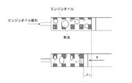
- the conceptual diagram of the bubble state engine oil after an initial state and compression is shown. It is a graph which shows the relationship between a cylinder internal pressure and volume variation. It is a graph which shows the relationship of the product of the pressure with respect to the measured pressure of each sample oil, and the air volume which behaves as gas in sample oil. It is a graph which shows the relationship of the change rate of the product of the pressure and the air volume with respect to the pressure of each sample oil.
- an oil bubble rate measuring device to which an oil bubble rate measuring method of the present invention is applied includes a cylinder (syringe) 1, a valve 3, a force sensor 4, a piezo actuator 5, and a piezo controller 6.
- oil flowing through the engine oil flow path 2 is introduced into the cylinder 1, and the piston 11 of the cylinder 1 is pressed by the piezo actuator 5 to compress the oil in the cylinder 1.
- the bubble ratio in oil is calculated by measuring the bulk modulus of oil during compression. The calculation method will be described later.
- the valve 3 opens and closes between the engine oil passage 2 and the cylinder 1.
- the force sensor 4 measures the magnitude of the force that presses the piston 11.
- the piezo controller 6 generates an electrical signal or the like for driving the piezo actuator 5 based on an instruction of a control program stored in the personal computer 7.
- the temperature sensor 8 measures the temperature of the oil in the cylinder 1. Further, the output of the force sensor 4 and the position information output from the piezo actuator 5 are transmitted to the personal computer 7, and the control program controls the piezo actuator 5 based on the information.
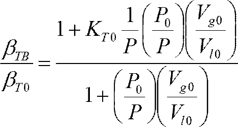
- the bulk elastic modulus K TB of the oil at the temperature T can be calculated based on Equation 1.
- P 0 is the initial cylinder pressure, and here it is atmospheric pressure.
- V 10 is the initial engine oil volume and V g0 is the initial total bubble volume.
- K T0 is the volume elastic modulus of the engine oil at the temperature T in a state where no bubbles are mixed, and here, a value measured in advance is used.
- P is the pressure in the cylinder when the piston is pushed with force F. Since the derivation process of Equation 1 is described in Non-Patent Document 4 described above, detailed description thereof is omitted.
- the initial cylinder internal pressure V 0 (the sum of V 10 and V g0 described above) is specified. it can. If the force F is pressed against the piston 11 from this state and it becomes difficult to push the piston 11 any more, it is considered that the oil bubble volume at that time is sufficiently small compared to the oil solution. Can also specify the magnitude of Vlo .
- the bulk modulus of elasticity K TB of the oil can be calculated based on the system equation stored in.
- the compression ratio of the oil can be expressed by the reciprocal of the bulk elastic coefficient of the engine oil, the engine oil in the cylinder 1 at the temperature T when the pressure P in the cylinder is gradually changed.
- the bubble ratio (void ratio) is measured by monitoring (measuring) the ratio of the compression ratio ⁇ TB and the compression ratio ⁇ TO of the engine oil in a state where no bubbles are mixed at the temperature T.
- the ratio ⁇ TB / ⁇ TO of the compression ratio can be expressed by Equation 3.
- the bubble ratio (void ratio) is specified based on which of the calibration lines (see FIG. 3) measured in advance corresponds to the compression ratio ratio / pressure relationship curve.
- the calibration line is obtained by measuring the ratio of the compressibility of oil whose bubble ratio is known in advance.
- the compression rate when the pressure P is changed by introducing a known amount of air into the oil in the cylinder 1 after gradually introducing air into the cylinder 1 and gradually displacing the piston 11.
- the ratio ⁇ TB / ⁇ TO is the calibration curve.
- the beta TO is the inverse of K TO described above, is obtained based on the bulk modulus of oil measured in advance.
- the bubble ratio of oil is measured based on the bulk modulus of oil.
- the compression of oil that is the reciprocal of the bulk modulus of oil is used. It is also within the technical scope of the present invention to obtain the bubble rate of oil by measuring the rate.
- the bubble rate of oil is measured using the cylinder 1 connected to the engine oil flow path 2 via the valve
- the ratio of V LO and V Go obtained as described above may be simply regarded as the oil bubble ratio.
- Assumption 1 The volume change when the bubble-containing engine oil is compressed is equal to the volume change of air contained as bubbles. That is, the volume of the liquid does not change.
- Assumption 2 Bubbles in oil consist of air.
- Assumption 3 Air can be regarded as an ideal gas.
- Assumption 4 Evaporation of engine oil is negligible.
- Assumption 5 The pressure in the bubble is considered to be equal to the pressure measured by the pressure sensor.
- Assumption 6 The temperature of air and engine oil in the sample are equal.
- Assumption 7 Compression of the bubbling engine oil is performed while maintaining a quasi-static state.
- a calibration line is created from a sample of a bubbled engine oil volume with a known bubble rate in the initial state at a constant temperature, and a sample of a bubbled engine oil with an unknown bubble rate is compressed between The bubble rate is derived from the pressure and volume change.
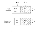
- FIG. 4 is a diagram showing a state in which air that is dispersed in the engine oil as bubbles is separated into a gas phase and a liquid phase.
- V 0 Total volume in the initial state
- V 1 Total volume in the compressed state
- P 0 Pressure in the initial state
- P 1 Pressure in the compressed state
- T Temperature (constant)
- V oil volume of engine oil
- V AIR0 total volume of the initial bubble
- Air1 total volume n all the bubbles compressed state: total material amount of the total air in the sample
- n b0 initial state
- n b1 Total amount of bubbles in compressed state
- n 0 Total amount of air dissolved in engine oil in initial state
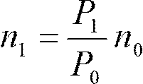
- n 1 Air dissolved in compressed engine oil
- the total substance amount ⁇ V the volume change amount.
- n 0 is expressed by Equation 8.
- Equation 9 the state equation of the bubbles when the sample is compressed to the pressure P 1 is the pressure P 0 in the initial state, the volume V 0 of the sample, the bubble rate x, in the engine oil
- Equation 9 the volume ratio a of dissolved air
- P 1 V air1 is rewritten by the sample volume and bubble ratio in the initial state and the volume change amount ⁇ V from the initial state.
- the coefficient of P 1 in the first term on the right side of Formula 10 and the other terms that do not depend on P 1 are linear expressions of the bubble ratio x, respectively.
- the bubble rate can be derived from the change.
- creation of a calibration line from a sample will be described.
- a calibration line from the sample is obtained by using a plurality of oil samples having a known bubble ratio (in this embodiment, samples having a bubble ratio of 17.3%, 23.6%, and 30.0%) in the apparatus shown in FIG. ) To conduct an experiment (hereinafter referred to as a sample test).
- FIG. 5 shows the result, and it can be confirmed that the sample with a larger initial air volume has a larger volume change amount at the same pressure.
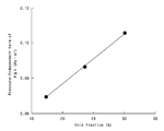
- FIG. 6 shows the results, which show that the PV air of each sample decreases with increasing pressure.
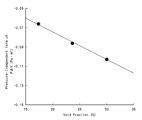
- FIG. 7 shows the relationship of the rate of change of PV air with respect to the pressure of each sample obtained by approximating each measurement data shown in FIG. 6 by a least-squares approximation as a linear expression of pressure and averaging the coefficients of the respective pressure terms. In other words, the inclination of each sample shown in FIG. 6 is shown.
- FIG. 8 shows the change in terms independent of the PV air pressure for each sample pressure determined from the sample test.
- the term which does not depend on the pressure of PV air can be expressed as a function of the void ratio x in the initial state from the second term on the right side of Expression 10.
- f (x) Ax + B A ⁇ P 0 V 0 ⁇ (1-a) B ⁇ a ⁇ P 0 V 0
- FIG. 9 shows the relationship between the product of the pressure and the volume change amount (hereinafter referred to as P ⁇ V) when compressed to the pressure P 1 from the results obtained in the sample tests shown in FIGS.
- P ⁇ V is linearly related to pressure. As in the case described above, this can be expressed as a function of the void ratio x in the initial state from the second term on the right side of Expression 10.
- g (x) Cx + D C ⁇ -P 0 V 0 ⁇ (1-a) B ⁇ -a ⁇ P 0 V 0
- FIG. 10 is a graph showing this linear function.
- FIG. 10 shows the value of P ⁇ V (the value of the y-axis intercept indicated by the thin line in FIG.
- the bubble ratio measuring method of the second embodiment is based on the relationship between the product of the pressure and the volume change amount with respect to the pressure when compressing a plurality of sample oils with known bubble ratios introduced into the sealed space to a predetermined pressure.
Landscapes
- Chemical & Material Sciences (AREA)
- Health & Medical Sciences (AREA)
- Life Sciences & Earth Sciences (AREA)
- Engineering & Computer Science (AREA)
- Biochemistry (AREA)
- Pathology (AREA)
- Immunology (AREA)
- General Physics & Mathematics (AREA)
- General Health & Medical Sciences (AREA)
- Physics & Mathematics (AREA)
- Analytical Chemistry (AREA)
- Oil, Petroleum & Natural Gas (AREA)
- Medicinal Chemistry (AREA)
- Food Science & Technology (AREA)
- General Chemical & Material Sciences (AREA)
- Chemical Kinetics & Catalysis (AREA)
- Lubrication Details And Ventilation Of Internal Combustion Engines (AREA)
- Investigating Or Analysing Materials By Optical Means (AREA)
Abstract
【課題】簡易な方法によりオイル中に含まれる気泡率を計測する。密閉空間に導入された気泡率が既知の複数のサンプルオイルを、所定圧力に圧縮した場合の圧力に対する、圧力と体積変化量の積の関係から、それぞれのサンプルオイルの0kPa時の圧力と体積変化量の積の値を結んだ一次直線を校正線とし求めるステップ、気泡率が未知のサンプルオイルを、所定圧力に圧縮した場合の圧力に対する、圧力と体積変化量の積の関係から、未知のサンプルオイルの0kPa時の圧力と体積変化量の積の値を求めするステップ、該値と校正線とを比較して未知のオイルサンプルの気泡率を得るスッテプから構成される。
Description
本発明は、気泡率の計測方法及び計測装置に関する、特に、自動車の潤滑油などのオイル中に含まれる気泡率を計測する方法等に関する。
液中の気泡を計測する方法として、コンダクタンス法、キャパシタンス法、ワイヤメッシュ法、レーザ光遮断式、レーザ光散乱式(例えば非特許文献1)、プローブ法(電気抵抗検出法、光電検出法)(例えば、非特許文献2)、画像解析法(例えば非特許文献2)、共振式重量測定法、ラジオグラフィー法などがある。
一方、油圧駆動装置の設計時においては、オイルの体積弾性係数を考慮する必要がある。しかし、オイルに気泡が混入した場合、体積弾性係数が変化するので、このことも考慮して設計を行う必要がある。そこで、オイルへの気泡混入時の体積弾性係数の算出方法が提案されている(非特許文献4)。
「ナノ粒子径分布測定装置SALD-7100」(島岡、島津評論 別刷 第63巻 第1,2号)(2006)
「単一光ファイバープローブを用いた微小気泡・液滴計測時のプレシグナル/ポストシグナル検知による接触位置判定法」(水嶋ほか、微粒化 Vol.21, No.73)(2012)
「エンジン潤滑油中の気泡挙動計測」(木村ほか、社団法人 自動車技術会 学術講演会別刷集 No.147-08)(2008)
「混入空気を考慮した油圧作動油の体積弾性係数について」(中川ほか、富山大学工学部紀要, 27: 25-30)(1976)
特開2007-064820号公報
しかし、上述した気泡計測方法は装置が複雑で高価なものが多い。また、多くの市販の測定装置では、オイル中の気泡計測に対応できないものも多い。例えば非特許文献1のレーザ光散乱式による計測装置ではオイルを吸収する青紫光が光源に選択されているので、オイル中の気泡測定に適さない。また、非特許文献2のような光プローブ式では、プローブ先端へのオイル付着状態に応じて測定誤差が生じるので、都度較正を行う必要があり、オイル中の気泡測定には適さない。
また、非特許文献3のような画像解析法に基づく方法では、気泡が(透明の)壁面から離れている場合、十分な大きさの光量変動を検出することができない、という欠点があると考えられる。
また、油圧駆動装置に係る関連技術分野においては、例えば非特許文献4に代表されるように気泡混入時のオイル特性について様々な検討がなされている。しかし、気泡率を算出する方法について言及した文献は見受けられない。
本発明は、かかる点に鑑みてなされたものであり、その目的は、簡易な方法でオイル中に含まれる気泡率を計測する方法等を提供することにある。
上記課題を解決するための本第1発明の気泡率測定方法は、
密閉空間に導入された気泡混入オイルを圧縮して該オイルの体積弾性係数を測定するステップ、
予め測定した気泡非混入のオイルの体積弾性係数を参照するステップ、
及び前記測定した体積弾性係数と前記参照した体積弾性係数の比に基づいて気泡率を得るステップとにより、オイルの気泡率を測定することを特徴とする。
密閉空間に導入された気泡混入オイルを圧縮して該オイルの体積弾性係数を測定するステップ、
予め測定した気泡非混入のオイルの体積弾性係数を参照するステップ、
及び前記測定した体積弾性係数と前記参照した体積弾性係数の比に基づいて気泡率を得るステップとにより、オイルの気泡率を測定することを特徴とする。
上記課題を解決するための本第2発明の気泡率測定方法は、
密閉空間に導入された気泡率が既知の複数のサンプルオイルを、所定圧力に圧縮した場合の圧力に対する、圧力と体積変化量の積の関係から、それぞれのサンプルオイルの0kPa時の圧力と体積変化量の積の値を結んだ一次直線を校正線とし求めるステップ、
気泡率が未知のサンプルオイルを、所定圧力に圧縮した場合の圧力に対する、圧力と体積変化量の積の関係から、未知のサンプルオイルの0kPa時の圧力と体積変化量の積の値を求めするステップ、
該値と校正線とを比較して未知のオイルサンプルの気泡率を得るスッテプから構成されている。
密閉空間に導入された気泡率が既知の複数のサンプルオイルを、所定圧力に圧縮した場合の圧力に対する、圧力と体積変化量の積の関係から、それぞれのサンプルオイルの0kPa時の圧力と体積変化量の積の値を結んだ一次直線を校正線とし求めるステップ、
気泡率が未知のサンプルオイルを、所定圧力に圧縮した場合の圧力に対する、圧力と体積変化量の積の関係から、未知のサンプルオイルの0kPa時の圧力と体積変化量の積の値を求めするステップ、
該値と校正線とを比較して未知のオイルサンプルの気泡率を得るスッテプから構成されている。
本発明によれば、簡易な方法でオイル中に含まれる気泡率を計測することができる。
以下、本発明の実施形態を図面に基づいて詳細に説明する。なお、以下の実施形態は、本質的に好ましい例示であって、本発明、その適用物、あるいはその用途の範囲を制限することを意図するものではない。
<実施形態1>
図1を参照して、本発明のオイル気泡率測定方法が適用されるオイル気泡率測定装置は、シリンダ(注射器)1と、バルブ3と、フォースセンサ4と、ピエゾアクチュエータ5と、ピエゾコントローラ6と、パーソナルコンピュータ7と、温度センサ8を有する。この測定装置では、エンジンオイル流路2を流れるオイルをシリンダ1に導入し、シリンダ1のピストン11をピエゾアクチュエータ5により押圧してシリンダ1内のオイルを圧縮する。この測定装置では、この圧縮時におけるオイルの体積弾性係数を測定することで、オイル中の気泡率を算出する。算出方法は後述する。
図1を参照して、本発明のオイル気泡率測定方法が適用されるオイル気泡率測定装置は、シリンダ(注射器)1と、バルブ3と、フォースセンサ4と、ピエゾアクチュエータ5と、ピエゾコントローラ6と、パーソナルコンピュータ7と、温度センサ8を有する。この測定装置では、エンジンオイル流路2を流れるオイルをシリンダ1に導入し、シリンダ1のピストン11をピエゾアクチュエータ5により押圧してシリンダ1内のオイルを圧縮する。この測定装置では、この圧縮時におけるオイルの体積弾性係数を測定することで、オイル中の気泡率を算出する。算出方法は後述する。
バルブ3は、エンジンオイル流路2とシリンダ1間の開閉を行う。フォースセンサ4は、ピストン11を押圧する力の大きさを測定する。ピエゾコントローラ6は、パーソナルコンピュータ7に格納した制御プログラムの指示に基づき、ピエゾアクチュエータ5を駆動するための電気信号等を生成する。温度センサ8は、シリンダ1内のオイルの温度を測定する。また、フォースセンサ4の出力、ピエゾアクチュエータ5からの位置情報出力はパーソナルコンピュータ7に伝送され、上記の制御プログラムはこれらの情報に基づいてピエゾアクチュエータ5の制御を行う。
ここで、温度Tにおけるオイルの体積弾性係数KTBは、数式1に基づいて算出することができる。

ここでは、等温変化を仮定している。P0は初期シリンダ内圧力であり、ここでは大気圧とする。Vl0は初期エンジンオイル体積であり、Vg0は初期全気泡体積である。KT0は、気泡が混入していない状態の温度Tにおけるエンジンオイルの体積弾性係数であり、ここでは予め測定されたものを用いる。Pはピストンを力Fで押した場合のシリンダ内の圧力である。なお、数式1の導出過程は上述した非特許文献4で記述されているので、その詳細説明は省略する。
また、シリンダ内の容積Vが、エンジンオイル体積Vlと、全気泡体積Vgの和であるとし、気液二相流体の圧縮/膨張は,ほとんど気相の圧縮・膨張によるとみなせば(図2参照)、数式2が成立する。
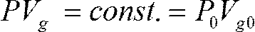
つまり、ピストン11の変位Δx(図2参照)を計測すればシリンダ1内のオイル内の気泡の体積VGの変動分が特定できるので、これにより数式1の圧力Pを算出することができる。
また、例えば、初期状態において、シリンダ1を大気圧下に配置し、ピストン11に力Fを押圧しない状態にすれば、初期シリンダ内圧力V0(前述のVl0とVg0の和)が特定できる。この状態からピストン11に力Fを押圧していき、これ以上ピストン11を押すことが困難となった場合、そのときのオイル気泡体積は、オイル溶液と比較して十分に小さいと看做すことでVloの大きさも特定できる。
つまり、少なくとも、初期圧でのピストン11の位置と、これ以上ピストン11を押すことができなくなったときのピストン11の位置情報をパーソナルコンピュータ7に伝送すれば、パーソナルコンピュータ7は、予め制御プログラム中に格納された系線式に基づいてオイルの体積弾性係数KTBを計算することができる。
また、本実施形態では、オイルの圧縮率がエンジンオイルの体積弾性係数の逆数で表現できることに着目し、シリンダ内の圧力Pを徐々に変化させた場合の温度Tにおけるシリンダ1内のエンジンオイルの圧縮率βTBと、温度Tにおける気泡が混入していない状態のエンジンオイルの圧縮率βTOの比率をモニタリング(測定)することで気泡率(ボイド率)を測定する。ここで、上記の圧縮率の比βTB/βTOは数式3で表すことができる。
つまり、ピストン11を一定の力Fで押圧することでシリンダ11内が等温変化となるようにしつつ、圧力Pを徐々に変化させ、その際の圧縮率の比を数式3に基づき算出(モニタリング)する。その結果得られた圧縮率の比と圧力の関係曲線が、予め測定した較正線(図3参照)のどれに合致するかに基づいて気泡率(ボイド率)を特定する。ここで、較正線は、予め気泡率が分かっているオイルの圧縮率の比を測定して得たものである。例えば、気泡を抜いた状態のオイルをシリンダ1に導入した後、既知量の空気をシリンダ1内のオイルに導入して、ピストン11を徐々に変位させて圧力Pを変化させたときの圧縮率の比βTB/βTOが較正曲線となる。なお、βTOは上述したKTOの逆数であり、予め測定しておいたオイルの体積弾性係数に基づいて得られるものである。
以上、本発明の実施形態について説明した。本発明の範囲はあくまでも特許請求の範囲に記載された発明に基づいて定められるものであり、上記実施形態に限定されるべきものではない。
例えば、特許請求の範囲では、オイルの体積弾性係数に基づいてオイルの気泡率を測定するものとして記載しているが、上記実施形態のように、オイルの体積弾性係数の逆数であるオイルの圧縮率を計測してオイルの気泡率を得ることも本発明の技術的範囲に属する。
また、上記実施形態では、エンジンオイル流路2にバルブ3を介して接続されたシリンダ1を用いてオイルの気泡率を測定しているが、例えば、オイルパン等に溜まったオイルをシリンダ(注射器)で抽出して、シリンダ内のオイルを封止してから、シリンダのピストンを押圧してオイル圧縮率を得て、気泡率を特定するようにしても良い。
また、簡便にオイルの気泡率を得る方法としては、単純に上記のようにして得たVLOとVGoの比率を以てオイルの気泡率とみなすようにしても良い。
<実施形態2>
実施形態2の気泡率計測方法では、
前提1:気泡混入エンジン油を圧縮した場合の体積変化は気泡として含まれている空気の体積変化に等しい。すなわち、液体の体積は変化しない。
前提2:油中気泡は空気から成る。
前提3:空気は理想気体とみなせる。
前提4:エンジン油の蒸発は無視できる。
前提5:気泡内の圧力は、圧力センサで測定した圧力と等しいとみなす。
前提6:サンプル中の空気とエンジン油の温度は等しい。
前提7:気泡混入エンジン油の圧縮は準静的状態を保ちながら行われる。
の7つの前提の基に、一定温度下で初期状態において気泡率が既知の気泡混入エンジン油体積のサンプルから校正線を作り、未知の気泡率の気泡混入エンジン油のサンプルを圧縮し、その間の圧力と体積変化から気泡率を導出するものである。
具体的には、初期状態と圧縮後の気泡混入エンジン油の概念図(図4参照)から、実施形態2で用いる測定原理の基礎式である、気体の状態方程式(数式4、数式5)物質量保存則(数式6)Henryの法則(数式7)は、以下の通りとなる。なお、図4は、気泡としてエンジンオイル中に分散して存在している空気をまとめて気相と液相に分離した状態の図にしている。


ここで、それぞれの記号は、
V0:初期状態の全体積
V1:圧縮した状態の全体積
P0:初期状態の圧力
P1:圧縮した状態の圧力
T:温度(一定)
R:気体定数
Voil:エンジン油の体積
Vair0:初期状態の気泡の総体積
Vair1:圧縮した状態の気泡の総体積
nall:サンプル中の全空気の総物質量
nb0:初期状態の気泡の総物質量
nb1:圧縮した状態の気泡の総物質量
n0:初期状態のエンジン油に溶解している空気の総物質量
n1:圧縮した状態のエンジン油に溶解している空気の総物質量
ΔV:体積変化量
を意味する。
V0:初期状態の全体積
V1:圧縮した状態の全体積
P0:初期状態の圧力
P1:圧縮した状態の圧力
T:温度(一定)
R:気体定数
Voil:エンジン油の体積
Vair0:初期状態の気泡の総体積
Vair1:圧縮した状態の気泡の総体積
nall:サンプル中の全空気の総物質量
nb0:初期状態の気泡の総物質量
nb1:圧縮した状態の気泡の総物質量
n0:初期状態のエンジン油に溶解している空気の総物質量
n1:圧縮した状態のエンジン油に溶解している空気の総物質量
ΔV:体積変化量
を意味する。
次に、気泡率とサンプルの圧力、体積の関係を考察する。サンプルの初期状態の気泡率をx(0<x<1)とするとエンジン油の体積Voilは次のように表せる。
Voil=V0-Vair0=V0-x・V0=(1-x)V0
また、初期状態のエンジン油に溶解している空気の体積割合をa(0<a<1)とすると、n0は数式8のようになる。

Voil=V0-Vair0=V0-x・V0=(1-x)V0
また、初期状態のエンジン油に溶解している空気の体積割合をa(0<a<1)とすると、n0は数式8のようになる。
数式5に数式6~数式8を代入することで、サンプルを圧力P1まで圧縮した時の気泡の状態方程式は、初期状態における圧力P0、サンプルの体積V0、気泡率x、エンジンオイル中の溶解空気の体積割合aを用いて数式9のように表すことができる。

また、P1Vair1は、初期状態におけるサンプルの体積、気泡率と初期状態からの体積変化量ΔVで書き換えると
P1Vair1=P1(Vair0-ΔV)=P1(xV0-ΔV)
で表すことができる。この式と数式9から次の数式10を導くことができる。

P1Vair1=P1(Vair0-ΔV)=P1(xV0-ΔV)
で表すことができる。この式と数式9から次の数式10を導くことができる。
数式10の右辺第1項のP1の係数及びその他のP1に依存しない項は、それぞれ気泡率xの1次式となる。これによって、一定温度下で初期状態において気泡率が既知の気泡混入エンジン油体積のサンプルから校正線を作ることで、未知の気泡率の気泡混入エンジン油のサンプルを圧縮し、その間の圧力と体積変化から気泡率を導出することができる。以下、サンプルからの校正線の作成について述べる。
サンプルからの校正線は、図1に示す装置に、複数の既知の気泡率のオイルサンプル(本実施形態においては、気泡率17.3%、23.6%、30.0%のサンプルを使用する)を用いて実験(以下、サンプル試験という)を行うことで作成する。
まず、3種のサンプルについて、圧縮と初期状態復帰とを繰り返し、10回測定した平均からシリンダ内圧力と体積変化量の関係を求める。図5は、その結果を示し、初期の空気体積が大きいサンプルほど同一圧力での体積変化量が大きいことが確認できる。
次に、シリンダ内圧力と体積変化量の関係を求めたときと同様に、圧縮と初期状態復帰とを繰り返し、10回測定した平均から圧力に対する圧力とサンプル中の気体として振る舞う空気体積との積(以下、PVairという)の関係を求める。図6は、その結果を示し、この結果から、各サンプルのPVairは、圧力の増加とともに減少することがわかる。
図7は、図6で示した各測定データを圧力の一次式として最小二乗近似し,それぞれの圧力項の係数を平均して求めた各サンプルの圧力に対するPVairの変化率の関係を示す。換言すると、図6に示す、各サンプルの傾きを示したものである。
図8は、サンプル試験から求まった各サンプルの圧力に対するPVairの圧力に依存しない項の変化を示す。また、PVairの圧力に依存しない項は、数式10の右辺第2項から初期状態のボイド率xの関数として次のように表すことができる。
f(x)=Ax+B
A≡P0V0・(1-a)
B≡a・P0V0
これより、aとP0V0を求めると
a=B/(A+B)
P0V0=A+B
となる。
サンプル試験から求めたA及びBの値はそれぞれ、A=0.284737、B=0.01671であり、初期状態のエンジン油に溶解している空気の体積割合をaは、約6vol%程度と推定される。同様に、初期状態における圧力とサンプル体積の積は(P0V0)は、約0.3Pa・m3となり、サンプル試験における初期圧力及び初期体積から求めた値と若干の誤差があるものの一致した。これにより、サンプル試験結果と計算式から求める値に相関関係を認めることができた。この初期状態のエンジン油に溶解している空気の体積割合であるaを計算により瞬時に求められることも本試験における新たな知見である。
次に、図5、図6に示すサンプル試験で得られた結果から、圧力P1に圧縮した場合の、圧力と体積変化量の積(以下、PΔVという)の関係を図9に示す。PΔVは圧力に対して直線関係であることがわかる。これは上述した場合と同様、数式10の右辺第2項から初期状態のボイド率xの関数として次のように表すことができる。
g(x)=Cx+D
C≡-P0V0・(1-a)
B≡-a・P0V0
この1次関数をグラフで表したものが図10である。図10は、各サンプルの圧力0kPaのときのPΔVの値(図9の細線で示すy軸切片の値)である。これが実施形態2の校正線となる。そして、未知の気泡率(ボイド率)であるサンプルオイルをシリンダ1に導入し、所定圧力(P)を加えたときの体積変化量(ΔV)から、図9に示す圧力と体積変化量の積のグラフ(PΔV)を作成し、0kPaのPΔVを得ることで、図10に示す校正線から瞬時にその気泡率を知ることができる。
g(x)=Cx+D
C≡-P0V0・(1-a)
B≡-a・P0V0
この1次関数をグラフで表したものが図10である。図10は、各サンプルの圧力0kPaのときのPΔVの値(図9の細線で示すy軸切片の値)である。これが実施形態2の校正線となる。そして、未知の気泡率(ボイド率)であるサンプルオイルをシリンダ1に導入し、所定圧力(P)を加えたときの体積変化量(ΔV)から、図9に示す圧力と体積変化量の積のグラフ(PΔV)を作成し、0kPaのPΔVを得ることで、図10に示す校正線から瞬時にその気泡率を知ることができる。
以上、実施形態2の気泡率計測方法は、密閉空間に導入された気泡率が既知の複数のサンプルオイルを、所定圧力に圧縮した場合の圧力に対する、圧力と体積変化量の積の関係から、それぞれのサンプルオイルの0kPa時の圧力と体積変化量の積の値を結んだ一次直線を校正線とし求めるステップ、気泡率が未知のサンプルオイルを、所定圧力に圧縮した場合の圧力に対する、圧力と体積変化量の積の関係から、未知のサンプルオイルの0kPa時の圧力と体積変化量の積の値を求めするステップ、その値と校正線(図10)とを比較して未知のオイルサンプルの気泡率を得るスッテプから構成される。
これは、図1に示す、オイル気泡率測定装置の各センサから制御装置(パーソナルコンピュータ7やマイコン)に伝送され、制御プログラムによって瞬時に計算がなされ、未知のオイルの気泡率を知ることができる。
1 シリンダ(注射器)
2 エンジンオイル流路
3 バルブ
4 フォースセンサ
5 ピエゾアクチュエータ
6 ピエゾコントローラ
7 パーソナルコンピュータ
8 温度センサ
11 ピストン
2 エンジンオイル流路
3 バルブ
4 フォースセンサ
5 ピエゾアクチュエータ
6 ピエゾコントローラ
7 パーソナルコンピュータ
8 温度センサ
11 ピストン
Claims (2)
- 密閉空間に導入された気泡混入オイルを圧縮して該オイルの体積弾性係数を測定するステップ、
予め測定した気泡非混入のオイルの体積弾性係数を参照するステップ、
及び前記測定した体積弾性係数と前記参照した体積弾性係数の比に基づいて気泡率を得るステップとを有することを特徴とするオイルの気泡率測定方法。 - 密閉空間に導入された気泡率が既知の複数のサンプルオイルを、所定圧力に圧縮した場合の圧力に対する、圧力と体積変化量の積の関係から、それぞれのサンプルオイルの0kPa時の圧力と体積変化量の積の値を結んだ一次直線を校正線とし求めるステップ、
気泡率が未知のサンプルオイルを、所定圧力に圧縮した場合の圧力に対する、圧力と体積変化量の積の関係から、未知のサンプルオイルの0kPa時の圧力と体積変化量の積の値を求めするステップ、
該値と校正線とを比較して未知のオイルサンプルの気泡率を得るスッテプから構成されるオイルの気泡率測定方法。
Priority Applications (3)
| Application Number | Priority Date | Filing Date | Title |
|---|---|---|---|
| JP2017548802A JPWO2017078060A1 (ja) | 2015-11-02 | 2016-11-02 | 気泡率計測方法 |
| EP16862120.9A EP3372983A4 (en) | 2015-11-02 | 2016-11-02 | Void fraction measurement method |
| US15/772,594 US20190094200A1 (en) | 2015-11-02 | 2016-11-02 | Method of measuring void fraction |
Applications Claiming Priority (4)
| Application Number | Priority Date | Filing Date | Title |
|---|---|---|---|
| JP2015216189 | 2015-11-02 | ||
| JP2015-216189 | 2015-11-02 | ||
| JP2016163814 | 2016-08-24 | ||
| JP2016-163814 | 2016-08-24 |
Publications (1)
| Publication Number | Publication Date |
|---|---|
| WO2017078060A1 true WO2017078060A1 (ja) | 2017-05-11 |
Family
ID=58662013
Family Applications (1)
| Application Number | Title | Priority Date | Filing Date |
|---|---|---|---|
| PCT/JP2016/082559 Ceased WO2017078060A1 (ja) | 2015-11-02 | 2016-11-02 | 気泡率計測方法 |
Country Status (4)
| Country | Link |
|---|---|
| US (1) | US20190094200A1 (ja) |
| EP (1) | EP3372983A4 (ja) |
| JP (1) | JPWO2017078060A1 (ja) |
| WO (1) | WO2017078060A1 (ja) |
Cited By (1)
| Publication number | Priority date | Publication date | Assignee | Title |
|---|---|---|---|---|
| JP2023056303A (ja) * | 2021-10-07 | 2023-04-19 | 株式会社Subaru | 気液混合流体解析方法 |
Families Citing this family (1)
| Publication number | Priority date | Publication date | Assignee | Title |
|---|---|---|---|---|
| GB2572836B (en) * | 2018-09-13 | 2020-09-02 | M-Flow Tech Ltd | Void fraction calibration method |
Citations (2)
| Publication number | Priority date | Publication date | Assignee | Title |
|---|---|---|---|---|
| JPH04230830A (ja) * | 1990-04-12 | 1992-08-19 | Afros Spa | 液体内分散気体量分析方法及びその装置 |
| US20050109078A1 (en) * | 2003-08-21 | 2005-05-26 | Appleton Papers Inc. | Real time determination of gas solubility and related parameters in manufacturing processes |
-
2016
- 2016-11-02 JP JP2017548802A patent/JPWO2017078060A1/ja active Pending
- 2016-11-02 EP EP16862120.9A patent/EP3372983A4/en not_active Ceased
- 2016-11-02 WO PCT/JP2016/082559 patent/WO2017078060A1/ja not_active Ceased
- 2016-11-02 US US15/772,594 patent/US20190094200A1/en not_active Abandoned
Patent Citations (2)
| Publication number | Priority date | Publication date | Assignee | Title |
|---|---|---|---|---|
| JPH04230830A (ja) * | 1990-04-12 | 1992-08-19 | Afros Spa | 液体内分散気体量分析方法及びその装置 |
| US20050109078A1 (en) * | 2003-08-21 | 2005-05-26 | Appleton Papers Inc. | Real time determination of gas solubility and related parameters in manufacturing processes |
Non-Patent Citations (2)
| Title |
|---|
| See also references of EP3372983A4 * |
| TAKAYUKI NAKAGAWA ET AL.: "On the bulk modulus of hydraulic fluid under entrained air condition", BULLETIN OF FACULTY OF ENGINEERING, vol. 27, 1976, pages 25 - 30, XP009506222 * |
Cited By (2)
| Publication number | Priority date | Publication date | Assignee | Title |
|---|---|---|---|---|
| JP2023056303A (ja) * | 2021-10-07 | 2023-04-19 | 株式会社Subaru | 気液混合流体解析方法 |
| JP7760318B2 (ja) | 2021-10-07 | 2025-10-27 | 株式会社Subaru | 気液混合流体解析方法 |
Also Published As
| Publication number | Publication date |
|---|---|
| EP3372983A1 (en) | 2018-09-12 |
| JPWO2017078060A1 (ja) | 2018-08-23 |
| US20190094200A1 (en) | 2019-03-28 |
| EP3372983A4 (en) | 2018-11-07 |
Similar Documents
| Publication | Publication Date | Title |
|---|---|---|
| Sochi | Slip at fluid-solid interface | |
| Hudson et al. | A microliter capillary rheometer for characterization of protein solutions | |
| US7752895B2 (en) | Method for using an alternate pressure viscometer | |
| US4890482A (en) | Method and apparatus for measuring fluid viscosity | |
| US20080127717A1 (en) | Alternative pressure viscometer device | |
| CN104101658B (zh) | 一种可以控制流速的高效液相色谱仪 | |
| CN103732607B (zh) | 用于光学测量池的气泡抑制系统 | |
| US10145819B2 (en) | Method for measuring the properties of liquid based on a quartz crystal microbalance sensor | |
| CN103674801B (zh) | 在压力脉冲衰减试验中减少不确定度的方法 | |
| US20150059446A1 (en) | Method and system for analysis of rheological properties and composition of multi-component fluids | |
| Gholizadeh et al. | Fluid bulk modulus: A literature survey | |
| Bautista et al. | A simple capillary viscometer based on the ideal gas law | |
| CN109342271B (zh) | 一种基于微量样品测量的毛细管粘度测试方法 | |
| US8844339B2 (en) | Device and method for measuring the viscosity of a fluid | |
| Olabisi et al. | Secondary and Primary Normal Stresses, Hole Error, and Reservoir Edge Effects in Cone‐and‐Plate Flow of Polymer Solutions | |
| JP2004163378A (ja) | リークテスタの漏れ流量の計算方法 | |
| Zhang et al. | Effect of gas density and surface tension on liquid film thickness in vertical upward disturbance wave flow | |
| CN104101669A (zh) | 一种用于控制系统压力脉动的高效液相色谱仪 | |
| WO2017078060A1 (ja) | 気泡率計測方法 | |
| Khamehchi et al. | Novel empirical correlations for estimation of bubble point pressure, saturated viscosity and gas solubility of crude oils | |
| Fukuta et al. | Concentration measurement of refrigerant/refrigeration oil mixture by refractive index | |
| Tohidi et al. | Viscosity and Density of Methane+ Methylcyclohexane from (323 to 423) K and Pressures to 140 MPa | |
| Sakamoto et al. | Evaluation of engine oil degradation based on viscosity and transmitted light intensity measurements | |
| Pollak et al. | Development and calibration of a high pressure high shear rate capillary rheometer | |
| Sagdeev et al. | Simultaneous measurements of the density and viscosity of 1-hexene+ 1-decene mixtures at high temperatures and high pressures |
Legal Events
| Date | Code | Title | Description |
|---|---|---|---|
| 121 | Ep: the epo has been informed by wipo that ep was designated in this application |
Ref document number: 16862120 Country of ref document: EP Kind code of ref document: A1 |
|
| ENP | Entry into the national phase |
Ref document number: 2017548802 Country of ref document: JP Kind code of ref document: A |
|
| NENP | Non-entry into the national phase |
Ref country code: DE |
|
| WWE | Wipo information: entry into national phase |
Ref document number: 2016862120 Country of ref document: EP |