WO2017081726A1 - 配管接続構造 - Google Patents
配管接続構造 Download PDFInfo
- Publication number
- WO2017081726A1 WO2017081726A1 PCT/JP2015/081491 JP2015081491W WO2017081726A1 WO 2017081726 A1 WO2017081726 A1 WO 2017081726A1 JP 2015081491 W JP2015081491 W JP 2015081491W WO 2017081726 A1 WO2017081726 A1 WO 2017081726A1
- Authority
- WO
- WIPO (PCT)
- Prior art keywords
- pipe
- high pressure
- connection
- inlet pipe
- outlet
- Prior art date
- Legal status (The legal status is an assumption and is not a legal conclusion. Google has not performed a legal analysis and makes no representation as to the accuracy of the status listed.)
- Ceased
Links
Images


Classifications
-
- F—MECHANICAL ENGINEERING; LIGHTING; HEATING; WEAPONS; BLASTING
- F02—COMBUSTION ENGINES; HOT-GAS OR COMBUSTION-PRODUCT ENGINE PLANTS
- F02B—INTERNAL-COMBUSTION PISTON ENGINES; COMBUSTION ENGINES IN GENERAL
- F02B37/00—Engines characterised by provision of pumps driven at least for part of the time by exhaust
- F02B37/12—Control of the pumps
- F02B37/18—Control of the pumps by bypassing exhaust from the inlet to the outlet of turbine or to the atmosphere
-
- F—MECHANICAL ENGINEERING; LIGHTING; HEATING; WEAPONS; BLASTING
- F02—COMBUSTION ENGINES; HOT-GAS OR COMBUSTION-PRODUCT ENGINE PLANTS
- F02B—INTERNAL-COMBUSTION PISTON ENGINES; COMBUSTION ENGINES IN GENERAL
- F02B37/00—Engines characterised by provision of pumps driven at least for part of the time by exhaust
- F02B37/013—Engines characterised by provision of pumps driven at least for part of the time by exhaust with exhaust-driven pumps arranged in series
-
- F—MECHANICAL ENGINEERING; LIGHTING; HEATING; WEAPONS; BLASTING
- F02—COMBUSTION ENGINES; HOT-GAS OR COMBUSTION-PRODUCT ENGINE PLANTS
- F02B—INTERNAL-COMBUSTION PISTON ENGINES; COMBUSTION ENGINES IN GENERAL
- F02B37/00—Engines characterised by provision of pumps driven at least for part of the time by exhaust
- F02B37/12—Control of the pumps
- F02B37/16—Control of the pumps by bypassing charging air
-
- F—MECHANICAL ENGINEERING; LIGHTING; HEATING; WEAPONS; BLASTING
- F02—COMBUSTION ENGINES; HOT-GAS OR COMBUSTION-PRODUCT ENGINE PLANTS
- F02M—SUPPLYING COMBUSTION ENGINES IN GENERAL WITH COMBUSTIBLE MIXTURES OR CONSTITUENTS THEREOF
- F02M35/00—Combustion-air cleaners, air intakes, intake silencers, or induction systems specially adapted for, or arranged on, internal-combustion engines
- F02M35/10—Air intakes; Induction systems
- F02M35/10091—Air intakes; Induction systems characterised by details of intake ducts: shapes; connections; arrangements
-
- F—MECHANICAL ENGINEERING; LIGHTING; HEATING; WEAPONS; BLASTING
- F02—COMBUSTION ENGINES; HOT-GAS OR COMBUSTION-PRODUCT ENGINE PLANTS
- F02M—SUPPLYING COMBUSTION ENGINES IN GENERAL WITH COMBUSTIBLE MIXTURES OR CONSTITUENTS THEREOF
- F02M35/00—Combustion-air cleaners, air intakes, intake silencers, or induction systems specially adapted for, or arranged on, internal-combustion engines
- F02M35/10—Air intakes; Induction systems
- F02M35/1015—Air intakes; Induction systems characterised by the engine type
- F02M35/10157—Supercharged engines
-
- F—MECHANICAL ENGINEERING; LIGHTING; HEATING; WEAPONS; BLASTING
- F16—ENGINEERING ELEMENTS AND UNITS; GENERAL MEASURES FOR PRODUCING AND MAINTAINING EFFECTIVE FUNCTIONING OF MACHINES OR INSTALLATIONS; THERMAL INSULATION IN GENERAL
- F16L—PIPES; JOINTS OR FITTINGS FOR PIPES; SUPPORTS FOR PIPES, CABLES OR PROTECTIVE TUBING; MEANS FOR THERMAL INSULATION IN GENERAL
- F16L41/00—Branching pipes; Joining pipes to walls
- F16L41/02—Branch units, e.g. made in one piece, welded, riveted
- F16L41/023—Y- pieces
-
- F—MECHANICAL ENGINEERING; LIGHTING; HEATING; WEAPONS; BLASTING
- F01—MACHINES OR ENGINES IN GENERAL; ENGINE PLANTS IN GENERAL; STEAM ENGINES
- F01N—GAS-FLOW SILENCERS OR EXHAUST APPARATUS FOR MACHINES OR ENGINES IN GENERAL; GAS-FLOW SILENCERS OR EXHAUST APPARATUS FOR INTERNAL-COMBUSTION ENGINES
- F01N2340/00—Dimensional characteristics of the exhaust system, e.g. length, diameter or volume of the exhaust apparatus; Spatial arrangements of exhaust apparatuses
-
- Y—GENERAL TAGGING OF NEW TECHNOLOGICAL DEVELOPMENTS; GENERAL TAGGING OF CROSS-SECTIONAL TECHNOLOGIES SPANNING OVER SEVERAL SECTIONS OF THE IPC; TECHNICAL SUBJECTS COVERED BY FORMER USPC CROSS-REFERENCE ART COLLECTIONS [XRACs] AND DIGESTS
- Y02—TECHNOLOGIES OR APPLICATIONS FOR MITIGATION OR ADAPTATION AGAINST CLIMATE CHANGE
- Y02T—CLIMATE CHANGE MITIGATION TECHNOLOGIES RELATED TO TRANSPORTATION
- Y02T10/00—Road transport of goods or passengers
- Y02T10/10—Internal combustion engine [ICE] based vehicles
- Y02T10/12—Improving ICE efficiencies
Definitions
- the present disclosure relates to a pipe connection structure in which two inlet pipes and one outlet pipe are connected via a connection pipe.
- a supercharger for supplying more intake air to the engine of a vehicle as having a pipe connection structure in which two inlet pipes and one outlet pipe are connected via a connecting pipe. Piping structure is known.
- Patent Document 1 two turbochargers, a high pressure turbine bypass passage bypassing the turbine of the turbocharger provided upstream, an exhaust control valve opening and closing the bypass passage, and an upstream side are provided.
- a high pressure compressor bypass passage bypassing the compressor of the turbocharger and an intake bypass valve opening and closing the bypass passage are configured to change the driven turbocharger according to the operating condition.
- a high pressure side outlet pipe (inlet pipe) for discharging exhaust gas is connected to a turbine of a supercharger provided on the upstream side, and a high pressure side outlet pipe (inlet pipe) and a high pressure turbine bypass passage (inlet pipe) are high pressure turbines. It communicates with the outlet side arrangement passage (outlet pipe).
- the high pressure side outlet pipe (inlet pipe) and the high pressure turbine bypass passage (inlet pipe) are separated for convenience of the layout in the engine room of the vehicle.
- the high-pressure turbine outlet side arrangement passage (outlet pipe) may be arranged at an offset position with respect to the center of the. In such a case, the inlet pipe far from the high pressure turbine outlet side arrangement passage (outlet pipe) needs to be connected to the outlet pipe via the connecting pipe.
- the exhaust pipe discharged from the inlet pipe on the side far from the outlet pipe is diverted by the connecting pipe in a direction close to perpendicular to the direction of discharge from the inlet pipe, and the inlet pipe and outlet pipe on the side closer to the outlet pipe If a space is formed between them, there is a possibility that a swirling flow may occur which flows toward the outlet pipe while the exhaust gas flowing in the connecting pipe swirls. When this swirling flow occurs, the pressure loss of the piping increases, and there is a possibility that the turbine performance of the turbocharger disposed downstream may be reduced.
- At least one embodiment of the present invention is an invention made under the circumstances of such prior art, in which the purpose is to connect two inlet pipes to an outlet pipe via a connecting pipe.
- the purpose is to connect two inlet pipes to an outlet pipe via a connecting pipe.
- it is possible to provide a piping connection structure that can be introduced into the outlet pipe by suppressing the possibility that the gas flowing in the connection pipe will be a swirling flow.
- a pipe connection structure is Two inlet pipes through which gas can flow, A connecting pipe in which the outlet ends of the two inlet pipes are connected at intervals; The two inlet pipes are connected to the connecting pipe opposite to the side connected to the connecting pipe, and an outlet pipe can be communicated with the two inlet pipes via a space in the connecting pipe.
- the two inlet pipes are one side inlet pipe located on one side in the connecting pipe width direction with respect to the center between connection positions of the two inlet pipes to the connecting pipe, and the other side located on the other side
- an inlet pipe The outlet pipe is connected to a position offset to the other side in the connecting pipe width direction
- the space in the connection pipe has an axial length equal to or greater than an imaginary diameter D defined by the following equation (1) along the axial center direction of the one-side inlet pipe. Connection structure.
- the space in the connecting pipe has an axial length equal to or greater than the virtual diameter D defined by the following equation (1) It is configured to have.
- D ⁇ (4A / ⁇ ) (However, A is the cross-sectional area of the one-side inlet pipe, and ⁇ is the circle ratio.)
- A represents the cross-sectional area of the one-side inlet pipe, and the cross-sectional shape of the one-side inlet pipe does not matter.
- the cross-sectional shape of the one-side inlet pipe includes any of circular, rectangular, combinations thereof, and the like. Further, by setting the axial length of the space portion in the connecting portion to the virtual diameter D or more, the straightness of the gas discharged from the one-side inlet pipe can be strengthened. Therefore, it is possible to realize a pipe connection structure which can be introduced into the outlet pipe by suppressing the possibility of the gas flowing in the connection pipe becoming a swirling flow.
- a pipe connection structure according to at least one embodiment of the present invention, Two inlet pipes through which gas can flow, A connecting pipe in which the outlet ends of the two inlet pipes are connected at intervals;
- the two inlet pipes are connected to the connecting pipe opposite to the side connected to the connecting pipe, and an outlet pipe can be communicated with the two inlet pipes via a space in the connecting pipe.
- the two inlet pipes are one side inlet pipe located on one side in the connecting pipe width direction with respect to the center between connection positions of the two inlet pipes to the connecting pipe, and the other side located on the other side And an inlet pipe,
- the outlet pipe is connected to a position offset to the other side in the connecting pipe width direction,
- the axial length of the space portion in the connection pipe along the axial direction of the one side inlet pipe is the connection position where the one side inlet pipe is connected to the connection pipe, and the outlet pipe is the connection pipe And 50% or more of the length along the axial direction of the one-side inlet pipe between the connection position connected to the.
- the axial length of the one side inlet pipe in the space along the axial direction (hereinafter, “straight line length L1”) is such that the one side inlet pipe is a connecting pipe
- the length along the axial direction of the one-side inlet pipe between the connected connection position and the connected position where the outlet pipe is connected to the connection pipe (hereinafter referred to as “straight portion length L2”) It has 50% or more.
- the intention of the invention according to claim 2 is to make the straight portion length L1 as long as possible under the restriction of the straight portion length L2.
- the straight portion length L1 is too short, the flow of the gas discharged from the one side inlet pipe is immediately turned to the other side inlet pipe side, and a swirling flow occurs.
- the piping connection structure as described in said (2) may be comprised so that it may also have the piping connection structure as described in said (1).
- the space in the connecting pipe is configured to form a curved portion that protrudes into the portion and curves in an arc shape.
- the top inner wall on the side to which the outlet pipe is connected and between the outlet pipe and the one-side inlet pipe
- the top inner wall located is formed with a curved portion that protrudes into the space and curves in an arc shape.
- the outlet pipe is disposed at a position offset to one side in the connecting pipe width direction with respect to the two one-side inlet pipes and the other-side inlet pipe. Then, the gas discharged from the inlet pipe flows in the space and flows into the outlet pipe in a state where the straightness is enhanced. For this reason, the deviation of the flow of gas tends to occur by the amount by which the outlet pipe is disposed offset to one side in the connecting pipe width direction.
- the curved inner wall is the top inner wall on the side to which the outlet pipe is connected and is located between the outlet pipe and the one-side inlet pipe It is provided.
- the curved portion weakens the rectilinearity of the gas and may cause a swirling flow, but the swirling flow is likely to be generated near the inlet of the connecting pipe where the space is expanded and the space is narrow near the outlet of the connecting pipe Therefore, the generation of swirling flow is slight. For this reason, by providing a curved portion that projects into the space on the top inner wall located between the outlet pipe and the one-side inlet pipe, there is a possibility that some swirling flow may occur, but more than that Can be done reliably.
- the curved portion is configured such that an inner wall positioned on the outlet pipe side among the inner walls forming the curved portion is in contact with the inner wall on the curved portion side of the outlet pipe.
- the bending portion is formed at a position where the inner wall located on the outlet pipe side among the inner walls forming the bending portion contacts the inner wall on the bending portion side of the outlet pipe.
- the curved portion is configured to extend in a direction substantially orthogonal to the traveling direction of the gas flowing from the one side inlet pipe to the outlet pipe side via the space portion in the connection pipe.
- the curved portion extends in a direction substantially orthogonal to the traveling direction of the gas flowing from the one side inlet pipe to the outlet pipe side via the space portion in the connecting pipe ing. Therefore, when the gas passes through the curved portion, the flow of the gas can be sent in a direction substantially orthogonal to the extending direction of the curved portion, and the air flow biased to one side of the outlet pipe is It can be extended to the other side. Therefore, it is possible to increase the accuracy of removal of flow rate distortion of the gas flowing into the outlet pipe.
- the one-side inlet pipe is applied to a high pressure side turbine lead-out passage for leading exhaust gas discharged from a turbine of the high pressure turbo in a two-stage supercharging system in which a low pressure turbo and a high pressure turbo are connected in series;
- the other side inlet pipe is applied to a high pressure side turbine bypass passage bypassing the turbine of the high pressure turbo.
- the outlet pipe is applied to a low pressure side turbine introduction passage for introducing exhaust gas into the low pressure turbo turbine,
- the high pressure side turbine lead-out passage, the high pressure side turbine bypass passage, and the low pressure side turbine introduction passage are connected to the connection pipe.
- the one-side inlet pipe discharges the exhaust gas discharged from the high pressure turbo turbine in the two-stage supercharging system in which the low pressure turbo and the high pressure turbo are connected in series.
- the side turbine outlet passage Applied to the side turbine outlet passage.
- the other side inlet pipe is applied to the high pressure side turbine bypass passage bypassing the high pressure turbo turbine.
- the outlet pipe is applied to the low pressure side turbine introduction passage which introduces the exhaust gas to the low pressure turbo turbine.
- the high pressure side turbine lead-out passage, the high pressure side turbine bypass passage, and the low pressure side turbine introduction passage are connected to the connection pipe.
- the pipe connection structure capable of suppressing the generation of the swirling flow in the flow path connected to the turbine side of the high pressure turbo in the two-stage supercharging system, the exhaust gas becomes the swirling flow and is supplied to the low pressure turbo You can control the situation. For this reason, the performance deterioration of the low pressure turbo can be suppressed.
- the one-side inlet pipe is a two-stage in which a low pressure turbo and a high pressure turbo are connected in series. It is applied to a high pressure side compressor lead passage for leading intake air from the high pressure turbo compressor in a supercharging system, and the other side inlet pipe is applied to a high pressure side compressor bypass passage bypassing the high pressure turbo compressor, the outlet pipe Is applied to a charge introduction passage for introducing intake air into the engine of the two-stage supercharging system, and a high pressure side compressor lead passage, the high pressure side compressor bypass passage, and the charge introduction passage are connected to the connection pipe. Configured to
- the one side inlet pipe is a high pressure side compressor lead-out for drawing the intake air from the high pressure turbo compressor in the two-stage supercharging system in which the low pressure turbo and the high pressure turbo are connected in series. It applies to the passage.
- the other side inlet pipe is applied to the high pressure side compressor bypass passage which bypasses the high pressure turbo compressor.
- the outlet pipe is then applied to a charge introduction passage for introducing intake air to the engine of the two-stage supercharging system.
- the connection pipe is configured to be connected to the high pressure side compressor lead-out passage, the high pressure side compressor bypass passage, and the air supply introduction passage.
- the pipe connection structure capable of suppressing the generation of the swirling flow in the flow path connected to the compressor side of the high pressure turbo in the two-stage supercharging system, the exhaust gas is supplied as a swirling flow to the engine Can be suppressed.
- the piping connection structure concerning one Embodiment of this invention WHEREIN It is sectional drawing which showed the cross section along the axial center direction of the inlet pipe. It is sectional drawing of the piping connection structure which made the comparison object comparatively short the length of the space part in a connecting pipe with respect to the piping connection structure of this invention. It is sectional drawing of the piping connection structure of comparison object provided with the connecting pipe with the flow path inclined with respect to the inlet pipe. It is sectional drawing of the piping connection structure of comparison object provided with the connecting pipe which had the flow path which inclined with respect to the inlet pipe with respect to the piping connection structure of this invention. It is a top view of the connecting pipe which is a part of piping connection structure of the present invention.
- the piping connection structure concerning one Embodiment of this invention WHEREIN It is sectional drawing of the piping connection structure which provided the curved part in the near side of the outlet pipe of a connection pipe
- a representation representing a relative or absolute arrangement such as “in a direction”, “along a direction”, “parallel”, “orthogonal”, “center”, “concentric” or “coaxial” is strictly Not only does it represent such an arrangement, but also represents a state of relative displacement with an angle or distance that allows the same function to be obtained.
- expressions representing shapes such as quadrilateral shapes and cylindrical shapes not only represent shapes such as rectangular shapes and cylindrical shapes in a geometrically strict sense, but also uneven portions and chamfers within the range where the same effect can be obtained.
- the shape including a part etc. shall also be expressed.
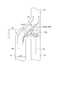
- FIG. 1 is a cross-sectional view showing a cross section along an axial center direction of an inlet pipe in a pipe connection structure according to an embodiment of the present invention
- FIG. 2 is a cross-sectional view of the pipe connection structure of the present invention
- FIG. 3 is a cross-sectional view of a pipe connection structure for comparison, in which the length of the space in the connection pipe is relatively short
- FIG. 3 is a pipe for comparison that includes a connection pipe having a flow path inclined with respect to the inlet pipe.
- FIG. 4 is a cross-sectional view of a connection structure
- FIG. 1 is a cross-sectional view showing a cross section along an axial center direction of an inlet pipe in a pipe connection structure according to an embodiment of the present invention
- FIG. 2 is a cross-sectional view of the pipe connection structure of the present invention
- FIG. 3 is a cross-sectional view of a pipe connection structure for comparison, in which the length of the space in the connection pipe is relatively short
- FIG. 3
- FIG. 4 is a cross-sectional view of a pipe connection structure to be compared that includes a connection pipe having a flow path inclined with respect to an inlet pipe in the pipe connection structure of the present invention
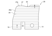
- FIG. 5A is a plan view of a connecting pipe which is a part of the pipe connecting structure of the present invention
- FIG. 5B is a side view of the connecting pipe
- FIG. 8 is a straight line of the connecting pipe in the pipe connecting structure of the present invention. It is sectional drawing of the connecting pipe for demonstrating the length of a part.
- the pipe connection structure according to the embodiment of the present invention is not particularly limited, but is applied to, for example, a two-stage turbo pipe structure mounted on an automobile engine or the like.
- two one-side inlet pipes 10 and two other-side inlet pipes 13 through which gas can flow and two one-side inlet pipes 10 and the other-side inlet A connecting pipe 20 to which the outlet ends 10a and 13a of the pipes 13 are connected with a gap, and a side where two one-side inlet pipes 10 and the other-side inlet pipe 13 are connected to the connecting pipe 20
- the outlet pipe 40 comprises an outlet pipe 40 connected to the opposite connection pipe 20 and capable of communicating with the two one-side inlet pipes 10 and the other-side inlet pipe 13 via the space 21 in the connection pipe 20.
- the space 21 in the connecting pipe 20 communicating with the one side inlet pipe 10 extends along the axial direction of the one side inlet pipe 10, and the axial length L1 of the space 21 is smaller than that of the one side inlet pipe. It is formed to have an axial length equal to or greater than the imaginary diameter D defined by the equation (1).
- the cross section of the outlet end 10a of the one side inlet pipe 10 has a shape including an arc and a straight line (see FIG. 5A), and the cross section of the other side inlet pipe 13 is formed in a circular shape (See FIG. 5A).
- the cross-sectional areas of the two one-side inlet pipes 10 and the other-side inlet pipes 13 may or may not be the same.
- the outlet end portions 10 a and 13 a of the two one-side inlet pipes 10 and the other-side inlet pipe 13 are connected to the bottom 23 of the connecting pipe 20.
- the outlet end portions 10a and 13a of the two one-side inlet pipes 10 and the other-side inlet pipes 13 are arranged at intervals such that their respective axis centers 10b and 13b are parallel. Gas can flow through the two one-side inlet pipes 10 and the other-side inlet pipe 13, and gas can selectively flow only through one of the two one-side inlet pipes 10 and the other-side inlet pipe 13. Is configured.
- the outlet pipe 40 is formed in a tubular shape having a rectangular cross-sectional shape (see FIG. 5A).
- the cross-sectional shape of the outlet pipe 40 is not limited to a rectangular shape, and may be a circular shape.
- the cross-sectional area of the outlet pipe 40 may have a size different from the cross-sectional area of the one-side inlet pipe 10, 13.
- the outlet pipe 40 is connected to a position offset to one side with respect to the center K between the connection positions of the two one-side inlet pipes 10 and the other-side inlet pipe 13 to the connecting pipe 20 in the illustrated embodiment.
- the outlet pipe 40 is disposed above the other side inlet pipe 13 on the right side in the left-right direction of the two one side inlet pipes 10 and the other side inlet pipe 13. Therefore, the gas discharged from the other side inlet pipe 13 can flow straight through the connection pipe 20 and can flow into the outlet pipe 40.
- the connecting tube 20 is formed in a box shape having a hollow inside, and has a flat bottom 23 and a trunk 25 extending upward from the periphery of the bottom 23. , And a top 27 that covers the upper end of the body 25.
- a hole 23a including an arc and a straight line in cross section is formed on one side (left side in the left-right direction) of the bottom 23 in the longitudinal direction, and on the other side (right side in the left-right direction)
- a circular hole 23 b is formed.
- the one side inlet pipe 10 and the other side inlet pipe 13 corresponding to the holes 23a and 23b are connected.
- the four corners of the body 25 are curved, and the whole body 25 is formed to incline in the inward direction of the body as it extends upward.
- the left side in the left-right direction of the top 27 is formed with a projecting portion 27 a that curves and protrudes upward, and the right side in the left-right direction of the top 27 is formed with a rectangular hole 27 b communicating with the outlet pipe 40.
- FIG. 2 shows a cross-sectional view of a pipe connection structure to be compared, showing a case where the vertical length L1 of the body 25 is smaller than the virtual diameter D of the one-side inlet pipe 10.
- the circumferential component ds in the flow direction d of the gas increases with the flow of the gas, and a swirling flow tends to occur.
- the connecting pipe 20 ' is formed such that the axial length L1 of the space 21' is substantially the same as the virtual diameter D of the one side inlet pipe 10, the connection extending to the outlet pipe side
- the inclination angle of the pipe 20 ′ is about 45 °, and the axial component dv of the flow direction d of the gas flowing toward the outlet pipe 40 and the circumferential component ds orthogonal to this can be equalized.
- the connection is made.
- a pressure gradient is generated such that the pressure Pa inside the gas turning direction before the gas flowing inside the pipe 20 flows into the outlet pipe 40 is larger than the pressure Pb outside the turning direction (flow curvature theorem). Therefore, among the gas discharged from the one-side inlet pipe 10, the gas flowing on the other-side inlet pipe 13 side has a space 21a between the other-side inlet pipe 13 and the outlet pipe 40. Due to the directional component ds, there is a risk that the gas will flow upward while swirling, and the pressure loss will increase.
- the axial length L1 of the space portion 21 is made equal to or more than the virtual diameter D of the one side inlet pipe 10, as shown in FIG. 1, it is discharged from the outlet side end 10a of the one side inlet pipe 10 and moves straight.
- the flow path length L1 of the flowing gas can be made longer. For this reason, the straightness of the gas discharged from the one side inlet pipe 10 can be strengthened. Therefore, it is possible to suppress the possibility that the gas flowing in the connection pipe 20 becomes a swirling flow.
- the axial length L1 of the space 21 is a connection position P1 at which the one-side inlet pipe 10 is connected to the connection pipe 20 and a connection position P2 at which the outlet pipe 40 is connected to the connection pipe 20. And 50% or more of the length L2 along the axial direction of the one-side inlet pipe 10 between them. That is, the axial length L1 of the space 21 is configured such that the axial length L1 is as long as possible under the restriction of the length L2. In the present embodiment, the axial length L1 of the space 21 is 73% of the length L2.
- the flow path length L1 of the gas flowing straight from the outlet of the one-side inlet pipe 10 is elongated
- the length of the flow passage flowing toward the outlet pipe 40 can be shortened by inclining from the straightly extending flow passage.
- a pressure gradient in which the pressure Ps inside the gas turning direction becomes larger than the pressure Pb outside the turning direction is generated. Since the length of the flow path flowing toward the outlet pipe side is inclined from the flow path, the range in which the pressure gradient acts can be shortened. Therefore, the increase in the circumferential component of the gas direction due to the action of the pressure gradient can be suppressed. Therefore, the possibility of the gas flowing in the connection pipe 20 becoming a swirling flow can be further suppressed.
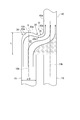
- FIG. 6 is a cross-sectional view of the pipe connection structure in which the bending portion 30 is provided on the front side of the outlet pipe 40 of the connection pipe 20 in the pipe connection structure according to the embodiment of the present invention.
- FIG. 5A, FIG. 5B, and FIG. 6 it is the top inner wall 21a1 on the side to which the outlet pipe 40 is connected among the inner walls 21a forming the space 21 in the connection pipe 20.
- a curved portion 30 which protrudes into the space 21 and is curved in an arc shape is formed.
- the bending portion 30 is formed to have a circular arc drawn by a radius R around a fulcrum O provided on the outside of the connecting pipe 20.
- the gas discharged from the one-side inlet pipe 10 flows in the space 21 and flows into the outlet pipe 40 in a state in which the straightness is enhanced.
- the gas is offset by the offset pipe 40 with respect to the one-side inlet pipe 10 Flow bias is likely to occur. That is, the gas tends to be biased to the one side inlet pipe 10 side of the outlet pipe 40.
- the curved portion 30 is provided on the top inner wall 20a1 of the connection pipe 20 which forms a flow path before the gas flows into the outlet pipe 40. Due to this curved portion 30, there is a possibility that the straightness of the gas is weakened to generate a swirling flow.
- the swirling flow is likely to occur near the inlet of the connecting pipe 20 where the space 21 is expanded, and the space 21 narrows near the outlet of the connecting pipe 20, so that the swirling flow is slight. Therefore, by providing the curved portion 30 projecting into the space 21 on the top inner wall 20a1 located between the outlet pipe 40 and the one-side inlet pipe 10, there is a possibility that some swirling flow may occur. It is possible to reliably eliminate the drift more than that.
- the bending portion 30 is configured to be formed at a position where the inner wall 30b located on the outlet pipe 40 side among the inner walls 30b forming the bending portion 30 contacts the inner wall 40a on the bending portion side of the outlet pipe 40 There is. For this reason, since the curved portion 30 is formed at a position close to the outlet pipe 40, it is possible to suppress the generation of the swirling flow and to eliminate the partial flow of the gas flowing into the outlet pipe 40.
- the bending portion 30 is substantially orthogonal to the traveling direction of the gas flowing from the one side inlet pipe 10 on the side away from the outlet pipe 40 to the outlet pipe 40 via the space 21 in the connecting pipe 20. Extended (see FIG. 5A).
- the gas when the gas passes through the curved portion 30, the gas can flow uniformly in the direction substantially orthogonal to the traveling direction of the gas.
- the gas flow can be sent in a direction substantially orthogonal to the extending direction of the curved portion 30, and the air flow biased to one side of the outlet pipe 40 is an outlet pipe 40 Can be extended to the other side of the Therefore, the accuracy of removal of flow rate distortion of the gas flowing into the outlet pipe 40 can be improved.
- FIG. 7 is a schematic configuration view of a two-stage turbo piping provided with the pipe connection structure of the present invention.
- the high pressure turbo 45 and the low pressure turbo 50 are connected in series, and the high pressure turbo 45 is disposed upstream of the low pressure turbo 50 in the exhaust path 53.
- Exhaust gas discharged from the cylinder 61 of the engine 60 gathers in the exhaust manifold 62 and passes through the exhaust path 53 through the high pressure turbine 45a of the high pressure turbo 45 and a portion thereof through the high pressure turbine bypass passage 55
- the low pressure turbine 50 a of the low pressure turbo 50 is fed through the passage 56.
- An exhaust gas control valve 57 is provided in the high pressure side turbine bypass passage 55.
- one side inlet pipe 10 of the two one side inlet pipes 10 and the other side inlet pipe 13 described above is a high pressure in a two-stage supercharging system in which a low pressure turbo 50 and a high pressure turbo 45 are connected in series.
- the present invention is applied to the high pressure side turbine lead-out passage 58 for leading the exhaust gas discharged from the high pressure turbine 45a of the turbo 45, and the other side inlet pipe 13 is applied to the high pressure side turbine bypass passage 55 for bypassing the high pressure turbine 45a.
- the outlet pipe 40 is applied to the low pressure side turbine introduction passage 56 for introducing the exhaust gas into the low pressure turbine 50 a of the low pressure turbo 50.
- the high pressure side turbine lead-out passage 58, the high pressure side turbine bypass passage 55, and the low pressure side turbine introduction passage 56 are connected to the connection pipe 20.
- the exhaust gas control valve 57 regulates the relationship between the amount of exhaust gas of the high pressure turbo 45 and the amount of exhaust gas sent to the low pressure turbine 50 a of the low pressure turbo 50 by bypassing the high pressure turbo 45 by controlling the opening degree. It is That is, to the low pressure turbine 50 a of the low pressure turbo 50, the exhaust from the high pressure turbine 45 a of the high pressure turbo 45 passes through the high pressure side turbine lead-out passage 58, and the flow rate is adjusted by the exhaust gas control valve 57 and flows through the high pressure side turbine bypass passage 55 The exhaust gases are mixed in the connecting pipe 20 and fed through the low pressure side turbine introduction passage 56.
- the low pressure compressor 50b is coaxially driven by the low pressure turbine 50a to pressurize the air from the air cooler 69 and pass it through the low pressure side compressor lead passage 70 and the high pressure side compressor introduction passage 71. It supplies to the compressor 45b.
- the high pressure compressor 45b is coaxially driven by the high pressure turbine 45a and supplied from the air supply manifold 75 to the cylinder 61 of the engine 60 through the high pressure side compressor lead-out passage 72, the intercooler 73, and the air supply introduction passage 74. Ru.
- a high pressure compressor bypass passage 76 communicating with the high pressure compressor introduction passage 71 and the high pressure compressor discharge passage 72 and bypassing the high pressure compressor 45 b is provided.
- a compressor bypass valve device 77 is provided in the high pressure side compressor bypass passage 76. The compressor bypass valve device 77 controls the amount of air bypassing the high pressure compressor 45b.
- the low pressure turbo 50 and the high pressure turbo 45 are connected in series 2 in the one side inlet pipe 10 and the one side inlet pipe 10 of the other side inlet pipe 13.
- the present invention is applied to the high pressure side compressor lead-out passage 72 for drawing intake air from the high pressure compressor 45b of the high pressure turbo 45 in the stage charging system, and the other side inlet pipe 13 bypasses the high pressure compressor 45b of the high pressure turbo 45 It applies to the passage 76.
- the outlet pipe 40 is applied to the air supply introduction passage 74 for introducing the intake air into the engine 60 of the two-stage supercharging system.
- the high pressure side compressor lead-out passage 72, the high pressure side compressor bypass passage 76, and the air supply introduction passage 74 are connected to the connection pipe 20.
- the high pressure side turbine bypass passage 55 is blocked by providing the pipe connection structure capable of suppressing the generation of the swirling flow in the flow path connected to the high pressure turbine 45 a side of the high pressure turbo 45 in the two-stage turbocharging system.
- the exhaust gas discharged from the high pressure side turbine lead-out passage 58 can be prevented from being supplied as a swirl flow to the low pressure turbine 50 a of the low pressure turbo 50. For this reason, the performance degradation of the low pressure turbo 50 can be suppressed.
- the pipe connection structure capable of suppressing the generation of the swirling flow in the flow path connected to the high pressure compressor 45b side of the high pressure turbo 45 in the two-stage supercharging system, the high pressure compressor bypass passage 76 is blocked. It is possible to suppress a situation where the intake air discharged from the high pressure side compressor lead-out passage 72 is supplied to the engine 60 as a swirl flow.
- the piping connection structure according to the above-described embodiment has been described on the premise of a turbocharger piping application, it may be applied to the same merging pipe shape provided for different applications, or cooling water piping or lubrication It may be applied to the case where the working medium such as oil piping is liquid.
Landscapes
- Engineering & Computer Science (AREA)
- General Engineering & Computer Science (AREA)
- Mechanical Engineering (AREA)
- Chemical & Material Sciences (AREA)
- Combustion & Propulsion (AREA)
- Supercharger (AREA)
- Rigid Pipes And Flexible Pipes (AREA)
Abstract
Description
気体が流通可能な2本の入口管と、
前記2本の入口管の夫々の出口側端部が間隔を有して接続される接続管と、
前記2本の入口管が前記接続管に接続された側と反対側の前記接続管に接続されて前記接続管内の空間部を介して前記2本の入口管に連通可能な出口管とを備え、
前記2本の入口管は、前記2本の入口管の前記接続管に対する接続位置間の中央に対して接続管幅方向の一方側に位置する一方側入口管と、他方側に位置する他方側入口管と、を含み、
前記出口管は、前記接続管幅方向の他方側にオフセットした位置に接続され、
前記接続管内の空間部は、前記一方側入口管の軸心方向に沿って、下記式(1)で定義される仮想直径D以上の軸方向長さを有している
ことを特徴とする配管接続構造。
D=√(4A/π)
(ただし、Aは一方側入口管の断面積、πは円周率である。)
[数1]
D=√(4A/π)
(ただし、Aは一方側入口管の断面積、πは円周率である。)
気体が流通可能な2本の入口管と、
前記2本の入口管の夫々の出口側端部が間隔を有して接続される接続管と、
前記2本の入口管が前記接続管に接続された側と反対側の前記接続管に接続されて前記接続管内の空間部を介して前記2本の入口管に連通可能な出口管とを備え、
前記2本の入口管は、前記2本の入口管の前記接続管に対する接続位置間の中央に対して接続管幅方向の一方側に位置する一方側入口管と、他方側に位置する他方側入口管と、を含み、
前記出口管は、前記接続管幅方向の他方側にオフセットした位置に接続され、
前記接続管内の前記空間部の前記一方側入口管の軸心方向に沿った軸方向長さは、前記一方側入口管が前記接続管に接続された接続位置と、前記出口管が前記接続管に接続された接続位置との間の前記一方側入口管の軸心方向に沿った長さの50%以上を有しているように構成されている。
前記接続管内の空間部を形成する内壁のうち、前記出口管が接続される側の頂部内壁であって、前記出口管と前記一方側入口管との間に位置する頂部内壁には、前記空間部内に突出して円弧状に湾曲する湾曲部が形成されているように構成される。
前記湾曲部は、該湾曲部を形成する内壁のうち前記出口管側に位置する内壁が前記出口管の前記湾曲部側の内壁に接する位置に形成されているように構成される。
前記湾曲部は、前記一方側入口管から前記接続管内の空間部を介して前記出口管側へ流れる気体の進行方向に対して略直交する方向に延在しているように構成される。
前記一方側入口管は、低圧ターボと高圧ターボとが直列に接続された2段過給システムにおける前記高圧ターボのタービンから吐出される排気を導出する高圧側タービン導出通路に適用され、
前記他方側入口管は、前記高圧ターボの前記タービンをバイパスする高圧側タービンバイパス通路に適用され、
前記出口管は、前記低圧ターボのタービンに排気を導入する低圧側タービン導入通路に適用され、
前記接続管に、前記高圧側タービン導出通路、前記高圧側タービンバイパス通路、前記低圧側タービン導入通路が接続されているように構成される。
D=√(4A/π)・・・(1)
ただし、Aは一方側入口管の断面積であり、πは円周率である。
13 他方側入口管
10a、13a 出口側端部
10b、13b 軸心
20 接続管
21 空間部
21a 内壁
21a1 頂部内壁
23 底部
23a、23b、27b 孔部
25 胴部
25a 端部
27 頂部
27a 突出部
30 湾曲部
30a 面
30b、40a 内壁
40 出口管
45 高圧ターボ
45a 高圧タービン
45b 高圧コンプレッサ
50 低圧タービン
50a 低圧タービン
50b 低圧コンプレッサ
53 排気経路
54 高圧側タービン導入通路
55 高圧側タービンバイパス通路
56 低圧側タービン導入通路
57 排気ガス制御バルブ
58 高圧側タービン導出通路
60 エンジン
61 シリンダ
62 排気マニホールド
69 エアクーラ
70 低圧側コンプレッサ導出通路
71 高圧側コンプレッサ導入通路
72 高圧側コンプレッサ導出通路
73 インタークーラ
74 給気導入通路
75 吸気マニホールド
76 高圧側コンプレッサバイパス通路
77 コンプレッサバイパス弁装置
d 流方向
ds 周方向成分
dv 軸方向成分
K 中央
L1、L2 流路長
P1、P2 接続位置
D 仮想直径
Claims (7)
- 気体が流通可能な2本の入口管と、
前記2本の入口管の夫々の出口側端部が間隔を有して接続される接続管と、
前記2本の入口管が前記接続管に接続された側と反対側の前記接続管に接続されて前記接続管内の空間部を介して前記2本の入口管に連通可能な出口管とを備え、
前記2本の入口管は、前記2本の入口管の前記接続管に対する接続位置間の中央に対して接続管幅方向の一方側に位置する一方側入口管と、他方側に位置する他方側入口管と、を含み、
前記出口管は、前記接続管幅方向の他方側にオフセットした位置に接続され、
前記接続管内の空間部は、前記一方側入口管の軸心方向に沿って、下記式(1)で定義される仮想直径D以上の軸方向長さを有している
ことを特徴とする配管接続構造。
[数1]
D=√(4A/π)
(ただし、Aは一方側入口管の断面積、πは円周率である。) - 気体が流通可能な2本の入口管と、
前記2本の入口管の夫々の出口側端部が間隔を有して接続される接続管と、
前記2本の入口管が前記接続管に接続された側と反対側の前記接続管に接続されて前記接続管内の空間部を介して前記2本の入口管に連通可能な出口管とを備え、
前記2本の入口管は、前記2本の入口管の前記接続管に対する接続位置間の中央に対して接続管幅方向の一方側に位置する一方側入口管と、他方側に位置する他方側入口管と、を含み、
前記出口管は、前記接続管幅方向の他方側にオフセットした位置に接続され、
前記接続管内の前記空間部の前記一方側入口管の軸心方向に沿った軸方向長さは、前記一方側入口管が前記接続管に接続された接続位置と、前記出口管が前記接続管に接続された接続位置との間の前記一方側入口管の軸心方向に沿った長さの50%以上を有している
ことを特徴とする配管接続構造。 - 前記接続管内の空間部を形成する内壁のうち、前記出口管が接続される側の頂部内壁であって、前記出口管と前記一方側入口管との間に位置する頂部内壁には、前記空間部内に突出して円弧状に湾曲する湾曲部が形成されている
ことを特徴とする請求項1又は2に記載の配管接続構造。 - 前記湾曲部は、該湾曲部を形成する内壁のうち前記出口管側に位置する内壁が前記出口管の前記湾曲部側の内壁に接する位置に形成されている
ことを特徴とする請求項3に記載の配管接続構造。 - 前記湾曲部は、前記一方側入口管から前記接続管内の空間部を介して前記出口管側へ流れる気体の進行方向に対して略直交する方向に延在している
ことを特徴とする請求項3又は4に記載の配管接続構造。 - 前記一方側入口管は、低圧ターボと高圧ターボとが直列に接続された2段過給システムにおける前記高圧ターボのタービンから吐出される排気を導出する高圧側タービン導出通路に適用され、
前記他方側入口管は、前記高圧ターボの前記タービンをバイパスする高圧側タービンバイパス通路に適用され、
前記出口管は、前記低圧ターボのタービンに排気を導入する低圧側タービン導入通路に適用され、
前記接続管に、前記高圧側タービン導出通路、前記高圧側タービンバイパス通路、前記低圧側タービン導入通路が接続されている
ことを特徴とする請求項1から5のいずれかに記載の配管接続構造。 - 前記一方側入口管は、低圧ターボと高圧ターボとが直列に接続された2段過給システムにおける前記高圧ターボのコンプレッサから吸気を導出する高圧側コンプレッサ導出通路に適用され、
前記他方側入口管は、前記高圧ターボのコンプレッサをバイパスする高圧側コンプレッサバイパス通路に適用され、
前記出口管は、前記2段過給システムのエンジンに吸気を導入する給気導入通路に適用され、
前記接続管に、高圧側コンプレッサ導出通路、前記高圧側コンプレッサバイパス通路、前記給気導入通路が接続されている
ことを特徴とする請求項1から5のいずれかに記載の配管接続構造。
Priority Applications (5)
| Application Number | Priority Date | Filing Date | Title |
|---|---|---|---|
| PCT/JP2015/081491 WO2017081726A1 (ja) | 2015-11-09 | 2015-11-09 | 配管接続構造 |
| EP15908250.2A EP3276139B1 (en) | 2015-11-09 | 2015-11-09 | Pipe connection structure |
| US15/569,108 US10837353B2 (en) | 2015-11-09 | 2015-11-09 | Pipe connection structure |
| JP2017549881A JP6580155B2 (ja) | 2015-11-09 | 2015-11-09 | 配管接続構造 |
| CN201580081071.1A CN107709726B (zh) | 2015-11-09 | 2015-11-09 | 配管连接装置 |
Applications Claiming Priority (1)
| Application Number | Priority Date | Filing Date | Title |
|---|---|---|---|
| PCT/JP2015/081491 WO2017081726A1 (ja) | 2015-11-09 | 2015-11-09 | 配管接続構造 |
Publications (1)
| Publication Number | Publication Date |
|---|---|
| WO2017081726A1 true WO2017081726A1 (ja) | 2017-05-18 |
Family
ID=58694915
Family Applications (1)
| Application Number | Title | Priority Date | Filing Date |
|---|---|---|---|
| PCT/JP2015/081491 Ceased WO2017081726A1 (ja) | 2015-11-09 | 2015-11-09 | 配管接続構造 |
Country Status (5)
| Country | Link |
|---|---|
| US (1) | US10837353B2 (ja) |
| EP (1) | EP3276139B1 (ja) |
| JP (1) | JP6580155B2 (ja) |
| CN (1) | CN107709726B (ja) |
| WO (1) | WO2017081726A1 (ja) |
Families Citing this family (4)
| Publication number | Priority date | Publication date | Assignee | Title |
|---|---|---|---|---|
| JP7143234B2 (ja) * | 2019-02-13 | 2022-09-28 | 三菱重工マリンマシナリ株式会社 | 過給機のケーシング及びそれを備えた過給機 |
| CN113700965B (zh) * | 2021-08-12 | 2023-04-04 | 中车永济电机有限公司 | 电机定子冷却水套的三通冷却水管 |
| JP2023073138A (ja) * | 2021-11-15 | 2023-05-25 | ヤマハ発動機株式会社 | 船舶推進機、船舶、船舶用エンジン及び船舶用エンジンの排気構造 |
| WO2023129453A1 (en) * | 2021-12-29 | 2023-07-06 | Electric Hydrogen Co. | Geometric shapes for reduced manifold pressure drop |
Citations (4)
| Publication number | Priority date | Publication date | Assignee | Title |
|---|---|---|---|---|
| JP2003328747A (ja) * | 2002-05-13 | 2003-11-19 | Kawasaki Heavy Ind Ltd | 管継手およびその製造方法 |
| JP2005146857A (ja) * | 2003-11-11 | 2005-06-09 | Honda Motor Co Ltd | 消音器 |
| JP2010024878A (ja) * | 2008-07-16 | 2010-02-04 | Toyota Motor Corp | 内燃機関の制御装置 |
| JP2011156952A (ja) * | 2010-01-29 | 2011-08-18 | Honda Motor Co Ltd | 自動2輪車用排気装置 |
Family Cites Families (27)
| Publication number | Priority date | Publication date | Assignee | Title |
|---|---|---|---|---|
| US791078A (en) * | 1904-06-11 | 1905-05-30 | Simon Cameron Corson | Sewer-inlet. |
| US1209869A (en) * | 1916-04-29 | 1916-12-26 | John A Murphy | Steaming-plug. |
| US2292329A (en) * | 1938-07-30 | 1942-08-04 | Martin A Sisk | Pipe fitting |
| US2216460A (en) * | 1938-07-30 | 1940-10-01 | Martin A Sisk | Pipe fitting |
| US2570525A (en) * | 1949-09-19 | 1951-10-09 | William J Collison | Dual tap t for bathtubs set back to back |
| NO169862C (no) | 1990-05-03 | 1992-08-12 | Terjan As | Blandebatteri. |
| US5214253A (en) | 1990-10-26 | 1993-05-25 | Houston Jr Richard G | Automotive exhaust system |
| US5284210A (en) * | 1993-02-04 | 1994-02-08 | Helms Charles M | Top entry sub arrangement |
| JPH09125949A (ja) | 1995-10-30 | 1997-05-13 | Hitachi Metals Ltd | 多気筒エンジン用排気マニホールド |
| DE20109322U1 (de) | 2001-06-05 | 2001-08-09 | G + H Montage GmbH, 67059 Ludwigshafen | Bauteil mit Rohrstück |
| JP4193400B2 (ja) | 2002-03-05 | 2008-12-10 | 株式会社Ihi | 排気タービン過給機付きエンジン |
| DE602004013133T2 (de) | 2004-06-29 | 2009-07-02 | Ford Global Technologies, LLC, Dearborn | Kompakter Entwurf einer Turbine und eines Abblaseventils |
| JP2006307740A (ja) | 2005-04-28 | 2006-11-09 | Toshiba Corp | 水力機械の吸出し管および水力機械 |
| JP4709682B2 (ja) | 2006-04-06 | 2011-06-22 | 三恵技研工業株式会社 | エンジンの排気装置 |
| WO2009010742A1 (en) * | 2007-07-18 | 2009-01-22 | Dlp Limited | Pipe coupling with integrated filter and flow detector |
| JP4875586B2 (ja) | 2007-10-12 | 2012-02-15 | 三菱重工業株式会社 | 2段過給式排気ターボ過給機 |
| JP2009281333A (ja) | 2008-05-23 | 2009-12-03 | Toyota Motor Corp | 排気マニホールド |
| JP2011058427A (ja) | 2009-09-10 | 2011-03-24 | Ihi Corp | 調整バルブ及び過給装置 |
| CN201826936U (zh) | 2010-10-21 | 2011-05-11 | 浙江吉利汽车研究院有限公司 | 一种汽车排气歧管结构 |
| JP2012225297A (ja) | 2011-04-21 | 2012-11-15 | Toyota Motor Corp | エンジンの排気装置 |
| JP5929016B2 (ja) | 2011-06-10 | 2016-06-01 | 株式会社Ihi | スクロールハウジング及び過給機 |
| JP5754282B2 (ja) | 2011-07-25 | 2015-07-29 | トヨタ自動車株式会社 | 排気タービン過給機及び内燃機関 |
| US20150040561A1 (en) | 2012-03-30 | 2015-02-12 | Toyota Jidosha Kabushiki Kaisha | Control device for internal combustion engine |
| JP6201524B2 (ja) | 2013-08-26 | 2017-09-27 | マツダ株式会社 | 車両用エンジンのターボ過給装置 |
| FR3013079B1 (fr) | 2013-11-08 | 2017-10-20 | Renault Sas | Circuit de reaspiration de gaz de blow-by |
| DE202015100529U1 (de) | 2015-01-23 | 2015-02-26 | Ford Global Technologies, Llc | Externer Turbinen-Bypass für schnelles Aufheizen des Katalysators |
| JP2018025123A (ja) * | 2016-08-09 | 2018-02-15 | アイシン精機株式会社 | 吸気装置 |
-
2015
- 2015-11-09 JP JP2017549881A patent/JP6580155B2/ja not_active Expired - Fee Related
- 2015-11-09 WO PCT/JP2015/081491 patent/WO2017081726A1/ja not_active Ceased
- 2015-11-09 US US15/569,108 patent/US10837353B2/en not_active Expired - Fee Related
- 2015-11-09 CN CN201580081071.1A patent/CN107709726B/zh not_active Expired - Fee Related
- 2015-11-09 EP EP15908250.2A patent/EP3276139B1/en active Active
Patent Citations (4)
| Publication number | Priority date | Publication date | Assignee | Title |
|---|---|---|---|---|
| JP2003328747A (ja) * | 2002-05-13 | 2003-11-19 | Kawasaki Heavy Ind Ltd | 管継手およびその製造方法 |
| JP2005146857A (ja) * | 2003-11-11 | 2005-06-09 | Honda Motor Co Ltd | 消音器 |
| JP2010024878A (ja) * | 2008-07-16 | 2010-02-04 | Toyota Motor Corp | 内燃機関の制御装置 |
| JP2011156952A (ja) * | 2010-01-29 | 2011-08-18 | Honda Motor Co Ltd | 自動2輪車用排気装置 |
Non-Patent Citations (1)
| Title |
|---|
| See also references of EP3276139A4 * |
Also Published As
| Publication number | Publication date |
|---|---|
| JP6580155B2 (ja) | 2019-09-25 |
| US20180119605A1 (en) | 2018-05-03 |
| US10837353B2 (en) | 2020-11-17 |
| EP3276139B1 (en) | 2020-02-19 |
| EP3276139A4 (en) | 2018-02-21 |
| CN107709726A (zh) | 2018-02-16 |
| JPWO2017081726A1 (ja) | 2017-12-28 |
| CN107709726B (zh) | 2020-12-22 |
| EP3276139A1 (en) | 2018-01-31 |
Similar Documents
| Publication | Publication Date | Title |
|---|---|---|
| US10036353B2 (en) | Exhaust gas recirculation apparatus and engine system including such exhaust gas recirculation apparatus | |
| CN103038479B (zh) | 双涡流式涡轮增压器的涡轮壳体 | |
| WO2017081726A1 (ja) | 配管接続構造 | |
| JP6206433B2 (ja) | エンジンの排気装置 | |
| CN105593527A (zh) | 具有可变压缩机入口的压缩机 | |
| US10180103B2 (en) | Engine supercharger | |
| JP6201524B2 (ja) | 車両用エンジンのターボ過給装置 | |
| US8910470B2 (en) | Exhaust system having a flow rotation element and method for operation of an exhaust system | |
| WO2020208855A1 (ja) | タービン用の排気ダクト及びタービン | |
| US9238992B2 (en) | Exhaust system having a flow rotation element and method for operation of an exhaust system | |
| JP6371259B2 (ja) | コンプレッサ構造 | |
| KR100924255B1 (ko) | 가변 흡기 장치 | |
| JP6531565B2 (ja) | 内燃機関の吸気構造 | |
| JP4282068B2 (ja) | 内燃機関の排気系構造 | |
| JP6213373B2 (ja) | 過給器の給気装置 | |
| JP7159142B2 (ja) | 流体流通管 | |
| JP6468906B2 (ja) | 過給機付エンジン | |
| JP2019138165A (ja) | 気体の合流装置及びこの気体の合流装置を備えた内燃機関 | |
| JP6631315B2 (ja) | 内燃機関の吸気装置 | |
| EP2985444B1 (en) | Air intake apparatus | |
| CN113677879A (zh) | 双涡轮增压器系统的改进 | |
| JP2023131376A (ja) | 過給機 | |
| KR20130061579A (ko) | 터보 차져 엔진의 기류 소음 저감장치 | |
| JP2021063449A (ja) | 吸気装置 | |
| JP2018109381A (ja) | 2段過給システム |
Legal Events
| Date | Code | Title | Description |
|---|---|---|---|
| 121 | Ep: the epo has been informed by wipo that ep was designated in this application |
Ref document number: 15908250 Country of ref document: EP Kind code of ref document: A1 |
|
| ENP | Entry into the national phase |
Ref document number: 2017549881 Country of ref document: JP Kind code of ref document: A |
|
| REEP | Request for entry into the european phase |
Ref document number: 2015908250 Country of ref document: EP |
|
| WWE | Wipo information: entry into national phase |
Ref document number: 15569108 Country of ref document: US |
|
| NENP | Non-entry into the national phase |
Ref country code: DE |