WO2017081907A1 - 装置及び方法 - Google Patents
装置及び方法 Download PDFInfo
- Publication number
- WO2017081907A1 WO2017081907A1 PCT/JP2016/074677 JP2016074677W WO2017081907A1 WO 2017081907 A1 WO2017081907 A1 WO 2017081907A1 JP 2016074677 W JP2016074677 W JP 2016074677W WO 2017081907 A1 WO2017081907 A1 WO 2017081907A1
- Authority
- WO
- WIPO (PCT)
- Prior art keywords
- information
- terminal device
- communication
- wireless communication
- base station
- Prior art date
- Legal status (The legal status is an assumption and is not a legal conclusion. Google has not performed a legal analysis and makes no representation as to the accuracy of the status listed.)
- Ceased
Links
Images


Classifications
-
- H—ELECTRICITY
- H04—ELECTRIC COMMUNICATION TECHNIQUE
- H04W—WIRELESS COMMUNICATION NETWORKS
- H04W4/00—Services specially adapted for wireless communication networks; Facilities therefor
- H04W4/90—Services for handling of emergency or hazardous situations, e.g. earthquake and tsunami warning systems [ETWS]
-
- H—ELECTRICITY
- H04—ELECTRIC COMMUNICATION TECHNIQUE
- H04W—WIRELESS COMMUNICATION NETWORKS
- H04W24/00—Supervisory, monitoring or testing arrangements
- H04W24/02—Arrangements for optimising operational condition
-
- H—ELECTRICITY
- H04—ELECTRIC COMMUNICATION TECHNIQUE
- H04W—WIRELESS COMMUNICATION NETWORKS
- H04W40/00—Communication routing or communication path finding
- H04W40/02—Communication route or path selection, e.g. power-based or shortest path routing
-
- H—ELECTRICITY
- H04—ELECTRIC COMMUNICATION TECHNIQUE
- H04W—WIRELESS COMMUNICATION NETWORKS
- H04W40/00—Communication routing or communication path finding
- H04W40/02—Communication route or path selection, e.g. power-based or shortest path routing
- H04W40/20—Communication route or path selection, e.g. power-based or shortest path routing based on geographic position or location
-
- H—ELECTRICITY
- H04—ELECTRIC COMMUNICATION TECHNIQUE
- H04W—WIRELESS COMMUNICATION NETWORKS
- H04W48/00—Access restriction; Network selection; Access point selection
- H04W48/18—Selecting a network or a communication service
-
- H—ELECTRICITY
- H04—ELECTRIC COMMUNICATION TECHNIQUE
- H04W—WIRELESS COMMUNICATION NETWORKS
- H04W72/00—Local resource management
- H04W72/50—Allocation or scheduling criteria for wireless resources
- H04W72/54—Allocation or scheduling criteria for wireless resources based on quality criteria
- H04W72/542—Allocation or scheduling criteria for wireless resources based on quality criteria using measured or perceived quality
-
- H—ELECTRICITY
- H04—ELECTRIC COMMUNICATION TECHNIQUE
- H04W—WIRELESS COMMUNICATION NETWORKS
- H04W88/00—Devices specially adapted for wireless communication networks, e.g. terminals, base stations or access point devices
- H04W88/02—Terminal devices
-
- H—ELECTRICITY
- H04—ELECTRIC COMMUNICATION TECHNIQUE
- H04W—WIRELESS COMMUNICATION NETWORKS
- H04W88/00—Devices specially adapted for wireless communication networks, e.g. terminals, base stations or access point devices
- H04W88/02—Terminal devices
- H04W88/04—Terminal devices adapted for relaying to or from another terminal or user
-
- H—ELECTRICITY
- H04—ELECTRIC COMMUNICATION TECHNIQUE
- H04W—WIRELESS COMMUNICATION NETWORKS
- H04W92/00—Interfaces specially adapted for wireless communication networks
- H04W92/16—Interfaces between hierarchically similar devices
- H04W92/18—Interfaces between hierarchically similar devices between terminal devices
Definitions
- the present disclosure relates to an apparatus and a method.
- Patent Document 1 discloses an example of a technique for notifying emergency information.
- emergency information notification based on a function such as ETWS is performed only for a terminal device existing in a communication area (or a cell provided by the base station) of a base station (or a so-called relay station) There is.
- a user located outside the communication area of the base station is notified of the emergency information even in a situation where the emergency information is notified from the base station to each terminal device. It can be difficult.
- the present disclosure proposes an apparatus and a method that can notify information to more users in a more preferable manner.
- an acquisition unit that acquires notification information from the first device via the wireless communication, and the acquired notification information include information of a predetermined type
- a communication control unit that controls the notification information to be transmitted from the communication unit to a second device located within a predetermined communication range is provided.
- an apparatus comprising: a communication control unit configured to control so that information is notified from the communication unit to the first apparatus.
- an acquisition unit that acquires notification information from an external device via the wireless communication, and the acquired notification information include information of a predetermined type
- a control unit that controls an operation related to at least one of the vehicle and the navigation device according to the content of the notification information.
- performing wireless communication acquiring notification information from the first device via the wireless communication, and a processor, the acquired notification information includes information of a predetermined type. If so, a method is provided that includes controlling the broadcast information to be transmitted to a second device located within a predetermined communication range.
- the present disclosure when performing wireless communication, acquiring notification information from an external device via the wireless communication, and when the acquired notification information includes information of a predetermined type And controlling an operation related to at least one of the vehicle and the navigation device according to the content of the notification information.
- notification information is acquired from an external device via the wireless communication, and the acquired notification information includes information of a predetermined type
- a program for executing an operation of controlling at least one of the vehicle and the navigation device in accordance with the content of the notification information is provided.
- an apparatus and a method capable of informing information to a larger number of users in a more preferable manner are provided.
- FIG. 3 is a diagram for describing an exemplary configuration of a communication system according to an embodiment of the present disclosure.
- FIG. It is a figure for demonstrating a logical interface and a physical interface.
- Emergency information notification function In a so-called communication system such as a cellular system based on standards such as 3G, LTE (Long Term Evolution) and LTE-A (LTE-Advanced), emergency information is notified to a terminal device (user) in a communication area. There are cases where functions are provided. Such a function for informing emergency information may be called as CBE (Cell Broadcast Emergency), CMAS (Commercial Mobile Alert Service), ETWS (Earthquake and Tsunami Warning System), or the like. In the communication protocol (particularly LTE) defined by 3GPP, for example, CMAS and ETWS are standardized as system information.
- CBE Cell Broadcast Emergency
- CMAS Common Mobile Alert Service
- ETWS Earthquake and Tsunami Warning System
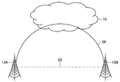
- ETWS In cellular systems (or mobile communication systems) represented by 3G, LTE, and LTE-A, ETWS is defined and implemented as a function mainly used for emergency message delivery such as disasters. First, an overview of ETWS will be described with reference to FIGS. 1 and 2.
- FIG. 1 is an explanatory diagram for explaining an outline of ETWS, and shows an example of a configuration of ETWS defined by 3GPP.
- ETWS is used mainly for emergency message delivery, but it can be used not only for delivery of emergency information such as disasters but also for delivery of information other than emergency information.
- a terminal device (UE) 300 As shown in FIG. 1, in the system configuration of ETWS, for example, in the case of 3G, CBE (Cell Broadcast Entity) 410, CBC (Cell Broadcast Center) 430, RNC (Radio Network Controller) 200 ′, And a terminal device (UE) 300.
- the terminal device 300 is also called a user.
- the user may also be referred to as user equipment (UE).
- the UE here may be a UE defined in LTE or LTE-A, and may more generally mean a communication device. In the following description, LTE and LTE-A may be simply referred to as “LTE”.
- CBE 410 corresponds to a message distribution source.
- the Japan Meteorological Agency corresponds to CBE410.
- the CBC 430 corresponding to the information delivery server in the cellular system receives a message delivery request from the CBE 410 and creates a corresponding delivery message.
- the CBC 430 transmits a message delivery request to the RNC 200 ′ corresponding to the radio network controller.
- the RNC 200 In response to the message distribution request transmitted from the CBC 430, the RNC 200 'distributes the message to the subordinate terminal apparatus 300 (for example, is broadcast).
- an MME (Mobility Management Entity) 450 and a base station (eNB: eNodeB) 200 are provided between the CBC 430 and the UE 300 instead of the RNC 200 ′. That is, the MME 450 is interposed between the CBC 430 and the base station 200.
- the base station 200 is a cellular system base station.
- the base station 200 performs wireless communication with the terminal device 300 located in the cell.
- the base station 200 transmits a downlink signal to the terminal device 300 and receives an uplink signal from the terminal device 300.
- the base station 200 may be a multi-cell system such as HetNet (Heterogeneous Network) or SCE (Small Cell Enhancement). That is, the base station 200 may be a macro cell base station that manages a so-called macro cell area, or may be a small cell base station that manages a so-called small cell area.
- HetNet Heterogeneous Network
- SCE Small Cell Enhancement
- the terminal device 300 performs wireless communication with the base station 200 in the cellular system. For example, the terminal device 300 receives a downlink signal from the base station 200 and transmits an uplink signal to the base station 200.
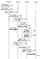
- FIG. 2 is a sequence diagram illustrating an example of an ETWS distribution flow in LTE.
- a request for message delivery (hereinafter also referred to as “information delivery request”) is transmitted from the CBE 410 to the CBC 430 (S103).
- the CBC 430 creates a message in accordance with the information delivery request from the CBE 410 (S105), and specifies an area for delivering the created message (S107). Then, the CBC 430 transmits a distribution request (for example, Write-Replace Warning Request) to the MME 450 that manages the identified area (S109).
- a distribution request for example, Write-Replace Warning Request
- the MME 450 Upon receiving the distribution request from the CBC 430, the MME 450 returns a response indicating that the message is distributed (for example, Write-Replace Warning Confirm) to the CBC 430 (S111).
- the CBC 430 receives a response to the distribution request from the MME 450, the CBC 430 responds to the information distribution request with respect to the CBE 410 that is the transmission source of the information distribution request (hereinafter referred to as “information distribution response”). (Also referred to as “)” (S113).
- the MME 450 confirms the base station 200 existing in the area to which the message is distributed from the base stations (eNBs) 200 under its control (S115), and sends a distribution request (for example, to the corresponding base station 200) , Write-Replace Warning Request is transmitted (S117).
- the base station 200 that has received the distribution request performs processing such as determination of a distribution area when there are a plurality of sectors or cells under control (S119), and distributes the message to the terminal device 300.
- the base station 200 first notifies the terminal device 300 that the message is distributed by transmitting a paging signal to the terminal device 300. (S121). Then, the base station 200 distributes the message as notification information to the terminal device 300 (S123). When the transmission of the message to the terminal device 300 is completed, the base station 200 returns a response (for example, Write-Replace Warning Confirm) to the MME 450 (S125).
- a response for example, Write-Replace Warning Confirm
- ETWS Primary Notification message and Secondary Notification message are defined as SystemInformationBlockType10 and 11 in the 3GPP standard.
- Table 1 below shows the format of the Primary Notification message of ETWS.
- Table 2 below shows the format of the ETWS Primary Notification message.
- the CMAS Notification message is specified as SystemInformationBlockType12 in the 3GPP standard.
- Table 3 shows the format of the CMAS Notification message.
- ETWS and CMAS messages shown above are distributed using a physical channel in LTE such as PBCH (Physical Broadcast Channel) or PDSCH (Physical Downlink Shared Channel).
- PBCH Physical Broadcast Channel
- PDSCH Physical Downlink Shared Channel
- emergency information notification based on a function such as ETWS is performed only for a terminal device existing in a communication area (or a cell provided by the base station) of a base station (or a so-called relay station). Is called.
- a terminal device existing outside the communication area of the base station is difficult to receive the emergency information even under a situation where the emergency information is notified from the base station.
- the content notified as emergency information is often the content that is desired to be notified to more users as quickly as possible, for example, information related to disasters such as earthquakes and tsunamis.
- the target for receiving emergency information is not necessarily limited to only terminal devices held by users.
- MTC Machine Type Communications
- V2X Vehicle-to-X (Something)
- the communication system is not limited to notifying emergency information only in a communication area such as a base station, but is a terminal device that exists in a wider range (in other words, We propose a mechanism capable of notifying emergency information to a larger number of terminal devices (in other words, a mechanism capable of further expanding the reach of emergency information).
- a communication area of a base station it can include a cell provided by the base station.
- FIG. 3 is a diagram for explaining an example of the configuration of the communication system according to the present embodiment.
- the communication system 1 includes an application server 10, a service platform 11, a network gateway 12, a device 13, an IP network 14, and a core network 15.
- the application server 10 is a server that provides a service.
- the service platform 11 is a server that provides an environment serving as a base for services provided by the application server 10.
- the network gateway 12 is a device having a function of mediating between different networks.
- the device 13 is a wireless communication device.
- the network gateway 12 is connected to the service platform 11 via the IP network 14.
- the device 13 is connected to the network gateway 12 via the core network 15.
- the device 13 may include a terminal device, a base station, a network manager, and the like.
- the terminal device is, for example, a user terminal.
- the base station is, for example, a NodeB, eNB, access point, or the like.
- the network manager has a function of managing the network.
- the terminal device, the base station, and the network manager are represented as the device 13 in the same layer, but may belong to different layers. When belonging to different layers, it is desirable that the layer to which the base station and the network manager belong is closer to the core network 15 than the layer to which the terminal device belongs.
- the terminal device belonging to the device 13 uses the service provided by the application server 10 via the network.
- a logical session related to the use of such a service can be understood as communication between the terminal device and the application server 10 indicated by reference numeral 21.
- a physical session related to the use of such a service can be understood as communication via various devices as indicated by reference numerals 22, 23 and 24.
- the terminal device is connected to the application server 10 via the base station, the core network 15, the network gateway 12, the IP network 14, and the service platform 11.
- the application server 10 may form the service platform 11 together with a plurality of other servers such as a cloud system. In that case, the service platform 11 may have a gateway function for connecting to the IP network 14.
- the service platform 11, the IP network 14, and the core network 15 include, as physical devices, a virtualization device that virtualizes a network such as a router, a switch, a router, or a switch, a virtualization control device that controls virtualization, Cables and the like can be included.
- FIG. 4 is a diagram for explaining a logical interface and a physical interface.
- the base stations 13 ⁇ / b> A and 13 ⁇ / b> B are connected by a logical interface 25. This interface is not necessarily physically connected.
- the base stations 13 ⁇ / b> A and 13 ⁇ / b> B can be physically connected by a physical interface 26 via a plurality of entities such as the core network 15.
- the interface between the base stations indicated by reference numerals 25 and 26 is also referred to as an X2 interface.
- the CBE 410, the CBC 430, and the MME 450 described with reference to FIGS. 1 and 2 correspond to examples of various entities (so-called logical entities).
- the communication system 1 includes a communication control device for cooperatively controlling communication in the communication system 1.
- the communication control device can be realized as, for example, the application server 10, the service platform 11, or the network manager 16.
- the communication control apparatus may be realized as a logical entity, and may be formed integrally with the base station, for example.
- the communication control apparatus may be realized as the CBE 410, CBC 430, and MME 450 described above with reference to FIGS.
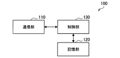
- FIG. 5 is a block diagram illustrating an example of a logical configuration of the communication control apparatus 100 according to the present embodiment.
- the communication control apparatus 100 includes a communication unit 110, a storage unit 120, and a control unit 130.
- the communication unit 110 is a communication interface that mediates communication with other devices by the communication control device 100.
- the communication unit 110 may be a wired communication interface or a wireless communication interface.
- the communication unit 110 can communicate using a plurality of connection methods including at least one of a multiple access method using orthogonal resources and a multiple access method using non-orthogonal resources. You may communicate with the radio
- FIG. Examples of the wireless communication device with which the communication unit 110 communicates include one or more terminal devices belonging to the device 13 and one or more base stations.
- orthogonal resources include time (subframe, slot, radio frame, etc.), frequency (component carrier, subcarrier, subchannel, resource block, etc.), code (spreading code, randomized code, etc.), and the like. It is done.
- Non-orthogonal resources include, for example, space (spatial stream, spatial layer, spatial codebook, antenna, antenna port, etc.), power (power, etc.), interleaver (bit interleaver, symbol interleaver, etc.), data rate, code ( Sparse code, spreading codebook, etc.). In the following description, these resources may be simply referred to as resources, but may be referred to variously.
- these resources include radio access resources (RAR: Radio Access Resources), radio resources (RR: Radio Resources), access resources (AR: Access Resources), radio access axes (RAA: Radio Access Axis), and radio access components.
- RAR Radio Access Resources
- RR Radio Resources
- AR Access Resources
- RAA Radio Access Axis
- RAU Radio Access Component
- RAB radio access block
- Storage unit 120 stores a program and data for the operation of the communication control apparatus 100 using a storage medium such as a hard disk or a semiconductor memory.
- Control unit 130 controls the overall operation of the communication control apparatus 100.
- the control unit 130 has a function of cooperatively controlling communication within the communication system 1.
- the control unit 130 may request the CBC 430 to distribute a message such as earthquake information or a tsunami warning (that is, an information distribution request). At this time, the control unit 130 may limit message distribution targets based on a predetermined condition.
- the control unit 130 may create a delivery message in response to a request from the CBE 410. Further, the control unit 130 may specify the distribution area according to the distribution target of the generated distribution message, and may control the communication unit 110 so that the distribution request is transmitted to the MME 450 that manages the specified distribution area. Good. Further, when a response to the distribution request is received from the MME 450, the control unit 130 responds to the CBE 410 that is the transmission source of the information distribution request by responding to the information distribution request (that is, the information distribution request). The communication unit 110 may be controlled so as to be returned as a response.
- the control unit 130 when the communication control apparatus 100 is realized as the MME 450, when the delivery request is received from the CBC 430, the control unit 130 returns a response indicating that the message is delivered to the CBC 430.
- the communication unit 110 may be controlled as described above. Further, the control unit 130 confirms the base station 200 existing in the area to which the message is to be distributed from the subordinate base stations 200 so that the distribution request is transmitted to the corresponding base station 200.
- the communication unit 110 may be controlled.
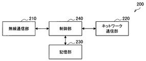
- FIG. 6 is a block diagram illustrating an example of a logical configuration of the base station 200 according to the present embodiment.
- the base station 200 includes a wireless communication unit 210, a network communication unit 220, a storage unit 230, and a control unit 240.
- the wireless communication unit 210 is a communication interface that mediates communication between the base station 200 and other devices.
- the wireless communication unit 210 performs wireless communication with one or more terminal devices 300 connected to the base station 200 using a connection method such as a multiple access method using orthogonal resources or a multiple access method using non-orthogonal resources. Do.
- the wireless communication unit 210 performs wireless communication with the terminal device 300 using the connection settings assigned by the communication control device 100.
- the network communication unit 220 is a communication interface for connecting the base station 200 to the core network 15.
- the network communication unit 220 may be a wired communication interface or a wireless communication interface.
- the network communication unit 220 transmits / receives data traffic and exchanges control messages with various control nodes in the core network 15.
- the network communication unit 220 can communicate with another base station 200 or the communication control apparatus 100 in the communication system 1.
- Storage unit 230 stores a program and data for the operation of the base station 200 using a storage medium such as a hard disk or a semiconductor memory.
- Control unit 240 controls the overall operation of the base station 200.
- the control unit 240 according to the present embodiment has a function of controlling the wireless communication unit 210 so as to perform wireless communication using resources allocated for the connection method used by the wireless communication unit 210.
- the control unit 240 sets the wireless communication unit 210 to use the connection method assigned by the communication control apparatus 100.
- the control unit 240 performs wireless communication using the spatial region, power region, interleaver region, data rate region, or sparse code region allocated by the communication control device 100 with respect to the connection method used by the wireless communication unit 210.
- the wireless communication unit 210 is set to perform.
- the control unit 240 may receive the message distribution request from the MME 450 and control the wireless communication unit 210 so that the message is distributed to the target terminal device 300. At this time, for example, the control unit 240 transmits a paging signal to the terminal device 300 to notify the terminal device 300 that the message is to be distributed based on the provisions such as ETWS. May be distributed to the terminal device 300. Further, the control unit 240 may limit a message distribution area (in other words, a sector or a cell). In addition, when a message is transmitted to the terminal device 300, the control unit 240 may control the wireless communication unit 210 so that a response is returned to the message distribution request from the MME 450.
- a message distribution area in other words, a sector or a cell
- control unit 240 controls the wireless communication unit 210 so that the terminal device 300 allocates resources for redistributing the message to the other terminal devices 300 and the terminal device 300 is notified of information regarding the allocated resources. May be.
- the control unit 240 may control the wireless communication unit 210 so that information about resources is broadcast to each terminal device 300 located in the distribution area (for example, cell). Good.
- the control unit 240 receives a request for resource allocation from the terminal device 300 and controls the wireless communication unit 210 so that the terminal device 300 is notified of information regarding the allocated resource. May be. Details will be described later.
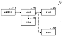
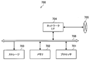
- FIG. 7 is a block diagram illustrating an example of a logical configuration of the terminal device 300 according to the present embodiment.
- the terminal device 300 includes a wireless communication unit 310, a storage unit 320, and a control unit 330.
- the terminal device 300 may include a notification unit 340.
- the terminal device 300 may include a vehicle unit 390.
- the wireless communication unit 310 is a wireless communication interface that mediates wireless communication with other devices by the terminal device 300.
- the wireless communication unit 310 according to the present embodiment performs wireless communication using at least one connection method of a multiple access method using orthogonal resources or a multiple access method using non-orthogonal resources.
- the wireless communication unit 310 performs wireless communication with the base station 200 using the connection setting assigned by the communication control apparatus 100.
- Storage unit 320 stores a program and data for the operation of the terminal device 300 using a storage medium such as a hard disk or a semiconductor memory.
- Notification unit 340 The alerting
- the notification unit 340 may notify the user of notification information corresponding to the content of a message distributed from the base station 200.
- Vehicle unit 390 schematically shows various configurations (for example, a drive system) and functions (for example, a security lock) of a vehicle device such as an automobile or a train.
- the operation of the vehicle unit 390 may be directly or indirectly controlled by the control unit 330 described later, for example.
- the vehicle unit 390 may control the configuration and functions related to the drive system (for example, an accelerator and a brake) based on an instruction from the control unit 330.
- the terminal device 300 including the vehicle unit 390 can correspond to a vehicle device such as a so-called automobile or train having a communication function with the base station 200. Further, the vehicle unit 390 may be provided outside the terminal device 300. In this case, the terminal device 300 may correspond to a so-called in-vehicle device installed in the vehicle device.
- Control unit 330 controls the overall operation of the terminal device 300.
- the control unit 330 according to the present embodiment has a function of controlling the wireless communication unit 310 so as to perform wireless communication using resources allocated for the connection method used by the wireless communication unit 310.
- the control unit 330 sets the wireless communication unit 310 to use the connection method assigned by the base station 200.
- the control unit 330 performs wireless communication using a spatial region, a power region, an interleaver region, a data rate region, or a sparse code region allocated by the base station 200 with respect to the connection method used by the wireless communication unit 310.
- the wireless communication unit 310 is set as follows.
- control unit 330 may cause the notification unit 340 to notify the notification information corresponding to the content of the message.
- control unit 330 may directly or indirectly control the operation of the vehicle unit 390 according to the content of the message distributed from the base station 200.
- the control unit 330 controls the operation of the wireless communication unit 310 so that the message is redistributed to other terminal devices 300 existing in the communication area. May be. At this time, the control unit 330 may control the operation of the wireless communication unit 310 so that the message is redistributed to other terminal devices 300 using the resources allocated by the base station 200. In this case, for example, the control unit 330 requests the base station 200 to allocate resources for redistributing the message to other terminal devices 300 by controlling the operation of the wireless communication unit 310. As a response, information regarding the allocated resource may be acquired.
- control unit 330 may acquire information about resources for redistributing a message to another terminal device 300 as information broadcast from the base station 200 (for example, system information). .
- control unit 330 may use a resource determined in advance according to a standard or the like for redelivery of a message to another terminal device 300. Details of the process will be described later.
- D2D Device-to-Device
- ProSe Proximity Service
- the terminal device 300 that has received a message such as emergency information from the base station 200 redistributes the received message to another terminal device 300 by using D2D.
- the communication system 1 according to the present embodiment not only the terminal device 300 located in the communication area of the base station 200 but also other terminal devices 300 located outside the communication area of the base station 200. Also, it is possible to distribute messages such as emergency information.
- the communication system 1 according to the present embodiment will be described in more detail.
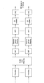
- FIG. 8 is a sequence diagram illustrating an example of a processing flow related to message redistribution. In this description, a description will be given focusing on a case where a message is distributed from the base station 200 to the terminal device 300a, and the terminal device 300a redistributes the message to another terminal device 300b. Further, in the example shown in FIG. 8, the communication processing flow between entities higher than the base station 200 is the same as the example described with reference to FIG. In FIG. 8, the processes indicated by reference numerals S201 to S215 are substantially the same as the processes indicated by reference numerals S109, S111, and S115 to S125 in the example shown in FIG. Is omitted.
- the terminal device 300a When the terminal device 300a receives a message from the base station 200 as broadcast information, the terminal device 300a confirms the content of the message (S217), and the message contains information of a predetermined type (for example, emergency information such as ETWS and CMAS). If included, it is determined to redistribute the message (S219).
- a predetermined type for example, emergency information such as ETWS and CMAS.
- the base station 200 sends a message from the terminal device 300a to another terminal device 300 (for example, the terminal device 300b) with respect to the terminal device 300a.
- Information indicating a radio resource for re-distributing is notified (S221).
- radio resources for redistribution for example, a physical channel for D2D, such as PSDCH (Physical Sidelink Discovery Channel), PSCCH (Physical Sidelink Control Channel), PSSCH (Physical Sidelink Shared Channel), or the like
- a resource pool for D2D such as a radio resource pool (Radio Resource Pool).
- the base station 200 indicates information indicating the radio resource to the terminal device 300a.
- the timing for notifying is not particularly limited.
- the terminal device 300a may notify the terminal device 300a of information indicating radio resources for redistribution as part of so-called system information.
- the terminal device 300a may notify information indicating a radio resource for redistribution together with the message.
- the base station 200 may notify the terminal device 300a of information indicating radio resources for redistribution using, for example, DCI (Downlink Control Information).
- the terminal device 300a confirms the radio
- the message is redistributed to the other terminal device 300b (S225).
- terminal device 300 redistributes a message distributed from base station 200 to another terminal device 300 using radio resources specified in advance by base station 200.
- An example has been described.
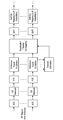
- FIG. 9 is a sequence diagram illustrating another example of a processing flow related to message redistribution.
- a message is distributed from the base station 200 to the terminal device 300a, and the terminal device 300a redistributes the message to another terminal device 300b.
- the communication processing flow between entities higher than the base station 200 is the same as the example described with reference to FIG. Omitted.
- the processes indicated by reference numerals S251 to S265 are substantially the same as the processes indicated by reference numerals S109, S111, and S115 to S125 in the example shown in FIG. Is omitted.
- the terminal device 300a When receiving the message from the base station 200 as the broadcast information, the terminal device 300a confirms the content of the message (S267), and the message is a predetermined type of information (for example, emergency information such as ETWS or CMAS). If so, it is determined to redistribute the message (S269).
- the processing so far is the same as the example described above with reference to FIG.
- the terminal device 300a requests the base station 200, which is the broadcast information distribution source, to allocate radio resources for redistributing the message distributed as the broadcast information to other terminal devices 300 (S271). ).
- the base station 200 Upon receiving a request from the terminal device 300a, the base station 200 allocates radio resources for the terminal device 300a to redistribute messages to other terminal devices 300 (S273). Further, the base station 200 notifies the terminal device 300a of information (that is, allocation information) indicating the radio resource allocated to the terminal device 300a (S277).
- the terminal device 300a confirms the radio
- the terminal device 300 requests the base station 200 to allocate radio resources to be used for redistributing the message distributed from the base station 200 to other terminal devices 300.
- An example of the case has been described.
- the communication system 1 for example, emergency information distributed from the base station 200 to the terminal device 300b located outside the communication area of the base station 200, etc. Message can be reached. Therefore, the communication system 1 according to the present embodiment has more terminal devices 300 located in a wider range than when the message is distributed only to the terminal devices 300 existing within the communication area of the base station 200. In contrast, it is possible to deliver a message.
- FIG. 10 is a flowchart illustrating an example of a flow of a series of processes related to message redistribution by the terminal device 300.
- the terminal device 300a receives message distribution from the base station 200 and the distributed message is emergency information (for example, CBE, ETWS, CMAS, etc.), the message is transferred to another terminal device.
- emergency information for example, CBE, ETWS, CMAS, etc.
- the terminal device 300a when receiving the broadcast information from the base station 200 (S301), the terminal device 300a confirms the message content distributed as the broadcast information (S303). When the message distributed as the notification information is not emergency information (S305, NO), the terminal device 300a determines not to redistribute the notification information (that is, the distributed message), and a series of The process ends (S307).
- the terminal device 300a determines to redistribute the notification information (S309).
- the terminal device 300a confirms radio resources to be used for redistribution of the broadcast information. For example, when radio resources for redistribution are designated in advance by system information or the like (S311: YES), the terminal device 300a uses the radio resources for redistribution of broadcast information (S313).
- the terminal device 300a can determine whether or not the base station 200 can request radio resource allocation (for example, the base station). The subsequent processing may be switched according to whether or not it is located within 200 cells (within the communication area).
- the terminal device 300a transmits a radio resource to be used for redistribution of broadcast information to the base station 200.
- An allocation is requested (S317).
- the base station 200 allocates radio resources for redistribution to the terminal device 300a, and notifies the terminal device 300a of information indicating the radio resources (that is, allocation information).
- the terminal device 300a confirms the information which shows the radio
- the terminal device 300a determines radio resources for redistribution by itself, and the radio resources Is used for redistribution of the notification information (S321). In this case, for example, the terminal device 300a may use a radio resource determined in advance based on a rule or the like for redistribution of broadcast information distributed from the base station 200.
- the terminal device 300a waits until the timing corresponding to the radio resource (S325). And when the timing corresponding to the radio
- FIG. 11 is a flowchart illustrating another example of a flow of a series of processes related to message redistribution by the terminal device 300, and when the radio resource for redistribution is not designated, the terminal device 300 shows an example of the operation when the broadcast information is not redistributed.
- the processes indicated by reference numerals S351 to S357 are substantially the same as the processes indicated by reference numerals S301 to S307 in FIG.
- the terminal device 300a checks whether or not a radio resource for redistributing the notification information is designated in advance. To do. When the radio resource for redistribution is not designated (S359, NO), the terminal device 300a determines not to redistribute the broadcast information (that is, the distributed message), and performs a series of processes. The process ends (S357).
- the terminal device 300a determines to redistribute the broadcast information (S361), and the specified radio resource is determined. It is used for redistribution of the notification information (S363).
- the terminal device 300a waits until the timing corresponding to the radio resource (S367).
- the terminal device 300a uses the radio resource used for redistribution to report information distributed from the base station 200. (S369).
- Table 4 shown below is used for transmission / reception of information between nodes when a terminal device 300 that has received a message from the base station 200 distributes the message to another terminal device 300.
- An example of a physical channel is shown.
- Table 4 shown below each of a case where radio resources are allocated in advance as in the example shown in FIG. 8 and a case where radio resources are allocated in response to a request from a terminal device as in the example shown in FIG. Shows about.
- the base station 200 delivers a message as broadcast information to the terminal device 300 (UE), for example, a physical broadcast channel (PBCH) or a downlink physical shared channel (PDSCH) is used.
- PBCH physical broadcast channel
- PDSCH downlink physical shared channel
- the base station 200 reserves D2D resources (that is, radio resources for redistribution) regularly or irregularly (that is, when a D2D resource pool is specified). obtain.
- the base station 200 may use, for example, PBCH or PDSCH for notification of information about the designation of the D2D resource.
- the terminal device 300 requests the base station 200 to allocate radio resources for redistributing the message distributed from the base station 200.
- the terminal apparatus 300 may use, for example, an uplink physical control channel (PUCCH: Physical Uplink Control Channel) or an uplink physical shared channel (PUSCH: Physical Uplink Shared Channel) for the request.
- the base station 200 in response to a radio resource allocation request from the terminal apparatus 300, notifies information indicating radio resources allocated to the terminal apparatus 300 (that is, allocation information). For this notification, for example, PBCH, PDSCH, or a downlink physical control channel (PDCCH: Physical Downlink Control Channel) may be used.
- the radio resource to be allocated in response to the request from the terminal device 300 is a D2D (Sidelink) radio resource
- the base station 200 uses the PBCH or PDSCH to indicate information indicating the radio resource. 300 may be notified.
- PSDCH Physical Sidelink Discovery Channel
- PSSCH Physical Sidelink Shared Channel
- radio resources for example, PSDCH, PSSCH, and PSCCH (Physical Sidelink Control Channel), etc.
- PSDCH has a high possibility of reaching more terminal apparatuses 300 among D2D resources. Therefore, it is more desirable to use PSDCH for redelivery of messages such as emergency information.
- the terminal device 300 uses another radio resource different from the radio resource used to receive the message.
- the terminal device 300 that has received the message distribution includes, as radio resources for redistributing the message, a frequency resource (subcarrier, resource block, component carrier, frequency channel, etc.) and a time resource ( At least one of a symbol, a slot, a subframe, a radio frame, a super frame, and the like) may use another radio resource different from the radio resource used for receiving the message.
- the method is not particularly limited as long as the terminal device 300 that has received the message can redistribute the message to another terminal device 300 located within its communication range.
- the terminal device 300 may redistribute the message with another terminal device 300 located within the communication range of the terminal device 300 as a destination (that is, the message may be unicast).
- the terminal device 300 redistributes the message by broadcasting (in other words, notifying) the message to the other terminal device 300 located within its communication range. Also good.
- a different method can be used for each target channel (wireless resource).
- the base station 200 and the terminal device 300 differ in signal processing capability, allowable power consumption, and the like. Therefore, by selecting the reception method and transmission method according to the performance and characteristics of each node, it becomes possible to optimize the frequency utilization efficiency and the power efficiency.
- Table 5 shown below shows an example of a combination of a transmission method and a reception method for a downlink channel, an uplink channel, and a side link (D2D) channel.
- an OFDMA Orthogonal frequency-division
- SC-FDMA Single Carrier-Frequency Division Multiple Access
- PAPR Peak-to-Average Power Ratio
- FIG. 12 is a flowchart illustrating an example of a process flow related to message reception by the terminal device 300.
- the terminal device 300 when the terminal device 300 is to receive broadcast information (that is, a message) (S401, YES), whether or not the information transmission method is different between the uplink and the downlink. Accordingly, the broadcast information reception method is switched.
- broadcast information that is, a message
- the terminal apparatus 300 determines whether the broadcast information is in accordance with whether or not the broadcast information is received on the downlink channel. Switch the reception method. That is, when broadcast information is about to be received on the downlink channel (S407, YES), the terminal device 300 uses a reception method for downlink signals such as OFDMA, for example (S409). If broadcast information is to be received on a channel other than the downlink (S407, NO), the terminal device 300 uses a reception method for uplink signals such as SC-FDMA, for example ( S411).
- the terminal device 300 may use a reception method for a predetermined signal (S405).
- the terminal device 300 receives the broadcast information based on the determined reception method (S413). Needless to say, as long as the terminal device 300 does not receive the notification information (S401, NO), the terminal device 300 does not execute the series of processes related to the reception of the notification information described above.
- FIG. 13 is a flowchart illustrating an example of a process flow related to message transmission by the terminal device 300.
- the terminal device 300 intends to transmit broadcast information (that is, a message) (S451, YES), whether or not the information transmission method is different between the uplink and the downlink. Accordingly, the broadcast information transmission method is switched.
- broadcast information that is, a message
- the terminal device 300 determines whether the broadcast information is transmitted according to whether the broadcast information is transmitted on the downlink channel. Switch the transmission method. That is, when broadcast information is to be transmitted on the downlink channel (S457, YES), the terminal device 300 uses a transmission method for downlink signals such as OFDMA, for example (S459). If broadcast information is to be transmitted on a channel other than the downlink (S457, NO), the terminal device 300 uses a transmission method for uplink signals such as SC-FDMA, for example ( S461).
- the terminal device 300 may use a predetermined signal transmission method (S405).
- the terminal device 300 transmits the notification information to the other terminal devices 300 based on the determined transmission method (S463). Needless to say, as long as the terminal device 300 does not transmit the notification information (S451, NO), the terminal device 300 does not execute the series of processes related to the transmission of the notification information described above.
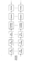
- an analog RF (Radio Frequency) signal received by each antenna element is subjected to frequency conversion and analog-to-digital conversion, and a CP ( Cyclic Prefix) is removed. Then, the received signal after CP removal (that is, the symbol series for each antenna element) is subjected to FFT (Fast Fourier Transform), thereby being subjected to OFDM (Orthogonal frequency-division multiple) demodulation (that is, multi-frequency).
- FFT Fast Fourier Transform
- OFDM Orthogonal frequency-division multiple
- equalization processing / spatial layer demapping is performed on the received signal subjected to OFMD demodulation.
- a reference signal added to a received signal is extracted, and equalization processing is performed on the received signal according to a channel characteristic estimated based on the reference signal. Thereby, a bit sequence for each layer is output. Then, the demapping process is performed on the bit sequence for each layer.
- deinterleaving, descrambling, rate matching, FEC (Forward Error Correction) decoding, and CRC (Cyclic Redundancy Check) decoding are performed on the bit sequence after the demapping process. Each process is performed. Thereby, the bit sequence for each layer is demodulated.
- FIG. 16 and FIG. 17 are block diagrams illustrating an example of a functional configuration related to information transmission by the terminal device 300, and illustrates an example when attention is paid to information transmission based on SC-FDMA.
- CRC coding for example, CRC coding, FEC coding, rate matching and scrambling / interleaving are performed on each bit sequence for each layer, and then modulation is performed. Precoding is applied.
- bit sequence for each antenna element is output by performing spatial layer mapping on the pre-coded bit sequence. Then, DFT (Discrete Fourier Transform), resource element mapping, IFFT (Inverse Fast Fourier Transform), CP insertion, and the like are performed on the bit sequence for each antenna element.
- DFT Discrete Fourier Transform
- resource element mapping resource element mapping
- IFFT Inverse Fast Fourier Transform
- CP insertion and the like are performed on the bit sequence for each antenna element.
- the symbol sequence with the CP inserted is subjected to digital to analog conversion and frequency conversion, and is output to each antenna element.
- the functional configuration of the terminal device 300 focusing on the transmission of information based on SC-FMDA, such as when the terminal device 300 transmits information to another terminal device 300.
- SC-FMDA the functional configuration of the terminal device 300 focusing on the transmission of information based on SC-FMDA, such as when the terminal device 300 transmits information to another terminal device 300.
- FIGS. 18 and 19 are block diagrams illustrating an example of a functional configuration related to information reception by the terminal device 300, and illustrates an example when attention is focused on reception of information based on SC-FDMA.
- the analog RF signal received by each antenna element is subjected to frequency conversion and analog-to-digital conversion, and a CP (Cyclic Prefix) added to the converted received signal is obtained.
- CP Cyclic Prefix
- Removed The received signal after CP removal (that is, the symbol sequence for each antenna element) is subjected to FFT (Fast Fourier Transform), and a reference signal is extracted. Mapping is applied. Thereby, a bit sequence for each layer is output. Then, IDFT and demapping processing are performed on the bit sequence for each layer.
- the de-interleaving, descrambling, rate matching, FEC decoding, and CRC decoding are performed on the bit sequence after the demapping process. Each bit sequence is demodulated.
- the functional configuration of the terminal device 300 focusing on reception of information based on SC-FMDA, such as when the terminal device 300 receives information from another terminal device 300.
- SC-FMDA reception of information based on SC-FMDA
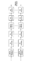
- FIG. 20 is a sequence diagram illustrating an example of a processing flow when the broadcast information distributed from the base station 200 is multi-hopped between the terminal devices 300.
- the communication processing flow between entities higher than the base station 200 is the same as the example described with reference to FIG.
- the processes indicated by reference numerals S501 to S515 are substantially the same as the processes indicated by reference numerals S207 to S215 and S225 in the example shown in FIG. The operation will be described focusing on the operation of the terminal device 300b.
- the terminal device 300b When receiving the message redistributed as the notification information from the terminal device 300a, the terminal device 300b confirms the content of the message (S517). When the received message is information of a predetermined type (for example, emergency information such as ETWS or CMAS), the terminal device 300b determines to redistribute the message (S519).
- a predetermined type for example, emergency information such as ETWS or CMAS
- the terminal device 300b redistributes the message redistributed as the notification information from the terminal device 300a to the other terminal device 300c using a predetermined radio resource (S521).
- the broadcast information can be distributed over a wider range.
- the multi-hop is performed excessively, radio resources are excessively consumed. It can be assumed that Therefore, a mechanism for limiting the number of times that broadcast information is multi-hopped between the terminal devices 300 may be provided.
- Table 6 below shows an example of IE (Information Elements) of broadcast information including information for limiting the number of hops.
- the IE of broadcast information shown in Table 6 is obtained by adding information (DistributionHopCount) indicating the number of hops to the format of the Primary Notification message of ETWS shown in Table 1, for example. DistributionHopCount is incremented every time broadcast information is distributed.
- DistributionHopCount is set to “1” in the broadcast information distributed from the base station 200 to the terminal device 300a.
- the DistributionHopCount of the broadcast information to be redistributed is incremented. That is, in the broadcast information redistributed from the terminal device 300a to the terminal device 300b, DistributionHopCount is set to “2”. Similarly, in the broadcast information redistributed from the terminal device 300b to the terminal device 300c, DistributionHopCount is set to “3”.
- the terminal device 300 that has received the broadcast information can recognize the number of hops related to the distribution of the broadcast information by referring to the DistributionHopCount of the broadcast information. Thereby, for example, when the number of hops of the broadcast information is equal to or greater than the threshold, the terminal device 300 that has received the broadcast information determines not to redistribute the broadcast information in order to avoid excessive multihop. May be.
- FIG. 21 is a flowchart illustrating an example of a flow of a series of processes of the terminal device 300 when the broadcast information is multi-hopped between the terminal devices 300.
- the multi-hop is different from the example illustrated in FIG. It is an example which added the control regarding. Therefore, in the present description, the example shown in FIG. 21 will be described by focusing on the parts different from the example shown in FIG. 10, and detailed description of the parts substantially the same as the example shown in FIG. 10 will be omitted.
- the terminal device 300b when receiving the notification information from the terminal device 300a (S601), the terminal device 300b confirms the message content distributed as the notification information (S603). If the message distributed as the notification information is not emergency information (S605, NO), the terminal device 300b determines not to redistribute the notification information (that is, the distributed message), and a series of The process ends (S611). This process is the same as the example described with reference to FIG.
- the terminal device 300b performs the subsequent processing depending on whether or not the content of the message has been received in the past. You may switch. Specifically, when the content of the message distributed as the notification information is the content that has been received in the past (NO in S607), the terminal device 300b relates to the notification information (that is, the distributed message). May not be redistributed, and the series of processing may be terminated (S611). This is because, if the content of the message distributed as the notification information is the content that the terminal device 300b has received in the past, the other terminal devices 300 to which the terminal device 300b redistributes the notification information are also similar.
- the terminal device 300b may determine whether the content of the message has been received in the past by going back a predetermined period from the present.
- the terminal device 300b determines whether the number of hops related to the distribution of the notification information is less than a threshold value. The subsequent processing may be switched depending on the situation. Specifically, when the number of hops is equal to or greater than the threshold (S609, NO), the terminal device 300b determines not to redistribute the notification information (that is, the distributed message), and ends the series of processes. It may be done (S611). Such control makes it possible to prevent the occurrence of a situation in which broadcast information is excessively multi-hopped. The number of hops can be recognized based on the value set in DistributionHopCount in the broadcast information as described with reference to Table 6, for example.
- the terminal device 300b determines to redistribute the notification information (S613). In this case, the terminal device 300b adds the number of hops of the broadcast information (for example, a value set in DistributionHopCount) (S615).
- the terminal device 300b may be redistributed to another terminal device 300 (for example, the terminal device 300c) using radio resources for redistribution.
- the terminal device 300b may operate so as not to redistribute broadcast information when radio resources for redistribution are not designated in advance.
- FIG. 22 is a flowchart illustrating another example of a flow of a series of processes of the terminal device 300 when the notification information is multi-hopped between the terminal devices 300. In contrast to the example illustrated in FIG. It is an example which added the control regarding multihop.
- the processes indicated by reference numerals S651 to S665 are substantially the same as the processes indicated by reference numerals S601 to 615 in the example shown in FIG. Further, the processes indicated by reference numerals S667 to S673 are substantially the same as the processes indicated by reference numerals S363 to S369 in the example shown in FIG. Therefore, detailed description of the example shown in FIG. 22 is omitted.
- the terminal device 300 transmits the message to another terminal device 300 by using another communication system different from the system (for example, the system under the base station 200 (cellular system)) that received the broadcast information.
- another communication system different from the system for example, the system under the base station 200 (cellular system)
- redistribution will be described.
- a message is distributed from the base station 200 to the terminal device 300a, and the terminal device 300a passes through another communication system different from the cellular system.
- An explanation will be given focusing on an example in which the message is redistributed to another terminal device 300b.
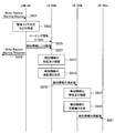
- FIG. 23 is a sequence diagram illustrating an example of a processing flow in a case where the terminal device 300 redistributes to another terminal device 300 using a communication system different from the system that has received the notification information.
- the terminal device 300a receives a message received from the base station 200, such as WLAN (Local Area Network), Wi-Fi (registered trademark), Bluetooth (registered trademark), or the like.
- the message is redistributed to the terminal device 300b connected via a communication system different from the cellular system.
- WLAN Local Area Network
- Wi-Fi registered trademark
- Bluetooth registered trademark
- the communication processing flow between entities higher than the base station 200 is the same as the example described with reference to FIG.
- the processes indicated by reference numerals S701 to S715 are substantially the same as the processes indicated by reference numerals S207 to S215 in the example shown in FIG. Description will be made by paying attention to the operation of the apparatus 300a.
- the terminal device 300a When the terminal device 300a receives the message distributed as the broadcast information from the base station 200, the terminal device 300a confirms the content of the message (S717). Then, when the received message includes information of a predetermined type (for example, emergency information such as ETWS or CMAS), the terminal device 300a determines to redistribute the message (S719).
- a predetermined type for example, emergency information such as ETWS or CMAS
- the terminal device 300a converts the protocol format (for example, IE) of the broadcast information distributed from the base station 200 according to the communication system to be redistributed (S721).
- the protocol format for example, IE
- S721 redistributed
- the terminal device 300a receives a message distributed as broadcast information from the base station 200 via communication established with the terminal device 300b (in other words, communication based on another communication system different from the cellular system). Is redistributed (S723).
- FIG. 24 shows an example of a flow of a series of processing of the terminal device 300 when the terminal device 300 redistributes to another terminal device 300 using a communication system different from the system that received the notification information. It is the shown flowchart.
- the terminal device 300a when receiving the notification information from the base station 200 (S751), the terminal device 300a confirms the message contents distributed as the notification information (S753).
- the message distributed as the notification information is not emergency information (S755, NO)
- the terminal device 300a determines not to redistribute the notification information (that is, the distributed message), and a series of The process ends (S757).
- the terminal device 300a determines to redistribute the notification information (S759). Then, the terminal device 300a retransmits the notification information distributed from the base station 200 to another terminal device 300 using the system that has received the notification information (that is, the system under the base station 200 (cellular system)). Distribute (S761).
- the terminal device 300a confirms whether another system different from the system that received the notification information can be used for redistribution of the notification information (that is, the message). When there is no other system that can be used for redistribution of broadcast information (S763, NO), the terminal device 300a performs a series of processes without performing redistribution of broadcast information via the other system. Exit.
- the terminal device 300a Redistribution of the notification information using is determined (S765).
- the terminal device 300a converts the protocol format (for example, IE) of the broadcast information in accordance with the other system that redistributes the broadcast information (S767).
- the terminal device 300a redistributes the broadcast information whose protocol format has been converted to another terminal device 300 (for example, the terminal device 300b shown in FIG. 23) using the other system (S769).
- the processes indicated by reference numerals S751 to S761 are executed, for example, as processes in a system (ie, a cellular system) under the base station 200. Further, the processes indicated by reference numerals S765 to S769 are executed as processes in a communication system different from the cellular system, such as WLAN, Wi-Fi (registered trademark), Bluetooth (registered trademark), and the like. .
- Table 7 shown below shows a conversion example of the protocol format of the broadcast information when the ETWS Primary Notification message described above as Table 1 is received as broadcast information.
- the terminal device 300a extracts the information of “warningType” as the redistribution target from the IEs of the Primary Notification message of ETWS received as the broadcast information, and other IEs ( That is, “messageIdentifie”, “serialNumber”, and “dummy”) are deleted. Then, based on the extracted “warningType” information, the terminal device 300a creates new notification information in accordance with the communication system used for redistribution of the notification information to the other terminal device 300b. Thereby, the protocol format of the broadcast information distributed from the base station 200 to the terminal device 300a is converted in accordance with another communication system in which the terminal device 300a redistributes the broadcast information to the terminal device 300b.
- Table 8 shown below shows a conversion example of the protocol format of the broadcast information when the ETWS Primary Notification message described above as Table 2 is received as broadcast information.
- the terminal device 300a extracts the information of “warningMessageSegment” from the IEs of the Primary Notification message of ETWS received as the broadcast information as a redistribution target, and other IEs ( That is, “dataCodingScheme”, “messageIdentifier”, “serialNumber”, “warningMessageSegmentNumber”, and “warningMessageSegmentType”) are deleted. And the terminal device 300a should just produce new alerting
- Table 9 shown below shows a conversion example of the protocol format of the broadcast information when the CMAS Notification message described above as Table 3 is received as broadcast information.
- the terminal device 300a extracts the information of “warningMessageSegment” from the IEs of the Primary Notification message of ETWS received as the broadcast information as a redistribution target, and other IEs ( That is, “dataCodingScheme”, “messageIdentifier”, “serialNumber”, “warningMessageSegmentNumber”, and “warningMessageSegmentType”) are deleted. And the terminal device 300a should just produce new alerting
- the terminal device 300 that has received (or redistributed) a predetermined type of message such as emergency information from the base station 200 or another terminal device 300 performs a predetermined operation according to the content of the message.
- a predetermined type of message such as emergency information from the base station 200 or another terminal device 300 performs a predetermined operation according to the content of the message. An example in the case of performing control will be described.
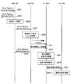
- FIG. 25 is a sequence showing an example of a processing flow when the terminal device 300 receives a predetermined type of message such as emergency information and executes predetermined operation control according to the content of the message.
- FIG. 25 the communication processing flow between entities higher than the base station 200 is the same as the example described with reference to FIG.
- the processes indicated by reference numerals S801 to S815 are substantially the same as the processes indicated by reference numerals S207 to S215 in the example shown in FIG. Description will be made by paying attention to the operations of the devices 300a and 300b.
- the terminal device 300a When the terminal device 300a receives a message distributed as broadcast information from the base station 200, the terminal device 300a confirms the content of the message (S817). If the received message is information of a predetermined type (for example, emergency information such as ETWS or CMAS), the terminal device 300a performs predetermined operation control according to the content of the message (S819). . As a specific example, when the terminal device 300a receives emergency information about a predetermined event such as a disaster or an accident, the terminal device 300a presents information about the event on the map information presented by the navigation device or the like. Also good. As another example, the terminal device 300a may control the operation of a vehicle with which the terminal device 300a is associated (for example, the vehicle unit 390 described above). Details of the predetermined operation control according to the content of the message by the terminal device 300 will be described later separately.
- a predetermined type for example, emergency information such as ETWS or CMAS
- the terminal device 300a may redistribute the broadcast information distributed from the base station 200 to the other terminal device 300b (S821).
- the terminal device 300b that has received the redistribution of the notification information (that is, the message) from the terminal device 300a may perform predetermined operation control according to the content of the message, similarly to the terminal device 300a (S823). ).
- the terminal device 300 when the terminal device 300 receives a predetermined type of message such as emergency information, an example of a sequence for executing predetermined operation control according to the content of the message Explained.
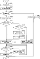
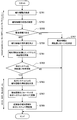
- FIG. 26 is a flowchart illustrating an example of a flow of a series of processing for operation control according to the content of emergency information by the terminal device 300.
- the terminal device 300 when receiving the notification information from the base station 200 (S841), the terminal device 300 confirms the message content distributed as the notification information (S843).
- the terminal device 300 executes various operation controls according to the contents of the emergency information.
- the terminal device 300 may switch the operation of the map display function to an operation for displaying emergency information (S849). Further, the terminal device 300 may perform a notice for alerting the user or the like depending on whether or not the terminal apparatus 300 is located in the attention area corresponding to the event notified as emergency information (S851). Further, the terminal device 300 may switch the operation related to the driving control of the vehicle with which the terminal device 300 is associated with, for example, an emergency operation (S853). A specific example of each operation control will be described later separately.
- the terminal device 300 may perform an operation according to the content of the notification information (S847).
- the terminal device 300 which has received the emergency information displays information related to the event indicated by the emergency information on the navigation device or the like. An example of the operation when presenting on the map information to be performed will be described.
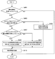
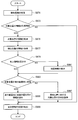
- FIG. 27 is a flowchart illustrating an example of a flow of a series of operations when the terminal device 300 that has received the emergency information presents information related to the event indicated by the emergency information on the map information. is there.
- the terminal device 300 when the terminal device 300 receives notification information about a predetermined event such as emergency information from the base station 200 (S871), the terminal device 300 also refers to a position related to the event (hereinafter, “target position”). It is confirmed whether or not it is possible to acquire information on And when the information regarding a target position is acquirable, the terminal device 300 will also show the information regarding a corresponding event on the map information which a navigation apparatus etc. show based on the information regarding the said target position, for example. Good.
- target position a position related to the event
- the terminal device 300 acquires the information on the target position (S875). At this time, the terminal device 300 may acquire information on the current position (S877).
- the terminal device 300 displays the map information on the display unit (S881). . Needless to say, if the map information is already displayed on the predetermined display unit (S879, YES), the map information need not be displayed again.
- the terminal device 300 executes various controls depending on whether or not the target position exists within the map information display range (for example, within a predetermined range based on the current position).
- the terminal device 300 displays information (for example, the target position) at a position corresponding to the target position on the map information (for example, Markers or the like) may be presented (S885).
- information for example, the target position
- map information for example, Markers or the like
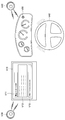
- FIG. 28 shows an example of a display when the content notified as emergency information is presented on map information.
- the terminal device 300 includes information V101 indicating the current position (that is, the position of the terminal device 300) and information V103 indicating the direction on the map information V100 displayed on the display unit or the like of the navigation device. May be presented. Further, the terminal device 300 may present the information V111 related to the event notified as emergency information and the information V113 (for example, the distance from the current position) about the position where the event has occurred on the map information V100. . As shown in FIG. 28, when the target position exists within the display range of the map information V100, the terminal device 300 moves the position of the target position to the position corresponding to the target position on the map information V100. May be presented in association with information V115 indicating.
- the terminal device 300 may present information indicating the direction of the target position with respect to the current position (S887).
- FIG. 29 shows another example of the display when the content notified as emergency information is presented on the map information.
- information indicated by reference numerals V100 to V113 respectively corresponds to information denoted by the same reference numerals in FIG.
- the terminal device 300 presents information V117 indicating the direction (direction) of the target position with respect to the current position on the map information V100. May be.
- the terminal device 300 when it is difficult to acquire the information of the target position (S873, NO), the terminal device 300 presents various information related to the event notified as emergency information on the map information described above. It is not necessary to perform the operation concerning.
- the terminal device 300 notifies the user that emergency information has been received, and presents information indicating the content notified as emergency information (S889). At this time, the terminal device 300 may present information indicating the content notified as emergency information in association with the position on the map information.
- the contents to be notified as emergency information include, for example, the occurrence time of emergency information, the specific contents of emergency information (for example, information on the event that has occurred), the current location of the terminal device 300, and a corresponding event. Information on the position (ie, the target position) and the like.
- the terminal device 300 visually presents, for example, the positional relationship between the position where the event occurred and the current position by presenting the content notified as emergency information on the map information.
- the content of the notification information can be notified to the user in a more preferable manner.
- FIG. 30 is a flowchart illustrating an example of a flow of a series of processes when the terminal device 300 executes notification to the user depending on whether or not the terminal device 300 is located in the attention area.
- the terminal device 300 that has received the emergency information distribution determines whether or not the terminal device 300 is within the caution area, depending on whether or not the target position and current position information can be acquired. The process according to the determination result is executed.
- the terminal device 300 compares the target position with the current position, thereby determining how much distance from the target position. It is estimated whether they are separated (S903). If the distance between the target position and the current position is within the threshold (S905, YES), the terminal device 300 notifies the user that it is located within the attention area (S907). A specific example of the information notification method will be described later.
- the terminal device 300 waits for a predetermined time (S913), and when the emergency information is not released (S915, NO), the series of processes indicated by reference numerals S903 to S913 are executed again.
- the emergency information is canceled (S915, YES)
- the terminal device 300 ends the series of processes.
- the terminal device 300 may not perform the series of processes described above.
- the terminal device 300 estimated the distance from the current position based on the target position (that is, the position where the event occurred) and the current position, but the event that was notified as emergency information. Accordingly, as the reference position for estimating the distance, another position may be used instead of the target position.
- Table 10 shown below is an example of setting a threshold of a distance between the current position determined to be in the attention area and a position serving as a reference for estimating a distance between the current position according to the event. Show.
- the terminal device 300 when the terminal device 300 receives emergency information notifying the occurrence of an event such as an incident, an accident, and a fire, the position where the event occurred is used as a reference. A 500 m range may be estimated as the attention area. Further, when the terminal device 300 receives emergency information for notifying the occurrence of an earthquake or tsunami, the terminal device 300 may estimate a 5 km range based on the position of the epicenter or the coastline near the epicenter as a caution area. Good. Further, when the terminal device 300 receives emergency information for notifying an eruption of a volcano, the terminal device 300 may estimate a 10 km range based on the position of the erupted volcano as a caution area.
- the example described above is merely an example, and is not necessarily limited to the example described above.
- terminal device 300 As described above, with reference to FIG. 30, as an example of operation control by terminal device 300, terminal device 300 that has received emergency information is determined whether or not itself is located in the attention area, and the determination result is determined. In the above, an example of processing in the case of notifying the user for alerting has been described.
- the terminal device 300 controls the operation of various control targets related to the operation of the vehicle, selects a route, and the like so as to be in a safer state according to an event notified as emergency information. May be executed.
- Table 11 shown below shows an example of settings of control items and control contents (control example) when the terminal device 300 controls the operation of the vehicle.
- the terminal device 300 may control operations related to vehicle operation such as the maximum speed of the vehicle and the rotational speed of the engine.
- the terminal device 300 estimates a caution area according to the content of the distributed emergency information, and controls the operation of the navigation device based on the estimation result, so that a route that avoids the caution area as much as possible is obtained.
- the calculated route may be presented to the user.
- the terminal device 300 may control the function related to the automatic driving according to the content of the distributed emergency information. Specifically, the terminal device 300 may control stop and start of automatic driving according to the content of emergency information. Further, the terminal device 300 may control the level of automatic driving, such as increasing or decreasing the number of items targeted for automatic driving according to the content of the emergency information.
- the terminal device 300 controls the operation of the vehicle and the operation of a device for assisting the operation of the vehicle, such as a navigation device, according to the event or content notified as emergency information. It also becomes possible to ensure the safety of the user.
- FIG. 31 is an explanatory diagram for describing an example of a notification mode of information from the terminal device 300 to the user.
- the terminal device 300 is, for example, the content of a message distributed via a display of an in-vehicle device such as a navigation device or a display unit such as a screen provided in the vehicle. Notification information corresponding to the user may be presented to the user. As a more specific example, the terminal device 300 may present information V11 indicating that the message has been received and text information V13 included in the message (that is, the body of the message) as display information via the display unit. Good.
- the terminal device 300 presents the URL via the display unit as indicated by reference numeral V15.
- the user may be prompted to refer to a link destination (for example, a response destination Web page) indicated by the URL.
- the display unit includes a touch panel
- the terminal device 300 has an interface (for example, a button) for starting a function (for example, a browser) for accessing the link destination indicated by the URL.
- You may show to a user via a display part. With such a configuration, the user can access the Web page to which the message is responded by operating the interface presented on the display unit, and can respond to the message.
- the terminal device 300 has received a message here, as shown by reference numeral V20, by presenting a predetermined icon on the dashboard or lighting an LED (Light Emitting Diode) or the like. This may be notified to the user. Further, as indicated by the reference sign V30, the terminal device 300 may notify the user that the message has been received by outputting voice or sound via an acoustic device such as a vehicle-mounted speaker. Further, as indicated by reference numeral V40, the terminal device 300 has received a message from the user by vibrating a device operated by the user (eg, a device to be gripped) such as a handle, for example. May be notified.
- a device operated by the user eg, a device to be gripped
- notification method described above is merely an example, and is not necessarily limited to the example described above. Moreover, it is not necessary to limit the method of alerting
- the terminal device 300 may notify the user of information according to the content of the message.
- the terminal device 300 when the terminal device 300 recognizes that the terminal device 300 is located within the caution area according to the content of the distributed emergency information, the terminal device 300 notifies the user of the information. Good.
- the terminal device 300 notifies the user of information according to the content of the distributed message has been described.
- the communication control apparatus 100 may be realized as any type of server such as a tower server, a rack server, or a blade server. Further, at least a part of the components of the communication control apparatus 100 is realized in a module (for example, an integrated circuit module configured by one die or a card or a blade inserted in a blade server slot) mounted on a server. May be.
- a module for example, an integrated circuit module configured by one die or a card or a blade inserted in a blade server slot mounted on a server. May be.
- the base station 200 may be realized as any type of eNB (evolved Node B) such as a macro eNB or a small eNB.
- the small eNB may be an eNB that covers a cell smaller than a macro cell, such as a pico eNB, a micro eNB, or a home (femto) eNB.
- the base station 200 may be realized as another type of base station such as a NodeB or a BTS (Base Transceiver Station).
- the base station 200 may include a main body (also referred to as a base station apparatus) that controls wireless communication, and one or more RRHs (Remote Radio Heads) that are arranged at locations different from the main body.
- RRHs Remote Radio Heads
- various types of terminals described later may operate as the base station 200 by temporarily or semipermanently executing the base station function.
- at least some components of the base station 200 may be realized in a base station device or a module for
- the terminal device 300 is a smartphone, a tablet PC (Personal Computer), a notebook PC, a portable game terminal, a mobile terminal such as a portable / dongle type mobile router or a digital camera, or an in-vehicle terminal such as a car navigation device. It may be realized as. Further, the terminal device 300 may be realized as a terminal (also referred to as an MTC (Machine Type Communication) terminal) that performs M2M (Machine To Machine) communication. Furthermore, at least a part of the components of the terminal device 300 may be realized in a module (for example, an integrated circuit module configured by one die) mounted on these terminals.
- MTC Machine Type Communication
- FIG. 32 is a block diagram illustrating an example of a schematic configuration of a server 700 to which the technology according to the present disclosure may be applied.
- the server 700 includes a processor 701, a memory 702, a storage 703, a network interface 704, and a bus 706.
- the processor 701 may be a CPU (Central Processing Unit) or a DSP (Digital Signal Processor), for example, and controls various functions of the server 700.
- the memory 702 includes a RAM (Random Access Memory) and a ROM (Read Only Memory), and stores programs and data executed by the processor 701.
- the storage 703 may include a storage medium such as a semiconductor memory or a hard disk.
- the network interface 704 is a wired communication interface for connecting the server 700 to the wired communication network 705.
- the wired communication network 705 may be a core network such as EPC (Evolved Packet Core) or a PDN (Packet Data Network) such as the Internet.
- EPC Evolved Packet Core
- PDN Packet Data Network
- the bus 706 connects the processor 701, the memory 702, the storage 703, and the network interface 704 to each other.
- the bus 706 may include two or more buses with different speeds (eg, a high speed bus and a low speed bus).
- a program for causing a processor to function as the communication unit 110, the storage unit 120, and the control unit 130 is a server.
- 700 may be installed and the processor 701 may execute the program.
- the server 700 may include a module including a processor 701 and a memory 702, and the communication unit 110, the storage unit 120, and the control unit 130 may be mounted in the module.
- the module may store a program for causing the processor to function as the communication unit 110, the storage unit 120, and the control unit 130 in the memory 702, and the processor 701 may execute the program.
- the server 700 or the module may be provided as a device including the communication unit 110, the storage unit 120, and the control unit 130.
- the processor 700 functions as the communication unit 110, the storage unit 120, and the control unit 130.
- the above program may be provided.
- a readable recording medium in which the program is recorded may be provided.
- FIG. 33 is a block diagram illustrating a first example of a schematic configuration of an eNB to which the technology according to the present disclosure may be applied.
- the eNB 800 includes one or more antennas 810 and a base station device 820. Each antenna 810 and the base station apparatus 820 can be connected to each other via an RF cable.
- Each of the antennas 810 has a single or a plurality of antenna elements (for example, a plurality of antenna elements constituting a MIMO antenna), and is used for transmission and reception of radio signals by the base station apparatus 820.
- the eNB 800 includes a plurality of antennas 810 as illustrated in FIG. 33, and the plurality of antennas 810 may respectively correspond to a plurality of frequency bands used by the eNB 800, for example. Note that although FIG. 33 illustrates an example in which the eNB 800 includes a plurality of antennas 810, the eNB 800 may include a single antenna 810.
- the base station apparatus 820 includes a controller 821, a memory 822, a network interface 823, and a wireless communication interface 825.
- the controller 821 may be a CPU or a DSP, for example, and operates various functions of the upper layer of the base station apparatus 820. For example, the controller 821 generates a data packet from the data in the signal processed by the wireless communication interface 825, and transfers the generated packet via the network interface 823. The controller 821 may generate a bundled packet by bundling data from a plurality of baseband processors, and may transfer the generated bundled packet. In addition, the controller 821 is a logic that executes control such as radio resource control, radio bearer control, mobility management, inflow control, or scheduling. May have a typical function. Moreover, the said control may be performed in cooperation with a surrounding eNB or a core network node.
- the memory 822 includes RAM and ROM, and stores programs executed by the controller 821 and various control data (for example, terminal list, transmission power data, scheduling data, and the like).
- the network interface 823 is a communication interface for connecting the base station device 820 to the core network 824.
- the controller 821 may communicate with the core network node or other eNB via the network interface 823.
- the eNB 800 and the core network node or another eNB may be connected to each other by a logical interface (for example, an S1 interface or an X2 interface).
- the network interface 823 may be a wired communication interface or a wireless communication interface for wireless backhaul.
- the network interface 823 may use a frequency band higher than the frequency band used by the wireless communication interface 825 for wireless communication.
- the wireless communication interface 825 supports any cellular communication scheme such as LTE (Long Term Evolution) or LTE-Advanced, and provides a wireless connection to terminals located in the cell of the eNB 800 via the antenna 810.
- the wireless communication interface 825 may typically include a baseband (BB) processor 826, an RF circuit 827, and the like.
- the BB processor 826 may perform, for example, encoding / decoding, modulation / demodulation, and multiplexing / demultiplexing, and each layer (for example, L1, MAC (Medium Access Control), RLC (Radio Link Control), and PDCP).
- Various signal processing of Packet Data Convergence Protocol
- Packet Data Convergence Protocol is executed.
- the BB processor 826 may have some or all of the logical functions described above instead of the controller 821.
- the BB processor 826 may be a module that includes a memory that stores a communication control program, a processor that executes the program, and related circuits. The function of the BB processor 826 may be changed by updating the program. Good.
- the module may be a card or a blade inserted into a slot of the base station apparatus 820, or a chip mounted on the card or the blade.
- the RF circuit 827 may include a mixer, a filter, an amplifier, and the like, and transmits and receives a radio signal via the antenna 810.
- the wireless communication interface 825 includes a plurality of BB processors 826 as illustrated in FIG. 33, and the plurality of BB processors 826 may respectively correspond to a plurality of frequency bands used by the eNB 800, for example. Further, the wireless communication interface 825 includes a plurality of RF circuits 827 as shown in FIG. 33, and the plurality of RF circuits 827 may respectively correspond to a plurality of antenna elements, for example.
- FIG. 33 shows an example in which the wireless communication interface 825 includes a plurality of BB processors 826 and a plurality of RF circuits 827. However, the wireless communication interface 825 includes a single BB processor 826 or a single RF circuit 827. But you can.
- the radio communication unit 210, the network communication unit 220, the storage unit 230, and the control unit 240 described with reference to FIG. 6 may be implemented in the radio communication interface 825.
- the eNB 800 illustrated in FIG. Alternatively, at least some of these components may be implemented in the controller 821.
- the eNB 800 includes a module including a part (for example, the BB processor 826) or the whole of the wireless communication interface 825 and / or the controller 821, and the wireless communication unit 210, the network communication unit 220, and the storage unit in the module. 230 and the controller 240 may be implemented.
- the module executes a program for causing the processor to function as the wireless communication unit 210, the network communication unit 220, the storage unit 230, and the control unit 240 (in other words, the processor executes the operation of the one or more components). May be stored and the program may be executed.
- a program for causing a processor to function as the radio communication unit 210, the network communication unit 220, the storage unit 230, and the control unit 240 is installed in the eNB 800, and the radio communication interface 825 (for example, the BB processor 826) and / or The controller 821 may execute the program.
- the eNB 800, the base station apparatus 820, or the module may be provided as an apparatus including the one or more components, and the processor is the wireless communication unit 210, the network communication unit 220, the storage unit 230, and the control unit.
- a program for functioning as 240 may be provided.
- a readable recording medium in which the program is recorded may be provided.
- the radio communication unit 210 described with reference to FIG. 6 may be implemented in the radio communication interface 825 (for example, the RF circuit 827).
- the network communication unit 220 may be implemented in the controller 821 and / or the network interface 823.
- the storage unit 230 may be mounted in the memory 822.
- FIG. 34 is a block diagram illustrating a second example of a schematic configuration of an eNB to which the technology according to the present disclosure may be applied.
- the eNB 830 includes one or more antennas 840, a base station apparatus 850, and an RRH 860. Each antenna 840 and RRH 860 may be connected to each other via an RF cable. Base station apparatus 850 and RRH 860 can be connected to each other via a high-speed line such as an optical fiber cable.
- Each of the antennas 840 has a single or a plurality of antenna elements (for example, a plurality of antenna elements constituting a MIMO antenna), and is used for transmission / reception of radio signals by the RRH 860.
- the eNB 830 includes a plurality of antennas 840 as illustrated in FIG. 34, and the plurality of antennas 840 may respectively correspond to a plurality of frequency bands used by the eNB 830, for example. 34 illustrates an example in which the eNB 830 includes a plurality of antennas 840, but the eNB 830 may include a single antenna 840.
- the base station device 850 includes a controller 851, a memory 852, a network interface 853, a wireless communication interface 855, and a connection interface 857.
- the controller 851, the memory 852, and the network interface 853 are the same as the controller 821, the memory 822, and the network interface 823 described with reference to FIG.
- the wireless communication interface 855 supports a cellular communication method such as LTE or LTE-Advanced, and provides a wireless connection to a terminal located in a sector corresponding to the RRH 860 via the RRH 860 and the antenna 840.
- the wireless communication interface 855 may typically include a BB processor 856 and the like.
- the BB processor 856 is the same as the BB processor 826 described with reference to FIG. 33 except that the BB processor 856 is connected to the RF circuit 864 of the RRH 860 via the connection interface 857.
- the wireless communication interface 855 includes a plurality of BB processors 856 as illustrated in FIG.
- the wireless communication interface 855 may include a single BB processor 856.
- connection interface 857 is an interface for connecting the base station device 850 (wireless communication interface 855) to the RRH 860.
- the connection interface 857 may be a communication module for communication on the high-speed line that connects the base station apparatus 850 (wireless communication interface 855) and the RRH 860.
- the RRH 860 includes a connection interface 861 and a wireless communication interface 863.
- connection interface 861 is an interface for connecting the RRH 860 (wireless communication interface 863) to the base station device 850.
- the connection interface 861 may be a communication module for communication on the high-speed line.
- the wireless communication interface 863 transmits and receives wireless signals via the antenna 840.
- the wireless communication interface 863 may typically include an RF circuit 864 and the like.
- the RF circuit 864 may include a mixer, a filter, an amplifier, and the like, and transmits and receives wireless signals via the antenna 840.
- the wireless communication interface 863 includes a plurality of RF circuits 864 as illustrated in FIG. 34, and the plurality of RF circuits 864 may correspond to, for example, a plurality of antenna elements, respectively. 34 shows an example in which the wireless communication interface 863 includes a plurality of RF circuits 864, the wireless communication interface 863 may include a single RF circuit 864.
- the wireless communication unit 210, the network communication unit 220, the storage unit 230, and the control unit 240 described with reference to FIG. 6 are implemented in the wireless communication interface 855 and / or the wireless communication interface 863. Also good. Alternatively, at least some of these components may be implemented in the controller 851. As an example, the eNB 830 includes a module including a part (for example, the BB processor 856) or the whole of the wireless communication interface 855 and / or the controller 851, and the wireless communication unit 210, the network communication unit 220, and the storage unit in the module. 230 and the controller 240 may be implemented.
- the module executes a program for causing the processor to function as the wireless communication unit 210, the network communication unit 220, the storage unit 230, and the control unit 240 (in other words, the processor executes the operation of the one or more components). May be stored and the program may be executed.
- a program for causing a processor to function as the wireless communication unit 210, the network communication unit 220, the storage unit 230, and the control unit 240 is installed in the eNB 830, and the wireless communication interface 855 (eg, the BB processor 856) and / or The controller 851 may execute the program.
- the eNB 830, the base station device 850, or the above module may be provided as a device including the wireless communication unit 210, the network communication unit 220, the storage unit 230, and the control unit 240.
- a program for causing the communication unit 220, the storage unit 230, and the control unit 240 to function may be provided.
- a readable recording medium in which the program is recorded may be provided.
- the wireless communication unit 210 described with reference to FIG. 4 may be implemented in the wireless communication interface 863 (for example, the RF circuit 864).
- the network communication unit 220 may be implemented in the controller 851 and / or the network interface 853.
- the storage unit 230 may be mounted in the memory 852.
- FIG. 35 is a block diagram illustrating an example of a schematic configuration of a smartphone 900 to which the technology according to the present disclosure may be applied.
- the smartphone 900 includes a processor 901, a memory 902, a storage 903, an external connection interface 904, a camera 906, a sensor 907, a microphone 908, an input device 909, a display device 910, a speaker 911, a wireless communication interface 912, one or more antenna switches 915.
- One or more antennas 916, a bus 917, a battery 918 and an auxiliary controller 919 are provided.
- the processor 901 may be, for example, a CPU or a SoC (System on Chip), and controls the functions of the application layer and other layers of the smartphone 900.
- the memory 902 includes a RAM and a ROM, and stores programs executed by the processor 901 and data.
- the storage 903 can include a storage medium such as a semiconductor memory or a hard disk.
- the external connection interface 904 is an interface for connecting an external device such as a memory card or a USB (Universal Serial Bus) device to the smartphone 900.
- the camera 906 includes, for example, an image sensor such as a CCD (Charge Coupled Device) or a CMOS (Complementary Metal Oxide Semiconductor), and generates a captured image.
- the sensor 907 may include a sensor group such as a positioning sensor, a gyro sensor, a geomagnetic sensor, and an acceleration sensor.
- the microphone 908 converts sound input to the smartphone 900 into an audio signal.
- the input device 909 includes, for example, a touch sensor that detects a touch on the screen of the display device 910, a keypad, a keyboard, a button, or a switch, and receives an operation or information input from a user.
- the display device 910 has a screen such as a liquid crystal display (LCD) or an organic light emitting diode (OLED) display, and displays an output image of the smartphone 900.
- the speaker 911 converts an audio signal output from the smartphone 900 into audio.
- the wireless communication interface 912 supports any cellular communication method such as LTE or LTE-Advanced, and performs wireless communication.
- the wireless communication interface 912 may typically include a BB processor 913, an RF circuit 914, and the like.
- the BB processor 913 may perform, for example, encoding / decoding, modulation / demodulation, and multiplexing / demultiplexing, and performs various signal processing for wireless communication.
- the RF circuit 914 may include a mixer, a filter, an amplifier, and the like, and transmits and receives radio signals via the antenna 916.
- the wireless communication interface 912 may be a one-chip module in which the BB processor 913 and the RF circuit 914 are integrated.
- the wireless communication interface 912 may include a plurality of BB processors 913 and a plurality of RF circuits 914 as illustrated in FIG. 35 illustrates an example in which the wireless communication interface 912 includes a plurality of BB processors 913 and a plurality of RF circuits 914, the wireless communication interface 912 includes a single BB processor 913 or a single RF circuit 914. It's okay.
- the wireless communication interface 912 may support other types of wireless communication methods such as a short-range wireless communication method, a proximity wireless communication method, or a wireless LAN (Local Area Network) method in addition to the cellular communication method.
- a BB processor 913 and an RF circuit 914 for each wireless communication method may be included.
- Each of the antenna switches 915 switches the connection destination of the antenna 916 among a plurality of circuits (for example, circuits for different wireless communication systems) included in the wireless communication interface 912.
- Each of the antennas 916 includes a single or a plurality of antenna elements (for example, a plurality of antenna elements constituting a MIMO antenna), and is used for transmission / reception of a radio signal by the radio communication interface 912.
- the smartphone 900 may include a plurality of antennas 916 as illustrated in FIG. Note that FIG. 35 illustrates an example in which the smartphone 900 includes a plurality of antennas 916, but the smartphone 900 may include a single antenna 916.
- the smartphone 900 may include an antenna 916 for each wireless communication method.
- the antenna switch 915 may be omitted from the configuration of the smartphone 900.
- the bus 917 connects the processor 901, the memory 902, the storage 903, the external connection interface 904, the camera 906, the sensor 907, the microphone 908, the input device 909, the display device 910, the speaker 911, the wireless communication interface 912, and the auxiliary controller 919 to each other.
- the battery 918 supplies electric power to each block of the smartphone 900 shown in FIG. 35 through a power supply line partially shown by a broken line in the drawing.
- the auxiliary controller 919 operates the minimum necessary functions of the smartphone 900 in the sleep mode.
- the wireless communication unit 310, the storage unit 320, the control unit 330, and the notification unit 340 described with reference to FIG. 7 may be implemented in the wireless communication interface 912.
- the smartphone 900 illustrated in FIG. Alternatively, at least some of these components may be implemented in the processor 901 or the auxiliary controller 919.
- the smartphone 900 includes a module including a part (for example, the BB processor 913) or the whole of the wireless communication interface 912, the processor 901, and / or the auxiliary controller 919.
- reporting part 340 may be mounted.
- the module is a program for causing the processor to function as the wireless communication unit 310, the storage unit 320, the control unit 330, and the notification unit 340 (in other words, the processor communicates with the wireless communication unit 310, the storage unit 320, and the control unit 330).
- a program for executing the operation of the notification unit 340 may be stored and the program may be executed.
- a program for causing the processor to function as the wireless communication unit 310, the storage unit 320, the control unit 330, and the notification unit 340 is installed in the smartphone 900, and the wireless communication interface 912 (for example, the BB processor 913) and the processor 901 are installed.
- the auxiliary controller 919 may execute the program.
- the smartphone 900 or the module may be provided as a device including the one or more components, and the processor functions as the wireless communication unit 310, the storage unit 320, the control unit 330, and the notification unit 340.
- a program may be provided.
- a readable recording medium in which the program is recorded may be provided.
- the wireless communication unit 310 described with reference to FIG. 7 may be implemented in the wireless communication interface 912 (for example, the RF circuit 914).
- the storage unit 320 may be mounted in the memory 902.
- FIG. 36 is a block diagram illustrating an example of a schematic configuration of a car navigation device 920 to which the technology according to the present disclosure can be applied.
- the car navigation device 920 includes a processor 921, a memory 922, a GPS (Global Positioning System) module 924, a sensor 925, a data interface 926, a content player 927, a storage medium interface 928, an input device 929, a display device 930, a speaker 931, and wireless communication.
- the interface 933 includes one or more antenna switches 936, one or more antennas 937, and a battery 938.
- the processor 921 may be a CPU or SoC, for example, and controls the navigation function and other functions of the car navigation device 920.
- the memory 922 includes RAM and ROM, and stores programs and data executed by the processor 921.
- the GPS module 924 measures the position (for example, latitude, longitude, and altitude) of the car navigation device 920 using GPS signals received from GPS satellites.
- the sensor 925 may include a sensor group such as a gyro sensor, a geomagnetic sensor, and an atmospheric pressure sensor.
- the data interface 926 is connected to the in-vehicle network 941 through a terminal (not shown), for example, and acquires data generated on the vehicle side such as vehicle speed data.
- the content player 927 reproduces content stored in a storage medium (for example, CD or DVD) inserted into the storage medium interface 928.
- the input device 929 includes, for example, a touch sensor, a button, or a switch that detects a touch on the screen of the display device 930, and receives an operation or information input from the user.
- the display device 930 has a screen such as an LCD or an OLED display, and displays a navigation function or an image of content to be reproduced.
- the speaker 931 outputs the navigation function or the audio of the content to be played back.
- the wireless communication interface 933 supports any cellular communication method such as LTE or LTE-Advanced, and performs wireless communication.
- the wireless communication interface 933 may typically include a BB processor 934, an RF circuit 935, and the like.
- the BB processor 934 may perform, for example, encoding / decoding, modulation / demodulation, and multiplexing / demultiplexing, and performs various signal processing for wireless communication.
- the RF circuit 935 may include a mixer, a filter, an amplifier, and the like, and transmits and receives a radio signal via the antenna 937.
- the wireless communication interface 933 may be a one-chip module in which the BB processor 934 and the RF circuit 935 are integrated.
- the wireless communication interface 933 may include a plurality of BB processors 934 and a plurality of RF circuits 935 as shown in FIG. 36 shows an example in which the wireless communication interface 933 includes a plurality of BB processors 934 and a plurality of RF circuits 935, the wireless communication interface 933 includes a single BB processor 934 or a single RF circuit 935. But you can.
- the wireless communication interface 933 may support other types of wireless communication methods such as a short-range wireless communication method, a proximity wireless communication method, or a wireless LAN method in addition to the cellular communication method.
- a BB processor 934 and an RF circuit 935 may be included for each communication method.
- Each of the antenna switches 936 switches the connection destination of the antenna 937 among a plurality of circuits included in the wireless communication interface 933 (for example, circuits for different wireless communication systems).
- Each of the antennas 937 has a single or a plurality of antenna elements (for example, a plurality of antenna elements constituting a MIMO antenna), and is used for transmission / reception of a radio signal by the radio communication interface 933.
- the car navigation device 920 may include a plurality of antennas 937 as shown in FIG. 36 illustrates an example in which the car navigation apparatus 920 includes a plurality of antennas 937, the car navigation apparatus 920 may include a single antenna 937.
- the car navigation device 920 may include an antenna 937 for each wireless communication method.
- the antenna switch 936 may be omitted from the configuration of the car navigation device 920.
- the battery 938 supplies power to each block of the car navigation device 920 shown in FIG. 36 via a power supply line partially shown by broken lines in the drawing. Further, the battery 938 stores electric power supplied from the vehicle side.
- the car navigation apparatus 920 includes a module including a part (for example, the BB processor 934) or the whole of the wireless communication interface 933 and / or the processor 921, and the one or more components are mounted in the module. May be.
- the module stores a program for causing the processor to function as the one or more components (in other words, a program for causing the processor to execute the operation of the one or more components). The program may be executed.
- a program for causing the processor to function as the wireless communication unit 310, the storage unit 320, the control unit 330, and the notification unit 340 is installed in the car navigation device 920, and the wireless communication interface 933 (for example, the BB processor 934) and The processor 921 may execute the program.
- the car navigation device 920 or the module may be provided as a device including the wireless communication unit 310, the storage unit 320, the control unit 330, and the notification unit 340, and the processor may be provided with the wireless communication unit 310, the storage unit 320,
- a program for functioning as the control unit 330 and the notification unit 340 may be provided.
- a readable recording medium in which the program is recorded may be provided.
- the wireless communication unit 310 described with reference to FIG. 7 may be implemented in the wireless communication interface 933 (for example, the RF circuit 935).
- the storage unit 320 may be mounted in the memory 922.
- an in-vehicle system (or vehicle) 940 including one or more blocks of the car navigation device 920 described above, an in-vehicle network 941, and a vehicle side module 942. That is, an in-vehicle system (or vehicle) 940 may be provided as a device including the wireless communication unit 310, the storage unit 320, the control unit 330, and the notification unit 340.
- the vehicle-side module 942 generates vehicle-side data such as vehicle speed, engine speed, or failure information, and outputs the generated data to the in-vehicle network 941.
- vehicle unit 390 described with reference to FIG. 7 corresponds to an example of the vehicle-side module 942.
- the terminal device 300 when the terminal device 300 receives broadcast information (that is, a message) from the base station 200, the broadcast information is converted into information of a predetermined type (for example, In the case where emergency information or the like is included, the notification information is redistributed to another terminal device 300. At this time, the terminal device 300 may redistribute the broadcast information to another terminal device 300 via another system different from the system under the base station 200. Further, the broadcast information to be redistributed may be multi-hopped between the terminal devices 300.
- broadcast information that is, a message
- the broadcast information is converted into information of a predetermined type (for example, In the case where emergency information or the like is included, the notification information is redistributed to another terminal device 300.
- the terminal device 300 may redistribute the broadcast information to another terminal device 300 via another system different from the system under the base station 200. Further, the broadcast information to be redistributed may be multi-hopped between the terminal devices 300.
- the communication system 1 according to the present embodiment for example, the emergency information distributed from the base station 200 to the terminal device 300 located outside the communication area of the base station 200, etc.
- the message can be reached. Therefore, the communication system 1 according to the present embodiment has more terminal devices 300 located in a wider range than when the message is distributed only to the terminal devices 300 existing within the communication area of the base station 200. In contrast, it is possible to deliver a message directly or indirectly.
- information that requires urgency such as emergency information, can be notified to more users in a more preferable manner. It becomes possible.
- a communication unit for performing wireless communication An acquisition unit for acquiring notification information from the first device via the wireless communication; A communication control unit configured to control so that the notification information is transmitted from the communication unit to a second device located within a predetermined communication range when the acquired notification information includes information of a predetermined type; , An apparatus comprising: (2) The first device is a base station; The acquisition unit acquires information indicating a radio resource from the base station, The communication control unit controls the broadcast information to be transmitted from the communication unit to the second device via the radio resource; The apparatus according to (1) above. (3) The apparatus according to (2), wherein the acquisition unit acquires information indicating the radio resource from the base station after the base station is requested to allocate the radio resource.
- the communication control unit controls the broadcast information to be transmitted to the second device based on another communication method different from the communication method used for communication with the first device.
- the apparatus according to any one of (1) to (3).
- the communication control unit controls the broadcast information to be transmitted to the second device via another radio resource different from a radio resource used for communication with the first device.
- the apparatus according to any one of (1) to (4).
- (6) The device according to (1), wherein the communication control unit controls the broadcast information to be transmitted to the second device via a predetermined radio resource.
- the communication control unit controls the broadcast information to be transmitted to the second device belonging to another communication system different from the communication system to which the first device belongs.
- the apparatus according to any one of (6).
- the first device is a terminal;
- the communication control unit controls transmission of the broadcast information to the second device according to the number of terminals relayed until the broadcast information transmitted from a base station is acquired by the acquisition unit.
- the apparatus according to (1) above.
- Information indicating radio resources for the first device to redistribute the notification information distributed to the first device to the second device is notified from the communication unit to the first device.
- a communication control unit for controlling An apparatus comprising: (10) The apparatus according to (9), wherein the communication control unit controls the first apparatus located within a predetermined communication range to be notified of information indicating the radio resource.
- the communication control unit Controlling the broadcast information to be transmitted to the first device; The apparatus according to (9), wherein control is performed so that information indicating the radio resource is notified to the first apparatus to which the broadcast information is transmitted. (12) The communication control unit is notified of information indicating the radio resource to the first device after receiving a request regarding the allocation of the radio resource from the first device to which the broadcast information is transmitted.
- a communication unit for performing wireless communication An acquisition unit for acquiring notification information from an external device via the wireless communication; A control unit that controls an operation related to at least one of a vehicle and a navigation device according to the content of the notification information when the acquired notification information includes a predetermined type of information;
- An apparatus comprising: (14)
- the notification information includes information on the event that has occurred,
- the said control part is an apparatus as described in said (13) which controls the operation
- the notification information includes information on a position where the event has occurred,
- the said control part is an apparatus as described in said (14) which controls the operation
- produced is shown on map information.
- the said control part is an apparatus as described in said (15) which shows the information which shows the direction of the position where the said event generate
- the notification information includes information on the event that has occurred, The apparatus according to any one of (13) to (17), wherein the control unit controls the operation of the vehicle according to information related to the event. (19) Doing wireless communication, Obtaining notification information from the first device via the wireless communication; The processor, when the acquired notification information includes a predetermined type of information, controlling the notification information to be transmitted to a second device located within a predetermined communication range; Including the method.
- Doing wireless communication Information indicating a radio resource for the processor to redistribute broadcast information distributed to the first device to the second device is notified to the first device.
- Doing wireless communication Obtaining notification information from an external device via the wireless communication; A processor controlling an operation related to at least one of a vehicle and a navigation device according to a content of the notification information when the acquired notification information includes information of a predetermined type; Including the method.
- On the computer Doing wireless communication, Obtaining notification information from an external device via the wireless communication; Controlling the operation of at least one of the vehicle and the navigation device according to the content of the notification information when the acquired notification information includes information of a predetermined type; A program that executes
- communication system 100 communication control device 110 communication unit 120 storage unit 130 control unit 200 base station 210 wireless communication unit 220 network communication unit 230 storage unit 240 control unit 300 terminal device 300 base station 310 wireless communication unit 320 storage unit 330 control unit 340 Notification unit 390 Vehicle unit
Landscapes
- Engineering & Computer Science (AREA)
- Signal Processing (AREA)
- Computer Networks & Wireless Communication (AREA)
- Emergency Management (AREA)
- Business, Economics & Management (AREA)
- Health & Medical Sciences (AREA)
- Environmental & Geological Engineering (AREA)
- Public Health (AREA)
- Quality & Reliability (AREA)
- Computer Security & Cryptography (AREA)
- Mobile Radio Communication Systems (AREA)
- Telephonic Communication Services (AREA)
- Alarm Systems (AREA)
Abstract
Description
1.緊急情報の報知機能
1.1.ETWS
1.2.メッセージフォーマットの一例
2.技術的課題
3.構成例
3.1.通信システム
3.2.通信制御装置
3.3.基地局
3.4.端末装置
4.技術的特徴
4.1.メッセージの再配信に係るシーケンスの一例
4.2.端末装置によるメッセージの再配信
4.3.ノード間における情報の送受信の制御例
4.4.端末装置間における報知情報のマルチホップ
4.5.異なる通信システムを利用した再配信
4.6.メッセージの配信を受けた端末装置の動作
5.応用例
5.1.通信制御装置に関する応用例
5.2.基地局に関する応用例
5.3.端末装置に関する応用例
6.むすび
3G、LTE(Long Term Evolution)及びLTE-A(LTE-Advanced)等の規格に基づくセルラーシステム等のような所謂通信システムでは、通信エリア内の端末装置(ユーザ)に対して緊急情報を報知するための機能が提供されている場合がある。このような緊急情報を報知するための機能は、例えば、CBE(Cell Broadcast Emergency)、CMAS(Commercial Mobile Alert Service)、ETWS(Earthquake and Tsunami Warning System)等のように呼ばれている場合がある。3GPPが規定する通信規約(特に、LTE)では、例えば、CMAS及びETWSがシステム情報(System Information)として規格化されている。
3G、LTE、及びLTE-Aに代表されるセルラーシステム(又は移動体通信システム)には、災害等の緊急メッセージ配信を主な用途とした機能として、ETWSが規定及び実装されている。そこで、まず、図1及び図2を参照して、ETWSの概要について説明する。
次いで、緊急情報を報知するためのメッセージのフォーマットの一例として、特に、LTEにおいて規定されたETWS及びCMASのメッセージフォーマットについて、参考として以下に提示する。


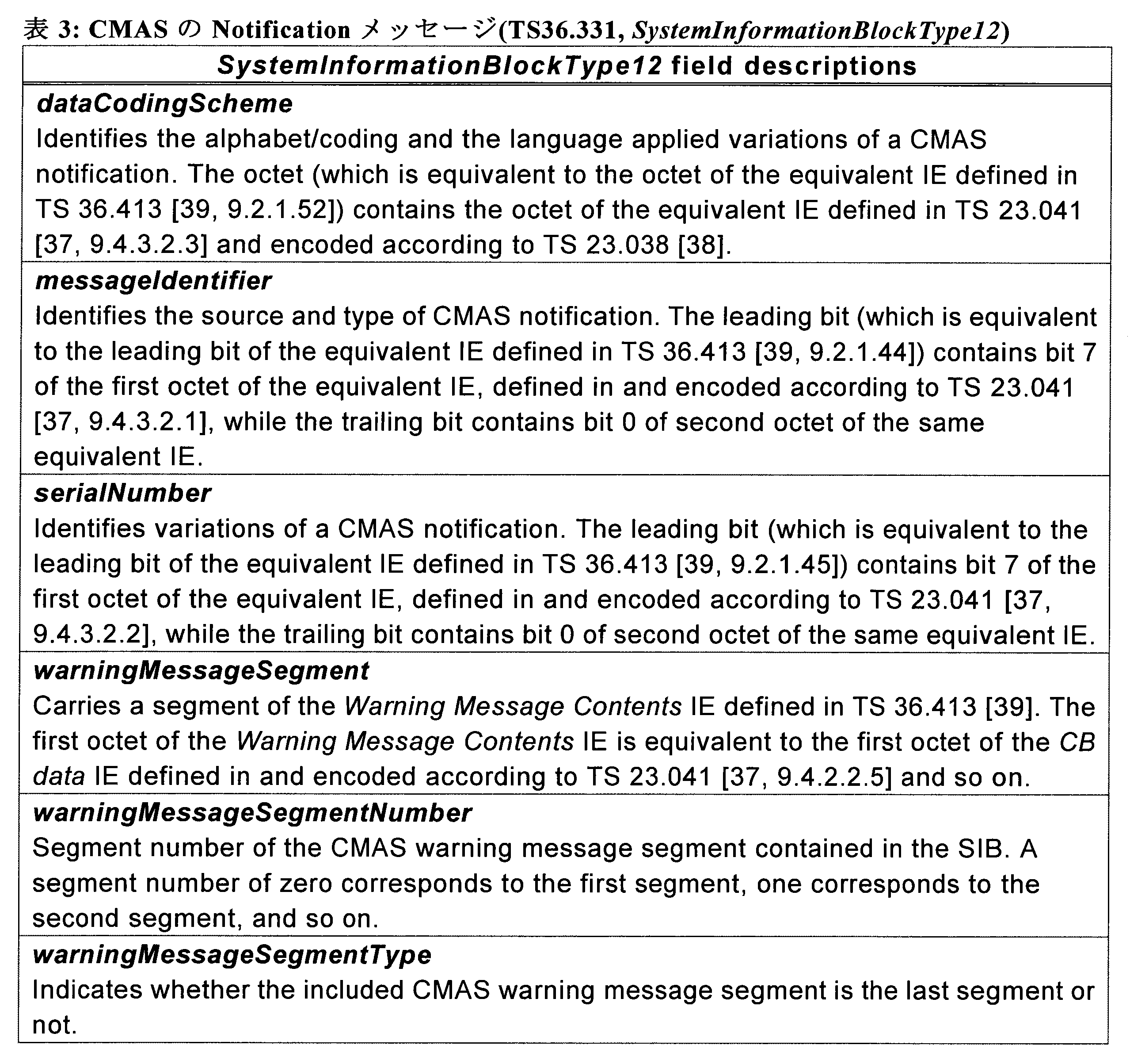
次に、本開示の実施形態に係る技術的課題について説明する。前述したように、ETWS等の機能に基づく緊急情報の報知は、基地局(または、所謂リレー局)の通信エリア(または、基地局が提供するセル)内に存在する端末装置に対してのみ行われる。このような場合には、例えば、基地局の通信エリア外に存在する端末装置は、基地局から緊急情報が報知されるような状況下においても、当該緊急情報を受信することが困難である。
<3.1.通信システム>
まず、図3~図4を参照して、本実施形態に係る通信システムの全体構成について説明する。
本実施形態に係る通信システム1は、通信システム1内の通信を協調的に制御するための通信制御装置を含む。通信制御装置は、例えば、アプリケーションサーバ10、サービスプラットフォーム11、又はネットワークマネージャ16として実現され得る。通信制御装置は、論理的エンティティとして実現されてもよく、例えば基地局と一体的に形成されてもよい。より具体的な一例として、通信制御装置は、図1及び図2を参照して前述したCBE410、CBC430、及びMME450として実現され得る。
通信部110は、通信制御装置100による他の装置との通信を仲介する通信インタフェースである。通信部110は、有線通信インタフェースであってもよく、又は無線通信インタフェースであってもよい。具体的な一例として、通信部110は、直交リソースを用いた多元接続方式又は非直交リソースを用いた多元接続方式の少なくともいずれかの接続方式を含む複数の接続方式を利用して通信可能な通信システム1の無線通信装置と通信を行ってもよい。通信部110が通信を行う無線通信装置としては、例えばデバイス13に属する一つ以上の端末装置及び一つ以上の基地局が挙げられる。
記憶部120は、ハードディスク又は半導体メモリなどの記憶媒体を用いて、通信制御装置100の動作のためのプログラム及びデータを記憶する。
制御部130は、通信制御装置100の動作全般を制御する。制御部130は、通信システム1内の通信を協調的に制御する機能を有する。
図6は、本実施形態に係る基地局200の論理的な構成の一例を示すブロック図である。図6に示すように、基地局200は、無線通信部210、ネットワーク通信部220、記憶部230及び制御部240を含む。
無線通信部210は、基地局200による他の装置との通信を仲介する通信インタフェースである。無線通信部210は、直交リソースを用いた多元接続方式又は非直交リソースを用いた多元接続方式等の接続方式を利用して、基地局200に接続する一つ以上の端末装置300と無線通信を行う。例えば、無線通信部210は、通信制御装置100により割り当てられた接続設定を用いて端末装置300との間で無線通信を行う。
ネットワーク通信部220は、基地局200をコアネットワーク15に接続するための通信インタフェースである。ネットワーク通信部220は、有線通信インタフェースであってもよく、又は無線通信インタフェースであってもよい。ネットワーク通信部220は、コアネットワーク15内の様々な制御ノードとの間で、データトラフィックを送受信し、及び制御メッセージを交換する。ネットワーク通信部220は、通信システム1内の他の基地局200又は通信制御装置100との間で通信を行い得る。
記憶部230は、ハードディスク又は半導体メモリなどの記憶媒体を用いて、基地局200の動作のためのプログラム及びデータを記憶する。
制御部240は、基地局200の動作全般を制御する。本実施形態に係る制御部240は、無線通信部210が利用する接続方式に関して割り当てられたリソースを用いた無線通信を行うよう無線通信部210を制御する機能を有する。例えば、制御部240は、通信制御装置100により割り当てられた接続方式を利用するよう無線通信部210を設定する。そして、制御部240は、無線通信部210が利用する接続方式に関して、通信制御装置100により割り当てられた空間領域、電力領域、インタリーバ領域、データレート領域、又はスパース符号領域を利用して無線通信を行うように無線通信部210を設定する。
図7は、本実施形態に係る端末装置300の論理的な構成の一例を示すブロック図である。図7に示すように、端末装置300は、無線通信部310、記憶部320及び制御部330を有する。また、端末装置300は、報知部340を含んでもよい。また、端末装置300は、車両部390を含んでもよい。
無線通信部310は、端末装置300による他の装置との無線通信を仲介する無線通信インタフェースである。本実施形態に係る無線通信部310は、直交リソースを用いた多元接続方式又は非直交リソースを用いた多元接続方式の少なくともいずれかの接続方式をひとつ以上用いて無線通信を行う。例えば、無線通信部310は、通信制御装置100により割り当てられた接続設定を用いて基地局200との間で無線通信を行う。
記憶部320は、ハードディスク又は半導体メモリなどの記憶媒体を用いて、端末装置300の動作のためのプログラム及びデータを記憶する。
報知部340は、ディスプレイ、スピーカ、振動デバイス等の出力デバイスを用いて、ユーザに情報を報知する。例えば、報知部340は、基地局200から配信されたメッセージの内容に応じた報知情報をユーザに報知してもよい。
車両部390は、自動車や電車等の車両装置の各種構成(例えば、駆動系等)や機能(例えば、セキュリティロック等)を模式的に示している。車両部390は、例えば、後述する制御部330により、その動作が直接的または間接的に制御されてもよい。より具体的な一例として、自動車の自動運転の例が挙げられる。この場合には、例えば、車両部390は、制御部330からの指示に基づき、駆動系に関する構成や機能(例えば、アクセルやブレーキ)が制御されてもよい。
制御部330は、端末装置300の動作全般を制御する。本実施形態に係る制御部330は、無線通信部310が利用する接続方式に関して割り当てられたリソースを用いた無線通信を行うよう無線通信部310を制御する機能を有する。例えば、制御部330は、基地局200により割り当てられた接続方式を利用するよう無線通信部310を設定する。そして、制御部330は、無線通信部310が利用する接続方式に関して、基地局200により割り当てられた空間領域、電力領域、インタリーバ領域、データレート領域、又はスパース符号領域を利用して無線通信を行うよう無線通信部310を設定する。
続いて、本開示の一実施形態に係る技術的特徴について説明する。
まず、本開示の一実施形態に係る通信システム1において、端末装置300が基地局200から配信されたメッセージを他の端末装置300に再配信する場合のシーケンスの一例について説明する。
まず、図8を参照して、端末装置300が、基地局200によりあらかじめ指定された無線リソースを利用して、当該基地局200から配信されたメッセージを他の端末装置300に再配信する場合の一例について説明する。図8は、メッセージの再配信に係る処理フローの一例を示したシーケンス図である。なお、本説明では、基地局200から端末装置300aに対してメッセージが配信され、当該端末装置300aが他の端末装置300bに対して当該メッセージを再配信する場合に着目して説明する。また、図8に示す例において、基地局200より上位のエンティティ間における通信の処理フローについては、図2を参照して説明した例と同様のため図示を省略している。また、図8において、参照符号S201~S215で示された処理は、図2に示す例において参照符号S109、S111、及びS115~S125で示された処理と実質的に同様のため、詳細な説明は省略する。
次いで、図9を参照して、端末装置300が、基地局200から配信されたメッセージを他の端末装置300に再配信するために利用する無線リソースの割り当てを、当該基地局200に対して依頼する場合の一例について説明する。図9は、メッセージの再配信に係る処理フローの他の一例を示したシーケンス図である。なお、本説明では、図8に示す例と同様に、基地局200から端末装置300aに対してメッセージが配信され、当該端末装置300aが他の端末装置300bに対して当該メッセージを再配信する場合に着目して説明する。また、図9に示す例においても、図8に示す例と同様に、基地局200より上位のエンティティ間における通信の処理フローについては、図2を参照して説明した例と同様のため図示を省略している。また、図9において、参照符号S251~S265で示された処理は、図2に示す例において参照符号S109、S111、及びS115~S125で示された処理と実質的に同様のため、詳細な説明は省略する。
次いで、端末装置300が基地局200から配信されたメッセージを他の端末装置300に配信する場合の一連の処理の流れの一例について説明する。例えば、図10は、端末装置300によるメッセージの再配信に係る一連の処理の流れの一例を示したフローチャートである。なお、本説明では、端末装置300aが、基地局200からメッセージの配信を受けて、配信されたメッセージが緊急情報(例えば、CBE、ETWS、CMAS等)の場合に、当該メッセージを他の端末装置300bに再配信するものとして説明する。
次に、基地局-端末装置間や、端末装置-端末装置間等のような各ノード間におけるメッセージ等の情報の送受信に係る制御の一例について説明する。
まず、ノード間における情報の送受信に係る設定の一例について説明する。例えば、以下に示す表4は、基地局200からのメッセージの配信を受けた端末装置300が、当該メッセージを他の端末装置300に配信する場合における、各ノード間における情報の送受信に利用される物理チャネルの一例を示している。以下に示す表4では、図8に示す例のように、無線リソースを事前に割り当てる場合と、図9に示す例のように、端末装置からのリクエストに応じて無線リソースを割り当てる場合とのそれぞれについて示している。

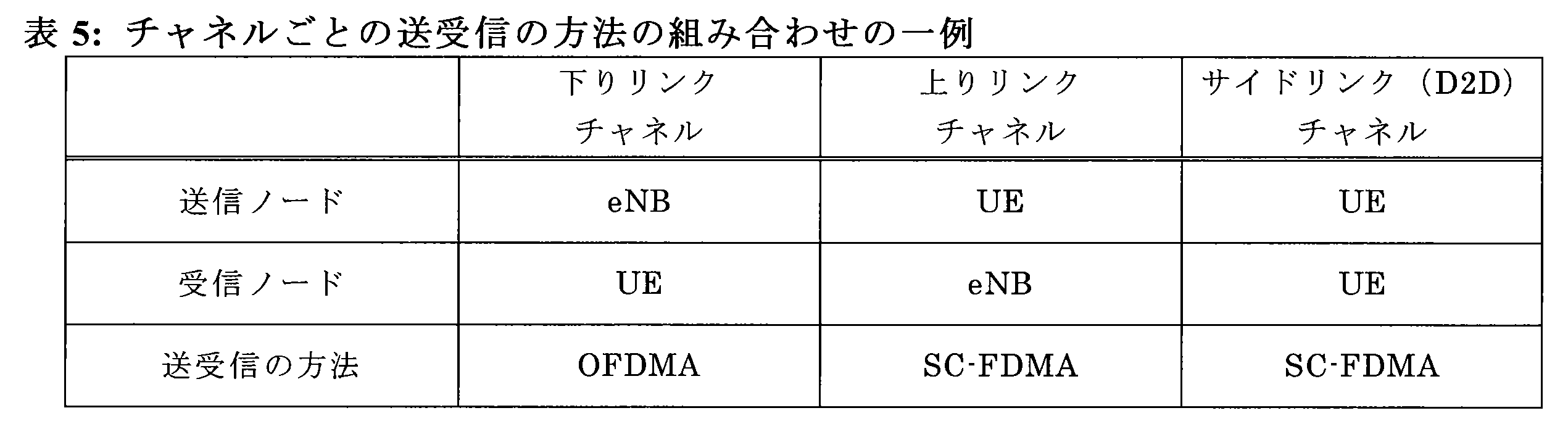
次いで、端末装置300による報知情報の受信及び送信に係る処理の一例として、特に、受信方法及び送信方法の切り替えに係る処理に着目して説明する。まず、図12を参照して、端末装置300が、基地局200または他の端末装置300からメッセージを報知情報として受信する場合の処理の一例について説明する。図12は、端末装置300によるメッセージの受信に係る処理の流れの一例を示したフローチャートである。
次いで、端末装置300の機能構成の一例について、特に、情報の受信及び送信に係る構成に着目して、受信方法及び送信方法に応じてそれぞれ説明する。
まず、図14及び図15を参照して、端末装置300が基地局200から情報を受信する場合等のような、OFMDAに基づく情報の受信に着目した、端末装置300の機能構成の一例について説明する。図14及び図15は、端末装置300による情報の受信に係る機能構成の一例を示したブロック図であり、OFDMAに基づく情報の受信に着目した場合の一例を示している。
次いで、図16及び図17を参照して、端末装置300が他の端末装置300に情報を送信する場合等のような、SC-FMDAに基づく情報の送信に着目した、端末装置300の機能構成の一例について説明する。図16及び図17は、端末装置300による情報の送信に係る機能構成の一例を示したブロック図であり、SC-FDMAに基づく情報の送信に着目した場合の一例を示している。
次いで、図18及び図19を参照して、端末装置300が他の端末装置300から情報を受信する場合等のような、SC-FMDAに基づく情報の受信に着目した、端末装置300の機能構成の一例について説明する。図18及び図19は、端末装置300による情報の受信に係る機能構成の一例を示したブロック図であり、SC-FDMAに基づく情報の受信に着目した場合の一例を示している。
次いで、端末装置300間において報知情報(即ち、メッセージ)を複数回ホップさせる(即ち、マルチホップさせる)ことで、当該報知情報が到達する範囲をさらに広げるための仕組みの一例について説明する。なお、本説明では、特徴的な部分をよりわかりやすくするために、基地局200から配信されたメッセージが、当該端末装置300aから端末装置300bに再配信され、さらに、端末装置300bが、端末装置300cに当該メッセージを再配信する場合の例に着目して説明する。
まず、図20を参照して、基地局200から配信された報知情報を、端末装置300間においてマルチホップさせる場合のシーケンスの一例について説明する。図20は、基地局200から配信された報知情報を、端末装置300間においてマルチホップさせる場合における処理フローの一例を示したシーケンス図である。なお、図20に示す例において、基地局200より上位のエンティティ間における通信の処理フローについては、図8を参照して説明した例と同様のため図示を省略している。また、図20において、参照符号S501~S515で示された処理は、図8に示す例において参照符号S207~S215、及びS225で示された処理と実質的に同様のため、詳細な説明は省略し、端末装置300bの動作に着目して説明する。
次いで、端末装置300間において報知情報をマルチホップさせる回数(即ち、ホップ数)を制限するための仕組みの一例について説明する。

次いで、端末装置300間において報知情報をマルチホップさせる場合における、端末装置300の一連の処理の流れの一例について説明する。なお、本説明では、特徴的な部分をよりわかりやすくするために、図20に示す例における、端末装置300bの動作に着目して説明する。例えば、図21は、端末装置300間において報知情報をマルチホップさせる場合における、端末装置300の一連の処理の流れの一例を示したフローチャートであり、図10に示した例に対して、マルチホップに関する制御を追加した一例である。そこで、本説明では、図21に示す例について、図10に示す例と異なる部分に着目して説明し、図10に示す例と実質的に同様の部分については詳細な説明は省略する。
次いで、端末装置300が、報知情報を受信したシステム(例えば、当該基地局200配下のシステム(セルラーシステム))とは異なる他の通信システムを利用することで、他の端末装置300に当該メッセージを再配信する場合の一例について説明する。なお、本説明では、特徴的な部分をよりわかりやすくするために、基地局200から端末装置300aに対してメッセージが配信され、当該端末装置300aが、セルラーシステムとは異なる他の通信システムを介して、当該メッセージを他の端末装置300bに再配信する場合の例に着目して説明する。
まず、図23を参照して、端末装置300が、報知情報を受信したシステムとは異なる通信システムを利用して他の端末装置300に再配信する場合のシーケンスの一例について説明する。図23は、端末装置300が、報知情報を受信したシステムとは異なる通信システムを利用して他の端末装置300に再配信する場合における処理フローの一例を示したシーケンス図である。図23に示す例では、端末装置300aは、基地局200から受信したメッセージを、例えば、WLAN(Wireless LAN(Local Area Network))、Wi-Fi(登録商標)、Bluetooth(登録商標)等のような、セルラーシステムとは異なる通信システムを介して接続された端末装置300bにメッセージを再配信する。なお、図23に示す例において、基地局200より上位のエンティティ間における通信の処理フローについては、図8を参照して説明した例と同様のため図示を省略している。また、図23において、参照符号S701~S715で示された処理は、図8に示す例において参照符号S207~S215で示された処理と実質的に同様のため、詳細な説明は省略し、端末装置300aの動作に着目して説明する。
次いで、端末装置300が、報知情報を受信したシステムとは異なる通信システムを利用して他の端末装置300に再配信する場合における、端末装置300の一連の処理の流れの一例について説明する。なお、本説明では、特徴的な部分をよりわかりやすくするために、図23に示す例における、端末装置300aの動作に着目して説明する。例えば、図24は、端末装置300が、報知情報を受信したシステムとは異なる通信システムを利用して他の端末装置300に再配信する場合における、端末装置300の一連の処理の流れの一例を示したフローチャートである。
次いで、端末装置300が、報知情報を受信したシステムとは異なる通信システムを利用して他の端末装置300に再配信する場合における、報知情報のプロトコルフォーマットの変換例について説明する。なお、本説明では、受信された報知情報がETWS及びCMASのそれぞれの場合を例として説明する。
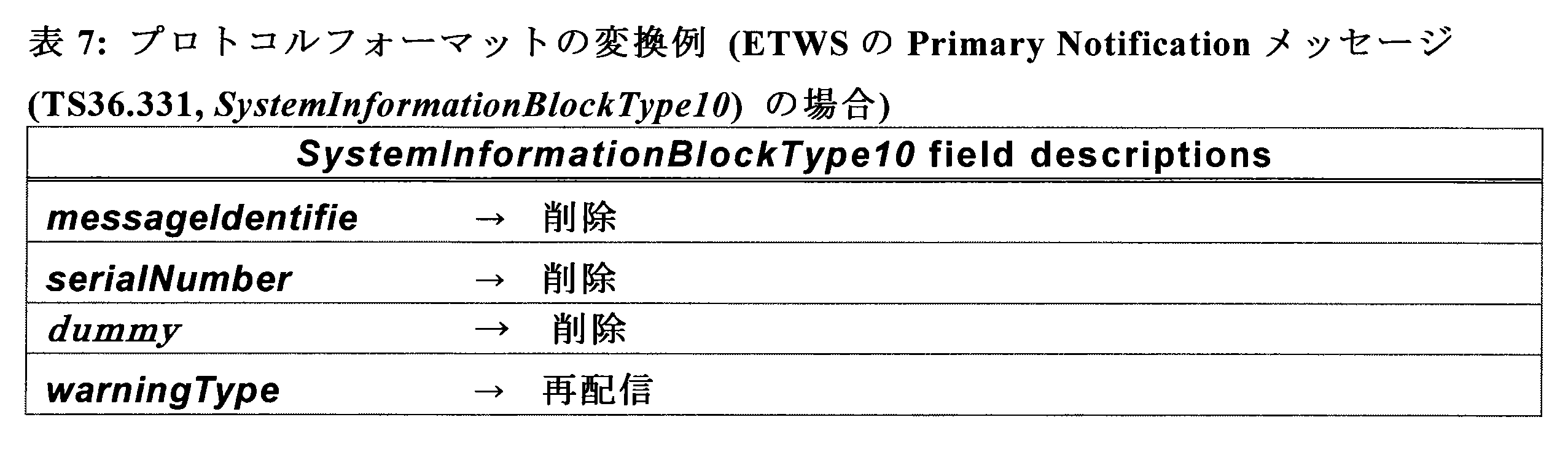
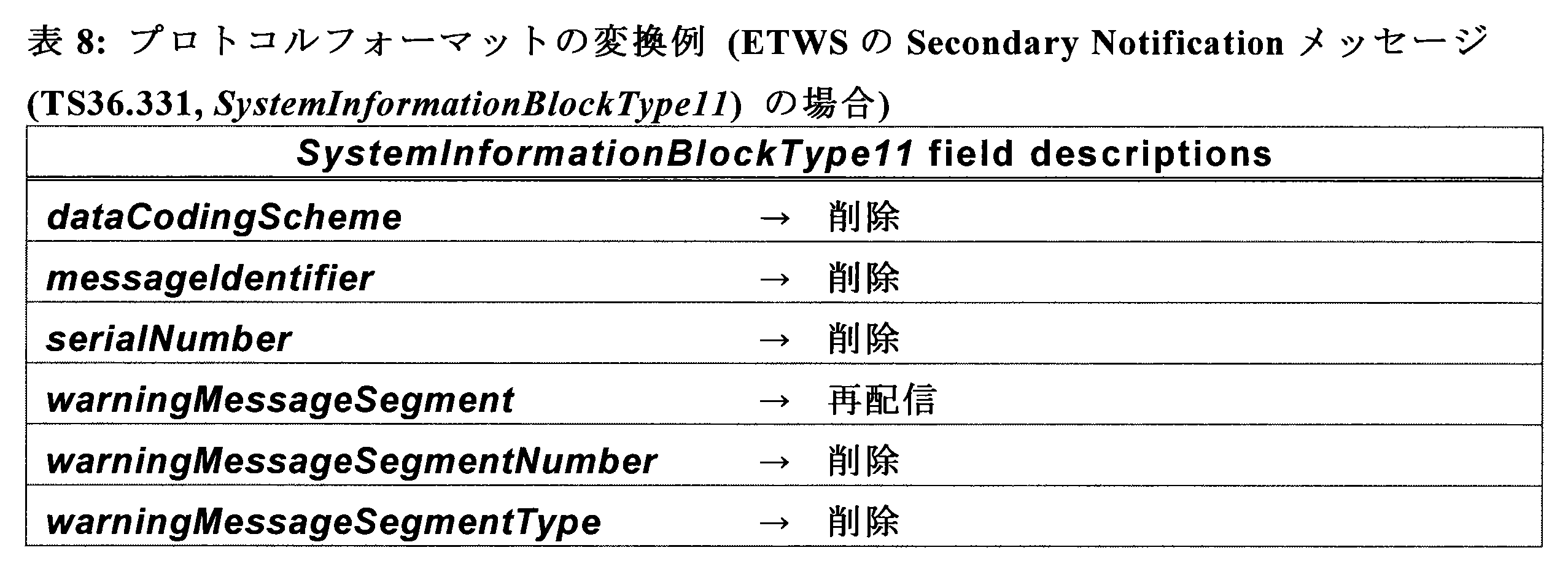
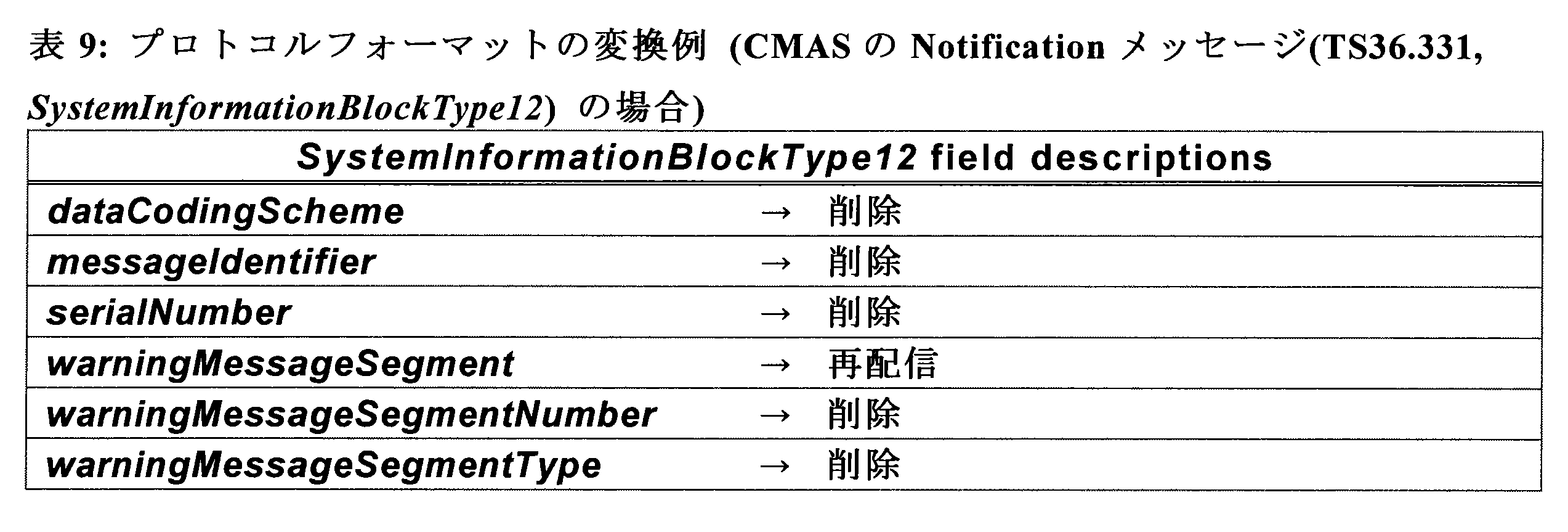
次いで、基地局200または他の端末装置300から、緊急情報等のような所定の種別のメッセージの配信(または、再配信)を受けた端末装置300が、当該メッセージの内容に応じて所定の動作制御を行う場合の一例について説明する。
まず、図25を参照して、端末装置300が、緊急情報等のような所定の種別のメッセージを受信した場合に、当該メッセージの内容に応じて所定の動作制御を実行する場合のシーケンスの一例について説明する。図25は、端末装置300が、緊急情報等のような所定の種別のメッセージを受信した場合に、当該メッセージの内容に応じて所定の動作制御を実行する場合の処理フローの一例を示したシーケンス図である。なお、図25に示す例において、基地局200より上位のエンティティ間における通信の処理フローについては、図8を参照して説明した例と同様のため図示を省略している。また、図25において、参照符号S801~S815で示された処理は、図8に示す例において参照符号S207~S215で示された処理と実質的に同様のため、詳細な説明は省略し、端末装置300a及び300bの動作に着目して説明する。
次いで、図26を参照して、緊急情報の配信を受けた端末装置300による、当該緊急情報の内容に応じた動作制御の一連の処理の流れの一例について説明する。図26は、端末装置300による、緊急情報の内容に応じた動作制御の一連の処理の流れの一例を示したフローチャートである。
次いで、端末装置300による動作制御の一例として、緊急情報の配信を受けた端末装置300が、当該緊急情報で示された事象に関する情報を、ナビゲーション装置等が表示する地図情報上に提示する場合の動作の一例について説明する。
次いで、端末装置300による動作制御の一例として、緊急情報の配信を受けた端末装置300が、注意エリア内に自身が位置するか否かを判定し、判定結果に応じて、ユーザに対して注意喚起のための通知を行う場合の処理の一例について説明する。例えば、図30は、端末装置300が、注意エリア内に位置するか否かに応じてユーザへの通知を実行する場合における一連の処理の流れの一例を示したフローチャートである。
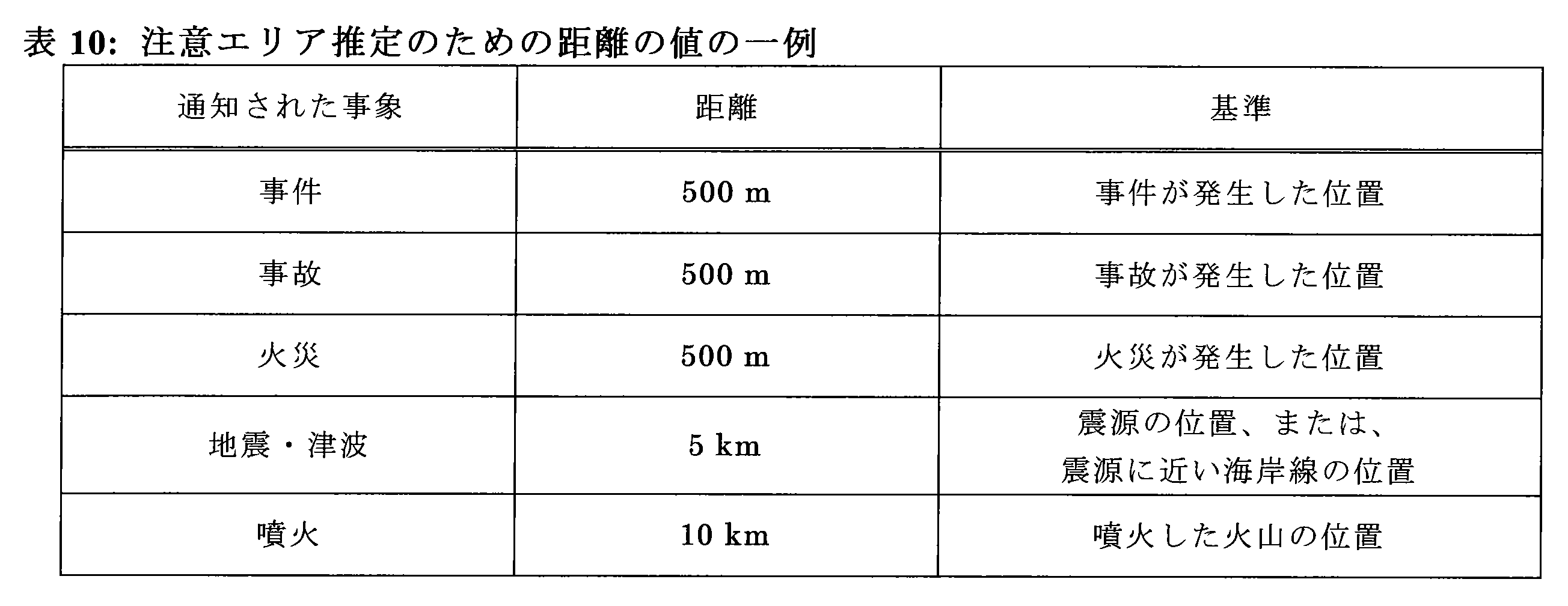
次いで、端末装置300による動作制御の一例として、緊急情報の配信を受けた端末装置300が、自身に関連付けられた車両の動作を制御する場合の処理の一例について説明する。

次いで、図31を参照して、端末装置300が、配信されたメッセージの内容に応じてユーザに情報を報知する動作の一例について説明する。図31は、端末装置300からユーザへの情報の報知態様の一例について説明するための説明図である。
本開示に係る技術は、様々な製品へ応用可能である。例えば、通信制御装置100は、タワーサーバ、ラックサーバ、又はブレードサーバなどのいずれかの種類のサーバとして実現されてもよい。また、通信制御装置100の少なくとも一部の構成要素は、サーバに搭載されるモジュール(例えば、1つのダイで構成される集積回路モジュール、又はブレードサーバのスロットに挿入されるカード若しくはブレード)において実現されてもよい。
図32は、本開示に係る技術が適用され得るサーバ700の概略的な構成の一例を示すブロック図である。サーバ700は、プロセッサ701、メモリ702、ストレージ703、ネットワークインタフェース704及びバス706を備える。
(第1の応用例)
図33は、本開示に係る技術が適用され得るeNBの概略的な構成の第1の例を示すブロック図である。eNB800は、1つ以上のアンテナ810、及び基地局装置820を有する。各アンテナ810及び基地局装置820は、RFケーブルを介して互いに接続され得る。
図34は、本開示に係る技術が適用され得るeNBの概略的な構成の第2の例を示すブロック図である。eNB830は、1つ以上のアンテナ840、基地局装置850、及びRRH860を有する。各アンテナ840及びRRH860は、RFケーブルを介して互いに接続され得る。また、基地局装置850及びRRH860は、光ファイバケーブルなどの高速回線で互いに接続され得る。
(第1の応用例)
図35は、本開示に係る技術が適用され得るスマートフォン900の概略的な構成の一例を示すブロック図である。スマートフォン900は、プロセッサ901、メモリ902、ストレージ903、外部接続インタフェース904、カメラ906、センサ907、マイクロフォン908、入力デバイス909、表示デバイス910、スピーカ911、無線通信インタフェース912、1つ以上のアンテナスイッチ915、1つ以上のアンテナ916、バス917、バッテリー918及び補助コントローラ919を備える。
図36は、本開示に係る技術が適用され得るカーナビゲーション装置920の概略的な構成の一例を示すブロック図である。カーナビゲーション装置920は、プロセッサ921、メモリ922、GPS(Global Positioning System)モジュール924、センサ925、データインタフェース926、コンテンツプレーヤ927、記憶媒体インタフェース928、入力デバイス929、表示デバイス930、スピーカ931、無線通信インタフェース933、1つ以上のアンテナスイッチ936、1つ以上のアンテナ937及びバッテリー938を備える。
以上説明したように、本実施形態に係る通信システム1において、端末装置300は、基地局200から報知情報(即ち、メッセージ)の配信を受けると、当該報知情報が所定の種別の情報(例えば、緊急情報等)を含む場合には、当該報知情報を他の端末装置300に再配信する。このとき、端末装置300は、基地局200配下のシステムとは異なる他のシステムを介して、他の端末装置300に報知情報を再配信してもよい。また、再配信される報知情報は、端末装置300間においてマルチホップされてもよい。
(1)
無線通信を行う通信部と、
前記無線通信を介して第1の装置から報知情報を取得する取得部と、
取得された前記報知情報が所定の種別の情報を含む場合に、当該報知情報が、前記通信部から所定の通信範囲内に位置する第2の装置に送信されるように制御する通信制御部と、
を備える、装置。
(2)
前記第1の装置は、基地局であり、
前記取得部は、前記基地局から無線リソースを示す情報を取得し、
前記通信制御部は、報知情報が、前記通信部から前記無線リソースを介して前記第2の装置に送信されるように制御する、
前記(1)に記載の装置。
(3)
前記取得部は、前記基地局に対して前記無線リソースの割り当てが依頼された後に、当該基地局から前記無線リソースを示す情報を取得する、前記(2)に記載の装置。
(4)
前記通信制御部は、前記第1の装置との間の通信で使用される通信方式とは異なる他の通信方式に基づき、前記報知情報が、前記第2の装置に送信されるように制御する、前記(1)~(3)のいずれか一項に記載の装置。
(5)
前記通信制御部は、前記第1の装置との間の通信で使用される無線リソースとは異なる他の無線リソースを介して、前記報知情報が、前記第2の装置に送信されるように制御する、前記(1)~(4)のいずれか一項に記載の装置。
(6)
前記通信制御部は、あらかじめ決められた無線リソースを介して、前記報知情報が、前記第2の装置に送信されるように制御する、前記(1)に記載の装置。
(7)
前記通信制御部は、前記第1の装置が属する通信システムとは異なる他の通信システムに属する前記第2の装置に対して、前記報知情報が送信されるように制御する、前記(1)~(6)のいずれか一項に記載の装置。
(8)
前記第1の装置は、端末であり、
前記通信制御部は、基地局から送信された前記報知情報が前記取得部に取得されるまでに中継された前記端末の数に応じて、前記第2の装置への当該報知情報の送信を制御する、前記(1)に記載の装置。
(9)
無線通信を行う通信部と、
第1の装置に対して配信される報知情報を、当該第1の装置が第2の装置に再配信するための無線リソースを示す情報が、前記通信部から前記第1の装置に通知されるように制御する通信制御部と、
を備える、装置。
(10)
前記通信制御部は、所定の通信範囲内に位置する前記第1の装置に対して、前記無線リソースを示す情報が通知されるように制御する、前記(9)に記載の装置。
(11)
前記通信制御部は、
前記報知情報が、前記第1の装置に対して送信されるように制御し、
前記報知情報が送信された当該第1の装置に対して、前記無線リソースを示す情報が通知されるように制御する、前記(9)に記載の装置。
(12)
前記通信制御部は、前記報知情報が送信された前記第1の装置から前記無線リソースの割り当てに関する依頼を受けた後に、当該第1の装置に対して、前記無線リソースを示す情報が通知されるように制御する、前記(11)に記載の装置。
(13)
無線通信を行う通信部と、
前記無線通信を介して外部装置から報知情報を取得する取得部と、
取得された前記報知情報が所定の種別の情報を含む場合に、前記報知情報の内容に応じて、車両及びナビゲーション装置のうち少なくともいずれかに関する動作を制御する制御部と、
を備える、装置。
(14)
前記報知情報は、発生した事象に関する情報を含み、
前記制御部は、前記事象に関する情報が提示されるように、前記ナビゲーション装置に関する動作を制御する、前記(13)に記載の装置。
(15)
前記報知情報は、前記事象が発生した位置に関する情報を含み、
前記制御部は、地図情報上に、前記事象が発生した位置に関する情報が提示されるように、前記ナビゲーション装置に関する動作を制御する、前記(14)に記載の装置。
(16)
前記制御部は、前記事象が発生した位置を、前記地図情報上の位置に関連付けて提示する、前記(15)に記載の装置。
(17)
前記制御部は、前記地図情報上に、前記事象が発生した位置の方角を示す情報を提示する、前記(15)に記載の装置。
(18)
前記報知情報は、発生した事象に関する情報を含み、
前記制御部は、前記事象に関する情報に応じて、前記車両の動作を制御する、前記(13)~(17)のいずれか一項に記載の装置。
(19)
無線通信を行うことと、
前記無線通信を介して第1の装置から報知情報を取得することと、
プロセッサが、取得された前記報知情報が所定の種別の情報を含む場合に、当該報知情報が、所定の通信範囲内に位置する第2の装置に送信されるように制御することと、
を含む、方法。
(20)
無線通信を行うことと、
プロセッサが、第1の装置に対して配信される報知情報を、当該第1の装置が第2の装置に再配信するための無線リソースを示す情報が、前記第1の装置に通知されるように制御することと、
を含む、方法。
(21)
無線通信を行うことと、
前記無線通信を介して外部装置から報知情報を取得することと、
プロセッサが、取得された前記報知情報が所定の種別の情報を含む場合に、前記報知情報の内容に応じて、車両及びナビゲーション装置の少なくともいずれかに関する動作を制御することと、
を含む、方法。
(22)
コンピュータに、
無線通信を行うことと、
前記無線通信を介して外部装置から報知情報を取得することと、
取得された前記報知情報が所定の種別の情報を含む場合に、前記報知情報の内容に応じて、車両及びナビゲーション装置の少なくともいずれかに関する動作を制御することと、
を実行させる、プログラム。
100 通信制御装置
110 通信部
120 記憶部
130 制御部
200 基地局
210 無線通信部
220 ネットワーク通信部
230 記憶部
240 制御部
300 端末装置
300 基地局
310 無線通信部
320 記憶部
330 制御部
340 報知部
390 車両部
Claims (22)
- 無線通信を行う通信部と、
前記無線通信を介して第1の装置から報知情報を取得する取得部と、
取得された前記報知情報が所定の種別の情報を含む場合に、当該報知情報が、前記通信部から所定の通信範囲内に位置する第2の装置に送信されるように制御する通信制御部と、
を備える、装置。 - 前記第1の装置は、基地局であり、
前記取得部は、前記基地局から無線リソースを示す情報を取得し、
前記通信制御部は、報知情報が、前記通信部から前記無線リソースを介して前記第2の装置に送信されるように制御する、
請求項1に記載の装置。 - 前記取得部は、前記基地局に対して前記無線リソースの割り当てが依頼された後に、当該基地局から前記無線リソースを示す情報を取得する、請求項2に記載の装置。
- 前記通信制御部は、前記第1の装置との間の通信で使用される通信方式とは異なる他の通信方式に基づき、前記報知情報が、前記第2の装置に送信されるように制御する、請求項1に記載の装置。
- 前記通信制御部は、前記第1の装置との間の通信で使用される無線リソースとは異なる他の無線リソースを介して、前記報知情報が、前記第2の装置に送信されるように制御する、請求項1に記載の装置。
- 前記通信制御部は、あらかじめ決められた無線リソースを介して、前記報知情報が、前記第2の装置に送信されるように制御する、請求項1に記載の装置。
- 前記通信制御部は、前記第1の装置が属する通信システムとは異なる他の通信システムに属する前記第2の装置に対して、前記報知情報が送信されるように制御する、請求項1に記載の装置。
- 前記第1の装置は、端末であり、
前記通信制御部は、基地局から送信された前記報知情報が前記取得部に取得されるまでに中継された前記端末の数に応じて、前記第2の装置への当該報知情報の送信を制御する、請求項1に記載の装置。 - 無線通信を行う通信部と、
第1の装置に対して配信される報知情報を、当該第1の装置が第2の装置に再配信するための無線リソースを示す情報が、前記通信部から前記第1の装置に通知されるように制御する通信制御部と、
を備える、装置。 - 前記通信制御部は、所定の通信範囲内に位置する前記第1の装置に対して、前記無線リソースを示す情報が通知されるように制御する、請求項9に記載の装置。
- 前記通信制御部は、
前記報知情報が、前記第1の装置に対して送信されるように制御し、
前記報知情報が送信された当該第1の装置に対して、前記無線リソースを示す情報が通知されるように制御する、請求項9に記載の装置。 - 前記通信制御部は、前記報知情報が送信された前記第1の装置から前記無線リソースの割り当てに関する依頼を受けた後に、当該第1の装置に対して、前記無線リソースを示す情報が通知されるように制御する、請求項11に記載の装置。
- 無線通信を行う通信部と、
前記無線通信を介して外部装置から報知情報を取得する取得部と、
取得された前記報知情報が所定の種別の情報を含む場合に、前記報知情報の内容に応じて、車両及びナビゲーション装置のうち少なくともいずれかに関する動作を制御する制御部と、
を備える、装置。 - 前記報知情報は、発生した事象に関する情報を含み、
前記制御部は、前記事象に関する情報が提示されるように、前記ナビゲーション装置に関する動作を制御する、請求項13に記載の装置。 - 前記報知情報は、前記事象が発生した位置に関する情報を含み、
前記制御部は、地図情報上に、前記事象が発生した位置に関する情報が提示されるように、前記ナビゲーション装置に関する動作を制御する、請求項14に記載の装置。 - 前記制御部は、前記事象が発生した位置を、前記地図情報上の位置に関連付けて提示する、請求項15に記載の装置。
- 前記制御部は、前記地図情報上に、前記事象が発生した位置の方角を示す情報を提示する、請求項15に記載の装置。
- 前記報知情報は、発生した事象に関する情報を含み、
前記制御部は、前記事象に関する情報に応じて、前記車両の動作を制御する、請求項13に記載の装置。 - 無線通信を行うことと、
前記無線通信を介して第1の装置から報知情報を取得することと、
プロセッサが、取得された前記報知情報が所定の種別の情報を含む場合に、当該報知情報が、所定の通信範囲内に位置する第2の装置に送信されるように制御することと、
を含む、方法。 - 無線通信を行うことと、
プロセッサが、第1の装置に対して配信される報知情報を、当該第1の装置が第2の装置に再配信するための無線リソースを示す情報が、前記第1の装置に通知されるように制御することと、
を含む、方法。 - 無線通信を行うことと、
前記無線通信を介して外部装置から報知情報を取得することと、
プロセッサが、取得された前記報知情報が所定の種別の情報を含む場合に、前記報知情報の内容に応じて、車両及びナビゲーション装置の少なくともいずれかに関する動作を制御することと、
を含む、方法。 - コンピュータに、
無線通信を行うことと、
前記無線通信を介して外部装置から報知情報を取得することと、
取得された前記報知情報が所定の種別の情報を含む場合に、前記報知情報の内容に応じて、車両及びナビゲーション装置の少なくともいずれかに関する動作を制御することと、
を実行させる、プログラム。
Priority Applications (3)
| Application Number | Priority Date | Filing Date | Title |
|---|---|---|---|
| US15/769,858 US20180310158A1 (en) | 2015-11-13 | 2016-08-24 | Device and method |
| JP2017550004A JPWO2017081907A1 (ja) | 2015-11-13 | 2016-08-24 | 装置及び方法 |
| EP16863871.6A EP3376785A4 (en) | 2015-11-13 | 2016-08-24 | Device and method |
Applications Claiming Priority (2)
| Application Number | Priority Date | Filing Date | Title |
|---|---|---|---|
| JP2015-222689 | 2015-11-13 | ||
| JP2015222689 | 2015-11-13 |
Publications (1)
| Publication Number | Publication Date |
|---|---|
| WO2017081907A1 true WO2017081907A1 (ja) | 2017-05-18 |
Family
ID=58696004
Family Applications (1)
| Application Number | Title | Priority Date | Filing Date |
|---|---|---|---|
| PCT/JP2016/074677 Ceased WO2017081907A1 (ja) | 2015-11-13 | 2016-08-24 | 装置及び方法 |
Country Status (4)
| Country | Link |
|---|---|
| US (1) | US20180310158A1 (ja) |
| EP (1) | EP3376785A4 (ja) |
| JP (1) | JPWO2017081907A1 (ja) |
| WO (1) | WO2017081907A1 (ja) |
Cited By (5)
| Publication number | Priority date | Publication date | Assignee | Title |
|---|---|---|---|---|
| JP2019082932A (ja) * | 2017-10-31 | 2019-05-30 | 富士通コネクテッドテクノロジーズ株式会社 | 通知方法、通信端末、及び警報通知システム |
| WO2019230434A1 (ja) * | 2018-05-29 | 2019-12-05 | 株式会社村田製作所 | 情報提供電子タグ、情報提供システム、情報提供方法 |
| JP2020036204A (ja) * | 2018-08-30 | 2020-03-05 | 沖電気工業株式会社 | 無線通信端末、緊急速報通知システム、緊急速報通知方法、及びプログラム |
| WO2022254658A1 (ja) * | 2021-06-03 | 2022-12-08 | 三菱電機株式会社 | 通信システム、携帯端末、プログラム及び通信方法 |
| WO2025211333A1 (ja) * | 2024-04-02 | 2025-10-09 | トヨタ自動車株式会社 | 無線通信方法、ユーザ端末、および基地局 |
Families Citing this family (4)
| Publication number | Priority date | Publication date | Assignee | Title |
|---|---|---|---|---|
| JP6765063B2 (ja) * | 2016-10-27 | 2020-10-07 | パナソニックIpマネジメント株式会社 | 遠隔型自動走行システム、無線通信方法、移動体装置及びプログラム |
| JP2020537373A (ja) * | 2017-09-15 | 2020-12-17 | オッポ広東移動通信有限公司Guangdong Oppo Mobile Telecommunications Corp., Ltd. | 搬送波選択方法、端末装置、及びコンピュータ記憶媒体 |
| US11284376B2 (en) * | 2018-08-17 | 2022-03-22 | At&T Intellectual Property I, L.P. | Distributed control information for multiple party communications for 5G or other next generation network |
| JP7238656B2 (ja) * | 2019-07-11 | 2023-03-14 | トヨタ自動車株式会社 | 情報処理装置、及び、情報処理方法 |
Citations (5)
| Publication number | Priority date | Publication date | Assignee | Title |
|---|---|---|---|---|
| JP2002288787A (ja) * | 2001-03-28 | 2002-10-04 | Denso Corp | 緊急情報報知システム、当該システムに用いられる車載側装置、プログラム及び記録媒体 |
| JP2006318003A (ja) * | 2005-05-10 | 2006-11-24 | Matsushita Electric Ind Co Ltd | 車両用地震警報装置およびそのプログラム |
| JP2008244813A (ja) * | 2007-03-27 | 2008-10-09 | Ntt Docomo Inc | 移動通信端末、無線通信方法及び移動通信システム |
| WO2014061198A1 (ja) * | 2012-10-15 | 2014-04-24 | 日本電気株式会社 | 交通情報配信システム、セルラ通信システム、通信端末、及び交通情報サーバ |
| WO2015046155A1 (ja) * | 2013-09-27 | 2015-04-02 | 京セラ株式会社 | 通信制御方法 |
Family Cites Families (12)
| Publication number | Priority date | Publication date | Assignee | Title |
|---|---|---|---|---|
| US8737924B2 (en) * | 2010-08-12 | 2014-05-27 | Mediatek Inc. | Method to trigger in-device coexistence interference mitigation in mobile cellular systems |
| US9185217B2 (en) * | 2011-11-01 | 2015-11-10 | GreatCall, Inc. | Emergency mobile notification handling |
| US9173070B2 (en) * | 2012-04-24 | 2015-10-27 | At&T Intellectual Property I, L.P. | Receiving an emergency alert message via a broadcast data channel |
| WO2014121507A1 (zh) * | 2013-02-08 | 2014-08-14 | 华为技术有限公司 | 设备到设备通信方法、终端和网络设备 |
| US10034147B2 (en) * | 2013-09-26 | 2018-07-24 | Coherent Logix, Incorporated | Next generation broadcast system and method |
| US10187885B2 (en) * | 2014-02-10 | 2019-01-22 | Lg Electronics Inc. | Method and device for transmitting frame in wireless LAN |
| JP6108554B2 (ja) * | 2014-02-25 | 2017-04-05 | 日本電信電話株式会社 | 無線通信装置及び無線通信方法 |
| CN106465369B (zh) * | 2014-05-06 | 2019-11-12 | Lg电子株式会社 | 在无线通信系统中由终端执行的装置对装置(d2d)操作的方法及使用该方法的终端 |
| US20170171690A1 (en) * | 2014-07-20 | 2017-06-15 | Lg Electronics Inc. | Method for terminal-condition-based d2d communication, and apparatus therefor in wireless communication system |
| JP6409169B2 (ja) * | 2014-08-22 | 2018-10-24 | 富士通コネクテッドテクノロジーズ株式会社 | 無線端末、無線局、無線通信システム、および無線通信方法 |
| US10021620B2 (en) * | 2015-02-10 | 2018-07-10 | Qualcomm Incorporated | Relay signaling between UE and network |
| US10477620B2 (en) * | 2015-08-20 | 2019-11-12 | Intel IP Corporation | Machine type communication relaying |
-
2016
- 2016-08-24 EP EP16863871.6A patent/EP3376785A4/en not_active Withdrawn
- 2016-08-24 US US15/769,858 patent/US20180310158A1/en not_active Abandoned
- 2016-08-24 WO PCT/JP2016/074677 patent/WO2017081907A1/ja not_active Ceased
- 2016-08-24 JP JP2017550004A patent/JPWO2017081907A1/ja active Pending
Patent Citations (5)
| Publication number | Priority date | Publication date | Assignee | Title |
|---|---|---|---|---|
| JP2002288787A (ja) * | 2001-03-28 | 2002-10-04 | Denso Corp | 緊急情報報知システム、当該システムに用いられる車載側装置、プログラム及び記録媒体 |
| JP2006318003A (ja) * | 2005-05-10 | 2006-11-24 | Matsushita Electric Ind Co Ltd | 車両用地震警報装置およびそのプログラム |
| JP2008244813A (ja) * | 2007-03-27 | 2008-10-09 | Ntt Docomo Inc | 移動通信端末、無線通信方法及び移動通信システム |
| WO2014061198A1 (ja) * | 2012-10-15 | 2014-04-24 | 日本電気株式会社 | 交通情報配信システム、セルラ通信システム、通信端末、及び交通情報サーバ |
| WO2015046155A1 (ja) * | 2013-09-27 | 2015-04-02 | 京セラ株式会社 | 通信制御方法 |
Non-Patent Citations (2)
| Title |
|---|
| LG ELECTRONICS: "Resource Management for D2D Communications", 3GPP TSG RAN WG1 MEETING #74 R1-133385, pages 2, XP050716499 * |
| See also references of EP3376785A4 * |
Cited By (8)
| Publication number | Priority date | Publication date | Assignee | Title |
|---|---|---|---|---|
| JP2019082932A (ja) * | 2017-10-31 | 2019-05-30 | 富士通コネクテッドテクノロジーズ株式会社 | 通知方法、通信端末、及び警報通知システム |
| JP7053099B2 (ja) | 2017-10-31 | 2022-04-12 | Fcnt株式会社 | 通知方法、通信端末、及び警報通知システム |
| WO2019230434A1 (ja) * | 2018-05-29 | 2019-12-05 | 株式会社村田製作所 | 情報提供電子タグ、情報提供システム、情報提供方法 |
| JP2020036204A (ja) * | 2018-08-30 | 2020-03-05 | 沖電気工業株式会社 | 無線通信端末、緊急速報通知システム、緊急速報通知方法、及びプログラム |
| WO2022254658A1 (ja) * | 2021-06-03 | 2022-12-08 | 三菱電機株式会社 | 通信システム、携帯端末、プログラム及び通信方法 |
| JPWO2022254658A1 (ja) * | 2021-06-03 | 2022-12-08 | ||
| JP7752685B2 (ja) | 2021-06-03 | 2025-10-10 | 三菱電機株式会社 | 通信システム、携帯端末、プログラム及び通信方法 |
| WO2025211333A1 (ja) * | 2024-04-02 | 2025-10-09 | トヨタ自動車株式会社 | 無線通信方法、ユーザ端末、および基地局 |
Also Published As
| Publication number | Publication date |
|---|---|
| EP3376785A4 (en) | 2018-11-14 |
| US20180310158A1 (en) | 2018-10-25 |
| JPWO2017081907A1 (ja) | 2018-08-30 |
| EP3376785A1 (en) | 2018-09-19 |
Similar Documents
| Publication | Publication Date | Title |
|---|---|---|
| WO2017081907A1 (ja) | 装置及び方法 | |
| JP6194896B2 (ja) | 通信制御装置、通信制御方法、端末装置及びプログラム | |
| JP2021514550A (ja) | Nr v2xのサイドリンク制御情報の送信 | |
| WO2020084879A1 (ja) | 無線端末、無線アクセスネットワークノード、及びこれらの方法 | |
| JP6947860B2 (ja) | 接続確立方法及び装置 | |
| JP2021514549A (ja) | Nr v2xの2ステップsci送信 | |
| EP3282719A1 (en) | Method and device for determining and using d2d relay node | |
| KR102892289B1 (ko) | Nr v2x에서 릴레이를 위한 전송 자원을 요청하는 방법 및 장치 | |
| KR20160131740A (ko) | 차량 서비스를 위한 자원 할당 장치 및 방법 | |
| US20200092705A1 (en) | Communication control device, communication control method, terminal device, and information processing device | |
| EP4255103A3 (en) | Device and method for service subscription via e2 interface in radio access network communication system | |
| JP2019510396A (ja) | リソース設定を実現する方法及び装置 | |
| WO2016163206A1 (ja) | 端末装置、無線通信装置、無線通信方法及びコンピュータプログラム | |
| CN109565647B (zh) | 车联网设备之间的信息传输方法、装置及系统 | |
| KR102826690B1 (ko) | Nr v2x에서 s-ssb를 전송하는 방법 및 장치 | |
| CN106211240B (zh) | 提高无线局域网wlan并发处理能力的方法、装置及系统 | |
| JP2022528161A (ja) | Nr v2xにおける位置情報を送信する方法及び装置 | |
| JP6918226B2 (ja) | Nr v2xにおけるbwpベースの通信を実行する方法及び装置 | |
| JP2022520433A (ja) | Dciをベースにlte sl通信を行う方法や装置 | |
| KR20230007468A (ko) | 사이드링크를 지원하는 무선통신시스템에서 vru가 안전 메시지를 전송하는 방법 및 이를 위한 장치 | |
| CN107041001B (zh) | 通信资源的确定方法及装置 | |
| JP2022520950A (ja) | Lteサイドリンク通信を制御するdci | |
| US20250048238A1 (en) | Wireless communication method and network device | |
| US12177818B2 (en) | Method for transmitting sidelink signal in wireless communication system | |
| CN104936187B (zh) | 用于设备到设备信号传输的资源分配方法和装置 |
Legal Events
| Date | Code | Title | Description |
|---|---|---|---|
| 121 | Ep: the epo has been informed by wipo that ep was designated in this application |
Ref document number: 16863871 Country of ref document: EP Kind code of ref document: A1 |
|
| ENP | Entry into the national phase |
Ref document number: 2017550004 Country of ref document: JP Kind code of ref document: A |
|
| WWE | Wipo information: entry into national phase |
Ref document number: 15769858 Country of ref document: US |
|
| NENP | Non-entry into the national phase |
Ref country code: DE |
|
| WWE | Wipo information: entry into national phase |
Ref document number: 2016863871 Country of ref document: EP |