WO2017081912A1 - 運搬車両 - Google Patents
運搬車両 Download PDFInfo
- Publication number
- WO2017081912A1 WO2017081912A1 PCT/JP2016/075626 JP2016075626W WO2017081912A1 WO 2017081912 A1 WO2017081912 A1 WO 2017081912A1 JP 2016075626 W JP2016075626 W JP 2016075626W WO 2017081912 A1 WO2017081912 A1 WO 2017081912A1
- Authority
- WO
- WIPO (PCT)
- Prior art keywords
- time
- engine
- waiting time
- transport vehicle
- load
- Prior art date
- Legal status (The legal status is an assumption and is not a legal conclusion. Google has not performed a legal analysis and makes no representation as to the accuracy of the status listed.)
- Ceased
Links
Images


Classifications
-
- F—MECHANICAL ENGINEERING; LIGHTING; HEATING; WEAPONS; BLASTING
- F02—COMBUSTION ENGINES; HOT-GAS OR COMBUSTION-PRODUCT ENGINE PLANTS
- F02D—CONTROLLING COMBUSTION ENGINES
- F02D29/00—Controlling engines, such controlling being peculiar to the devices driven thereby, the devices being other than parts or accessories essential to engine operation, e.g. controlling of engines by signals external thereto
- F02D29/02—Controlling engines, such controlling being peculiar to the devices driven thereby, the devices being other than parts or accessories essential to engine operation, e.g. controlling of engines by signals external thereto peculiar to engines driving vehicles; peculiar to engines driving variable pitch propellers
-
- F—MECHANICAL ENGINEERING; LIGHTING; HEATING; WEAPONS; BLASTING
- F02—COMBUSTION ENGINES; HOT-GAS OR COMBUSTION-PRODUCT ENGINE PLANTS
- F02D—CONTROLLING COMBUSTION ENGINES
- F02D41/00—Electrical control of supply of combustible mixture or its constituents
- F02D41/02—Circuit arrangements for generating control signals
- F02D41/021—Introducing corrections for particular conditions exterior to the engine
-
- B—PERFORMING OPERATIONS; TRANSPORTING
- B60—VEHICLES IN GENERAL
- B60P—VEHICLES ADAPTED FOR LOAD TRANSPORTATION OR TO TRANSPORT, TO CARRY, OR TO COMPRISE SPECIAL LOADS OR OBJECTS
- B60P1/00—Vehicles predominantly for transporting loads and modified to facilitate loading, consolidating the load, or unloading
- B60P1/04—Vehicles predominantly for transporting loads and modified to facilitate loading, consolidating the load, or unloading with a tipping movement of load-transporting element
-
- F—MECHANICAL ENGINEERING; LIGHTING; HEATING; WEAPONS; BLASTING
- F02—COMBUSTION ENGINES; HOT-GAS OR COMBUSTION-PRODUCT ENGINE PLANTS
- F02D—CONTROLLING COMBUSTION ENGINES
- F02D2200/00—Input parameters for engine control
- F02D2200/60—Input parameters for engine control said parameters being related to the driver demands or status
- F02D2200/604—Engine control mode selected by driver, e.g. to manually start particle filter regeneration or to select driving style
-
- F—MECHANICAL ENGINEERING; LIGHTING; HEATING; WEAPONS; BLASTING
- F02—COMBUSTION ENGINES; HOT-GAS OR COMBUSTION-PRODUCT ENGINE PLANTS
- F02D—CONTROLLING COMBUSTION ENGINES
- F02D2250/00—Engine control related to specific problems or objectives
- F02D2250/18—Control of the engine output torque
- F02D2250/26—Control of the engine output torque by applying a torque limit
Definitions
- the present invention relates to a transport vehicle including a dump truck, and particularly to engine control of the transport vehicle.
- Patent Document 1 discloses a method of limiting the power that can be output from the engine in accordance with the load of the work vehicle in order to reduce the fuel consumption of the work vehicle (dump truck). Yes.
- the driver selects a power mode or a standard mode as an engine output mode by a mode setting switch.
- the engine characteristics are determined by the selected output mode, and the standard mode operates at a low output because the use area of the engine is limited compared to the power mode.
- the load level of the work vehicle is judged based on the weight of the load (loading amount) and suspension pressure. If it is judged that the load is high, the engine usage area is expanded to the high output side. When it is determined that the load is low, a process for narrowing the use area of the engine to the low output side is performed. Therefore, when it is determined that the load is low, the engine output power is suppressed, so that excess power is limited and fuel consumption is reduced.
- the technique of the above document since the engine output is changed only according to the load of the work vehicle, the following problems may occur. For example, if it is determined that the engine is in a low load state in any one of the output modes and the engine output is suppressed, the fuel consumption may decrease while the traveling speed may also decrease. Since the decrease in the traveling speed leads to a decrease in the work amount of the work vehicle, the conveyance efficiency may not be improved or deteriorated. That is, the technique of the above-mentioned document has a problem that the two points of reduction in fuel consumption and improvement in conveyance efficiency cannot always be achieved.
- an object of the present invention is to provide a transport vehicle that can achieve both improved transport efficiency and reduced fuel consumption.
- the control device starts the operation after the arrival of the destination of the transport vehicle.
- a transport vehicle capable of improving both transport efficiency and reducing fuel consumption by considering work waiting time and engine load. Can provide.
- Embodiment 1 of the present invention It is a system block diagram of Embodiment 1 of the present invention. It is a control block diagram which shows the processing content of ECU7 of Embodiment 1, 3 of this invention. It is a control block diagram which shows the processing content of the engine output power command calculation part 14 of Embodiment 1, 3 of this invention. It is a flow which calculates the average engine output power upper limit (Pow_up_limit ave ) of Embodiment 1, 3 of this invention before driving
- Time_delay work waiting time
- Ne_up_limit ave average engine speed upper limit
- FIG. 1 It is a figure which shows the relationship between the work waiting time and the maximum engine power suppression rate of Embodiment 1, 3, 5, 7 of this invention.
- Pow_up_limit real the engine output power upper limit
- the maximum output of the engine is suppressed in consideration of the engine load (loading amount) and the work waiting time when the vehicle stops working, thereby improving the conveyance efficiency and reducing the fuel consumption.
- a compatible engine control device and a mine dump truck equipped with the same will be described.
- “Lading capacity ” is the total weight of the load placed on the dump truck, and varies as appropriate according to loading / unloading.
- “Work waiting time” is the waiting time until the work (loading work / unloading work) performed after arrival of the dump truck at the destination is started, and corresponds to the time from the arrival at the destination to the start of the work. To do. The travel time between destinations is not included in the work waiting time.
- “Destination” is a concept that includes not only a certain point (point) but also a certain area (surface), and “arrival to the destination” means that a dump truck (carrying vehicle) has arrived at the certain point. And a concept including both that the dump truck has entered the certain area.
- start time of the work waiting time does not need to be uniquely determined because it can change according to the conditions of the work content, location, subject, and the like. In other words, it is not always necessary to measure the work waiting time strictly based on the arrival time at the destination, and any trigger that can recognize the occurrence of the waiting time between the time after arrival at the destination and before the start of work. It is also possible to start with Similarly, the end time of the work waiting time may be appropriately determined between the end of the work and the start of traveling to the destination.
- the destinations of the dump trucks in the mine are mainly loading sites (loading sites) and dumping sites (unloading sites), and dump trucks alternate between loading sites and dumping sites.
- the dump truck performs loading work (loading work) at the loading site, travels to the dumping ground after the loading work is completed, and performs earthing work (unloading work) at the dumping site. Then, after the earth removal work is completed, the work cycle of returning to the loading site is repeated.
- the work waiting time at a dumping ground means that if the vehicle arrives at the dumping ground even though the previous car is being dumped at the dumping ground, the own vehicle will be released until the previous car is released. Can be thought of as waiting time.
- Reasons for waiting for work include the fact that the traveling speed of the host vehicle is faster than that of the previous car and that the work end time of the front car is delayed from the assumption. Does not affect.
- the work waiting time cannot reduce the time required for one work cycle.
- the own vehicle arrives within the work waiting time of the previous vehicle, there is no problem even if the arrival time at the destination is delayed by reducing the traveling speed.
- a decrease in travel speed leads to a reduction in fuel consumption.
- the conveyance efficiency is improved by reducing the fuel consumption.
- the traveling speed on the way to the destination is reduced and the arrival time at the destination is set as the work waiting time. Delay within range. Thereby, reduction of fuel consumption and improvement of conveyance efficiency are compatible.
- an example of the configuration of the transport vehicle that realizes such operations and actions will be described.
- the dump truck for a mine of this embodiment includes an engine 1 mounted in front of the vehicle body, a cargo bed (vessel) 5 mounted on the upper rear side of the vehicle body and rotatable in the vertical direction around the rear of the vehicle body, and an upper front side of the vehicle body.
- a driver's seat 6 is provided.
- a pair of left and right driven wheels 4L and 4R are disposed on the lower front side of the vehicle body, and a pair of left and right drive wheels 3L and 3R are disposed on the rear lower side of the vehicle body.
- Suspensions 84L, 84R, 83L, and 83R are mounted around the driven wheels 4L and 4R and the drive wheels 3L and 3R, respectively.
- the load amount can be detected by detecting the pressure of each suspension 84L, 84R, 83L, 83R with a sensor (load amount sensor) 93 (see FIG. 2).
- the power transmission device 2 that transmits the power of the engine 1 to the drive wheels 3L and 3R will be described.
- a preferable power transmission device 2 for example, a combination of a field winding generator, an inverter, and a traveling induction motor (traveling motor) may be mentioned.
- traveling motor traveling motor
- the rotational energy of the engine 1 is converted into electrical energy by a generator and supplied to an inverter and a travel motor.
- the traveling motor can drive the dump wheels by driving the drive wheels 3L and 3R.
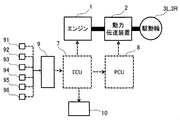
- the dump truck shown in FIG. 1 further includes an ECU (Engine Control Unit: Engine Control Unit) 7, a PCU (Power Control Unit: Power Control Unit) 8, a travel data acquisition device 9, and a display device 10.
- ECU Engine Control Unit: Engine Control Unit
- PCU Power Control Unit: Power Control Unit
- a travel data acquisition device 9 a display device 10.
- Each of these devices 7-10 is composed of a computer.
- connection between components will be described.
- the engine 1 is connected to the power transmission device 2 by a mechanical mechanism.
- the power transmission device 2 is connected to the drive wheels 3L and 3R by a mechanical mechanism.
- the ECU 7 inputs an accelerator opening (Acl) (accelerator opening is 100% when the accelerator is fully depressed) obtained from the travel data acquisition device 9, a load (PLD), and travel speed data (Vel).
- Acl accelerator opening
- PLD load
- Vel travel speed data
- the travel data acquisition device 9 in this embodiment includes various sensors (accelerator opening sensor 91, vehicle travel speed sensor 92, load capacity sensor 93, GPS sensor 94 for vehicle position acquisition, vehicle body angle) installed in the vehicle.
- the sensor 95, the hydraulic pump pressure sensor 96, etc.) can acquire data through an in-vehicle CAN (Controller Area Network).
- data on the accelerator opening, travel speed, loading capacity, vehicle position, vehicle body angle, and pump pressure which are referred to as appropriate in the following description, are acquired based on the detection values of these various sensors 91-96. To do. In FIG. 2, only one sensor 91-96 is shown for convenience, but a plurality of sensors may be included. Furthermore, if data on accelerator opening, travel speed, loading capacity, vehicle position, vehicle body angle, and pump pressure can be acquired, a sensor other than sensors 91-96 is installed and data is acquired from the sensor. It doesn't matter.
- the ECU 7 calculates an engine speed command (Ne *) and an engine output power command (Pow *) based on the input value.
- Ne * is input to the governor of the engine 1
- Ne * and Pow * are input to the PCU 8 which is the control device of the power transmission device 2, and the traveling speed is reduced to the driver.
- Pow * is input to the display device 10 that can display whether or not to perform.
- FIG. 17 shows processing of the control device (computer) regarding display processing of the display device 10.
- the control device is mounted on the display device 10, but the function may be substituted by another control device inside or outside the vehicle.
- the engine output power command (Pow) for one work cycle (from loading end to unloading if loaded state (unloading work), from unloading end to unloading if unloaded state (loading operation))
- * is input to the display device 10 (S050)
- the maximum value MPow in one cycle is selected (S051).
- the maximum value MPow is divided by the maximum engine power (Pow_max) that can be supplied to the drive wheels 3L and 3R, and it is determined whether the value is larger than the threshold value (S052).
- a message indicating that the maximum output is being suppressed (for example, “power is being suppressed”) is displayed (S054), and if it is larger than the threshold, a message indicating that the engine output power is normal (for example, “ “No power suppression”) (S053).
- the cause of the traveling speed decrease is power suppression control (control to increase the engine power suppression amount) by the control device (ECU 7).
- the driver can continue driving while recognizing that there is not. Furthermore, since the driver can implicitly read the presence or absence of the work waiting time from this display, an effect of suppressing unnecessary acceleration by the driver can be expected.
- the example of 2 branches is shown in FIG. 17, you may subdivide a display by setting the threshold value of S052 in steps.
- the PCU 8 that is a control device of the power transmission device 2 will be described.
- the PCU 8 receives the measured value of the voltage at the connection point between the generator and the inverter, the wheel speed, the engine output power command value, the measured value of the engine speed, and the command value as input, thereby exciting the exciting current of the field winding generator.
- a command and a torque command of the traveling motor are output to the power transmission device 2 to control the power transmission device 2.
- the engine control unit (ECU) 7 will be described with reference to FIG.
- the ECU 7 is a block that determines a command value (Ne *, Pow *) for engine speed and engine output power.
- the functional blocks constituting the ECU 7 will be described.
- the functional block is large and is divided into an engine speed command calculation unit 13, an engine output power command calculation unit 14, and a work waiting time calculation unit 15.
- the engine speed command calculation unit 13 receives the accelerator opening signal (Acl), the load (PLD), and the average (running) work waiting time (Time_delay real ) as inputs, and calculates the engine speed command (Ne *). .
- the engine output power command calculation unit 14 receives the accelerator opening signal (Acl), the load (PLD), and the average (running) work waiting time (Time_delay real ) as input, and calculates the engine output power command (Pow *). .
- the work waiting time calculation unit 15 receives the load amount (PLD) and the travel speed data (Vel) as inputs, and calculates an average (running) work wait time (Time_delay real ). From here, details of the engine speed command calculation unit 13, the engine output power command calculation unit 14, and the work waiting time calculation unit 15 will be described.
- the engine output power command calculation unit 14 is a block for determining an engine output power command (Pow *).
- the map 24 defines a function for outputting the engine output power command value (Pow_b *) according to the graph in the figure when the accelerator opening signal (Acl) is input (hereinafter, “map” is or A function that outputs a certain value according to a predetermined rule when a certain value is input).
- map is or A function that outputs a certain value according to a predetermined rule when a certain value is input.
- the This command value (Pow_b *) is an engine output power command value when power is not suppressed.
- the map 24 is configured such that the engine output power command is maximum (Pow_max) when the accelerator opening is 100% and 0 (zero) when the accelerator opening is 0%. Thereafter, Pow_b * is input to each of the limiters 25, 26, and 27.
- the limiter 25 is selected when there is no work waiting time, and the limiters 26 and 27 are selected when there is a work waiting time. Further, the limiter 26 is selected during the load traveling, and the limiter 27 is selected during the unloading traveling.
- the lower limit values of the limiters 25, 26 and 27 are all 0 (zero)
- the upper limit value of the limiter 25 is set as Pow_max
- the upper limit value of the limiter 26 is set as Up_limit1
- the upper limit value of the limiter 27 is set as Up_limit2.
- the magnitude relationship between the three members tends to be “Up_limit2 ⁇ Up_limit1 ⁇ Pow_max”, but other magnitude relationships may be established depending on conditions.
- FIG. 5 shows a flow of pre-calculation.
- time-series data of travel speed data Vel_o
- accelerator opening Acl_o
- PLD_o load amount
- Vel_o and Acl_o are divided into data at the time of loading and data at the time of empty loading by using the load amount information (PLD_o) and a threshold value (threshold value Mth) described later (S102). Since the actual state of loading in a mine dump is almost full, the threshold for dividing Vel_o and Acl_o into data for loading and data for empty loading is, for example, full loading Half of the value can be used.
- the work waiting time (Time_delay) in the loaded state is, for example, until the own vehicle arrives at the earthing site and the earthing work of the previous car is completed, even though the previous car is being earthed at the earthing site. It can be thought of as the time that the vehicle is waiting. At this time, the calculation of the work waiting time can be defined as the difference from the time when the load traveling ends (the load traveling end time) to the time when the earthing starts (the earthing start time).
- the load travel end time is, for example, when the load amount is equal to or greater than a predetermined threshold (for example, greater than half the full load and greater than the threshold Mth described later), and the speed is zero after a condition where the travel speed is greater than zero continues for a certain period It can be detected as the time when it becomes.
- the earth release start time can be detected as, for example, the time when the load amount reaches less than the threshold value.
- the earth release start time is detected as the time when the pressure of the hydraulic pump that supplies the hydraulic oil to the hydraulic cylinder (hoist cylinder) that moves the loading platform 5 over the threshold exceeds the threshold, although it is necessary to add a control input. May be.
- a sensor for detecting the pressure of the hoist cylinder is additionally installed, and detection is possible from the time when the detected pressure exceeds the threshold value. Furthermore, the tilt angle of the loading platform with respect to the vehicle body can be detected and detected from the time when the detected angle exceeds the threshold value.
- the work waiting time (Time_delay) in the empty state is, for example, until the own vehicle arrives at the loading site and the loading operation of the previous vehicle is completed, even though the previous vehicle is being loaded at the loading site. Can be thought of as waiting time.
- the calculation of the work waiting time can be defined as the difference from the empty travel end time to the loading start time.
- the empty travel end time can be detected as, for example, the time when the speed becomes zero after the condition that the load amount is less than the threshold and the travel speed is greater than zero continues for a certain period.
- the loading start time can be detected as, for example, the time when the loading amount becomes zero or more from the threshold value.
- Each work waiting time (unloading waiting time and loading waiting time) is represented by time series data as shown in FIG.
- the work waiting time (Time_delay) is pre-calculated according to the flow shown in FIG.
- traveling speed data (Vel) data for one cycle at the time of loading is input (S021).
- the load travel end time is A
- the unloading start time is B
- the load start time is D.
- “A” is read as “C”
- “B” is read as “D”).
- the work waiting time (Time_delay (indicated as Tn in the figure)) for one cycle data can be calculated and output (S024).
- FIG. 8 shows definitions of travel distance (Distance), average travel speed (Vel_run), and maximum power output frequency (Pow_max_Rate).
- the average travel speed (Vel_run) is an average value of the travel speed of one cycle.
- the travel time (Time_run) is the time during which the load amount is greater than or equal to a predetermined threshold and the travel speed is greater than zero in load travel, and in the unload travel, the load amount is less than the predetermined threshold and the travel speed is zero. The time that the larger condition lasted.
- the travel distance (Distance) is the product of the average travel speed (Vel_run) and the travel time (Time_run).
- the maximum power output frequency (Pow_max_Rate) is a value indicating the ratio of the time during which the engine maximum power is output within one cycle time, and the time is calculated from the period during which the accelerator opening is full accelerator.
- the maximum power can be defined by the maximum output value of the engine. Alternatively, a value obtained by subtracting a certain amount from the maximum output of the engine may be used.
- the average running speed (Vel_run delay ) after power suppression is calculated using the following equation (1) (S105).
- the average travel speed after power suppression is reduced compared to the average travel speed before power suppression because the travel time is increased by the work waiting time (Time_delay).
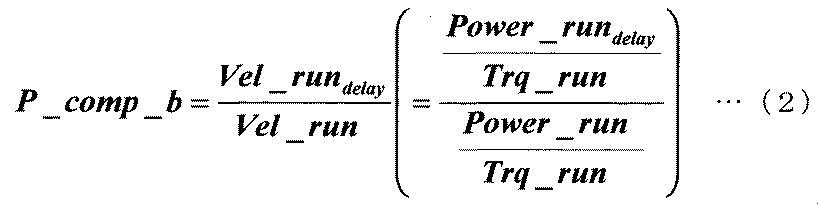
- the prior value (P_comp_b) of the engine output power suppression amount is determined by taking the ratio of the average speed before and after engine output power suppression. This calculation calculates how much power needs to be suppressed on average. In addition, for the sake of simplification of calculation, the calculation is performed assuming that the speed ratio can be handled as the power ratio.
- the relationship between power and traveling speed (wheel rotational speed) is “output power ⁇ traveling speed ⁇ drive wheel torque”.
- tire torque components are acceleration resistance and running resistance (rolling resistance component, gradient resistance component, air resistance component). From the above, the acceleration resistance changes as the running speed changes, but it is predicted that the change in running speed due to power suppression will be about 10% at most, so in this embodiment, the driving wheel torque before and after power suppression. Were calculated as if they were the same.
- the advance value (P_comp_b) of the engine output power suppression amount is multiplied by the maximum power output frequency (Pow_max_Rate) and the gradient value correction value (Grade).
- the slope value correction value is a value greater than or equal to 1 if the measured slope value [%] of the road surface is positive (uphill), and less than 1 if it is negative (downhill).
- the gradient value [%] when calculating the gradient correction value an average value of gradient values during one cycle or a value obtained by averaging gradient values [%] at the timing when the maximum power is output can be used.
- the latter method it is possible to calculate how much the engine output power needs to be reduced at the maximum output in consideration of the road surface gradient that contributes to the engine load.
- the reason for this calculation is that the driver frequently uses 0% (output power zero) and 100% (maximum output power) as the accelerator opening in the mine. In such a situation, it is preferable from the viewpoint of reducing fuel consumption to concentrate power suppression at the time of output of maximum power, rather than suppressing power over the entire travel time.
- the MUX 29 selects the limiters 25, 26, and 27 based on the output (selection signal (Jdg)) of the switching determination unit 28.
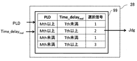
- the switching determination unit 28 the load (PLD) and the average (running) work waiting time (Time_delay real ) are input, and a selection signal (Jdg) is output using the map (control switching condition map) 99 shown in FIG. To do.
- the selection signal (Jdg) is determined by comparing the values of the load amount (PLD) and the average (running) work waiting time (Time_delay real ) with a preset threshold value.
- the threshold value (Mth) of the load capacity (PLD) in FIG. 9 is set to a value less than the maximum load capacity
- the threshold value (Tth) of the work waiting time (Time_delay real ) is the average value of the aforementioned work waiting time (Time_delay). It can be set to about half. Note that there may be a plurality of the two kinds of threshold values. When a plurality of threshold values are set, it is necessary to increase the number of limiters (two in the example of FIG. 4) that can be selected by the MUX 29 according to the number of threshold values when there is a work waiting time.
- the engine speed command calculation unit 13 is a block for determining an engine speed command (Ne *).
- the accelerator opening signal (Acl) input to the engine speed command calculation unit 13 is first input to the map 16.
- the map 16 defines the function of the accelerator opening signal (Acl).
- a temporary engine speed command value (Ne_b *) is output.
- the engine speed command value (Ne_b *) can be an engine speed command value when power is not suppressed.
- the map 16 is configured so that the maximum engine speed (Ne_max) specified by the engine is output with respect to the accelerator opening 100%, and the idling engine speed (Ne_min) is output with the accelerator opening 0%. Has been. Ne_b * output from the map 16 is input to each of the limiters 17, 18, and 19.
- the limiter 17 is selected when there is no work waiting time, the limiter 18 is selected when the work waiting time occurs during loading, and the limiter 19 is selected when the work waiting time occurs during idle loading.
- the limiters 17, 18, and 19 are selected by the MUX 22 and the switching determination unit 21.
- the switching determination unit 21 functions in the same manner as the switching determination unit 28 of FIG. 4 and outputs a selection signal (Jdg) based on the map 99 of FIG.
- the lower limit values of the limiters 17, 18, and 19 are all idle rotation speeds (Ne_min), the upper limit value of the limiter 17 is set as Ne_max, the upper limit value of the limiter 18 is set as Up_limit 3, and the upper limit value of the limiter 19 is set as Up_limit 4.
- the upper limit value needs to be calculated and set in the vehicle before traveling.
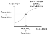
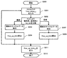
- the above-mentioned average engine output power upper limit (Pow_up_limit ave ) is input (S001). Thereafter, the average engine output power upper limit value (Pow_up_limit ave ) input in S001 is input to a predetermined function (map), and the average engine speed upper limit value (Ne_up_limit ave ) is determined (S002).
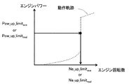
- a specific determination method for example, there is a method using a map of engine power and engine speed as shown in FIG.
- the average engine output upper limit value (Ne_up_limit ave ) can be calculated from the average engine output power upper limit value (Pow_up_limit ave ) using information of "maximum output value of engine output with respect to engine speed" indicated by a broken line in FIG. Also, as shown in FIG. 13, for example, when an operating point that actively uses the high efficiency region of the engine 1 and the generator is determined almost uniquely as indicated by a broken line, the average engine output is determined according to the broken line.
- the average engine speed upper limit (Ne_up_limit ave ) may be calculated from the power upper limit (Pow_up_limit ave ). Note that the operation locus in FIG.
- the upper limit of the engine speed may be determined using another locus.
- a map may be set so that The maps shown in FIGS. 12, 13, and 30 are merely examples, and other maps may be used as long as the functions (maps) uniquely determine the engine speed from the engine power.
- the calculation result of the loaded state is substituted into Up_limit3
- the calculation result of the empty state is substituted into Up_limit4.
- one or both of the threshold values (Mth, Tth) in FIG. 9 are set, and the number of limiters that can be selected by the MUX 22 when there is a work waiting time (FIG. 10). In this example, two) may be increased according to the number of the thresholds.
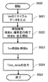
- the work waiting time calculation unit 15 calculates a work waiting time (Time_delay real ) using real-time traveling speed data (Vel) acquired during traveling.
- FIG. 14 shows a flow of calculation processing. First, time-series data of travel speed (Vel) and load (PLD) acquired during travel is input (S021). Thereafter, the traveling speed data is divided into data at the time of loading and emptying using the load amount data (PLD) (S022), and the latest one cycle data is extracted (S031). Next, a work waiting time (Time_delay (Tn)) is calculated in S023 and S024.
- the calculation method of the work waiting time is the same as that described in FIG. After calculating the work waiting time for one cycle, if there is a work waiting time calculated in the past before this calculation, calculate the average value with the data of the latest m work waiting times calculated in the past, An average (running) work waiting time (Time_delay real ) at the present time is calculated (S025). At this time, the number m to be averaged is set in advance. As described above, by calculating the actual (average) work waiting time for each cycle, it is possible to calculate the work waiting time accurately reflecting the situation at the site.
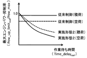
- FIG. 15 shows the result of comparing the relationship between the work waiting time and the suppression rate of the maximum engine output power in the present embodiment with the conventional one.
- the vertical axis represents the maximum engine power suppression rate (Pow_up_limit real / Pow_max), and the horizontal axis represents the work waiting time (Time_delay real ).
- the control device described above it is possible to suppress the engine power in consideration of the loading amount and the work waiting time with the work waiting time threshold (Tth) as a changing point.
- the engine power is suppressed only when the work waiting time exceeds the threshold (Tth), and the amount of suppression at that time is changed according to the presence or absence of the load. Since the waiting time is also taken into consideration, it can be set to a larger value than in the past (it is set to a smaller value than in the conventional case in terms of the suppression rate in FIG. 15). Further, in FIG. 15, the power suppression control of the present embodiment is set so that the engine power suppression amount increases stepwise as the work waiting time increases, and the comparison is made with the same work waiting time. In other words, it can be said that the engine power suppression amount is increased when the loading amount is small.
- the maximum engine power suppression rate of the control according to the first embodiment is 1 when the waiting time is zero, but is not necessarily 1.
- the maximum engine power suppression rate may be less than 1.
- the ECU 7 executes the control (power suppression control) for increasing the engine power suppression amount, assuming that the work waiting time has occurred.
- load presence / absence (loading amount) which is an index indicating the engine load during traveling and “travel route to the destination”
- the amount of engine power suppression during power suppression control was determined.
- the dump truck of the present embodiment configured as described above, when it is assumed that the work waiting time occurs, the engine power is suppressed so that the traveling time becomes longer with the average value of the work waiting time as a guide. Therefore, the fuel consumption can be reduced without prolonging the work cycle by actively delaying the arrival at the destination within the work waiting time. As a result, it is possible to improve the transportation efficiency and reduce the fuel consumption. It becomes.
- FIG. 16 shows a case where the past work waiting time coincides with the work waiting time currently running. Also, only 100% and 0% are used for the accelerator opening.
- the engine power suppression amount is determined according to the presence or absence of the load. Control that selectively changes the size is adopted, but when applied to a transportation vehicle that is used in an environment where the load capacity changes appropriately, the engine power suppression amount is continuously reduced as the load capacity decreases (The power suppression control may be executed so as to increase linearly / curvely. In this case, for example, when the load amount is 50% of the full load, the maximum engine power suppression rate is defined by a horizontal straight line located between the load and the empty load in the first embodiment in FIG.
- the power suppression control is executed only when the work waiting time exceeds the threshold (Tth).
- the engine power suppression amount increases as the work waiting time becomes longer by setting a plurality of work waiting time thresholds.
- the power suppression control may be executed so as to increase stepwise (discretely).
- the power suppression control may be executed so that the engine power suppression amount increases monotonously as the work waiting time increases.
- the average traveling speed after power suppression is calculated based on the average value (that is, the predicted value) of the work waiting time in the formula (1), but any work within the range of the actual work waiting time is calculated.
- the traveling speed after power suppression may be calculated for each work cycle based on the waiting time (for example, the work waiting time of the latest similar cycle), and the power suppression amount may be determined for each work cycle from the traveling speed.
- the configuration in which the power suppression control is performed on the whole way to the destination when it is determined that the work waiting time occurs but the engine output from various information including the road gradient, the road surface condition, etc.
- a configuration in which power suppression is concentrated in that section or in the vicinity thereof may be adopted. That is, it is good also as a structure which implements power suppression control in a part of the way to the destination.
- FIG. 18 shows the configuration of the ECU 7 according to this embodiment.
- the difference between the present embodiment and the first embodiment is that the upper limit value of the limiter is pre-calculated in the first embodiment, but the ECU 7 of the present embodiment has data related to the work cycle of the same type (load / empty load) as in the control.
- the upper limit value of the limiter Up_limit 5, Up_limit 6 described later
- PLD load amount
- Vel traveling speed
- Time_delay real average (during traveling) work waiting time
- accelerator opening Acl
- the functional blocks of the ECU 7 according to the present embodiment can be divided into three as in the first embodiment, and the work waiting time calculating unit 32 has the same function as the work waiting time calculating unit 15 in the first embodiment.
- the engine speed command calculation unit 30 and the engine output power command calculation unit 31 will be described.
- the engine output power command calculator 31 receives as inputs the accelerator opening (Acl), the load (PLD), and the average (running) work waiting time (Time_delay real ), and the engine output power command (Pow *) and the engine Output power output upper limit (Pow_up_limit real ) is output.
- the engine speed command calculation unit 30 receives the accelerator opening (Acl) and the engine output power upper limit (Pow_up_limit real ) as inputs, and outputs an engine speed command (Ne *).
- the engine output power command calculation unit 31 will be described with reference to FIG.
- the map 41 of the engine output power command calculation unit 31 outputs a temporary engine output power command value (Pow_b *) based on the input accelerator opening (Acl).
- an engine output power command value (Pow_b *) when power is not suppressed is calculated.
- the calculated Pow_b * is input to the limiter 42 and used as Up_limit 5 (described later) when the work waiting time (Time_delay real ) of the same type of work cycle as that of the current (control time) is zero (when power is not suppressed).
- the lower limit value of the limiter 42 is 0, and the upper limit value is Up_limit5.
- Up_limit 5 is determined by the engine output power upper limit calculation unit 40 or the map 41.
- the engine output power upper limit calculation unit 40 uses the load (PLD), travel speed (Vel), average (during travel) work waiting time (Time_delay real ), and accelerator opening (Acl) as inputs. (Pow_up_limt) is calculated.
- FIG. 20 shows a detailed calculation flow executed by the engine output power upper limit calculation unit 40.
- the process in the loaded state will be described, and the description of the process in the unloaded state will be omitted.
- the engine output power upper limit value calculation unit 40 inputs a loading amount (PLD), a traveling speed (Vel), an average (during traveling) work waiting time (Time_delay real ), and an accelerator opening (Acl) (S201).
- the travel speed (Vel) and accelerator opening (Acl) data is divided into a loaded state and an unloaded state based on the load amount (PLD) information (S202).
- the data for the most recent cycle in the loaded state (hereinafter sometimes referred to as “1 cycle data”) is extracted from the data divided in S202 (S203), and the engine output power upper limit (Pow_up_limt) for the 1 cycle data is calculated.
- PLD loading amount
- Vel traveling speed
- Time_delay real time
- Acl accelerator opening
- the calculation method of the engine output power upper limit (Pow_up_limt) for one cycle data in S204 is substantially the same as that described in the first embodiment with reference to FIG. 5 and equations (1) to (4), and the description thereof is omitted. To do.
- the engine output power upper limit value (Pow_up_limit real ) calculated in S204 is output to the limiter 42, the PCU 8, and the display device 10 (S211).
- the engine output power upper limit value (Pow_up_limit real ) output to the limiter 42 is substituted into Up_limit 5 when a work waiting time (Time_delay real ) occurs.
- the map 46 outputs a temporary output engine speed command value (Ne_b *) based on the accelerator opening (Acl) input to the engine speed command calculation unit 30.
- This command value (Ne_b *) is an engine speed command value when power is not suppressed.
- the calculated Ne_b * is input to the limiter 47, and is used as Up_limit 6 (described later) when the work waiting time of the same type of work cycle as the current (during control) is (Time_delay real ) is zero (when power is not suppressed).
- the lower limit value of the limiter 47 is an idle speed (Ne_min) defined by the engine 1, and the upper limit value is Up_limit6. Up_limit 6 is determined by the engine speed upper limit calculation unit 45 or the map 46.
- the engine speed upper limit calculation unit 45 receives the engine output power upper limit value (Pow_up_limit real ) as input and calculates the engine speed upper limit value (Ne_up_limit real ).
- the detailed calculation flow of the engine speed upper limit (Ne_up_limit real ) corresponds to the subscript “ave” in FIG. 11 described in the first embodiment changed to “real”, and thus the description is omitted.
- the maps of FIGS. 12, 13, and 30 used in the calculation flow of FIG. 11 can also be used in this embodiment, but the description thereof is omitted as in FIG.
- FIG. 22 shows the result of comparing the relationship between the work waiting time and the amount of suppression of engine output power in the present embodiment with the conventional one.
- the present embodiment by taking the logic configuration described above, it is possible to suppress the engine output power so as to increase monotonously as the work waiting time increases as compared to the case of the first embodiment shown in FIG. It becomes possible.
- the maximum engine power suppression rate of the control according to the present embodiment is 1 when the waiting time is zero, but it is not always necessary to be 1.
- the maximum engine power suppression rate may be less than 1 when the work waiting time is zero.
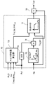
- FIG. 23 is a system block diagram according to the dump truck of the present embodiment.
- the dump truck according to the present embodiment performs communication between vehicles (between two dump trucks or between a dump truck and a work machine) and communication with a control tower that manages vehicle operation.
- the wireless communication device 80 is provided.
- the difference between the third embodiment and the first embodiment lies in the configuration of the travel data acquisition device 9 shown in FIG. 2 and the calculation method of work waiting time (Time_delay real ), and the other points are the same as those in the first embodiment.
- the travel data acquisition device 9 is arranged at other dump trucks traveling on the same route or at the destination (loading / unloading ground) of the own vehicle in addition to the data of various sensors acquired through the in-vehicle CAN of the first embodiment.
- the data of a working machine for example, a hydraulic excavator for loading, a wheel loader for transporting earth and sand after release, etc., which will be described as an example here
- a working machine for example, a hydraulic excavator for loading, a wheel loader for transporting earth and sand after release, etc., which will be described as an example here
- the travel data acquisition device 9 acquires an accelerator opening (Acl), a load amount (PLD), travel speed data (Vel), and the like of the host vehicle via the in-vehicle CAN and various sensors 91-96.
- the accelerator opening (Acl), load capacity (PLD), and travel speed data (Vel) of another vehicle are acquired via the wireless communication device 80, and the excavator notifies the end of loading, for example.
- the information of the time interval ( ⁇ Thorn) at which the horn (the signal that calls the dump truck for the next loading) sounds is acquired.
- a calculation flow of a work waiting time (Time_delay real ) when information is obtained from another vehicle via the wireless communication device 80 and various sensors 91-96 will be described with reference to FIG. Since data of other vehicles having the same route, vehicle grade, and vehicle performance is also acquired through the wireless communication device 80 and the processing of S505 and 510 is basically the same as FIG. 14, description thereof may be omitted. .
- data received from other vehicles or the like via the wireless communication device 80 is input one by one to update information on the traveling vehicle.
- the work waiting time calculation unit 15 is configured to execute a series of processes again from S020 when data from the own vehicle or another vehicle can be input.
- the travel speed (Vel) is calculated from the past data acquired via the travel data acquisition device 9 for the other vehicle (one or more) having the same route, vehicle rating and vehicle performance as the host vehicle and the host vehicle.
- Input time series data of loading capacity (PLD) PLD
- the process is. Based on the load (PLD), the traveling speed (Vel) of the host vehicle and other vehicles is divided into a loaded state and an empty state.
- S505 and 510 first, it is determined whether or not the host vehicle is traveling toward the destination by checking whether or not the traveling speed (Vel) of the host vehicle is equal to or higher than a predetermined threshold value. If it is not determined that the host vehicle is traveling, the process proceeds to S025 or S028, and the same process as in FIG. 14 is performed. On the other hand, if it is determined that the vehicle is traveling, the following processing is performed in S505 and 510. First, the latest travel time (Time_run) of the current travel route (see FIG. 8) is obtained from past data (data acquired via the travel data acquisition device 9) including other vehicles having the same route, vehicle grade, and vehicle performance. calculate. The travel time (Time_run) is calculated according to the procedure described above.
- This travel time (Time_run) is treated as a travel time (scheduled travel time) scheduled in the current work cycle of the vehicle.
- the elapsed time from the latest work end time (for example, points O, B, and D in FIG. 6) of the host vehicle is calculated as the actual travel time (Time_run_now). For example, when the current time is at point B ′ in the empty cycle of FIG. 6, the actual travel time (Time_run_now) from point B is “B′ ⁇ B”.
- the work waiting time is corrected by calculating Tn / ⁇ using this ⁇ and the work waiting time (Tn) calculated in S024.
- the work waiting time (Time_delay real ) calculated in the flow of FIG. 34 is output to the switching determination units 28 and 21, and is used to output a selection signal.
- the setting of the engine power suppression amount is also similar to the calculation of the work waiting time described above for the own vehicle and other vehicles (having the same route, vehicle rating, and vehicle performance as the own vehicle). It is assumed that time-series data of travel speed, accelerator opening, and load capacity are input, and calculation is appropriately performed according to the flowchart of FIG. However, the engine power suppression amount may be set based only on the own vehicle data as in the first embodiment. The same applies to the engine speed command (Ne *) calculated by the engine speed command calculation unit 13.
- the work waiting time is corrected as in the present embodiment, for example, when data is updated to a work waiting time longer than the target work waiting time during traveling of the host vehicle, the remaining traveling time is The shorter ( ⁇ is smaller), the more easily the power suppression control is executed, and the number of scenes where the engine power suppression amount can be quickly increased from the time of data update based on the latest work waiting time increases.
- the work waiting time cannot be updated unless the vehicle travels for one cycle.
- the work waiting time can be updated even during traveling. Therefore, the engine output power can be controlled more finely than in the first embodiment, so that the conveyance efficiency and the fuel consumption reduction effect can be enhanced.
- the number of work waiting time thresholds (Tth) may be increased.
- the number of scenes where the power suppression control functions increases.
- the actual running time (Time_run_now) may be calculated instead of the points O, B, and D if the time is included before the end time and before the end time.
- the travel start time Z see FIG. 6
- the actual travel time (Time_run_now) may be calculated based on that time. Note that these items also apply to the calculation of the travel time (Time_run) including other embodiments.
- the work waiting time (Time_delay real ) of the loading operation is estimated from the change in the traveling speed and the loading amount as described with reference to FIG.
- it gets information from the excavator (loading machine)
- it waits for the loading work by obtaining the time interval ⁇ Thorn that tells the end of loading (calling the dump truck that performs the next loading)
- Time (Time_delay real ) can be calculated.
- the work waiting time (Time_delay real ) can be calculated from ⁇ Thorn acquired in real time.
- the work waiting time can be calculated based on the time interval.
- the work waiting time can be updated more quickly than in the second embodiment, and the engine output power can be controlled more finely, so that the conveyance efficiency and the fuel consumption reduction effect can be enhanced.
- Embodiment 5 In which the technical idea of Embodiment 1 is applied to a dump truck including a mechanical power transmission device 2 is referred to as Embodiment 5.
- the basic configuration of this embodiment is the same as that of the first embodiment shown in FIG. 2, but the internal configurations of the power transmission device 2, the ECU 7 and the PCU 8 are different from those of the first embodiment.
- the power transmission device 2 will be described.
- the case where the power transmission device 2 is configured by a transmission using a gear or a torque converter is considered.
- the transmission switches gears (first speed, second speed, etc.) according to the running state.
- This switching is performed by the PCU 8.
- the PCU 8 performs control using the engine speed, accelerator opening, and wheel speed obtained from the ECU 7 as inputs.
- Such a configuration is sometimes called a mechanical type in this paper.
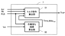
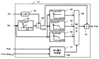
- the functional blocks can be divided into a torque command calculation unit 51 and a work waiting time calculation unit 52.
- the work waiting time calculation unit 52 has the same function as the work waiting time calculation unit 15 described in the first embodiment.
- the torque command calculator 51 outputs the torque command (Trq *) with the accelerator opening (Acl), engine speed (Ne), load capacity (PLD), average (running) work waiting time (Time_delay real ) as inputs. To do. Details of the torque command calculation unit 51 will be described with reference to FIG.
- the input engine speed (Ne) is converted into a torque command (Trq_max *) for the engine speed by the map 53.
- Trq_max * commands the maximum torque that can be used in the drive wheels 3L and 3R.
- Trq_b * the torque command value
- the filter 54 is used when power is not suppressed, the filter 55 is used when power is suppressed in a loaded state, and the filter 56 is used when power is suppressed in an empty state.
- Filter selection is performed by the MUX 58 based on a selection signal (Jdg) from the switching determination unit 57.
- the switching determination unit 57 has the same function as the switching determination unit 28 described in the first embodiment. As in the first embodiment, there may be a plurality of threshold values set by the switching determination unit 57. When setting multiple thresholds, it is necessary to increase the number of limiters that can be selected by MUX.
- the torque suppression amounts Up_limit7 and Up_limit8 change according to the engine speed.
- the average engine output power upper limit value (Pow_up_limit ave ) calculated in the same manner as in the first embodiment is used.
- the torque suppression amount needs to be changed according to the engine speed.
- the torque suppression amount (Trq_up_limit) needs to be determined before traveling. In addition, even when the traveling route is changed, it is necessary to perform the pre-calculation again using the new route data.
- time-series data of a traveling speed (Vel_o), an accelerator opening (Acl_o), and a loading amount (PLD_o) when the vehicle has traveled on the same route in the past is input (S301).
- the traveling speed data (Vel_o) and the accelerator opening (Acl_o) are divided into a loaded state and an unloaded state (S302).
- the flow in the loaded state will be mainly described.
- an engine output power upper limit (Pow_up_limit) is calculated in S304. Since the calculation method is the same as that of the first embodiment, the description is omitted.
- a torque suppression amount (Trq_up_limit) is calculated in S305.
- the torque suppression amount calculation method in S305 will be described with reference to FIG.
- the maximum engine output power (Pow_max_Ne) determined by the engine speed is indicated by a solid line, while the engine output power upper limit (Pow_up_limit) is indicated by a broken line.
- Pow_max_Ne is smaller than Pow_up_limit (I)
- Pow_max_Ne is larger than Pow_up_limit (II)
- Trq_up_limit 1 is set.
- Trq_up_limit a value obtained by dividing Pow_up_limit by Pow_max_Ne is set as Trq_up_limit.
- FIG. 28 shows the configuration of the ECU 7 of the present embodiment.
- the upper limit value of the limiter that requires pre-calculation in the fifth embodiment can be calculated from real-time data acquired during traveling.
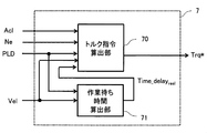
- the functional block of the ECU 7 can be divided into a torque command calculating unit 70 and a work waiting time calculating unit 71.
- the work waiting time calculating unit 71 is the work waiting time calculating unit described in the first embodiment. 15 has the same function.
- the torque command calculation unit 70 outputs the torque command (Trq *) with the accelerator opening (Acl), the engine speed (Ne), the load (PLD), and the travel speed (Vel) as inputs.
- FIG. 29 shows a configuration diagram of the torque command calculation unit 70.
- the input engine speed (Ne) is converted into a torque command (Trq_max *) for the engine speed by the map 75.
- Trq_max * commands the maximum torque that can be used in the drive wheels 3L and 3R.
- the accelerator opening (Acl) is divided by 100 by the divider 74, and the value is multiplied by Trq_max * by the multiplier 76, thereby calculating the torque command value (Trq_b *) when the power is not suppressed.
- the calculated Trq_b * is input to the filter 77.
- the filter 77 has the same characteristics as the filter described in the fifth embodiment.
- the torque suppression amount (Up_limit 9) used in the filter 77 is calculated by the torque suppression amount calculation unit 73.
- the torque suppression amount calculation unit 73 receives the load amount (PLD), travel speed (Vel), average (during travel) work waiting time (Time_delay real ), and accelerator opening (Acl). Details of the calculation method of the torque suppression amount are shown in FIG.
- the travel speed data (Vel) and the accelerator opening (Acl) are input for each cycle travel (S401), and the data is divided into a loaded state and an unloaded state based on the information of the loading amount (PLD) (S402). Hereinafter, the flow in the loaded state will be described.
- S403 After extracting the latest cycle data, the output power upper limit (Pow_up_limit) is calculated in S404. Thereafter, a torque suppression amount (Trq_up_limit) is calculated in S405.
- the details of the calculation method of the output power upper limit value (Pow_up_limit) and the torque suppression amount (Trq_up_limit) for one cycle data have already been described in the first and fifth embodiments, and will be omitted.
- the calculated torque suppression amount (Trq_up_limit real ) is input to the filter 77 and substituted for Up_limit9.
- the torque suppression amount (Trq_up_limit real ) is reset, and the torque suppression amount (Trq_up_limit real ) is recalculated with new route data.
- the calculation result Trq_up_limit real is input to the filter 77 and used as a set value of the torque suppression amount (Up_limit 9).
- Embodiment 7 is the one in which the technical idea of Embodiment 3 (FIG. 23) is applied to a dump truck provided with a mechanical power transmission device 2.
- the basic configuration of the seventh embodiment is the same as that shown in FIG.
- the seventh embodiment has the same basic configuration as that of the fifth embodiment, but there is a difference in the configuration of the travel data acquisition device 9 and the calculation method of the work waiting time (Time_delay real ).
- the travel data acquisition device 9 of the present embodiment also acquires data from the wireless communication device 80 that performs communication between vehicles and communication with a control tower that manages vehicle operation.
- the wireless communication device 80 and the calculation method of the work waiting time (Time_delay real ) have been described in the third embodiment.
- the update interval of the work waiting time is faster than in the fifth embodiment, and the engine output power can be controlled more finely, so that the conveyance efficiency and the fuel consumption reduction effect can be enhanced.
- Embodiment 8 applies the technical idea of Embodiment 4 to a dump truck provided with a mechanical power transmission device 2.
- the basic configuration of the eighth embodiment is the same as that of the sixth embodiment, there is a difference in the configuration of the travel data acquisition device 9 and the method of calculating the work waiting time (Time_delay real ).
- the travel data acquisition device 9 of the present embodiment also acquires data from the wireless communication device 80 that performs communication between vehicles and communication with a control tower that manages vehicle operation.
- the wireless communication device 80 and the calculation method of the work waiting time (Time_delay real ) have been described in the third embodiment.
- the update interval of the work waiting time is faster than that in the sixth embodiment, and the engine output power can be controlled more finely, so that the conveyance efficiency and the fuel consumption reduction effect can be enhanced.
- the present invention can also be applied to a case where the work waiting time is shortened. Further, the present invention is applicable not only when the dump truck travels unmanned but also when traveling unmanned.
- each of the above embodiments is not limited to a dump truck, but can be applied to a transport vehicle (for example, a large truck) or a self-propelled machine that generates a waiting time for loading / unloading work.
- a transport vehicle for example, a large truck
- a self-propelled machine that generates a waiting time for loading / unloading work.
- the two works of loading work (loading work) and earthing work (unloading work) at the loading site and the earthing site have been described as a set.
- the engine power may be suppressed based on the waiting time and the engine load.
- the load amount and the gradient are given as examples of the “index indicating the engine load during traveling”, but the air resistance and road surface resistance of the dump truck may be included in these.
- the present invention is not limited to the above-described embodiments, and includes various modifications within the scope not departing from the gist thereof.
- the present invention is not limited to the one having all the configurations described in the above embodiment, and includes a configuration in which a part of the configuration is deleted.
- a part of a configuration according to an embodiment can be added to or replaced with a configuration according to another embodiment.
- each configuration relating to the above-described control device for example, ECU 7, PCU 8
- functions and execution processes of the respective configurations, etc. are partly or entirely designed by hardware (for example, logic for executing each function is an integrated circuit) Or the like).
- the configuration related to the control device may be a program (software) that realizes each function related to the configuration of the control device by being read and executed by an arithmetic processing device (for example, a CPU).
- Information related to the program can be stored in, for example, a semiconductor memory (flash memory, SSD, etc.), a magnetic storage device (hard disk drive, etc.), a recording medium (magnetic disk, optical disc, etc.), and the like.
- control line and the information line are shown to be understood as necessary for the description of the embodiment.
- all the control lines and information lines related to the product are not necessarily illustrated. Not necessarily. In practice, it can be considered that almost all the components are connected to each other.
Landscapes
- Engineering & Computer Science (AREA)
- Chemical & Material Sciences (AREA)
- Combustion & Propulsion (AREA)
- Mechanical Engineering (AREA)
- General Engineering & Computer Science (AREA)
- Control Of Vehicle Engines Or Engines For Specific Uses (AREA)
Abstract
エンジン(1)と、エンジン(1)を制御するECU(7)とを備え、目的地の到着後に所定の作業を行うダンプトラックにおいて、ダンプトラックの目的地の到着後から作業の開始までの予測時間である作業待ち時間が長く、かつ、ダンプトラックのエンジン負荷が小さいほど、ダンプトラックの目的地への経路上でエンジンパワーの抑制量を大きくするようにECU(7)を構成する。
Description
本発明は、ダンプトラックを含む運搬車両に係り、特に運搬車両のエンジン制御に関するものである。
鉱山では、鉱石や剥土等の積荷を積込場から放土場まで運搬するために、積載量が100トン以上のダンプトラック(鉱山ダンプ)が多数稼動している。積込場から放土場の経路は一定に決められており、ダンプトラックは同じ経路を繰り返し往復走行する。1つの経路には複数台のダンプ(例えば全て同じ車格のダンプ)が走行しており、稼働時間は24時間である。このように、大型で長時間かつ複数台稼動するダンプトラックでは、単位コスト(イニシャルコスト+ランニングコスト)当りの仕事量(エネルギー量)で示される搬送効率が重要視されている。近年、この数値の向上を目指して、ランニングコスト低減が注目されている。その中で、エンジンで使用する燃料消費量の低減手法が提案されている。
国際公開第2006/043619号パンフレット(特許文献1)には、作業車両(ダンプトラック)の燃料消費量低減のためにエンジンが出力できるパワーを作業車両の負荷に応じて制限する方式が開示されている。本文献によると、まずドライバはエンジンの出力モードとしてパワーモード又は標準モードをモード設定スイッチにより選択する。選択された出力モードによりエンジン特性が決まり、標準モードはパワーモードに比べエンジンの使用領域が制限され、低出力で動作する。さらに、出力モード選択後、積載物の重量(積載量)やサスペンション圧力からの作業車両の負荷状態の高低を判断し、高負荷と判断された場合にはエンジンの使用領域を高出力側に広げ、低負荷と判断された場合にはエンジンの使用領域を低出力側に狭める処理を行う。したがって、低負荷と判断された場合には、エンジン出力パワーが抑制されることで余分なパワーが制限され、燃料消費量が低減される。
しかしながら、上記文献の技術では、作業車両の負荷のみに応じてエンジンの出力を変更するため、次のような問題が発生し得る。例えば、いずれかの出力モードで低負荷状態と判断されエンジン出力が抑制されると、燃料消費量が低下する一方で、走行速度までもが低下する可能性がある。走行速度の低下は作業車両の仕事量の低下につながるため、搬送効率が向上しないもしくは悪化する可能性がある。すなわち、上記文献の技術では、燃料消費量の低減と搬送効率の向上という2点を必ずしも両立できないという課題がある。
本発明は、上記のような従来技術の課題を検討し、その課題を解決するためになされたものである。従って、本発明の目的とすることころは、搬送効率の向上と燃料消費量の低減を両立できる運搬車両を提供する事にある。 本発明の前記ならびにその他の目的と新規な特徴は、本明細書の記述および添付図面から明らかになるであろう。
本願において開示される発明のうちの代表的なものについて簡単に説明すれば、下記のとおりである。
すなわち、エンジンと、前記エンジンを制御する制御装置とを備え、目的地の到着後に所定の作業を行う運搬車両において、前記制御装置は、前記運搬車両の前記目的地の到着後から前記作業の開始までの予測時間である作業待ち時間が長く、かつ、前記運搬車両のエンジン負荷が小さいほど、前記運搬車両の前記目的地への経路上でエンジンパワーの抑制量を大きくするように構成されているものとする。
本願において開示される発明のうち代表的なものによって得られる効果を簡単に説明すれば、作業待ち時間とエンジン負荷を考慮することで、搬送効率の向上と燃料消費量の低減を両立できる運搬車両を提供できる。
本願において開示される発明の代表的な実施の形態について詳細に説明する。参照する図面の参照符号は、それが付された構成要素の概念に含まれるものを例示するに過ぎない。
以下の各実施形態においては、エンジン負荷(積載量)と車両が作業を停止する作業待ち時間を考慮して、エンジンの最大出力を抑制することで、搬送効率の向上と燃料消費量の低減を両立できるエンジン制御装置およびそれを備えた鉱山向けダンプトラックについて説明する。
「積載量」とは、ダンプトラックに載せられる積載物の総重量であり、荷積み・荷下ろし等に応じて適宜変動する。「作業待ち時間」とは、ダンプトラックの目的地到着後に行われる作業(積込作業/放土作業)を開始するまでの待機時間であり、目的地到着時から作業開始時までの時間に相当する。目的地間の移動時間は作業待ち時間には含まない。「目的地」とは、或る地点(点)だけなく或る領域(面)も含む概念とし、「目的地への到着」とは、当該或る地点にダンプトラック(運搬車両)が到着したことと、当該或る領域内にダンプトラック内が進入したことの双方を含む概念とする。また、「作業待ち時間の開始時刻」は作業の内容、場所、主体等の条件に応じて変化し得るため一義に定める必要はない。すなわち、目的地への到着時を基準にして作業待ち時間を厳密に測定する必要は必ずしもなく、目的地への到着以後から作業開始以前までの間で、待機時間発生を認識し得る任意のきっかけから開始するものとしても良い。作業待ち時間の終了時刻についても同様に、作業終了以後から目的地への走行開始以前までの間で適宜決定すれば良い。
実施形態1の説明をする前に、まず、作業待ち時間を考慮することで搬送効率の向上と燃料消費量低減が両立できるメカニズムを説明する。
鉱山のダンプトラックの目的地は主に積み込み場(荷積み場)と放土場(荷下ろし場)であり、ダンプトラックは積み込み場と放土場を交互に行き来する。ダンプトラックは、積み込み場で積込作業(荷積み作業)を行い、積込作業完了後は放土場に向かって走行し、放土場で放土作業(荷下ろし作業)を行う。そして、放土作業完了後は、再び積み込み場に戻ってくる作業サイクルを繰り返す。例えば、放土場における作業待ち時間とは、放土場で前車が放土中にも関わらず自車が放土場に到着した場合に、当該前車の放土が終了するまで自車が待機する時間と考えることができる。作業待ちが発生する理由は、自車の走行速度が前車に比べて速いことや、前車の作業終了時刻が想定より遅延していることなどが挙げられるが、理由の如何は発明の実施に影響を与えない。
作業待ち時間の発生中は、自車が目的地にいくら早く到着しても、作業待ち時間の分は1作業サイクルに要する時間を短縮できない。このような状況において、自車は、前車の作業待ち時間内の到着であれば、走行速度を低下させることで目的地への到着時刻を遅延させても問題ない。そればかりか、走行速度の低下は燃料消費量の低減につながる。さらに、作業待ち時間内での到着であれば作業サイクルの時間に変化は無いので、燃料消費量の低減により搬送効率も向上する。本実施の形態では、作業待ち時間の発生時にエンジン負荷を考慮しながらエンジンパワーを抑制することで、目的地への道中での走行速度低下を促して目的地への到着時間を作業待ち時間の範囲内で遅延させる。これにより、燃料消費量の低減と搬送効率の向上が両立する。以後、このような動作・作用を実現する運搬車両の構成の例を説明する。
<実施形態1>
本実施形態の説明で用いる鉱山向けダンプトラックの構成について図1の側面図を用いて説明する。本実施形態の鉱山向けダンプトラックは、車体の前方に搭載されたエンジン1と、車体の上側後方に搭載され車体後方を中心に上下方向に回転可能な荷台(ベッセル)5と、車体の上側前方に設置された運転席6を備えている。また、車体下方前側には左右一対の従動輪4L,4R、車体下方後側には左右一対の駆動輪3L,3Rが配置されている。従動輪4L,4R及び駆動輪3L,3Rの周辺にはそれぞれサスペンション84L,84R,83L,83Rが搭載されている。各サスペンション84L,84R,83L,83Rの圧力をセンサ(積載量センサ)93(図2参照)で検出することで積載量を検出できる。
本実施形態の説明で用いる鉱山向けダンプトラックの構成について図1の側面図を用いて説明する。本実施形態の鉱山向けダンプトラックは、車体の前方に搭載されたエンジン1と、車体の上側後方に搭載され車体後方を中心に上下方向に回転可能な荷台(ベッセル)5と、車体の上側前方に設置された運転席6を備えている。また、車体下方前側には左右一対の従動輪4L,4R、車体下方後側には左右一対の駆動輪3L,3Rが配置されている。従動輪4L,4R及び駆動輪3L,3Rの周辺にはそれぞれサスペンション84L,84R,83L,83Rが搭載されている。各サスペンション84L,84R,83L,83Rの圧力をセンサ(積載量センサ)93(図2参照)で検出することで積載量を検出できる。
次にエンジン1の動力を駆動輪3L,3Rに伝達する動力伝達装置2について説明する。好ましい動力伝達装置2としては、例えば、界磁巻き線型発電機、インバータ、及び走行用の誘導モータ(走行モータ)の組み合わせが挙げられる。以後、このような構成を電気式と呼ぶ。電気式における動力伝達装置2では、エンジン1の回転エネルギーを発電機により電気エネルギーに変換し、インバータおよび走行モータに供給する。そして走行用モータが駆動輪3L,3Rを駆動することでダンプトラックの走行が可能となる。
次に、図2を用いて前述したコンポーネントや制御装置の接続関係を説明する。図1に示したダンプトラックは、さらに、ECU(エンジン制御装置:Engine Control Unit)7と、PCU(パワー制御装置:Power Control Unit)8と、走行データ取得装置9と、表示装置10を備えており、これら各装置7-10はコンピュータから構成されている。まず、コンポーネント間の接続について説明する。エンジン1は機械的機構により動力伝達装置2と接続される。さらに動力伝達装置2は、機械的機構により駆動輪3L,3Rに接続される。
次に制御装置とコンポーネントとの接続関係について説明する。まず、ECU7は、走行データ取得装置9から得られるアクセル開度(Acl)(アクセル踏み込みが最大の時、アクセル開度は100%)、積載量(PLD)、走行速度データ(Vel)を入力とする。本実施形態における走行データ取得装置9は、車両に設置されている各種センサ(アクセル開度センサ91、車両の走行速度センサ92、積載量センサ93、車両位置取得のためのGPSセンサ94、車体角度センサ95、油圧ポンプ圧センサ96など)から車載CAN(Controller Area Network)を通じてデータ取得可能な装置である。なお、以下の説明で適宜参照されるアクセル開度、走行速度、積載量、車両位置、車体角度、ポンプ圧のデータは、これら各種センサ91-96の検出値に基づいて取得されているものとする。また、図2上では各種センサ91-96は便宜上各1つずつしか示していないが、複数存在するセンサも含まれることがある。さらに、アクセル開度、走行速度、積載量、車両位置、車体角度およびポンプ圧のデータが取得可能であれば、センサ91-96以外のセンサを搭載し、当該センサからデータ取得する構成を採用しても構わない。
入力値に基づいてECU7は、エンジン回転数指令(Ne*)およびエンジン出力パワー指令(Pow*)を演算する。その結果、エンジン1の調速機(ガバナ)にはNe*が入力され、動力伝達装置2の制御装置であるPCU8にはNe*とPow*が入力され、そして、ドライバに走行速度を低減するべきか否かの表示をすることができる表示装置10にはPow*が入力される。
ここで、表示装置10について説明する。図17に表示装置10の表示処理に関する制御装置(コンピュータ)の処理を示す。当該制御装置は表示装置10に搭載されているが、車両内外の他の制御装置に機能を代替させても良い。
まず、1作業サイクル分(積荷状態(放土作業)であれば積荷終了から放土開始まで。空荷状態(積荷作業)であれば放土終了から積荷開始まで)のエンジン出力パワー指令(Pow*)が表示装置10に入力されると(S050)、その中から1サイクル中の最大値MPowが選択される(S051)。最大値MPowは駆動輪3L,3Rに供給できる最大のエンジンパワー(Pow_max)に除算され、その値が閾値より大きいかが判定される(S052)。もし、閾値より小さい場合は最大出力を抑制中であるメッセージ(例えば「パワー抑制中」)を表示し(S054)、閾値より大きい場合には通常通りのエンジン出力パワーであることをメッセージ(例えば「パワー抑制無」)で表示する(S053)。
この表示により、例えば同じアクセルの踏み込み量で走行速度が低下しても、その走行速度低下の原因は制御装置(ECU7)によるパワー抑制制御(エンジンパワー抑制量を大きくする制御)であり車両異常ではないことを認識しながらドライバは走行を継続できる。さらに、この表示からドライバは作業待ち時間の有無を黙示的に読み取ることができるので、ドライバによる無駄な加速を抑制する効果も期待できる。また、図17では2分岐の例を示しているが、S052の閾値を段階的に複数設定して表示を細分化しても良い。
次に、動力伝達装置2の制御装置であるPCU8について説明する。PCU8は、発電機とインバータの接続点における電圧の測定値、車輪速度、エンジン出力パワー指令値、エンジン回転数の測定値および指令値を入力とすることで、界磁巻き線型発電機の励磁電流指令や走行モータのトルク指令を動力伝達装置2に対して出力し動力伝達装置2を制御する。
図3を用いてエンジン制御装置(ECU)7について説明する。ECU7は、エンジン回転数やエンジン出力パワーの指令値(Ne*,Pow*)を決めるブロックである。ECU7を構成する機能ブロックを説明する。機能ブロックは大きく、エンジン回転数指令算出部13、エンジン出力パワー指令算出部14、作業待ち時間算出部15に分かれる。エンジン回転数指令算出部13は、アクセル開度信号(Acl)と積載量(PLD)、平均(走行中)作業待ち時間(Time_delayreal)を入力として、エンジン回転数指令(Ne*)を算出する。エンジン出力パワー指令算出部14も同じくアクセル開度信号(Acl)と積載量(PLD)、平均(走行中)作業待ち時間(Time_delayreal)を入力とし、エンジン出力パワー指令(Pow*)を算出する。最後に作業待ち時間算出部15は、積載量(PLD)と走行速度データ(Vel)を入力として、平均(走行中)作業待ち時間(Time_delayreal)を算出する。ここからは、エンジン回転数指令算出部13、エンジン出力パワー指令算出部14、作業待ち時間算出部15の詳細について説明する。
はじめに、図4を用いて、エンジン出力パワー指令算出部14の詳細を説明する。エンジン出力パワー指令算出部14はエンジンの出力パワー指令(Pow*)を決定するブロックである。マップ24は、アクセル開度信号(Acl)が入力されると図中のグラフに従ってエンジン出力パワー指令値(Pow_b*)を出力する関数を規定している(以下において、「マップ」とは、或る値が入力されると所定の規則に従って他の或る値を出力する関数を示すものとする)。まず、エンジン出力パワー指令算出部14に入力されたアクセル開度信号(Acl)はマップ24に入力され、そのアクセル開度信号(Acl)から仮のエンジン出力パワー指令値(Pow_b*)が決定される。この指令値(Pow_b*)はパワー抑制しない場合のエンジン出力パワー指令値となる。マップ24は、エンジン出力パワー指令がアクセル開度100%で最大(Pow_max)で、アクセル開度0%では0(ゼロ)となるように構成されている。その後、Pow_b*はリミッタ25、26,27のそれぞれに入力される。
リミッタ25は作業待ち時間が無い場合に選択され、リミッタ26,27は作業待ち時間がある場合に選択される。さらに、リミッタ26は積荷走行時に、リミッタ27は空荷走行時に選択される。リミッタ25,26,27の下限値はいずれも0(ゼロ)であり、リミッタ25の上限値はPow_max、リミッタ26の上限値はUp_limit1、リミッタ27の上限値はUp_limit2として設定される。3者の大小関係は図4に図示したように「Up_limit2<Up_limit1<Pow_max」となる傾向が強いが、条件によっては他の大小関係も成立し得る。
ここで、上限値Up_limit1とUp_limit2の決定方法について述べる。本実施形態において、前記上限値(Up_limit1、Up_limit2)は走行前に事前に算出し車両に設定しておく必要がある。また、走行する経路が変更になった場合も、新たな経路のデータを用いて事前計算を再度やり直す必要もある。図5に事前計算のフローを示す。まず、本実施形態では過去にパワー抑制制御を行わない状態で同一経路を走行した際の走行速度データ(Vel_o)、アクセル開度(Acl_o)及び積載量(PLD_o)の時系列データを用意する(S101)。その後、積載量の情報(PLD_o)と後述の閾値(閾値Mth)を用いて、Vel_o、Acl_oを積荷の際のデータと空荷の際のデータに分割する(S102)。鉱山ダンプにおける積荷状態とは、おおむね満積載状態であることが実情であるため、Vel_o、Acl_oを積荷の際のデータと空荷の際のデータに分けるための閾値としては、例えば、満積載量の半分の値を用いることができる。
次に積荷データに関する処理(S103-S108)について述べる。データ分割後、さらにデータを1サイクル(積荷状態であれば積荷終了から放土開始までとし、空荷状態であれば放土終了から積荷開始までとする)ごとに分割する。これによりVel_o、Acl_oは1サイクル毎の時系列データとなる(S103)。そして、S103で分割したデータに基づいて、作業待ち時間(Time_delay)、走行時間(Time_run)、走行距離(Distance)、平均走行速度(Vel_run)、最大パワー出力頻度(Pow_max_Rate)をサイクルごとに計算する(S104)。次にそれぞれの定義について説明する。
まず、積荷状態における作業待ち時間(Time_delay)は、例えば、放土場において前車が放土作業中にも関わらず、自車が放土場に到着し前車の放土作業が終了するまで自車が待機する時間と考えることができる。このとき、作業待ち時間の計算は、積荷走行が終了した時刻(積荷走行終了時刻)から、放土を開始する時刻(放土開始時刻)までの差と定義できる。積荷走行終了時刻は、例えば、積載量が所定の閾値以上(例えば、満積載の半分以上で、後述の閾値Mth以上)で、走行速度がゼロより大きい条件が一定期間継続した後に速度がゼロになった場合の時刻として検出可能である。放土開始時刻は、例えば、積載量が前記閾値未満に達した時刻として検出可能である。また、放土開始時刻は、制御入力を追加する必要はあるが、荷台5を仰腑動させる油圧シリンダ(ホイストシリンダ)に圧油を供給する油圧ポンプの圧力が閾値を超えた時刻として検出しても良い。また、当該ホイストシリンダの圧力を検出するセンサを追加設置し、その検出圧が閾値を超えた時刻からも検出可能である。さらに、車体に対する荷台の傾斜角を検出し当該検出角度が閾値を超えた時刻からも検出可能である。
一方、空荷状態においての作業待ち時間(Time_delay)は、例えば、積み込み場において前車が積み込み作業中にも関わらず、自車が積み込み場に到着し前車の積み込み作業が終了するまで自車が待機する時間と考えることができる。このとき、作業待ち時間の計算は、空荷走行終了時刻から積み込み開始時刻までの差として定義できる。空荷走行終了時刻は、例えば、積載量が前記閾値未満で、走行速度がゼロより大きい条件が一定期間継続した後に速度がゼロになった場合の時刻として検出可能である。積み込み開始時刻は、例えば、積載量がゼロから前記閾値以上となった時刻として検出可能である。
それぞれの作業待ち時間(放土待ち時間及び積込待ち時間)を時系列データで表すと図6となる。作業待ち時間(Time_delay)の事前計算は、図7に示すフローで実施する。はじめに、積荷時の1サイクル分の走行速度データ(Vel)データを入力する(S021)。次に放土待ち時間を計算するため、積荷走行終了時刻をA、放土開始時刻をB(計算対象が積荷待ち時間の場合には、空荷走行終了時刻をC、積荷開始時刻をDとし、以下の説明でAをCに、BをDに読み替える)として走行速度データから抽出する(S022)。その後、時刻AとBの差分を取ること(S023)でサイクルデータ1個に対する作業待ち時間(Time_delay(但し図中ではTnと表記))が計算でき、これを出力する(S024)。
次に、図8に走行距離(Distance)、平均走行速度(Vel_run)、最大パワー出力頻度(Pow_max_Rate)の定義を示す。平均走行速度(Vel_run)は1サイクルの走行速度の平均値である。走行時間(Time_run)は、積荷走行では、積載量が所定の閾値以上かつ走行速度がゼロより大きい条件が継続した時間であり、空荷走行では、積載量が所定の閾値未満かつ走行速度がゼロより大きい条件が継続した時間である。走行距離(Distance)は平均走行速度(Vel_run)と走行時間(Time_run)の積である。最大パワー出力頻度(Pow_max_Rate)は1サイクル時間内でエンジン最大パワーを出力した時間の割合を示した値であり、当該時間はアクセル開度がフルアクセルになった期間から算出する。最大パワーの定義は、エンジンの最大出力値で良い。または、エンジンの最大出力から一定量減じた値でも良い。
図5のS104の値を計算終了後、下記式(1)を用いてパワー抑制後の平均走行速度(Vel_rundelay)を計算する(S105)。パワー抑制後の平均走行速度は、作業待ち時間(Time_delay)の分だけ走行時間を長くするため、パワー抑制前の平均走行速度に比べて低下する。
次に下記式(2)から(4)を用いて、パワー抑制後のエンジン出力パワーを決める(S106)。
まず式(2)では、エンジン出力パワー抑制前後の平均速度の比を取ることでエンジン出力パワーの抑制量の事前値(P_comp_b)を決める。この計算では、平均的にどの程度パワーを抑制する必要があるかを計算している。また、今回は計算の簡易化のため、速度比がパワー比として扱えるとして計算を行っている。パワーと走行速度(車輪の回転速度)との関係は、「出力パワー∝走行速度×駆動輪トルク」である。また、タイヤトルクの成分は、加速抵抗と走行抵抗(転がり抵抗成分、勾配抵抗成分、空気抵抗成分)となる。以上より、走行速度が変わると加速抵抗が変化するが、パワー抑制による走行速度の変化は大きくても十数%程度になると予測されるため、本実施形態においては、パワー抑制前後で駆動輪トルクは同一であるとみなして計算を行った。
次に式(3)では、エンジン出力パワーの抑制量の事前値(P_comp_b)を最大パワー出力頻度(Pow_max_Rate)と勾配値補正値(Grade)で乗算する。ここで勾配値補正値は、測定された路面の勾配値[%]が正(登り坂)であれば1以上の、負(下り坂)であれば1未満の値であり、勾配値が大きくなるほど値が大きくなるように計算を行う(勾配値補正値=勾配値[%]×α。αは定数)。勾配補正値を計算する際の勾配値[%]は、1サイクル中の勾配値の平均値や、最大パワーが出力されるタイミングの勾配値[%]を平均した値を用いることができる。後者の方法によれば、エンジン負荷の一因である路面勾配を考慮して最大出力時にどの程度エンジン出力パワーを低減する必要があるかを計算できる。この計算をする理由は、鉱山においてドライバはアクセル開度として主に0%(出力パワーゼロ)及び100%(出力パワー最大)を多用するためである。このような状況では、走行時間の全体に亘ってパワー抑制するのではなく、最大パワーの出力時にパワー抑制を集中させることが燃料消費量低減の観点から好ましい。
また、勾配が大きい場合には走行速度の低下が大きくなり、勾配値に基づいてパワー抑制量の補正を行う必要もあるため、式(3)の計算を行う。なお、勾配値[%]の測定値がない場合には、勾配補正値を常時1として計算を行ってもよい。この場合は、エンジン出力パワー上限値(エンジンパワー抑制量)の算出に考慮されるエンジン負荷は積載量のみとなり、勾配値は考慮されないことになる。
最後に式(4)で、駆動輪3L,3Rに供給できる最大パワー(Pow_max)をP_compと乗算すれば、エンジン出力パワー上限値(Pow_up_limit)が計算できる。前記した計算を全サイクル終了すると(S107)、全サイクル分の平均値を計算(S108)し、これを平均エンジン出力パワー上限値(Pow_up_limitave)として出力する(S115)。ここまで積荷時の計算法について述べたが、空荷時でも計算方法は同様であり、図5中のS109からS114までの処理の説明は省略する。なお、同一経路であれば、空荷時は最大パワー出力頻度計算(Pow_max_Rate)が積荷時よりも小さくなるため、パワー抑制量(P_comp)は積荷時に比べて大きくなる傾向がある。
ここで、平均エンジン出力パワー上限値(Pow_up_limitave)をリミッタ26、27に適応する場合、積荷状態の計算結果はUp_limit1(リミッタ26)に代入する。また、空荷状態の計算結果は、Up_limit2(リミッタ27)へ代入する。
次にこの3つのリミッタ25,26,27の選択方法について述べる。図4においてMUX29は切り替え判定部28の出力(選択信号(Jdg))に基づいて、リミッタ25,26,27の選択を行う。切り替え判定部28では、積載量(PLD)と平均(走行中)作業待ち時間(Time_delayreal)を入力として、図9に示すマップ(制御切り替え条件マップ)99を用いて選択信号(Jdg)を出力する。マップ99では、積載量(PLD)と平均(走行中)作業待ち時間(Time_delayreal)の値をあらかじめ設定した閾値と比較して、選択信号(Jdg)が決定される。図9中の「選択信号」の数字は、図4中でリミッタ25,26,27からMUX29に向かう3本の矢印に付された数字に対応しており、MUX29は「選択信号」の番号と同じ矢印が出ているリミッタ25,26,27からの出力を選択的に入力する。図9中の積載量(PLD)の閾値(Mth)は最大積載量未満の値で設定し、作業待ち時間(Time_delayreal)の閾値(Tth)は前記した作業待ち時間(Time_delay)の平均値の半分程度と設定することができる。なお、前記した2種の閾値はそれぞれ複数あっても良い。複数の閾値を設定する場合、作業待ち時間が有る場合にMUX29により選択され得るリミッタの数(図4の例では2つ)を閾値の数に応じて増加する必要がある。
次に、図10を用いてエンジン回転数指令算出部13の詳細を説明する。エンジン回転数指令算出部13はエンジン回転数指令(Ne*)を決定するブロックである。エンジン回転数指令算出部13に入力されたアクセル開度信号(Acl)はマップ16にまず入力される。
マップ16はアクセル開度信号(Acl)の関数を規定しており、アクセル開度信号(Acl)が入力されると仮のエンジン回転数指令値(Ne_b*)を出力する。エンジン回転数指令値(Ne_b*)はパワー抑制しない場合のエンジン回転数指令値となり得る。マップ16は、アクセル開度100%に対してエンジンが規定する最大回転数(Ne_max)が出力されるように、かつ、アクセル開度0%ではアイドル回転数(Ne_min)が出力されるように構成されている。マップ16から出力されたNe_b*はリミッタ17,18,19のそれぞれに入力される。
リミッタ17は作業待ち時間が無い場合に選択され、リミッタ18は積荷走行時に作業待ち時間が発生した場合に選択され、リミッタ19は空荷走行時に作業待ち時間が発生した場合に選択される。リミッタ17,18,19の選択はMUX22および切り替え判定部21で行う。切り替え判定部21は、図4の切り替え判定部28と同じように機能し図9のマップ99に基づいて選択信号(Jdg)を出力する。リミッタ17,18,19の下限値はいずれもアイドル回転数(Ne_min)であり、リミッタ17の上限値はNe_max、リミッタ18の上限値はUp_limit3、リミッタ19の上限値はUp_limit4として設定される。本実施形態において、前記上限値は走行前に算出し車両に設定しておく必要がある。
ここで、図11を用いて、上限値Up_limit3とUp_limit4の決定方法について述べる。はじめに、前記した平均エンジン出力パワー上限値(Pow_up_limitave)を入力する(S001)。その後、S001で入力した平均エンジン出力パワー上限値(Pow_up_limitave)を所定の関数(マップ)に入力し、平均エンジン回転数上限値(Ne_up_limitave)を決定する(S002)。具体的な決定方法は、例えば、図12に示すようなエンジンパワーとエンジン回転数のマップを利用する方法がある。図12中の破線で示す「エンジン回転数に対するエンジン出力の最大出力値」の情報を用いて、平均エンジン出力パワー上限値(Pow_up_limitave)から平均エンジン回転数上限値(Ne_up_limitave)を計算できる。また、図13に示すように、例えば、エンジン1と発電機の高効率領域を積極的に使用するような動作点を破線のようにほぼ一意的に決めている場合、当該破線に従って平均エンジン出力パワー上限値(Pow_up_limitave)から平均エンジン回転数上限値(Ne_up_limitave)を計算しても良い。なお、図13における動作軌跡は一例に過ぎず、この他の軌跡を用いてエンジン回転数上限を決定しても良い。さらに、エンジン回転数の動作範囲を変更したくない場合は、図32に示すようにどの平均エンジン出力パワー上限値(Pow_up_limitave)に対しても一定の平均エンジン回転数上限値(Ne_up_limitave)となるようにマップを設定しても良い。なお、図12,13,30に示したマップは一例に過ぎず、エンジンパワーからエンジン回転数が一意に定まる関数(マップ)であれば上記以外のものも利用可能である。
上記の計算結果をリミッタ18,19に適応する場合、積荷状態の計算結果はUp_limit3に代入し、空荷状態の計算結果はUp_limit4に代入する。なお、リミッタ25,26,27の場合と同様に、図9の閾値(Mth,Tth)の一方又は双方を複数設定し、作業待ち時間が有る場合にMUX22により選択され得るリミッタの数(図10の例では2つ)を当該閾値の数に応じて増加しても良い。
さらに、図14を用いて作業待ち時間算出部15の詳細を説明する。作業待ち時間算出部15では、走行中に取得したリアルタイムな走行速度データ(Vel)を用いて、作業待ち時間(Time_delayreal)を計算する。図14に計算処理のフローを示す。まず、走行中に取得した走行速度(Vel)と積載量(PLD)の時系列データを入力する(S021)。その後、積載量データ(PLD)を用いて積荷および空荷時のデータに走行速度データを分割後(S022)、最新の1サイクルのデータを抽出する(S031)。次にS023,S024で作業待ち時間(Time_delay(Tn))を計算する。作業待ち時間(Time_delay)の計算方法は図7において説明した内容と同一である。1サイクル分の作業待ち時間計算後、今回の計算より前に過去に計算した作業待ち時間がある場合には、過去に計算した直近m個の作業待ち時間のデータとの平均値を算出し、現時点での平均(走行中)作業待ち時間(Time_delayreal)を算出する(S025)。この時、平均する個数mは、あらかじめ設定しておく。このように1サイクルごとに実際の(平均)作業待ち時間の計算を実施することで、現場の状況を的確に反映した作業待ち時間が計算可能となる。
ここで、図15に本実施形態における作業待ち時間と最大エンジン出力パワーの抑制率との関係を、従来と比較した結果を示す。縦軸は、最大エンジンパワー抑制率(Pow_up_limitreal/Pow_max)であり、横軸は作業待ち時間(Time_delayreal)である。従来は、作業待ち時間とは関係は無く、積載量(積荷か空荷か)のみに応じてエンジンパワーの抑制を実施している。一方、本実施形態においては、前記した制御装置を用いることで、作業待ち時間の閾値(Tth)を変化点として、積載量と作業待ち時間を考慮したエンジンパワーの抑制が可能となる。具体的には、本実施の形態では、作業待ち時間が閾値(Tth)を越えた場合にはじめてエンジンパワーの抑制を実施しており、その際の抑制量は積荷の有無に応じて変えつつ作業待ち時間も考慮しているため従来よりも大きな値にできる(図15の抑制率でみれば従来よりも小さな値に設定されている)。また、図15において本実施形態のパワー抑制制御は、作業待ち時間の増加に応じて階段状にエンジンパワー抑制量が大きくなるように設定しており、かつ、同じ作業待ち時間で比較した場合に積載量が小さいときの方がエンジンパワー抑制量を大きくしていると換言できる。
なお、図15では実施形態1に係る制御の最大エンジンパワー抑制率が待ち時間がゼロの時に1となっているが、必ずしも1である必要はない。例えば、作業待ち時間に関係なく、積載量などのエンジン負荷に応じてエンジン出力を調整する機能が手動、自動に限らず車両に搭載されている場合、例えば空積載時には、大きな出力は必要としないので、図32に示すように、作業待ち時間がゼロの時でも、最大エンジンパワー抑制率が1未満となっても良い。
以上のように、本実施形態のダンプトラックでは、まず、同種(積荷作業/放土作業)の作業サイクルにおける作業待ち時間(Time_delayreal)が閾値(Tth)以上の場合に、現在の作業サイクルでも作業待ち時間が発生しているとみなし、エンジンパワー抑制量を大きくする制御(パワー抑制制御)をECU7により実行することとした。そして、そのパワー抑制制御中にどの程度エンジンパワーを抑制すべきかを決定するための指標として走行中のエンジン負荷を示す指標である「積荷の有無(積載量)」と「目的地までの移動経路の勾配値(勾配値補正値)の大小」を考慮しつつ、作業待ち時間(Time_delay)の平均値を目安にその分だけ走行時間が長くなるように、式(1)-(4)を利用してパワー抑制制御中のエンジンパワー抑制量を決めた。このように構成した本実施の形態のダンプトラックによれば、作業待ち時間が発生するとみなされた場合には、作業待ち時間の平均値を目安に走行時間が長くなるようにエンジンパワーが抑制されるので、作業待ち時間の範囲内で目的地への到着を積極的に遅延させることで作業サイクルを長くすることなく燃料消費量を低減でき、その結果として搬送効率向上と燃費低減の両立が可能となる。
次に図16を用いて本実施形態の効果を説明する。図16では、過去の作業待ち時間が現在走行中の作業待ち時間と一致している場合を示している。また、アクセル開度は100%と0%のみを用いることとする。
まず、積荷状態において、従来制御では積載量に応じたエンジン出力パワー制御しかしていないため、作業待ち時間に応じたエンジン出力パワー制御は行われず、結果的に作業待ち時間が発生している。一方で、本実施形態を用いると、作業待ち時間を考慮できるため、エンジン出力を従来より低減して走行できることが分かる。これは、空荷走行においても同様のことが言える。また、エンジン出力が抑制される分、燃費も低減できることから、本実施形態を用いることで、搬送効率の向上と燃費の低減の両立が可能となる。
なお、上記では、鉱山ダンプの積荷は満積載か空かの略2択であるという実情に鑑み、作業待ち時間が閾値(Tth)を越えた場合、積荷の有無に応じてエンジンパワー抑制量の大きさを選択的に変更する制御を採用したが、積載量が適宜変化する環境で使用される運搬車両に適用する場合等には、積載量の減少に合わせてエンジンパワー抑制量が連続的(直線的/曲線的)に大きくなるようにパワー抑制制御を実行しても良い。この場合、例えば、積載量が満積載の50%のときには、図15における実施形態1の積荷と空荷の中間に位置する水平の直線で最大エンジンパワー抑制率が規定されることになる。
また、上記では作業待ち時間が閾値(Tth)を超えた場合のみにパワー抑制制御を実行するように構成したが、作業待ち時間の閾値を複数設定し、作業待ち時間が長くなるほどエンジンパワー抑制量が階段状(離散的)に大きくなるようにパワー抑制制御を実行しても良い。さらに、閾値の利用に代えて、作業待ち時間の増加に応じてエンジンパワー抑制量が単調に増加するようにパワー抑制制御を実行しても良い。
また、上記では、式(1)において、パワー抑制後の平均走行速度を作業待ち時間の平均値(即ち予測値)に基づいて算出したが、実際の作業待ち時間の範囲内で、任意の作業待ち時間(例えば直近の同種のサイクルの作業待ち時間)に基づいてパワー抑制後の走行速度を作業サイクル毎に算出し、その走行速度からパワー抑制量を作業サイクル毎に定めても良い。
また、上記では、作業待ち時間が発生すると判断された場合に目的地への道中全般でパワー抑制制御を実施する構成を説明したが、走行路の勾配、路面状態等を含む各種情報からエンジン出力パワーが他の区間に比して大となる区間が予測可能又は判明している場合にはその区間やその近傍でパワー抑制を集中する構成を採用しても良い。すなわち、目的地への道中の一部でパワー抑制制御を実施する構成としても良い。
<実施形態2>
本実施形態において、実施形態1にて説明済みの事項に関しては説明を省略する(後の実施形態も同様とする)。例えば、作業待ち時間を考慮することで搬送効率の向上と燃料消費量低減が両立できる基本メカニズムは実施形態1と同様である。
本実施形態において、実施形態1にて説明済みの事項に関しては説明を省略する(後の実施形態も同様とする)。例えば、作業待ち時間を考慮することで搬送効率の向上と燃料消費量低減が両立できる基本メカニズムは実施形態1と同様である。
図18に本実施形態に係るECU7の構成を示す。本実施形態と実施形態1との違いは、実施形態1ではリミッタの上限値を事前計算したが、本実施形態のECU7では、制御時と同じ種類(積荷/空荷)の作業サイクルに係るデータ(例えば、積載量(PLD)、走行速度(Vel)、平均(走行中)作業待ち時間(Time_delayreal)、アクセル開度(Acl))に基づいてリミッタの上限値(後述のUp_limit5,Up_limit6)をリアルタイムに算出する点にある。
本実施形態に係るECU7の機能ブロックは実施形態1と同様に3つに分けることができ、作業待ち時間算出部32は実施形態1の作業待ち時間算出部15の機能と同一である。ここではエンジン回転数指令算出部30およびエンジン出力パワー指令算出部31について説明する。
エンジン出力パワー指令算出部31は入力に、アクセル開度(Acl)と積載量(PLD)、平均(走行中)作業待ち時間(Time_delayreal)を入力として、エンジン出力パワー指令(Pow*)とエンジン出力パワー上限値(Pow_up_limitreal)を出力する。また、エンジン回転数指令算出部30はアクセル開度(Acl)とエンジン出力パワー上限値(Pow_up_limitreal)を入力として、エンジン回転数指令(Ne*)を出力する。
図19を用いて、エンジン出力パワー指令算出部31について説明する。エンジン出力パワー指令算出部31のマップ41は、入力されたアクセル開度(Acl)に基づいて仮のエンジン出力パワー指令値(Pow_b*)を出力する。マップ41ではパワー抑制しない場合のエンジン出力パワー指令値(Pow_b*)を算出する。算出されたPow_b*はリミッタ42に入力され、現在(制御時)と同種の作業サイクルの作業待ち時間(Time_delayreal)がゼロの場合(パワー抑制しない場合)のUp_limit5(後述)として利用される。
リミッタ42の下限値は0であり、上限値はUp_limit5である。Up_limit5はエンジン出力パワー上限値算出部40又はマップ41により決定される。エンジン出力パワー上限値算出部40は入力として、積載量(PLD)、走行速度(Vel)、平均(走行中)作業待ち時間(Time_delayreal)、アクセル開度(Acl)を用いてエンジン出力パワー上限(Pow_up_limt)を算出する。
エンジン出力パワー上限値算出部40が実行する詳細な計算フローを図20に示す。なお、ここでは代表して積荷状態における処理を説明し、空荷状態の処理については説明を省略する。
はじめに、エンジン出力パワー上限値算出部40は、積載量(PLD)、走行速度(Vel)、平均(走行中)作業待ち時間(Time_delayreal)、及びアクセル開度(Acl)を入力し(S201)、積載量(PLD)の情報を元に積荷状態と空荷状態に走行速度(Vel)及びアクセル開度(Acl)のデータを分割する(S202)。その後、S202で分割したデータから積荷状態の直近の1サイクル分のデータ(以下「1サイクルデータ」と称することがある)を抽出し(S203)、1サイクルデータに対するエンジン出力パワー上限(Pow_up_limt)を計算する(S204)。S204の1サイクルデータに対するエンジン出力パワー上限(Pow_up_limt)の計算方法は、実施形態1で図5及び式(1)-(4)等を参照して説明したものと略同一であるため説明は省略する。S204で算出されたエンジン出力パワー上限値(Pow_up_limitreal)はリミッタ42、PCU8及び表示装置10に出力される(S211)。リミッタ42に出力されたエンジン出力パワー上限値(Pow_up_limitreal)は、作業待ち時間(Time_delayreal)が発生している場合にUp_limit5に代入される。
なお、走行経路が変更になった場合は、エンジン出力パワー上限値(Pow_up_limitreal)をリセットして再度図20の計算フローを実行することで、新たな経路データのエンジン出力パワー上限値(Pow_up_limitreal)を再計算する。
次に図21を用いてエンジン回転数指令算出部30の説明を行う。マップ46は、エンジン回転数指令算出部30に入力されたアクセル開度(Acl)に基づいて仮の出力エンジン回転数指令値(Ne_b*)を出力する。この指令値(Ne_b*)はパワー抑制しない場合のエンジン回転数指令値となる。算出されたNe_b*は、リミッタ47に入力され、現在(制御時)と同種の作業サイクルの作業待ち時間が(Time_delayreal)がゼロの場合(パワー抑制しない場合)のUp_limit6(後述)として利用される。リミッタ47の下限値はエンジン1が規定するアイドル回転数(Ne_min)であり、上限値はUp_limit6である。Up_limit6はエンジン回転数上限値算出部45又はマップ46により決定される。
エンジン回転数上限値算出部45はエンジン出力パワー上限値(Pow_up_limitreal)を入力としてエンジン回転数上限値(Ne_up_limitreal)を計算する。エンジン回転数上限値(Ne_up_limitreal)の詳細な計算フローは、実施形態1で説明した図11中の添字の「ave」を「real」に変更したものに対応するため説明は省略する。図11の計算フローで利用される図12,13,30のマップも本実施形態に利用可能であるが図11と同様に説明を省略する。
ここで、図22に本実施形態における作業待ち時間とエンジン出力パワーの抑制量の関係を従来と比較した結果を示す。本実施形態は、前記したロジック構成をとることで、図15に示した実施形態1の場合と比較して、作業待ち時間の増加に応じて単調増加するようにエンジン出力パワーを抑制することが可能となる。本実施形態を用いることで、エンジン出力パワー上限値などの事前計算が必要なくかつ、作業待ち時間のバラツキに対してもより細くエンジン出力パワーを制御することができるため、搬送効率と燃費低減効果を高めることができる。
なお、図22では本実施形態の制御の最大エンジンパワー抑制率が待ち時間がゼロの時に1となっているが、必ずしも1である必要はない。例えば、積載量などの作業負荷に応じてエンジン出力を調整する機能が手動、自動に限らず車両に搭載されている場合、例えば空積載時には、大きな出力は必要としないので、図33に示すように作業待ち時間がゼロの時に最大エンジンパワー抑制率が1未満となっても良い。
また、エンジン出力パワー上限(Pow_up_limt)の算出に際して図20のフローに代えて、制御時の作業状態が積荷作業か放土作業かを判別し、その判別結果と同じ作業状態に係る直近のサイクルデータを入力してS204又はS210に係る演算処理を実行するように構成しても良い。また、図20では作業待ち時間(Time_delayreal)として過去m個の平均値を利用したが、前記の判別結果と同じ作業状態に係る直近のサイクルの作業待ち時間(Time_delayreal)を利用するように構成しても良い。
<実施形態3>
図23は本実施形態のダンプトラックに係るシステムブロック図である。この図に示すように本実施形態のダンプトラックは、車々間(2台のダンプトラック間や、ダンプトラックと作業機械間)の通信や、車両の運行管理を行う管制塔との通信を実施するための無線通信装置80を備えている。
図23は本実施形態のダンプトラックに係るシステムブロック図である。この図に示すように本実施形態のダンプトラックは、車々間(2台のダンプトラック間や、ダンプトラックと作業機械間)の通信や、車両の運行管理を行う管制塔との通信を実施するための無線通信装置80を備えている。
実施形態3と実施形態1との違いは、図2に示す走行データ取得装置9の構成や作業待ち時間(Time_delayreal)の計算方法にあり、他の点は実施形態1と同じとする。走行データ取得装置9は、実施形態1の車載CANを通じて取得する各種センサのデータに加えて、同じ経路を走行する他のダンプトラックや自車の目的地(積み込み場・放土場)に配置された作業機械(例えば、積込用の油圧ショベル、放土後の土砂を運搬するホイールローダ等があり、ここではショベルを例に説明する)のデータも無線通信装置80を介して逐一取得している。走行データ取得装置9は、車載CAN及び各種センサ91-96を介して自車のアクセル開度(Acl)、積載量(PLD)、走行速度データ(Vel)等を取得する。一方、無線通信装置80を介しては、他車のアクセル開度(Acl)、積載量(PLD)、走行速度データ(Vel)を取得し、また、ショベルからは、例えば、積み込み終了を告げるショベルのクラクション(次の積み込みを行うダンプトラックを呼ぶ信号)が鳴る時間間隔(ΔThorn)の情報を取得する。
無線通信装置80及び各種センサ91-96を介して他車から情報を得る場合の作業待ち時間(Time_delayreal)の計算フローについて図34を用いて説明する。経路、車格および車両性能が同じ他車のデータも無線通信装置80を介して取得する点とS505,510の処理以外は、基本的に図14と同じであるため説明を省略することがある。本実施形態では、無線通信装置80を介して他車等から受け取ったデータを逐一入力して走行中の自車の情報を更新する。S030まで進んだら、自車又は他車などからのデータが入力可能になった時点でS020から再度一連の処理を実行するように作業待ち時間算出部15は構成されている。
S021では、経路、車格および車両性能が自車と同じ他車(1台以上)と自車について、走行データ取得装置9を介して取得した過去のデータの中から、走行速度(Vel)と積載量(PLD)の時系列データを入力する。S022では、処理は。積載量(PLD)に基づいて自車および他車の走行速度(Vel)を積荷状態と空荷状態に分割する。
S505,510では、まず、自車の走行速度(Vel)が所定の閾値以上であるかを確認することで、自車が目的地に向かって走行中であるか否かを判定する。自車が走行中と判定されなければ、S025又はS028へ処理を進め、図14と同じ処理を行う。一方、自車が走行中と判定されたら、S505,510内で次の処理を行う。まず、経路、車格および車両性能が同じ他車も含む過去のデータ(走行データ取得装置9を介して取得したデータ)から現在の走行路の最新の走行時間(Time_run)(図8参照)を算出する。走行時間(Time_run)の算出は既述の手順に従う。この走行時間(Time_run)は現在の自車の作業サイクルで予定される走行時間(予定走行時間)として扱われる。合わせて、自車の直近の作業終了時刻(例えば図6のO,B,D点)からの経過時間を実際の走行時間(Time_run_now)として算出する。例えば図6の空荷サイクルにおいて現在の時刻がB’点にあるとき、B点からの実際の走行時間(Time_run_now)は「B’-B」となる。次に予定走行時間(Time_run)から実際の走行時間(Time_run_now)を減じて走行残り時間(Time_remain =Time_run-Time_run_now)を計算し、予定走行時間(Time_run)に対する走行残り時間(Time_remain)の比率(走行残り時間比率:β= Time_remain / Time_run)を計算する。最後に、このβとS024で算出した作業待ち時間(Tn)を用いてTn/βを計算することで作業待ち時間を補正する。図34のフローで算出された作業待ち時間(Time_delayreal)は切り換え判定部28,21に出力され、選択信号の出力に利用される。
なお、詳細は説明しないが、エンジンパワーの抑制量の設定についても、上記の作業待ち時間の算出と同様に、自車と他車(経路、車格および車両性能が自車と同じもの)の走行速度、アクセル開度および積載量の時系列データを入力し、図5のフローチャートに従って適宜算出を行うものとする。ただし、実施形態1のように自車のデータのみに基づいてエンジンパワー抑制量を設定しても良い。これらは、エンジン回転数指令算出部13により算出されるエンジン回転数指令(Ne*)についても同様である。
本実施形態のように作業待ち時間の補正を行うと、例えば、自車の走行中に、これまでターゲットとしてきた作業待ち時間よりも長い作業待ち時間にデータが更新された場合、走行残り時間が短いほど(βが小さいほど)パワー抑制制御が実行されやすくなり、最新の作業待ち時間に基づいてエンジンパワーの抑制量をデータ更新時から速やかに大きくできる場面が増える。一方、作業待ち時間が短く更新された場合も同様であり、鉱山内の他車の作業待ち時間を速やかに自車に反映することが可能となる。
鉱山での搬送作業では、同一経路に同じ車格、同じ車両性能のダンプトラックが複数台走行している。この時、経路や車格、車両性能が同じであれば、他車から得られた情報は自車のエンジン出力パワー抑制に使用できる情報となる。実施形態1では自車が1サイクル走行しないと作業待ち時間の更新ができなかったが、本実施形態では走行途中であっても作業待ち時間の更新を可能としている。そのため、実施形態1に比べて細かくエンジン出力パワーを制御することができるため、搬送効率と燃費低減効果を高めることができる。
なお、本実施形態でも作業待ち時間の閾値(Tth)の数を増やしても良く、その場合にはパワー抑制制御が機能する場面が増えることは言うまでもない。また、上記では実際の走行時間(Time_run_now)を算出する際に、積載量の閾値(Mth)に基づいて作業終了時刻を点O,B,Dに推定したが、各作業(積込/放土)の開始時刻以後から終了時刻以前に含まれる時刻であれば点O,B,Dと代替して実際の走行時間(Time_run_now)を算出しても良い。さらに、各作業サイクルにおける走行開始時刻Z(図6参照)が取得可能であれば、その時刻を基準にして実際の走行時間(Time_run_now)を算出しても良い。なお、これら事項は他の実施形態も含め走行時間(Time_run)の算出にも同様に当てはまる。
ところで、実施形態1,2では、図6を用いて説明したように走行速度と積載量の変化から積込作業の作業待ち時間(Time_delayreal)を推定したが、本実施形態のように自車がショベル(積込作業機械)から情報を得る場合には、積み込み終了を告げる(次の積み込みを行うダンプトラックを呼ぶ)ショベルのクラクションが鳴る時間間隔ΔThornを得ることで、積込作業の作業待ち時間(Time_delayreal)を計算できる。例えば、過去のデータに基づいてΔThornと作業待ち時間(Time_delayave)の関係をマップで規定しておけば、リアルタイムに取得されたΔThornにより作業待ち時間(Time_delayreal)を算出することができる。同様に、放土作業についても、放土終了を告げるサインの類がある場合にはその時間間隔にもとづいて作業待ち時間を算出できる。
<実施形態4>
実施形態3では実施形態1を前提として説明したが、実施形態3で説明した走行データ取得装置9の構成(図23)や作業待ち時間(Time_delayreal)の計算方法(図34)は実施形態2にも適用可能である。
実施形態3では実施形態1を前提として説明したが、実施形態3で説明した走行データ取得装置9の構成(図23)や作業待ち時間(Time_delayreal)の計算方法(図34)は実施形態2にも適用可能である。
本実施形態を用いれば、実施形態2に比べて、作業待ち時間の更新が早くなり、より細かくエンジン出力パワーを制御することができるため、搬送効率と燃費低減効果を高めることができる。
<実施形態5>
上記の各実施形態では、電気式の動力伝達装置2を備えるダンプトラックへの適用例を説明したが、本発明はギアやトルクコンバータを用いた変速機で構成されるいわゆる機械式の動力伝達装置2にも適用できる。以下の実施形態では機械式の動力伝達装置2への適用例を説明する。
上記の各実施形態では、電気式の動力伝達装置2を備えるダンプトラックへの適用例を説明したが、本発明はギアやトルクコンバータを用いた変速機で構成されるいわゆる機械式の動力伝達装置2にも適用できる。以下の実施形態では機械式の動力伝達装置2への適用例を説明する。
実施形態1の技術思想を機械式の動力伝達装置2を備えるダンプトラックに適用したもの実施形態5とする。本実施形態の基本構成は図2に示した実施形態1と同じであるが、動力伝達装置2、ECU7およびPCU8の内部構成が実施形態1と異なる。
まず、動力伝達装置2について説明する。本実施形態では、動力伝達装置2がギアやトルクコンバータを用いた変速機で構成される場合を考える。トランスミッションは動力伝達の際に、走行状態に応じて変速段(1速、2速、etc)の切り替えを行う。この切り替えは、PCU8にて行われる。PCU8は入力としてECU7から得られるエンジン回転数とアクセル開度、車輪速度を用いて制御を行う。このような構成を本稿では機械式と呼ぶことがある。
次に図24を用いて本実施形態のECU7の構成について説明する。機能ブロックはトルク指令算出部51と作業待ち時間算出部52に分けることができる。作業待ち時間算出部52は実施形態1で説明した作業待ち時間算出部15と同一の機能を備える。
トルク指令算出部51はアクセル開度(Acl)とエンジン回転数(Ne)、積載量(PLD)、平均(走行中)作業待ち時間(Time_delayreal)を入力として、トルク指令(Trq*)を出力する。図25を用いてトルク指令算出部51の詳細を説明する。入力されたエンジン回転数(Ne)はマップ53によって、エンジン回転数に対するトルク指令(Trq_max*)に変換される。Trq_max*は駆動輪3L,3Rで使用できる最大トルクを指令するものとする。その後、除算器59でアクセル開度(Acl)を100で除算し、その値を乗算器60でTrq_max*に乗算することで、パワー抑制しない場合のトルク指令値(Trq_b*)を算出する。算出されたTrq_b*はフィルタ54,55,56に入力される。
フィルタ54はパワー抑制しない場合に用い、フィルタ55は積荷状態においてパワー抑制する場合、フィルタ56は空荷状態においてパワー抑制する場合に使用する。フィルタの選択は、切り替え判定部57からの選択信号(Jdg)に基づいてMUX58により実施される。切り替え判定部57は実施形態1にて説明した切り換え判定部28と同一の機能を有する。なお、実施形態1と同様に、切り替え判定部57で設定する閾値は複数あっても良い。複数の閾値を設定する場合、MUXで選択できるリミッタの数を増やしておく必要がある。
フィルタ54,55,56ではエンジン回転数に応じてトルク抑制量Up_limit7、Up_limit8が変化する。トルク抑制量の算出には、実施形態1と同様に算出される平均エンジン出力パワー上限値(Pow_up_limitave)が利用される。出力パワーの上限を決めると、それに応じたトルクの抑制が必要となる。エンジン出力は「エンジントルク×エンジン回転数」で計算されるため、出力パワーが上限値で一定に制限されると、トルク抑制量はエンジン回転数に応じて変更が必要である。本実施形態においてトルク抑制量(Trq_up_limit)は、走行前に決定しておく必要がある。また、走行する経路が変更になった場合も、新たな経路のデータを用いて事前計算を再度やり直す必要もある。
ここからは、図26を用いてパワー上限値とトルク抑制量の決定方法について述べる。はじめに、自車が同一経路を過去に走行した際の走行速度(Vel_o)、アクセル開度(Acl_o)及び積載量(PLD_o)の時系列データを入力する(S301)。次に積載量(PLD)情報を元に、走行速度データ(Vel_o)とアクセル開度(Acl_o)を積荷状態と空荷状態に分割する(S302)。以後、積荷状態のフローを主に説明する。S303で1サイクル分のデータを抽出後、S304ではエンジン出力パワー上限値(Pow_up_limit)を算出する。計算方法は実施形態1と同じなので説明は省略する。その後、S305にてトルク抑制量(Trq_up_limit)を計算する。
S305でのトルク抑制量の計算方法について図27を用いて説明する。図27には、エンジン回転数によって決まるエンジンの最大出力パワー(Pow_max_Ne)を実線で示す一方、エンジン出力パワー上限値(Pow_up_limit)を破線で示す。このとき、Pow_max_NeがPow_up_limitより小さい場合(I)とPow_max_NeがPow_up_limitより大きい場合(II)が存在する。Iの場合は、トルクを抑制する必要は無いので、Trq_up_limit=1と設定する。一方、IIの場合は、Pow_up_limitをPow_max_Neで除算した値をTrq_up_limitと設定する。この処理を各エンジン回転数に対して行うことで、必要なパワー抑制を達成するために必要なトルク抑制量を決めることができる。
最後に全サイクル分の計算が終了すると(S306)、各エンジン回転数に対するトルク抑制量(Trq_up_limit)の平均値を計算し、Trq_up_limitaveを出力する。フィルタ55および56のUp_limit7、Up_limit8は、算出した平均トルク抑制量(Trq_up_limitave)に基づいて設定される。
本実施形態を用いることで、機械式の動力伝達装置2を有するダンプトラックにおいても、実施形態1と同様に搬送効率向上と燃費低減を両立することが可能となる。
<実施形態6>
実施形態2の技術思想を機械式の動力伝達装置2を備えるダンプトラックに適用したものを実施形態6とする。実施形態6は、実施形態5と基本構成を同じくするが、ECU7の構成に違いがある。
実施形態2の技術思想を機械式の動力伝達装置2を備えるダンプトラックに適用したものを実施形態6とする。実施形態6は、実施形態5と基本構成を同じくするが、ECU7の構成に違いがある。
図28に本実施形態のECU7の構成を示す。本実施形態のECU7では、実施形態5で事前計算を必要としたリミッタの上限値を走行中に取得したリアルタイムなデータから算出できる。ECU7の機能ブロックは実施形態5と同様にトルク指令算出部70と作業待ち時間算出部71の2つに分けることができ、作業待ち時間算出部71は実施形態1で説明した作業待ち時間算出部15と同一の機能を有する。
トルク指令算出部70はアクセル開度(Acl)、エンジン回転数(Ne)、積載量(PLD)、走行速度(Vel)、を入力としてトルク指令(Trq*)を出力する。図29にトルク指令算出部70の構成図を示す。入力されたエンジン回転数(Ne)はマップ75によって、エンジン回転数に対するトルク指令(Trq_max*)に変換される。Trq_max*は駆動輪3L,3Rで使用できる最大トルクを指令するものとする。その後、除算器74でアクセル開度(Acl)を100で除算し、その値を乗算器76でTrq_max*に乗算することで、パワー抑制しない場合のトルク指令値(Trq_b*)を算出する。算出されたTrq_b*はフィルタ77に入力される。
フィルタ77は実施形態5で説明したフィルタと同様の特性を有する。フィルタ77で使用するトルク抑制量(Up_limit9)はトルク抑制量算出部73により算出される。
トルク抑制量算出部73は、積載量(PLD)と走行速度(Vel)、平均(走行中)作業待ち時間(Time_delayreal)、アクセル開度(Acl)を入力とする。トルク抑制量の算出方法の詳細を図30に示す。1サイクル走行ごとに走行速度データ(Vel)とアクセル開度(Acl)を入力し(S401)、積載量(PLD)の情報を元に積荷状態と空荷状態にデータを分割する(S402)。以後、積荷状態におけるフローを説明する。S403最新のサイクルデータを抽出後、S404で出力パワー上限値(Pow_up_limit)を計算する。その後、S405でトルク抑制量(Trq_up_limit)を演算する。1サイクルデータに対する出力パワー上限値(Pow_up_limit)とトルク抑制量(Trq_up_limit)の演算方法の詳細は実施形態1および5に記載済みなので省略する。算出されたトルク抑制量(Trq_up_limitreal)はフィルタ77に入力され、Up_limit9に代入される。なお、走行経路が変更になった場合は、トルク抑制量(Trq_up_limitreal)をリセットし、新たな経路データでトルク抑制量(Trq_up_limitreal)を再計算する。計算結果であるTrq_up_limitrealは、フィルタ77に入力され、トルク抑制量(Up_limit9)の設定値として用いる。
本実施形態を用いることで、機械式の動力伝達装置2を有するダンプトラックにおいても、実施形態5と比べ、事前にトルク抑制量などの計算が必要なくかつ、作業待ち時間のバラツキに対してもより細くエンジン出力パワーを制御することができるため、搬送効率と燃費低減効果を高めることができる。
<実施形態7>
実施形態3(図23)の技術思想を機械式の動力伝達装置2を備えるダンプトラックに適用したものを実施形態7とする。実施形態7の基本構成は図23に示したものと同じである。また、実施形態7は、実施形態5と基本構成を同じくするが、走行データ取得装置9の構成や作業待ち時間(Time_delayreal)の計算方法に違いがある。
実施形態3(図23)の技術思想を機械式の動力伝達装置2を備えるダンプトラックに適用したものを実施形態7とする。実施形態7の基本構成は図23に示したものと同じである。また、実施形態7は、実施形態5と基本構成を同じくするが、走行データ取得装置9の構成や作業待ち時間(Time_delayreal)の計算方法に違いがある。
本実施形態の走行データ取得装置9は、車々間の通信、車両の運行管理を行う管制塔との通信を実施する無線通信装置80からのデータも取得する。無線通信装置80と、作業待ち時間(Time_delayreal)の計算方法については実施形態3にて説明済みである。
本実施形態を用いれば、実施形態5に比べて、作業待ち時間の更新間隔が早くなり、より細かくエンジン出力パワーを制御することができるため、搬送効率と燃費低減効果を高めることができる。
<実施形態8>
実施形態4の技術思想を機械式の動力伝達装置2を備えるダンプトラックに適用したものを実施形態8とする。実施形態8は、実施形態6と基本構成を同じくするが、走行データ取得装置9の構成や作業待ち時間(Time_delayreal)の計算方法について違いがある。
実施形態4の技術思想を機械式の動力伝達装置2を備えるダンプトラックに適用したものを実施形態8とする。実施形態8は、実施形態6と基本構成を同じくするが、走行データ取得装置9の構成や作業待ち時間(Time_delayreal)の計算方法について違いがある。
本実施形態の走行データ取得装置9は、車々間の通信、車両の運行管理を行う管制塔との通信を実施する無線通信装置80からのデータも取得する。無線通信装置80と、作業待ち時間(Time_delayreal)の計算方法については実施形態3にて説明済みである。
本実施形態を用いれば、実施形態6に比べて、作業待ち時間の更新間隔が早くなり、より細かくエンジン出力パワーを制御することができるため、搬送効率と燃費低減効果を高めることができる。
なお、上記では主として作業待ち時間が延びる場合について説明してきたが、作業待ち時間が短くなる場合についても本発明は適用可能である。また、ダンプトラックが有人走行する場合に限らず無人走行する場合にも本発明は適用可能である。
また、上記の各実施の形態は、ダンプトラックに限らず、荷積み・荷下ろし作業に待ち時間が発生する運搬車両(例えば、大型トラック)や自走式機械であれば適用可能である。また、上記の各実施の形態では、積み込み場と放土場での積込作業(荷積み作業)と放土作業(荷下ろし作業)の2つの作業をセットにして説明したが、一方の作業だけに関して待ち時間とエンジン負荷に基づいてエンジンパワーを抑制する運用を行っても良い。
また、上記では、「走行中のエンジン負荷を示す指標」として、積載量、勾配を例に挙げたが、これらにダンプトラックの空気抵抗や路面抵抗を含めても良い。
なお、本発明は、上記の各実施形態に限定されるものではなく、その要旨を逸脱しない範囲内の様々な変形例が含まれる。例えば、本発明は、上記の実施形態で説明した全ての構成を備えるものに限定されず、その構成の一部を削除したものも含まれる。また、ある実施形態に係る構成の一部を、他の実施形態に係る構成に追加又は置換することが可能である。
また、上記の制御装置(例えばECU7,PCU8)に係る各構成や当該各構成の機能及び実行処理等は、それらの一部又は全部をハードウェア(例えば各機能を実行するロジックを集積回路で設計する等)で実現しても良い。また、上記の制御装置に係る構成は、演算処理装置(例えばCPU)によって読み出し・実行されることで当該制御装置の構成に係る各機能が実現されるプログラム(ソフトウェア)としてもよい。当該プログラムに係る情報は、例えば、半導体メモリ(フラッシュメモリ、SSD等)、磁気記憶装置(ハードディスクドライブ等)及び記録媒体(磁気ディスク、光ディスク等)等に記憶することができる。
また、上記の各実施形態の説明では、制御線や情報線は、当該実施形態の説明に必要であると解されるものを示したが、必ずしも製品に係る全ての制御線や情報線を示しているとは限らない。実際には殆ど全ての構成が相互に接続されていると考えて良い。
1…エンジン、2…動力伝達装置、3L,3R…駆動輪、7…ECU、8…PCU、9…走行データ取得装置、10…表示装置、13…エンジン回転数指令算出部、14…エンジン出力パワー指令算出部、15…作業待ち時間算出部、24…アクセル開度とエンジン出力パワーのマップ、25…リミッタ、26…リミッタ、27…リミッタ、28…切り替え判定部、29…MUX、99…制御切り替え条件マップ
Claims (5)
- エンジンと、前記エンジンを制御する制御装置とを備え、目的地の到着後に所定の作業を行う運搬車両において、
前記制御装置は、前記運搬車両の前記目的地の到着後から前記作業の開始までの予測時間である作業待ち時間が長く、かつ、前記運搬車両のエンジン負荷が小さいほど、前記運搬車両の前記目的地への経路上でエンジンパワーの抑制量を大きくするように構成されていることを特徴とする運搬車両。 - 請求項1に記載の運搬車両において、
前記作業待ち時間は、前記経路上および前記目的地における前記運搬車両の走行速度および積載量の時系列に基づいて算出されており、
前記エンジン負荷は、前記運搬車両の積載量に基づいて算出されており、
前記エンジンパワーの抑制量は、前記経路上および前記目的地における前記運搬車両の走行速度、アクセル開度および積載量の時系列に基づいて算出されていることを特徴とする運搬車両。 - 請求項2に記載の運搬車両において、
前記作業待ち時間は、前記経路上および前記目的地における前記運搬車両の走行速度および積載量の時系列と、前記運搬車両と同一経路を走行する他の運搬車両の前記経路上および前記目的地における走行速度および積載量の時系列とに基づいて算出されており、
前記エンジン負荷は、前記運搬車両の積載量と、前記他の運搬車両の積載量とに基づいて算出されており、
前記エンジンパワーの抑制量は、前記経路上および前記目的地における前記運搬車両の走行速度、アクセル開度および積載量の時系列と、前記経路上および前記目的地における前記他の運搬車両の走行速度、アクセル開度および積載量の時系列とに基づいて算出されていることを特徴とする運搬車両。 - 請求項3に記載の運搬車両において、
前記エンジンパワーの抑制量は、前記作業待ち時間の増加に応じて階段状に大きく、かつ、同じ作業待ち時間で比較した場合に前記運搬車両の積載量が小さいほど前記エンジンパワーの抑制量が大きいことを特徴とする運搬車両。 - 請求項3に記載の運搬車両において、
前記エンジンパワーの抑制量は、前記作業待ち時間の増加に応じて単調に増加し、かつ、同じ作業待ち時間で比較した場合に前記運搬車両の積載量が小さいほど前記エンジンパワーの抑制量が大きいことを特徴とする運搬車両。
Priority Applications (3)
| Application Number | Priority Date | Filing Date | Title |
|---|---|---|---|
| CN201680064252.8A CN108350815B (zh) | 2015-11-11 | 2016-09-01 | 运输车辆 |
| EP16863876.5A EP3376006B1 (en) | 2015-11-11 | 2016-09-01 | Transport vehicle |
| US15/775,432 US10704471B2 (en) | 2015-11-11 | 2016-09-01 | Haulage vehicle |
Applications Claiming Priority (2)
| Application Number | Priority Date | Filing Date | Title |
|---|---|---|---|
| JP2015-220977 | 2015-11-11 | ||
| JP2015220977A JP6454632B2 (ja) | 2015-11-11 | 2015-11-11 | 運搬車両 |
Publications (1)
| Publication Number | Publication Date |
|---|---|
| WO2017081912A1 true WO2017081912A1 (ja) | 2017-05-18 |
Family
ID=58695138
Family Applications (1)
| Application Number | Title | Priority Date | Filing Date |
|---|---|---|---|
| PCT/JP2016/075626 Ceased WO2017081912A1 (ja) | 2015-11-11 | 2016-09-01 | 運搬車両 |
Country Status (5)
| Country | Link |
|---|---|
| US (1) | US10704471B2 (ja) |
| EP (1) | EP3376006B1 (ja) |
| JP (1) | JP6454632B2 (ja) |
| CN (1) | CN108350815B (ja) |
| WO (1) | WO2017081912A1 (ja) |
Cited By (1)
| Publication number | Priority date | Publication date | Assignee | Title |
|---|---|---|---|---|
| WO2023013181A1 (ja) * | 2021-08-05 | 2023-02-09 | 日立建機株式会社 | 鉱山管理システム |
Families Citing this family (10)
| Publication number | Priority date | Publication date | Assignee | Title |
|---|---|---|---|---|
| US9802597B2 (en) * | 2013-03-11 | 2017-10-31 | Cummins Intellectual Properties, Inc. | System and method of vehicle transient torque management |
| GB2553377A (en) * | 2016-09-06 | 2018-03-07 | Hyva Holding Bv | Method and system for operating a tipper |
| US10883437B2 (en) * | 2017-09-19 | 2021-01-05 | Doug Abolt | Horsepower on demand system |
| JP7345236B2 (ja) * | 2017-11-10 | 2023-09-15 | 株式会社小松製作所 | 作業車両の動作を推定するための方法、システム、学習済みの分類モデルの製造方法、学習データ、及び学習データの製造方法 |
| WO2020192905A1 (en) * | 2019-03-27 | 2020-10-01 | Volvo Truck Corporation | A method for controlling a vehicle |
| US20210118066A1 (en) * | 2019-10-21 | 2021-04-22 | Freeport-Mcmoran Inc. | Methods and systems for the batch delivery of material to a continuous material processor |
| CN112594079B (zh) * | 2020-12-07 | 2022-09-06 | 一汽解放汽车有限公司 | 发动机的转速经济区确定方法、装置、车辆及存储介质 |
| JP7149366B1 (ja) | 2021-03-26 | 2022-10-06 | 日立建機株式会社 | 運搬車両及び車両制御システム |
| EP4488977A4 (en) | 2022-02-28 | 2026-03-11 | Hitachi Construction Mach Co | CONSTRUCTION EQUIPMENT PARAMETER SELECTION DEVICE AND PARAMETER RECOMMENDATION SYSTEM |
| CN115503587B (zh) * | 2022-10-10 | 2025-03-25 | 上海易澳科技有限公司 | 无人车的货箱控制系统、无人车以及控制器 |
Citations (3)
| Publication number | Priority date | Publication date | Assignee | Title |
|---|---|---|---|---|
| JP2003029840A (ja) * | 2001-07-18 | 2003-01-31 | Toyota Industries Corp | 車間距離の制御方法、搬送車及び搬送システム |
| WO2006043619A1 (ja) * | 2004-10-21 | 2006-04-27 | Komatsu Ltd. | 作業車両のエンジン出力制御装置及びエンジン出力制御方法 |
| JP2014015762A (ja) * | 2012-07-09 | 2014-01-30 | Hitachi Constr Mach Co Ltd | 建設機械 |
Family Cites Families (33)
| Publication number | Priority date | Publication date | Assignee | Title |
|---|---|---|---|---|
| US6052644A (en) * | 1994-12-27 | 2000-04-18 | Komatsu Ltd. | Apparatus and method for limiting vehicle speed of a working vehicle |
| US20070225878A1 (en) * | 2006-03-20 | 2007-09-27 | Kumar Ajith K | Trip optimization system and method for a train |
| US9733625B2 (en) * | 2006-03-20 | 2017-08-15 | General Electric Company | Trip optimization system and method for a train |
| US7395184B2 (en) * | 2004-01-15 | 2008-07-01 | Komatsu, Ltd. | Loaded weight measurement method and loaded weight measurement device for dump truck |
| US20060155447A1 (en) * | 2005-01-07 | 2006-07-13 | Caterpillar Inc. | Control system for a load-carrying vehicle |
| EP1989423A4 (en) * | 2006-02-20 | 2015-07-22 | Volvo Constr Equip Ab | METHOD FOR OPTIMIZING THE OPERATION OF A WORK VEHICLE |
| US20080167766A1 (en) * | 2006-03-20 | 2008-07-10 | Saravanan Thiyagarajan | Method and Computer Software Code for Optimizing a Range When an Operating Mode of a Powered System is Encountered During a Mission |
| US7974774B2 (en) * | 2006-03-20 | 2011-07-05 | General Electric Company | Trip optimization system and method for a vehicle |
| US8370006B2 (en) * | 2006-03-20 | 2013-02-05 | General Electric Company | Method and apparatus for optimizing a train trip using signal information |
| US20080201019A1 (en) * | 2006-03-20 | 2008-08-21 | Ajith Kuttannair Kumar | Method and computer software code for optimized fuel efficiency emission output and mission performance of a powered system |
| US9266542B2 (en) * | 2006-03-20 | 2016-02-23 | General Electric Company | System and method for optimized fuel efficiency and emission output of a diesel powered system |
| US9527518B2 (en) * | 2006-03-20 | 2016-12-27 | General Electric Company | System, method and computer software code for controlling a powered system and operational information used in a mission by the powered system |
| US8370007B2 (en) * | 2006-03-20 | 2013-02-05 | General Electric Company | Method and computer software code for determining when to permit a speed control system to control a powered system |
| US20080183490A1 (en) * | 2006-03-20 | 2008-07-31 | Martin William P | Method and computer software code for implementing a revised mission plan for a powered system |
| US20080125924A1 (en) * | 2006-10-02 | 2008-05-29 | Wolfgang Daum | System, method, and computer software code for optimized fuel efficiency emission output, and mission performance of a diesel powered system |
| US7899584B2 (en) * | 2007-02-28 | 2011-03-01 | Caterpillar Inc. | Method of controlling a vehicle based on operation characteristics |
| CN101687504B (zh) * | 2007-05-10 | 2013-11-20 | 沃尔沃建筑设备公司 | 用于控制工程机械的方法和控制系统 |
| WO2008140360A1 (en) * | 2007-05-10 | 2008-11-20 | Volvo Construction Equipment Ab | A method for controlling a work machine during operation in a repeated work cycle |
| CN101730773B (zh) * | 2007-07-13 | 2012-05-23 | 沃尔沃建筑设备公司 | 为工程机械操作者提供操作指令的方法和用于实施该方法的计算机程序 |
| US8649963B2 (en) * | 2008-01-08 | 2014-02-11 | General Electric Company | System, method, and computer software code for optimizing performance of a powered system |
| US8626565B2 (en) * | 2008-06-30 | 2014-01-07 | Autonomous Solutions, Inc. | Vehicle dispatching method and system |
| EP2401492B1 (en) * | 2009-02-24 | 2017-12-20 | Innovation Gap Inc. | Method and system for limiting a dynamic parameter of a vehicle |
| JP5222895B2 (ja) * | 2010-05-07 | 2013-06-26 | 株式会社小松製作所 | 作業車両及び作業車両の制御方法 |
| JP5878777B2 (ja) * | 2012-02-14 | 2016-03-08 | 日立建機株式会社 | 路面管理システム |
| US9802597B2 (en) * | 2013-03-11 | 2017-10-31 | Cummins Intellectual Properties, Inc. | System and method of vehicle transient torque management |
| CN104955698B (zh) * | 2013-03-29 | 2017-03-08 | 日立建机株式会社 | 引擎旋转控制系统 |
| EP3063597B1 (en) * | 2013-10-29 | 2018-10-10 | Volvo Construction Equipment AB | System for calculating desired estimated time of arrival |
| CA2892988C (en) * | 2014-03-12 | 2020-03-24 | Komatsu Ltd. | Driving analyzer and driving analyzing method for haulage vehicles |
| US9458782B2 (en) * | 2014-04-08 | 2016-10-04 | Komatsu America Corp. | Selective catalyst reduction heat management method and system |
| JP6386839B2 (ja) * | 2014-09-04 | 2018-09-05 | 日立建機株式会社 | 位置算出装置及び運搬車両 |
| JP6247622B2 (ja) * | 2014-09-29 | 2017-12-13 | 日立建機株式会社 | 管制制御装置 |
| US9725091B2 (en) * | 2015-07-02 | 2017-08-08 | Cummins, Inc. | Vehicle speed management integrated with vehicle monitoring system |
| US9969402B2 (en) * | 2015-09-28 | 2018-05-15 | Caterpillar Inc. | Transmission system having efficiency-based speed control |
-
2015
- 2015-11-11 JP JP2015220977A patent/JP6454632B2/ja active Active
-
2016
- 2016-09-01 US US15/775,432 patent/US10704471B2/en active Active
- 2016-09-01 WO PCT/JP2016/075626 patent/WO2017081912A1/ja not_active Ceased
- 2016-09-01 CN CN201680064252.8A patent/CN108350815B/zh active Active
- 2016-09-01 EP EP16863876.5A patent/EP3376006B1/en active Active
Patent Citations (3)
| Publication number | Priority date | Publication date | Assignee | Title |
|---|---|---|---|---|
| JP2003029840A (ja) * | 2001-07-18 | 2003-01-31 | Toyota Industries Corp | 車間距離の制御方法、搬送車及び搬送システム |
| WO2006043619A1 (ja) * | 2004-10-21 | 2006-04-27 | Komatsu Ltd. | 作業車両のエンジン出力制御装置及びエンジン出力制御方法 |
| JP2014015762A (ja) * | 2012-07-09 | 2014-01-30 | Hitachi Constr Mach Co Ltd | 建設機械 |
Non-Patent Citations (1)
| Title |
|---|
| See also references of EP3376006A4 * |
Cited By (4)
| Publication number | Priority date | Publication date | Assignee | Title |
|---|---|---|---|---|
| WO2023013181A1 (ja) * | 2021-08-05 | 2023-02-09 | 日立建機株式会社 | 鉱山管理システム |
| JPWO2023013181A1 (ja) * | 2021-08-05 | 2023-02-09 | ||
| JP7515026B2 (ja) | 2021-08-05 | 2024-07-11 | 日立建機株式会社 | 鉱山管理システム |
| US12444245B2 (en) | 2021-08-05 | 2025-10-14 | Hitachi Construction Machinery Co., Ltd. | Mine management system |
Also Published As
| Publication number | Publication date |
|---|---|
| EP3376006A4 (en) | 2019-06-19 |
| US20180347479A1 (en) | 2018-12-06 |
| EP3376006B1 (en) | 2024-08-14 |
| CN108350815A (zh) | 2018-07-31 |
| US10704471B2 (en) | 2020-07-07 |
| JP2017089505A (ja) | 2017-05-25 |
| EP3376006A1 (en) | 2018-09-19 |
| CN108350815B (zh) | 2021-06-22 |
| JP6454632B2 (ja) | 2019-01-16 |
Similar Documents
| Publication | Publication Date | Title |
|---|---|---|
| JP6454632B2 (ja) | 運搬車両 | |
| KR101601473B1 (ko) | 하이브리드 차량용 배터리의 충방전 보정 제어 장치 및 방법 | |
| RU2501681C2 (ru) | Способ и устройство управления системой автоматического поддержания скорости транспортного средства | |
| CN107215289B (zh) | 用于空闲状态确定的系统和方法 | |
| JP5045736B2 (ja) | 産業車両の走行制御装置 | |
| CN106314422B (zh) | 控制混合动力车辆的荷电状态的装置及使用其的方法 | |
| CN102884296A (zh) | 作业车辆和作业车辆的控制方法 | |
| US20150127237A1 (en) | Vehicle and method of control thereof | |
| EP3656930A1 (en) | Wheel loader | |
| JP2015171318A (ja) | エネルギー使用を制御するためのシステムおよび方法 | |
| CN113272193B (zh) | 作业机械以及作业机械的控制方法 | |
| US11938909B2 (en) | Operating a vehicle comprising vehicle retarding subsystem | |
| WO2020189484A1 (ja) | 無人車両の制御システム及び無人車両の制御方法 | |
| KR20230042079A (ko) | 작업 차량 | |
| CN110446643A (zh) | 行驶控制装置、车辆及行驶控制方法 | |
| US9500150B2 (en) | Power control device for cargo handling vehicle | |
| JP6128433B2 (ja) | 自動変速機制御装置 | |
| US20210332767A1 (en) | Method for controlling a vehicle propulsion system | |
| JP2019182288A (ja) | 運転支援装置 | |
| EP4692603A1 (en) | Wheel loader and method for controlling wheel loader | |
| JP6159698B2 (ja) | 運搬車両の運行管理システム | |
| JP5488223B2 (ja) | 車両の制御装置 | |
| CN117261898A (zh) | 车辆控制方法、装置、电子设备及存储介质 |
Legal Events
| Date | Code | Title | Description |
|---|---|---|---|
| 121 | Ep: the epo has been informed by wipo that ep was designated in this application |
Ref document number: 16863876 Country of ref document: EP Kind code of ref document: A1 |
|
| NENP | Non-entry into the national phase |
Ref country code: DE |
|
| WWE | Wipo information: entry into national phase |
Ref document number: 2016863876 Country of ref document: EP |