WO2017082076A1 - 符号化装置および符号化方法、復号装置および復号方法 - Google Patents
符号化装置および符号化方法、復号装置および復号方法 Download PDFInfo
- Publication number
- WO2017082076A1 WO2017082076A1 PCT/JP2016/082024 JP2016082024W WO2017082076A1 WO 2017082076 A1 WO2017082076 A1 WO 2017082076A1 JP 2016082024 W JP2016082024 W JP 2016082024W WO 2017082076 A1 WO2017082076 A1 WO 2017082076A1
- Authority
- WO
- WIPO (PCT)
- Prior art keywords
- image data
- dimensional
- viewpoint
- unit
- data
- Prior art date
- Legal status (The legal status is an assumption and is not a legal conclusion. Google has not performed a legal analysis and makes no representation as to the accuracy of the status listed.)
- Ceased
Links
Images


Classifications
-
- H—ELECTRICITY
- H04—ELECTRIC COMMUNICATION TECHNIQUE
- H04N—PICTORIAL COMMUNICATION, e.g. TELEVISION
- H04N13/00—Stereoscopic video systems; Multi-view video systems; Details thereof
- H04N13/10—Processing, recording or transmission of stereoscopic or multi-view image signals
- H04N13/106—Processing image signals
- H04N13/161—Encoding, multiplexing or demultiplexing different image signal components
-
- H—ELECTRICITY
- H04—ELECTRIC COMMUNICATION TECHNIQUE
- H04N—PICTORIAL COMMUNICATION, e.g. TELEVISION
- H04N13/00—Stereoscopic video systems; Multi-view video systems; Details thereof
- H04N13/10—Processing, recording or transmission of stereoscopic or multi-view image signals
- H04N13/106—Processing image signals
- H04N13/111—Transformation of image signals corresponding to virtual viewpoints, e.g. spatial image interpolation
-
- H—ELECTRICITY
- H04—ELECTRIC COMMUNICATION TECHNIQUE
- H04N—PICTORIAL COMMUNICATION, e.g. TELEVISION
- H04N13/00—Stereoscopic video systems; Multi-view video systems; Details thereof
- H04N13/10—Processing, recording or transmission of stereoscopic or multi-view image signals
- H04N13/106—Processing image signals
- H04N13/172—Processing image signals image signals comprising non-image signal components, e.g. headers or format information
- H04N13/178—Metadata, e.g. disparity information
-
- H—ELECTRICITY
- H04—ELECTRIC COMMUNICATION TECHNIQUE
- H04N—PICTORIAL COMMUNICATION, e.g. TELEVISION
- H04N13/00—Stereoscopic video systems; Multi-view video systems; Details thereof
- H04N13/10—Processing, recording or transmission of stereoscopic or multi-view image signals
- H04N13/194—Transmission of image signals
-
- H—ELECTRICITY
- H04—ELECTRIC COMMUNICATION TECHNIQUE
- H04N—PICTORIAL COMMUNICATION, e.g. TELEVISION
- H04N13/00—Stereoscopic video systems; Multi-view video systems; Details thereof
- H04N13/20—Image signal generators
- H04N13/204—Image signal generators using stereoscopic image cameras
- H04N13/243—Image signal generators using stereoscopic image cameras using three or more two-dimensional [2D] image sensors
-
- H—ELECTRICITY
- H04—ELECTRIC COMMUNICATION TECHNIQUE
- H04N—PICTORIAL COMMUNICATION, e.g. TELEVISION
- H04N13/00—Stereoscopic video systems; Multi-view video systems; Details thereof
- H04N13/20—Image signal generators
- H04N13/204—Image signal generators using stereoscopic image cameras
- H04N13/246—Calibration of cameras
-
- H—ELECTRICITY
- H04—ELECTRIC COMMUNICATION TECHNIQUE
- H04N—PICTORIAL COMMUNICATION, e.g. TELEVISION
- H04N13/00—Stereoscopic video systems; Multi-view video systems; Details thereof
- H04N13/20—Image signal generators
- H04N13/257—Colour aspects
-
- H—ELECTRICITY
- H04—ELECTRIC COMMUNICATION TECHNIQUE
- H04N—PICTORIAL COMMUNICATION, e.g. TELEVISION
- H04N13/00—Stereoscopic video systems; Multi-view video systems; Details thereof
- H04N13/20—Image signal generators
- H04N13/261—Image signal generators with monoscopic-to-stereoscopic image conversion
- H04N13/268—Image signal generators with monoscopic-to-stereoscopic image conversion based on depth image-based rendering [DIBR]
-
- H—ELECTRICITY
- H04—ELECTRIC COMMUNICATION TECHNIQUE
- H04N—PICTORIAL COMMUNICATION, e.g. TELEVISION
- H04N13/00—Stereoscopic video systems; Multi-view video systems; Details thereof
- H04N13/20—Image signal generators
- H04N13/271—Image signal generators wherein the generated image signals comprise depth maps or disparity maps
-
- H—ELECTRICITY
- H04—ELECTRIC COMMUNICATION TECHNIQUE
- H04N—PICTORIAL COMMUNICATION, e.g. TELEVISION
- H04N13/00—Stereoscopic video systems; Multi-view video systems; Details thereof
- H04N13/20—Image signal generators
- H04N13/275—Image signal generators from three-dimensional [3D] object models, e.g. computer-generated stereoscopic image signals
- H04N13/279—Image signal generators from three-dimensional [3D] object models, e.g. computer-generated stereoscopic image signals the virtual viewpoint locations being selected by the viewers or determined by tracking
-
- H—ELECTRICITY
- H04—ELECTRIC COMMUNICATION TECHNIQUE
- H04N—PICTORIAL COMMUNICATION, e.g. TELEVISION
- H04N13/00—Stereoscopic video systems; Multi-view video systems; Details thereof
- H04N13/20—Image signal generators
- H04N13/286—Image signal generators having separate monoscopic and stereoscopic modes
- H04N13/289—Switching between monoscopic and stereoscopic modes
-
- H—ELECTRICITY
- H04—ELECTRIC COMMUNICATION TECHNIQUE
- H04N—PICTORIAL COMMUNICATION, e.g. TELEVISION
- H04N13/00—Stereoscopic video systems; Multi-view video systems; Details thereof
- H04N13/20—Image signal generators
- H04N13/296—Synchronisation thereof; Control thereof
-
- H—ELECTRICITY
- H04—ELECTRIC COMMUNICATION TECHNIQUE
- H04N—PICTORIAL COMMUNICATION, e.g. TELEVISION
- H04N19/00—Methods or arrangements for coding, decoding, compressing or decompressing digital video signals
- H04N19/10—Methods or arrangements for coding, decoding, compressing or decompressing digital video signals using adaptive coding
- H04N19/169—Methods or arrangements for coding, decoding, compressing or decompressing digital video signals using adaptive coding characterised by the coding unit, i.e. the structural portion or semantic portion of the video signal being the object or the subject of the adaptive coding
- H04N19/182—Methods or arrangements for coding, decoding, compressing or decompressing digital video signals using adaptive coding characterised by the coding unit, i.e. the structural portion or semantic portion of the video signal being the object or the subject of the adaptive coding the unit being a pixel
-
- H—ELECTRICITY
- H04—ELECTRIC COMMUNICATION TECHNIQUE
- H04N—PICTORIAL COMMUNICATION, e.g. TELEVISION
- H04N19/00—Methods or arrangements for coding, decoding, compressing or decompressing digital video signals
- H04N19/30—Methods or arrangements for coding, decoding, compressing or decompressing digital video signals using hierarchical techniques, e.g. scalability
- H04N19/36—Scalability techniques involving formatting the layers as a function of picture distortion after decoding, e.g. signal-to-noise [SNR] scalability
-
- H—ELECTRICITY
- H04—ELECTRIC COMMUNICATION TECHNIQUE
- H04N—PICTORIAL COMMUNICATION, e.g. TELEVISION
- H04N19/00—Methods or arrangements for coding, decoding, compressing or decompressing digital video signals
- H04N19/44—Decoders specially adapted therefor, e.g. video decoders which are asymmetric with respect to the encoder
-
- H—ELECTRICITY
- H04—ELECTRIC COMMUNICATION TECHNIQUE
- H04N—PICTORIAL COMMUNICATION, e.g. TELEVISION
- H04N19/00—Methods or arrangements for coding, decoding, compressing or decompressing digital video signals
- H04N19/50—Methods or arrangements for coding, decoding, compressing or decompressing digital video signals using predictive coding
- H04N19/597—Methods or arrangements for coding, decoding, compressing or decompressing digital video signals using predictive coding specially adapted for multi-view video sequence encoding
-
- H—ELECTRICITY
- H04—ELECTRIC COMMUNICATION TECHNIQUE
- H04N—PICTORIAL COMMUNICATION, e.g. TELEVISION
- H04N2213/00—Details of stereoscopic systems
- H04N2213/003—Aspects relating to the "2D+depth" image format
Definitions
- the present disclosure relates to an encoding device, an encoding method, a decoding device, and a decoding method, and particularly acquires two-dimensional image data and depth image data of a viewpoint corresponding to a predetermined display image generation method regardless of the viewpoint at the time of imaging.
- the present invention relates to an encoding device, an encoding method, a decoding device, and a decoding method that can be performed.
- a transmission system In multi-view stereo technology, a transmission system has been devised that records, encodes, transmits, decodes, and displays three-dimensional data composed of three-dimensional position information and two-dimensional image data of a three-dimensional object imaged by a plurality of cameras.
- three-dimensional data For example, refer nonpatent literature 1).
- MPEG Motion / Picture / Experts / Group / phase
- Non-Patent Document 2 for example, see Non-Patent Document 2.
- two-dimensional image data of a plurality of viewpoints obtained by a plurality of cameras and depth image data including a depth indicating the position of each pixel in the depth direction (direction perpendicular to the imaging surface) are directly recorded.
- Transmission systems for encoding, transmission, decoding and display have been devised.
- MVCD Multiview and depth video coding
- AVC Advanced Video Coding
- HEVC High Efficiency Video Coding
- the processing on the receiving side is facilitated, but the viewpoints of the plurality of cameras are a predetermined display image generation method.
- the viewpoint is not limited to the point of view, and excessive or insufficient viewpoints occur on the receiving side.
- the present disclosure has been made in view of such a situation, and can acquire two-dimensional image data and depth image data of a viewpoint corresponding to a predetermined display image generation method regardless of the viewpoint at the time of imaging. It is what you want to do.
- the encoding device includes a plurality of second viewpoints corresponding to a predetermined display image generation method from three-dimensional data of a subject generated from two-dimensional image data of a plurality of first viewpoints.
- Two-dimensional image data and a two-dimensional data generation unit that generates depth image data indicating the position of the subject in the depth direction of each pixel with respect to the third viewpoint, and the plurality of second data generated by the two-dimensional data generation unit
- a transmission unit a transmission unit.
- the encoding method according to the first aspect of the present disclosure corresponds to the encoding device according to the first aspect of the present disclosure.
- two-dimensional of a plurality of second viewpoints corresponding to a predetermined display image generation method from three-dimensional data of a subject generated from two-dimensional image data of a plurality of first viewpoints.
- Image data and depth image data indicating the position of the subject in the depth direction of each pixel with respect to the third viewpoint are generated, and the generated two-dimensional image data and depth image data of the plurality of second viewpoints are encoded. Then, the encoded two-dimensional image data of the second viewpoint and the depth image data are transmitted.
- the decoding device includes encoded data of two-dimensional image data of a plurality of first viewpoints corresponding to a predetermined display image generation method, and a depth direction of a subject of each pixel with respect to the second viewpoint
- a decoding unit that decodes encoded data of depth image data indicating the position of the image, a plurality of second-dimensional image data of the first viewpoint obtained as a result of decoding by the decoding unit, and the depth image data
- a three-dimensional data generation unit that generates three-dimensional data of a subject, and two-dimensional image data by the predetermined display image generation method based on the three-dimensional data generated by the three-dimensional data generation unit.
- a two-dimensional data generation unit that generates as a decoding device.
- the decoding method and program according to the second aspect of the present disclosure correspond to the decoding device according to the second aspect of the present disclosure.
- encoded data of a plurality of first viewpoint two-dimensional image data corresponding to a predetermined display image generation method, and the position of each pixel in the depth direction of the subject with respect to the second viewpoint 3D data of the subject is generated using the second-dimensional image data of the plurality of first viewpoints and the depth-image data obtained as a result of the decoding.
- two-dimensional image data is generated as display image data by the predetermined display image generation method.
- the encoding device according to the first aspect and the decoding device according to the second aspect can be realized by causing a computer to execute a program.
- a program to be executed by a computer is transmitted through a transmission medium or recorded on a recording medium, Can be provided.
- encoding can be performed. Further, according to the first aspect of the present disclosure, encoding is performed so that the decoding device can acquire the two-dimensional image data and the depth image data of the viewpoint corresponding to the predetermined display image generation method regardless of the viewpoint at the time of imaging. can do.
- ⁇ ⁇ Decoding according to the second aspect of the present disclosure. Further, according to the second aspect of the present disclosure, it is possible to acquire 2-dimensional image data and depth image data of a viewpoint corresponding to a predetermined display image generation method regardless of the viewpoint at the time of imaging.
- 3 is a flowchart for describing encoding processing of the imaging device and the encoding device in FIG. 1. It is a block diagram which shows the 1st structural example of the conversion part of FIG. It is a block diagram which shows the 2nd structural example of the conversion part of FIG. It is a block diagram which shows the 3rd structural example of the conversion part of FIG.
- FIG. 11 is a flowchart for describing encoding processing of the imaging apparatus and the encoding apparatus in FIG. 10.
- FIG. It is a block diagram which shows the structural example of the decoding part of FIG. It is a flowchart explaining the decoding process of the decoding apparatus of FIG. FIG.
- FIG. 10 is a block diagram illustrating a configuration example of a third embodiment of a transmission system to which the present disclosure is applied. It is a block diagram which shows the structural example of the synthesizing
- First embodiment Transmission system (FIGS. 1 to 9) 2.
- Second Embodiment Transmission System (FIGS. 10 to 16) 3.
- Third Embodiment Transmission System (FIGS. 17 to 19) 4).
- Fourth Embodiment Transmission System (FIGS. 20 to 25) 5.
- Fifth embodiment Transmission system (FIGS. 26 to 29) 6).
- FIG. 1 is a block diagram illustrating a configuration example of a first embodiment of a transmission system to which the present disclosure is applied.
- the transmission system 10 uses the two-dimensional image data acquired by the imaging device 11 to generate display image data using a predetermined display image generation method, and displays the display image data.
- the imaging device 11 of the transmission system 10 includes, for example, a multi camera, a distance measuring device, and an image processing unit.
- the multi-camera of the imaging device 11 is configured by a plurality of (for example, eight) cameras, and captures two-dimensional image data of a moving image of a subject that is at least a part of each camera.
- the distance measuring device is provided in each camera, for example, and generates depth image data of the same viewpoint as that camera.
- the image processing unit (three-dimensional data generation unit) of the imaging device 11 performs modeling using Visual Hull or the like using the two-dimensional image data and depth image data of the viewpoint of each camera, and the internal parameters and external parameters of each camera. And create a mesh.
- the image processing unit obtains the geometric information (Geometry) indicating the three-dimensional position of each point (Vertex) constituting the created mesh and the connection (Polygon) of the point, and the two-dimensional image data of the mesh as 3D of the subject. It is generated as dimension data and supplied to the encoding device 12.
- the encoding device 12 includes a conversion unit 21, an encoding unit 22, and a transmission unit 23.
- the conversion unit 21 of the encoding device 12 sets internal parameters and external parameters of a plurality of viewpoint virtual cameras corresponding to a predetermined display image generation method as camera parameters.
- the conversion unit 21 generates two-dimensional image data and depth image data of a plurality of viewpoints corresponding to a predetermined display image generation method from the three-dimensional data supplied from the imaging device 11 based on the camera parameters.
- the viewpoints of the two-dimensional image data and the depth image data are the same, but the viewpoints and the number of viewpoints of the two-dimensional image data and the depth image data may be different.
- the viewpoints and the number of viewpoints of the two-dimensional image data and the depth image data may be the same as or different from the viewpoints of the camera of the imaging device 11.
- the conversion unit 21 extracts, from the three-dimensional data supplied from the imaging device 11, three-dimensional data of an occlusion region that cannot be seen from a plurality of viewpoints corresponding to a predetermined display image generation method (hereinafter referred to as occlusion three-dimensional data). To do.
- the conversion unit 21 is camera-related information that is information about a virtual camera such as two-dimensional image data and depth image data of a plurality of viewpoints corresponding to a predetermined display image generation method, occlusion three-dimensional data, and camera parameters of each viewpoint. Is supplied to the encoding unit 22.
- the encoding unit 22 encodes the two-dimensional image data, depth image data, and metadata supplied from the conversion unit 21.
- an encoding method an MVCD (Multiview and depth video coding) method, an AVC method, an HEVC method, or the like can be adopted.
- the encoding method is the MVCD method
- the two-dimensional image data and depth image data of all viewpoints are encoded together.
- one encoded stream including encoded data and metadata of two-dimensional image data and depth image data is generated.
- the camera parameters in the metadata are arranged in the reference
- Information about depth image data in the metadata is arranged in Deptheprepresentation information SEI.
- the encoding method is the AVC method or HEVC method
- the depth image data and the two-dimensional image data of each viewpoint are encoded separately.
- an encoded stream of each viewpoint including the two-dimensional image data and metadata of each viewpoint, and an encoded stream of each viewpoint including the encoded data and metadata of the depth image data of each viewpoint are generated.
- the metadata is arranged in, for example, User unregistered SEI of each encoded stream.
- the metadata includes information associating the encoded stream with camera parameters and the like.
- information that associates an encoded stream with a camera parameter or the like may not be included in the metadata, and only the metadata corresponding to the encoded stream may be included in the encoded stream.
- the encoding unit 22 supplies the encoded stream to the transmission unit 23.
- the transmission unit 23 transmits the encoded stream supplied from the encoding unit 22 to the decoding device 13.
- metadata is arranged and transmitted in an encoded stream, but may be transmitted separately from the encoded stream.
- the decoding device 13 includes a receiving unit 31, a decoding unit 32, and a conversion unit 33.
- the reception unit 31 of the decoding device 13 receives the encoded stream transmitted from the transmission unit 23 and supplies it to the decoding unit 32.
- the decoding unit 32 decodes the encoded stream supplied from the receiving unit 31 by a method corresponding to the encoding method in the encoding unit 22.
- the decoding unit 32 supplies the two-dimensional image data and depth image data of a plurality of viewpoints obtained as a result, and metadata to the conversion unit 33.
- the conversion unit 33 Based on the metadata supplied from the decoding unit 32 and the display image generation method of the decoding device 13, the conversion unit 33 generates two-dimensional image data of a predetermined viewpoint from two-dimensional image data and depth image data of a plurality of viewpoints. Alternatively, two-dimensional image data and depth image data at a predetermined viewpoint are selected. The conversion unit 33 generates display image data based on the selected two-dimensional image data of a predetermined viewpoint or two-dimensional image data and depth image data of a predetermined viewpoint, and supplies the display image data to the display device 14.
- the display device 14 includes a two-dimensional head mounted display, a two-dimensional monitor, a three-dimensional head mounted display, a three-dimensional monitor, and the like.
- the display device 14 performs two-dimensional display or three-dimensional display of the display image based on the display image data supplied from the conversion unit 33.
- FIG. 2 is a block diagram illustrating a configuration example of the conversion unit 21 in FIG.
- 2 includes a subject position determination unit 51, a camera determination unit 52, a two-dimensional data generation unit 53, and an occlusion determination unit 54.
- the subject position determination unit 51 of the conversion unit 21 determines a three-dimensional position that is the center of the subject among the three-dimensional objects corresponding to the three-dimensional data supplied from the imaging device 11 of FIG.
- the represented subject position information is supplied to the camera determination unit 52.
- the camera determination unit 52 determines camera parameters of a plurality of viewpoints corresponding to a predetermined display image generation method based on the subject position information supplied from the subject position determination unit 51, and determines the occlusion with the two-dimensional data generation unit 53. Supplied to the unit 54. Moreover, the camera determination part 52 produces
- the two-dimensional data generation unit 53 performs perspective projection of a three-dimensional object corresponding to the three-dimensional data for each viewpoint based on the camera parameters of the plurality of viewpoints supplied from the camera determination unit 52.
- the relationship between the matrix m ′ corresponding to the two-dimensional position of each pixel and the matrix M corresponding to the three-dimensional coordinates of the world coordinate system is as follows using the internal parameter A and external parameter R
- Equation (1) is expressed in more detail by Equation (2).
- (u, v) is a two-dimensional coordinate on the image
- f x and f y are focal lengths.
- C x and C y are principal points
- r 11 to r 13 r 21 to r 23 , r 31 to r 33
- t 1 to t 3 are parameters
- (X, Y, Z ) Is a three-dimensional coordinate in the world coordinate system.
- the two-dimensional data generation unit 53 obtains the three-dimensional coordinates corresponding to the two-dimensional coordinates of each pixel using the camera parameters according to the above formulas (1) and (2).
- the two-dimensional data generation unit 53 converts the two-dimensional image data of the three-dimensional coordinates corresponding to the two-dimensional coordinates of each pixel in the three-dimensional data into the two-dimensional image data of each pixel. Two-dimensional image data that associates the two-dimensional coordinates of each pixel with the image data is generated.
- the two-dimensional data generation unit 53 obtains the depth of each pixel based on the three-dimensional coordinates corresponding to the two-dimensional coordinates of each pixel, and obtains depth image data that associates the two-dimensional coordinates of each pixel with the depth. Generate.
- the depth is, for example, the reciprocal 1 / z of the position z in the depth direction of the subject.
- the two-dimensional data generation unit 53 supplies the two-dimensional image data and depth image data of each viewpoint to the encoding unit 22.
- the occlusion determination unit 54 extracts the occlusion 3D data from the 3D data supplied from the imaging device 11 based on the camera parameters supplied from the camera determination unit 52, and supplies the extracted data to the encoding unit 22 as metadata.
- FIG. 3 is a diagram illustrating an example of a plurality of viewpoints corresponding to a predetermined display image generation method.
- the predetermined display image generation method includes two predetermined viewpoint display image generation methods for two-dimensionally displaying a predetermined one-point display image, and two free viewpoint display images as one arbitrary viewpoint.
- This is a free viewpoint display image generation method for dimensional display.
- the plurality of viewpoints corresponding to the predetermined display image generation method are, for example, a plurality of viewpoints (8 in the example of A in FIG. 3) existing at equal intervals on the same circle. 71 to 78, and the directions of the viewpoints 71 to 78 are toward the center of the circle.
- the decoding device 13 selects the two-dimensional image data of any one of the viewpoints 71 to 78 as the display image data and supplies it to the display device 14, whereby the display image of the viewpoint is displayed on the display device 14. Can be displayed two-dimensionally.
- the decoding device 13 generates three-dimensional data based on the two-dimensional image data and the depth image data of the viewpoints 71 to 78, and performs perspective projection of the three-dimensional object corresponding to the three-dimensional data with respect to the free viewpoint. By doing so, it is possible to generate two-dimensional image data of a free viewpoint as display image data. Therefore, the decoding device 13 can cause the display device 14 to display the free viewpoint display image two-dimensionally by supplying the generated display image data to the display device 14.
- the predetermined display image generation method is a predetermined viewpoint display image generation method, a free viewpoint display image generation method, or a three-dimensional display in which a display image is three-dimensionally displayed based on two-viewpoint two-dimensional image data.
- the plurality of viewpoints corresponding to the predetermined display image generation method are, for example, a plurality of viewpoints (10 in the example of B in FIG. 3) existing at equal intervals on the same circle. 81 to 90.
- the viewpoint 88 and the viewpoint 89 are arranged in a substantially horizontal direction with the viewpoint 87 and the viewpoint 88, respectively.
- the distance between the viewpoints 87 and 89 and between the viewpoints 88 and 90 in the substantially horizontal direction corresponds to, for example, the distance between the left and right eyes of a human.
- the direction of the viewpoints 81 to 90 is the direction toward the center of the circle where the viewpoints 81 to 90 are arranged.
- the decoding device 13 can cause the display device 14 to two-dimensionally display the display image at any one of the viewpoints 81 to 90 or the display image at the free viewpoint, as in the case of A in FIG.
- the decoding device 13 selects the two-dimensional image data of the viewpoint 87 and the viewpoint 89 or the pair of the viewpoint 88 and the viewpoint 90 as display image data, and supplies the display image data to the display device 14.
- the display image of the pair or the viewpoint 88 and the viewpoint 90 can be displayed on the display device 14 in a three-dimensional manner.
- the decoding device 13 interpolates the two-dimensional image data of the viewpoint between the pair based on the two-dimensional image data and the depth image data of the viewpoint 87 and the viewpoint 89 pair or the viewpoint 88 and the viewpoint 90 pair. Can do. Therefore, the decoding device 13 supplies the interpolated two-dimensional image data to the display device 14 as display image data, thereby displaying a display image of the viewpoint between the viewpoint 87 and the viewpoint 89 pair or the viewpoint 88 and the viewpoint 90 pair. Can be displayed two-dimensionally on the display device 14.
- the number of predetermined display image generation methods is plural. Therefore, the decoding device 13 can generate display image data by one of the predetermined display image generation methods based on the two-dimensional image data and the depth image data of a plurality of viewpoints corresponding to the predetermined display image generation method. it can. Therefore, it can be said that the encoding device 12 can generate an encoded stream having scalability. Note that the number of predetermined display image generation methods may be one.
- the camera determination unit 52 determines the camera parameters of the plurality of viewpoints corresponding to the predetermined display image generation method. By doing so, viewpoint redundancy can be eliminated.
- the viewpoints of the camera of the imaging device 11 are eight viewpoints 71 to 78, but a plurality of viewpoints corresponding to a plurality of display image generation methods are four viewpoints 71, 73, 75, and 77. If there is, the camera determination unit 52 determines the camera parameters of the four viewpoints. Therefore, the viewpoint redundancy in the encoded stream can be eliminated as compared with the case where all the two-dimensional image data and depth image data of the viewpoints 71 to 78 are encoded.
- the positions of the plurality of viewpoints corresponding to the plurality of display image generation methods are not limited to the examples of A in FIG. 3 and B in FIG. 3, and can be set to arbitrary positions.
- the camera parameter of each viewpoint can be set to a camera parameter corresponding to a relatively narrow angle of view, for example. In this case, the resolution at the time of zooming the display image can be improved.
- encoded streams of a plurality of viewpoints corresponding to all of the predetermined display image generation methods are generated.
- an encoded stream of a plurality of corresponding viewpoints may be generated for each predetermined display image generation method.
- the decoding device 13 generates display image data using an encoded stream corresponding to its own display image generation method.
- the camera determination unit 52 may determine a plurality of viewpoints corresponding to a predetermined display image generation method in response to a request from the decoding device 13.
- FIG. 4 is a diagram illustrating an example of camera-related information.
- a plurality of viewpoints corresponding to a predetermined display image generation method are the viewpoints 81 to 90 of B of FIG.
- the camera-related information is configured by associating the camera ID of each viewpoint with the external parameter R
- the camera ID is an ID unique to the viewpoint.
- camera IDs are assigned in order from 0 to viewpoints 81 to 90.
- T with the camera ID i is described as Ri
- the internal parameter A is described as Ai.
- IsStereoFlag is a flag indicating whether or not there is another viewpoint arranged in a substantially horizontal direction, and is set to 1 when there is another viewpoint arranged in a substantially horizontal direction.
- IsStereoFlag is 1.
- the stereo camera ID is a camera ID of another viewpoint arranged in a substantially horizontal direction, and is pair information for specifying two viewpoints arranged in a substantially horizontal direction.
- the camera ID of the other viewpoint 89 arranged in the substantially horizontal direction of the viewpoint 87 with the camera ID 6 is 8, and therefore the stereo camera ID associated with the camera ID 6 is 8. .
- the stereo camera ID associated with the camera ID of 7 is 9.
- the stereo camera ID associated with the camera ID of 8 is 6, and the stereo camera ID associated with the camera ID of 9 is 7.
- FIG. 5 is a flowchart for explaining the encoding process of the imaging device 11 and the encoding device 12 of FIG.
- step S11 of FIG. 5 the imaging device 11 captures two-dimensional image data of a moving image with a multi-camera, and generates depth image data with a distance measuring device.
- step S ⁇ b> 12 the imaging device 11 generates 3D data using the 2D image data and the depth image data, and supplies the 3D data to the encoding device 12.
- step S ⁇ b> 13 the subject position determination unit 51 (FIG. 2) of the encoding device 12 determines a three-dimensional position that is the center of the subject among the three-dimensional objects corresponding to the three-dimensional data supplied from the imaging device 11. Then, subject position information representing the three-dimensional position is supplied to the camera determination unit 52.
- step S14 the camera determination unit 52 determines camera parameters of a plurality of viewpoints corresponding to a predetermined display image generation method based on the subject position information supplied from the subject position determination unit 51, and a two-dimensional data generation unit. 53 and the occlusion determination unit 54. Further, the camera determination unit 52 generates the camera-related information in FIG. 4 from the camera parameters and the like, and supplies it to the encoding unit 22 in FIG. 1 as metadata.
- step S15 the two-dimensional data generation unit 53 performs perspective projection of a three-dimensional object corresponding to the three-dimensional data for each viewpoint based on the camera parameters of the plurality of viewpoints supplied from the camera determination unit 52, A three-dimensional coordinate corresponding to the two-dimensional coordinate of the pixel is obtained.
- step S16 the two-dimensional data generation unit 53 converts the two-dimensional image data of the three-dimensional coordinates of each pixel in the three-dimensional data into the two-dimensional image data of each pixel for each viewpoint. Is generated.
- the two-dimensional data generation unit 53 obtains the depth of each pixel based on the three-dimensional coordinates of each pixel for each viewpoint, and generates depth image data.
- the two-dimensional data generation unit 53 supplies the two-dimensional image data and depth image data of each viewpoint to the encoding unit 22.
- step S ⁇ b> 17 the occlusion determination unit 54 extracts occlusion three-dimensional data from the three-dimensional data supplied from the imaging device 11 based on the camera parameters supplied from the camera determination unit 52, and encodes the encoding unit 22 as metadata. To supply.
- step S18 the encoding unit 22 encodes the two-dimensional image data, the depth image data, and the metadata supplied from the conversion unit 21, and supplies the encoded stream obtained as a result to the transmission unit 23.
- step S19 the transmission unit 23 transmits the encoded stream supplied from the encoding unit 22 to the decoding device 13. Then, the process ends.
- FIG. 6 is a block diagram illustrating a first configuration example of the conversion unit 33 in FIG. 1.
- FIG. 6 is a conversion unit 33 when the display image generation method of the decoding device 13 of FIG. 1 is a predetermined viewpoint display image generation method, and includes a selection unit 111 and a display control unit 112.
- the selection unit 111 of the conversion unit 33 recognizes a desired one-viewpoint camera ID based on the camera-related information supplied from the decoding unit 32 of FIG.
- the selection unit 111 selects two-dimensional image data of one viewpoint corresponding to the recognized camera ID from the two-dimensional image data, depth image data, and occlusion three-dimensional data supplied from the decoding unit 32.
- the selection unit 111 supplies the selected one-view two-dimensional image data to the display control unit 112.
- the display control unit 112 supplies the display device 14 with two-dimensional display by supplying the one-view two-dimensional image data supplied from the selection unit 111 to the display device 14 as display image data.
- the selection unit 111 is arranged in a substantially horizontal direction based on the camera related information.
- the configuration is the same as that of FIG. 6 except that two-dimensional two-dimensional image data is selected.
- the selection unit 111 selects the two-dimensional image data of the viewpoint of the camera ID whose isStereoFlag is 1 in the camera related information and the viewpoint of the stereo camera ID corresponding to the camera ID.
- the selected two-viewpoint two-dimensional image data is supplied to the display device 14 as display image data.
- the display device 14 displays a left-eye display image based on one-viewpoint two-dimensional image data in the display image data, and displays a right-eye display image based on another one-viewpoint two-dimensional image data.
- the display image is three-dimensionally displayed.
- FIG. 7 is a block diagram illustrating a second configuration example of the conversion unit 33 in FIG. 1.
- a conversion unit 33 when the display image generation method of the decoding device 13 is an interpolation viewpoint display image generation method, and includes a selection unit 131, an interpolation unit 132, and a display control unit 133. .
- the selection unit 131 of the conversion unit 33 selects one of the camera IDs corresponding to isStereoFlag being 1 and the stereo camera ID corresponding to the one. Recognize
- the selection unit 131 includes two-viewpoint two-dimensional image data and depth images corresponding to two recognized camera IDs out of the two-dimensional image data, the depth image data, and the occlusion three-dimensional data supplied from the decoding unit 32. Data is selected and supplied to the interpolation unit 132.
- the interpolation unit 132 interpolates two-dimensional image data having a viewpoint between the two viewpoints based on the two-viewpoint two-dimensional image data and depth image data supplied from the selection unit 131.
- Such an interpolation technique is called Depth Image Based Rendering, and is described, for example, in International Publication No. WO2014083752.
- the interpolation unit 132 supplies the interpolated one-viewpoint two-dimensional image data to the display control unit 133.
- the display control unit 133 supplies the display device 14 with a two-dimensional display by supplying the two-dimensional image data of one viewpoint supplied from the interpolation unit 132 to the display device 14 as display image data.
- FIG. 8 is a block diagram illustrating a third configuration example of the conversion unit 33 in FIG. 1.
- 8 is a conversion unit 33 when the display image generation method of the decoding device 13 is a free viewpoint display image generation method.
- 8 includes a three-dimensional data generation unit 151, a subject position determination unit 152, a camera position determination unit 153, a two-dimensional data generation unit 154, and a display control unit 155.
- the three-dimensional data generation unit 151 of the conversion unit 33 uses the two-dimensional image data, the depth image data, and the camera parameters included in the camera-related information supplied from the decoding unit 32, as in the imaging device 11. Three-dimensional data is generated.
- the three-dimensional data generation unit 151 corrects the generated three-dimensional data using the occlusion three-dimensional data supplied from the decoding unit 32. Thereby, it is possible to generate three-dimensional data of the entire region of the subject including the occlusion region that cannot be generated only by the two-dimensional image data and the depth image data.
- the three-dimensional data generation unit 151 supplies the corrected three-dimensional data to the subject position determination unit 152 and the two-dimensional data generation unit 154.
- the subject position determination unit 152 determines a three-dimensional position as the center of the subject among the three-dimensional objects corresponding to the three-dimensional data supplied from the three-dimensional data generation unit 151, and subject position information representing the three-dimensional position Is supplied to the camera position determination unit 153.
- the camera position determination unit 153 determines the camera parameter of the free viewpoint based on the subject position information supplied from the subject position determination unit 152, and supplies the camera parameter to the two-dimensional data generation unit 154.
- the two-dimensional data generation unit 154 is a free viewpoint display image generation method based on the three-dimensional data supplied from the three-dimensional data generation unit 151 and the free viewpoint camera parameters supplied from the camera position determination unit 153. Dimensional image data is generated as display image data.
- the two-dimensional data generation unit 154 performs perspective projection of a three-dimensional object corresponding to the three-dimensional data, similarly to the two-dimensional data generation unit 53 of FIG. A three-dimensional coordinate corresponding to the two-dimensional coordinate of each pixel is obtained. Then, the two-dimensional data generation unit 154 generates two-dimensional image data of three-dimensional coordinates corresponding to the two-dimensional coordinates of each pixel in the three-dimensional data as display image data of each pixel.
- the two-dimensional data generation unit 154 obtains the depth of each pixel based on the three-dimensional coordinates corresponding to the two-dimensional coordinates of each pixel, and generates depth image data.
- the two-dimensional data generation unit 154 supplies display image data and depth image data to the display control unit 155.
- the display control unit 155 supplies display image data and depth image data supplied from the two-dimensional data generation unit 154 to the display device 14.
- the display device 14 displays the display image two-dimensionally using the display image data and the depth image data as Point Cloud.
- the converting unit 33 in FIG. 8 generates three-dimensional data from two-dimensional image data and depth image data of a plurality of viewpoints, and determines the three-dimensional data based on the newly determined camera parameters of the free viewpoint. Two-dimensional image data and depth image data are generated from the data. Therefore, the conversion unit 33 can change the zoom magnification of the two-dimensional image data and depth image data of the plurality of viewpoints transmitted from the encoding device 12 or change the viewpoint.
- FIG. 9 is a flowchart illustrating a decoding process of the decoding device 13 when the configuration of the conversion unit 33 in FIG. 1 is the configuration in FIG. This decoding process is started, for example, when an encoded stream is transmitted from the encoding device 12.
- the reception unit 31 of the decoding device 13 receives the encoded stream transmitted from the transmission unit 23 and supplies the encoded stream to the decoding unit 32.
- step S32 the decoding unit 32 decodes the encoded stream supplied from the receiving unit 31.
- the decoding unit 32 supplies the two-dimensional image data and depth image data of a plurality of viewpoints obtained as a result, and metadata to the conversion unit 33.
- step S ⁇ b> 33 the three-dimensional data generation unit 151 (FIG. 8) of the conversion unit 33 uses the camera parameters included in the two-dimensional image data, the depth image data, and the metadata supplied from the decoding unit 32. Similarly to 11, three-dimensional data of the subject is generated.
- step S34 the three-dimensional data generation unit 151 modifies the three-dimensional data generated in step S33 using the occlusion three-dimensional data included in the metadata supplied from the decoding unit 32.
- the three-dimensional data generation unit 151 supplies the corrected three-dimensional data to the subject position determination unit 152.
- step S35 the subject position determination unit 152 determines a three-dimensional position that is the center of the subject among the three-dimensional objects corresponding to the three-dimensional data supplied from the three-dimensional data generation unit 151, and uses the three-dimensional position.
- the object position information to be represented is supplied to the camera position determination unit 153.
- step S36 the camera position determination unit 153 determines the camera parameter of the free viewpoint based on the subject position information supplied from the subject position determination unit 152, and supplies the camera parameter to the two-dimensional data generation unit 154.
- step S37 the two-dimensional data generation unit 154 generates two-dimensional image data as display image data by the free viewpoint display image generation method based on the three-dimensional data and the camera parameters of the free viewpoint.
- step S38 the two-dimensional data generation unit 154 determines the depth of each pixel based on the three-dimensional coordinates corresponding to the two-dimensional coordinates of each pixel, and generates depth image data.
- the two-dimensional data generation unit 154 supplies display image data and depth image data to the display control unit 155.
- step S39 the display control unit 155 supplies the display image data and the depth image data supplied from the two-dimensional data generation unit 154 to the display device 14.
- the imaging device 11 generates three-dimensional data from the captured two-dimensional image data of a plurality of viewpoints
- the encoding device 12 generates a predetermined display image from the three-dimensional data.
- Two-dimensional image data and depth image data of a plurality of viewpoints corresponding to the method are generated and encoded. Therefore, the encoding device 12 can encode the two-dimensional image data and the depth image data of the viewpoint corresponding to the predetermined display image generation method so that the decoding device 13 can acquire it regardless of the viewpoint at the time of imaging. .
- the decoding device 13 receives and decodes encoded streams of two-dimensional image data and depth image data of a plurality of viewpoints corresponding to a predetermined display image generation method transmitted from the encoding device 12. Therefore, the decoding device 13 can acquire the two-dimensional image data and the depth image data of the viewpoint corresponding to the predetermined display image generation method regardless of the viewpoint at the time of imaging.
- the encoded stream generated by the encoding device 12 can be reproduced by a decoding device of a plurality of display image generation methods.
- a decoding device of a plurality of display image generation methods For example, in both a low-function decoding device whose display image generation method is a predetermined viewpoint display image generation method and a high-function decoding device whose display image generation method is a free viewpoint image generation method Stream can be played back.
- FIG. 10 is a block diagram illustrating a configuration example of the second embodiment of the transmission system to which the present disclosure is applied.
- the configuration of the transmission system 170 in FIG. 10 is that the imaging device 11, the encoding device 12, and the decoding device 13 are replaced with the imaging device 171, the encoding device 172, and the decoding device 173. And different.
- the two-dimensional image data and the depth image data acquired by the imaging device 171 are encoded and transmitted as they are.
- the imaging device 171 of the transmission system 170 includes a multi-camera 181 and an image processing unit 182.
- the plurality of cameras constituting the multi-camera 181 of the imaging device 171 each captures two-dimensional image data.
- the multi camera 181 supplies the two-dimensional image data captured by each camera to the image processing unit 182.
- the image processing unit 182 uses one of a plurality of cameras constituting the multi-camera 181 as a reference camera and the other camera as a reference camera.
- the image processing unit 182 synchronizes the two-dimensional image data of each reference camera with the reference camera based on the two-dimensional image data captured by the reference camera of the multi-camera 181 and the two-dimensional image data captured by each reference camera. Detect deviation.
- the image processing unit 182 detects the synchronization shift of the reference camera as 0.
- the image processing unit 182 supplies synchronization deviation information including information indicating the detected synchronization deviation of the viewpoint of each camera and camera-related information to the encoding device 172.
- the image processing unit 182 generates depth image data of each camera by performing stereo matching on the two-dimensional image data captured by each camera, and supplies the depth image data to the encoding device 172.
- the encoding device 172 uses the synchronization error information and camera-related information supplied from the imaging device 171 as metadata.
- the encoding device 172 encodes the two-dimensional image data, depth image data, and metadata of each camera supplied from the imaging device 171 in the same manner as the encoding unit 22 in FIG. 1, and generates an encoded stream.
- the encoding device 172 (transmission unit) transmits the generated encoded stream to the decoding device 173.
- the configuration of the decoding device 173 is different from the configuration of the decoding device 13 in FIG. 1 in that the decoding unit 32 and the conversion unit 33 are replaced with the decoding unit 191 and the conversion unit 192.
- the decoding unit 191 of the decoding device 173 decodes the encoded stream supplied from the receiving unit 31 by a method corresponding to the encoding method in the encoding device 172.
- the decoding unit 191 synchronizes the two-dimensional image data and the depth image data of the reference camera and each reference camera based on the synchronization deviation information in the metadata obtained as a result, and supplies the data to the conversion unit 192. Also, the decoding unit 191 supplies camera-related information in the metadata to the conversion unit 192.
- the configuration of the conversion unit 192 is the same as the configuration of the conversion unit 33 in FIG. 1 except that the three-dimensional data is not corrected using the occlusion three-dimensional data, description thereof is omitted.
- FIG. 11 is a block diagram illustrating a configuration example of the imaging device 171 in FIG.
- the multi-camera 181 of the image pickup apparatus 171 in FIG. 11 includes N (N is a plurality) cameras 211-1 to 211-N.
- the cameras 211-1 to 211 -N are arranged so that, for example, the viewpoints of the cameras 211-1 to 211 -N are viewpoints corresponding to a predetermined display image generation method.
- Each of the cameras 211-1 to 211 -N captures an image, and supplies two-dimensional image data (captured image data) of a moving image obtained as a result to the image processing unit 182.
- the camera 211 when it is not necessary to particularly distinguish the cameras 211-1 to 211 -N, they are collectively referred to as the camera 211.
- the image processing unit 182 includes a calibration unit 221, a synchronization shift detection unit 222, and a depth generation unit 223.
- the calibration unit 221 of the image processing unit 182 calibrates the two-dimensional image data supplied from the multi-camera 181 for each camera 211 using camera parameters.
- the calibration unit 221 supplies the two-dimensional image data of each camera 211 after calibration to the synchronization shift detection unit 222. Further, the calibration unit 221 supplies camera related information to the encoding device 172 of FIG.
- the synchronization error detection unit 222 uses one of the cameras 211-1 to 211-N as a reference camera and the rest as a reference camera.
- the synchronization shift detection unit 222 is configured to calculate the reference camera two-dimensional image data for the reference camera for each reference camera based on the reference camera two-dimensional image data and the reference camera two-dimensional image data supplied from the calibration unit 221. Detect synchronization loss in msec order.
- the synchronization shift detection unit 222 detects flash light from the two-dimensional image data of the reference camera and the two-dimensional image data of the reference camera.
- the synchronization deviation detection unit 222 detects a difference between the imaging times of the two-dimensional image data of the reference camera and the reference camera from which the flash light is detected as the synchronization deviation of the two-dimensional image data of the reference camera.
- the synchronization shift of the two-dimensional image data of the reference camera may be performed using the two-dimensional image data by a method other than the method of detecting the flash light. Further, when the camera 211 acquires audio data together with the two-dimensional image data, the synchronization deviation of the reference camera two-dimensional image data is detected by detecting the synchronization deviation of the reference camera audio data with respect to the reference camera. It may be.
- the synchronization deviation detection unit 222 detects the synchronization deviation of the two-dimensional image data of the reference camera as 0.
- the synchronization error detection unit 222 supplies the synchronization information of the detected synchronization error to the encoding device 172. Further, the synchronization shift detection unit 222 supplies the two-dimensional image data of each camera 211 supplied from the calibration unit 221 to the depth generation unit 223.
- the depth generation unit 223 generates depth image data of each camera 211 by performing stereo matching on the two-dimensional image data of each camera 211 supplied from the synchronization shift detection unit 222.
- the depth generation unit 223 supplies the two-dimensional image data and depth image data of each camera 211 to the encoding device 172.
- FIG. 12 is a diagram illustrating an example of synchronization error information.
- the viewpoints of the camera 211 are the viewpoints 81 to 90 of B of FIG.
- the synchronization deviation information is configured by associating the camera ID of the viewpoint of each camera 211 with the num_units_in_tick, time_scale, Delta_num_units_in_tick, and Delta_time_scale of the camera 211.
- Num_units_in_tick is information indicating how many time_unit the frame interval is defined by time_scale.
- time_scale is the number of time_units per second. Therefore, the frame rate can be expressed by num_units_in_tick and time_scale.
- the frame rate of the camera 211 whose camera IDs are 0, 1, 4, and 5 is 60 Hz (59.94 Hz). Therefore, for example, num_units_in_tick of the cameras 211 whose camera IDs are 0, 1, 4, and 5 is 1001, and time_scale is 60000.
- the frame rate of the camera 211 having camera IDs 2, 3, and 6 to 9 is 30 Hz (29.97 Hz). Therefore, for example, the num_units_in_tick of the camera 211 whose camera ID is 2, 3, and 6 to 9 is 2002 and the time_scale is 60000.
- Delta_num_units_in_tick is information indicating the number of time_units defined by Delta_time_scale.
- Delta_time_scale is the number of time_units per second. Therefore, the synchronization shift can be expressed by Delta_num_units_in_tick and Delta_time_scale.
- the camera 211 whose camera ID is 0 is the reference camera. Therefore, Delta_num_units_in_tick corresponding to the camera ID which is 0 is 0.
- the synchronization error of the cameras 211 whose camera IDs are 3, 4, 7, and 9 is zero. Therefore, Delta_num_units_in_tick corresponding to the camera IDs of 3, 4, 7, and 9 is also 0.
- the synchronization shift of the camera 211 with the camera IDs 1 and 5 is 1/30 (1 / 29.97) seconds.
- Delta_num_units_in_tick corresponding to camera IDs 1 and 5 is 2002
- Delta_time_scale is 60000.
- the synchronization shift of the cameras 211 with the camera IDs 2, 6, and 8 is 1/15 (1 / 14.985) seconds. Therefore, for example, Delta_num_units_in_tick corresponding to camera IDs of 2, 6, and 8 is 4004, and Delta_time_scale is 60000.
- the synchronization error information may include a synchronization error common flag indicating whether or not the synchronization errors of all the cameras 211 in which synchronization error has occurred are the same.
- the synchronization shift information indicates that the synchronization shift of all the cameras 211 in which the synchronization shift has occurred is the same.
- the synchronization deviation information includes the synchronization deviation information in FIG. 12 and the synchronization deviation of all the cameras 211 in which the synchronization deviation has occurred. It is composed of a synchronization error common flag indicating that they are not the same.
- FIG. 13 is a block diagram illustrating a configuration example of the encoding device 172 of FIG.
- 13 is an encoding device 172 in the case of performing encoding according to the AVC method or HEVC method, and includes 2N encoding units 241-1 to 241-2N and a transmission unit 242.
- the encoding units 241-1 to 241-2N of the encoding device 172 respectively encode the two-dimensional image data or the depth image data of each camera 211 supplied from the imaging device 171 using the AVC method or the HEVC method. Generate a stream.
- the encoding units 241-1 to 241-2N use, as metadata, camera-related information and synchronization deviation information supplied from the imaging device 171 and information that associates the camera-related information and synchronization deviation information with the encoded stream.
- the encoding units 241-1 to 241-2N arrange metadata in User unregistered SEI of the generated encoded stream.
- the encoding units 241-1 to 241 -N can arrange only the metadata corresponding to the encoded stream in the User unregistered SEI of the encoded stream. In this case, information that associates the camera-related information and the synchronization error information with the encoded stream is not included in the metadata.
- the encoding units 241-1 to 241-2N supply the encoded stream in which the metadata is arranged to the transmission unit 242.
- the transmission unit 242 transmits the encoded stream supplied from the encoding units 241-1 to 241-2N to the decoding device 173 in FIG.
- FIG. 14 is a flowchart for describing the encoding processing of the imaging device 171 and the encoding device 172 of FIG.
- step S51 of FIG. 14 the camera 211 (FIG. 11) of the imaging device 171 performs imaging and supplies the two-dimensional image data of the moving image obtained as a result to the image processing unit 182.
- step S52 the calibration unit 221 of the image processing unit 182 calibrates the two-dimensional image data supplied from the multi-camera 181 for each camera 211 using camera parameters.
- the calibration unit 221 supplies the two-dimensional image data of each camera 211 after calibration to the synchronization shift detection unit 222.
- step S53 the calibration unit 221 supplies camera-related information to the encoding device 172 as metadata.
- step S54 the synchronization shift detection unit 222 synchronizes the two-dimensional image data of the reference camera with the reference camera based on the two-dimensional image data of the reference camera and the reference camera supplied from the calibration unit 221 for each reference camera. Detect deviation. Further, the synchronization shift detection unit 222 detects 0 as the synchronization shift of the two-dimensional image data of the reference camera.
- step S55 the synchronization error detection unit 222 supplies the detected synchronization error information to the encoding device 172 as metadata. Further, the synchronization shift detection unit 222 supplies the two-dimensional image data of each camera 211 supplied from the calibration unit 221 to the depth generation unit 223.
- step S56 the depth generation unit 223 generates the depth image data of each camera 211 by performing stereo matching on the two-dimensional image data of each camera 211 supplied from the synchronization shift detection unit 222.
- step S57 the depth generation unit 223 supplies the two-dimensional image data and depth image data of each camera 211 to the encoding device 172.
- step S58 the encoding device 172 encodes the two-dimensional image data, the depth image data, and the metadata of each camera 211 supplied from the imaging device 171 to generate an encoded stream.
- step S59 the encoding device 172 transmits the generated encoded stream to the decoding device 173. Then, the process ends.
- FIG. 15 is a block diagram illustrating a configuration example of the decoding unit 191 in FIG.
- the configuration of the encoding device 172 is the configuration of FIG. 13, and the encoding method of the encoded stream transmitted from the encoding device 172 is the AVC method or the HEVC method.
- the decoding unit 191 in FIG. 15 includes 2N decoding processing units 261-1 to 261-2N and an output unit 262.
- the decoding processing units 261-1 to 261-2N of the decoding unit 191 correspond to the encoded streams of the two-dimensional image data and the depth image data of each camera 211 supplied from the receiving unit 31, respectively, in accordance with the AVC method or the HEVC method. Decrypt by the method.
- the decoding processing units 261-1 to 261-2N supply the output unit 262 with the two-dimensional image data or depth image data of each camera 211 obtained as a result of the decoding, and the camera-related information and synchronization shift information constituting the metadata. To do.
- the output unit 262 (synchronization processing unit) performs two-dimensional image data and depth image data of the reference camera and the reference camera for each reference camera based on the synchronization shift information supplied from the decoding processing units 261-1 to 261-2N. Are supplied to the converter 192 of FIG.
- the output unit 262 outputs 2D image data and depth image data of the reference camera to 2 The frame is delayed and supplied to the conversion unit 192. Further, the output unit 262 supplies the camera-related information supplied from the decoding processing units 261-1 to 261-2N to the conversion unit 192.
- the two-dimensional image data and the depth image data of each camera 211 supplied to the conversion unit 192 are synchronized, the generation accuracy of the three-dimensional data in the conversion unit 192 is improved.
- FIG. 16 illustrates a decoding process of the decoding device 173 when the configuration of the conversion unit 192 in FIG. 10 is the same as the configuration in FIG. 8 except that the 3D data is not corrected using the occlusion 3D data. It is a flowchart. This decoding process is started, for example, when an encoded stream is transmitted from the encoding device 172.
- the reception unit 31 of the decoding device 173 receives the encoded stream transmitted from the encoding device 172 and supplies the encoded stream to the decoding unit 191.
- step S72 the decoding unit 191 decodes the encoded stream supplied from the receiving unit 31 by a method corresponding to the encoding method in the encoding device 172.
- step S73 the decoding unit 191 synchronizes and converts the two-dimensional image data and the depth image data of the reference camera and the reference camera for each reference camera based on the synchronization shift information in the metadata obtained as a result of the decoding.
- the output unit 262 supplies camera related information in the metadata to the conversion unit 192.
- step S74 the conversion unit 192 uses the two-dimensional image data, the depth image data, and the camera parameters included in the camera-related information supplied from the decoding unit 191, and the three-dimensional data of the subject as in the imaging device 11. Is generated.
- steps S75 to S79 Since the processing of steps S75 to S79 is the same as the processing of steps S35 to S39 in FIG.
- the two-dimensional image data and the depth image data acquired by each camera 211 are encoded and transmitted as they are, so that the two-dimensional image data and the depth image data of each camera 211 can be synchronized. There may not be.
- the imaging device 171 detects a synchronization shift of the two-dimensional image data of each camera, and the encoding device 172 uses the detected synchronization shift synchronization information as the two-dimensional image data and the depth image. Transmit with data. Therefore, the decoding device 173 can synchronize the two-dimensional image data and the depth image data of each camera 211 based on the synchronization shift information. As a result, the decoding device 173 can generate three-dimensional data with high accuracy using the two-dimensional image data and depth image data of the N cameras 211 that are synchronized.
- FIG. 17 is a block diagram illustrating a configuration example of the third embodiment of the transmission system to which the present disclosure is applied.
- the configuration of the transmission system 280 in FIG. 17 is that the imaging device 281, the encoding device 282, and the synthesizing device 283 are newly provided, the decoding device 13 replaces the decoding device 284, and the encoding device 12 generates the transmission system 280. 1 differs from the configuration of the transmission system 10 in FIG. 1 in that the viewpoints of the two-dimensional image data and the depth image data are a part of a plurality of viewpoints corresponding to a predetermined display image generation method.
- an encoding stream of a part of viewpoints (hereinafter referred to as a first viewpoint group) among a plurality of viewpoints corresponding to a predetermined display image generation method is generated by the encoding device 12, and
- An encoded stream of a viewpoint (hereinafter referred to as a second viewpoint group) is generated by the encoding device 282, and both encoded streams are combined (merged).
- the imaging device 281 of the transmission system 280 is configured in the same manner as the imaging device 11 of FIG. 1, images at least a part of the subject that is the same as the subject in the imaging device 11, and three-dimensional data of the subject. Is supplied to the encoding device 282.
- the encoding device 282 includes a conversion unit 291 configured similarly to the conversion unit 21, an encoding unit 292 configured similar to the encoding unit 22, and a transmission unit 293 configured similar to the transmission unit 23.
- the encoding device 282 generates 2D image data and depth image data of the second viewpoint group from the 3D data, encodes them, and transmits them to the synthesis device 283.
- the synthesizer 283 transmits the first viewpoint group encoded stream (hereinafter referred to as the first partial encoded stream) transmitted from the encoder 12 and the second viewpoint group transmitted from the encoder 282.
- An encoded stream (hereinafter, second partial encoded stream) is received.
- the synthesizing device 283 detects a synchronization shift of the second partial encoded stream with respect to the first partial encoded stream, and generates viewpoint group synchronization shift information indicating the synchronization shift of the second encoded stream.
- the viewpoint group synchronization shift information includes, for example, num_units_in_tick and time_scale representing the frame rate of the second viewpoint group, and Delta_num_units_in_tick and Delta_time_scale representing the synchronization shift.
- the synthesizing device 283 includes the viewpoint group synchronization deviation information in the metadata of the second partial encoded stream.
- the synthesizing device 283 synthesizes the second partial encoded stream in which the viewpoint group synchronization deviation information is arranged and the first partial encoded stream, and generates encoded streams of a plurality of viewpoints corresponding to a predetermined display image generation method. It is generated and transmitted to the decoding device 284.
- the configuration of the decoding device 284 is different from the configuration of the decoding device 13 in FIG. 1 in that the decoding unit 32 replaces the decoding unit 301.
- FIG. 18 is a block diagram illustrating a configuration example of the synthesis device 283 in FIG.
- a decoding unit 321 includes a decoding unit 321, a decoding unit 322, a synchronization deviation detection unit 323, and a metadata addition unit 324.
- the decoding unit 321 of the synthesizing device 283 receives the first partial encoded stream transmitted from the encoding device 12.
- the decoding unit 321 decodes the received first partial encoded stream by a method corresponding to the encoding method (MVCD in the example of FIG. 18) in the encoding unit 22, and the two-dimensional image of the first viewpoint group Generate data, depth image data, and metadata.
- the decoding unit 321 supplies the two-dimensional image data of one viewpoint in the generated first viewpoint group to the synchronization shift detection unit 323.
- the decoding unit 322 receives the second partial encoded stream transmitted from the encoding device 282.
- the decoding unit 322 decodes the received second partial encoded stream by a method corresponding to the encoding method (MVCD in the example of FIG. 18) in the encoding unit 292, and the two-dimensional image of the second viewpoint group Generate data, depth image data, and metadata.
- the decoding unit 322 supplies the two-dimensional image data of one viewpoint in the generated second viewpoint group to the synchronization shift detection unit 323.
- the synchronization shift detection unit 323 detects a synchronization shift of the 2D image data of the second viewpoint group with respect to the first viewpoint group based on the 2D image data supplied from the decoding unit 321 and the decoding unit 322.
- the method for detecting synchronization deviation may be the same as or different from the method for detecting synchronization deviation in the second embodiment.
- the synchronization deviation detection unit 323 determines each time of one viewpoint in the first viewpoint group and one viewpoint in the second viewpoint group based on the camera parameter included in the camera-related information.
- the two-dimensional position of the feature point of the two-dimensional image data is converted into a three-dimensional position.
- the synchronization shift detection unit 323 obtains the time difference of the two-dimensional image data when the difference between the three-dimensional positions of the feature points of the two viewpoints is minimized, and the two-dimensional image of the second viewpoint group with respect to the first viewpoint group. Detected as data out of sync.
- the synchronization deviation detection unit 323 supplies viewpoint group synchronization deviation information representing the detected synchronization deviation to the metadata adding unit 324.
- the metadata adding unit 324 arranges the viewpoint group synchronization shift information supplied from the synchronization shift detection unit 323 as metadata in the second partial encoded stream transmitted from the encoding device 282.
- the metadata adding unit 324 combines the second partial encoded stream in which the viewpoint group synchronization deviation information is replaced as metadata and the first partial encoded stream transmitted from the encoding device 12.
- the metadata addition unit 324 transmits the encoded streams of a plurality of viewpoints corresponding to a predetermined display image generation method obtained as a result of the synthesis to the decoding device 284.
- FIG. 19 is a flowchart for explaining the composition processing of the composition device 283 in FIG.
- the decoding unit 321 of the synthesizing device 283 decodes the first partial encoded stream transmitted from the encoding device 12 by a method corresponding to the encoding method in the encoding unit 22.
- the decoding unit 321 supplies the two-dimensional image data of one viewpoint in the first viewpoint group obtained as a result of decoding to the synchronization shift detection unit 323.
- step S92 the decoding unit 322 decodes the second partial encoded stream transmitted from the encoding device 282 by a method corresponding to the encoding method in the encoding unit 292.
- the decoding unit 322 supplies the two-dimensional image data of one viewpoint in the second viewpoint group obtained as a result of decoding to the synchronization shift detection unit 323.
- step S93 the synchronization deviation detection unit 323 detects the synchronization deviation of the two-dimensional image data of the second viewpoint group with respect to the first viewpoint group based on the two-dimensional image data supplied from the decoding unit 321 and the decoding unit 322. To detect.
- the synchronization deviation detection unit 323 supplies viewpoint group synchronization deviation information representing the detected synchronization deviation to the metadata adding unit 324.
- step S94 the metadata adding unit 324 arranges the viewpoint group synchronization shift information supplied from the synchronization shift detection unit 323 as metadata in the second partial encoded stream transmitted from the encoding device 282.
- step S95 the metadata adding unit 324 combines the first partial encoded stream transmitted from the encoding device 12 and the second partial encoded stream including the viewpoint group synchronization shift information.
- the metadata adding unit 324 supplies the encoded streams of a plurality of viewpoints corresponding to a predetermined display image generation method obtained as a result of the synthesis to the decoding device 284, and ends the processing.
- step S74 the process is similar to step S34 of FIG. Except for the point that the three-dimensional data is corrected using the occlusion three-dimensional data, this is the same as the decoding process of FIG.
- the first partial encoded stream generated by the encoding device 12 and the second partial encoded stream generated by the encoding device 282 are combined and are combined into the decoding device 284. Is transmitted. Therefore, the encoded streams of the first viewpoint group and the second viewpoint group corresponding to a predetermined display image generation method obtained as a result of synthesis may not be synchronized.
- the synthesizing device 283 once decodes the first partial encoded stream and the second partial encoded stream, and two-dimensional of the first viewpoint group and the second viewpoint group obtained as a result. Detects synchronization loss of image data. Then, the synthesizing device 283 transmits viewpoint group synchronization shift information indicating the detected synchronization shift together with the first partial encoded stream and the second partial encoded stream. Therefore, the decoding device 284 can synchronize the two-dimensional image data and the depth image data of the first viewpoint group and the second viewpoint group based on the viewpoint group synchronization shift information. As a result, the decoding device 284 can generate three-dimensional data with high accuracy using the synchronized two-dimensional image data and depth image data of the first viewpoint group and the second viewpoint group.
- ⁇ Fourth embodiment> (Configuration example of the synthesis device in the fourth embodiment of the transmission system)
- the configuration of the transmission system according to the fourth embodiment to which the present disclosure is applied is that the synthesizing device 283 is replaced by the synthesizing device 340, the converting unit 33 of the decoding device 284 is replaced by the converting unit 380, and the viewpoint group synchronization shift information is coordinates.
- the configuration is the same as that of the transmission system 280 in FIG. 17 except that the conversion information is used. Therefore, only the synthesis apparatus 340 and the conversion unit 380 will be described below.
- FIG. 20 is a block diagram illustrating a configuration example of the synthesis apparatus 340.
- the configuration of the synthesizing device 340 in FIG. 20 is different from the configuration of the synthesizing device 283 in FIG. 18 in that the synchronization deviation detecting unit 323 and the metadata adding unit 324 are replaced with the coordinate conversion data generating unit 341 and the metadata adding unit 342. .
- the synthesizing device 340 does not detect the synchronization shift of the two-dimensional image data of each viewpoint, but uses the first three-dimensional coordinate system which is the three-dimensional coordinate system of the first viewpoint group as the three-dimensional of the second viewpoint group. Coordinate conversion data to be converted into a second three-dimensional coordinate system that is a coordinate system is generated.
- the coordinate transformation data generation unit 341 of the synthesizing device 340 performs, for each viewpoint of the first viewpoint group, based on the two-dimensional image data of the first viewpoint group generated by the decoding of the decoding unit 322. The two-dimensional position of the feature point is obtained.
- the coordinate conversion data generation unit 341 uses the above-described formula based on the camera parameters, the two-dimensional image data, and the depth image data included in the camera-related information of the second viewpoint group generated by the decoding of the decoding unit 321. From (1), the three-dimensional position of the feature point in the second three-dimensional coordinate system is obtained.
- the coordinate conversion data generation unit 341 generates coordinate conversion data for each viewpoint of the first viewpoint group based on the two-dimensional position of the feature point and the three-dimensional position in the second three-dimensional coordinate system.
- the coordinate conversion data generation unit 341 supplies coordinate conversion information including the coordinate conversion data of each viewpoint of the first viewpoint group to the metadata adding unit 342.
- the metadata adding unit 342 arranges the coordinate conversion information supplied from the coordinate conversion data generation unit 341 as metadata in the first partial encoded stream transmitted from the encoding device 12. Also, the metadata adding unit 342 combines the first partial encoded stream in which the coordinate conversion information is arranged as metadata and the second partial encoded stream transmitted from the encoding device 282.
- the metadata addition unit 342 transmits the encoded streams of a plurality of viewpoints corresponding to a predetermined display image generation method obtained as a result of the synthesis to the decoding device 284.
- FIG. 21 is a diagram for explaining the process of generating coordinate conversion data by the coordinate conversion data generation unit 341 in FIG.
- the first three-dimensional coordinate system is a coordinate system having axes x A to z A perpendicular to each other as coordinate axes
- the second three-dimensional coordinate system is an axis perpendicular to each other.
- the coordinate system is different from the first three-dimensional coordinate system having x B to z B as coordinate axes.
- 2-dimensional position P A on the first three-dimensional position is P 1 feature point in a three-dimensional coordinate system image, following (3)
- t camA is a camera parameter in the first three-dimensional coordinate system of the virtual camera 361 in the metadata of the first partial encoded stream.
- t camB is a camera parameter in the second three-dimensional coordinate system of the virtual camera 361.
- Equation (6) is an equation for converting the three-dimensional position P 1 in the first three-dimensional coordinate system, the three-dimensional position P 1 'of the second three-dimensional coordinate system. Therefore, the coordinate conversion data generation unit 341 obtains R con
- the coordinate conversion data generation unit 341 uses the above-described equation (1) based on the camera parameters, the two-dimensional image data, and the depth image data of the second viewpoint group to calculate the second 3 of feature points. A three-dimensional position in a dimensional coordinate system is obtained. Further, the coordinate conversion data generation unit 341 obtains the two-dimensional position of the feature point for each viewpoint of the first viewpoint group based on the two-dimensional image data of the first viewpoint group.
- coordinate transformation data generating unit 341 for each viewpoint of the first viewpoint group, a 3-dimensional position in the second three-dimensional coordinate system of the feature point is assigned to P 1 ', substituted for 2-dimensional position in the P A
- t camB in the second three-dimensional coordinate system of the virtual camera 361 is obtained by the equation (4).
- online calibration Details of online calibration are described in, for example, Zhengyou Zhang, “A Flexible New Technique for Camera Calibration”, Technical Report MSR-TR-98-71, Microsoft Corporation, December 2.1998 and the like.
- the coordinate conversion data generation unit 341 obtains coordinate conversion data by the above-described equation (6) using the external parameter R camB
- FIG. 22 is a diagram illustrating an example of coordinate conversion information.
- the camera IDs of the viewpoints of the first viewpoint group are 0 to 3.
- the coordinate conversion information is configured by associating the camera ID of each viewpoint of the first viewpoint group with the isCorrectionFlag of the viewpoint and the coordinate conversion data.
- IsCorrectionFlag is a flag indicating whether or not the first three-dimensional coordinate system that is the three-dimensional coordinate system of the corresponding viewpoint is different from the second three-dimensional coordinate system serving as a reference.
- isCorrectionFlag is 1 when indicating that the first 3D coordinate system, which is the 3D coordinate system of the corresponding viewpoint, is different from the second 3D coordinate system serving as a reference, and 0 when indicating that it is not different. is there.
- the coordinate conversion information may include a coordinate conversion common flag indicating whether or not the coordinate conversion data of all the viewpoints in the first viewpoint group are the same.
- the coordinate conversion information indicates that the coordinate conversion data of all viewpoints of the first viewpoint group is the same.
- the coordinate conversion common flag is, for example, 1 when the coordinate conversion data of all viewpoints of the first viewpoint group are the same, and 0 when they are different.
- FIG. 23 is a flowchart for describing the composition processing of the composition device 340 of FIG.
- steps S111 and S112 in FIG. 23 Since the processing of steps S111 and S112 in FIG. 23 is the same as the processing of steps S91 and S92 in FIG.
- step S113 the coordinate conversion data generation unit 341 of the synthesizing device 340, based on the camera parameters of the second viewpoint group, the two-dimensional image data, the depth image data, and the two-dimensional image data of the first viewpoint group, Coordinate conversion data for each viewpoint of the first viewpoint group is generated.
- the coordinate conversion data generation unit 341 supplies coordinate conversion information including the coordinate conversion data of each viewpoint of the first viewpoint group to the metadata adding unit 342.
- step S114 the metadata adding unit 342 arranges the coordinate conversion information supplied from the coordinate conversion data generation unit 341 as metadata in the first partial encoded stream transmitted from the encoding device 12.
- step S115 the metadata adding unit 342 synthesizes the first partial encoded stream including the coordinate conversion information and the second partial encoded stream transmitted from the encoding device 282.
- the metadata adding unit 342 transmits the encoded streams of a plurality of viewpoints corresponding to a predetermined display image generation method obtained as a result of the synthesis to the decoding device 284. Then, the process ends.
- FIG. 24 is a block diagram illustrating a configuration example of the conversion unit 380 when the display image generation method of the decoding device 284 is a free viewpoint display image generation method.
- the three-dimensional data generation unit 381 includes a three-dimensional position conversion unit 391, a three-dimensional position conversion unit 392, a coordinate conversion unit 393, and a data generation unit 394.
- the three-dimensional position conversion unit 391 (first three-dimensional position conversion unit) of the three-dimensional data generation unit 381 is a camera parameter or two-dimensional image data in the metadata of the first viewpoint group supplied from the decoding unit 301. Based on the depth image data, the two-dimensional position of each pixel of the two-dimensional image data of the first viewpoint is converted into a three-dimensional position in the first three-dimensional coordinate system by the above-described equation (1).
- the three-dimensional position conversion unit 391 is a coordinate conversion unit that converts the three-dimensional position in the first three-dimensional coordinate system of each pixel of the two-dimensional image data of the first viewpoint group and the two-dimensional image data of the first viewpoint group. 393.
- the three-dimensional position conversion unit 392 (second three-dimensional position conversion unit) is based on the camera parameter, the two-dimensional image data, and the depth image data in the metadata of the second viewpoint group supplied from the decoding unit 301.
- the two-dimensional position of each pixel of the two-dimensional image data of the second viewpoint group is converted into a three-dimensional position in the second three-dimensional coordinate system by the above-described equation (1).
- the three-dimensional position conversion unit 392 is a data generation unit that converts the three-dimensional position in the second three-dimensional coordinate system of each pixel of the two-dimensional image data of the second viewpoint group and the two-dimensional image data of the second viewpoint group. 394.
- the coordinate conversion unit 393 is based on the coordinate conversion information in the metadata supplied from the decoding unit 301, and the first pixel group of the two-dimensional image data of the first viewpoint group supplied from the three-dimensional position conversion unit 391. A three-dimensional position in one three-dimensional coordinate system is converted into a three-dimensional position in a second three-dimensional coordinate system.
- the coordinate conversion unit 393 sends the three-dimensional position in the second three-dimensional coordinate system of each pixel of the two-dimensional image data of the first viewpoint group and the two-dimensional image data of the first viewpoint group to the data generation unit 394. Supply.
- the data generation unit 394 generates the first viewpoint group and the second viewpoint group based on the three-dimensional position in the second three-dimensional coordinate system of each pixel of the two-dimensional image data of the first viewpoint group and the second viewpoint group.
- Three-dimensional data of the subject is generated from the two-dimensional image data of the viewpoint group.
- the data generation unit 394 corrects the generated three-dimensional data using the occlusion three-dimensional data in the metadata supplied from the decoding unit 301, and supplies the corrected three-dimensional data to the subject position determination unit 152 and the two-dimensional data generation unit 154. To do.
- FIG. 25 is a flowchart illustrating the decoding process of the decoding device 284 according to the fourth embodiment. This decoding process is started, for example, when an encoded stream is transmitted from the synthesizing device 340.
- the reception unit 31 of the decoding device 284 receives the encoded stream transmitted from the synthesis device 283.
- step S132 the decoding unit 301 decodes the received encoded stream by a method corresponding to the encoding method in the encoding unit 22 and the encoding unit 292.
- the decoding unit 301 supplies the two-dimensional image data, depth image data, and metadata of the first viewpoint group and the second viewpoint group obtained as a result to the conversion unit 380 (FIG. 24).
- step S133 the three-dimensional position conversion unit 391 of the conversion unit 380 determines the second viewpoint group 2 based on the camera parameters, the two-dimensional image data, and the depth image data in the metadata of the first viewpoint group.
- the three-dimensional position in the first three-dimensional coordinate system of each pixel of the two-dimensional image data is obtained.
- the three-dimensional position conversion unit 391 supplies the coordinate conversion unit 393 with the three-dimensional position and the two-dimensional image data in the first three-dimensional coordinate system of each pixel of the two-dimensional image data of the first viewpoint group.
- step S134 the three-dimensional position conversion unit 392 performs each of the two-dimensional image data of the second viewpoint based on the camera parameter, the two-dimensional image data, and the depth image data in the metadata of the second viewpoint group. A three-dimensional position of the pixel in the second three-dimensional coordinate system is obtained.
- the three-dimensional position conversion unit 392 supplies the data generation unit 394 with the three-dimensional position and the two-dimensional image data in the second three-dimensional coordinate system of each pixel of the two-dimensional image data of the second viewpoint group.
- step S135 the coordinate conversion unit 393 determines the three-dimensional position in the first three-dimensional coordinate system supplied from the three-dimensional position conversion unit 391 based on the coordinate conversion information in the metadata supplied from the decoding unit 301. Is converted into a three-dimensional position in the second three-dimensional coordinate system.
- the coordinate conversion unit 393 supplies the data generation unit 394 with the three-dimensional position and the two-dimensional image data in the second three-dimensional coordinate system of each pixel of the two-dimensional image data of the first viewpoint group.
- step S136 the data generation unit 394 generates the first viewpoint group based on the three-dimensional position in the second three-dimensional coordinate system of each pixel of the two-dimensional image data of the first viewpoint group and the second viewpoint group. Then, three-dimensional data of the subject is generated from the two-dimensional image data of the second viewpoint group.
- steps S137 to S142 is the same as the processing of steps S34 to S39 in FIG.
- the synthesizing device 283 does not arrange the coordinate conversion information in the first partial encoded stream, but instead of the first viewpoint group in the first three-dimensional coordinate system arranged in the first partial encoded stream.
- t camA for each viewpoint may be replaced with the external parameter R camB
- the coordinate conversion unit 393 is not provided in the three-dimensional data generation unit 381, and the three-dimensional position conversion unit 391 uses the external parameter R camB
- the three-dimensional position in the second three-dimensional coordinate system is directly obtained.
- the coordinate conversion data of each viewpoint of the first viewpoint group is the same if the scale (distance in the depth direction between the viewpoint and the imaging surface) of the two-dimensional image data of each viewpoint is the same. Therefore, in this case, the coordinate conversion data generation unit 341 generates only coordinate conversion data of one viewpoint in the first viewpoint group as coordinate conversion data common to the viewpoints of the first viewpoint group. You may do it.
- the first partial encoded stream generated by the encoding device 12 and the second partial encoded stream generated by the encoding device 282 are combined and decoded. 284. Therefore, the three-dimensional coordinate systems of the encoded streams of a plurality of viewpoints corresponding to a predetermined display image generation method obtained as a result of synthesis may not be the same.
- the synthesizing device 340 once decodes the first partial encoded stream and the second partial encoded stream, and generates coordinate conversion data based on the decoding result. Then, the synthesizing device 340 transmits the coordinate conversion information including the generated coordinate conversion data together with the first partial encoded stream and the second partial encoded stream. Therefore, the conversion unit 380 converts the three-dimensional position in the first three-dimensional coordinate system of each pixel of the two-dimensional image data of the first viewpoint group into the three-dimensional position in the second three-dimensional coordinate system based on the coordinate conversion information. Can be converted to a dimensional position.
- the conversion unit 380 calculates from the two-dimensional image data based on the three-dimensional position in the same first three-dimensional coordinate system of each pixel of the two-dimensional image data of the first viewpoint group and the second viewpoint group.
- Three-dimensional data can be generated with high accuracy.
- the two-dimensional image data and the depth image data are used respectively. Detection of synchronization deviation of the viewpoint or generation of coordinate conversion data is performed.
- ⁇ Fifth embodiment> (Configuration example of the synthesizing device in the fifth embodiment of the transmission system)
- the configuration of the fifth embodiment of the transmission system to which the present disclosure is applied is that the combining device 283 replaces the combining device 400, the converting unit 33 of the decoding device 284 replaces the converting unit 420, and the viewpoint group synchronization shift information is color
- the configuration is the same as that of the transmission system 280 in FIG. 17 except that the shift correction information is used. Accordingly, only the synthesis apparatus 400 and the conversion unit 420 will be described below.
- FIG. 26 is a block diagram illustrating a configuration example of the synthesis apparatus 400.
- the configuration of the synthesizing device 400 in FIG. 26 is the same as the configuration of the synthesizing device 283 in FIG. 18 in that the synchronization deviation detecting unit 323 and the metadata adding unit 324 are replaced with the color misregistration correction data generating unit 401 and the metadata adding unit 402. Different.
- the synthesizing device 400 does not detect the synchronization shift of the two-dimensional image data of each viewpoint, but generates color shift correction data for correcting the color shift of the two-dimensional image data of each viewpoint.
- the color misregistration correction data generation unit 401 of the synthesizing apparatus 400 uses one of the viewpoints of the first viewpoint group and the second viewpoint group as a reference viewpoint and the other viewpoint as a reference viewpoint.
- the color misregistration correction data generation unit 401 generates a reference viewpoint two-dimensional image for the reference viewpoint based on the reference viewpoint and the reference viewpoint two-dimensional image data generated by the decoding unit 321 or the decoding unit 322 for each reference viewpoint. Color misregistration correction data for correcting data color misregistration is generated.
- RGB values (R ′, G ′, B ′) obtained by performing inverse gamma correction on the RGB values (R, G, B) of feature points in the two-dimensional image data of the reference viewpoint are Is represented by the following equation (7).
- ⁇ R, ⁇ G, and ⁇ B are gamma values of R, G, and B, respectively.
- RGB values (R c , R ′, G ′, B ′) of the feature points having the reference viewpoint RGB value (R, G, B) of the two-dimensional image data of the reference viewpoint (R c) are used.
- G c , B c ) is converted to RGB values (R ′′, G ′′, B ′′) obtained by performing inverse gamma correction, and is expressed by the following equation (8).
- a 11 to a 13 , a 21 to a 23 , and a 31 to a 33 are coefficients.
- the color misregistration correction data generation unit 401 extracts the RGB value (R, G, B) of the feature point from the two-dimensional image data of the reference viewpoint, and the RGB value ( R c , G c , B c ) are extracted. Then, the color misregistration correction data generation unit 401 calculates RGB values (R, G, B) based on the extracted RGB values (R, G, B) and RGB values (R c , G c , B c ).
- the color misregistration correction data generation unit 401 uses color misregistration correction data in which the RGB values (R, G, B) and RGB values (R c , G c , B c ) are the same as the color misregistration correction data for the reference viewpoint. Is generated.
- the color misregistration correction data generation unit 401 supplies color misregistration correction information including the generated color misregistration correction data for each viewpoint to the metadata adding unit 402.
- the metadata adding unit 402 transmits the first part of the color misregistration correction information supplied from the color misregistration correction data generating unit 401 to the first viewpoint group. Arranged as metadata in the encoded stream. Further, the metadata adding unit 402 transmits the second viewpoint group color misregistration correction information of the color misregistration correction information supplied from the color misregistration correction data generation unit 401 from the encoding device 282. Are arranged as metadata in the partially encoded stream.
- the metadata adding unit 402 combines the first partial encoded stream and the second partial encoded stream in which the color misregistration correction information is arranged as metadata.
- the metadata addition unit 402 (transmission unit) transmits the encoded streams of a plurality of viewpoints corresponding to a predetermined display image generation method obtained as a result of the synthesis to the decoding device 284.
- FIG. 27 is a diagram illustrating an example of color misregistration correction information.
- the number of multiple viewpoints corresponding to the predetermined display image generation method is nine.
- the color misregistration correction information is configured by associating each viewpoint's isCorrectionFlag and color misregistration correction data with each camera ID of all viewpoints corresponding to a predetermined display image generation method.
- IsCorrectionFlag is a flag indicating whether or not a color shift occurs between the corresponding viewpoint and the reference viewpoint. isCorrectionFlag is 1 when indicating that color misregistration has occurred between the corresponding viewpoint and the reference viewpoint, and is 0 when indicating that it has not occurred.
- a viewpoint with a camera ID of 0 is a reference viewpoint, and no color misregistration occurs between a reference viewpoint with a camera ID of 1, 2, 4, and 6 to 9 and a reference viewpoint. . Therefore, isCorrectionFlag corresponding to camera IDs 0 to 2, 4, and 6 to 9 is 0, and color misregistration correction data is not described corresponding to these camera IDs.
- color misregistration occurs between the reference viewpoints with the camera IDs 3 and 5 and the standard viewpoint. Therefore, isCorrectionFlag corresponding to camera IDs 3 and 5 is 1, and color misregistration correction data is described corresponding to these camera IDs.
- the color misregistration correction data of the viewpoint whose camera ID is i is described as P (i).
- the color misregistration correction information may include a color misregistration common flag indicating whether or not the color misregistration correction data of all viewpoints where color misregistration is the same. In this case, when the color misregistration correction data of all viewpoints in which color misregistration is the same, the color misregistration correction information indicates that the color misregistration correction data of all viewpoints in which color misregistration is the same.
- Color misregistration common flag color misregistration common information
- the color misregistration common flag is, for example, 1 when the color misregistration correction data of all viewpoints where color misregistration is the same, and 0 when different.
- FIG. 28 is a flowchart for describing the composition processing of the composition device 400 of FIG.
- step S163 the color misregistration correction data generation unit 401 of the synthesizing device 400 performs, for each reference viewpoint, based on the two-dimensional image data of the reference viewpoint and the reference viewpoint generated by decoding by the decoding unit 321 or the decoding unit 322.
- the reference viewpoint color misregistration correction data is generated.
- the color misregistration correction data generation unit 401 uses color misregistration correction data in which the RGB values (R, G, B) and RGB values (R c , G c , B c ) are the same as the color misregistration correction data for the reference viewpoint. Is generated.
- the color misregistration correction data generation unit 401 supplies color misregistration correction information including the generated color misregistration correction data for each viewpoint to the metadata adding unit 402.
- step S ⁇ b> 164 the metadata adding unit 402 receives the color misregistration correction information of the first viewpoint group among the color misregistration correction information supplied from the color misregistration correction data generation unit 401 from the encoding device 12. Arranged as metadata in the first partial encoded stream.
- step S165 the metadata adding unit 402 receives the color misregistration correction information of the second viewpoint group from the color misregistration correction information supplied from the color misregistration correction data generation unit 401 from the encoding device 282. It arrange
- step S166 the metadata adding unit 402 combines the first partial encoded stream and the second partial encoded stream in which the color misregistration correction information is arranged as metadata.
- the metadata adding unit 402 transmits an encoded stream of a plurality of viewpoints corresponding to a predetermined display image generation method obtained as a result of the synthesis to the decoding device 284.
- FIG. 29 is a block diagram illustrating a configuration example of the conversion unit 420.
- the color correction unit 421 of the conversion unit 420 uses the first viewpoint group and the second viewpoint group based on the color misregistration correction information obtained as a result of decoding by the decoding unit 301 according to the above-described equations (7) to (9).
- the color correction of the two-dimensional image data is performed. Thereby, the relationship between the color and the RGB value is the same in the two-dimensional image data of all viewpoints.
- the color correction unit 421 includes two-dimensional image data of the first viewpoint group and the second viewpoint group after color correction, and the depths of the first viewpoint group and the second viewpoint group obtained as a result of decoding by the decoding unit 301.
- the image data is supplied to the three-dimensional data generation unit 151.
- the decoding process of the decoding device 284 in the fifth embodiment is the same as the decoding process of FIG. 9 except that the color correction by the color correction unit 421 is performed between step S32 and step S33. Is omitted.
- the first partial encoded stream and the second partial encoded stream generated by using the two-dimensional image data captured by different cameras are combined and decoded by the decoding device 284. Transmit to. Accordingly, color misregistration may occur in an encoded stream of a plurality of viewpoints corresponding to a predetermined display image generation method obtained as a result of synthesis.
- the synthesizing device 340 once decodes the first partial encoded stream and the second partial encoded stream, and color misregistration correction data of the two-dimensional image data of each viewpoint obtained as a result. Is generated. Then, the synthesizing device 340 transmits the color misregistration correction information of the generated color misregistration correction data together with the first partial encoded stream and the second partial encoded stream. Accordingly, the conversion unit 420 can correct the color shift of the two-dimensional image data of each viewpoint of the first viewpoint group and the second viewpoint group based on the color shift correction data.
- the conversion unit 420 generates three-dimensional data using the two-dimensional image data and the depth image data of the first viewpoint group and the second viewpoint group in which the color misregistration is corrected, thereby generating the three-dimensional data.
- the accuracy of the two-dimensional image data can be improved.
- the synthesizing apparatus 400 since the synthesizing apparatus 400 transmits the color misregistration correction information, only the color misregistration correction information is arranged as metadata in the first partial encoded stream and the second partial encoded stream. Just do it. Therefore, the processing amount of the synthesizing apparatus 400 can be reduced as compared with the case where the first partial coded stream and the second partial coded stream are decoded, corrected for color misregistration, and re-encoded.
- the peripheral partial light correction information including the gain for correcting the peripheral light attenuation with respect to the central portion of the two-dimensional image data for each viewpoint or viewpoint group is the first partial encoding as metadata. It may be arranged in the stream and the second partially encoded stream. Further, Exif (Exchangeable image file format) information for each viewpoint or viewpoint group may be arranged as metadata.
- ⁇ Sixth embodiment> (Description of computer to which the present disclosure is applied)
- the series of processes described above can be executed by hardware or can be executed by software.
- a program constituting the software is installed in the computer.
- the computer includes, for example, a general-purpose personal computer capable of executing various functions by installing various programs by installing a computer incorporated in dedicated hardware.
- FIG. 30 is a block diagram showing an example of the hardware configuration of a computer that executes the above-described series of processing by a program.
- a CPU Central Processing Unit
- ROM Read Only Memory
- RAM Random Access Memory
- An input / output interface 605 is further connected to the bus 604.
- An input unit 606, an output unit 607, a storage unit 608, a communication unit 609, and a drive 610 are connected to the input / output interface 605.
- the input unit 606 includes a keyboard, a mouse, a microphone, and the like.
- the output unit 607 includes a display, a speaker, and the like.
- the storage unit 608 includes a hard disk, a nonvolatile memory, and the like.
- the communication unit 609 includes a network interface or the like.
- the drive 610 drives a removable medium 611 such as a magnetic disk, an optical disk, a magneto-optical disk, or a semiconductor memory.
- the CPU 601 loads the program stored in the storage unit 608 to the RAM 603 via the input / output interface 605 and the bus 604 and executes the program, for example. A series of processing is performed.
- the program executed by the computer 600 can be provided by being recorded in, for example, a removable medium 611 as a package medium or the like.
- the program can be provided via a wired or wireless transmission medium such as a local area network, the Internet, or digital satellite broadcasting.
- the program can be installed in the storage unit 608 via the input / output interface 605 by installing the removable medium 611 in the drive 610. Further, the program can be received by the communication unit 609 via a wired or wireless transmission medium and installed in the storage unit 608. In addition, the program can be installed in the ROM 602 or the storage unit 608 in advance.
- the program executed by the computer 600 may be a program that is processed in time series in the order described in this specification, or a necessary timing such as in parallel or when a call is made. It may be a program in which processing is performed.
- the system means a set of a plurality of components (devices, modules (parts), etc.), and it does not matter whether all the components are in the same housing. Accordingly, a plurality of devices housed in separate housings and connected via a network and a single device housing a plurality of modules in one housing are all systems. .
- This disclosure can have the following configurations.
- a plurality of second-viewpoint two-dimensional image data corresponding to a predetermined display image generation method and each pixel corresponding to the third viewpoint from three-dimensional data of the subject generated from the plurality of first-viewpoint two-dimensional image data A two-dimensional data generation unit that generates depth image data indicating the position of the subject in the depth direction; A plurality of second viewpoint two-dimensional image data generated by the two-dimensional data generation unit and an encoding unit that encodes the depth image data;
- An encoding apparatus comprising: the plurality of second viewpoint two-dimensional image data encoded by the encoding unit; and a transmission unit that transmits the depth image data.
- the two-dimensional data generation unit generates two-dimensional image data of the plurality of second viewpoints from the three-dimensional data based on the camera parameters of the plurality of second viewpoints, and the camera of the third viewpoint Generating the depth image data based on the parameters;
- the encoding device according to any one of (1) to (6), wherein the transmission unit is configured to transmit the camera parameters of the plurality of second viewpoints and the third viewpoint.
- the encoding device according to any one of (1) to (7), wherein the number of the predetermined display image generation methods is plural.
- the encoding device A plurality of second-viewpoint two-dimensional image data corresponding to a predetermined display image generation method and each pixel corresponding to the third viewpoint from three-dimensional data of the subject generated from the plurality of first-viewpoint two-dimensional image data
- a two-dimensional data generation step for generating depth image data indicating the position of the subject in the depth direction
- An encoding step for encoding the plurality of second viewpoint two-dimensional image data and the depth image data generated by the processing of the two-dimensional data generation step
- An encoding method comprising: a plurality of second-viewpoint two-dimensional image data encoded by the encoding step and a transmission step of transmitting the depth image data.
- a decoding unit for decoding A three-dimensional data generation unit that generates three-dimensional data of a subject using the second-dimensional image data of the plurality of first viewpoints and the depth image data obtained as a result of decoding by the decoding unit;
- a decoding device comprising: a two-dimensional data generation unit that generates two-dimensional image data as display image data by the predetermined display image generation method based on the three-dimensional data generated by the three-dimensional data generation unit.
- the decoding device (12) The decoding device according to (11), wherein the plurality of first viewpoints are configured to exist at equal intervals on the same circle. (13) The decoding device according to (11), wherein at least two viewpoints of the plurality of first viewpoints are arranged in a substantially horizontal direction. (14) The decoding device according to (13), further including: a receiving unit that receives information specifying two viewpoints arranged in a horizontal direction among the plurality of first viewpoints. (15) The plurality of first viewpoint two-dimensional image data and the depth image data are configured to be generated from subject three-dimensional data generated from a plurality of third viewpoint two-dimensional image data. 11) The decoding device according to any one of (14).
- the three-dimensional data generation unit uses three-dimensional data of an occlusion region in the two-dimensional image data of the plurality of first viewpoints, the depth image data, and the two-dimensional image data of the plurality of first viewpoints, The decoding device according to (15), configured to generate three-dimensional data of the subject.
- the three-dimensional data generation unit is configured to generate the three-dimensional data of the subject based on the camera parameters of the plurality of first viewpoints and the second viewpoint.
- the decoding apparatus in any one of.
- the decoding device according to any one of (11) to (18), wherein the plurality of first viewpoints and the second viewpoint are the same.
- the decryption device Encoded data of two-dimensional image data of a plurality of first viewpoints corresponding to a predetermined display image generation method, encoded data of depth image data indicating the position of each pixel in the depth direction of the subject with respect to the second viewpoint,
- a decoding step for decoding A three-dimensional data generation step of generating three-dimensional data of a subject using the second-dimensional image data of the plurality of first viewpoints and the depth image data obtained as a result of decoding by the decoding step;
- a decoding method comprising: a two-dimensional data generation step of generating two-dimensional image data as display image data by the predetermined display image generation method based on the three-dimensional data generated by the processing of the three-dimensional data generation step.
Landscapes
- Engineering & Computer Science (AREA)
- Multimedia (AREA)
- Signal Processing (AREA)
- Library & Information Science (AREA)
- Testing, Inspecting, Measuring Of Stereoscopic Televisions And Televisions (AREA)
- Compression Or Coding Systems Of Tv Signals (AREA)
Abstract
Description
1.第1実施の形態:伝送システム(図1乃至図9)
2.第2実施の形態:伝送システム(図10乃至図16)
3.第3実施の形態:伝送システム(図17乃至図19)
4.第4実施の形態:伝送システム(図20乃至図25)
5.第5実施の形態:伝送システム(図26乃至図29)
6.第6実施の形態:コンピュータ(図30)
(伝送システムの第1実施の形態の構成例)
図1は、本開示を適用した伝送システムの第1実施の形態の構成例を示すブロック図である。
図2は、図1の変換部21の構成例を示すブロック図である。

図3は、所定の表示画像生成方式に対応する複数の視点の例を示す図である。
図4は、カメラ関連情報の例を示す図である。
図5は、図1の撮像装置11と符号化装置12の符号化処理を説明するフローチャートである。
図6は、図1の変換部33の第1の構成例を示すブロック図である。
図7は、図1の変換部33の第2の構成例を示すブロック図である。
図8は、図1の変換部33の第3の構成例を示すブロック図である。
図9は、図1の変換部33の構成が図8の構成である場合の復号装置13の復号処理を説明するフローチャートである。この復号処理は、例えば、符号化装置12から符号化ストリームが伝送されてきたとき開始される。
(伝送システムの第2実施の形態の構成例)
図10は、本開示を適用した伝送システムの第2実施の形態の構成例を示すブロック図である。
図11は、図10の撮像装置171の構成例を示すブロック図である。
図12は、同期ずれ情報の例を示す図である。
図13は、図10の符号化装置172の構成例を示すブロック図である。
図14は、図10の撮像装置171と符号化装置172の符号化処理を説明するフローチャートである。
図15は、図10の復号部191の構成例を示すブロック図である。
図16は、図10の変換部192の構成が、3次元データがオクルージョン3次元データを用いて補正されない点を除いて図8の構成と同一である場合の復号装置173の復号処理を説明するフローチャートである。この復号処理は、例えば、符号化装置172から符号化ストリームが伝送されてきたとき、開始される。
(伝送システムの第3実施の形態の構成例)
図17は、本開示を適用した伝送システムの第3実施の形態の構成例を示すブロック図である。
図18は、図17の合成装置283の構成例を示すブロック図である。
図17の撮像装置11と符号化装置12、撮像装置281と符号化装置282の符号化処理は、図5の符号化処理と同様であるので、説明は省略する。
(伝送システムの第4実施の形態における合成装置の構成例)
本開示を適用した伝送システムの第4実施の形態の構成は、合成装置283が合成装置340に代わり、復号装置284の変換部33が変換部380に代わる点、および視点群同期ずれ情報が座標変換情報に代わる点を除いて、図17の伝送システム280の構成と同一である。従って、以下では、合成装置340と変換部380についてのみ説明する。
図21は、図20の座標変換データ生成部341による座標変換データを生成する処理を説明する図である。

図22は、座標変換情報の例を示す図である。
図23は、図20の合成装置340の合成処理を説明するフローチャートである。
図24は、復号装置284の表示画像生成方式が自由視点表示画像生成方式である場合の変換部380の構成例を示すブロック図である。
図25は、第4実施の形態における復号装置284の復号処理を説明するフローチャートである。この復号処理は、例えば、合成装置340から符号化ストリームが伝送されてきたとき開始される。
(伝送システムの第5実施の形態における合成装置の構成例)
本開示を適用した伝送システムの第5実施の形態の構成は、合成装置283が合成装置400に代わり、復号装置284の変換部33が変換部420に代わる点、および視点群同期ずれ情報が色ずれ補正情報に代わる点を除いて、図17の伝送システム280の構成と同一である。従って、以下では、合成装置400と変換部420についてのみ説明する。
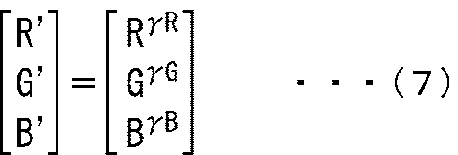
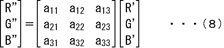
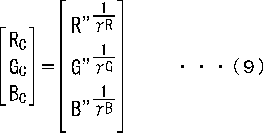
図27は、色ずれ補正情報の例を示す図である。
図28は、図26の合成装置400の合成処理を説明するフローチャートである。
図29は、変換部420の構成例を示すブロック図である。
(本開示を適用したコンピュータの説明)
上述した一連の処理は、ハードウエアにより実行することもできるし、ソフトウエアにより実行することもできる。一連の処理をソフトウエアにより実行する場合には、そのソフトウエアを構成するプログラムが、コンピュータにインストールされる。ここで、コンピュータには、専用のハードウエアに組み込まれているコンピュータや、各種のプログラムをインストールすることで、各種の機能を実行することが可能な、例えば汎用のパーソナルコンピュータなどが含まれる。
複数の第1の視点の2次元画像データから生成された被写体の3次元データから、所定の表示画像生成方式に対応する複数の第2の視点の2次元画像データと第3の視点に対する各画素の被写体の奥行き方向の位置を示すデプス画像データとを生成する2次元データ生成部と、
前記2次元データ生成部により生成された前記複数の第2の視点の2次元画像データと前記デプス画像データを符号化する符号化部と、
前記符号化部により符号化された前記複数の第2の視点の2次元画像データと前記デプス画像データを伝送する伝送部と
を備える符号化装置。
(2)
前記複数の第1の視点と前記複数の第2の視点とは異なる
ように構成された
前記(1)に記載の符号化装置。
(3)
前記複数の第2の視点は、同一円上に等間隔に存在する
ように構成された
前記(1)または(2)に記載の符号化装置。
(4)
前記複数の第2の視点のうちの少なくも2つの視点は、略水平方向に並ぶ
ように構成された
前記(1)または(2)に記載の符号化装置。
(5)
前記伝送部は、前記複数の第2の視点のうちの水平方向に並ぶ2つの視点を特定する情報を伝送する
ように構成された
前記(4)に記載の符号化装置。
(6)
前記伝送部は、前記複数の第2の視点の2次元画像データにおけるオクルージョン領域の前記3次元データを伝送する
ように構成された
前記(1)乃至(5)のいずれかに記載の符号化装置。
(7)
前記2次元データ生成部は、前記複数の第2の視点のカメラパラメータに基づいて、前記3次元データから前記複数の第2の視点の2次元画像データを生成し、前記第3の視点のカメラパラメータに基づいて、前記デプス画像データを生成し、
前記伝送部は、前記複数の第2の視点および前記第3の視点の前記カメラパラメータを伝送する
ように構成された
前記(1)乃至(6)のいずれかに記載の符号化装置。
(8)
前記所定の表示画像生成方式の数は、複数である
ように構成された
前記(1)乃至(7)のいずれかに記載の符号化装置。
(9)
前記複数の第2の視点と前記第3の視点は同一である
ように構成された
前記(1)乃至(8)のいずれかに記載の符号化装置。
(10)
符号化装置が、
複数の第1の視点の2次元画像データから生成された被写体の3次元データから、所定の表示画像生成方式に対応する複数の第2の視点の2次元画像データと第3の視点に対する各画素の被写体の奥行き方向の位置を示すデプス画像データとを生成する2次元データ生成ステップと、
前記2次元データ生成ステップの処理により生成された前記複数の第2の視点の2次元画像データと前記デプス画像データを符号化する符号化ステップと、
前記符号化ステップの処理により符号化された前記複数の第2の視点の2次元画像データと前記デプス画像データを伝送する伝送ステップと
を含む符号化方法。
(11)
所定の表示画像生成方式に対応する複数の第1の視点の2次元画像データの符号化データと、第2の視点に対する各画素の被写体の奥行き方向の位置を示すデプス画像データの符号化データとを復号する復号部と、
前記復号部による復号の結果得られる前記複数の第1の視点の第2次元画像データと前記デプス画像データとを用いて、被写体の3次元データを生成する3次元データ生成部と、
前記3次元データ生成部により生成された前記3次元データに基づいて、前記所定の表示画像生成方式で2次元画像データを表示画像データとして生成する2次元データ生成部と
を備える復号装置。
(12)
前記複数の第1の視点は、同一円上に等間隔に存在する
ように構成された
前記(11)に記載の復号装置。
(13)
前記複数の第1の視点のうちの少なくも2つの視点は、略水平方向に並ぶ
ように構成された
前記(11)に記載の復号装置。
(14)
前記複数の第1の視点のうちの水平方向に並ぶ2つの視点を特定する情報を受け取る受け取り部
をさらに備える
前記(13)に記載の復号装置。
(15)
前記複数の第1の視点の2次元画像データと前記デプス画像データは、複数の第3の視点の2次元画像データから生成された被写体の3次元データから生成される
ように構成された
前記(11)乃至(14)のいずれかに記載の復号装置。
(16)
前記3次元データ生成部は、前記複数の第1の視点の2次元画像データ、前記デプス画像データ、および前記複数の第1の視点の2次元画像データにおけるオクルージョン領域の3次元データを用いて、前記被写体の3次元データを生成する
ように構成された
前記(15)に記載の復号装置。
(17)
前記3次元データ生成部は、前記複数の第1の視点および前記第2の視点のカメラパラメータに基づいて、前記被写体の3次元データを生成する
ように構成された
前記(11)乃至(16)のいずれかに記載の復号装置。
(18)
前記所定の表示画像生成方式の数は、複数である
ように構成された
前記(11)乃至(17)のいずれかに記載の復号装置。
(19)
前記複数の第1の視点と前記第2の視点は同一である
ように構成された
前記(11)乃至(18)のいずれかに記載の復号装置。
(20)
復号装置が、
所定の表示画像生成方式に対応する複数の第1の視点の2次元画像データの符号化データと、第2の視点に対する各画素の被写体の奥行き方向の位置を示すデプス画像データの符号化データとを復号する復号ステップと、
前記復号ステップの処理による復号の結果得られる前記複数の第1の視点の第2次元画像データと前記デプス画像データとを用いて、被写体の3次元データを生成する3次元データ生成ステップと、
前記3次元データ生成ステップの処理により生成された前記3次元データに基づいて、前記所定の表示画像生成方式で2次元画像データを表示画像データとして生成する2次元データ生成ステップと
を含む復号方法。
Claims (20)
- 複数の第1の視点の2次元画像データから生成された被写体の3次元データから、所定の表示画像生成方式に対応する複数の第2の視点の2次元画像データと第3の視点に対する各画素の被写体の奥行き方向の位置を示すデプス画像データとを生成する2次元データ生成部と、
前記2次元データ生成部により生成された前記複数の第2の視点の2次元画像データと前記デプス画像データを符号化する符号化部と、
前記符号化部により符号化された前記複数の第2の視点の2次元画像データと前記デプス画像データを伝送する伝送部と
を備える符号化装置。 - 前記複数の第1の視点と前記複数の第2の視点とは異なる
ように構成された
請求項1に記載の符号化装置。 - 前記複数の第2の視点は、同一円上に等間隔に存在する
ように構成された
請求項1に記載の符号化装置。 - 前記複数の第2の視点のうちの少なくも2つの視点は、略水平方向に並ぶ
ように構成された
請求項1に記載の符号化装置。 - 前記伝送部は、前記複数の第2の視点のうちの水平方向に並ぶ2つの視点を特定する情報を伝送する
ように構成された
請求項4に記載の符号化装置。 - 前記伝送部は、前記複数の第2の視点の2次元画像データにおけるオクルージョン領域の前記3次元データを伝送する
ように構成された
請求項1に記載の符号化装置。 - 前記2次元データ生成部は、前記複数の第2の視点のカメラパラメータに基づいて、前記3次元データから前記複数の第2の視点の2次元画像データを生成し、前記第3の視点のカメラパラメータに基づいて、前記デプス画像データを生成し、
前記伝送部は、前記複数の第2の視点および前記第3の視点の前記カメラパラメータを伝送する
ように構成された
請求項1に記載の符号化装置。 - 前記所定の表示画像生成方式の数は、複数である
ように構成された
請求項1に記載の符号化装置。 - 前記複数の第2の視点と前記第3の視点は同一である
ように構成された
請求項1に記載の符号化装置。 - 符号化装置が、
複数の第1の視点の2次元画像データから生成された被写体の3次元データから、所定の表示画像生成方式に対応する複数の第2の視点の2次元画像データと第3の視点に対する各画素の被写体の奥行き方向の位置を示すデプス画像データとを生成する2次元データ生成ステップと、
前記2次元データ生成ステップの処理により生成された前記複数の第2の視点の2次元画像データと前記デプス画像データを符号化する符号化ステップと、
前記符号化ステップの処理により符号化された前記複数の第2の視点の2次元画像データと前記デプス画像データを伝送する伝送ステップと
を含む符号化方法。 - 所定の表示画像生成方式に対応する複数の第1の視点の2次元画像データの符号化データと、第2の視点に対する各画素の被写体の奥行き方向の位置を示すデプス画像データの符号化データとを復号する復号部と、
前記復号部による復号の結果得られる前記複数の第1の視点の第2次元画像データと前記デプス画像データとを用いて、被写体の3次元データを生成する3次元データ生成部と、
前記3次元データ生成部により生成された前記3次元データに基づいて、前記所定の表示画像生成方式で2次元画像データを表示画像データとして生成する2次元データ生成部と
を備える復号装置。 - 前記複数の第1の視点は、同一円上に等間隔に存在する
ように構成された
請求項11に記載の復号装置。 - 前記複数の第1の視点のうちの少なくも2つの視点は、略水平方向に並ぶ
ように構成された
請求項11に記載の復号装置。 - 前記複数の第1の視点のうちの水平方向に並ぶ2つの視点を特定する情報を受け取る受け取り部
をさらに備える
請求項13に記載の復号装置。 - 前記複数の第1の視点の2次元画像データと前記デプス画像データは、複数の第3の視点の2次元画像データから生成された被写体の3次元データから生成される
ように構成された
請求項11に記載の復号装置。 - 前記3次元データ生成部は、前記複数の第1の視点の2次元画像データ、前記デプス画像データ、および前記複数の第1の視点の2次元画像データにおけるオクルージョン領域の3次元データを用いて、前記被写体の3次元データを生成する
ように構成された
請求項15に記載の復号装置。 - 前記3次元データ生成部は、前記複数の第1の視点および前記第2の視点のカメラパラメータに基づいて、前記被写体の3次元データを生成する
ように構成された
請求項11に記載の復号装置。 - 前記所定の表示画像生成方式の数は、複数である
ように構成された
請求項11に記載の復号装置。 - 前記複数の第1の視点と前記第2の視点は同一である
ように構成された
請求項11に記載の復号装置。 - 復号装置が、
所定の表示画像生成方式に対応する複数の第1の視点の2次元画像データの符号化データと、第2の視点に対する各画素の被写体の奥行き方向の位置を示すデプス画像データの符号化データとを復号する復号ステップと、
前記復号ステップの処理による復号の結果得られる前記複数の第1の視点の第2次元画像データと前記デプス画像データとを用いて、被写体の3次元データを生成する3次元データ生成ステップと、
前記3次元データ生成ステップの処理により生成された前記3次元データに基づいて、前記所定の表示画像生成方式で2次元画像データを表示画像データとして生成する2次元データ生成ステップと
を含む復号方法。
Priority Applications (16)
| Application Number | Priority Date | Filing Date | Title |
|---|---|---|---|
| RU2018116473A RU2721678C2 (ru) | 2015-11-11 | 2016-10-28 | Устройство кодирования и способ кодирования, устройство декодирования и способ декодирования |
| EP16864039.9A EP3343914A4 (en) | 2015-11-11 | 2016-10-28 | ENCLOSURE DEVICE AND ENCLOSURE METHOD AND DECOMPOSITION DEVICE AND DECOMPOSITION METHOD |
| AU2016352648A AU2016352648A1 (en) | 2015-11-11 | 2016-10-28 | Encoding device and encoding method, and decoding device and decoding method |
| MYPI2018000679A MY202620A (en) | 2015-11-11 | 2016-10-28 | Encoding apparatus and encoding method, decoding apparatus and decoding method |
| SG11201803682RA SG11201803682RA (en) | 2015-11-11 | 2016-10-28 | Encoding apparatus and encoding method, decoding apparatus and decoding method |
| KR1020187012316A KR102516992B1 (ko) | 2015-11-11 | 2016-10-28 | 부호화 장치 및 부호화 방법, 복호 장치 및 복호 방법 |
| CN201680064678.3A CN108353157B (zh) | 2015-11-11 | 2016-10-28 | 编码设备和编码方法以及解码设备和解码方法 |
| CN202110383257.XA CN113286137B (zh) | 2015-11-11 | 2016-10-28 | 编码设备和编码方法以及解码设备和解码方法 |
| MX2018005501A MX389538B (es) | 2015-11-11 | 2016-10-28 | Dispositivo de codificación y método de codificación, aparato de decodificación y método de decodificación. |
| US15/765,805 US11716487B2 (en) | 2015-11-11 | 2016-10-28 | Encoding apparatus and encoding method, decoding apparatus and decoding method |
| BR112018009070A BR112018009070A8 (pt) | 2015-11-11 | 2016-10-28 | aparelhos de codificação e de decodificação, e, métodos para codificação por um aparelho de codificação e para decodificação por um aparelho de decodificação. |
| CA3004241A CA3004241C (en) | 2015-11-11 | 2016-10-28 | Encoding apparatus and encoding method, decoding apparatus and decoding method |
| JP2017550061A JP6384744B2 (ja) | 2015-11-11 | 2016-10-28 | 符号化装置および符号化方法 |
| ZA2018/02193A ZA201802193B (en) | 2015-11-11 | 2018-04-04 | Encoding device and encoding method, and decoding device and decoding method |
| PH12018500977A PH12018500977A1 (en) | 2015-11-11 | 2018-05-04 | Encoding device and encoding method, and decoding device and decoding method |
| AU2021203450A AU2021203450B2 (en) | 2015-11-11 | 2021-05-27 | Encoding device and encoding method, and decoding device and decoding method |
Applications Claiming Priority (2)
| Application Number | Priority Date | Filing Date | Title |
|---|---|---|---|
| JP2015-221233 | 2015-11-11 | ||
| JP2015221233 | 2015-11-11 |
Publications (1)
| Publication Number | Publication Date |
|---|---|
| WO2017082076A1 true WO2017082076A1 (ja) | 2017-05-18 |
Family
ID=58695131
Family Applications (1)
| Application Number | Title | Priority Date | Filing Date |
|---|---|---|---|
| PCT/JP2016/082024 Ceased WO2017082076A1 (ja) | 2015-11-11 | 2016-10-28 | 符号化装置および符号化方法、復号装置および復号方法 |
Country Status (14)
| Country | Link |
|---|---|
| US (1) | US11716487B2 (ja) |
| EP (1) | EP3343914A4 (ja) |
| JP (3) | JP6384744B2 (ja) |
| KR (1) | KR102516992B1 (ja) |
| CN (2) | CN113286137B (ja) |
| AU (2) | AU2016352648A1 (ja) |
| BR (1) | BR112018009070A8 (ja) |
| MX (1) | MX389538B (ja) |
| MY (1) | MY202620A (ja) |
| PH (1) | PH12018500977A1 (ja) |
| RU (1) | RU2721678C2 (ja) |
| SG (1) | SG11201803682RA (ja) |
| WO (1) | WO2017082076A1 (ja) |
| ZA (1) | ZA201802193B (ja) |
Cited By (15)
| Publication number | Priority date | Publication date | Assignee | Title |
|---|---|---|---|---|
| CN108769643A (zh) * | 2018-06-15 | 2018-11-06 | 深圳超多维科技有限公司 | 视频拍摄方法、装置及系统 |
| WO2019031259A1 (ja) * | 2017-08-08 | 2019-02-14 | ソニー株式会社 | 画像処理装置および方法 |
| WO2019167300A1 (en) | 2018-03-01 | 2019-09-06 | Sony Corporation | Image processing device, encoding device, decoding device, image processing method, program, encoding method, and decoding method |
| WO2020008758A1 (ja) * | 2018-07-06 | 2020-01-09 | ソニー株式会社 | 情報処理装置および情報処理方法、並びにプログラム |
| WO2020105422A1 (en) | 2018-11-20 | 2020-05-28 | Sony Corporation | Image processing device, image processing method, program, and display device |
| WO2020121844A1 (en) | 2018-12-12 | 2020-06-18 | Sony Corporation | Image processing device, image processing method, and program |
| WO2020137584A1 (ja) | 2018-12-25 | 2020-07-02 | ソニー株式会社 | 映像再生装置、再生方法、およびプログラム |
| JP2020522802A (ja) * | 2017-05-31 | 2020-07-30 | ベライゾン・パテント・アンド・ライセンシング・インコーポレイテッドVerizon Patent And Licensing Inc. | 異なる複数のヴァンテージ・ポイントから、バーチャル・シーンのバーチャル・エンティティ記述フレームに基づいて、バーチャル・シーンのフレームをレンダリングする方法及びシステム |
| JP2020522801A (ja) * | 2017-05-31 | 2020-07-30 | ベライゾン・パテント・アンド・ライセンシング・インコーポレイテッドVerizon Patent And Licensing Inc. | バーチャル・リアリティ・メディア・コンテンツ内に含める目的での現実世界シーンのカスタマイズされるビューの仮想化プロジェクションを生成するための方法及びシステム |
| WO2020262261A1 (ja) | 2019-06-28 | 2020-12-30 | ソニー株式会社 | 情報処理装置、情報処理方法及びプログラム |
| WO2021079592A1 (ja) | 2019-10-21 | 2021-04-29 | ソニー株式会社 | 情報処理装置、3dデータの生成方法及びプログラム |
| WO2021187093A1 (ja) | 2020-03-17 | 2021-09-23 | ソニーグループ株式会社 | 画像処理装置、および、動画像データ生成方法 |
| WO2022024780A1 (ja) * | 2020-07-30 | 2022-02-03 | ソニーグループ株式会社 | 情報処理装置、情報処理方法、映像配信方法及び情報処理システム |
| US11557087B2 (en) | 2018-12-19 | 2023-01-17 | Sony Group Corporation | Image processing apparatus and image processing method for generating a strobe image using a three-dimensional model of an object |
| JP2024040313A (ja) * | 2019-06-11 | 2024-03-25 | 株式会社Mujin | 第1のカメラによって生成された第1の画像を第2のカメラによって生成された第2の画像に基づいて更新する方法及び処理システム |
Families Citing this family (10)
| Publication number | Priority date | Publication date | Assignee | Title |
|---|---|---|---|---|
| CN110876050B (zh) * | 2018-08-31 | 2021-08-20 | 盎锐(上海)信息科技有限公司 | 基于3d摄像机的数据处理装置及方法 |
| CN111669570B (zh) * | 2019-03-07 | 2023-12-19 | 阿里巴巴集团控股有限公司 | 多角度自由视角视频数据处理方法及装置、介质、设备 |
| US11341715B2 (en) | 2019-03-07 | 2022-05-24 | Alibaba Group Holding Limited | Video reconstruction method, system, device, and computer readable storage medium |
| US12136243B2 (en) * | 2019-03-20 | 2024-11-05 | Interdigital Vc Holdings, Inc. | Processing missing points of a point cloud |
| WO2021022266A2 (en) * | 2019-10-07 | 2021-02-04 | Futurewei Technologies, Inc. | Video-based point cloud compression (v-pcc) timing information |
| CN112788325B (zh) * | 2019-11-06 | 2023-06-02 | Oppo广东移动通信有限公司 | 一种图像处理方法、编码装置、解码装置及存储介质 |
| JP2021099430A (ja) * | 2019-12-23 | 2021-07-01 | セイコーエプソン株式会社 | 表示装置の制御方法及び表示装置 |
| KR102242710B1 (ko) * | 2019-12-31 | 2021-04-22 | 서울과학기술대학교 산학협력단 | 반자유 시점 영상을 제공하는 장치 |
| CN114926605B (zh) * | 2022-07-19 | 2022-09-30 | 北京飞渡科技有限公司 | 一种三维模型的抽壳方法 |
| CN117671402A (zh) * | 2022-08-22 | 2024-03-08 | 华为技术有限公司 | 识别模型训练方法、装置以及可移动智能设备 |
Citations (5)
| Publication number | Priority date | Publication date | Assignee | Title |
|---|---|---|---|---|
| JP2010157825A (ja) * | 2008-12-26 | 2010-07-15 | Victor Co Of Japan Ltd | 画像符号化装置、画像符号化方法およびそのプログラム |
| JP2010531604A (ja) * | 2007-06-26 | 2010-09-24 | コーニンクレッカ フィリップス エレクトロニクス エヌ ヴィ | 3次元ビデオ信号をエンコードするための方法及びシステム、含まれる3次元ビデオ信号、並びに3次元ビデオ信号のためのデコーダのための方法及び信号 |
| JP2011519227A (ja) * | 2008-04-25 | 2011-06-30 | トムソン ライセンシング | 奥行き信号の符号化 |
| JP2012023488A (ja) * | 2010-07-13 | 2012-02-02 | Ntt Docomo Inc | 画像処理装置、画像処理方法、表示装置及びプログラム |
| JP2012518367A (ja) * | 2009-02-19 | 2012-08-09 | トムソン ライセンシング | 3d映像フォーマット |
Family Cites Families (23)
| Publication number | Priority date | Publication date | Assignee | Title |
|---|---|---|---|---|
| JP3231618B2 (ja) * | 1996-04-23 | 2001-11-26 | 日本電気株式会社 | 3次元画像符号化復号方式 |
| US6573912B1 (en) * | 2000-11-07 | 2003-06-03 | Zaxel Systems, Inc. | Internet system for virtual telepresence |
| US20050185711A1 (en) * | 2004-02-20 | 2005-08-25 | Hanspeter Pfister | 3D television system and method |
| US8244025B2 (en) * | 2006-03-20 | 2012-08-14 | Siemens Energy, Inc. | Method of coalescing information about inspected objects |
| CN101453662B (zh) * | 2007-12-03 | 2012-04-04 | 华为技术有限公司 | 立体视频通信终端、系统及方法 |
| CN101472190B (zh) * | 2007-12-28 | 2013-01-23 | 华为终端有限公司 | 多视角摄像及图像处理装置、系统 |
| JP5035195B2 (ja) | 2008-09-25 | 2012-09-26 | Kddi株式会社 | 画像生成装置及びプログラム |
| EP2197217A1 (en) * | 2008-12-15 | 2010-06-16 | Koninklijke Philips Electronics N.V. | Image based 3D video format |
| US8750632B2 (en) | 2008-12-26 | 2014-06-10 | JVC Kenwood Corporation | Apparatus and method for encoding images from multiple viewpoints and associated depth information |
| JP2010157821A (ja) * | 2008-12-26 | 2010-07-15 | Victor Co Of Japan Ltd | 画像符号化装置、画像符号化方法およびそのプログラム |
| JP2010157823A (ja) | 2008-12-26 | 2010-07-15 | Victor Co Of Japan Ltd | 画像符号化装置、画像符号化方法およびそのプログラム |
| US9124874B2 (en) * | 2009-06-05 | 2015-09-01 | Qualcomm Incorporated | Encoding of three-dimensional conversion information with two-dimensional video sequence |
| KR101694821B1 (ko) * | 2010-01-28 | 2017-01-11 | 삼성전자주식회사 | 다시점 비디오스트림에 대한 링크 정보를 이용하는 디지털 데이터스트림 전송 방법와 그 장치, 및 링크 정보를 이용하는 디지털 데이터스트림 전송 방법과 그 장치 |
| HU1000640D0 (en) * | 2010-11-29 | 2011-02-28 | Holografika Hologrameloeallito Fejlesztoe Es Forgalmazo Kft | Image coding and decoding method and apparatus for efficient encoding and decoding of 3d field content |
| WO2012101582A1 (en) * | 2011-01-24 | 2012-08-02 | Invision Biometrics Ltd. | Method and system for acquisition, representation, compression, and transmission of three-dimensional data |
| CN102724520A (zh) | 2011-03-29 | 2012-10-10 | 青岛海信电器股份有限公司 | 视频处理方法和系统 |
| US20120314031A1 (en) * | 2011-06-07 | 2012-12-13 | Microsoft Corporation | Invariant features for computer vision |
| US9351028B2 (en) | 2011-07-14 | 2016-05-24 | Qualcomm Incorporated | Wireless 3D streaming server |
| JP2013211777A (ja) * | 2012-03-30 | 2013-10-10 | Sharp Corp | 画像符号化装置、画像復号装置、画像符号化方法、画像復号方法およびプログラム |
| KR102126532B1 (ko) * | 2013-09-30 | 2020-06-24 | 엘지디스플레이 주식회사 | 멀티뷰 영상 생성 방법과 이를 이용한 입체 영상 표시 장치 |
| GB2525170A (en) | 2014-04-07 | 2015-10-21 | Nokia Technologies Oy | Stereo viewing |
| EP3175200A4 (en) * | 2014-07-31 | 2018-04-04 | Hewlett-Packard Development Company, L.P. | Three dimensional scanning system and framework |
| US20170004647A1 (en) * | 2015-06-30 | 2017-01-05 | Microsoft Technology Licensing, Llc | Rendering graphics data on demand |
-
2016
- 2016-10-28 US US15/765,805 patent/US11716487B2/en active Active
- 2016-10-28 JP JP2017550061A patent/JP6384744B2/ja active Active
- 2016-10-28 RU RU2018116473A patent/RU2721678C2/ru active
- 2016-10-28 AU AU2016352648A patent/AU2016352648A1/en not_active Abandoned
- 2016-10-28 KR KR1020187012316A patent/KR102516992B1/ko active Active
- 2016-10-28 CN CN202110383257.XA patent/CN113286137B/zh active Active
- 2016-10-28 WO PCT/JP2016/082024 patent/WO2017082076A1/ja not_active Ceased
- 2016-10-28 SG SG11201803682RA patent/SG11201803682RA/en unknown
- 2016-10-28 MX MX2018005501A patent/MX389538B/es unknown
- 2016-10-28 BR BR112018009070A patent/BR112018009070A8/pt not_active Application Discontinuation
- 2016-10-28 CN CN201680064678.3A patent/CN108353157B/zh active Active
- 2016-10-28 MY MYPI2018000679A patent/MY202620A/en unknown
- 2016-10-28 EP EP16864039.9A patent/EP3343914A4/en not_active Ceased
-
2018
- 2018-04-04 ZA ZA2018/02193A patent/ZA201802193B/en unknown
- 2018-05-04 PH PH12018500977A patent/PH12018500977A1/en unknown
- 2018-07-20 JP JP2018136595A patent/JP6872131B2/ja active Active
-
2021
- 2021-01-13 JP JP2021003267A patent/JP7143905B2/ja active Active
- 2021-05-27 AU AU2021203450A patent/AU2021203450B2/en active Active
Patent Citations (5)
| Publication number | Priority date | Publication date | Assignee | Title |
|---|---|---|---|---|
| JP2010531604A (ja) * | 2007-06-26 | 2010-09-24 | コーニンクレッカ フィリップス エレクトロニクス エヌ ヴィ | 3次元ビデオ信号をエンコードするための方法及びシステム、含まれる3次元ビデオ信号、並びに3次元ビデオ信号のためのデコーダのための方法及び信号 |
| JP2011519227A (ja) * | 2008-04-25 | 2011-06-30 | トムソン ライセンシング | 奥行き信号の符号化 |
| JP2010157825A (ja) * | 2008-12-26 | 2010-07-15 | Victor Co Of Japan Ltd | 画像符号化装置、画像符号化方法およびそのプログラム |
| JP2012518367A (ja) * | 2009-02-19 | 2012-08-09 | トムソン ライセンシング | 3d映像フォーマット |
| JP2012023488A (ja) * | 2010-07-13 | 2012-02-02 | Ntt Docomo Inc | 画像処理装置、画像処理方法、表示装置及びプログラム |
Non-Patent Citations (1)
| Title |
|---|
| See also references of EP3343914A4 * |
Cited By (29)
| Publication number | Priority date | Publication date | Assignee | Title |
|---|---|---|---|---|
| JP2020522802A (ja) * | 2017-05-31 | 2020-07-30 | ベライゾン・パテント・アンド・ライセンシング・インコーポレイテッドVerizon Patent And Licensing Inc. | 異なる複数のヴァンテージ・ポイントから、バーチャル・シーンのバーチャル・エンティティ記述フレームに基づいて、バーチャル・シーンのフレームをレンダリングする方法及びシステム |
| JP7194125B2 (ja) | 2017-05-31 | 2022-12-21 | ベライゾン・パテント・アンド・ライセンシング・インコーポレイテッド | バーチャル・リアリティ・メディア・コンテンツ内に含める目的での現実世界シーンのカスタマイズされるビューの仮想化プロジェクションを生成するための方法及びシステム |
| JP7194126B2 (ja) | 2017-05-31 | 2022-12-21 | ベライゾン・パテント・アンド・ライセンシング・インコーポレイテッド | 異なる複数のヴァンテージ・ポイントから、バーチャル・シーンのバーチャル・エンティティ記述フレームに基づいて、バーチャル・シーンのフレームをレンダリングする方法及びシステム |
| JP2020522801A (ja) * | 2017-05-31 | 2020-07-30 | ベライゾン・パテント・アンド・ライセンシング・インコーポレイテッドVerizon Patent And Licensing Inc. | バーチャル・リアリティ・メディア・コンテンツ内に含める目的での現実世界シーンのカスタマイズされるビューの仮想化プロジェクションを生成するための方法及びシステム |
| CN110998669A (zh) * | 2017-08-08 | 2020-04-10 | 索尼公司 | 图像处理装置和方法 |
| CN110998669B (zh) * | 2017-08-08 | 2023-12-08 | 索尼公司 | 图像处理装置和方法 |
| WO2019031259A1 (ja) * | 2017-08-08 | 2019-02-14 | ソニー株式会社 | 画像処理装置および方法 |
| JP7003994B2 (ja) | 2017-08-08 | 2022-01-21 | ソニーグループ株式会社 | 画像処理装置および方法 |
| JPWO2019031259A1 (ja) * | 2017-08-08 | 2020-09-10 | ソニー株式会社 | 画像処理装置および方法 |
| WO2019167300A1 (en) | 2018-03-01 | 2019-09-06 | Sony Corporation | Image processing device, encoding device, decoding device, image processing method, program, encoding method, and decoding method |
| CN108769643A (zh) * | 2018-06-15 | 2018-11-06 | 深圳超多维科技有限公司 | 视频拍摄方法、装置及系统 |
| US11516453B2 (en) | 2018-07-06 | 2022-11-29 | Sony Corporation | Information processing apparatus, information processing method, and program for point cloud sample processing |
| JP7310816B2 (ja) | 2018-07-06 | 2023-07-19 | ソニーグループ株式会社 | 情報処理装置および情報処理方法、並びにプログラム |
| JPWO2020008758A1 (ja) * | 2018-07-06 | 2021-07-08 | ソニーグループ株式会社 | 情報処理装置および情報処理方法、並びにプログラム |
| WO2020008758A1 (ja) * | 2018-07-06 | 2020-01-09 | ソニー株式会社 | 情報処理装置および情報処理方法、並びにプログラム |
| WO2020105422A1 (en) | 2018-11-20 | 2020-05-28 | Sony Corporation | Image processing device, image processing method, program, and display device |
| WO2020121844A1 (en) | 2018-12-12 | 2020-06-18 | Sony Corporation | Image processing device, image processing method, and program |
| US11557087B2 (en) | 2018-12-19 | 2023-01-17 | Sony Group Corporation | Image processing apparatus and image processing method for generating a strobe image using a three-dimensional model of an object |
| WO2020137584A1 (ja) | 2018-12-25 | 2020-07-02 | ソニー株式会社 | 映像再生装置、再生方法、およびプログラム |
| KR20210107631A (ko) | 2018-12-25 | 2021-09-01 | 소니그룹주식회사 | 영상 재생 장치, 재생 방법 및 프로그램 |
| US11825066B2 (en) | 2018-12-25 | 2023-11-21 | Sony Corporation | Video reproduction apparatus, reproduction method, and program |
| JP2024040313A (ja) * | 2019-06-11 | 2024-03-25 | 株式会社Mujin | 第1のカメラによって生成された第1の画像を第2のカメラによって生成された第2の画像に基づいて更新する方法及び処理システム |
| WO2020262261A1 (ja) | 2019-06-28 | 2020-12-30 | ソニー株式会社 | 情報処理装置、情報処理方法及びプログラム |
| US11842453B2 (en) | 2019-06-28 | 2023-12-12 | Sony Group Corporation | Information processing device, information processing method, and program |
| WO2021079592A1 (ja) | 2019-10-21 | 2021-04-29 | ソニー株式会社 | 情報処理装置、3dデータの生成方法及びプログラム |
| WO2021187093A1 (ja) | 2020-03-17 | 2021-09-23 | ソニーグループ株式会社 | 画像処理装置、および、動画像データ生成方法 |
| JPWO2022024780A1 (ja) * | 2020-07-30 | 2022-02-03 | ||
| WO2022024780A1 (ja) * | 2020-07-30 | 2022-02-03 | ソニーグループ株式会社 | 情報処理装置、情報処理方法、映像配信方法及び情報処理システム |
| US12260491B2 (en) | 2020-07-30 | 2025-03-25 | Sony Group Corporation | Information processing device, information processing method, video distribution method, and information processing system |
Also Published As
| Publication number | Publication date |
|---|---|
| BR112018009070A8 (pt) | 2019-02-26 |
| MY202620A (en) | 2024-05-10 |
| KR20180081720A (ko) | 2018-07-17 |
| JP7143905B2 (ja) | 2022-09-29 |
| BR112018009070A2 (ja) | 2018-10-30 |
| RU2721678C2 (ru) | 2020-05-21 |
| EP3343914A1 (en) | 2018-07-04 |
| AU2021203450A1 (en) | 2021-06-24 |
| SG11201803682RA (en) | 2018-06-28 |
| RU2018116473A (ru) | 2019-11-05 |
| CA3004241A1 (en) | 2017-05-18 |
| KR102516992B1 (ko) | 2023-04-04 |
| US11716487B2 (en) | 2023-08-01 |
| AU2016352648A1 (en) | 2018-05-10 |
| CN113286137B (zh) | 2024-02-02 |
| JP6384744B2 (ja) | 2018-09-05 |
| US20180302647A1 (en) | 2018-10-18 |
| MX389538B (es) | 2025-03-20 |
| MX2018005501A (es) | 2018-08-01 |
| AU2021203450B2 (en) | 2022-11-24 |
| RU2018116473A3 (ja) | 2019-11-05 |
| JPWO2017082076A1 (ja) | 2018-07-26 |
| CN113286137A (zh) | 2021-08-20 |
| CN108353157B (zh) | 2021-06-08 |
| EP3343914A4 (en) | 2019-04-10 |
| JP2018182755A (ja) | 2018-11-15 |
| ZA201802193B (en) | 2020-08-26 |
| CN108353157A (zh) | 2018-07-31 |
| JP2021072639A (ja) | 2021-05-06 |
| JP6872131B2 (ja) | 2021-05-19 |
| PH12018500977A1 (en) | 2019-01-28 |
Similar Documents
| Publication | Publication Date | Title |
|---|---|---|
| JP6384744B2 (ja) | 符号化装置および符号化方法 | |
| JP6911765B2 (ja) | 画像処理装置および画像処理方法 | |
| KR102527566B1 (ko) | 화상 처리 장치 및 화상 처리 방법 | |
| CN101651841B (zh) | 一种立体视频通讯的实现方法、系统和设备 | |
| JP7009996B2 (ja) | 画像処理装置および画像処理方法 | |
| KR101233399B1 (ko) | 다시점 깊이 영상 생성 방법 및 장치 | |
| CA3004241C (en) | Encoding apparatus and encoding method, decoding apparatus and decoding method | |
| JP6599634B2 (ja) | 多視点画像符号化装置、多視点画像復号装置、補助情報生成装置、画像復元装置及びプログラム |
Legal Events
| Date | Code | Title | Description |
|---|---|---|---|
| 121 | Ep: the epo has been informed by wipo that ep was designated in this application |
Ref document number: 16864039 Country of ref document: EP Kind code of ref document: A1 |
|
| ENP | Entry into the national phase |
Ref document number: 2017550061 Country of ref document: JP Kind code of ref document: A |
|
| WWE | Wipo information: entry into national phase |
Ref document number: 2016864039 Country of ref document: EP |
|
| WWE | Wipo information: entry into national phase |
Ref document number: 15765805 Country of ref document: US |
|
| ENP | Entry into the national phase |
Ref document number: 20187012316 Country of ref document: KR Kind code of ref document: A |
|
| WWE | Wipo information: entry into national phase |
Ref document number: MX/A/2018/005501 Country of ref document: MX |
|
| ENP | Entry into the national phase |
Ref document number: 3004241 Country of ref document: CA |
|
| WWE | Wipo information: entry into national phase |
Ref document number: 11201803682R Country of ref document: SG Ref document number: 2018116473 Country of ref document: RU Ref document number: 12018500977 Country of ref document: PH |
|
| ENP | Entry into the national phase |
Ref document number: 2016352648 Country of ref document: AU Date of ref document: 20161028 Kind code of ref document: A |
|
| NENP | Non-entry into the national phase |
Ref country code: DE |
|
| REG | Reference to national code |
Ref country code: BR Ref legal event code: B01A Ref document number: 112018009070 Country of ref document: BR |
|
| ENP | Entry into the national phase |
Ref document number: 112018009070 Country of ref document: BR Kind code of ref document: A2 Effective date: 20180504 |