WO2017082248A1 - 船舶推進装置 - Google Patents
船舶推進装置 Download PDFInfo
- Publication number
- WO2017082248A1 WO2017082248A1 PCT/JP2016/083102 JP2016083102W WO2017082248A1 WO 2017082248 A1 WO2017082248 A1 WO 2017082248A1 JP 2016083102 W JP2016083102 W JP 2016083102W WO 2017082248 A1 WO2017082248 A1 WO 2017082248A1
- Authority
- WO
- WIPO (PCT)
- Prior art keywords
- duct
- propulsion device
- marine vessel
- casing
- vessel propulsion
- Prior art date
- Legal status (The legal status is an assumption and is not a legal conclusion. Google has not performed a legal analysis and makes no representation as to the accuracy of the status listed.)
- Ceased
Links
Images


Classifications
-
- B—PERFORMING OPERATIONS; TRANSPORTING
- B63—SHIPS OR OTHER WATERBORNE VESSELS; RELATED EQUIPMENT
- B63H—MARINE PROPULSION OR STEERING
- B63H5/00—Arrangements on vessels of propulsion elements directly acting on water
- B63H5/07—Arrangements on vessels of propulsion elements directly acting on water of propellers
- B63H5/125—Arrangements on vessels of propulsion elements directly acting on water of propellers movably mounted with respect to hull, e.g. adjustable in direction, e.g. podded azimuthing thrusters
-
- B—PERFORMING OPERATIONS; TRANSPORTING
- B63—SHIPS OR OTHER WATERBORNE VESSELS; RELATED EQUIPMENT
- B63H—MARINE PROPULSION OR STEERING
- B63H1/00—Propulsive elements directly acting on water
- B63H1/02—Propulsive elements directly acting on water of rotary type
- B63H1/12—Propulsive elements directly acting on water of rotary type with rotation axis substantially in propulsive direction
- B63H1/14—Propellers
- B63H1/16—Propellers having a shrouding ring attached to blades
-
- B—PERFORMING OPERATIONS; TRANSPORTING
- B63—SHIPS OR OTHER WATERBORNE VESSELS; RELATED EQUIPMENT
- B63H—MARINE PROPULSION OR STEERING
- B63H20/00—Outboard propulsion units, e.g. outboard motors or Z-drives; Arrangements thereof on vessels
- B63H20/007—Trolling propulsion units
-
- B—PERFORMING OPERATIONS; TRANSPORTING
- B63—SHIPS OR OTHER WATERBORNE VESSELS; RELATED EQUIPMENT
- B63H—MARINE PROPULSION OR STEERING
- B63H20/00—Outboard propulsion units, e.g. outboard motors or Z-drives; Arrangements thereof on vessels
- B63H20/02—Mounting of propulsion units
- B63H20/06—Mounting of propulsion units on an intermediate support
-
- B—PERFORMING OPERATIONS; TRANSPORTING
- B63—SHIPS OR OTHER WATERBORNE VESSELS; RELATED EQUIPMENT
- B63H—MARINE PROPULSION OR STEERING
- B63H23/00—Transmitting power from propulsion power plant to propulsive elements
- B63H23/22—Transmitting power from propulsion power plant to propulsive elements with non-mechanical gearing
- B63H23/24—Transmitting power from propulsion power plant to propulsive elements with non-mechanical gearing electric
-
- B—PERFORMING OPERATIONS; TRANSPORTING
- B63—SHIPS OR OTHER WATERBORNE VESSELS; RELATED EQUIPMENT
- B63H—MARINE PROPULSION OR STEERING
- B63H1/00—Propulsive elements directly acting on water
- B63H1/02—Propulsive elements directly acting on water of rotary type
- B63H1/12—Propulsive elements directly acting on water of rotary type with rotation axis substantially in propulsive direction
- B63H1/14—Propellers
- B63H1/16—Propellers having a shrouding ring attached to blades
- B63H2001/165—Hubless propellers, e.g. peripherally driven shrouds with blades projecting from the shrouds' inside surfaces
-
- B—PERFORMING OPERATIONS; TRANSPORTING
- B63—SHIPS OR OTHER WATERBORNE VESSELS; RELATED EQUIPMENT
- B63H—MARINE PROPULSION OR STEERING
- B63H5/00—Arrangements on vessels of propulsion elements directly acting on water
- B63H5/07—Arrangements on vessels of propulsion elements directly acting on water of propellers
- B63H5/125—Arrangements on vessels of propulsion elements directly acting on water of propellers movably mounted with respect to hull, e.g. adjustable in direction, e.g. podded azimuthing thrusters
- B63H2005/1254—Podded azimuthing thrusters, i.e. podded thruster units arranged inboard for rotation about vertical axis
- B63H2005/1258—Podded azimuthing thrusters, i.e. podded thruster units arranged inboard for rotation about vertical axis with electric power transmission to propellers, i.e. with integrated electric propeller motors
-
- B—PERFORMING OPERATIONS; TRANSPORTING
- B63—SHIPS OR OTHER WATERBORNE VESSELS; RELATED EQUIPMENT
- B63H—MARINE PROPULSION OR STEERING
- B63H23/00—Transmitting power from propulsion power plant to propulsive elements
- B63H2023/005—Transmitting power from propulsion power plant to propulsive elements using a drive acting on the periphery of a rotating propulsive element, e.g. on a dented circumferential ring on a propeller, or a propeller acting as rotor of an electric motor
-
- B—PERFORMING OPERATIONS; TRANSPORTING
- B63—SHIPS OR OTHER WATERBORNE VESSELS; RELATED EQUIPMENT
- B63H—MARINE PROPULSION OR STEERING
- B63H21/00—Use of propulsion power plant or units on vessels
- B63H21/12—Use of propulsion power plant or units on vessels the vessels being motor-driven
- B63H21/17—Use of propulsion power plant or units on vessels the vessels being motor-driven by electric motor
Definitions
- This invention relates to a ship propulsion device.
- ship propulsion devices are known. For example, it is disclosed in JP2013-100013A.
- the above Japanese Unexamined Patent Publication No. 2013-100013 includes a duct in which a stator is disposed, a rim in which a rotor is disposed at a position facing the stator, and a blade formed radially inward of the rim.
- a marine vessel propulsion device is disclosed that includes a propeller, a steering shaft that supports a duct so as to be steerable, and a motor ECU that controls rotational driving of the propeller.
- the motor ECU of this marine vessel propulsion device is arranged inside the steering shaft or in the vessel.
- the present invention has been made to solve the above-described problems, and one object of the present invention is to suppress the increase in size of the apparatus while suppressing the wiring from becoming complicated. It is to provide a possible ship propulsion device.
- a marine vessel propulsion device includes a duct including a stator portion, a rim having a rotor portion disposed at a position facing the stator portion, and blades formed radially inward of the rim.
- a propeller portion a steering shaft that supports the duct so as to be steerable, a steering shaft that is provided separately from the steering shaft and that extends along the rotation axis direction of the propeller portion, and is disposed in the casing portion; And a motor control unit that controls rotation driving of the propeller unit.
- the rotation drive of the propeller unit is controlled in the casing unit that is provided separately from the steering shaft and extends along the rotation axis direction of the propeller unit.
- a motor control unit is arranged.
- a marine vessel propulsion apparatus that can suppress the increase in size of the apparatus while suppressing complicated wiring.
- the casing part By forming the casing part so as to extend along the direction of the rotation axis of the propeller part, it is possible to suppress an increase in water resistance. Can do. Since a casing part can be arrange
- the casing part is preferably fixed to the duct so as to be steerable together with the duct. If comprised in this way, since a duct and a casing part are steered integrally, even when a duct is steered, it can suppress that resistance of water resulting from a casing part becomes large.
- the casing part is provided integrally with the duct. If comprised in this way, compared with the case where a duct and a casing part are provided separately, while being able to reduce a number of parts, the joint surface of a duct and a casing part can be eliminated, so that flooding is effective. Can be suppressed.
- the casing portion is preferably disposed above the duct. If comprised in this way, in order to suppress the entrainment of the air from a water surface, when arranging a duct in the downward direction from a water surface, the space between a duct and a water surface is used effectively, and a casing part is used. Can be arranged.
- At least a part of the casing part is preferably arranged behind the steering shaft. If comprised in this way, since a casing part can be extended back rather than a steering shaft, when turning a casing part with a duct, it suppresses that a casing part interferes with the hull to which a ship propulsion device is attached. can do.
- the casing portion is preferably formed so that at least a part thereof extends rearward from the rear end of the duct. If comprised in this way, even when a motor control part becomes large, since a casing part can be enlarged so that it may extend back rather than the rear end of a duct, a motor control part is easily accommodated in a casing part. be able to.
- the casing part is fixed to the duct at the rear of the duct on the rotation axis of the propeller part. If comprised in this way, since the water flow discharged from a duct can be rectified by a casing part, a ship can be propelled more efficiently.
- the casing portion preferably has a function as a skeg. If comprised in this way, the steerability of a ship can be improved using the casing part by which the motor control part is arrange
- the casing portion has a length in a direction parallel to the rotation axis direction of the propeller portion rather than a length in a direction perpendicular to the rotation axis direction of the propeller portion in a plan view. It is formed to be large. If comprised in this way, since it can suppress that the projection area at the time of seeing a casing part in the rotation-axis direction of a propeller part can become large, it can suppress effectively that resistance of water becomes large. it can.
- a heat radiating part exposed to the outside is provided in the vicinity of the motor control part of the casing part. If comprised in this way, since the heat of a motor control part can be easily discharge
- the motor control unit is provided on a substrate disposed so as to extend substantially parallel to the rotation axis direction of the propeller unit, and the casing unit is a direction in which the substrate extends. It is formed in the elongate shape extended along. If comprised in this way, the board
- the casing portion is preferably formed in a streamlined shape along the rotation axis direction of the propeller portion. If comprised in this way, since the resistance of the water of a casing part can be made small effectively, even if it provides a casing part, a ship can be propelled efficiently.
- the motor control unit preferably includes at least one of a motor driver and an inverter. If comprised in this way, since at least one can be accommodated in the casing part arrange
- the duct is preferably formed so that the cross-sectional shape changes along the rotation axis direction of the propeller portion. If comprised in this way, since the fluid which flows through the inside of a duct can be rectified, a thrust can be generated efficiently.
- 3 or more and 8 or less blades are provided. If comprised in this way, since 3 or more and 8 or less blade
- the marine vessel propulsion device is further provided with a steering mechanism that is disposed above the duct and steers the duct, and the casing portion is disposed between the duct and the steering mechanism. If comprised in this way, a duct can be easily steered by a steering mechanism. In order to suppress the entrainment of air from the water surface, the casing portion can be disposed by effectively utilizing the space between the duct and the steering mechanism when the duct is disposed away from the water surface. .
- the steering mechanism is formed in a streamlined shape along the forward / backward direction. If comprised in this way, since the resistance of the water of a steering mechanism can be made small effectively, a ship can be propelled more efficiently.
- the steering mechanism preferably includes an electric motor and is configured to rotate the steering shaft by driving the electric motor. If comprised in this way, a duct can be easily steered by driving an electric motor.
- the upper surface of the steering mechanism is preferably fixed to a bracket attached to the hull. If comprised in this way, a steering mechanism can be reliably attached to a hull.
- the bracket includes a hull mounting portion and a propulsion device mounting portion. If comprised in this way, while a hull attaching part can be fixed to a hull and a ship propulsion apparatus can be fixed to a propulsion apparatus attaching part, a ship propulsion apparatus can be reliably attached to a hull.
- the marine vessel propulsion device further includes a duct connection portion that is connected to the upper side of the duct and is disposed so as to surround the steering shaft, and the duct connection portion includes the steering shaft disposed in the internal space.
- the radial length of the inner or outer peripheral gap of the collar is smaller than the inner diameter of the through hole. If comprised in this way, even if a foreign material penetrate
- an increase in the size of the apparatus can be suppressed while suppressing the wiring from becoming complicated.
- FIG. 11 is a sectional view taken along line 110-110.
- FIG. 12 is a cross-sectional view taken along line 120-120.
- the ship propulsion apparatus 100 includes an electric propulsion device that propels the hull 200 as shown in FIG.
- the marine vessel propulsion apparatus 100 includes a cylindrical duct 1, a propeller unit 2, a steering shaft 3, a casing unit 4, a motor control unit 5, and a steering mechanism 6.
- the duct 1 includes a stator portion 11.
- the propeller unit 2 includes a rim 21 and a blade 22.
- the rim 21 has a rotor part 23.
- the stator unit 11 and the rotor unit 23 constitute a motor 10 (switched reluctance motor).
- the ship propulsion apparatus 100 is attached to the hull 200 via the bracket 7 as shown in FIGS. 1 and 6. As shown in FIG. 2, the hull 200 is provided with a battery 8, a remote controller 9a, and a steering wheel 9b.
- the marine vessel propulsion device 100 (motor 10) is connected to the motor control unit 5.
- a battery 8 and a remote controller 9a are further connected to the motor control unit 5.
- the motor control unit 5 includes a CPU (Central Processing Unit) 51, a motor driver 52, and an inverter 53.
- CPU Central Processing Unit
- the marine vessel propulsion device 100 (duct 1) is rotatable around a turning axis B that intersects with the rotation axis A of the propeller unit 2 as shown in FIG.
- the marine vessel propulsion apparatus 100 is steered (turned) by the steered mechanism 6.
- the steered mechanism 6 includes an electric motor 61 and a rudder angle sensor 62 as shown in FIG.
- the turning mechanism 6 turns the duct 1 and the casing part 4 by turning the steering shaft 3.
- the steering mechanism 6 is connected to a battery 8 and a steering wheel 9b.
- the marine vessel propulsion device 100 adjusts the magnitude of the propulsive force by operating the remote controller 9 a.
- the direction of the propulsive force (the direction of the duct 1) is adjusted by operating the steering wheel 9b. That is, by steering the steering wheel 9b, the direction of the ship propulsion device 100 is changed and the rudder of the hull 200 is operated.
- the duct 1 is formed in a cylindrical shape.
- the duct 1 is formed so that the cross-sectional shape changes along the direction of the rotation axis A of the propeller portion 2. That is, the duct 1 is formed so that the X1 direction spreads outward and the X2 direction is gradually narrowed.
- the duct 1 is formed with a circumferential recess that is recessed outward from the inner surface in the radial direction.
- the propeller portion 2 is accommodated in the recess. Specifically, the propeller portion 2 is rotatably supported by the duct 1 via a fluid bearing provided along the concave portion of the duct 1.
- a stator portion 11 is disposed on the outer periphery of the concave portion of the duct 1.
- Stator portion 11 includes a winding.
- the stator unit 11 generates a magnetic field when electric power is supplied to the windings.
- a plurality of windings are arranged circumferentially along the concave portion of the cylindrical duct 1. Electric power is supplied to the plurality of windings in synchronization with the rotational speed. Thereby, the magnetic force of the stator part 11 acts on the rotor part 23 of the propeller part 2, and the propeller part 2 rotates.
- the propeller portion 2 is disposed so as to be rotatable inward in the radial direction of the cylindrical duct 1.
- the rim 21 of the propeller unit 2 is provided in a cylindrical shape outside the blades 22.
- the blades 22 are formed radially inward of the rim 21 from the inner surface of the rim 21. As shown in FIG. 3, four blades 22 are provided at equal intervals (every 90 degrees) along the circumferential direction.
- the blade 22 has a wing shape.
- the rotor part 23 is provided outside the rim 21.
- the rotor part 23 is arranged at a position facing the stator part 11 of the duct 1. Specifically, the rotor part 23 and the stator part 11 are opposed to each other at a predetermined interval in the radial direction. That is, the motor 10 constituted by the stator portion 11 and the rotor portion 23 is a radial gap type motor.
- portions having a high magnetic permeability and portions having a low magnetic permeability are alternately arranged in a circumferential shape. That is, reluctance torque is generated in the rotor portion 23 by the magnetic force generated from the stator portion 11. Thereby, the rotor part 23 (rim
- Steering shaft 3 supports duct 1 so as to be steerable as shown in FIGS. 3 and 4. Specifically, the steering shaft 3 is rotatably supported by the steering mechanism 6 through a tapered roller bearing 31.
- the steering shaft 3 supports a casing portion 4 provided integrally with the duct 1 via a cylindrical roller bearing 32.
- the steering shaft 3 is formed in a hollow shape. Inside the hollow shape of the steering shaft 3 are wiring for supplying electric power to the stator unit 11, wiring for connecting the motor control unit 5 and the battery 8, wiring for connecting the remote control 9a and the motor control unit 5, and a steering wheel 9b. And a wiring for connecting the steering mechanism 6 is accommodated.
- the steering shaft 3 is provided with seals 33 and 34 to prevent water from entering the casing portion 4, the steering mechanism 6, and the stator portion 11. Specifically, a seal 33 is provided between the steering shaft 3 and the steering mechanism 6. A seal 34 is provided between the steering shaft 3 and the casing portion 4.
- the casing portion 4 is provided separately from the steering shaft 3 and is formed so as to extend along the direction of the rotation axis A of the propeller portion 2.
- a motor control unit 5 is disposed in the casing unit 4.
- the casing part 4 is fixed to the duct 1 so as to be steerable together with the duct 1.
- the casing portion 4 is provided integrally with the duct 1.
- Casing part 4 is arranged above duct 1. Specifically, the casing portion 4 is disposed between the duct 1 and the steering mechanism 6. At least a part of the casing part 4 is arranged behind the steering shaft 3. The casing part 4 is formed so that at least a part thereof extends rearward from the rear end of the duct 1. Specifically, the length of the casing part 4 in the direction parallel to the rotation axis A direction of the propeller part 2 is larger than the length of the propeller part 2 in the direction perpendicular to the rotation axis A direction in the plan view. Is formed. That is, the casing part 4 is formed so as to extend along a plane parallel to the rotation axis A direction of the propeller part 2 and parallel to the vertical direction. The casing part 4 has a function as a skeg. In other words, the casing portion 4 also functions as a fin that stabilizes the navigability of the hull 200.
- the casing portion 4 is formed in a streamlined shape along the direction of the rotation axis A of the propeller portion 2. Specifically, the casing part 4 is formed in a streamlined shape so as to reduce resistance to water that flows relatively in the X direction.
- the casing part 4 includes a heat radiating part 41 and a lid part 42.
- the heat dissipating part 41 is arranged in the state exposed to the outside in the vicinity of the motor control part 5 of the casing part 4.
- the heat radiating part 41 is provided so as to release the heat of the motor control part 5 to the outside.
- the heat radiation part 41 is formed of a metal material such as aluminum.
- a plurality of fins extending along the X direction are formed on the outer surface of the heat radiating portion 41. Thereby, since the surface area can be increased, it is possible to efficiently dissipate heat.
- the heat radiating part 41 is provided on one side of the casing part 4 in the left-right direction.
- the lid part 42 is provided on the other side of the casing part 4 in the left-right direction.
- the lid part 42 is provided for taking the motor control part 5 in and out of the casing part 4.
- the lid part 42 is provided so as to cover the motor control part 5.
- the heat radiation part 41 and the lid part 42 are attached to the casing part 4 via a seal. That is, the casing part 4 is sealed with the heat radiating part 41 and the lid part 42 attached thereto.
- the motor control unit 5 controls the rotational drive of the propeller unit 2 (motor 10). Specifically, the motor control unit 5 controls the rotation speed of the motor 10 based on the operation of the remote controller 9a.
- the CPU 51 receives a signal from the rotation speed detection unit 10 a provided in the motor 10. The CPU 51 supplies power to the motor 10 (stator unit 11) via the motor driver 52 and the inverter 53.
- the motor controller 5 (CPU 51, motor driver 52 and inverter 53) is provided on the substrate 5a.
- the substrate 5 a is formed in a flat plate shape.
- the substrate 5a is disposed so as to extend substantially parallel to the direction of the rotation axis A of the propeller unit 2. That is, the board
- substrate 5a is arrange
- the steering mechanism 6 is disposed above the duct 1 and is provided for turning the duct 1.
- the electric motor 61 of the steering mechanism 6 is driven based on the operation of the steering wheel 9b (see FIG. 2).
- the electric motor 61 is rotated by being supplied with electric power from the battery 8 via a driver.
- the electric motor 61 rotates the steering shaft 3 via a worm gear 61a and a gear 3a.
- a reduction gear 61b is provided between the electric motor 61 and the worm gear 61a.
- the speed reducer 61b has a planetary gear.
- the steering angle sensor 62 detects the rotation angle of the steering shaft 3. The detected rotation angle of the steering shaft 3 is feedback controlled, and the electric motor 61 is driven.
- the outer surface of the steering mechanism 6 is formed in a streamline shape along the forward / backward direction. As shown in FIGS. 1 and 6, the upper surface (the surface in the Z1 direction) of the steering mechanism 6 is fixed to a bracket 7 attached to the hull 200.
- the bracket 7 supports the ship propulsion device 100 and is attached to the rear of the hull 200.
- the bracket 7 includes a hull mounting portion 71 and a propulsion device mounting portion 72.
- the hull mounting portion 71 is formed in a flat plate shape.
- the hull attachment portion 71 is attached to the transom behind the hull 200.
- the propulsion device attachment portion 72 is attached to the hull attachment portion 71 with a predetermined angle.
- the propulsion device mounting portion 72 is formed in a substantially horizontal flat plate shape.
- the marine vessel propulsion device 100 is attached to the propulsion device attachment portion 72.
- a plurality of marine vessel propulsion devices 100 can be attached to the propulsion device attachment portion 72.
- the propulsion device attachment portion 72 is provided with a plurality of holes 711 (bolt insertion holes) for attaching the marine vessel propulsion device 100.
- the hull mounting portion 71 is provided with a plurality of holes 711 corresponding to brackets for mounting an outboard motor equipped with an engine.
- the hole portions 711 of the hull mounting portion 71 are arranged in a row at intervals of about 12.8 inches (about 327 mm) in the left-right direction, for example, like the bracket of the outboard motor. Thereby, it is possible to easily attach the ship propulsion device 100 to the hull 200 instead of the outboard motor.
- the propeller unit 2 is rotationally driven in the casing unit 4 that is provided separately from the steering shaft 3 and that extends along the direction of the rotation axis A of the propeller unit 2.
- a motor control unit 5 for controlling is arranged.
- the motor control part 5 and the motor 10 can be arrange
- the motor control unit 5 can be accommodated in the casing unit 4 by enlarging the casing unit 4 along the direction of the rotation axis A of the propeller unit 2. Unlike the case where the diameter of the apparatus is increased, it is possible to prevent the apparatus from becoming excessively large.
- the marine vessel propulsion apparatus 100 that can suppress the apparatus from becoming large while suppressing the wiring from becoming complicated.
- the casing part 4 By forming the casing part 4 so as to extend along the direction of the rotation axis A of the propeller part 2, it is possible to suppress an increase in water resistance. Can be promoted. Since the casing part 4 can be arrange
- the casing portion 4 is fixed to the duct 1 so as to be steerable together with the duct 1.
- the casing portion 4 is provided integrally with the duct 1 as described above. Thereby, compared with the case where the duct 1 and the casing part 4 are provided separately, the number of parts can be reduced, and the joint surface between the duct 1 and the casing part 4 can be eliminated, so that the flooding is effective. Can be suppressed.
- the casing portion 4 is disposed above the duct 1 as described above. Thereby, in order to suppress the entrainment of air from the water surface, when the duct 1 is arranged away from the water surface, the casing 4 is arranged by effectively utilizing the space between the duct 1 and the water surface. can do.
- the casing portion 4 is arranged so that at least a part thereof is behind the steering shaft 3. Thereby, since the casing part 4 can be extended back rather than the steering shaft 3, when the casing part 4 is steered with the duct 1, the casing part 4 interferes with the hull 200 to which the ship propulsion apparatus 100 is attached. Can be suppressed.
- the casing portion 4 is formed so that at least a part thereof extends rearward from the rear end of the duct 1. Thereby, even when the motor control unit 5 becomes large, the casing unit 4 can be enlarged so as to extend rearward from the rear end of the duct 1, so that the motor control unit 5 can be easily accommodated in the casing unit 4. can do.
- the casing portion 4 has a function as a skeg. Thereby, the steerability of a ship can be improved using the casing part 4 in which the motor control part 5 is arrange
- the casing part 4 is longer in the direction parallel to the rotation axis A direction of the propeller part 2 than in the direction perpendicular to the rotation axis A direction of the propeller part 2 in plan view. It is formed so that is larger. Thereby, since it can suppress that the projection area at the time of seeing the casing part 4 in the rotation axis A direction of the propeller part 2 becomes large, it can suppress effectively that resistance of water becomes large. .
- the heat radiation portion 41 exposed to the outside is provided in the vicinity of the motor control portion 5 of the casing portion 4. Therefore, since the heat of the motor control unit 5 can be easily released to the outside (underwater) through the heat radiation unit 41, the motor control unit 5 can be effectively cooled.
- the motor control part 5 is provided on the board
- FIG. It is formed in an elongated shape extending along the direction. Thereby, the board
- the casing part 4 is formed into a streamlined shape along the direction of the rotation axis A of the propeller part 2.
- the motor control unit 5 includes the motor driver 52 and the inverter 53 as described above. Thereby, since the motor driver 52 and the inverter 53 can be accommodated in the casing part 4 arrange
- the duct 1 is formed so that its cross-sectional shape changes along the direction of the rotation axis A of the propeller portion 2.
- 3 to 8 blades 22 are provided. Thereby, since 3 or more and 8 or less blade
- the steering mechanism 6 that is disposed above the duct 1 and that steers the duct 1 is provided, and the casing portion 4 is disposed between the duct 1 and the steering mechanism 6. .
- the duct 1 can be easily steered by the steering mechanism 6.
- the casing portion 4 is arranged by effectively utilizing the space between the duct 1 and the steering mechanism 6 when the duct 1 is arranged away from the water surface. can do.
- the steering mechanism 6 is formed in a streamlined shape along the forward / backward direction. Therefore, since resistance of the water of the steering mechanism 6 can be made small effectively, a ship can be propelled more efficiently.
- the steering mechanism 6 rotates the steering shaft 3 by driving the electric motor 61.
- the duct 1 can be easily steered by driving the electric motor 61.
- the upper surface of the steering mechanism 6 is fixed to the bracket 7 attached to the hull 200 as described above. Thereby, the steering mechanism 6 can be reliably attached to the hull 200.
- the bracket 7 includes the hull attachment portion 71 and the propulsion device attachment portion 72. Thereby, while being able to fix the hull attaching part 71 to the hull 200, the ship propulsion apparatus 100 can be fixed to the propulsion apparatus attaching part 72, the ship propulsion apparatus 100 can be reliably attached to the hull 200. .
- the marine vessel propulsion apparatus 300 includes a cylindrical duct 1, a propeller unit 2, a steering shaft 3, a casing unit 4 a, a motor control unit 5, and a steering mechanism 6.
- the casing portion 4a is provided separately from the steering shaft 3, and is formed so as to extend along the direction of the rotation axis A of the propeller portion 2.
- a motor control unit 5 is disposed in the casing unit 4a.
- the casing part 4 a is formed so that at least a part thereof extends rearward from the rear end of the duct 1.
- the casing part 4 a is fixed to the duct 1 behind the duct 1 on the rotation axis A of the propeller part 2.
- the casing portion 4a is formed to extend in the vertical direction (Z direction) behind the duct 1.
- the propeller portion is provided in the casing portion 4a provided separately from the steering shaft 3 and extending along the direction of the rotation axis A of the propeller portion 2.
- a motor control unit 5 for controlling the rotational driving of 2 is arranged. Thereby, it can suppress that an apparatus enlarges, suppressing wiring becoming complicated.
- the casing portion 4a is fixed to the duct 1 behind the duct 1 on the rotation axis A of the propeller portion 2.
- the ship propulsion device 400 includes a cylindrical duct 1, a propeller unit 2 (see FIG. 11), a steering shaft 3, a casing unit 4 b, a motor control unit 5, and a steering mechanism 6. And.
- the remote control 9 a provided in the hull 200 includes a CPU 91.
- the CPU 91 is connected to the motor control unit 5.
- the CPU 91 controls the rotation drive of the propeller unit 2 (motor 10) via the motor control unit 5.
- the CPU 91 controls the rotation speed of the motor 10 based on the operation of the remote controller 9a.
- the CPU 91 receives a signal from the rotation speed detection unit 10 a provided in the motor 10.
- the CPU 91 supplies electric power to the motor 10 (stator unit 11) via the motor control unit 5 (motor driver 52 and inverter 53).
- the CPU91 controls the steering mechanism 6 based on the operation of the steering wheel 9b.
- the CPU 91 supplies power to the steering mechanism 6 via the motor control unit 5. That is, the CPU 91 performs the control of turning the duct 1 by the turning mechanism 6 via the motor control unit 5 based on the operation of the steering wheel 9b. As a result, it is possible to control the ship maneuvering operation in a concentrated manner by the CPU 91 provided in the hull 200.
- the casing portion 4b is provided separately from the steering shaft 3, and is formed so as to extend along the direction of the rotation axis A of the propeller portion 2 (see FIG. 1).
- a motor control unit 5 is disposed in the casing unit 4b.
- the casing part 4b is being fixed to the duct 1 so that steering with the duct 1 is possible.
- the casing portion 4 b is configured to be connected to a duct connection portion 43 that is connected to the upper side of the duct 1 and is disposed so as to surround the steering shaft 3.
- the casing part 4 b is configured to be detachably attached to the rear of the duct connection part 43.
- the duct 1 is configured to be divided into a central portion 12, a front portion 13, and a rear portion 14.
- a stator portion 11 (see FIG. 10) is arranged in the central portion 12.
- the central portion 12 is connected below the duct connection portion 43.
- the central part 12 and the duct connection part 43 are integrally formed.
- the propeller portion 2 is configured to be attached to the central portion 12 in a state where the central portion 12, the front portion 13, and the rear portion 14 are separated.
- the front portion 13 is connected to the front of the central portion 12.
- the front portion 13 is fixed to the central portion 12 by engaging a screw portion provided on the inner periphery of the central portion 12 with a screw portion provided on the outer periphery of the front portion 13.
- the rear part 14 is connected to the rear of the central part 12.
- the rear portion 14 is fixed to the central portion 12 by engaging a screw portion provided on the inner periphery of the central portion 12 and a screw portion provided on the outer periphery of the rear portion 14.
- the duct connection part 43 is connected above the duct 1 as shown in FIG.
- the duct connecting portion 43 is disposed so as to surround the steering shaft 3.
- the duct connection portion 43 includes a housing portion 431, a collar 432, and a through hole 433.
- casing part 431 has the internal space 43a, as shown in FIG.
- the steering shaft 3 is disposed in the internal space 43 a of the housing portion 431. Specifically, in the internal space 43 a of the housing portion 431, a lower portion of the housing of the steering mechanism 6 and the steering shaft 3 disposed inside the housing of the steering mechanism 6 are disposed.
- the collar 432 is disposed in the internal space 43 a between the housing portion 431 at the upper end of the housing portion 431 and the steering shaft 3.
- the collar 432 is provided in order to reduce the opening area leading to the internal space 43 a of the duct connection portion 43.
- the collar 432 is disposed between the housing portion 431 and the housing of the steering mechanism 6.
- the collar 432 is formed in an annular shape.
- the collar 432 is made of resin.
- the collar 432 is press-fitted so that the outer peripheral portion is in contact with the housing portion 431.
- the length d2 in the radial direction of the gap between the inner periphery and the outer periphery of the collar 432 is configured to be smaller than the inner diameter d1 of the through hole 433.
- the through-hole 433 is configured to communicate the internal space 43a in which the steering shaft 3 is disposed and the outside.
- the through hole 433 is provided below the collar 432 (Z2 direction).
- a total of two through holes 433 are provided, one on the left side and one on the right side of the duct connecting portion 43.
- the through hole 433 is provided in the vicinity of the lower end of the internal space 43 a of the housing portion 431.
- the remaining configuration of the third embodiment is the same as that of the first embodiment.
- the propeller portion is provided in the casing portion 4b which is provided separately from the steering shaft 3 and extends along the rotation axis A direction of the propeller portion 2.
- a motor control unit 5 for controlling the rotational driving of 2 is arranged. Thereby, it can suppress that an apparatus enlarges, suppressing wiring becoming complicated.
- the duct connecting portion 43 includes the housing portion 431 in which the steering shaft 3 is disposed in the internal space 43a, the housing portion 431 at the upper end of the housing portion 431, and the steering shaft 3.
- a collar 432 disposed in the inner space 43a between the inner space 43a and the inner space 43a in which the steering shaft 3 is disposed communicates with the outside, and includes a through-hole 433 provided below the collar 432.
- the collar 432 can prevent foreign matter from entering the duct connecting portion 43 from the upper surface. Even when a foreign object enters the duct connecting portion 43, it can be discharged from the through hole 433 provided below. As a result, foreign matter can be prevented from accumulating in the duct connection portion 43.
- the radial length d2 of the inner or outer peripheral gap of the collar 432 is configured to be smaller than the inner diameter d1 of the through hole 433.
- a configuration in which one ship propulsion device is provided in the hull is shown, but the present invention is not limited to this.
- a plurality of ship propulsion devices may be provided on the hull.
- two ship propulsion devices 100 may be provided in the hull 200 as in the modification shown in FIG.
- the casing portion is formed in an elongated shape extending in the vertical direction and the front-rear direction
- the casing part may be formed in the elongate shape extended in the left-right direction and the front-back direction (horizontal direction).
- the casing part may function as a cavitation plate that suppresses air entrainment during driving of the propeller part.
- the motor control unit includes a CPU, a motor driver, and an inverter.
- the present invention is not limited to this.
- the motor control part should just contain at least one of a motor driver and an inverter.
- a tiller handle or the like may be provided to manually steer the duct (ship propulsion device).
- the steering mechanism is driven by electric power
- the present invention is not limited to this.
- the turning mechanism may be driven by hydraulic pressure.
- the marine vessel propulsion device is operated based on the operation of the steering wheel and the remote controller has been shown, but the present invention is not limited to this.
- the marine vessel propulsion device may be operated based on an operation of a joystick or the like.
- the present invention is not limited to this.
- the number of blades may be 3 or less, or 5 or more.
- the present invention is not limited to this.
- the motor constituted by the stator portion and the rotor portion is a radial gap type motor
- the present invention is not limited to this.
- an axial gap type motor may be used in which the stator portion and the rotor portion are disposed so as to face each other in the rotation axis direction.
- the present invention is not limited to this. In this invention, it is good also as a permanent magnet type motor which provided the some permanent magnet in the rotor part.
- the ship propulsion device of the present invention may be used by being attached to the front or side of the hull.
Landscapes
- Chemical & Material Sciences (AREA)
- Engineering & Computer Science (AREA)
- Combustion & Propulsion (AREA)
- Mechanical Engineering (AREA)
- Ocean & Marine Engineering (AREA)
- Motor Or Generator Frames (AREA)
- Power Steering Mechanism (AREA)
Abstract
この船舶推進装置(100)は、ステータ部(11)を含むダクト(1)と、ステータ部と対向する位置に配置されるロータ部(23)を有するリム(21)と、リムの径方向内方に形成された羽根(22)とを含むプロペラ部(2)と、ダクトを転舵可能に支持するステアリングシャフト(3)と、ステアリングシャフトとは別個に設けられ、プロペラ部の回転軸線A方向に沿って延びるように形成されたケーシング部(4)と、ケーシング部内に配置され、プロペラ部の回転駆動を制御するモータ制御部(5)とを備える。
Description
この発明は、船舶推進装置に関する。
従来、船舶推進装置が知られている。たとえば、特開2013-100013号公報に開示されている。
上記特開2013-100013号公報には、ステータが配置されたダクトと、ステータと対向する位置に配置されるロータが配置されたリムと、リムの径方向内方に形成された羽根とを含むプロペラと、ダクトを転舵可能に支持するステアリングシャフトと、プロペラの回転駆動を制御するモータECUとを備える船舶推進装置が開示されている。この船舶推進装置のモータECUは、ステアリングシャフトの内部または船内に配置されている。
上記特開2013-100013号公報の船舶推進装置では、プロペラの回転駆動を制御するモータECUを、船内に配置した場合、モータECUと駆動部分とを接続する配線を長くする必要があるため、配線が煩雑になる。モータECUをステアリングシャフトの内部に配置する場合、配線を短くすることができるものの、モータECUが大きい場合、モータECUが配置されるステアリングシャフトの径も大きくする必要があるため、船舶推進装置全体が大型化する。そこで、従来では、配線が煩雑になるのを抑制しながら、装置が大型化するのを抑制することが可能な船舶推進装置が望まれている。
この発明は、上記のような課題を解決するためになされたものであり、この発明の1つの目的は、配線が煩雑になるのを抑制しながら、装置が大型化するのを抑制することが可能な船舶推進装置を提供することである。
この発明の一の局面による船舶推進装置は、ステータ部を含むダクトと、ステータ部と対向する位置に配置されるロータ部を有するリムと、リムの径方向内方に形成された羽根とを含むプロペラ部と、ダクトを転舵可能に支持するステアリングシャフトと、ステアリングシャフトとは別個に設けられ、プロペラ部の回転軸線方向に沿って延びるように形成されたケーシング部と、ケーシング部内に配置され、プロペラ部の回転駆動を制御するモータ制御部とを備える。
この一の局面による船舶推進装置では、上記のように、ステアリングシャフトとは別個に設けられ、プロペラ部の回転軸線方向に沿って延びるように形成されたケーシング部内に、プロペラ部の回転駆動を制御するモータ制御部を配置する。これにより、モータ制御部と駆動部分とを近くに配置することができるので、接続する配線が長くなるのを抑制することができる。その結果、配線が煩雑になるのを抑制することができる。モータ制御部を大きくした場合でも、ケーシング部をプロペラ部の回転軸線方向に沿って大きくすることにより、ケーシング部内にモータ制御部を収容することができるので、ステアリングシャフトの径を大きくする場合と異なり、装置が過度に大型化するのを抑制することができる。これらにより、配線が煩雑になるのを抑制しながら、装置が大型化するのを抑制することが可能な船舶推進装置を提供することができる。ケーシング部をプロペラ部の回転軸線方向に沿って延びるように形成することにより、水の抵抗が大きくなるのを抑制することができるので、ケーシング部を設けたとしても、支障なく船舶を推進させることができる。ケーシング部を水中に配置することができるので、ケーシング部内に配置されたモータ制御部を効率よく冷却させることができる。
上記一の局面による船舶推進装置において、好ましくは、ケーシング部は、ダクトとともに転舵可能にダクトに固定されている。このように構成すれば、ダクトとケーシング部とが一体的に転舵されるので、ダクトを転舵した場合でも、ケーシング部に起因して水の抵抗が大きくなるのを抑制することができる。
この場合、ケーシング部は、ダクトと一体的に設けられている。このように構成すれば、ダクトとケーシング部とを別体で設ける場合に比べて、部品点数を減少させることができるとともに、ダクトとケーシング部との接合面をなくすことができるので、浸水を効果的に抑制することができる。
上記一の局面による船舶推進装置において、好ましくは、ケーシング部は、ダクトの上方に配置されている。このように構成すれば、水面からの空気の巻き込みを抑制するために、ダクトを水面から下方に離して配置する場合に、ダクトと水面との間のスペースを有効に活用して、ケーシング部を配置することができる。
上記一の局面による船舶推進装置において、好ましくは、ケーシング部は、少なくとも一部がステアリングシャフトよりも後方に配置されている。このように構成すれば、ケーシング部をステアリングシャフトよりも後方に延ばすことができるので、ダクトとともにケーシング部を転舵させた場合に、船舶推進装置が取り付けられる船体にケーシング部が干渉するのを抑制することができる。
上記一の局面による船舶推進装置において、好ましくは、ケーシング部は、少なくとも一部がダクトの後端よりも後方に延びるように形成されている。このように構成すれば、モータ制御部が大きくなった場合でも、ケーシング部をダクトの後端よりも後方に延びるようにして大きくすることができるので、モータ制御部をケーシング部に容易に収容することができる。
この場合、好ましくは、ケーシング部は、プロペラ部の回転軸線上におけるダクトの後方においてダクトに固定されている。このように構成すれば、ダクトから吐出される水流をケーシング部により整流することができるので、より効率よく船舶を推進させることができる。
上記一の局面による船舶推進装置において、好ましくは、ケーシング部は、スケグとしての機能を有する。このように構成すれば、モータ制御部が配置されたケーシング部を用いて船舶の操舵性を向上させることができる。
上記一の局面による船舶推進装置において、好ましくは、ケーシング部は、平面視においてプロペラ部の回転軸線方向に垂直な方向の長さよりもプロペラ部の回転軸線方向に平行な方向の長さの方が大きくなるように形成されている。このように構成すれば、ケーシング部をプロペラ部の回転軸線方向に見た場合の投影面積が大きくなるのを抑制することができるので、水の抵抗が大きくなるのを効果的に抑制することができる。
上記一の局面による船舶推進装置において、好ましくは、ケーシング部のモータ制御部が配置される近傍には、外部に露出した放熱部が設けられている。このように構成すれば、モータ制御部の熱を放熱部を介して容易に外部(水中)に放出することができるので、モータ制御部を効果的に冷却することができる。
上記一の局面による船舶推進装置において、好ましくは、モータ制御部は、プロペラ部の回転軸線方向と略平行に延びるように配置された基板上に設けらており、ケーシング部は、基板が延びる方向に沿って延びる細長形状に形成されている。このように構成すれば、モータ制御部が設けられた基板を細長形状のケーシング部に容易に収容することができる。
上記一の局面による船舶推進装置において、好ましくは、ケーシング部は、プロペラ部の回転軸線方向に沿って流線型形状に形成されている。このように構成すれば、ケーシング部の水の抵抗を効果的に小さくすることができるので、ケーシング部を設けたとしても、効率よく船舶を推進させることができる。
上記一の局面による船舶推進装置において、好ましくは、モータ制御部は、モータドライバおよびインバータのうち少なくとも一方を含む。このように構成すれば、モータドライバおよびインバータのうち少なくとも一方を、水中に配置されるケーシング部内に収容することができるので、モータドライバおよびインバータを効果的に冷却することができる。
上記一の局面による船舶推進装置において、好ましくは、ダクトは、プロペラ部の回転軸線方向に沿って断面形状が変化するように形成されている。このように構成すれば、ダクト内を流れる流体を整流することができるので、効率よく推進力を発生させることができる。
上記一の局面による船舶推進装置において、好ましくは、羽根は、3枚以上8枚以下設けられている。このように構成すれば、リムの径方向内方に3枚以上8枚以下の羽根をバランスよく配置することができるので、船舶推進装置を効率よく動作させることができる。
上記一の局面による船舶推進装置において、好ましくは、ダクトの上方に配置され、ダクトを転舵させる転舵機構をさらに備え、ケーシング部は、ダクトと転舵機構との間に配置されている。このように構成すれば、転舵機構によりダクトを容易に転舵させることができる。水面からの空気の巻き込みを抑制するために、ダクトを水面から下方に離して配置する場合に、ダクトと転舵機構との間のスペースを有効に活用して、ケーシング部を配置することができる。
この場合、好ましくは、転舵機構は、前後進方向に沿って流線型形状に形成されている。このように構成すれば、転舵機構の水の抵抗を効果的に小さくすることができるので、より効率よく船舶を推進させることができる。
上記転舵機構を備える構成において、好ましくは、転舵機構は、電動モータを含み、電動モータの駆動によりステアリングシャフトを回動させるように構成されている。このように構成すれば、電動モータを駆動させることにより、容易にダクトを転舵させることができる。
上記転舵機構を備える構成において、好ましくは、転舵機構の上面は、船体に取り付けられるブラケットに固定されている。このように構成すれば、転舵機構を船体に確実に取り付けることができる。
この場合、好ましくは、ブラケットは、船体取付部と、推進装置取付部とを含む。このように構成すれば、船体取付部を船体に固定することができるとともに、推進装置取付部に船舶推進装置を固定することができるので、船舶推進装置を確実に船体に取り付けることができる。
上記一の局面による船舶推進装置において、好ましくは、ダクトの上方に接続され、ステアリングシャフトを囲むように配置されたダクト接続部をさらに備え、ダクト接続部は、ステアリングシャフトが内部空間に配置された筐体部と、筐体部の上端の筐体部とステアリングシャフトとの間の内部空間に配置されたカラーと、ステアリングシャフトが配置された内部空間と外部とを連通するとともに、カラーよりも下方に設けられた貫通孔とを含んでいる。このように構成すれば、ダクト接続部に上面から異物が侵入するのをカラーにより抑制することができる。ダクト接続部に異物が侵入した場合でも、下方に設けられた貫通孔から排出することができる。これらにより、ダクト接続部に異物が堆積するのを抑制することができる。
この場合、好ましくは、カラーの内周または外周の隙間の径方向の長さは、貫通孔の内径よりも小さい。このように構成すれば、カラーの内周または外周の隙間から異物が侵入した場合でも、隙間より大きい内径を有する貫通孔から容易に排出することができる。
本発明によれば、上記のように、配線が煩雑になるのを抑制しながら、装置が大型化するのを抑制することができる。
以下、本発明を具体化した実施形態を図面に基づいて説明する。
(第1実施形態)
図1~図8を参照して、本発明の第1実施形態による船舶推進装置100の構成について説明する。なお、図中、FWDは、船舶の前進方向を示しており、BWDは、船舶の後進方向を示している。図中、Rは、船舶の右舷(スターボード)方向を示しており、Lは、船舶の左舷(ポートサイド)方向を示している。
図1~図8を参照して、本発明の第1実施形態による船舶推進装置100の構成について説明する。なお、図中、FWDは、船舶の前進方向を示しており、BWDは、船舶の後進方向を示している。図中、Rは、船舶の右舷(スターボード)方向を示しており、Lは、船舶の左舷(ポートサイド)方向を示している。
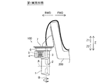
船舶推進装置100は、図1に示すように、船体200を推進させる電動推進器を含む。船舶推進装置100は、筒状のダクト1と、プロペラ部2と、ステアリングシャフト3と、ケーシング部4と、モータ制御部5と、転舵機構6とを備えている。ダクト1は、図2および図4に示すように、ステータ部11を含んでいる。プロペラ部2は、図4に示すように、リム21と、羽根22とを含んでいる。リム21は、ロータ部23を有している。図2に示すように、ステータ部11と、ロータ部23とによりモータ10(スイッチドリラクタンスモータ)を構成する。
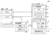
船舶推進装置100は、図1および図6に示すように、ブラケット7を介して船体200に取り付けられている。図2に示すように、船体200には、バッテリ8と、リモコン9aと、ステアリングホイール9bとが設けられている。船舶推進装置100(モータ10)は、モータ制御部5に接続されている。モータ制御部5には、バッテリ8と、リモコン9aとがさらに接続されている。モータ制御部5は、CPU(中央演算処理装置)51と、モータドライバ52と、インバータ53とを含んでいる。
船舶推進装置100(ダクト1)は、図1に示すように、プロペラ部2の回転軸線Aと交差する転舵軸線B周りに回動可能である。船舶推進装置100は、転舵機構6により、転舵(回動)される。転舵機構6は、図2に示すように、電動モータ61と、舵角センサ62とを含んでいる。転舵機構6は、ステアリングシャフト3を回動させることにより、ダクト1およびケーシング部4を転舵させる。転舵機構6は、バッテリ8と、ステアリングホイール9bとに接続されている。
船舶推進装置100は、図2に示すように、リモコン9aの操作により、推進力の大きさが調整される。船舶推進装置100は、ステアリングホイール9bの操作により、推進力の方向(ダクト1の方向)が調整される。つまり、ステアリングホイール9bが操縦されることにより、船舶推進装置100の向きが変更されて、船体200の舵が操作される。
図3および図4に示すように、ダクト1は、筒状に形成されている。ダクト1は、プロペラ部2の回転軸線A方向に沿って断面形状が変化するように形成されている。つまり、ダクト1は、X1方向が外方に広がって形成され、X2方向が徐々に狭められて形成されている。ダクト1は、内表面から径方向外方に向けて凹んた周状の凹部が形成されている。凹部には、プロペラ部2が収容されている。具体的には、プロペラ部2は、ダクト1の凹部に沿って設けられた流体軸受を介してダクト1に回転可能に支持されている。
ダクト1の凹部の外周には、ステータ部11が配置されている。ステータ部11は、巻線を含む。ステータ部11は、巻線に電力が供給されることにより、磁界が発生される。巻線は、筒状のダクト1の凹部に沿って周状に複数配置されている。複数の巻線には回転数に同期させて電力がそれぞれ供給される。これにより、プロペラ部2のロータ部23にステータ部11の磁力が作用して、プロペラ部2が回転される。
プロペラ部2は、筒状のダクト1の径方向内方に回転可能に配置されている。プロペラ部2のリム21は、羽根22の外方に筒状に設けられている。羽根22は、リム21の内表面からリム21の径方向内方に形成されている。羽根22は、図3に示すように、円周方向に沿って等間隔(90度おき)に4枚設けられている。羽根22は、翼形状を有している。
ロータ部23は、リム21の外方に設けられている。ロータ部23は、ダクト1のステータ部11と対向する位置に配置されている。具体的には、ロータ部23と、ステータ部11とは、半径方向に所定の間隔を隔てて対向している。つまり、ステータ部11およびロータ部23とにより構成されるモータ10は、ラジアルギャップ型のモータである。ロータ部23は、透磁率が大きい部分と透磁率が小さい部分とが周状に交互に配置されている。つまり、ロータ部23には、ステータ部11から発生する磁力によりリラクタンストルクが発生する。これにより、ロータ部23(リム21)が回転する。
ステアリングシャフト3は、図3および図4に示すように、ダクト1を転舵可能に支持している。具体的には、ステアリングシャフト3は、円すいころ軸受31を介して転舵機構6に回動可能に支持されている。ステアリングシャフト3は、円筒ころ軸受32を介して、ダクト1に一体的に設けられたケーシング部4を支持している。ステアリングシャフト3は、中空形状に形成されている。ステアリングシャフト3の中空形状の内部には、ステータ部11に電力を供給する配線、モータ制御部5とバッテリ8とを接続する配線、リモコン9aとモータ制御部5とを接続する配線、ステアリングホイール9bと転舵機構6とを接続する配線が収容されている。
ステアリングシャフト3には、シール33および34が設けられており、ケーシング部4内、転舵機構6内、ステータ部11への浸水が防止されている。具体的には、ステアリングシャフト3と転舵機構6との間にシール33が設けられている。ステアリングシャフト3とケーシング部4との間にシール34が設けられている。
ここで、第1実施形態では、ケーシング部4は、ステアリングシャフト3とは別個に設けられ、プロペラ部2の回転軸線A方向に沿って延びるように形成されている。ケーシング部4内には、モータ制御部5が配置されている。ケーシング部4は、ダクト1とともに転舵可能にダクト1に固定されている。具体的には、ケーシング部4は、ダクト1と一体的に設けられている。
ケーシング部4は、ダクト1の上方に配置されている。具体的には、ケーシング部4は、ダクト1と転舵機構6との間に配置されている。ケーシング部4は、少なくとも一部がステアリングシャフト3よりも後方に配置されている。ケーシング部4は、少なくとも一部がダクト1の後端よりも後方に延びるように形成されている。具体的には、ケーシング部4は、平面視においてプロペラ部2の回転軸線A方向に垂直な方向の長さよりもプロペラ部2の回転軸線A方向に平行な方向の長さの方が大きくなるように形成されている。つまり、ケーシング部4は、プロペラ部2の回転軸線A方向と平行でかつ上下方向と平行な面に沿って延びるように形成されている。ケーシング部4は、スケグとしての機能を有している。言い換えると、ケーシング部4は、船体200の航行性を安定させるフィンとしても作用する。
ケーシング部4は、図7に示すように、プロペラ部2の回転軸線A方向に沿って流線型形状に形成されている。具体的には、ケーシング部4は、X方向に相対的に流れる水に対して抵抗が小さくなるように流線型形状に形成されている。
ケーシング部4は、図7に示すように、放熱部41と、蓋部42とを含んでいる。放熱部41は、ケーシング部4のモータ制御部5が配置される近傍に、外部に露出した状態で配置されている。放熱部41は、モータ制御部5の熱を外部に放出するように設けられている。放熱部41は、アルミニウムなどの金属材料により形成されている。放熱部41の外表面には、X方向に沿って延びる複数のフィンが形成されている。これにより、表面積を大きくすることができるので、効率よく放熱することが可能である。放熱部41は、ケーシング部4の左右方向の一方に設けられている。蓋部42は、ケーシング部4の左右方向の他方に設けられている。
蓋部42は、ケーシング部4内にモータ制御部5を出し入れするために設けられている。蓋部42は、モータ制御部5を覆うように設けられている。放熱部41および蓋部42は、シールを介してケーシング部4に取り付けられている。つまり、ケーシング部4は、放熱部41および蓋部42が取り付けられた状態で、密閉されている。
モータ制御部5は、プロペラ部2(モータ10)の回転駆動を制御する。具体的には、モータ制御部5は、リモコン9aの操作に基づいて、モータ10の回転数を制御する。CPU51は、モータ10に設けられた回転数検出部10aからの信号を受信する。CPU51は、モータドライバ52およびインバータ53を介してモータ10(ステータ部11)に電力を供給する。
モータ制御部5(CPU51、モータドライバ52およびインバータ53)は、基板5a上に設けられている。基板5aは、図5に示すように、平板形状に形成されている。基板5aは、プロペラ部2の回転軸線A方向と略平行に延びるように配置されている。つまり、基板5aは、基板5aが延びる方向に沿って延びる細長形状に形成されたケーシング部4内に配置されている。基板5aは、図7に示すように、放熱部41に接触して配置されている。これにより、CPU51、モータドライバ52、インバータ53などの発熱を放熱部41に効果的に伝達することが可能である。
転舵機構6は、図3~図5に示すように、ダクト1の上方に配置され、ダクト1を転舵させるために設けられている。転舵機構6の電動モータ61は、ステアリングホイール9b(図2参照)の操作に基づいて駆動される。電動モータ61は、バッテリ8からドライバを介して電力が供給されて回転駆動される。電動モータ61は、図8に示すように、ウォームギア61aおよびギア3aを介して、ステアリングシャフト3を回動させる。電動モータ61とウォームギア61aとの間には、減速機61bが設けられている。減速機61bは、遊星ギアを有している。舵角センサ62は、ステアリングシャフト3の回動角を検知する。検知されたステアリングシャフト3の回動角がフィードバック制御されて、電動モータ61が駆動される。
転舵機構6は、外表面が前後進方向に沿って流線型形状に形成されている。図1および図6に示すように、転舵機構6の上面(Z1方向の面)は、船体200に取り付けられるブラケット7に固定されている。
ブラケット7は、図6に示すように、船舶推進装置100を支持するとともに、船体200の後方に取り付けられている。ブラケット7は、船体取付部71と、推進装置取付部72とを含んでいる。船体取付部71は、平板状に形成されている。船体取付部71は、船体200の後方のトランサムに取り付けられている。推進装置取付部72は、船体取付部71に所定の角度を有して取り付けられている。推進装置取付部72は、略水平方向の平板状に形成されている。推進装置取付部72には、船舶推進装置100が取り付けられている。推進装置取付部72には、船舶推進装置100を複数取り付けることが可能である。具体的には、推進装置取付部72は、船舶推進装置100を取り付けるための孔部711(ボルトの挿通孔)が複数設けられている。船体取付部71は、エンジンを備える船外機を取り付けるためのブラケットに対応して、複数の孔部711が設けられている。船体取付部71の孔部711は、たとえば、船外機のブラケットと同様に、左右方向に約12.8インチ(約327mm)の間隔を隔て列状に配置されている。これにより、船外機の代わりに船体200に船舶推進装置100を容易に取り付けることが可能である。
上記第1実施形態では、以下のような効果を得ることができる。
第1実施形態では、上記のように、ステアリングシャフト3とは別個に設けられ、プロペラ部2の回転軸線A方向に沿って延びるように形成されたケーシング部4内に、プロペラ部2の回転駆動を制御するモータ制御部5を配置する。これにより、モータ制御部5とモータ10とを近くに配置することができるので、接続する配線が長くなるのを抑制することができる。その結果、配線が煩雑になるのを抑制することができる。モータ制御部5を大きくした場合でも、ケーシング部4をプロペラ部2の回転軸線A方向に沿って大きくすることにより、ケーシング部4内にモータ制御部5を収容することができるので、ステアリングシャフト3の径を大きくする場合と異なり、装置が過度に大型化するのを抑制することができる。これらにより、配線が煩雑になるのを抑制しながら、装置が大型化するのを抑制することが可能な船舶推進装置100を提供することができる。ケーシング部4をプロペラ部2の回転軸線A方向に沿って延びるように形成することにより、水の抵抗が大きくなるのを抑制することができるので、ケーシング部4を設けたとしても、支障なく船舶を推進させることができる。ケーシング部4を水中に配置することができるので、ケーシング部4内に配置されたモータ制御部5を効率よく冷却させることができる。
第1実施形態では、上記のように、ケーシング部4を、ダクト1とともに転舵可能にダクト1に固定する。これにより、ダクト1とケーシング部4とが一体的に転舵されるので、ダクト1を転舵した場合でも、ケーシング部4に起因して水の抵抗が大きくなるのを抑制することができる。
第1実施形態では、上記のように、ケーシング部4を、ダクト1と一体的に設ける。これにより、ダクト1とケーシング部4とを別体で設ける場合に比べて、部品点数を減少させることができるとともに、ダクト1とケーシング部4との接合面をなくすことができるので、浸水を効果的に抑制することができる。
第1実施形態では、上記のように、ケーシング部4を、ダクト1の上方に配置する。これにより、水面からの空気の巻き込みを抑制するために、ダクト1を水面から下方に離して配置する場合に、ダクト1と水面との間のスペースを有効に活用して、ケーシング部4を配置することができる。
第1実施形態では、上記のように、ケーシング部4を、少なくとも一部がステアリングシャフト3よりも後方になるように配置する。これにより、ケーシング部4をステアリングシャフト3よりも後方に延ばすことができるので、ダクト1とともにケーシング部4を転舵させた場合に、船舶推進装置100が取り付けられる船体200にケーシング部4が干渉するのを抑制することができる。
第1実施形態では、上記のように、ケーシング部4を、少なくとも一部がダクト1の後端よりも後方に延びるように形成する。これにより、モータ制御部5が大きくなった場合でも、ケーシング部4をダクト1の後端よりも後方に延びるようにして大きくすることができるので、モータ制御部5をケーシング部4に容易に収容することができる。
第1実施形態では、上記のように、ケーシング部4が、スケグとしての機能を有する。これにより、モータ制御部5が配置されたケーシング部4を用いて船舶の操舵性を向上させることができる。
第1実施形態では、上記のように、ケーシング部4を、平面視においてプロペラ部2の回転軸線A方向に垂直な方向の長さよりもプロペラ部2の回転軸線A方向に平行な方向の長さの方が大きくなるように形成する。これにより、ケーシング部4をプロペラ部2の回転軸線A方向に見た場合の投影面積が大きくなるのを抑制することができるので、水の抵抗が大きくなるのを効果的に抑制することができる。
第1実施形態では、上記のように、ケーシング部4のモータ制御部5が配置される近傍に、外部に露出した放熱部41を設ける。これにより、モータ制御部5の熱を放熱部41を介して容易に外部(水中)に放出することができるので、モータ制御部5を効果的に冷却することができる。
第1実施形態では、上記のように、モータ制御部5を、プロペラ部2の回転軸線A方向と略平行に延びるように配置された基板5a上に設け、ケーシング部4を、基板5aが延びる方向に沿って延びる細長形状に形成する。これにより、モータ制御部5が設けられた基板5aを細長形状のケーシング部4に容易に収容することができる。
第1実施形態では、上記のように、ケーシング部4を、プロペラ部2の回転軸線A方向に沿って流線型形状に形成する。これにより、ケーシング部4の水の抵抗を効果的に小さくすることができるので、ケーシング部4を設けたとしても、効率よく船舶を推進させることができる。
第1実施形態では、上記のように、モータ制御部5は、モータドライバ52およびインバータ53を含む。これにより、モータドライバ52およびインバータ53を、水中に配置されるケーシング部4内に収容することができるので、モータドライバ52およびインバータ53を効果的に冷却することができる。
第1実施形態では、上記のように、ダクト1を、プロペラ部2の回転軸線A方向に沿って断面形状が変化するように形成する。これにより、ダクト1内を流れる流体を整流することができるので、効率よく推進力を発生させることができる。
第1実施形態では、上記のように、羽根22を、3枚以上8枚以下設ける。これにより、リム21の径方向内方に3枚以上8枚以下の羽根22をバランスよく配置することができるので、船舶推進装置100を効率よく動作させることができる。
第1実施形態では、上記のように、ダクト1の上方に配置され、ダクト1を転舵させる転舵機構6を設け、ケーシング部4を、ダクト1と転舵機構6との間に配置する。これにより、転舵機構6によりダクト1を容易に転舵させることができる。水面からの空気の巻き込みを抑制するために、ダクト1を水面から下方に離して配置する場合に、ダクト1と転舵機構6との間のスペースを有効に活用して、ケーシング部4を配置することができる。
第1実施形態では、上記のように、転舵機構6を、前後進方向に沿って流線型形状に形成する。これにより、転舵機構6の水の抵抗を効果的に小さくすることができるので、より効率よく船舶を推進させることができる。
第1実施形態では、上記のように、転舵機構6を、電動モータ61の駆動によりステアリングシャフト3を回動させるようにする。これにより、電動モータ61を駆動させることにより、容易にダクト1を転舵させることができる。
第1実施形態では、上記のように、転舵機構6の上面を、船体200に取り付けられるブラケット7に固定する。これにより、転舵機構6を船体200に確実に取り付けることができる。
第1実施形態では、上記のように、ブラケット7は、船体取付部71と、推進装置取付部72とを含む。これにより、船体取付部71を船体200に固定することができるとともに、推進装置取付部72に船舶推進装置100を固定することができるので、船舶推進装置100を確実に船体200に取り付けることができる。
(第2実施形態)
次に、図9を参照して、本発明の第2実施形態について説明する。この第2実施形態では、ケーシング部がダクトの上方に配置されていた上記第1実施形態とは異なり、ケーシング部がダクトの後方に配置されている例について説明する。なお、第1実施形態と同様の箇所には同様の符号を付している。
次に、図9を参照して、本発明の第2実施形態について説明する。この第2実施形態では、ケーシング部がダクトの上方に配置されていた上記第1実施形態とは異なり、ケーシング部がダクトの後方に配置されている例について説明する。なお、第1実施形態と同様の箇所には同様の符号を付している。
船舶推進装置300は、筒状のダクト1と、プロペラ部2と、ステアリングシャフト3と、ケーシング部4aと、モータ制御部5と、転舵機構6とを備えている。
ここで、第2実施形態では、ケーシング部4aは、ステアリングシャフト3とは別個に設けられ、プロペラ部2の回転軸線A方向に沿って延びるように形成されている。ケーシング部4a内には、モータ制御部5が配置されている。ケーシング部4aは、少なくとも一部がダクト1の後端よりも後方に延びるように形成されている。ケーシング部4aは、プロペラ部2の回転軸線A上におけるダクト1の後方においてダクト1に固定されている。具体的には、ケーシング部4aは、ダクト1の後方において、上下方向(Z方向)に延びるように形成されている。
なお、第2実施形態のその他の構成は、上記第1実施形態と同様である。
第2実施形態では、以下のような効果を得ることができる。
第2実施形態では、上記第1実施形態と同様に、ステアリングシャフト3とは別個に設けられ、プロペラ部2の回転軸線A方向に沿って延びるように形成されたケーシング部4a内に、プロペラ部2の回転駆動を制御するモータ制御部5を配置する。これにより、配線が煩雑になるのを抑制しながら、装置が大型化するのを抑制することができる。
第2実施形態では、上記のように、ケーシング部4aを、プロペラ部2の回転軸線A上におけるダクト1の後方においてダクト1に固定する。これにより、ダクト1から吐出される水流をケーシング部4aにより整流することができるので、より効率よく船舶を推進させることができる。
なお、第2実施形態のその他の効果は、上記第1実施形態と同様である。
(第3実施形態)
次に、図10~図13を参照して、本発明の第3実施形態について説明する。この第3実施形態では、ステアリングシャフトを囲むように配置されたダクト接続部にカラーを設けた例について説明する。なお、第1実施形態と同様の箇所には同様の符号を付している。
次に、図10~図13を参照して、本発明の第3実施形態について説明する。この第3実施形態では、ステアリングシャフトを囲むように配置されたダクト接続部にカラーを設けた例について説明する。なお、第1実施形態と同様の箇所には同様の符号を付している。
船舶推進装置400は、図10に示すように、筒状のダクト1と、プロペラ部2(図11参照)と、ステアリングシャフト3と、ケーシング部4bと、モータ制御部5と、転舵機構6とを備えている。
ここで、第3実施形態では、図10に示すように、船体200に設けられたリモコン9aは、CPU91を含んでいる。CPU91は、モータ制御部5に接続されている。CPU91は、モータ制御部5を介して、プロペラ部2(モータ10)の回転駆動を制御する。具体的には、CPU91は、リモコン9aの操作に基づいて、モータ10の回転数を制御する。CPU91は、モータ10に設けられた回転数検出部10aからの信号を受信する。CPU91は、モータ制御部5(モータドライバ52およびインバータ53)を介してモータ10(ステータ部11)に電力を供給する。
CPU91は、ステアリングホイール9bの操作に基づいて、転舵機構6を制御する。CPU91は、モータ制御部5を介して転舵機構6に電力を供給する。つまり、CPU91は、ステアリングホイール9bの操作に基づいて、モータ制御部5を介して転舵機構6により、ダクト1を転舵させる制御を行う。これにより、船体200に設けられたCPU91により、集中して操船操作を制御することが可能である。
ここで、第3実施形態では、ケーシング部4bは、ステアリングシャフト3とは別個に設けられ、プロペラ部2の回転軸線A方向(図1参照)に沿って延びるように形成されている。ケーシング部4b内には、モータ制御部5が配置されている。ケーシング部4bは、ダクト1とともに転舵可能にダクト1に固定されている。具体的には、図11に示すように、ケーシング部4bは、ダクト1の上方に接続され、ステアリングシャフト3を囲むように配置されたダクト接続部43に取り付けられるように構成されている。詳しくは、ケーシング部4bは、ダクト接続部43の後方に着脱可能に取り付けられるように構成されている。
ダクト1は、図11および図12に示すように、中央部12と、前方部13と、後方部14とに分割可能に構成されている。中央部12には、ステータ部11(図10参照)が配置されている。中央部12は、ダクト接続部43の下方に接続されている。中央部12とダクト接続部43とは、一体的に形成されている。
中央部12と、前方部13と、後方部14とが分離された状態で、中央部12にプロペラ部2が取り付けられるように構成されている。前方部13は、中央部12の前方に接続されている。前方部13は、中央部12の内周に設けられたネジ部と、前方部13の外周に設けられたネジ部とが係合することにより、中央部12に固定される。後方部14は、中央部12の後方に接続されている。後方部14は、中央部12の内周に設けられたネジ部と、後方部14の外周に設けられたネジ部とが係合することにより、中央部12に固定される。
ダクト接続部43は、図11に示すように、ダクト1の上方に接続されている。ダクト接続部43は、ステアリングシャフト3を囲むように配置されている。ダクト接続部43は、筐体部431と、カラー432と、貫通孔433とを含んでいる。筐体部431は、図13に示すように、内部空間43aを有している。ステアリングシャフト3は、筐体部431の内部空間43aに配置されている。具体的には、筐体部431の内部空間43aには、転舵機構6の筐体の下部と、転舵機構6の筐体の内部に配置されたステアリングシャフト3とが配置されている。
ここで、第3実施形態では、カラー432は、筐体部431の上端の筐体部431とステアリングシャフト3との間の内部空間43aに配置されている。カラー432は、ダクト接続部43の内部空間43aに通じる開口面積を小さくするために設けられている。カラー432は、筐体部431と、転舵機構6の筐体との間に配置されている。カラー432は、円環状に形成されている。カラー432は、樹脂により形成されている。カラー432は、外周部が筐体部431に接するように圧入されている。カラー432の内周または外周の隙間の径方向の長さd2は、貫通孔433の内径d1よりも小さくなるように構成されている。
貫通孔433は、ステアリングシャフト3が配置された内部空間43aと外部とを連通するように構成されている。貫通孔433は、カラー432よりも下方(Z2方向)に設けられている。貫通孔433は、ダクト接続部43の左方に1つ、右方に1つの計2つ設けられている。貫通孔433は、筐体部431の内部空間43aの下端近傍に設けられている。
なお、第3実施形態のその他の構成は、上記第1実施形態と同様である。
第3実施形態では、以下のような効果を得ることができる。
第3実施形態では、上記第1実施形態と同様に、ステアリングシャフト3とは別個に設けられ、プロペラ部2の回転軸線A方向に沿って延びるように形成されたケーシング部4b内に、プロペラ部2の回転駆動を制御するモータ制御部5を配置する。これにより、配線が煩雑になるのを抑制しながら、装置が大型化するのを抑制することができる。
第3実施形態では、上記のように、ダクト接続部43は、ステアリングシャフト3が内部空間43aに配置された筐体部431と、筐体部431の上端の筐体部431とステアリングシャフト3との間の内部空間43aに配置されたカラー432と、ステアリングシャフト3が配置された内部空間43aと外部とを連通するとともに、カラー432よりも下方に設けられた貫通孔433とを含む。これにより、ダクト接続部43に上面から異物が侵入するのをカラー432により抑制することができる。ダクト接続部43に異物が侵入した場合でも、下方に設けられた貫通孔433から排出することができる。これらにより、ダクト接続部43に異物が堆積するのを抑制することができる。
第3実施形態では、上記のように、カラー432の内周または外周の隙間の径方向の長さd2を、貫通孔433の内径d1よりも小さくなるように構成する。これにより、カラー432の内周または外周の隙間から異物が侵入した場合でも、隙間より大きい内径を有する貫通孔433から容易に排出することができる。
なお、第3実施形態のその他の効果は、上記第1実施形態と同様である。
今回開示された実施形態は、すべての点で例示であって制限的なものではないと考えられるべきである。本発明の範囲は、上記した実施形態の説明ではなく特許請求の範囲によって示され、さらに特許請求の範囲と均等の意味および範囲内でのすべての変更(変形例)が含まれる。
たとえば、上記第1~第3実施形態では、船舶推進装置が船体に1つ設けられている構成の例を示したが、本発明はこれに限られない。本発明では、船体に複数の船舶推進装置が設けられていてもよい。たとえば、図10に示す変形例のように、船体200に、2つの船舶推進装置100が設けられていてもよい。
上記第1~第3実施形態では、ケーシング部が上下方向および前後方向に延びる細長形状に形成されている例を示したが、本発明はこれに限られない。本発明では、ケーシング部が左右方向および前後方向(水平方向)に延びる細長形状に形成されていてもよい。この場合、ケーシング部が、プロペラ部の駆動時の空気の巻き込みを抑制するキャビテーションプレートとして機能してもよい。
上記第1および第2実施形態では、モータ制御部が、CPU、モータドライバおよびインバータを含む例を示したが、本発明はこれに限られない。本発明では、モータ制御部が、モータドライバおよびインバータの少なくとも一方を含んでいればよい。
上記第1~第3実施形態では、ダクトを転舵機構によりで転舵させる例を示したが、本発明はこれに限られない。本発明では、ティラーハンドルなどを設けて、ダクト(船舶推進装置)を手動で転舵させてもよい。
上記第1~第3実施形態では、転舵機構が電動により駆動される例を示したが、本発明はこれに限られない。本発明では、転舵機構を油圧により駆動させてもよい。
上記第1~第3実施形態では、ステアリングホイールおよびリモコンの操作に基づいて、船舶推進装置を操縦する例を示したが、本発明はこれに限られない。本発明では、ジョイスティックなどの操作に基づいて、船舶推進装置を操縦してもよい。
上記第1~第3実施形態では、プロペラ部に4枚の羽根を設ける例を示したが、本発明はこれに限られない。本発明では、羽根は、3枚以下であってもよいし、5枚以上であってもよい。
上記第1~第3実施形態では、プロペラ部の回転軸線上にシャフトを設けていない例を示したが、本発明はこれに限られない。本発明では、プロペラ部の回転軸線上に羽根に接続されたシャフトを設けてもよい。
上記第1~第3実施形態では、ステータ部とロータ部とにより構成されるモータがラジアルギャップ型のモータである例を示したが、本発明はこれに限られない。本発明では、ステータ部とロータ部とが回転軸線方向において対向するように配置されるアキシャルギャップ型のモータとしてもよい。
上記第1~第3実施形態では、ステータ部とロータ部とにより構成されるモータがリラクタンストルク式のモータである例を示したが、本発明はこれに限られない。本発明では、ロータ部に複数の永久磁石を設けた永久磁石式のモータとしてもよい。
上記第1~第3実施形態では、船体の後方に船舶推進装置が取り付けられている例を示したが、本発明はこれに限られない。本発明の船舶推進装置を船体の前方または側方に取り付けて用いてもよい。
1 ダクト
2 プロペラ部
3 ステアリングシャフト
4、4a ケーシング部
5 モータ制御部
5a 基板
6 転舵機構
7 ブラケット
11 ステータ部
21 リム
22 羽根
23 ロータ部
41 放熱部
43 ダクト接続部
43a 内部空間
61 電動モータ
71 船体取付部
72 推進装置取付部
100、300、400 船舶推進装置
200 船体
431 筐体部
432 カラー
433 貫通孔
2 プロペラ部
3 ステアリングシャフト
4、4a ケーシング部
5 モータ制御部
5a 基板
6 転舵機構
7 ブラケット
11 ステータ部
21 リム
22 羽根
23 ロータ部
41 放熱部
43 ダクト接続部
43a 内部空間
61 電動モータ
71 船体取付部
72 推進装置取付部
100、300、400 船舶推進装置
200 船体
431 筐体部
432 カラー
433 貫通孔
Claims (22)
- ステータ部を含むダクトと、
前記ステータ部と対向する位置に配置されるロータ部を有するリムと、前記リムの径方向内方に形成された羽根とを含むプロペラ部と、
前記ダクトを転舵可能に支持するステアリングシャフトと、
前記ステアリングシャフトとは別個に設けられ、前記プロペラ部の回転軸線方向に沿って延びるように形成されたケーシング部と、
前記ケーシング部内に配置され、前記プロペラ部の回転駆動を制御するモータ制御部とを備える、船舶推進装置。 - 前記ケーシング部は、前記ダクトとともに転舵可能に前記ダクトに固定されている、請求項1に記載の船舶推進装置。
- 前記ケーシング部は、前記ダクトと一体的に設けられている、請求項2に記載の船舶推進装置。
- 前記ケーシング部は、前記ダクトの上方に配置されている、請求項1~3のいずれか1項に記載の船舶推進装置。
- 前記ケーシング部は、少なくとも一部が前記ステアリングシャフトよりも後方に配置されている、請求項1~4のいずれか1項に記載の船舶推進装置。
- 前記ケーシング部は、少なくとも一部が前記ダクトの後端よりも後方に延びるように形成されている、請求項1~5のいずれか1項に記載の船舶推進装置。
- 前記ケーシング部は、前記プロペラ部の回転軸線上における前記ダクトの後方において前記ダクトに固定されている、請求項6に記載の船舶推進装置。
- 前記ケーシング部は、スケグとしての機能を有する、請求項1~7のいずれか1項に記載の船舶推進装置。
- 前記ケーシング部は、平面視において前記プロペラ部の回転軸線方向に垂直な方向の長さよりも前記プロペラ部の回転軸線方向に平行な方向の長さの方が大きくなるように形成されている、請求項1~8のいずれか1項に記載の船舶推進装置。
- 前記ケーシング部の前記モータ制御部が配置される近傍には、外部に露出した放熱部が設けられている、請求項1~9のいずれか1項に記載の船舶推進装置。
- 前記モータ制御部は、前記プロペラ部の回転軸線方向と略平行に延びるように配置された基板上に設けらており、
前記ケーシング部は、前記基板が延びる方向に沿って延びる細長形状に形成されている、請求項1~10のいずれか1項に記載の船舶推進装置。 - 前記ケーシング部は、前記プロペラ部の回転軸線方向に沿って流線型形状に形成されている、請求項1~11のいずれか1項に記載の船舶推進装置。
- 前記モータ制御部は、モータドライバおよびインバータのうち少なくとも一方を含む、請求項1~12のいずれか1項に記載の船舶推進装置。
- 前記ダクトは、前記プロペラ部の回転軸線方向に沿って断面形状が変化するように形成されている、請求項1~13のいずれか1項に記載の船舶推進装置。
- 前記羽根は、3枚以上8枚以下設けられている、請求項1~14のいずれか1項に記載の船舶推進装置。
- 前記ダクトの上方に配置され、前記ダクトを転舵させる転舵機構をさらに備え、
前記ケーシング部は、前記ダクトと前記転舵機構との間に配置されている、請求項1~15のいずれか1項に記載の船舶推進装置。 - 前記転舵機構は、前後進方向に沿って流線型形状に形成されている、請求項16に記載の船舶推進装置。
- 前記転舵機構は、電動モータを含み、前記電動モータの駆動により前記ステアリングシャフトを回動させるように構成されている、請求項16または17に記載の船舶推進装置。
- 前記転舵機構の上面は、船体に取り付けられるブラケットに固定されている、請求項16~18のいずれか1項に記載の船舶推進装置。
- 前記ブラケットは、船体取付部と、推進装置取付部とを含む、請求項19に記載の船舶推進装置。
- 前記ダクトの上方に接続され、前記ステアリングシャフトを囲むように配置されたダクト接続部をさらに備え、
前記ダクト接続部は、前記ステアリングシャフトが内部空間に配置された筐体部と、前記筐体部の上端の前記筐体部と前記ステアリングシャフトとの間の前記内部空間に配置されたカラーと、前記ステアリングシャフトが配置された前記内部空間と外部とを連通するとともに、前記カラーよりも下方に設けられた貫通孔とを含んでいる、請求項1~20のいずれか1項に記載の船舶推進装置。 - 前記カラーの内周または外周の隙間の径方向の長さは、前記貫通孔の内径よりも小さい、請求項21に記載の船舶推進装置。
Priority Applications (4)
| Application Number | Priority Date | Filing Date | Title |
|---|---|---|---|
| JP2017550333A JP6783243B2 (ja) | 2015-11-11 | 2016-11-08 | 船舶推進装置 |
| EP20160973.2A EP3705393B1 (en) | 2015-11-11 | 2016-11-08 | Marine propulsion unit |
| EP16864209.8A EP3375705B1 (en) | 2015-11-11 | 2016-11-08 | Ship propulsion device |
| US15/975,812 US10618617B2 (en) | 2005-11-11 | 2018-05-10 | Marine propulsion unit |
Applications Claiming Priority (2)
| Application Number | Priority Date | Filing Date | Title |
|---|---|---|---|
| JP2015-221550 | 2015-11-11 | ||
| JP2015221550 | 2015-11-11 |
Related Child Applications (1)
| Application Number | Title | Priority Date | Filing Date |
|---|---|---|---|
| US15/975,812 Continuation US10618617B2 (en) | 2005-11-11 | 2018-05-10 | Marine propulsion unit |
Publications (1)
| Publication Number | Publication Date |
|---|---|
| WO2017082248A1 true WO2017082248A1 (ja) | 2017-05-18 |
Family
ID=58695391
Family Applications (1)
| Application Number | Title | Priority Date | Filing Date |
|---|---|---|---|
| PCT/JP2016/083102 Ceased WO2017082248A1 (ja) | 2005-11-11 | 2016-11-08 | 船舶推進装置 |
Country Status (4)
| Country | Link |
|---|---|
| US (1) | US10618617B2 (ja) |
| EP (2) | EP3705393B1 (ja) |
| JP (1) | JP6783243B2 (ja) |
| WO (1) | WO2017082248A1 (ja) |
Cited By (9)
| Publication number | Priority date | Publication date | Assignee | Title |
|---|---|---|---|---|
| CN111699131A (zh) * | 2017-11-28 | 2020-09-22 | 斐特宝得有限公司 | 用于将桅杆连接到板的模块 |
| EP3842332A1 (en) | 2019-12-26 | 2021-06-30 | Yamaha Hatsudoki Kabushiki Kaisha | Marine propulsion unit |
| EP3842333A1 (en) | 2019-12-26 | 2021-06-30 | Yamaha Hatsudoki Kabushiki Kaisha | Marine propulsion unit |
| EP3971081A1 (en) | 2020-09-15 | 2022-03-23 | Yamaha Hatsudoki Kabushiki Kaisha | Marine vessel maneuvering system and control method of marine vessel |
| JP2023044490A (ja) * | 2021-09-17 | 2023-03-30 | スズキ株式会社 | ハイブリッド船舶推進機 |
| WO2023187887A1 (ja) * | 2022-03-28 | 2023-10-05 | 本田技研工業株式会社 | 電動船外機および船舶 |
| US20240190546A1 (en) * | 2022-12-09 | 2024-06-13 | Yamaha Hatsudoki Kabushiki Kaisha | Marine propulsion device and marine vessel |
| JP7534002B1 (ja) | 2022-07-21 | 2024-08-14 | 江蘇科技大学 | スリップリングレス電気式ポッド推進装置及びその組立方法 |
| JP2025141491A (ja) * | 2024-03-15 | 2025-09-29 | 本田技研工業株式会社 | 水上移動体用推進装置 |
Families Citing this family (16)
| Publication number | Priority date | Publication date | Assignee | Title |
|---|---|---|---|---|
| CN110395377A (zh) * | 2019-08-02 | 2019-11-01 | 武汉札古海洋科技有限公司 | 一种水下推进器 |
| CN110963014A (zh) * | 2019-12-30 | 2020-04-07 | 宁波海伯集团有限公司 | 一种小型船用推进器 |
| JP2022018647A (ja) * | 2020-07-16 | 2022-01-27 | ヤマハ発動機株式会社 | 船外機 |
| SI26066A (sl) * | 2020-08-28 | 2022-03-31 | Remigo, Proizvodnja In Trgovina, D.O.O. | Integriran električni izvenkrmni motor |
| WO2023034027A1 (en) * | 2021-09-05 | 2023-03-09 | Muller Peter Jacques | Rim driven thruster with adjustable rotor blade pitch |
| CN113650771A (zh) * | 2021-09-18 | 2021-11-16 | 国网智慧能源交通技术创新中心(苏州)有限公司 | 一种基于集成转舵系统的轮缘推进系统 |
| CN113815832B (zh) * | 2021-09-19 | 2023-05-02 | 苏州汉瑞船舶推进系统有限公司 | 轮缘驱动的半浸式推进器 |
| CN114455053B (zh) * | 2022-01-22 | 2023-03-07 | 嘉兴市锦佳船舶制造股份有限公司 | 一种河湖巡查船 |
| US12065230B1 (en) | 2022-02-15 | 2024-08-20 | Brunswick Corporation | Marine propulsion control system and method with rear and lateral marine drives |
| US12304330B1 (en) | 2022-02-16 | 2025-05-20 | Charles B. Hickcox, III | Electric outboard motor |
| CN115092374B (zh) * | 2022-06-28 | 2024-01-19 | 北京航空航天大学 | 一种泵喷式水下矢量推进器 |
| KR20240009887A (ko) * | 2022-07-14 | 2024-01-23 | 얀마 홀딩스 주식회사 | 전동 세일 드라이브 및 선박 |
| US12134454B1 (en) | 2022-07-20 | 2024-11-05 | Brunswick Corporation | Marine propulsion system and method with single rear drive and lateral marine drive |
| US12258115B2 (en) | 2022-07-20 | 2025-03-25 | Brunswick Corporation | Marine propulsion system and joystick control method |
| US12110088B1 (en) | 2022-07-20 | 2024-10-08 | Brunswick Corporation | Marine propulsion system and method with rear and lateral marine drives |
| CN116729607A (zh) * | 2023-05-31 | 2023-09-12 | 大连海事大学 | 一种桨舵一体的吊舱对转轮缘推进器 |
Citations (3)
| Publication number | Priority date | Publication date | Assignee | Title |
|---|---|---|---|---|
| JPH09164998A (ja) * | 1995-12-14 | 1997-06-24 | Moriyama Kogyo Kk | 電動船外機の制御装置 |
| JP2006056458A (ja) * | 2004-08-23 | 2006-03-02 | Yamaha Marine Co Ltd | 電動推進機 |
| JP2013100013A (ja) * | 2011-11-08 | 2013-05-23 | Yamaha Motor Co Ltd | 船舶推進装置 |
Family Cites Families (4)
| Publication number | Priority date | Publication date | Assignee | Title |
|---|---|---|---|---|
| US5306183A (en) * | 1993-02-25 | 1994-04-26 | Harbor Branch Oceanographic Institute Inc. | Propulsion systems for submarine vessels |
| US6692319B2 (en) * | 2002-03-29 | 2004-02-17 | Alstom Shilling Robotics | Thruster for submarine vessels |
| JP5844617B2 (ja) * | 2011-11-08 | 2016-01-20 | ヤマハ発動機株式会社 | 船舶推進装置 |
| ITTO20130045A1 (it) * | 2013-01-18 | 2014-07-19 | P Gevs Srl | Sistema di propulsione fuoribordo per natanti |
-
2016
- 2016-11-08 WO PCT/JP2016/083102 patent/WO2017082248A1/ja not_active Ceased
- 2016-11-08 EP EP20160973.2A patent/EP3705393B1/en active Active
- 2016-11-08 JP JP2017550333A patent/JP6783243B2/ja active Active
- 2016-11-08 EP EP16864209.8A patent/EP3375705B1/en active Active
-
2018
- 2018-05-10 US US15/975,812 patent/US10618617B2/en active Active
Patent Citations (3)
| Publication number | Priority date | Publication date | Assignee | Title |
|---|---|---|---|---|
| JPH09164998A (ja) * | 1995-12-14 | 1997-06-24 | Moriyama Kogyo Kk | 電動船外機の制御装置 |
| JP2006056458A (ja) * | 2004-08-23 | 2006-03-02 | Yamaha Marine Co Ltd | 電動推進機 |
| JP2013100013A (ja) * | 2011-11-08 | 2013-05-23 | Yamaha Motor Co Ltd | 船舶推進装置 |
Cited By (17)
| Publication number | Priority date | Publication date | Assignee | Title |
|---|---|---|---|---|
| JP7268050B2 (ja) | 2017-11-28 | 2023-05-02 | フライトボード プロプライエタリー リミテッド | マストをボードに接続するためのモジュール |
| JP2021504243A (ja) * | 2017-11-28 | 2021-02-15 | フライトボード プロプライエタリー リミテッド | マストをボードに接続するためのモジュール |
| CN111699131A (zh) * | 2017-11-28 | 2020-09-22 | 斐特宝得有限公司 | 用于将桅杆连接到板的模块 |
| EP3842332A1 (en) | 2019-12-26 | 2021-06-30 | Yamaha Hatsudoki Kabushiki Kaisha | Marine propulsion unit |
| EP3842333A1 (en) | 2019-12-26 | 2021-06-30 | Yamaha Hatsudoki Kabushiki Kaisha | Marine propulsion unit |
| US11465720B2 (en) | 2019-12-26 | 2022-10-11 | Yamaha Hatsudoki Kabushiki Kaisha | Marine propulsion unit and marine vessel |
| US11465725B2 (en) | 2019-12-26 | 2022-10-11 | Yamaha Hatsudoki Kabushiki Kaisha | Marine propulsion unit and marine vessel |
| EP3971081A1 (en) | 2020-09-15 | 2022-03-23 | Yamaha Hatsudoki Kabushiki Kaisha | Marine vessel maneuvering system and control method of marine vessel |
| US11987338B2 (en) | 2020-09-15 | 2024-05-21 | Yamaha Hatsudoki Kabushiki Kaisha | Marine vessel maneuvering system and marine vessel |
| JP2023044490A (ja) * | 2021-09-17 | 2023-03-30 | スズキ株式会社 | ハイブリッド船舶推進機 |
| US12358602B2 (en) | 2021-09-17 | 2025-07-15 | Suzuki Motor Corporation | Hybrid ship propulsion machine |
| JP7753745B2 (ja) | 2021-09-17 | 2025-10-15 | スズキ株式会社 | ハイブリッド船舶推進機 |
| WO2023187887A1 (ja) * | 2022-03-28 | 2023-10-05 | 本田技研工業株式会社 | 電動船外機および船舶 |
| JP7534002B1 (ja) | 2022-07-21 | 2024-08-14 | 江蘇科技大学 | スリップリングレス電気式ポッド推進装置及びその組立方法 |
| JP2024531011A (ja) * | 2022-07-21 | 2024-08-29 | 江蘇科技大学 | スリップリングレス電気式ポッド推進装置及びその組立方法 |
| US20240190546A1 (en) * | 2022-12-09 | 2024-06-13 | Yamaha Hatsudoki Kabushiki Kaisha | Marine propulsion device and marine vessel |
| JP2025141491A (ja) * | 2024-03-15 | 2025-09-29 | 本田技研工業株式会社 | 水上移動体用推進装置 |
Also Published As
| Publication number | Publication date |
|---|---|
| JP6783243B2 (ja) | 2020-11-11 |
| JPWO2017082248A1 (ja) | 2018-08-30 |
| US10618617B2 (en) | 2020-04-14 |
| EP3705393B1 (en) | 2022-04-27 |
| EP3375705B1 (en) | 2020-04-15 |
| EP3375705A1 (en) | 2018-09-19 |
| EP3375705A4 (en) | 2018-10-24 |
| US20180257750A1 (en) | 2018-09-13 |
| EP3705393A1 (en) | 2020-09-09 |
Similar Documents
| Publication | Publication Date | Title |
|---|---|---|
| JP6783243B2 (ja) | 船舶推進装置 | |
| EP3141472B1 (en) | Podded all-direction pump-jet vector propeller | |
| EP1466826B1 (en) | Propulsion unit of marine vessel | |
| CN102256868B (zh) | 用于船舶的横向推进器 | |
| EP3000718B1 (en) | Electrical propulsion device | |
| JP7263417B2 (ja) | 船外機 | |
| JP4789953B2 (ja) | 船舶用推進システム | |
| JP2003011889A (ja) | アジマス推進器 | |
| JP2018079742A (ja) | 船舶用推進装置およびそれを備えた船舶 | |
| JP5384787B2 (ja) | 水上船舶用の推進システム | |
| JP2013522119A (ja) | 船舶用推進装置及びこれを備えた船舶 | |
| KR20130000961A (ko) | 포드형 추진기 및 이를 구비하는 선박 | |
| JP2011088540A (ja) | 水中翼を設けた船舶 | |
| KR101701749B1 (ko) | 선박 추진장치 | |
| CN111392011A (zh) | 共轴推进器动力系统及共轴双桨水下推进器和飞行器 | |
| KR101159205B1 (ko) | 선박용 방향타 및 이를 포함하는 선박 | |
| EP3939878B1 (en) | Outboard motor | |
| US20170334537A1 (en) | Outboard motor | |
| EP4304927A1 (en) | A propulsion assembly for a marine vessel | |
| JP4713631B2 (ja) | 船外機 | |
| KR20180076925A (ko) | 스러스터 장착형 러더 | |
| KR20150002615U (ko) | 고정식 러더벌브를 구비한 전가동타 | |
| JP4709686B2 (ja) | 船外機 | |
| WO2005058690A1 (en) | Support for propulsion apparatus for a water-borne vessel, and propulsion apparatus incorporating such support | |
| KR101334333B1 (ko) | 선박 |
Legal Events
| Date | Code | Title | Description |
|---|---|---|---|
| 121 | Ep: the epo has been informed by wipo that ep was designated in this application |
Ref document number: 16864209 Country of ref document: EP Kind code of ref document: A1 |
|
| ENP | Entry into the national phase |
Ref document number: 2017550333 Country of ref document: JP Kind code of ref document: A |
|
| NENP | Non-entry into the national phase |
Ref country code: DE |
|
| WWE | Wipo information: entry into national phase |
Ref document number: 2016864209 Country of ref document: EP |