WO2017082324A1 - 異常診断装置 - Google Patents
異常診断装置 Download PDFInfo
- Publication number
- WO2017082324A1 WO2017082324A1 PCT/JP2016/083305 JP2016083305W WO2017082324A1 WO 2017082324 A1 WO2017082324 A1 WO 2017082324A1 JP 2016083305 W JP2016083305 W JP 2016083305W WO 2017082324 A1 WO2017082324 A1 WO 2017082324A1
- Authority
- WO
- WIPO (PCT)
- Prior art keywords
- heat flux
- sensor
- heat
- flux sensor
- target device
- Prior art date
- Legal status (The legal status is an assumption and is not a legal conclusion. Google has not performed a legal analysis and makes no representation as to the accuracy of the status listed.)
- Ceased
Links
Images


Classifications
-
- G—PHYSICS
- G01—MEASURING; TESTING
- G01K—MEASURING TEMPERATURE; MEASURING QUANTITY OF HEAT; THERMALLY-SENSITIVE ELEMENTS NOT OTHERWISE PROVIDED FOR
- G01K17/00—Measuring quantity of heat
- G01K17/06—Measuring quantity of heat conveyed by flowing media, e.g. in heating systems e.g. the quantity of heat in a transporting medium, delivered to or consumed in an expenditure device
- G01K17/08—Measuring quantity of heat conveyed by flowing media, e.g. in heating systems e.g. the quantity of heat in a transporting medium, delivered to or consumed in an expenditure device based upon measurement of temperature difference or of a temperature
- G01K17/20—Measuring quantity of heat conveyed by flowing media, e.g. in heating systems e.g. the quantity of heat in a transporting medium, delivered to or consumed in an expenditure device based upon measurement of temperature difference or of a temperature across a radiating surface, combined with ascertainment of the heat-transmission coefficient
-
- G—PHYSICS
- G01—MEASURING; TESTING
- G01M—TESTING STATIC OR DYNAMIC BALANCE OF MACHINES OR STRUCTURES; TESTING OF STRUCTURES OR APPARATUS, NOT OTHERWISE PROVIDED FOR
- G01M99/00—Subject matter not provided for in other groups of this subclass
- G01M99/002—Thermal testing
-
- G—PHYSICS
- G01—MEASURING; TESTING
- G01M—TESTING STATIC OR DYNAMIC BALANCE OF MACHINES OR STRUCTURES; TESTING OF STRUCTURES OR APPARATUS, NOT OTHERWISE PROVIDED FOR
- G01M13/00—Testing of machine parts
-
- G—PHYSICS
- G01—MEASURING; TESTING
- G01M—TESTING STATIC OR DYNAMIC BALANCE OF MACHINES OR STRUCTURES; TESTING OF STRUCTURES OR APPARATUS, NOT OTHERWISE PROVIDED FOR
- G01M13/00—Testing of machine parts
- G01M13/02—Gearings; Transmission mechanisms
Definitions
- the present invention relates to an abnormality diagnosing device for diagnosing the presence or absence of an abnormality in a target device.
- Patent Document 1 As a heat flux sensor for detecting a heat flux, for example, there is one disclosed in Patent Document 1.
- the target device such as a production facility is repeatedly activated and stopped. During operation, the target device generates heat due to friction, vibration, and the like. At the time of stopping, the heat generation of the target device stops. For this reason, when the operation and stop of the target device are repeated, the heat flux generated from the target device draws a waveform that repeatedly increases and decreases over time. If the target device is normal, the heat flux generated from the target device changes within a predetermined range. On the other hand, when an abnormality occurs in the target device, the heat flux generated from the target device deviates from a predetermined range.
- the abnormality diagnosis apparatus includes a heat flux sensor and a determination unit.
- the heat flux sensor detects the heat flux generated from the target device.
- the determination unit determines whether or not the detection value of the heat flux sensor is within a predetermined range. According to this abnormality diagnosis device, an abnormality can be diagnosed when the detected value is out of a predetermined range.
- the heat flux detected by the heat flux sensor also changes under the influence of the environmental temperature.
- the detected value may be out of the predetermined range, and the abnormality diagnosis device may erroneously diagnose the abnormality.
- the predetermined range is set wide in consideration of the influence of the environmental temperature, there is a risk that the target device is erroneously diagnosed even if the target device is abnormal.
- an object of the present invention is to provide an abnormality diagnosis device capable of performing an abnormality diagnosis of a target device with high accuracy.
- a first form relating to an abnormality diagnosis device is an abnormality diagnosis device for diagnosing an abnormality of a target device, the sensor unit being installed in the target device and detecting a heat flux flowing from the target device toward the outside, and the target device
- a determination unit for determining the abnormality of the first heat flux sensor, the second heat flux sensor disposed on the side farther from the target device than the first heat flux sensor, and the first heat flux.
- the first heat flux sensor is disposed between the sensor and the second heat flux sensor and has a heat buffer having a predetermined heat capacity.
- the first heat flux sensor passes through the first heat flux sensor from the target device side toward the heat buffer side.
- a second sensor corresponding to the heat flux passing through the second heat flux sensor from the thermal buffer side toward the opposite side of the thermal buffer side.
- a signal is output, and the determination unit outputs the first sensor signal and the first Based on the sensor signal, determines the presence or absence of abnormality of the target device.
- the sensor unit includes a thermal buffer between the first heat flux sensor and the second heat flux sensor. For this reason, when the heat flux emitted from the target device changes, the heat flux passing through the second heat flux sensor changes more slowly with a delay than the heat flux passing through the first heat flux sensor. Therefore, the change in the heat flux emitted from the target device can be detected from the difference between the first sensor signal and the second sensor signal.
- the first heat flux sensor and the second heat flux sensor are arranged on both sides of the thermal buffer, and both are arranged at relatively close positions.
- a change in environmental temperature which is the temperature of the environment in which the sensor unit is installed, usually occurs gradually over a long period of time. For this reason, the influence which a 1st heat flux sensor and a 2nd heat flux sensor receive from environmental temperature is the same or close to the same.
- Each of the first heat flux sensor and the second heat flux sensor outputs a sensor signal corresponding to the heat flux affected by the same or similar environmental temperature. Therefore, by using both sensor signals, the influence of the environmental temperature on the detection result of the sensor unit can be excluded or reduced.
- the abnormality diagnosis apparatus of the present invention the abnormality diagnosis of the target apparatus can be performed with high accuracy.
- FIG. 4 is a cross-sectional view of the heat flux sensor taken along line IV-IV shown in FIG. 3. It is a figure which shows the output waveform of a sensor part when the blade of a drill is in a normal state. It is a figure which shows the output waveform of a sensor part in the state where the blade of a drill was damaged. It is a flowchart which shows abnormality diagnosis control of 1st Embodiment.
- FIG. 10 is an X arrow view of the transfer device illustrated in FIG. 9. It is a figure which shows the output waveform of the sensor part 2 when the sliding part of a guide block is a normal state. It is a figure which shows the output waveform of the sensor part 2 when the sliding part of a guide block is in the state of abnormal wear.
- the abnormality diagnosis apparatus 1 of the present embodiment uses an automatic cutting machine 200 as a target apparatus for abnormality diagnosis.
- the automatic cutting machine 200 includes a drill 201 and a chuck portion 202.
- the drill 201 is a cutting tool used for cutting.
- the chuck unit 202 is a holding device that holds a workpiece 203 that is a workpiece.
- the automatic cutting machine 200 processes a plurality of workpieces 203 in order by repeating processing and stopping. At the time of processing, heat is generated at the contact portion between the drill 201 and the workpiece 203. For this reason, a heat flow flows from the contact portion to the chuck portion 202. A heat flow flows from the chuck portion 202 to the outside.
- the abnormality diagnosis device 1 includes a sensor unit 2, a control device 3, and a display device 4.
- the sensor unit 2 detects the heat flux from the chuck unit 202 to the outside.
- the sensor unit 2 outputs a sensor signal corresponding to the heat flux from the chuck unit 202 to the outside toward the control device 3.
- the sensor unit 2 is attached to the surface of the chuck unit 202. Details of the structure of the sensor unit 2 will be described later.
- the sensor unit 2 is connected to the input side of the control device 3.
- the control device 3 performs abnormality diagnosis control of the automatic cutting machine 200.
- This abnormality diagnosis control is control for determining whether or not there is an abnormality in the automatic cutting machine 200 based on the detection result of the sensor unit 2. Therefore, the control device 3 constitutes a determination unit that determines whether there is an abnormality in the target device based on the detection result of the heat flux sensor 10.
- the abnormality of the automatic cutting machine 200 is, for example, breakage of the drill 201.
- the display device 4 is connected to the output side of the control device 3.
- the control device 3 causes the display device 4 to display that there is an abnormality.
- the control device 3 includes a microcomputer, a storage device, and the like.
- the display device 4 is a notification device for notifying the user that there is an abnormality.
- a liquid crystal display or the like is used as the display device 4.
- the sensor unit 2 includes two heat flux sensors 10, a thermal buffer 11, and a radiator 12.
- the two heat flux sensors 10, the thermal buffer 11, and the radiator 12 are all flat.
- the internal structure of the two heat flux sensors 10 is the same.
- One of the two heat flux sensors 10 is the first heat flux sensor 10a.
- the other of the two heat flux sensors 10 is the second heat flux sensor 10b.
- the first heat flux sensor 10 a is disposed in contact with the outer surface of the chuck portion 202.
- the second heat flux sensor 10b is disposed on the side away from the chuck portion 202 with respect to the first heat flux sensor 10a.
- the thermal buffer 11 is disposed between the first heat flux sensor 10a and the second heat flux sensor 10b.
- the radiator 12 is disposed on the side away from the chuck portion 202 with respect to the second heat flux sensor 10b. That is, in the sensor unit 2, the first heat flux sensor 10a, the thermal buffer 11, the second heat flux sensor 10b, and the radiator 12 are arranged in this order from the side closer to the chuck unit 202 toward the side away from the chuck unit 202. Has been.
- the first heat flux sensor 10a outputs a first sensor signal corresponding to the heat flux passing through the first heat flux sensor 10a from the chuck portion 202 side of the first heat flux sensor 10a toward the heat buffer 11 side.
- the second heat flux sensor 10b outputs a second sensor signal corresponding to the heat flux passing through the second heat flux sensor 10b from the heat buffer 11 side of the second heat flux sensor 10b toward the opposite side.
- the planar shape of each of the first heat flux sensor 10a and the second heat flux sensor 10b is a rectangle having the same shape and size.
- the heat buffer 11 has a predetermined heat capacity.
- the thermal buffer 11 is made of a metal material or a resin material. As will be described later, the material and thickness of the thermal buffer 11 are set so as to have a heat capacity capable of detecting a change in the heat flux emitted from the chuck portion 202 toward the outside.
- the planar shape of the thermal buffer 11 is the same as the planar shape and shape of the first heat flux sensor 10a. The planar shape of the thermal buffer 11 may be different from the planar shape and shape of the first heat flux sensor 10a.
- the heat radiator 12 has a predetermined heat capacity.
- the radiator 12 is made of a metal material or a resin material. The material and thickness of the radiator 12 are set so that the heat capacity thereof is larger than the heat capacity of the heat buffer 11.
- the planar shape of the heat radiating body 12 is larger than the planar shapes of the first heat flux sensor 10a, the heat buffer 11, and the second heat flux sensor 10b.
- the radiator 12 is fixed to the chuck portion 202 with the first heat flux sensor 10a, the heat buffer 11, and the second heat flux sensor 10b interposed therebetween. Specifically, screw holes are formed in the outer peripheral portion of the radiator 12.
- the heat radiator 12 is fixed to the chuck portion 202 by screws 13 inserted into the screw holes. Note that the spacer 14 is disposed between the chuck portion 202 and the radiator 12. The screw 13 passes through the inside of the spacer 14.
- the insulating base material 100, the surface protection member 110, and the back surface protection member 120 are integrated, and the first and second thermoelectric elements are integrated in the integrated body.
- the members 130 and 140 are alternately connected in series.
- the surface protection member 110 is omitted.
- the insulating base material 100, the surface protection member 110, and the back surface protection member 120 are in the form of a film and are made of a flexible resin material such as a thermoplastic resin.
- the insulating base material 100 is formed with a plurality of first and second via holes 101 and 102 penetrating in the thickness direction.
- First and second thermoelectric members 130 and 140 made of different thermoelectric materials such as metals and semiconductors are embedded in the first and second via holes 101 and 102.
- One connection portion of the first and second thermoelectric members 130 and 140 is constituted by the surface conductor pattern 111 disposed on the surface 100 a of the insulating base material 100.
- the other connection portion of the first and second thermoelectric members 130 and 140 is configured by the back surface conductor pattern 121 disposed on the back surface 100 b of the insulating base material 100.
- thermoelectromotive force is generated in the first and second thermoelectric members 130 and 140 by the Seebeck effect.
- the heat flux sensor 10 outputs this thermoelectromotive force, specifically, a voltage as a sensor signal.
- the first heat flux sensor 10a and the second heat flux sensor 10b are configured to output sensor signals having the same absolute value when the heat fluxes passing through the same have the same magnitude. ing.
- the first heat flux sensor 10a and the second heat flux sensor 10b are electrically connected to the control device 3 while being connected in series with each other.
- the first heat flux sensor 10a and the second heat flux sensor 10b have a relationship in which the polarities are opposite when the heat flux from the chuck portion 202 sequentially passes through the first heat flux sensor 10a and the second heat flux sensor 10b. It arrange
- the first and second heat flux sensors 10a and 10b are arranged so that the surface protection members 110 face each other.
- the surface conductor patterns 111 of the first and second heat flux sensors 10 a and 10 b are connected to each other through the external wiring 151.
- the back conductor patterns 121 of the first and second heat flux sensors 10 a and 10 b are connected to the control device 3 via the external wiring 152. Accordingly, when the heat flux passes through the first heat flux sensor 10a from the back surface protection member 120 side to the surface protection member 110 side, the heat flux protects the second heat flux sensor 10b from the surface protection member 110 side to the back surface protection. Since it passes to the member 120 side, the polarities of the first and second sensor signals output from the first and second heat flux sensors 10a and 10b are opposite.
- the first and second heat flux sensors 10a and 10b output a positive sensor signal when the heat flux passes from the back surface protection member 120 side to the surface protection member 110 side. For this reason, when a heat flux flows from the chuck unit 202 side toward the radiator 12 side, a positive sensor signal is output from the first heat flux sensor 10a, and a negative sensor signal is output from the second heat flux sensor 10b.
- the sensor unit 2 outputs a sensor signal, which is a combination of the first sensor signal and the second sensor signal, to the control device 3.
- a sensor signal which is a combination of the first sensor signal and the second sensor signal
- the sensor signal output from the sensor unit 2 becomes large.
- Such a case corresponds to, for example, a case where the heat flux released from the object increases rapidly.
- the difference between the heat fluxes passing through the first and second heat flux sensors 10a and 10b is small, the output output from the sensor unit 2 is small.
- Such cases include, for example, when the heat flux released from the object decreases or when the heat flux released from the object is constant and a predetermined time has elapsed.
- the automatic cutting machine 200 stands by in a stopped state until the preparation for machining of the next workpiece 203 is completed.
- machining of the next workpiece 203 is started.
- the automatic cutting machine 200 repeats an operation cycle in which processing and stop are one cycle.
- the waveform indicating the change in the output value of the sensor unit 2 over time is a waveform that regularly increases and decreases along the operation cycle of the automatic cutting machine 200.
- the reason for this is as follows.
- the heat flux flowing through the chuck portion 202 increases.
- the heat flux flowing through the chuck portion 202 decreases.
- the first heat flux sensor 10 a does not block the heat flux from the chuck portion 202.
- the heat flux passing through the first heat flux sensor 10a increases and decreases in the same manner as the heat flux flowing through the chuck portion 202.
- the heat buffer 11 is arrange
- the heat flux passing through the second heat flux sensor 10b gradually increases and decreases with a delay from the heat flux passing through the first heat flux sensor 10a.
- the sensor signal output from the sensor unit 2 toward the control device 3 is a combination of the first sensor signal and the second sensor signal. For this reason, the output value of the sensor unit 2 regularly increases and decreases along the operation cycle of the automatic cutting machine 200.
- a sudden abnormality for example, breakage occurs in the blade of the drill 201 during processing, the workpiece 203 and the drill 201 are rubbed and abnormal heat generation occurs. For this reason, as shown in FIG. 6, when a sudden abnormality occurs in the blade of the drill 201, the output value increases and becomes larger than normal. From this, a threshold value for discriminating between a normal time and a sudden abnormal time is set in advance, and the output value of the sensor unit 2 is compared with the threshold value. Thereby, the presence or absence of a sudden abnormality can be determined.
- the control device 3 performs abnormality diagnosis based on the detection result of the sensor unit 2.
- Each step shown in FIG. 7 constitutes a function realization unit that realizes various functions.
- the control device 3 acquires the detection value of the sensor unit 2 in step S1.
- the control device 3 acquires an output value (specifically, a voltage value) of the sensor unit 2 at a predetermined time.
- a correction value obtained by correcting the output value may be acquired as a detection value.
- step S2 the control device 3 compares the detected value with a threshold value and determines whether or not there is an abnormality.
- the control apparatus 3 performs step S1 again.
- the control device 3 determines that there is an abnormality.
- control device 3 If it is determined that there is an abnormality, the control device 3 outputs a control signal for causing the display device 4 to display that there is an abnormality in step S3. This notifies the maintenance worker of the abnormality. As a result, the maintenance worker can take necessary measures, that is, the drill 201 can be replaced.
- the abnormality diagnosis device 1 of the present embodiment includes the sensor unit 2 that detects the heat flux that flows from the chuck unit 202 toward the outside, and the control device 3 that determines abnormality of the drill 201. .
- the heat flux flowing from the chuck portion 202 is generated by heat generation at the contact portion between the drill 201 and the workpiece 203.
- a thermal buffer 11 is disposed between the first heat flux sensor 10a and the second heat flux sensor 10b. The thermal buffer 11 accumulates and releases heat. For this reason, when the heat flux emitted from the chuck portion 202 changes, the heat flux passing through the second heat flux sensor 10b changes more slowly with a delay than the heat flux passing through the first heat flux sensor 10a. . Therefore, a change in the heat flux emitted from the chuck unit 202 can be detected from the difference between the first sensor signal and the second sensor signal.
- the heat flux emitted from the chuck portion 202 can be detected even if only one heat flux sensor 10 is used instead of the sensor portion 2 of the present embodiment.
- the heat flux passing through the heat flux sensor 10 also changes under the influence of the environmental temperature. That is, even if the calorific value at the contact portion between the drill 201 and the workpiece 203 does not change, the heat flux passing through the heat flux sensor 10 increases when the environmental temperature decreases.
- the control device 3 erroneously determines that the blade of the drill 201 is abnormal. In order to avoid this erroneous determination, it is conceivable to set a high threshold value in consideration of fluctuations in environmental temperature. However, in this case, even if the blade of the drill 201 is damaged, it is erroneously determined as normal. That is, the sensitivity of detecting abnormality of the drill 201 is lowered.
- the first heat flux sensor 10a and the second heat flux sensor 10b of the sensor unit 2 of the present embodiment are arranged on both sides of the heat buffer 11. Therefore, both are arranged in a relatively close position.
- a change in the environmental temperature around the sensor unit 2 usually occurs gradually over a long period of one day. For this reason, even if the thermal buffer 11 is disposed between the first heat flux sensor 10a and the second heat flux sensor 10b, the influence of the first heat flux sensor 10a and the second heat flux sensor 10b on the environmental temperature is not affected. Same or close to the same.
- Each of the first heat flux sensor 10a and the second heat flux sensor 10b outputs a sensor signal corresponding to the heat flux affected by the same environmental temperature.
- the absolute values of the outputs for the same heat flux size are the same. Therefore, by using the sum of the outputs of the first heat flux sensor 10a and the second heat flux sensor 10b, the influence of the environmental temperature on the detection result of the sensor unit 2 can be excluded (that is, canceled).
- the output waveform of the sensor unit 2 when the blade of the drill 201 is in a normal state excludes the influence of the environmental temperature as shown in FIG. Thereby, it is possible to avoid erroneous determination due to fluctuations in the environmental temperature of the day. In addition, it is not necessary to set the threshold value high in consideration of environmental temperature fluctuations.
- abnormality diagnosis of the automatic cutting machine 200 can be performed with high accuracy.
- the absolute values of the outputs for the same heat flux size are not necessarily the same. It is only necessary that the absolute values of both outputs are close. Even in this case, the influence of the environmental temperature on the detection result of the sensor unit 2 can be reduced by using the sum of the outputs of the first heat flux sensor 10a and the second heat flux sensor 10b.
- the first heat flux sensor 10a and the second heat flux sensor 10b are such that the heat flux from the chuck unit 202 passes through the first heat flux sensor 10a and the second heat flux sensor 10b in order.
- the first sensor signal and the second sensor signal having opposite polarities are output.
- the first heat flux sensor 10a and the second heat flux sensor 10b are electrically connected to the control device 3 while being connected in series with each other. Thereby, a sensor signal obtained by combining the first sensor signal and the second sensor signal can be output from the sensor unit 2 to the control device 3. For this reason, the calculation of the sum of the first sensor signal and the second sensor signal in the control device 3 can be omitted. That is, the arithmetic processing of the control device 3 can be simplified.
- the sensor unit 2 may have a configuration without the radiator 12.
- the surface temperature of the second heat flux sensor 10b changes instantaneously due to, for example, wind hitting the surface of the second heat flux sensor 10b. This affects the heat flux passing through the sensor unit 2. For this reason, the detection accuracy of the heat flux of the sensor part 2 will fall.
- the sensor unit 2 of the present embodiment includes a radiator 12 having a predetermined heat capacity.
- the heat capacity of the heat radiating body 12 is made larger than the heat capacity of the heat buffer 11. As a result, even when a large amount of heat is released from the chuck portion 202, the heat can flow from the chuck portion 202 toward the radiator 12. For this reason, it is possible to prevent heat from being trapped inside the sensor unit 2.
- the abnormality diagnosis device 1 of the present embodiment uses the transfer device 300 as a target device for abnormality diagnosis.
- the transfer device 300 includes a ball screw 301, a support member 302, a motor 303, a pedestal 304, a rail 305, and a guide block 306.
- the support member 302 is omitted for easy understanding.
- the ball screw 301 is a machine element component that converts rotational motion into linear motion.
- the ball screw 301 includes a screw shaft 311, a nut 312, and a ball 313.
- a ball 313 is inserted between the screw shaft 311 and the nut 312.
- the support member 302 supports both ends of the screw shaft 311 in the axial direction.
- the motor 303 is a power source that rotates the screw shaft 311.
- the pedestal 304 is for mounting a device or the like to be transferred.
- the pedestal 304 has a planar rectangular shape whose longitudinal direction is a direction orthogonal to the axial direction of the screw shaft 311 (that is, the vertical direction in FIG. 9).
- the pedestal 304 is connected to the nut 312 at a substantially central portion in the longitudinal direction. Both ends of the pedestal 304 in the longitudinal direction are connected to the guide block 306.
- the rail 305 is a linear member. Two rails 305 are used, and are fixed to a base plate 307 as shown in FIG.
- the guide block 306 is engaged with the rail 305.
- the guide block 306 is a guide member that moves along the rail 305.
- the guide block 306 slides with respect to the rail 305.
- the configuration of the abnormality diagnosis apparatus 1 of the present embodiment is the same as that of the abnormality diagnosis apparatus 1 of the first embodiment.
- the sensor unit 2 is attached to the surface of the guide block 306 of the transfer device 300.
- the sensor unit 2 includes a first heat flux sensor 10a, a heat buffer 11, a second heat flux sensor 10b, and a radiator 12 from the side closer to the guide block 306 toward the side away from the guide block 306. Arranged in order.
- the transfer device 300 repeats an operation cycle in which the travel and stop of the pedestal 304 are one cycle. While the pedestal 304 is traveling, the output value of the sensor unit 2 increases due to the friction of the sliding portion of the guide block 306. While the pedestal 304 is stopped, the output value of the sensor unit 2 decreases.
- the waveform increases and decreases regularly.
- the control device 3 performs abnormality diagnosis based on the detection result of the sensor unit 2 as in the first embodiment. Specifically, the control device 3 compares the detection value of the sensor unit 2 with a threshold value. If the detected value does not exceed the threshold value as indicated by the wavy line in FIG. 12, the control device 3 determines that there is no abnormality. On the other hand, as shown by the solid line in FIG. 12, when the detected value exceeds the threshold value, the control device 3 determines that there is an abnormality. In this way, according to the abnormality diagnosis device 1 of the present embodiment, it is possible to diagnose the presence or absence of the secular abnormality of the transfer device 300.
- the heat flux emitted from the guide block 306 can be detected by using only one heat flux sensor 10 instead of the sensor unit 2 of the present embodiment.
- the heat flux passing through the heat flux sensor 10 when the environmental temperature around the guide block 306 changes, the heat flux passing through the heat flux sensor 10 also changes under the influence of the environmental temperature. That is, even if the amount of heat generated at the sliding portion of the guide block 306 does not change, the heat flux passing through the heat flux sensor 10 increases when the environmental temperature decreases.
- the control device 3 erroneously determines that the guide block 306 is abnormal. In order to avoid this erroneous determination, it is conceivable to set a high threshold value in consideration of fluctuations in environmental temperature. However, in this case, even if the guide block 306 becomes abnormal, it is erroneously determined to be normal. That is, the sensitivity of the abnormality detection of the guide block 306 is lowered.
- the influence of the environmental temperature on the detection result of the sensor unit 2 is obtained by using the sum of the outputs of the first heat flux sensor 10a and the second heat flux sensor 10b. Can be excluded.
- the output waveform of the sensor unit 2 when the sliding part of the guide block 306 is in a normal state excludes the influence of the environmental temperature as shown in FIG. Thereby, it is possible to avoid erroneous determination due to fluctuations in the environmental temperature of the day. In addition, it is not necessary to set the threshold value high in consideration of environmental temperature fluctuations.
- the abnormality diagnosis of the transfer device 300 can be performed with high accuracy.
- the sensor unit 2 of the present embodiment has a flat heat receiving body 16.
- the heat receiving body 16 is disposed closer to the chuck portion 202 than the first heat flux sensor 10a. That is, the heat receiving body 16 is disposed between the chuck portion 202 and the first heat flux sensor 10a.
- the heat receiving body 16 has a predetermined heat capacity like the heat buffer 11 and the heat radiating body 12.
- the heat receiving body 16 is made of a metal material or a resin material. The material and thickness of the heat receiving body 16 are set so that the heat capacity thereof is smaller than that of the heat buffer 11 and the heat radiating body 12.
- the planar shape of the heat receiving body 16 is the same as the planar shape and shape of the first heat flux sensor 10a. The planar shape of the heat receiving body 16 may be different from the planar shape and shape of the first heat flux sensor 10a.
- the heat capacity of the heat receiving body 16 is set small. For this reason, the sensor part 2 of this embodiment can detect the heat flux change by the action
- the abnormality diagnosis apparatus 1 of the present embodiment can perform abnormality diagnosis of the automatic cutting machine 200 with higher accuracy.
- the sensor unit 2 may have the heat receiving body 16. Thereby, there exists an effect similar to this embodiment.
- the first and second heat flux sensors 10a and 10b are connected via a bent shape portion 10c having a bent shape. Similar to the first and second heat flux sensors 10a and 10b, the bent shape portion 10c has a structure in which an insulating base material 100, a surface protection member 110, and a back surface protection member 120 are laminated. Thus, the sensor unit 2 of the present embodiment is integrated with the first and second heat flux sensors 10a and 10b.
- the sensor unit 2 of the present embodiment has a structure in which one heat flux sensor 10 is bent so as to sandwich the thermal buffer 11.
- the insulating base material 100, the surface protection member 110, and the back surface protection member 120 are each made of a flexible resin material. For this reason, the heat flux sensor 10 can be bent easily. Thereby, the structure by which the thermal buffer 11 is arrange
- the back surface conductor patterns 121 are connected to each other.
- the first and second heat flux sensors 10 a and 10 b are electrically connected not by the external wiring 151 but by a wiring pattern inside the heat flux sensor 10.
- mutual mutual surface conductor patterns 111 may be connected.
- the first and second heat flux sensors 10a and 10b are constituted by one heat flux sensor 10, and the external wiring for connecting the first heat flux sensor 10a and the second heat flux sensor 10b. 151 can be eliminated. Therefore, the number of parts can be reduced.
- the abnormality diagnosis device 1 diagnoses the presence or absence of a sudden abnormality such as breakage of the automatic cutting machine 200, but the presence or absence of a sudden abnormality that occurs in other equipment other than the automatic cutting machine 200 A similar diagnosis can be made.
- the target device that can be diagnosed is a device in which the heat flux changes as the calorific value increases or decreases in a predetermined cycle.
- the abnormality diagnosis device 1 diagnoses the presence or absence of an aged abnormality such as a wear abnormality of the transfer device 300. About the presence or absence of an aged abnormality that occurs in other equipment other than the transfer device 300 Can be diagnosed as well.
- the target device that can be diagnosed is a device in which the heat flux changes as the calorific value increases or decreases in a predetermined cycle. Aged abnormalities include wear of the sliding portion, lack of lubricant in the sliding portion, and the like.
- the first heat flux sensor 10a and the second heat flux sensor 10b are electrically connected to the control device 3 in a state of being connected in series with each other.
- the controller 3 may be connected in parallel.
- the first heat flux sensor 10a and the second heat flux sensor 10b are output so as to output the first sensor signal and the second sensor signal having opposite polarities.
- the arrangement of the first heat flux sensor 10a and the second heat flux sensor 10b is not limited to this.
- the first heat flux sensor 10a and the second heat flux sensor 10b may be arranged so as to output the first sensor signal and the second sensor signal having the same polarity.
- the first heat flux sensor 10 a and the second heat flux sensor 10 b are connected in parallel to the control device 3.
- the control device 3 calculates the difference between the first sensor signal and the second sensor signal. Thereby, abnormality diagnosis control can be performed similarly to the first and second embodiments.
- the insulating base material 100, the surface protection member 110, and the back surface protection member 120 of the heat flux sensor 10 are made of a flexible insulating material other than a resin material. It may be configured. Furthermore, the insulating base material 100, the surface protection member 110, and the back surface protection member 120 may be made of an insulating material having no flexibility. Further, the heat flux sensor 10 may have a structure without the front surface protection member 110 and the back surface protection member 120. Further, as the heat flux sensor 10, a sensor having a configuration different from the above configuration may be used.
- the insulating base material 100, the surface protection member 110, and the back surface protection member 120 of the heat flux sensor 10 are made of an insulating material having flexibility other than the resin material. May be.
- the heat flux sensor 10 may have a structure without the front surface protection member 110 and the back surface protection member 120.
- the first heat flux sensor 10 a and the second heat flux sensor 10 b are connected via a bent portion 10 c formed of the insulating base material 100.
- the bent shape portion 10 c only needs to be configured to include the same insulating material as that of the insulating base material 100.
- the sensor unit 2 of each of the above embodiments includes the two heat flux sensors 10, the thermal buffer 11, and the radiator 12, the radiator 12 may not be provided. In this case, the sensor unit 2 is fixed by using a fixing member or an adhesive.
- the voltage is used as the sensor signal of the sensor unit 2, but a current may be used.
- the abnormality diagnosis apparatus includes a sensor unit and a determination unit.
- the sensor unit includes a first heat flux sensor, a second heat flux sensor, and a thermal buffer disposed between the first heat flux sensor and the second heat flux sensor.
- the first heat flux sensor outputs a first sensor signal corresponding to the heat flux passing through the first heat flux sensor.
- the second heat flux sensor outputs a second sensor signal corresponding to the heat flux passing through the second heat flux sensor.
- the determination unit determines whether there is an abnormality in the target device based on the first sensor signal and the second sensor signal.
- the sensor unit is disposed on a side farther from the target device than the second heat flux sensor, and has a heat radiator having a predetermined heat capacity.
- the heat capacity of the heat radiating body is set larger than the heat capacity of the heat buffer. According to this, even when large heat is released from the target device, heat can flow from the target device toward the radiator. For this reason, it is possible to suppress heat from being trapped inside the sensor unit.
- the sensor part has the heat receiving body arrange
- the heat capacity of the heat receiving body is smaller than the heat capacity of the heat buffer.
- the sensor unit is configured such that when the heat flux from the target device sequentially passes through the first heat flux sensor and the second heat flux sensor, the polarities of the first sensor signal and the second sensor signal.
- the first heat flux sensor and the second heat flux sensor are arranged so as to be opposite.
- the first heat flux sensor and the second heat flux sensor are electrically connected in series.
- the sensor unit can output a sensor signal obtained by combining the first sensor signal and the second sensor signal. For this reason, the calculation process of the sum of a 1st sensor signal and a 2nd sensor signal can be made unnecessary.
- each of the first heat flux sensor and the second heat flux sensor includes a flexible film-shaped insulating base, a plurality of first thermoelectric members, and a plurality of second heat flux sensors. And a thermoelectric member.
- the first thermoelectric members and the second thermoelectric members are alternately connected in series.
- the first heat flux sensor and the second heat flux sensor are connected via a bent portion that includes an insulating material.
Landscapes
- Physics & Mathematics (AREA)
- General Physics & Mathematics (AREA)
- Chemical & Material Sciences (AREA)
- Engineering & Computer Science (AREA)
- Combustion & Propulsion (AREA)
- Measuring Temperature Or Quantity Of Heat (AREA)
- Testing Of Devices, Machine Parts, Or Other Structures Thereof (AREA)
Abstract
異常診断装置は、対象装置200から外部に向かって流れる熱流束を検出するセンサ部2と、対象装置200の異常を判定する判定部3とを備える。センサ部2は、第1熱流束センサと、第2熱流束センサと、第1熱流束センサと第2熱流束センサの間に配置され、所定の熱容量を有する熱緩衝体とを有する。第1熱流束センサは、対象装置200側から熱緩衝体側に向かって第1熱流束センサを通過する熱流束に応じた第1センサ信号を出力する。第2熱流束センサは、熱緩衝体側から対象装置200から離れた側に向かって第2熱流束センサを通過する熱流束に応じた第2センサ信号を出力する。判定部3は、第1センサ信号と第2センサ信号に基づいて、対象装置200の異常の有無を判定する。
Description
本発明は、対象装置の異常の有無を診断する異常診断装置に関するものである。
熱流束を検出する熱流束センサとして、例えば、特許文献1に開示されたものがある。
ところで、本発明者は、熱流束センサを用いて、診断対象である対象装置の異常診断を行う異常診断装置を検討したところ、下記の課題を見出した。
生産設備等の対象装置は、作動と停止とが繰り返される。作動時では、摩擦、振動等によって対象装置が発熱する。停止時では、対象装置の発熱が停止する。このため、対象装置の作動と停止とが繰り返されると、対象装置から発生する熱流束は、時間経過に伴い増大と減少を繰り返す波形を描く。そして、対象装置が正常であれば、対象装置から発生する熱流束は、所定の範囲内で変化する。一方、対象装置に異常が生じると、対象装置から発生する熱流束は、所定の範囲から外れる。
そこで、異常診断装置は、熱流束センサと判定部を備える。熱流束センサが対象装置から発生する熱流束を検出する。判定部が、熱流束センサの検出値が所定の範囲内であるか否かを判定する。この異常診断装置によれば、検出値が所定の範囲から外れたときに異常と診断することができる。
しかし、対象装置の周りの環境温度が変化すると、環境温度の影響を受けて、熱流束センサが検出する熱流束も変化する。このため、従来の熱流束センサを用いた場合、対象装置の状態が正常であっても、検出値が所定範囲から外れてしまい、異常診断装置が異常と誤診断するおそれがある。また、環境温度の影響を考慮して、所定の範囲を広く設定すると、対象装置が異常であっても、正常と誤診断するおそれがある。
本発明は上記点に鑑みて、対象装置の異常診断を高精度に行うことができる異常診断装置を提供することを目的とする。
異常診断装置に係る第一の形態は、対象装置の異常を診断する異常診断装置であって、対象装置に設置され、対象装置から外部に向かって流れる熱流束を検出するセンサ部と、対象装置の異常を判定する判定部とを備え、センサ部は、第1熱流束センサと、第1熱流束センサよりも対象装置から離れた側に配置された第2熱流束センサと、第1熱流束センサと第2熱流束センサの間に配置され、所定の熱容量を有する熱緩衝体とを有し、第1熱流束センサは、対象装置側から熱緩衝体側に向かって第1熱流束センサを通過する熱流束に応じた第1センサ信号を出力し、第2熱流束センサは、熱緩衝体側から熱緩衝体側の反対側に向かって第2熱流束センサを通過する熱流束に応じた第2センサ信号を出力し、判定部は、第1センサ信号と第2センサ信号に基づいて、対象装置の異常の有無を判定する。
この異常診断装置では、センサ部は、第1熱流束センサと第2熱流束センサの間に熱緩衝体が配置されている。このため、対象装置から放出される熱流束が変化したとき、第2熱流束センサを通過する熱流束は、第1熱流束センサを通過する熱流束よりも、遅れて緩やかに変化する。したがって、第1センサ信号と第2センサ信号の相違より、対象装置から放出される熱流束の変化を検出できる。
そして、第1熱流束センサと第2熱流束センサは、熱緩衝体の両側に配置されており、両者は比較的近い位置に配置されている。また、センサ部が設置される環境の温度である環境温度の変化は、通常、長期間にわたって緩やかに生じる。このため、第1熱流束センサと第2熱流束センサが環境温度から受ける影響は同じまたは同じに近い。第1熱流束センサと第2熱流束センサのそれぞれは、同じまたは同じに近い環境温度の影響を受けた熱流束に応じたセンサ信号を出力する。したがって、両者のセンサ信号を用いることで、センサ部の検出結果に対する環境温度の影響を除外もしくは低減することができる。
よって、本発明の異常診断装置によれば、対象装置の異常診断を高精度に行うことができる。
なお、特許請求の範囲で記載した各手段の括弧内の符号は、後述する実施形態に記載の具体的手段との対応関係を示す一例である。
添付された図面において、
第1実施形態における自動切削機と異常診断装置の構成を示す図である。
図1に示すセンサ部の断面図である。
図2に示す熱流束センサの平面図である。
図3に示すIV-IV線での熱流束センサの断面図である。
ドリルの刃が正常な状態のときのセンサ部の出力波形を示す図である。
ドリルの刃が破損した状態のときのセンサ部の出力波形を示す図である。
第1実施形態の異常診断制御を示すフローチャートである。
1つの熱流束センサを用いた比較例において、ドリルの刃が正常な状態のときであって、環境温度の影響を受けたときの熱流束センサの出力波形を示す図である。
第2実施形態における移送装置と異常診断装置の構成を示す図である。
図9に示す移送装置のX矢視図である。
ガイドブロックの摺動部が正常な状態のときのセンサ部2の出力波形を示す図である。
ガイドブロックの摺動部が摩耗異常の状態のときのセンサ部2の出力波形を示す図である。
1つの熱流束センサを用いた比較例において、ガイドブロックの摺動部が正常な状態のときであって、環境温度の影響を受けたときの熱流束センサの出力波形を示す図である。
第3実施形態におけるセンサ部の断面図である。
第4実施形態におけるセンサ部の断面図である。
以下、本発明の実施形態について図に基づいて説明する。なお、以下の各実施形態相互において、互いに同一もしくは均等である部分には、同一符号を付して説明を行う。
(第1実施形態)
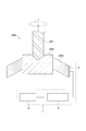
図1に示すように、本実施形態の異常診断装置1は、自動切削機200を異常診断の対象装置としている。
図1に示すように、本実施形態の異常診断装置1は、自動切削機200を異常診断の対象装置としている。
自動切削機200は、ドリル201と、チャック部202とを備える。ドリル201は、切削加工に用いられる刃具である。チャック部202は、加工対象物であるワーク203を保持する保持装置である。自動切削機200は、加工と停止とを繰り返すことで、複数のワーク203を順に加工する。加工時では、ドリル201とワーク203の接触部で発熱する。このため、この接触部からチャック部202へ熱流が流れる。チャック部202から外部へ熱流が流れる。
異常診断装置1は、センサ部2と、制御装置3と、表示装置4とを備えている。
センサ部2は、チャック部202から外部に向かう熱流束を検出する。センサ部2は、チャック部202から外部に向かう熱流束に応じたセンサ信号を制御装置3に向けて出力する。センサ部2は、チャック部202の表面に取り付けられている。センサ部2の構造の詳細については後述する。
制御装置3の入力側に、センサ部2が接続されている。制御装置3は、自動切削機200の異常診断制御を行う。この異常診断制御は、センサ部2の検出結果に基づいて、自動切削機200に異常が有るか否かを判定する制御である。したがって、制御装置3が、熱流束センサ10の検出結果に基づいて、対象装置に異常があるか否かを判定する判定部を構成している。自動切削機200の異常とは、例えば、ドリル201の破損である。
制御装置3の出力側には、表示装置4が接続されている。制御装置3は、異常が有るときに、異常が有ることを表示装置4に表示させる。制御装置3は、マイクロコンピュータ、記憶装置等を有して構成される。
表示装置4は、異常が有ることをユーザに報知するための報知装置である。表示装置4としては、液晶ディスプレイ等が用いられる。
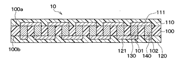
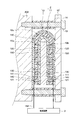
次に、センサ部2の構造について説明する。図2に示すように、センサ部2は、2つの熱流束センサ10と、熱緩衝体11と、放熱体12とを備えている。2つの熱流束センサ10、熱緩衝体11および放熱体12は、いずれも平板状である。
2つの熱流束センサ10の内部構造は同じである。2つの熱流束センサ10の一方が第1熱流束センサ10aである。2つの熱流束センサ10の他方が第2熱流束センサ10bである。
第1熱流束センサ10aは、チャック部202の外面に接して配置されている。第2熱流束センサ10bは、第1熱流束センサ10aに対してチャック部202から離れた側に配置されている。熱緩衝体11は、第1熱流束センサ10aと第2熱流束センサ10bの間に配置されている。放熱体12は、第2熱流束センサ10bに対してチャック部202から離れた側に配置されている。すなわち、センサ部2は、チャック部202に近い側からチャック部202から離れた側に向かって、第1熱流束センサ10a、熱緩衝体11、第2熱流束センサ10b、放熱体12が順に配置されている。
第1熱流束センサ10aは、第1熱流束センサ10aのチャック部202側から熱緩衝体11側に向かって、第1熱流束センサ10aを通過する熱流束に応じた第1センサ信号を出力する。第2熱流束センサ10bは、第2熱流束センサ10bの熱緩衝体11側からその反対側に向かって、第2熱流束センサ10bを通過する熱流束に応じた第2センサ信号を出力する。第1熱流束センサ10aと第2熱流束センサ10bのそれぞれの平面形状は、形と大きさが同じ矩形である。
熱緩衝体11は、所定の熱容量を有している。熱緩衝体11は、金属材料または樹脂材料で構成される。熱緩衝体11は、後述の通り、チャック部202から外部に向かって放出される熱流束の変化を検出できる熱容量となるように、材質や厚さが設定されている。熱緩衝体11の平面形状は、第1熱流束センサ10aの平面形状と形と大きさが同じである。なお、熱緩衝体11の平面形状は、第1熱流束センサ10aの平面形状と形と大きさが異なっていてもよい。
放熱体12は、所定の熱容量を有している。放熱体12は、金属材料または樹脂材料で構成されている。放熱体12は、その熱容量が熱緩衝体11の熱容量よりも大きくなるように、材質や厚さが設定されている。放熱体12の平面形状は、第1熱流束センサ10a、熱緩衝体11、第2熱流束センサ10bの平面形状よりも大きくされている。放熱体12は、第1熱流束センサ10a、熱緩衝体11、第2熱流束センサ10bを挟んだ状態で、チャック部202に固定されている。具体的には、放熱体12の外周部にネジ穴が形成されている。ネジ穴に挿入されたネジ13によって、放熱体12がチャック部202に固定されている。なお、チャック部202と放熱体12との間には、スペーサ14が配置されている。ネジ13は、スペーサ14の内部を貫通している。
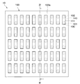
図3、4に示すように、1つの熱流束センサ10は、絶縁基材100、表面保護部材110、裏面保護部材120が一体化され、この一体化されたものの内部で第1、第2熱電部材130、140が交互に直列に接続された構造を有する。なお、図3では、表面保護部材110を省略している。絶縁基材100、表面保護部材110、裏面保護部材120は、フィルム状であって、熱可塑性樹脂等の可撓性を有する樹脂材料で構成されている。絶縁基材100は、その厚さ方向に貫通する複数の第1、第2ビアホール101、102が形成されている。第1、第2ビアホール101、102に互いに異なる金属や半導体等の熱電材料で構成された第1、第2熱電部材130、140が埋め込まれている。絶縁基材100の表面100aに配置された表面導体パターン111によって第1、第2熱電部材130、140の一方の接続部が構成されている。絶縁基材100の裏面100bに配置された裏面導体パターン121によって第1、第2熱電部材130、140の他方の接続部が構成されている。
熱流束センサ10の厚さ方向にて、熱流束が熱流束センサ10を通過すると、第1、第2熱電部材130、140の一方の接続部と他方の接続部に温度差が生じる。これにより、ゼーベック効果によって第1、第2熱電部材130、140に熱起電力が発生する。熱流束センサ10は、この熱起電力、具体的には、電圧をセンサ信号として出力する。
本実施形態では、第1熱流束センサ10aと第2熱流束センサ10bとは、それぞれを通過する熱流束が同じ大きさのとき、絶対値が同じ大きさのセンサ信号を出力するように構成されている。
また、図2に示すように、第1熱流束センサ10aと第2熱流束センサ10bは、互いに直列に接続された状態で、制御装置3に電気的に接続されている。第1熱流束センサ10aと第2熱流束センサ10bは、チャック部202からの熱流束が第1熱流束センサ10aと第2熱流束センサ10bを順に通過したときに、極性が反対の関係を有する第1センサ信号と第2センサ信号を出力するように配置されている。
具体的には、第1、第2熱流束センサ10a、10bは、互いの表面保護部材110が対向するように配置されている。そして、図示していないが、第1、第2熱流束センサ10a、10bの表面導体パターン111同士が外部配線151を介して接続されている。第1、第2熱流束センサ10a、10bのそれぞれの裏面導体パターン121が外部配線152を介して制御装置3と接続されている。これにより、熱流束が第1熱流束センサ10aを裏面保護部材120側から表面保護部材110側に通過する場合には、当該熱流束が第2熱流束センサ10bを表面保護部材110側から裏面保護部材120側に通過するため、第1、第2熱流束センサ10a、10bから出力される第1、第2センサ信号の極性が反対となる。
なお、本実施形態では、第1、第2熱流束センサ10a、10bは、裏面保護部材120側から表面保護部材110側に向かって熱流束が通過した際、正のセンサ信号を出力する。このため、チャック部202側から放熱体12側に向かって熱流束が流れると、第1熱流束センサ10aから正のセンサ信号が出力され、第2熱流束センサ10bから負のセンサ信号が出力される。
そして、センサ部2は、第1センサ信号と第2センサ信号を合わせたセンサ信号を、制御装置3に向けて出力する。このとき、第1、第2熱流束センサ10a、10bを通過する熱流束同士の差が大きいと、センサ部2から出力されるセンサ信号が大きくなる。このような場合としては、例えば、対象物から放出される熱流束が急増したときが該当する。一方、第1、第2熱流束センサ10a、10bを通過する熱流束同士の差が小さいと、センサ部2から出力される出力が小さくなる。このような場合としては、例えば、対象物から放出される熱流束が減少したときや、対象物から放出される熱流束が一定で、所定時間が経過したときが該当する。
次に、制御装置3が行う異常診断制御について説明する。
まず、センサ部2を通過する熱流束およびセンサ部2から出力されるセンサ信号について説明する。
自動切削機200は、1つのワーク203の加工が終わると、次のワーク203の加工準備が完了するまで、停止状態で待機する。次のワーク203の加工準備が完了すると、次のワーク203の加工を開始する。このように、自動切削機200は、加工と停止を1サイクルとする稼働サイクルを繰り返す。
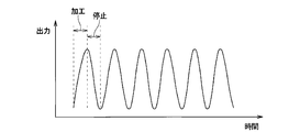
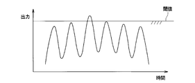
ドリル201の刃が正常な状態のとき、加工中はセンサ部2の出力値が増加し、次の加工までの待機中はセンサ部2の出力値が低下する。このため、図5に示すように、時間経過に伴うセンサ部2の出力値の変化を示す波形は、自動切削機200の稼働サイクルにそって規則的に増減する波形になる。
この理由は、次の通りである。加工中は、チャック部202を流れる熱流束が増大する。加工が終了すると、チャック部202を流れる熱流束が減少する。このとき、図2に示すように、第1熱流束センサ10aは、チャック部202からの熱流束を遮るものがない。このため、第1熱流束センサ10aを通過する熱流束は、チャック部202を流れる熱流束と同様に増減する。一方、図2に示すように、第2熱流束センサ10bは、第1熱流束センサ10a側に熱緩衝体11が配置されている。熱緩衝体11は畜熱と放熱とを行う。このため、第2熱流束センサ10bを熱流束が通過しない。または、第2熱流束センサ10bを通過する熱流束は、第1熱流束センサ10aを通過する熱流束に対して遅れて緩やかに増減する。センサ部2から制御装置3に向けて出力されるセンサ信号は、第1センサ信号と第2センサ信号を合わせたものである。このため、センサ部2の出力値は、自動切削機200の稼働サイクルにそって規則的に増減する。
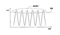
一方、加工中にドリル201の刃に突発的異常、例えば、破損が生じたとき、ワーク203とドリル201がこすれて、異常発熱が起きる。このため、図6に示すように、ドリル201の刃に突発的異常が生じたときでは、出力値が上昇して正常時よりも大きくなる。このことから、正常時と突発的異常時とを判別するための閾値を予め設定しておき、センサ部2の出力値と閾値とを比較する。これにより、突発的異常の有無を判定できる。
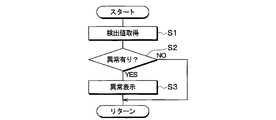
そこで、図7に示すように、制御装置3は、センサ部2の検出結果に基づいて、異常診断を行う。なお、図7中に示した各ステップは、各種機能を実現する機能実現部を構成するものである。
具体的には、制御装置3は、ステップS1で、センサ部2の検出値を取得する。ここでは、制御装置3は、所定の時刻におけるセンサ部2の出力値(具体的には、電圧値)を取得する。なお、センサ部2の出力値をそのまま用いる替わりに、出力値を補正した補正値を検出値として取得してもよい。
続いて、制御装置3は、ステップS2で、検出値と閾値とを比較して、異常が有るか否かを判定する。ここでは、図6に示す時間T1のときのように、検出値が閾値を超えていない場合、異常が無いと判定する。異常が無いと判定した場合、再び、制御装置3は、ステップS1を行う。一方、図6に示す時間T2のときのように、検出値が閾値を超えている場合、制御装置3は、異常が有ると判定する。
異常が有ると判定した場合、制御装置3は、ステップS3で、表示装置4に異常が有ることの表示をさせるための制御信号を出力する。これにより、保守作業員に異常を報知する。この結果、保守作業員が必要な措置、すなわち、ドリル201の交換を施すことができる。
以上の説明の通り、本実施形態の異常診断装置1は、チャック部202から外部に向かって流れる熱流束を検出するセンサ部2と、ドリル201の異常を判定する制御装置3とを備えている。チャック部202から流れる熱流束は、ドリル201とワーク203の接触部での発熱によって生じたものである。センサ部2においては、第1熱流束センサ10aと第2熱流束センサ10bの間に熱緩衝体11が配置されている。熱緩衝体11は熱の蓄積と放出を行う。このため、チャック部202から放出される熱流束が変化したとき、第2熱流束センサ10bを通過する熱流束は、第1熱流束センサ10aを通過する熱流束よりも、遅れて緩やかに変化する。したがって、第1センサ信号と第2センサ信号の相違より、チャック部202から放出される熱流束の変化を検出できる。
ところで、本実施形態のセンサ部2の替わりに、1つの熱流束センサ10のみを用いても、チャック部202から放出される熱流束を検出することができる。
しかし、この場合、チャック部202の周りの環境温度が変化すると、環境温度の影響を受けて、熱流束センサ10を通過する熱流束も変化する。すなわち、ドリル201とワーク203の接触部での発熱量が変わらなくても、環境温度が低下すると、熱流束センサ10を通過する熱流束が増加する。
このため、図8に示すように、ドリル201の刃が正常な状態であっても、一日の環境温度の変動によって、センサ部2の出力値が閾値を超えてしまう場合がある。この場合、制御装置3は、ドリル201の刃が異常であると誤判定してしまう。また、この誤判定を回避するために、環境温度の変動を考慮して、閾値を高く設定することが考えられる。しかし、この場合では、ドリル201の刃が破損しても、正常と誤判定してしまう。すなわち、ドリル201の異常検出の感度が低下してしまう。
これに対して、本実施形態のセンサ部2の第1熱流束センサ10aと第2熱流束センサ10bは、熱緩衝体11の両側に配置されている。したがって、両者は比較的近い位置に配置されている。また、センサ部2の周りの環境温度の変化は、通常、一日という長期間にわたって緩やかに生じる。このため、第1熱流束センサ10aと第2熱流束センサ10bの間に熱緩衝体11が配置されていても、第1熱流束センサ10aと第2熱流束センサ10bが環境温度から受ける影響は同じまたは同じに近い。第1熱流束センサ10aと第2熱流束センサ10bのそれぞれは、同じ環境温度の影響を受けた熱流束に応じたセンサ信号を出力する。第1熱流束センサ10aと第2熱流束センサ10bにおいて、同じ熱流束の大きさに対する出力の絶対値を同じである。したがって、第1熱流束センサ10aと第2熱流束センサ10bの出力の和を用いることで、センサ部2の検出結果に対する環境温度の影響を除外(すなわち、キャンセル)できる。
このため、ドリル201の刃が正常な状態のときのセンサ部2の出力波形は、図5に示すように、環境温度の影響が除外されたものとなる。これにより、一日の環境温度の変動による誤判定を回避できる。また、環境温度の変動を考慮して、閾値を高く設定する必要がなくなる。
よって、本実施形態の異常診断装置1によれば、自動切削機200の異常診断を高精度に行うことができる。なお、第1熱流束センサ10aと第2熱流束センサ10bにおいて、同じ熱流束の大きさに対する出力の絶対値は必ずしも同じでなくてもよい。両者の出力の絶対値が近ければよい。この場合でも、第1熱流束センサ10aと第2熱流束センサ10bの出力の和を用いることで、センサ部2の検出結果に対する環境温度の影響を低減できる。
また、本実施形態のセンサ部2において、第1熱流束センサ10aと第2熱流束センサ10bは、チャック部202からの熱流束が第1熱流束センサ10aと第2熱流束センサ10bを順に通過したときに、極性が反対の関係を有する第1センサ信号と第2センサ信号を出力する。第1熱流束センサ10aと第2熱流束センサ10bは、互いに直列に接続された状態で、制御装置3に電気的に接続されている。これにより、第1センサ信号と第2センサ信号を合わせたセンサ信号を、センサ部2から制御装置3に向けて出力することができる。このため、制御装置3での第1センサ信号と第2センサ信号の和の演算を省略できる。すなわち、制御装置3の演算処理を簡素化できる。
ところで、センサ部2は、放熱体12を持たない構成であってもよい。しかし、センサ部2が放熱体12を持たない場合、第2熱流束センサ10bの表面に風が当たる等の理由により、第2熱流束センサ10bの表面温度が瞬間的に変化してしまう。これが、センサ部2を通過する熱流束に影響する。このため、センサ部2の熱流束の検出精度が低下してしまう。
これに対して、本実施形態のセンサ部2は、所定の熱容量を有する放熱体12を備えている。これにより、短期間でセンサ部2の表面温度が変化する場合であっても、放熱体12での蓄熱と放熱によって、第2熱流束センサ10bの温度変化の発生を抑制できる。このため、センサ部2の熱流束の検出精度を向上させることができる。
また、本実施形態のセンサ部2において、放熱体12の熱容量は、熱緩衝体11の熱容量よりも大きくされている。これにより、チャック部202から大きな熱が放出されたときでも、チャック部202から放熱体12に向かって熱を流すことができる。このため、センサ部2の内部に熱がこもることを抑制できる。
(第2実施形態)
図9に示すように、本実施形態の異常診断装置1は、移送装置300を異常診断の対象装置としている。
図9に示すように、本実施形態の異常診断装置1は、移送装置300を異常診断の対象装置としている。
図9、10に示すように、移送装置300は、ボールねじ301と、支持部材302と、モータ303と、台座304と、レール305と、ガイドブロック306とを備える。なお、図10では、理解をし易くするために、支持部材302を省略して示してある。
ボールねじ301は、回転運動を直線運動に変換する機械要素部品である。ボールねじ301は、ねじ軸311と、ナット312と、ボール313とを有している。ねじ軸311とナット312の間にボール313が入れられている。ねじ軸311が回転すると、ナット312が直線運動をする。支持部材302は、ねじ軸311の軸方向の両端部を支持している。モータ303は、ねじ軸311を回転させる動力源である。
台座304は、移送したい装置等を搭載するためのものである。台座304は、ねじ軸311の軸方向と直交する方向(すなわち、図9の上下方向)を長手方向とする平面矩形状とされている。台座304は、長手方向の略中央部がナット312と連結されている。台座304は、長手方向の両端部がガイドブロック306と連結されている。レール305は、直線状部材である。レール305は、2本用いられており、図10に示すように、ベースプレート307に固定されている。ガイドブロック306は、レール305に係合されている。ガイドブロック306は、レール305に沿って移動するガイド部材である。ガイドブロック306は、レール305に対して摺動する。
このような移送装置300は、モータ303によってねじ軸311が回転すると、台座304がナット312と共にレール305に沿って走行する。これにより、所望箇所に台座304を移送することできる。
本実施形態の異常診断装置1の構成は、第1実施形態の異常診断装置1と同じである。センサ部2は、移送装置300のガイドブロック306の表面に取り付けられている。センサ部2は、図示しないが、ガイドブロック306に近い側からガイドブロック306から離れた側に向かって、第1熱流束センサ10a、熱緩衝体11、第2熱流束センサ10b、放熱体12が順に配置されている。
次に、本実施形態の異常診断制御について説明する。
まず、センサ部2から出力されるセンサ信号について説明する。移送装置300は、台座304の走行と停止を1サイクルとする稼働サイクルを繰り返す。台座304の走行中は、ガイドブロック306の摺動部の摩擦によって、センサ部2の出力値が増加する。台座304の停止中は、センサ部2の出力値が低下する。
このため、図11に示すように、ガイドブロック306の摺動部が正常な状態のとき、時間経過に伴うセンサ部2の出力値の変化を示す波形は、移送装置300の稼働サイクルにそって規則的に増減する波形になる。
一方、ガイドブロック306の摺動部の摩耗が進むにつれて、摺動部の摺動抵抗が上がる。このため、台座304の走行中に摺動部の摩擦によって生じる発熱量が徐々に多くなる。この結果、ガイドブロック306に摩耗による経年的異常、すなわち、摩耗異常が生じたとき、図12に示すように、出力値が上昇して正常時よりも大きくなる。このことから、正常時と経年的異常時とを判別するための閾値を予め設定しておき、センサ部2の出力値と閾値とを比較することで経年的異常の有無を判定できる。
そこで、本実施形態においても、第1実施形態と同様に、制御装置3は、センサ部2の検出結果に基づいて、異常診断を行う。具体的には、制御装置3は、センサ部2の検出値と閾値とを比較する。図12中の波線のように、検出値が閾値を超えていない場合、制御装置3は、異常が無いと判定する。一方、図12中の実線のように、検出値が閾値を超えている場合、制御装置3は、異常が有ると判定する。このようにして、本実施形態の異常診断装置1によれば、移送装置300の経年的異常の有無を診断することができる。
ところで、本実施形態のセンサ部2の替わりに、1つの熱流束センサ10のみを用いても、ガイドブロック306から放出される熱流束を検出することができる。
しかし、この場合、第1実施形態での説明と同様に、ガイドブロック306の周りの環境温度が変化すると、環境温度の影響を受けて、熱流束センサ10を通過する熱流束も変化する。すなわち、ガイドブロック306の摺動部での発熱量が変わらなくても、環境温度が低下すると、熱流束センサ10を通過する熱流束が増加する。
このため、図13に示すように、ガイドブロック306が正常な状態であっても、一日の環境温度の変動によって、センサ部2の出力値が閾値を超えてしまう場合がある。この場合、制御装置3は、ガイドブロック306が異常であると誤判定してしまう。また、この誤判定を回避するために、環境温度の変動を考慮して、閾値を高く設定することが考えられる。しかし、この場合では、ガイドブロック306が異常となっても、正常と誤判定してしまう。すなわち、ガイドブロック306の異常検出の感度が低下してしまう。
これに対して、本実施形態のセンサ部2によれば、第1熱流束センサ10aと第2熱流束センサ10bの出力の和を用いることで、センサ部2の検出結果に対する環境温度の影響を除外できる。
このため、ガイドブロック306の摺動部が正常な状態のときのセンサ部2の出力波形は、図10に示すように、環境温度の影響が除外されたものとなる。これにより、一日の環境温度の変動による誤判定を回避できる。また、環境温度の変動を考慮して、閾値を高く設定する必要がなくなる。
よって、本実施形態の異常診断装置1によれば、移送装置300の異常診断を高精度に行うことができる。
(第3実施形態)
本実施形態は、第1実施形態に対して、センサ部2の構成を変更したものである。異常診断装置1のその他の構成は第1実施形態と同じである。
本実施形態は、第1実施形態に対して、センサ部2の構成を変更したものである。異常診断装置1のその他の構成は第1実施形態と同じである。
図14に示されるように、本実施形態のセンサ部2は、平板状の受熱体16を有している。受熱体16は、第1熱流束センサ10aよりもチャック部202側に配置されている。すなわち、受熱体16は、チャック部202と第1熱流束センサ10aとの間に配置されている。
受熱体16は、熱緩衝体11や放熱体12と同様に、所定の熱容量を有している。受熱体16は、金属材料または樹脂材料で構成される。受熱体16は、その熱容量が熱緩衝体11および放熱体12より小さくなるように、材質や厚さが設定されている。受熱体16の平面形状は、第1熱流束センサ10aの平面形状と形と大きさが同じである。なお、受熱体16の平面形状は、第1熱流束センサ10aの平面形状と形と大きさが異なっていてもよい。
本実施形態のセンサ部2では、受熱体16の蓄熱と放熱によって、検出目的ではないノイズ等の短期的に生じる熱流束の変化が第1、第2熱流束センサ10a、10bに影響することを抑制できる。
また、本実施形態のセンサ部2では、受熱体16の熱容量を小さく設定している。このため、本実施形態のセンサ部2は、検出目的であるドリル201の作動と停止による熱流束変化を検出できる。すなわち、本実施形態のセンサ部2では、受熱体16の熱容量は、ドリル201の作動と停止による熱流束変化を検出できる大きさに設定されている。
よって、本実施形態の異常診断装置1は、自動切削機200の異常診断をより高精度に行うことができる。なお、第2実施形態においても、センサ部2が受熱体16を有する構成としてもよい。これにより、本実施形態と同様の効果を奏する。
(第4実施形態)
本実施形態は、第1実施形態に対して、センサ部2の構成を変更したものである。異常診断装置1のその他の構成は第1実施形態と同じである。
本実施形態は、第1実施形態に対して、センサ部2の構成を変更したものである。異常診断装置1のその他の構成は第1実施形態と同じである。
図15に示されるように、本実施形態のセンサ部2は、第1、第2熱流束センサ10a、10bが、折り曲げられた形状を有する屈曲形状部10cを介して、つながっている。屈曲形状部10cは、第1、第2熱流束センサ10a、10bと同様に、絶縁基材100、表面保護部材110、裏面保護部材120が積層された構造である。このように、本実施形態のセンサ部2は、第1、第2熱流束センサ10a、10bが一体化されている。
換言すると、本実施形態のセンサ部2は、1つの熱流束センサ10が熱緩衝体11を挟むように折り曲げられた構造を有する。熱流束センサ10は、上述の通り、絶縁基材100、表面保護部材110、裏面保護部材120がそれぞれ可撓性を有する樹脂材料で構成されている。このため、熱流束センサ10を容易に折り曲げることができる。これにより、第1熱流束センサ10aと第2熱流束センサ10bの間に熱緩衝体11が配置された構成が実現されている。
第1、第2熱流束センサ10a、10bは、互いの裏面導体パターン121同士がつながっている。第1、第2熱流束センサ10a、10bは、外部配線151ではなく、熱流束センサ10の内部の配線パターンによって電気的に接続されている。なお、第1、第2熱流束センサ10a、10bは、互いの表面導体パターン111同士がつながっていてもよい。
これによれば、第1、第2熱流束センサ10a、10bを1つの熱流束センサ10で構成しており、第1熱流束センサ10aと第2熱流束センサ10bとを接続するための外部配線151を無くすことができる。したがって、部品点数の削減を図ることができる。
(他の実施形態)
本発明は上記した実施形態に限定されるものではなく、下記のように、特許請求の範囲に記載した範囲内において適宜変更が可能である。
本発明は上記した実施形態に限定されるものではなく、下記のように、特許請求の範囲に記載した範囲内において適宜変更が可能である。
(1)第1実施形態では、異常診断装置1が、自動切削機200の破損という突発的な異常の有無を診断したが、自動切削機200以外の他の設備に生じる突発的な異常の有無についても同様に診断することができる。診断可能な対象装置は、所定のサイクルで、発熱量の増減が起きることで、熱流束が変化する装置である。
(2)第2実施形態では、異常診断装置1が、移送装置300の摩耗異常という経年的な異常の有無を診断したが、移送装置300以外の他の設備に生じる経年的な異常の有無についても同様に診断することができる。診断可能な対象装置は、所定のサイクルで、発熱量の増減が起きることで、熱流束が変化する装置である。経年的な異常としては、摺動部の摩耗、摺動部の潤滑剤不足等が挙げられる。
(3)第1~第3実施形態のセンサ部2では、第1熱流束センサ10aと第2熱流束センサ10bが、互いに直列に接続された状態で、制御装置3に電気的に接続されていたが、制御装置3に対して並列に接続されていてもよい。
また、第1~第3実施形態のセンサ部2では、極性が反対の関係を有する第1センサ信号と第2センサ信号を出力するように、第1熱流束センサ10aと第2熱流束センサ10bが配置されていたが、第1熱流束センサ10aと第2熱流束センサ10bの配置はこれに限定されない。極性が同じ第1センサ信号と第2センサ信号を出力するように、第1熱流束センサ10aと第2熱流束センサ10bが配置されていてもよい。この場合、第1熱流束センサ10aと第2熱流束センサ10bは、制御装置3に対して並列に接続される。また、異常診断制御においては、制御装置3は、第1センサ信号と第2センサ信号の差を演算する。これにより、第1、第2実施形態と同様に、異常診断制御を行うことができる。
(4)第1~第3実施形態のセンサ部2においては、熱流束センサ10の絶縁基材100、表面保護部材110、裏面保護部材120が、樹脂材料以外の可撓性を有する絶縁材料で構成されていてもよい。さらに、絶縁基材100、表面保護部材110、裏面保護部材120が、可撓性を持たない絶縁材料で構成されていてもよい。また、熱流束センサ10が、表面保護部材110、裏面保護部材120を持たない構造であってもよい。また、熱流束センサ10として、上記した構成とは別の構成のものを用いてもよい。
(5)第4実施形態のセンサ部2においては、熱流束センサ10の絶縁基材100、表面保護部材110、裏面保護部材120が、樹脂材料以外の可撓性を有する絶縁材料で構成されていてもよい。また、熱流束センサ10が、表面保護部材110、裏面保護部材120を持たない構造であってもよい。この場合、第1熱流束センサ10aと第2熱流束センサ10bは、絶縁基材100で構成された屈曲形状部10cを介して、つながっている構造となる。要するに、屈曲形状部10cは、絶縁基材100と同じ絶縁材料を含んで構成されていればよい。
(6)上記各実施形態のセンサ部2は、2つの熱流束センサ10と、熱緩衝体11と、放熱体12とを備えていたが、放熱体12を備えていなくてもよい。この場合、センサ部2の固定は、固定部材を用いたり、接着剤を用いたりして行われる。
(7)上記各実施形態では、センサ部2のセンサ信号として電圧を用いたが、電流を用いてもよい。
(8)上記各実施形態は、互いに無関係なものではなく、組み合わせが明らかに不可な場合を除き、適宜組み合わせが可能である。また、上記各実施形態において、実施形態を構成する要素は、特に必須であると明示した場合および原理的に明らかに必須であると考えられる場合等を除き、必ずしも必須のものではないことは言うまでもない。
(まとめ)
上記各実施形態の一部または全部で示された第1の観点によれば、異常診断装置は、センサ部と、判定部とを備える。センサ部は、第1熱流束センサと、第2熱流束センサと、第1熱流束センサと第2熱流束センサの間に配置された熱緩衝体とを有する。第1熱流束センサは、第1熱流束センサを通過する熱流束に応じた第1センサ信号を出力する。第2熱流束センサは、第2熱流束センサを通過する熱流束に応じた第2センサ信号を出力する。判定部は、第1センサ信号と第2センサ信号に基づいて、対象装置の異常の有無を判定する。
(まとめ)
上記各実施形態の一部または全部で示された第1の観点によれば、異常診断装置は、センサ部と、判定部とを備える。センサ部は、第1熱流束センサと、第2熱流束センサと、第1熱流束センサと第2熱流束センサの間に配置された熱緩衝体とを有する。第1熱流束センサは、第1熱流束センサを通過する熱流束に応じた第1センサ信号を出力する。第2熱流束センサは、第2熱流束センサを通過する熱流束に応じた第2センサ信号を出力する。判定部は、第1センサ信号と第2センサ信号に基づいて、対象装置の異常の有無を判定する。
また、第2の観点によれば、センサ部は、第2熱流束センサよりも対象装置から離れた側に配置され、所定の熱容量を有する放熱体を有する。
これによると、短期間でセンサ部の表面温度が変化する場合であっても、放熱体での蓄熱と放熱によって、第2熱流束センサの温度変化の発生を抑制できる。このため、センサ部の熱流束の検出精度を向上させることができる。
また、第3の観点によれば、放熱体の熱容量は、熱緩衝体の熱容量よりも大きくされている。これによると、対象装置から大きな熱が放出されたときでも、対象装置から放熱体に向かって熱を流すことができる。このため、センサ部の内部に熱がこもることを抑制できる。
また、第4の観点によれば、センサ部は、第1熱流束センサよりも対象装置側に配置された受熱体を有している。受熱体の熱容量は、熱緩衝体の熱容量よりも小さくされている。
これによると、受熱体の蓄熱と放熱によって、検出目的ではないノイズ等の短期的に生じる熱流束の変化が第1、第2熱流束センサに影響することを抑制できる。また、受熱体の熱容量を小さく設定することで、センサ部によって検出目的である対象装置から放出される熱流束の変化を検出できる。
また、第5の観点によれば、センサ部は、対象装置からの熱流束が第1熱流束センサと第2熱流束センサを順に通過したときに、第1センサ信号と第2センサ信号の極性が反対となるように、第1熱流束センサと第2熱流束センサとが配置されている。第1熱流束センサと第2熱流束センサは、電気的に直列に接続されている。
これによると、センサ部は、第1センサ信号と第2センサ信号を合わせたセンサ信号を出力することができる。このため、第1センサ信号と第2センサ信号の和の演算処理を不要にできる。
また、第6の観点によれば、第1熱流束センサと第2熱流束センサのそれぞれは、可撓性を有するフィルム状の絶縁基材と、複数の第1熱電部材と、複数の第2熱電部材とを有して構成される。複数の第1熱電部材と複数の第2熱電部材は、第1熱電部材と第2熱電部材とが交互に直列に接続されている。第1熱流束センサと第2熱流束センサは、絶縁材料を含んで構成された屈曲形状部を介して、つながっている。
これによると、第1熱流束センサと第2熱流束センサとを接続するための外部配線を不要にできる。
1 異常診断装置
2 センサ部
3 制御装置
10a 第1熱流束センサ
10b 第2熱流束センサ
10c 屈曲形状部
11 熱緩衝体
12 放熱体
16 受熱体
2 センサ部
3 制御装置
10a 第1熱流束センサ
10b 第2熱流束センサ
10c 屈曲形状部
11 熱緩衝体
12 放熱体
16 受熱体
Claims (6)
- 対象装置(200、300)の異常を診断する異常診断装置であって、
前記対象装置に設置され、前記対象装置から外部に向かって流れる熱流束を検出するセンサ部(2)と、
前記対象装置の異常を判定する判定部(3)とを備え、
前記センサ部は、
第1熱流束センサ(10a)と、
前記第1熱流束センサよりも前記対象装置から離れた側に配置された第2熱流束センサ(10b)と、
前記第1熱流束センサと前記第2熱流束センサの間に配置され、所定の熱容量を有する熱緩衝体(11)とを有し、
前記第1熱流束センサは、前記対象装置側から前記熱緩衝体側に向かって前記第1熱流束センサを通過する熱流束に応じた第1センサ信号を出力し、
前記第2熱流束センサは、前記熱緩衝体側から前記熱緩衝体側の反対側に向かって前記第2熱流束センサを通過する熱流束に応じた第2センサ信号を出力し、
前記判定部は、前記第1センサ信号と前記第2センサ信号に基づいて、前記対象装置の異常の有無を判定する異常診断装置。 - 前記センサ部は、前記第2熱流束センサよりも前記対象装置から離れた側に配置され、所定の熱容量を有する放熱体(12)を有する請求項1に記載の異常診断装置。
- 前記放熱体の熱容量は、前記熱緩衝体の熱容量よりも大きくされている請求項2に記載の異常診断装置。
- 前記センサ部は、前記第1熱流束センサよりも前記対象装置側に配置された受熱体(16)を有し、
前記受熱体の熱容量は、前記熱緩衝体の熱容量よりも小さくされている請求項1ないし3のいずれか1つに記載の異常診断装置。 - 前記センサ部は、前記対象装置からの熱流束が前記第1熱流束センサと前記第2熱流束センサを順に通過したときに、前記第1センサ信号と前記第2センサ信号の極性が反対となるように、前記第1熱流束センサと前記第2熱流束センサとが配置されており、
前記第1熱流束センサと前記第2熱流束センサは、電気的に直列に接続されている請求項1ないし4のいずれか1つに記載の異常診断装置。 - 前記第1熱流束センサと前記第2熱流束センサのそれぞれは、
少なくとも絶縁材料で構成され、可撓性を有するフィルム状の絶縁基材(100)と、
前記絶縁基材に形成され、熱電材料で構成された複数の第1熱電部材(130)と、
前記絶縁基材に形成され、前記第1熱電部材と異なる熱電材料で構成された複数の第2熱電部材(140)とを有し、
前記複数の第1熱電部材と複数の前記第2熱電部材は、前記第1熱電部材と前記第2熱電部材とが交互に直列に接続されており、
前記第1熱流束センサと前記第2熱流束センサは、前記絶縁材料を含んで構成された屈曲形状部(10c)を介して、つながっている請求項5に記載の異常診断装置。
Priority Applications (5)
| Application Number | Priority Date | Filing Date | Title |
|---|---|---|---|
| US15/775,761 US10788379B2 (en) | 2015-11-12 | 2016-11-10 | Abnormality diagnosis apparatus |
| KR1020187013555A KR102059644B1 (ko) | 2015-11-12 | 2016-11-10 | 이상 진단 장치 |
| CN201680065807.0A CN108351277B (zh) | 2015-11-12 | 2016-11-10 | 异常诊断装置 |
| EP20168775.3A EP3699567A1 (en) | 2015-11-12 | 2016-11-10 | Abnormality diagnosis apparatus |
| EP16864285.8A EP3376200A4 (en) | 2015-11-12 | 2016-11-10 | Abnormality diagnostic device |
Applications Claiming Priority (2)
| Application Number | Priority Date | Filing Date | Title |
|---|---|---|---|
| JP2015222446A JP6249009B2 (ja) | 2015-11-12 | 2015-11-12 | 異常診断装置 |
| JP2015-222446 | 2015-11-12 |
Publications (1)
| Publication Number | Publication Date |
|---|---|
| WO2017082324A1 true WO2017082324A1 (ja) | 2017-05-18 |
Family
ID=58695429
Family Applications (1)
| Application Number | Title | Priority Date | Filing Date |
|---|---|---|---|
| PCT/JP2016/083305 Ceased WO2017082324A1 (ja) | 2015-11-12 | 2016-11-10 | 異常診断装置 |
Country Status (7)
| Country | Link |
|---|---|
| US (1) | US10788379B2 (ja) |
| EP (2) | EP3699567A1 (ja) |
| JP (1) | JP6249009B2 (ja) |
| KR (1) | KR102059644B1 (ja) |
| CN (1) | CN108351277B (ja) |
| TW (1) | TWI619935B (ja) |
| WO (1) | WO2017082324A1 (ja) |
Cited By (1)
| Publication number | Priority date | Publication date | Assignee | Title |
|---|---|---|---|---|
| CN115237177A (zh) * | 2022-08-03 | 2022-10-25 | 中国科学技术大学 | 一种基于主被动复合一体的宽频段温度噪声抑制方法 |
Families Citing this family (5)
| Publication number | Priority date | Publication date | Assignee | Title |
|---|---|---|---|---|
| JP6358233B2 (ja) | 2015-11-12 | 2018-07-18 | 株式会社デンソー | 組付状態の診断装置 |
| JP6358234B2 (ja) | 2015-11-12 | 2018-07-18 | 株式会社デンソー | 稼働状態の診断装置 |
| JP6988469B2 (ja) * | 2017-12-27 | 2022-01-05 | 株式会社デンソー | 歪み検出装置およびそれを用いた診断装置 |
| JP6988468B2 (ja) * | 2017-12-27 | 2022-01-05 | 株式会社デンソー | 締結部材一体型歪み検出装置およびそれを用いた診断装置 |
| CN113227577B (zh) * | 2018-12-27 | 2023-03-24 | 三菱电机株式会社 | 异常诊断装置及异常诊断方法 |
Citations (3)
| Publication number | Priority date | Publication date | Assignee | Title |
|---|---|---|---|---|
| JPH03213249A (ja) * | 1990-01-16 | 1991-09-18 | Omron Corp | 熱流計測を利用した工具のモニタリング方法 |
| CN102879419A (zh) * | 2011-07-15 | 2013-01-16 | 郭晓明 | 一种建筑保温材料的监控系统 |
| JP2015175671A (ja) * | 2014-03-13 | 2015-10-05 | オムロン株式会社 | 内部温度測定方法及び内部温度測定装置 |
Family Cites Families (22)
| Publication number | Priority date | Publication date | Assignee | Title |
|---|---|---|---|---|
| JPS5376086A (en) | 1976-12-17 | 1978-07-06 | Glory Kogyo Kk | Machine for counting paper web and like |
| US4779994A (en) | 1987-10-15 | 1988-10-25 | Virginia Polytechnic Institute And State University | Heat flux gage |
| JPH05301144A (ja) * | 1992-04-23 | 1993-11-16 | Suzuki Motor Corp | 工作機械の暖機装置 |
| JPH07229865A (ja) * | 1994-02-22 | 1995-08-29 | Hitachi Ltd | 管内付着物の検出装置 |
| JP2001165782A (ja) * | 1999-12-10 | 2001-06-22 | Mitsubishi Heavy Ind Ltd | 熱流束測定ゲージ |
| EP1565720B1 (en) * | 2002-10-15 | 2015-11-18 | Danfoss A/S | A method for detecting an abnormality of a heat exchanger |
| DE102006016956B4 (de) * | 2006-04-11 | 2009-10-08 | Electrolux Home Products Corp. N.V. | Verfahren zum Bestimmen der von einem Gargut aufgenommenen Wärme in einem Gargerät und Gargerät zur Durchführung des Verfahrens |
| JP2008057670A (ja) * | 2006-08-31 | 2008-03-13 | F C C:Kk | クラッチの発熱量推定装置 |
| US7368827B2 (en) * | 2006-09-06 | 2008-05-06 | Siemens Power Generation, Inc. | Electrical assembly for monitoring conditions in a combustion turbine operating environment |
| DE102006061794B3 (de) * | 2006-12-21 | 2008-04-30 | Thermosensorik Gmbh | Verfahren zur automatischen Prüfung einer Schweißverbindung |
| JP5139428B2 (ja) * | 2007-05-31 | 2013-02-06 | 住友重機械工業株式会社 | 射出成形機の表示装置 |
| US8606554B2 (en) * | 2009-10-19 | 2013-12-10 | Siemens Aktiengesellschaft | Heat flow model for building fault detection and diagnosis |
| JP2014007376A (ja) * | 2012-05-30 | 2014-01-16 | Denso Corp | 熱電変換装置 |
| JP5376087B1 (ja) | 2012-05-30 | 2013-12-25 | 株式会社デンソー | 熱電変換装置の製造方法 |
| JP5662381B2 (ja) * | 2012-06-15 | 2015-01-28 | 日立オートモティブシステムズ株式会社 | 熱式流量計 |
| JP5761302B2 (ja) * | 2013-06-04 | 2015-08-12 | 株式会社デンソー | 車両用の快適温調制御装置 |
| JP5942960B2 (ja) | 2013-06-04 | 2016-06-29 | 株式会社デンソー | 発熱量制御装置 |
| US9350319B2 (en) * | 2014-02-24 | 2016-05-24 | Siemens Energy, Inc. | Self-powered sensing and transmitting device and method of fabricating the same |
| JP6303973B2 (ja) | 2014-10-20 | 2018-04-04 | 株式会社デンソー | 状態検出センサ |
| FR3028314B1 (fr) * | 2014-11-07 | 2016-12-23 | Aircelle Sa | Procede de caracterisation du vieillissement thermique de materiaux composites, en particulier de materiaux composites a matrice organique |
| JP6358233B2 (ja) * | 2015-11-12 | 2018-07-18 | 株式会社デンソー | 組付状態の診断装置 |
| JP6763142B2 (ja) * | 2015-12-28 | 2020-09-30 | セイコーエプソン株式会社 | 内部温度測定装置、リスト装着型装置及び内部温度測定方法 |
-
2015
- 2015-11-12 JP JP2015222446A patent/JP6249009B2/ja active Active
-
2016
- 2016-11-10 KR KR1020187013555A patent/KR102059644B1/ko not_active Expired - Fee Related
- 2016-11-10 WO PCT/JP2016/083305 patent/WO2017082324A1/ja not_active Ceased
- 2016-11-10 US US15/775,761 patent/US10788379B2/en active Active
- 2016-11-10 EP EP20168775.3A patent/EP3699567A1/en not_active Withdrawn
- 2016-11-10 EP EP16864285.8A patent/EP3376200A4/en not_active Ceased
- 2016-11-10 CN CN201680065807.0A patent/CN108351277B/zh not_active Expired - Fee Related
- 2016-11-11 TW TW105136937A patent/TWI619935B/zh not_active IP Right Cessation
Patent Citations (3)
| Publication number | Priority date | Publication date | Assignee | Title |
|---|---|---|---|---|
| JPH03213249A (ja) * | 1990-01-16 | 1991-09-18 | Omron Corp | 熱流計測を利用した工具のモニタリング方法 |
| CN102879419A (zh) * | 2011-07-15 | 2013-01-16 | 郭晓明 | 一种建筑保温材料的监控系统 |
| JP2015175671A (ja) * | 2014-03-13 | 2015-10-05 | オムロン株式会社 | 内部温度測定方法及び内部温度測定装置 |
Non-Patent Citations (1)
| Title |
|---|
| See also references of EP3376200A4 * |
Cited By (2)
| Publication number | Priority date | Publication date | Assignee | Title |
|---|---|---|---|---|
| CN115237177A (zh) * | 2022-08-03 | 2022-10-25 | 中国科学技术大学 | 一种基于主被动复合一体的宽频段温度噪声抑制方法 |
| CN115237177B (zh) * | 2022-08-03 | 2023-03-14 | 中国科学技术大学 | 一种基于主被动复合一体的宽频段温度噪声抑制方法 |
Also Published As
| Publication number | Publication date |
|---|---|
| TWI619935B (zh) | 2018-04-01 |
| EP3376200A8 (en) | 2019-01-23 |
| KR20180066221A (ko) | 2018-06-18 |
| CN108351277B (zh) | 2021-03-23 |
| TW201728889A (zh) | 2017-08-16 |
| EP3699567A1 (en) | 2020-08-26 |
| KR102059644B1 (ko) | 2019-12-26 |
| EP3376200A4 (en) | 2018-11-14 |
| JP2017090320A (ja) | 2017-05-25 |
| US10788379B2 (en) | 2020-09-29 |
| EP3376200A1 (en) | 2018-09-19 |
| US20180372560A1 (en) | 2018-12-27 |
| CN108351277A (zh) | 2018-07-31 |
| JP6249009B2 (ja) | 2017-12-20 |
Similar Documents
| Publication | Publication Date | Title |
|---|---|---|
| JP6249009B2 (ja) | 異常診断装置 | |
| JP6358233B2 (ja) | 組付状態の診断装置 | |
| JP6500825B2 (ja) | 監視装置 | |
| JP6699140B2 (ja) | 異常診断システム | |
| TW201627642A (zh) | 狀態檢測感測器 | |
| JP6358234B2 (ja) | 稼働状態の診断装置 | |
| JP2017090318A5 (ja) | ||
| JP2019168396A (ja) | ボールねじ装置の異常検出装置 | |
| JP2017090319A5 (ja) | ||
| JP2019117154A (ja) | 歪み検出装置およびそれを用いた診断装置 | |
| KR20210048631A (ko) | 베어링용 모니터링 장치 | |
| JP7251438B2 (ja) | 加振機及び疲労・耐久試験装置 |
Legal Events
| Date | Code | Title | Description |
|---|---|---|---|
| 121 | Ep: the epo has been informed by wipo that ep was designated in this application |
Ref document number: 16864285 Country of ref document: EP Kind code of ref document: A1 |
|
| ENP | Entry into the national phase |
Ref document number: 20187013555 Country of ref document: KR Kind code of ref document: A |
|
| NENP | Non-entry into the national phase |
Ref country code: DE |
|
| WWE | Wipo information: entry into national phase |
Ref document number: 2016864285 Country of ref document: EP |