WO2017082341A1 - 軟質ポリウレタンフォーム成形品、およびシート用パッド - Google Patents
軟質ポリウレタンフォーム成形品、およびシート用パッド Download PDFInfo
- Publication number
- WO2017082341A1 WO2017082341A1 PCT/JP2016/083360 JP2016083360W WO2017082341A1 WO 2017082341 A1 WO2017082341 A1 WO 2017082341A1 JP 2016083360 W JP2016083360 W JP 2016083360W WO 2017082341 A1 WO2017082341 A1 WO 2017082341A1
- Authority
- WO
- WIPO (PCT)
- Prior art keywords
- polyurethane foam
- flexible polyurethane
- foam molded
- longitudinal direction
- layer
- Prior art date
- Legal status (The legal status is an assumption and is not a legal conclusion. Google has not performed a legal analysis and makes no representation as to the accuracy of the status listed.)
- Ceased
Links
Images


Classifications
-
- A—HUMAN NECESSITIES
- A47—FURNITURE; DOMESTIC ARTICLES OR APPLIANCES; COFFEE MILLS; SPICE MILLS; SUCTION CLEANERS IN GENERAL
- A47C—CHAIRS; SOFAS; BEDS
- A47C27/00—Spring, stuffed or fluid mattresses or cushions specially adapted for chairs, beds or sofas
- A47C27/14—Spring, stuffed or fluid mattresses or cushions specially adapted for chairs, beds or sofas with foamed material inlays
- A47C27/15—Spring, stuffed or fluid mattresses or cushions specially adapted for chairs, beds or sofas with foamed material inlays consisting of two or more layers
-
- B—PERFORMING OPERATIONS; TRANSPORTING
- B60—VEHICLES IN GENERAL
- B60N—SEATS SPECIALLY ADAPTED FOR VEHICLES; VEHICLE PASSENGER ACCOMMODATION NOT OTHERWISE PROVIDED FOR
- B60N2/00—Seats specially adapted for vehicles; Arrangement or mounting of seats in vehicles
- B60N2/70—Upholstery springs ; Upholstery
- B60N2/7017—Upholstery springs ; Upholstery characterised by the manufacturing process; manufacturing upholstery or upholstery springs not otherwise provided for
-
- A—HUMAN NECESSITIES
- A47—FURNITURE; DOMESTIC ARTICLES OR APPLIANCES; COFFEE MILLS; SPICE MILLS; SUCTION CLEANERS IN GENERAL
- A47C—CHAIRS; SOFAS; BEDS
- A47C27/00—Spring, stuffed or fluid mattresses or cushions specially adapted for chairs, beds or sofas
- A47C27/14—Spring, stuffed or fluid mattresses or cushions specially adapted for chairs, beds or sofas with foamed material inlays
- A47C27/148—Spring, stuffed or fluid mattresses or cushions specially adapted for chairs, beds or sofas with foamed material inlays of different resilience
-
- B—PERFORMING OPERATIONS; TRANSPORTING
- B32—LAYERED PRODUCTS
- B32B—LAYERED PRODUCTS, i.e. PRODUCTS BUILT-UP OF STRATA OF FLAT OR NON-FLAT, e.g. CELLULAR OR HONEYCOMB, FORM
- B32B5/00—Layered products characterised by the non- homogeneity or physical structure, i.e. comprising a fibrous, filamentary, particulate or foam layer; Layered products characterised by having a layer differing constitutionally or physically in different parts
- B32B5/14—Layered products characterised by the non- homogeneity or physical structure, i.e. comprising a fibrous, filamentary, particulate or foam layer; Layered products characterised by having a layer differing constitutionally or physically in different parts characterised by a layer differing constitutionally or physically in different parts, e.g. denser near its faces
- B32B5/145—Variation across the thickness of the layer
-
- B—PERFORMING OPERATIONS; TRANSPORTING
- B32—LAYERED PRODUCTS
- B32B—LAYERED PRODUCTS, i.e. PRODUCTS BUILT-UP OF STRATA OF FLAT OR NON-FLAT, e.g. CELLULAR OR HONEYCOMB, FORM
- B32B5/00—Layered products characterised by the non- homogeneity or physical structure, i.e. comprising a fibrous, filamentary, particulate or foam layer; Layered products characterised by having a layer differing constitutionally or physically in different parts
- B32B5/22—Layered products characterised by the non- homogeneity or physical structure, i.e. comprising a fibrous, filamentary, particulate or foam layer; Layered products characterised by having a layer differing constitutionally or physically in different parts characterised by the presence of two or more layers which are next to each other and are fibrous, filamentary, formed of particles or foamed
- B32B5/32—Layered products characterised by the non- homogeneity or physical structure, i.e. comprising a fibrous, filamentary, particulate or foam layer; Layered products characterised by having a layer differing constitutionally or physically in different parts characterised by the presence of two or more layers which are next to each other and are fibrous, filamentary, formed of particles or foamed at least two layers being foamed and next to each other
-
- B—PERFORMING OPERATIONS; TRANSPORTING
- B60—VEHICLES IN GENERAL
- B60N—SEATS SPECIALLY ADAPTED FOR VEHICLES; VEHICLE PASSENGER ACCOMMODATION NOT OTHERWISE PROVIDED FOR
- B60N2/00—Seats specially adapted for vehicles; Arrangement or mounting of seats in vehicles
- B60N2/70—Upholstery springs ; Upholstery
-
- B—PERFORMING OPERATIONS; TRANSPORTING
- B60—VEHICLES IN GENERAL
- B60N—SEATS SPECIALLY ADAPTED FOR VEHICLES; VEHICLE PASSENGER ACCOMMODATION NOT OTHERWISE PROVIDED FOR
- B60N2/00—Seats specially adapted for vehicles; Arrangement or mounting of seats in vehicles
- B60N2/70—Upholstery springs ; Upholstery
- B60N2/7023—Coach-like constructions
- B60N2/7035—Cushions
-
- B—PERFORMING OPERATIONS; TRANSPORTING
- B32—LAYERED PRODUCTS
- B32B—LAYERED PRODUCTS, i.e. PRODUCTS BUILT-UP OF STRATA OF FLAT OR NON-FLAT, e.g. CELLULAR OR HONEYCOMB, FORM
- B32B2266/00—Composition of foam
- B32B2266/02—Organic
- B32B2266/0214—Materials belonging to B32B27/00
- B32B2266/0278—Polyurethane
-
- B—PERFORMING OPERATIONS; TRANSPORTING
- B32—LAYERED PRODUCTS
- B32B—LAYERED PRODUCTS, i.e. PRODUCTS BUILT-UP OF STRATA OF FLAT OR NON-FLAT, e.g. CELLULAR OR HONEYCOMB, FORM
- B32B2605/00—Vehicles
- B32B2605/003—Interior finishings
Definitions
- the present invention relates to a flexible polyurethane foam molded article and a pad for a sheet.
- This application claims priority based on Japanese Patent Application No. 2015-212442 for which it applied to Japan on November 11, 2015, and uses the content here.
- Patent Document 1 a configuration as shown in Patent Document 1 is known as a flexible polyurethane foam molded article such as a sheet pad having a mounting surface.
- the core layer center layer
- the core layer absorbs vibration and the top layer supports the buttocks. Trying to improve.
- the present invention has been made in view of the above-described circumstances, and an object thereof is to suppress a sense of wobbling while suppressing impairing the sitting feeling.
- a flexible polyurethane foam molded article is a flexible polyurethane foam molded article having a placement surface and obtained by foaming and molding a foaming stock solution in a longitudinal direction perpendicular to the placement surface.
- the entire flexible polyurethane foam molded product is compressed by 15% in the longitudinal direction.
- the remaining thickness ratio in the vertical direction is the lowest among the plurality of layered portions, and among the plurality of layered portions, the flexible polyurethane foam is formed on the back layer located closest to the mounting surface along the vertical direction. When the entire molded product is compressed 50% in the vertical direction, the remaining thickness ratio in the vertical direction becomes the highest among the plurality of layered portions.
- the seat pad 1 of the present embodiment is employed in, for example, a seat (seat portion) attached to an automobile (vehicle), and the seat surface 1A (mounting surface) and the seating surface 1A. And a back surface 1B positioned on the opposite side of the seating surface 1A along the vertical direction Y, which is orthogonal to each other, and is a flexible polyurethane foam molded product obtained by foaming and molding a foam stock solution.
- the foaming stock solution contains, for example, a polyol component, a polyisocyanate component, a crosslinking agent, a foaming agent, and a catalyst.
- the length (thickness) in the longitudinal direction Y of the sheet pad 1 is, for example, 30 mm to 150 mm, preferably 30 mm to 150 mm.
- the sheet pad 1 has a plurality of layered portions L1 to L10 that are layered in the vertical direction Y.
- the sheet pad 1 is formed by foaming one type of foaming stock solution and integrally molding the entire sheet pad 1.
- the plurality of layered portions L1 to L10 are formed by equally dividing (equally dividing) the unloaded sheet pad 1 in the longitudinal direction Y into 3 to 20 layers (10 layers in the illustrated example). ing.
- a plane parallel to the seating surface 1A and the back surface 1B can be employed.
- seat is shape
- the mold 3 is formed in a box shape including a lower mold 31 and an upper mold 32, and the internal space is a cavity C that forms the sheet pad 1.
- the upper die 32 is a lid member that closes the upper end opening of the lower die 31, and an air vent hole 33 penetrating vertically is formed in the outer peripheral portion.
- each of the layered portions L1 to L10 is formed by firing a firing stock solution separately from one material different from each other, and the sheet pad 1 is formed by laminating the layered portions L1 to L10. It may be.
- each of the layered portions L1 to L10 may be formed by laminating a plurality of thin layer bodies formed by foaming a foaming stock solution instead of separately molding each one of different materials.
- the plurality of layered portions includes a plurality of layered portions in which a single sheet pad 1 (soft polyurethane foam molded article) is divided into layers in the longitudinal direction Y as in the present embodiment. Unlike the embodiment, it also includes a layered portion in which a plurality of one-layered portions formed by laminating each other in the vertical direction so as to form one sheet pad.
- the remaining thickness ratio in the direction Y is the lowest among the plurality of layered portions L1 to L10. Further, among the plurality of layered portions L1 to L10, in the back surface layer L10 that is located closest to the back surface 1B (reverse mounting surface side, anti-seating surface side) along the vertical direction Y, the entire seat pad 1 is in the vertical direction. When compressed to Y by 50%, the remaining thickness ratio in the longitudinal direction Y is the highest among the plurality of layered portions L1 to L10.
- the remaining thickness ratio of each of the layered portions L1 to L10 in a state where a predetermined load is applied is the thickness of the layered portions L1 to L10 in an unloaded state. means the ratio (T / T 0) of the thickness at the load applying state for (T 0) (T).
- the difference between the remaining thickness ratio of the surface layer L1 and the remaining thickness ratio of the back surface layer L10 is 20% or more and 36% or less.
- the value of the remaining thickness ratio of each of the layered portions L1 to L10 gradually increases as it goes from the surface layer L1 to the back surface layer L10.
- the difference between the remaining thickness ratio of the surface layer L1 and the remaining thickness ratio of the back surface layer L10 is 31% or more and 47% or less.
- the remaining thickness ratio of the back surface layer L10 is 80% or more.
- the remaining thickness ratio of the surface layer L1 is lowered while decreasing the rate of change.
- the surface layer L1 is easy to compress when the applied load is small, and difficult to compress when the applied load is large.
- the entire sheet pad 1 is greatly compressed in the vertical direction Y, the remaining in at least one layer of the plurality of layered portions L1 to L10 located on the back surface 1B side from the center in the vertical direction Y of the sheet pad 1 The thickness ratio is lowered while increasing the rate of change.
- the center in the longitudinal direction Y of the seat pad 1 is located on the boundary between the fifth layered portion L5 and the sixth layered portion L6 from the seating surface 1A side.
- the layered portion L9 adjacent to the back surface layer L10 that is, the second layered portion from the back surface 1B side.
- the residual thickness ratio in L9 (hereinafter referred to as “back surface adjacent layer L9”) becomes low while increasing the rate of change as described above.
- the back surface adjacent layer L9 is difficult to compress at a stage where the applied load is small, and is easily compressed at a stage where the applied load is large.
- the seating surface 1A and the back surface 1B are compressed over the entire surface, and the seat pad 1 is longitudinal regardless of the position in the lateral direction X along the seating surface 1A.
- Fully compressed in the same direction in the Y direction full compression.
- the influence of the tension that can act in the lateral direction X when the sheet pad 1 is compressed can be effectively eliminated.
- the flexible polyurethane foam which is a material for forming the sheet pad 1, will be described.
- a preferred embodiment of the flexible polyurethane foam is a flexible polyurethane foam obtained by foam molding a foam stock solution containing a polyol, a polyisocyanate, a crosslinking agent, a foaming agent, and a catalyst.
- the following (A) to (C) are mentioned as the characteristics of the material constituting the foaming stock solution.
- polystyrene resin As the polyol component, a polyether polyol having a weight average molecular weight Mw of 3000 to 12000 and a functional group number (number of hydroxyl groups) of 3 to 4 is contained.
- the ethylene oxide group / propylene oxide group (molar ratio) in the entire compound (total cross-linking agent) contained in the foaming stock solution as the cross-linking agent component is 100 or more.
- polyisocyanate 70 or more diphenylmethane diisocyanate (MDI) is contained by an isocyanate equivalent.
- a polyether polyol having a weight average molecular weight Mw of 3000 to 12000 and a functional group number (number of hydroxyl groups) of 3 to 4 is contained.
- the polyether polyol is preferably a polyether polyol obtained by ring-opening polymerization of an alkylene oxide because of good reactivity.
- the alkylene oxide include propylene oxide (PO) and ethylene oxide (EO).
- the alkylene oxide used as the material for the polyether polyol may be one kind or two or more kinds.
- the polyether polyol constituting the foaming stock solution a polyether polyol obtained by using the above PO and EO together is preferable from the viewpoint of raw material activity.
- the blending ratio (molar ratio) of PO and EO is not particularly limited.
- the EO / PO (molar ratio) is preferably 8/92 to 25/75, more preferably 13/87 to 20/80.
- the EO / PO (molar ratio) is in the above range, a polyether polyol having good reactivity can be easily produced.
- the number of hydroxyl groups (functional groups) contained in one molecule of the polyether polyol constituting the foaming stock solution is preferably 3 to 4. Within these preferred ranges, the viscosity of the foamed stock solution becomes moderate, and a flexible polyurethane foam having excellent physical properties can be obtained.
- a polyether polyol having two functional groups may be used in combination as an optional component.
- the weight average molecular weight Mw of the polyether polyol constituting the foaming stock solution is preferably 3000 to 12000, more preferably 3000 to 8000, and further preferably 5000 to 8000.
- the weight average molecular weight of the polyether polyol is 12,000 or less, the viscosity of the foaming stock solution does not become too large, and the stirring efficiency becomes good.
- the weight average molecular weight of the polyether polyol is 3,000 or more, a flexible polyurethane foam having good rebound resilience can be obtained.
- the weight average molecular weight Mw is a value calculated as a polystyrene conversion value by gel permeation chromatography (GPC method).
- GPC method gel permeation chromatography
- a polyether polyol having a weight average molecular weight of more than 8000 and not more than 12000 may be used in combination.
- the degree of unsaturation of the polyether polyol constituting the foaming stock solution is preferably 0.03 meq / g or less.
- the degree of unsaturation is 0.03 meq / g or less, a flexible polyurethane foam having good physical properties such as durability can be obtained.
- the “unsaturation degree” was measured by a method in which acetic acid released by acting mercuric acetate on unsaturated bonds in the sample was titrated with potassium hydroxide in accordance with JIS K 1557-1970. , Meaning total unsaturation (milli equivalent / g).
- the polyether polyol contained in the foaming stock solution as the polyol component may be one type or two or more types.
- a polyether polyol having a weight average molecular weight of 7000 or more and 4 functional groups (tetrafunctional) is contained. It is preferable.
- a polyether polyol having a weight average molecular weight of 7000 or more and 4 functional groups (tetrafunctional) is contained.
- the total content of two or more kinds of polyether polyols is preferably 60% by mass or more, more preferably 70 to 100% by mass, further preferably 80 to 100% by mass, and most preferably 85 to 100% by mass.
- a polymer polyol may be used in combination as the polyol component constituting the foaming stock solution.
- a polymer polyol widely used for polyurethane foam moldings can be applied.
- a polymer polyol obtained by graft copolymerizing a polymer component such as polyacrylonitrile or acrylonitrile-styrene copolymer with a polyether polyol composed of a polyalkylene oxide and having a weight average molecular weight Mw of 3000 to 8000, more preferably 4000 to 7000. can be mentioned.
- the alkylene oxide used as the raw material of the polyalkylene oxide is preferably an alkylene oxide containing propylene oxide (PO) as a functional group (polymerizable group), an alkylene oxide containing only propylene oxide, or propylene oxide and ethylene oxide (EO). More preferred are alkylene oxides included together.
- the content of the polymer component with respect to the total mass of the polymer polyol is preferably 25 to 50% by mass.
- the mixing ratio in the case of mixing the polyether polyol and the polymer polyol as the polyol component constituting the foaming stock solution is preferably 70/30 to 99/1 as the polyether polyol / polymer polyol (mass ratio). / 20 to 99/1 is more preferred, and 85/15 to 99/1 is even more preferred. Within the above range, it is easy to obtain a flexible polyurethane foam having desired physical properties.
- ⁇ Polyisocyanate component As a polyisocyanate component constituting the foaming stock solution, 70 or more diphenylmethane diisocyanate is contained in an isocyanate equivalent.
- MDI Diphenylmethane diisocyanate
- 4,4-MDI 4,4-diphenylmethane diisocyanate
- 2,4-MDI 2,4-diphenylmethane diisocyanate
- 2,2-diphenylmethane diisocyanate 2,2-diphenylmethane diisocyanate
- 2,2-MDI polymeric MDI
- crude MDI crude MDI
- one type of MDI may be contained alone, or two or more types of MDI may be contained.
- “Isocyanate equivalent” representing the total amount of polyisocyanate contained in the foaming stock solution means the molar ratio of isocyanate groups when the amount of active hydrogen (mole) in the foaming stock solution is 100.
- the isocyanate equivalent derived from MDI contained in the foaming stock solution is at least 70 or more, preferably 70 to 120, more preferably 80 to 100.
- the isocyanate equivalent is 70 or more, poor stirring of the foaming stock solution can be prevented.
- production of foam collapse can be prevented as the said isocyanate equivalent is 120 or less.
- diphenylmethane diisocyanate (C) with respect to the total mass of the polyisocyanate component contained in the foaming stock solution
- the total content of at least types is preferably 70% by mass or more, more preferably 80 to 100% by mass, further preferably 90 to 100% by mass, and most preferably 95 to 100% by mass.
- the content of pure MDI constituting the diphenylmethane diisocyanate (C) with respect to the total mass of the polyisocyanate component contained in the foaming stock solution is preferably 40% by mass or more, more preferably 50 to 90% by mass, 55 Is more preferably from 85 to 85% by mass, most preferably from 60 to 80% by mass.
- a cross-linking agent component constituting the foamed stock solution a cross-linking agent having a higher reactivity with respect to the polyisocyanate component than water is a main component. Is preferably included. Usually, the reactivity with respect to the polyisocyanate component decreases in the order of glycerin, a crosslinking agent having an ethylene oxide group (EO-based crosslinking agent), water, and a crosslinking agent having a propylene oxide group (PO-based crosslinking agent).
- EO-based crosslinking agent ethylene oxide group
- PO-based crosslinking agent a crosslinking agent having a propylene oxide group
- the molar ratio of the EO group to the PO group (the number of moles of EO groups / the number of moles of PO groups) of one or more compounds contained as a cross-linking agent in the foaming stock solution is 100. It is preferably above, more preferably 105 or more, and even more preferably 110 or more. A higher molar ratio is preferable. That is, it is preferable that the foaming stock solution does not substantially contain a crosslinking agent having a PO group.
- the ethylene oxide group means a group having a monovalent bond from which one hydrogen atom constituting ethylene oxide is removed.
- the propylene oxide group means a group having a monovalent bond in which one hydrogen atom constituting propylene oxide is removed.
- crosslinking agent component a known crosslinking agent used in the field of polyurethane foam can be applied.
- the molecular weight of the crosslinking agent is usually preferably 1000 or less.
- the crosslinking agent contained in the foaming stock solution may be one type or two or more types.
- a cross-linking agent having an EO group / PO group (molar ratio) of 100 or more and glycerin are used in combination, the mass ratio of these cross-linking agents / glycerin is preferably 10: 1 to 1:10, and 5: 1 to 1: 5. Is more preferable, and 2: 1 to 1: 2 is still more preferable.
- the total content of the crosslinking agent components contained in the foaming stock solution is preferably 0.5 to 10 parts by mass, more preferably 1 to 5 parts by mass with respect to 100 parts by mass of the polyol component. .
- the amount is not more than the upper limit of the above range, the closed cell property becomes too high, molding becomes difficult, and foam collapse can be prevented.
- the effect of a crosslinking agent is fully acquired as it is more than the lower limit of the said range.
- a foaming agent component constituting the foaming stock solution it is preferable to use water. Since water reacts with polyisocyanate to generate carbon dioxide, it functions as a foaming agent.
- the content of water in the foaming stock solution is preferably 1 to 7 parts by mass and more preferably 2 to 5 parts by mass with respect to 100 parts by mass of the polyol component.
- Catalyst component examples include known catalysts used in the field of polyurethane foam.
- Known catalysts include amine catalysts and tin catalysts.
- known catalysts are roughly classified into a resination catalyst that promotes the resinization of polyurethane and a foaming catalyst that promotes foaming of the polyisocyanate component.
- Suitable resination catalysts are tertiary amine catalysts that specifically promote the reaction of polyisocyanates and polyols, such as, but not limited to, triethylenediamine, 1,8-diazabicyclo [5.4.0] undecene-7.
- a suitable foaming catalyst is a tertiary amine catalyst that particularly accelerates the reaction between isocyanate and water and effectively generates carbon dioxide, and is generally used for improving the fluidity and dimensional stability of foam.
- the foaming catalyst is not particularly limited, but bis (2-dimethylaminoethyl) ether, N, N, N ′, N ′′, N ′′ -pentamethyldiethylenetriamine, and N, N, N ′, N ′′, N ′. '', N '''-hexamethyltriethylenetetramine and the like.
- the foaming stock solution preferably contains at least a resination catalyst as a catalyst component among a resination catalyst and a foaming catalyst.
- the mass ratio of resinization catalyst: foaming catalyst contained in the foaming stock solution is preferably from 100: 0 to 100: 100, more preferably from 100: 0 to 100: 50, further preferably from 100: 0 to 100: 20. preferable.
- the content of 1,1 ′-((3- (dimethylamino) propyl) imino) bis (2-propanol), which is the resinification catalyst, is 0.1-2. It is preferably 0 parts by mass, more preferably 0.2 to 1.5 parts by mass, further preferably 0.3 to 1.2 parts by mass, and 0.4 to 0.9 parts by mass. It is particularly preferred that Within the above range, a flexible polyurethane foam having desired physical properties can be easily obtained.
- the total content of both catalysts is
- the amount of the polyol component is preferably 0.1 to 1.5 parts by mass, more preferably 0.4 to 1.2 parts by mass, and 0.7 to 1.0 parts by mass with respect to 100 parts by mass of the polyol component. More preferably, it is a part. Within the above range, a flexible polyurethane foam having desired physical properties can be easily obtained.
- the amine-based catalyst has a ratio of the foaming catalyst constant to the gelation catalyst constant of 10 ⁇ 10 in order to accelerate the resinification (gelation) reaction between polyols and polyisocyanates and promote urethane bond formation. It is preferable to use a resinification catalyst that is ⁇ 1 or less.
- the gelation catalyst constant is a constant that determines the speed of the resinification reaction between polyols and polyisocyanates. As the value increases, the crosslink density of the foam increases and the mechanical properties of the foam increase. become good.
- the reaction constant of the gelation reaction between tolylene diisocyanate and diethylene glycol is used.
- the foaming catalyst constant is a constant that determines the speed of the foaming reaction between the polyisocyanates and water, and the larger the value, the higher the cell connectivity of the foam.
- the reaction constant of the foaming reaction between tolylene diisocyanate and water is used.
- the ratio of the two catalyst constants represents the balance of both catalysts. Examples of suitable amine-based catalysts are exemplified below including specific examples of the resinification catalyst.
- the resinification catalyst include the above-mentioned catalysts, including triethylenediamine (TEDA), a mixture of triethylenediamine and polypropylene glycol, N, N, N ′, N′-tetramethylethylenediamine, N, N, N ', N'-tetramethylpropylenediamine, N, N, N', N ", N" -pentamethyl- (3-aminopropyl) ethylenediamine, N, N, N ', N ", N” -pentamethyldipropylene Tertiary amines such as triamine, N, N, N ′, N′-tetramethylguanidine, 135-tris (N, N-dimethylaminopropyl) hexahydro-S-triazine, 1-methylimidazole, 1,2-dimethyl Imidazoles, imidazoles such as 1-isobutyl-2-methylimidazole, and other N, N, N, N,
- the content of the amine-based catalyst in the foaming stock solution is preferably 0.1 to 0.4 parts by mass, and preferably 0.2 to 0.4 parts by mass with respect to 100 parts by mass of the polyol component. Is more preferably 0.3 to 0.4 parts by mass.
- the lower limit of the above range is 0.1 parts by mass or more, foam collapse can be prevented.
- the upper limit of the above range is 0.4 parts by mass or less, it is possible to prevent shrinkage from occurring due to closed cells.
- tin catalyst examples include known organotin catalysts such as stannous octoate, stannous laurate, dibutyltin dilaurate, dibutyltin dimaleate, dibutyltin diacetate, dioctyltin diacetate, and tin octylate.
- the content of the tin catalyst in the foaming stock solution is preferably 0.01 to 0.5 parts by mass, and 0.01 to 0.4 parts by mass with respect to 100 parts by mass of the polyol component. More preferred is 0.01 to 0.2 parts by mass.
- the foaming stock solution may contain a foam stabilizer.
- foam stabilizer known foam stabilizers used in the field of polyurethane foam are applicable, and examples thereof include silicone foam stabilizers, anionic foam stabilizers, and cationic foam stabilizers. These foam stabilizers include foam stabilizers having a hydroxyl group at the molecular chain terminal.
- the foam stabilizer in the foaming stock solution is preferably 0.1 to 5 parts by weight, more preferably 0.2 to 3 parts by weight, and more preferably 0.3 to 0.8 parts by weight with respect to 100 parts by weight of the polyol component. Part by mass is more preferable. Usually, the effect as a foam stabilizer is sufficiently obtained at a content of 5 parts by mass or less. Moreover, the stirring rate of a polyol component and a polyisocyanate component improves that it is a content rate of 0.1 mass part or more, and the flexible polyurethane foam which has a desired physical property is easy to be obtained.
- additives may be added to the foaming stock solution as necessary.
- coloring agents such as pigments, chain extenders, fillers such as calcium carbonate, flame retardants, antioxidants, UV absorbers, light stabilizers, conductive materials such as carbon black, antibacterial agents, etc. it can.
- the compounding quantity of various additives is suitably adjusted according to a use and the objective.
- the method for preparing the foaming stock solution is not particularly limited. For example, a mixture composed of the remaining components excluding the polyisocyanate component (hereinafter sometimes abbreviated as “polyol mixture”) is prepared, and then. The preparation method which mixes with a polyisocyanate component and obtains foaming stock solution is mentioned.
- the polyol mixture is prepared by first mixing the catalyst component with the polyol component in order to reduce the contact between the foaming agent water and the catalyst component, then the foam stabilizer component, the crosslinker component, and if necessary. Accordingly, it is preferable to mix optional components and finally mix water as a blowing agent. Thereafter, in the step of foam-molding the flexible polyurethane foam, it is preferable to prepare the foaming stock solution by mixing the polyol mixture and the polyisocyanate component.
- the viscosity of the prepared polyol mixture at a liquid temperature of 25 ° C. is preferably 2400 mPa ⁇ s or less, and more preferably 1800 mPa ⁇ s or less.
- the stirring efficiency of the foaming stock solution is improved, and a sufficient amount of foaming is obtained uniformly throughout the foaming stock solution, thereby obtaining a flexible polyurethane foam (foamed molded product) having desired physical properties. It becomes easy to be done.
- a method for foam-molding a flexible polyurethane foam using the foaming stock solution is not particularly limited.
- a known method for foaming by injecting a foaming stock solution into a cavity formed in a mold can be applied. .
- the foaming stock solution in order to prevent separation of each component constituting the foaming stock solution, it is preferable to prepare the foaming stock solution by mixing the above-mentioned components immediately before injecting the foaming stock solution into the cavity.
- the liquid temperature of the foaming stock solution to be injected is preferably 10 to 50 ° C., more preferably 20 to 40 ° C., and further preferably 25 to 35 ° C.
- the temperature of the mold is preferably 40 to 80 ° C., more preferably 50 to 70 ° C., and further preferably 60 to 65 ° C.
- appropriate foaming can be obtained.
- the target flexible polyurethane foam is obtained by curing in a mold and then demolding.
- the flexible polyurethane foam obtained here may be further subjected to a known film removal treatment.
- the “soft” of the flexible polyurethane foam according to the present invention has a hardness (rigidity) to the extent that the flexible polyurethane foam is deformed and dented when it is pushed by hand or sitting on it. Means.
- the entire sheet pad 1 is formed in the longitudinal direction Y in the surface layer L1 of the plurality of layered portions L1 to L10.
- the remaining thickness ratio in the longitudinal direction Y is the lowest among the plurality of layered portions L1 to L10. Therefore, for example, when the occupant is seated on the seating surface 1A or when the placing object is placed, the surface layer L1 can be positively easily bent. Thereby, for example, the surface layer L1 can be accurately deformed along the occupant to make it difficult for the occupant to feel the hardness at the time of sitting, and the sitting feeling can be kept good.
- the back surface layer L10 among the plurality of layered portions L1 to L10 when the entire sheet pad 1 is compressed 50% in the longitudinal direction Y, the remaining thickness ratio in the longitudinal direction Y becomes the plurality of layered portions L1. It is the highest among ⁇ L10. Therefore, for example, in a state where sufficient time has elapsed after the occupant is seated on the seating surface 1A, or in a state where sufficient time has elapsed since the object is placed, the occupant is made to remove the surface layer L1 by the back surface layer L10. Therefore, it is possible to stably hold and suppress a sense of wobbling.
- the entire sheet pad 1 is greatly compressed in the longitudinal direction Y, the remaining thickness ratio of the surface layer L1 is lowered while decreasing the rate of change. Therefore, for example, when the occupant is seated on the seating surface 1A or when the placing object is placed, the surface layer L1 can be easily greatly bent in the longitudinal direction Y, which is favorable for the seat pad 1. A certain seating feeling can be surely given.
- the entire sheet pad 1 is greatly compressed in the vertical direction Y, the remaining thickness ratio in the back surface adjacent layer L9 is lowered while increasing the rate of change. Therefore, for example, when the occupant is seated on the seating surface 1A or when the placing object is placed, it is possible to easily suppress the entire seat pad 1 from being excessively bent in the vertical direction Y. The wobble feeling can be reliably suppressed.
- a flat rectangular parallelepiped shown in FIGS. 3 and 4 is obtained by injecting a urethane compound stock solution prepared by mixing a polyol component compounded solution shown in Table 1 and an isocyanate component into the cavity C of the mold 3 and performing foam molding.
- a test piece of the sheet pad 1 (hereinafter simply referred to as “sheet pad 1”) was manufactured, and the remaining thickness ratio was measured.
- the seating surface 1A of the seat pad 1 is a square having a length of 400 mm on one side, and the entire thickness of the seat pad 1 is 100 mm.
- Table 1 shows each formulation in the examples and comparative examples.
- the details of each material indicated by the model number or name are as follows.
- Polyether polyol A1-1 has an EO / PO molar ratio of 16/84, a weight average molecular weight of 7000, and a functional group number of 4.
- Polyether polyol A1-2 has an EO / PO molar ratio of 13/87, a weight average molecular weight of 7000, and a functional group number of 3.
- Polymer polyol A2-1 is a polymer polyol having a solid content of 33%, a hydroxyl value of 23 mg KOH / g, a weight average molecular weight of 5400, and a 3.2 functional polymer (manufactured by Sanyo Chemical Industries, Ltd., trade name: KC855).
- Crosslinking agent C-1 has an EO / PO molar ratio of 0/100, a weight average molecular weight of 700, and a functional group number of 3.
- Crosslinking agent C-2 has an EO / PO molar ratio of 100/0, a weight average molecular weight of 400, and a functional group number of 4.
- Crosslinking agent C-3 is glycerin.
- Catalyst D-1 is a commercially available resinification catalyst and is 1,1 ′-(3- (dimethylamino) propyl) imino) bis (2-propanol).
- Catalyst D-2 is a commercially available resinification catalyst and is triethylenediamine.
- Catalyst D-3 is a commercially available foaming catalyst and is (2-dimethylaminoethyl) ether.
- Catalyst D-4 is a commercially available diethanolamine that catalyzes both resinification and foaming.
- “Foam stabilizer E-1” is a low activity silicone foam stabilizer (trade name: B8734) manufactured by Evonik.
- “Foam stabilizer E-2” is a highly active silicone foam stabilizer (trade name: B8742) manufactured by Evonik.
- “Foaming agent F-1” is water.
- Polyisocyanate (B-1) is an MDI-based isocyanate. TDI-based isocyanate is not substantially contained.
- an evaluation sample S was taken from the sheet pad 1. Specifically, the evaluation sample S was collected by extracting the sample portion S1 which is a part of the sheet pad 1 in the vertical direction Y.
- the shape of the evaluation sample S was a cube having a side length of 100 mm. As shown in FIG. 4, each side part constituting the outer peripheral edge in the sample portion S1 is parallel to each side part constituting the outer peripheral edge in the sheet pad 1, and each of these side parts is 100 mm. They were separated from each other.
- a demarcation line that divides each of the layered portions L1 to L10 is drawn on the evaluation sample S in an unloaded state, and the evaluation sample S is sandwiched between a pair of upper and lower pressure plates P.
- the pressure plate P is formed so as to cover the entire evaluation sample S in a plan view, and compresses the entire evaluation sample S.
- the interval between the pair of pressure plates P is narrowed, and the compression rate in the longitudinal direction Y of the evaluation sample S ((thickness reduced by compression) / (Thickness in no-load state)) is gradually increased until the compression rate reaches 0% to 50%, and the thickness of each layered portion L1 to L10 in increments of 5% (Interval in the vertical direction Y) is measured, and the remaining thickness ratio of each of the layered portions L1 to L10 is calculated.
- the thickness of each of the layered portions L1 to L10 after the entire evaluation sample S is compressed is schematically shown as being equivalent to each other.
- the results of determining the remaining thickness ratios of the respective layered portions L1 to L10 for each of the example and the comparative example based on such a measurement method are shown in the graphs of FIGS.
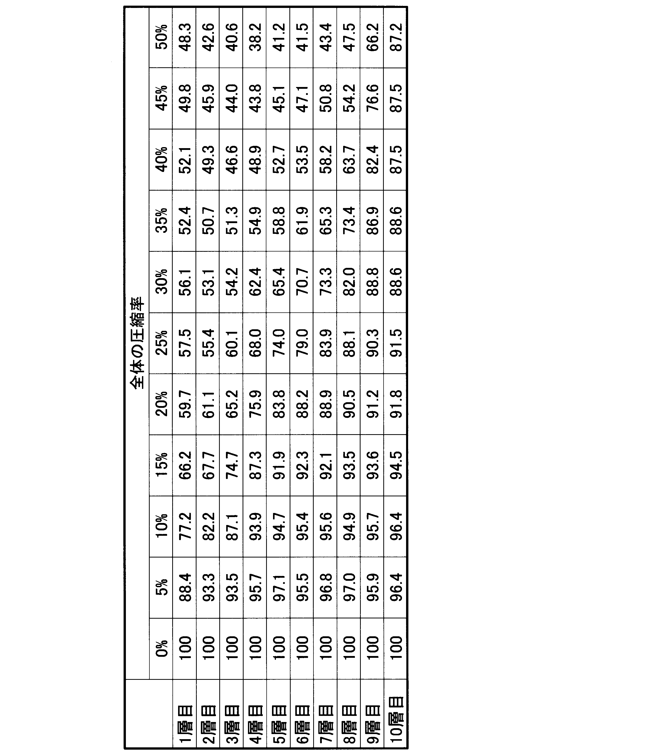
- the remaining thickness ratios of the respective layered portions L1 to L10 of the example are shown in FIG. 6 and Table 2, and the remaining thickness ratios of the respective layered portions L1 to L10 of the comparative example are shown in FIG.
- the layered portions L1 to L10 are counted as the first layer, the second layer,..., The tenth layer from the seating surface 1A side to the back surface 1B side along the vertical direction Y. .
- the first layer is the surface layer L1
- the tenth layer is the back surface layer L10
- the ninth layer is the back surface adjacent layer L9.
- the horizontal axis represents the compression ratio (%) of the entire evaluation sample S (sheet pad 1)
- the vertical axis represents the remaining thickness ratio (%) of each of the layered portions L1 to L10.
- Tables 2 and 3 show the same contents as those shown in FIGS. 6 and 7, that is, the layer portions L1 to L10 with respect to the compression ratio (%) of the entire evaluation sample S (sheet pad 1). The remaining thickness ratio (%) is shown in the table.
- the remaining thickness ratio of the surface layer L1 is 66.2%, It is the lowest among the layered portions L1 to L10.
- the remaining thickness ratio of the back surface layer L10 is 87.2%, which is the highest of the plurality of layered portions L1 to L10. ing.
- the remaining thickness ratio of the surface layer L1 is reduced while decreasing the rate of change.
- the graph line of the layer L1 is formed in a curved shape that protrudes downward.
- at least the second graph line is formed in a curved shape that protrudes downward.
- the remaining thickness ratio of the back surface adjacent layer L9 is decreased while increasing the rate of change.
- the graph line of the back surface adjacent layer L9 is formed in a curved shape that is convex upward.
- the graph line of at least the eighth layer is formed in a curved shape that is convex upward.
- the remaining thickness ratio of the surface layer L1 is 85.7%. It is higher than the remaining thickness ratios of the fourth to sixth layers. Further, in the comparative example, as the entire sheet pad 1 is greatly compressed in the vertical direction Y, the remaining thickness ratios of the respective layered portions L1 to L10 are lowered while maintaining the same rate of change. In the graph shown in FIG. 2, the graph lines of the respective layered portions L1 to L10 are formed linearly (straight).
- FIG. 9 is a conceptual diagram illustrating a method for measuring the evaluation sample S of the example and the comparative example with a microscope.
- a photograph obtained by enlarging the central portion of each of the layered portions L1 to L10 of the evaluation sample S with an optical microscope is acquired, and lines extending in the vertical and horizontal directions passing through the center of the photo are set as a vertical reference line V 0 and a horizontal reference line H 0 , respectively. Further, vertical and horizontal lines are set that are equally divided from the vertical reference line V 0 and the horizontal reference line H 0 at intervals of 2 mm.
- the vertical line has a vertical reference line V 0 and three vertical lines on both sides as a measurement target. That is, in the example of FIG. 9, the measurement objects are V ⁇ 3 , V ⁇ 2 , V ⁇ 1 , V 0 , V 1 , V 2 , and V 3 . Then, in a range of 6mm around the horizontal reference line H 0 in each of these vertical line, counted visually the number of intersections between the backbone and the vertical line of the foam cells, the average of the count values for each seven vertical lines This average value is assumed to be the longitudinal diameter Ry of the foam cell. For example, in the example of FIG.
- V 3 the foam cell skeletons represented by 1, 2, 3, 4, 5, 6, 7, and 8 are in the range of 6 mm centered on the horizontal reference line H 0.
- the horizontal reference line H 0 and the three horizontal lines on both sides thereof are set as measurement objects. That is, in the example of FIG.
- the measurement objects are H ⁇ 3 , H ⁇ 2 , H ⁇ 1 , H 0 , H 1 , H 2 , and H 3 .
- the number of intersections between the foam cell skeleton and the horizontal line is visually counted, and the average of the count values for each of the seven horizontal lines is obtained.
- This average value is assumed to be the transverse diameter Rx of the foam cell. For example, in the example of FIG.
- the aspect ratio was measured for each of the layered portions L1 to L10 of the evaluation sample S of the example and the comparative example, and the results shown in Table 4 were obtained. Furthermore, when this result is represented by a graph displaying the horizontal axis from the surface layer L1 to the back surface layer L10 and the vertical axis as the aspect ratio, a graph as shown in FIG. 10 is obtained.
- FIG. 10 is a graph comparing the aspect ratio of each layered portion between the example and the comparative example.
- the aspect ratio is uniformly reduced from the front surface layer L1 toward the back surface layer L10.
- the comparative example it can be seen that the aspect ratio falls within a certain range from the front surface layer L1 to the back surface layer L10 and does not change significantly.
- the aspect ratio is defined by Rx / Ry
- the aspect ratio is uniformly reduced from the front surface layer L1 toward the back surface layer L10. It can be said that the ratio of the diameter of the firing cell in the horizontal direction to the diameter of the firing cell increases as it goes to the placement surface along the vertical direction.
- the ratio of the diameter of the horizontal firing cell to the diameter of the vertical firing cell does not change uniformly as it goes to the placement surface along the vertical direction.
- the aspect ratio of the example is analyzed in more detail, the aspect ratio of the surface layer L1 is 1.44, and the aspect ratio of the back surface layer L10 is 1.34. Further, the aspect ratios of the layered portions L5 and L6 located at the center in the vertical direction are both 1.38.
- the sheet pad 1 in an unloaded state is equally divided into 5 layers instead of equally dividing into 10 layers in the longitudinal direction Y, and then the remaining thickness ratio of each layered portion is obtained.
- the result was as shown in FIG. Even in this case, when the entire sheet pad is compressed 15% in the vertical direction, the remaining thickness ratio of the surface layer (the first layer in the graph of FIG. 8) is the lowest among the plurality of layered portions. It has become. Further, when the entire sheet pad is compressed 50% in the vertical direction, the remaining thickness ratio of the back surface layer (the fifth layer in the graph of FIG.
- the graph shown in FIG. 8 is the highest among the plurality of layered portions. Further, as the entire sheet pad is greatly compressed in the vertical direction, the remaining thickness ratio of the surface layer is lowered while decreasing the rate of change. In the graph shown in FIG. 8, the surface layer (first layer) The graph line is formed in a curved shape protruding downward. Further, in the example, as the entire sheet pad is greatly compressed in the vertical direction, the remaining thickness ratio of the back surface adjacent layer (the fourth layer in the graph of FIG. 8) is low while increasing the rate of change, In the graph shown in FIG. 8, the graph line of the back surface adjacent layer is formed in a curved shape that is convex upward.
- the seat pad 1 is applied as a flexible polyurethane foam molded article, but the present invention is not limited to this, and in addition to a seat pad for a vehicle such as an automobile, an indoor chair, bedding, etc. It is possible to target products of various uses such as cushioning materials for flooring and cushioning materials for flooring of houses. Further, the flexible polyurethane foam molded product is not limited to a product on which a person is seated, and may be a product on which luggage or the like is placed.
- the flexible polyurethane foam molded article is not limited to a configuration in which the mounting surface extends in the horizontal direction perpendicular to the vertical direction as in the seating surface 1A of the present embodiment, but various applications such as a configuration in which the mounting surface extends in the vertical direction, for example. It is possible to target products.
- the remaining thickness ratio of the back surface adjacent layer L9 is decreased while increasing the rate of change, but the present invention is not limited to this.
- the remaining thickness ratio in at least one layer located on the back surface 1B side from the center in the longitudinal direction Y of the sheet pad 1 increases the rate of change as described above.
- the remaining thickness ratio in a layer different from the back surface adjacent layer L9 may be lowered while increasing the rate of change as described above.
- the remaining thickness ratios in the plurality of layers of the layered portions L6 to L10 of the sixth layer to the tenth layer may be lowered while increasing the rate of change as described above.
- the center of the vertical direction Y of the pad 1 for sheets is contained in one layer (henceforth a "center layer") of a some layered part, at least 1 located in the back surface 1B side rather than a center layer.
- the soft polyurethane foam molded product which can suppress a feeling of wobble while suppressing impairing a seating feeling, and the pad for sheets can be provided.
Landscapes
- Engineering & Computer Science (AREA)
- Aviation & Aerospace Engineering (AREA)
- Transportation (AREA)
- Mechanical Engineering (AREA)
- Manufacturing & Machinery (AREA)
- Polyurethanes Or Polyureas (AREA)
- Mattresses And Other Support Structures For Chairs And Beds (AREA)
Abstract
Description
本願は、2015年11月11日に日本国に出願された特願2015-221442号に基づき優先権を主張し、その内容をここに援用する。
金型3は、下型31と上型32とを備える箱形状に形成され、その内部空間が、シート用パッド1を形成するキャビティCとなっている。上型32は、下型31の上端開口を塞ぐ蓋材であって、外周部に上下に貫くエア抜き孔33が形成されている。
ここで、所定の負荷が付与された状態(以下、「負荷付与状態」という。)における各層状部分L1~L10の残存厚さ率とは、当該層状部分L1~L10の無負荷状態での厚さ(T0)に対する負荷付与状態での厚さ(T)の割合(T/T0)を意味する。
さらに、シート用パッド1全体が縦方向Yに大きく圧縮するに従い、複数の層状部分L1~L10のうち、シート用パッド1の縦方向Yの中央よりも裏面1B側に位置する少なくとも1層における残存厚さ率が、変化の割合を増大させつつ低くなる。本実施形態では、シート用パッド1の縦方向Yの中央が、着座面1A側から5層目の層状部分L5と6層目の層状部分L6との境界上に位置している。そして、シート用パッド1の縦方向Yの中央よりも裏面1B側に位置する複数の層状部分L6~L10のうち、裏面層L10に隣接する層状部分L9、つまり裏面1B側から2番目の層状部分L9(以下、「裏面隣接層L9」という。)における残存厚さ率が、前述のように変化の割合を増大させつつ低くなる。裏面隣接層L9は、付与される負荷が小さい段階では圧縮し難く、付与される負荷が大きい段階では圧縮し易い。
(B) 架橋剤成分として発泡原液中に含まれる化合物の全体(架橋剤の総体)におけるエチレンオキシド基/プロピレンオキシド基(モル比)は100以上である。
(C) ポリイソシアネートとして、ジフェニルメタンジイソシアネート(MDI)をイソシアネート当量で70以上含有する。
前記発泡原液を構成するポリオール成分として、重量平均分子量Mwが3000~12000であり、且つ官能基数(ヒドロキシル基の数)が3~4であるポリエーテルポリオールを含有する。上記ポリエーテルポリオールとしては、反応性が良好であることから、アルキレンオキシドの開環重合により得られるポリエーテルポリオールが好ましい。
アルキレンオキシドとしては、プロピレンオキシド(PO)、エチレンオキシド(EO)等が挙げられる。ポリエーテルポリオールの材料として使用されるアルキレンオキシドは1種類であってもよいし、2種類以上であってもよい。
前記発泡原液を構成するポリイソシアネート成分として、ジフェニルメタンジイソシアネートをイソシアネート当量で70以上含有する。
前記発泡原液において、1種類のMDIが単独で含有されてもよいし、2種類以上のMDIが含有されてもよい。
前記発泡原液が発泡成形されてなる軟質ポリウレタンフォームが所望の物性を有するために、前記発泡原液を構成する架橋剤成分として、前記ポリイソシアネート成分に対する反応性が水よりも高い架橋剤が、主成分として含まれることが好ましい。通常、グリセリン、エチレンオキシド基を有する架橋剤(EO系架橋剤)、水、プロピレンオキシド基を有する架橋剤(PO系架橋剤)の順で、前記ポリイソシアネート成分に対する反応性が低下する。これに基づいて、前記発泡原液に架橋剤として含有される1種又は2種以上の化合物の全体が有するEO基とPO基のモル比(EO基のモル数/PO基のモル数)は100以上であることが好ましく、105以上であることがより好ましく、110以上であることがさらに好ましい。このモル比は高い程好ましい。つまり、前記発泡原液において、PO基を有する架橋剤が実質的には含有されないことが好ましい。
前記発泡原液を構成する発泡剤成分としては、水を用いることが好ましい。水はポリイソシアネートと反応して炭酸ガスを発生するため、発泡剤として機能する。
前記発泡原液中の水の含有量としては、ポリオール成分100質量部に対して、1~7質量部であることが好ましく、2~5質量部であることがより好ましい。上記範囲であると、所望の物性を有する軟質ポリウレタンフォームが容易に得られる。また、得られた軟質ポリウレタンフォームの熱圧縮残留歪み特性が劣化することを防止できる。
前記発泡原液を構成する触媒成分としては、ポリウレタンフォームの分野で使用される公知の触媒が挙げられる。公知の触媒としては、アミン系触媒、スズ触媒が挙げられる。
好適な樹脂化触媒は、ポリイソシアネートとポリオールの反応を特に促進する第三級アミン触媒であり、特に限定しないが、例えば、トリエチレンジアミン、1,8-ジアザビシクロ[5.4.0]ウンデセン-7、及び1-メチルイミダゾール、1、2-ジメチルイミダゾール、1-イソブチル-2-メチルイミダゾール等のイミダゾール類、1,1’-((3-(ジメチルアミノ)プロピル)イミノ)ビス(2-プロパノール)が挙げられる。また好適な泡化触媒は、イソシアネ-トと水の反応を特に促進し、炭酸ガスを有効に発生させる第三級アミン触媒であり、一般的にフォームの流動性、寸法安定性改良に使用される。泡化触媒としては特に限定しないが、ビス(2-ジメチルアミノエチル)エーテル、N,N,N′,N″,N″-ペンタメチルジエチレントリアミン、及びN,N,N′,N″,N''',N'''-ヘキサメチルトリエチレンテトラミン等が挙げられる。
前記発泡原液に含有される、樹脂化触媒:泡化触媒の質量比は、100:0~100:100が好ましく、100:0~100:50がより好ましく、100:0~100:20がさらに好ましい。
ここで、ゲル化触媒定数は、ポリオール類とポリイソシアネート類との樹脂化反応の速度を決定する定数であり、その値が大きくなると発泡体の架橋密度が高くなって発泡体の機械的物性が良好になる。具体的には、トリレンジイソシアネートとジエチレングリコールとのゲル化反応の反応定数が用いられる。一方、泡化触媒定数は、ポリイソシアネート類と水との泡化反応の速度を決定する定数であり、その値が大きくなると発泡体のセルの連通性が高められる。具体的には、トリレンジイソシアネートと水との泡化反応の反応定数が用いられる。上記2つの触媒定数の比は、両方の触媒のバランスを表す。
好適なアミン系触媒の例を、前記樹脂化触媒の具体例も含めて以下に例示する。
前記発泡原液には、整泡剤が含まれてもよい。整泡剤としては、ポリウレタンフォームの分野で使用される公知の整泡剤が適用可能であり、例えば、シリコーン系整泡剤、アニオン系整泡剤、カチオン系整泡剤が挙げられる。これらの整泡剤には、分子鎖末端に水酸基を有する整泡剤が含まれる。
前記発泡原液には、必要に応じて各種添加剤を配合することができる。例えば、顔料等の着色剤、鎖延長剤、炭酸カルシウム等の充填材、難燃剤、酸化防止剤、紫外線吸収剤、光安定剤、カーボンブラック等の導電性物質、抗菌剤などを配合することができる。各種添加剤の配合量は、用途や目的に応じて適宜調整される。
前記発泡原液の調製方法は、特に限定されず、例えば、ポリイソシアネート成分を除いた、残りの各成分からなる混合物(以下、「ポリオール混合物」と略記することがある。)を調製し、その後、ポリイソシアネート成分と混合して、発泡原液を得る調製方法が挙げられる。
その後、軟質ポリウレタンフォームを発泡成形する工程において、前記ポリオール混合物とポリイソシアネート成分とを混合し、発泡原液を調製することが好ましい。
表1に示す配合のポリオール成分配合液と、イソシアネート成分とを混合して調製したウレタン配合原液を金型3のキャビティCに注入して発泡成形することにより、図3および図4に示す偏平直方体状のシート用パッド1のテストピース(以下、単に「シート用パッド1」という。)を製造し、前述した残存厚さ率を測定した。このシート用パッド1の着座面1Aは、一辺の長さ400mmの正方形であり、シート用パッド1全体の厚さは、100mmである。

「ポリエーテルポリオールA1-2」は、EO/POモル比13/87、重量平均分子量7000、官能基数3である。
「ポリマーポリオールA2-1」は、固形分33%、水酸基価23mgKOH/g、重量平均分子量5400、3.2官能のポリマーポリオール(三洋化成工業株式会社製、商品名:KC855)である。
「架橋剤C-2」は、EO/POモル比100/0、重量平均分子量400、官能基数4である。
「架橋剤C-3」は、グリセリンである。
「触媒D-2」は、市販の樹脂化触媒であり、トリエチレンジアミンである。
「触媒D-3」は、市販の泡化触媒であり、(2-ジメチルアミノエチル)エーテルである。
「触媒D-4」は、市販のジエタノールアミンであり、樹脂化と泡化の両方を触媒する。
「整泡剤E-2」は、エボニック社製の高活性型のシリコーン系整泡剤(商品名:B8742)である。
「発泡剤F-1」は、水である。
「ポリイソシアネート(B-2)」は、市販のポリイソシアネートであり、TDI/MDI=80/20(質量比)で混合されたTDI系イソシアネートである。
具体的には、評価サンプルSは、シート用パッド1の一部分であるサンプル部分S1を縦方向Yに抜き取ることで採取した。評価サンプルSの形状は、一辺の長さが100mmの立方体とした。図4に示すように、サンプル部分S1における外周縁を構成する各辺部は、シート用パッド1における外周縁を構成する各辺部と平行になっていて、これらの各辺部同士は、100mm以上離間させた。
まず、図5に示すように、無負荷状態の評価サンプルSに、各層状部分L1~L10を区画する区画線を引くとともに、評価サンプルSを上下一対の加圧板P間に挟みこむ。加圧板Pは、平面視において評価サンプルSの全体を覆うように形成されていて、評価サンプルSを全面圧縮する。そして、例えば所望の圧力で加圧板Pを加圧可能な試験機を用いて一対の加圧板P間の間隔を狭め、評価サンプルSの縦方向Yの圧縮率((圧縮により減少した厚さ)/(無負荷状態での厚さ))を徐々に大きくしていき、圧縮率0%~50%に至るまで、5%刻みで各層状部分L1~L10の厚さ(隣り合う区画線同士の縦方向Yの間隔)を計測し、各層状部分L1~L10の残存厚さ率を算出する。なお図5では、評価サンプルSを全面圧縮した後における各層状部分L1~L10の厚さを、模式的に互いに同等として表している。
なお、図6、図7に示すグラフでは、横軸が評価サンプルS(シート用パッド1)全体の圧縮率(%)であり、縦軸が各層状部分L1~L10の残存厚さ率(%)となっている。また、表2、表3は、図6、図7に図示されたのと同様の内容、即ち、評価サンプルS(シート用パッド1)全体の圧縮率(%)に対する各層状部分L1~L10の残存厚さ率(%)を表に示している。
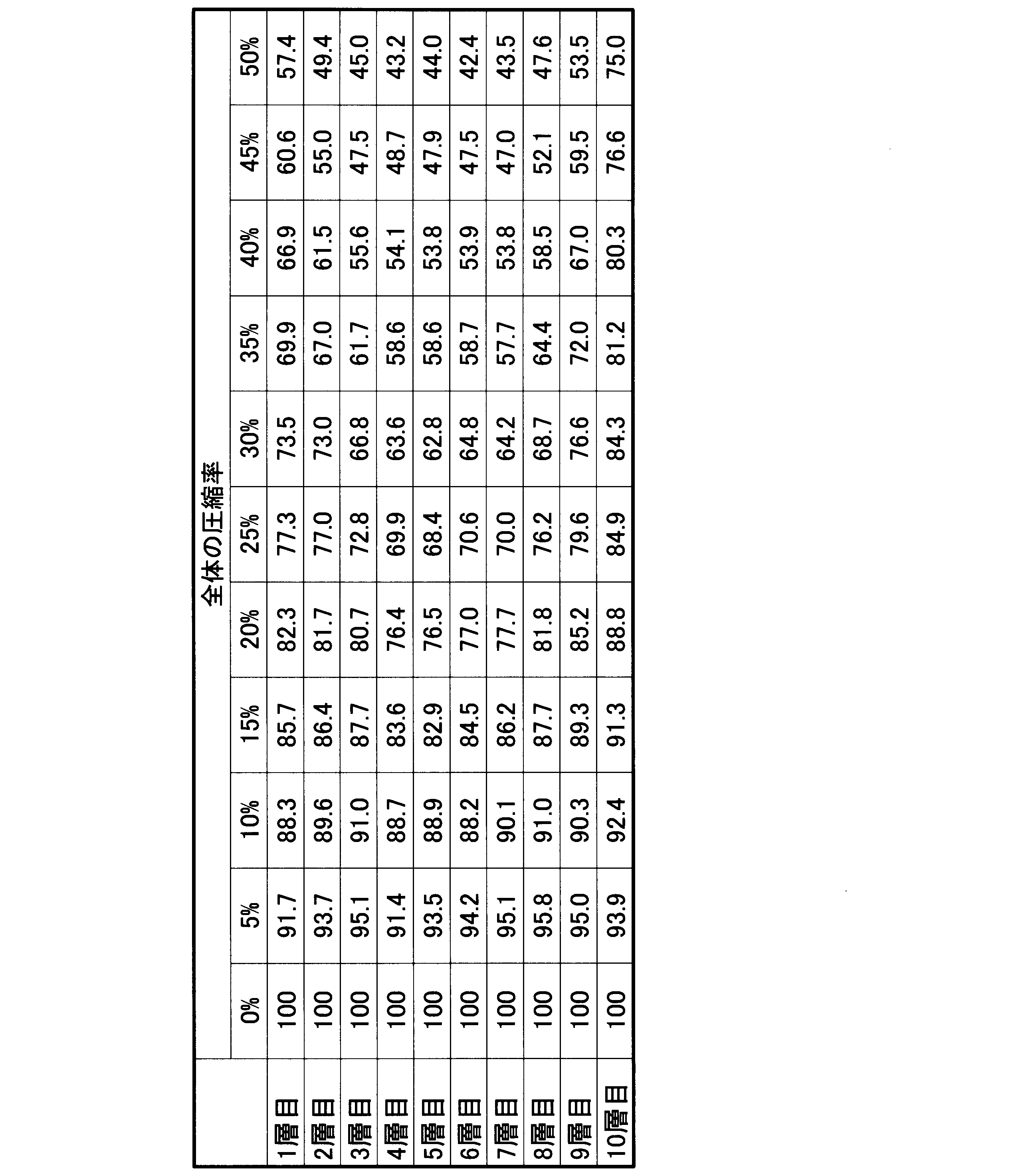
また比較例では、シート用パッド1全体が縦方向Yに大きく圧縮するに従い、各層状部分L1~L10の残存厚さ率が、変化の割合が同等に維持されたまま低くなっており、図7に示すグラフにおいて、各層状部分L1~L10のグラフ線が、線形(直線状)に形成されている。
評価サンプルSの各層状部分L1~L10の中央部分を光学顕微鏡で拡大した写真を取得し、写真の中心を通る縦横方向に延びるラインをそれぞれ縦基準線V0、横基準線H0とする。さらに縦基準線V0及び横基準線H0のそれぞれから2mm間隔で等分割した縦横ラインを設定する。ここで、縦横ラインには、上記の縦基準線V0及び横基準線H0も含める。縦ラインは、縦ラインのうち、縦基準線V0とその両側の3本の縦ラインを測定対象とする。即ち、図9の例では、測定対象は、V-3、V-2、V-1、V0、V1、V2、V3である。そして、これら縦ライン毎に横基準線H0を中心とした6mmの範囲において、発泡セルの骨格と縦ラインとの交点の数を目視によりカウントし、7本の縦ライン毎のカウント値の平均を求め、この平均値を発泡セルの縦方向の直径Ryと仮定する。例えば、図9の例では、V3において、横基準線H0を中心とした6mmの範囲において、1,2,3,4,5,6,7,8で表示される発泡セルの骨格と縦ラインとの交点を8個のカウントできる。これをV-3、V-2、V-1、V0、V1、V2、V3のすべてについてカウントし、その平均を算出し、これを発泡セルの縦方向の直径Ryと仮定する。
また、横方向についても同様に、横ラインのうち、横基準線H0とその両側の3本の横ラインを測定対象とする。即ち、図9の例では、測定対象は、H-3、H-2,H-1、H0、H1、H2、H3である。これら横ライン毎に縦基準線V0を中心とした10mmの範囲において、発泡セルの骨格と横ラインとの交点の数を目視によりカウントし、7本の横ライン毎のカウント値の平均を求め、この平均値を発泡セルの横方向の直径Rxと仮定する。例えば、図9の例では、H3において、縦基準線V0を中心とした10mmの範囲において、a,b,c,d,e,f,g,hで表示される発泡セルの骨格と縦ラインとの交点を8個のカウントできる。これをH-3、H-2,H-1、H0、H1、H2、H3のすべてについてカウントし、その平均を算出し、これを発泡セルの横方向の直径Rxと仮定する。
その後、発泡セルの縦横寸法をRx/Ry(平均値の逆数)により算出し、アスペクト比を測定することができる。
なお、前述の評価サンプルS(立方体)の寸法、縦横ラインの間隔、分割数、カウント範囲(長さ)などは、適宜、変更可能である。

実施例のアスペクト比をさらに詳細に分析すると、表面層L1のアスペクト比が1.44であり、裏面層L10のアスペクト比が1.34である。また、縦方向の中央に位置する層状部分L5とL6のアスペクト比が共に1.38である。
なお実施例において、無負荷状態のシート用パッド1を、縦方向Yに10層に等分するのに代えて5層に等分した上で、各層状部分の残存厚さ率を求めると、図8に示すような結果になった。
この場合であっても、シート用パッド全体が縦方向に15%圧縮されたときに、表面層(図8のグラフにおける1層目)の残存厚さ率が、複数の層状部分のうちで最低となっている。また、シート用パッド全体が縦方向に50%圧縮されたときに、裏面層(図8のグラフにおける5層目)の残存厚さ率が、複数の層状部分のうちで最高となっている。また、シート用パッド全体が縦方向に大きく圧縮するに従い、表面層の残存厚さ率が、変化の割合を減少させつつ低くなっており、図8に示すグラフにおいて、表面層(1層目)のグラフ線が、下に凸となる曲線状に形成されている。さらに実施例では、シート用パッド全体が縦方向に大きく圧縮するに従い、裏面隣接層(図8のグラフにおける4層目)の残存厚さ率が、変化の割合を増大させつつ低くなっており、図8に示すグラフにおいて、裏面隣接層のグラフ線が、上に凸となる曲線状に形成されている。
また、軟質ポリウレタンフォーム成形品は、人が着座する製品に限らず、荷物等を載置する製品であっても良い。
また、軟質ポリウレタンフォーム成形品は、載置面が、本実施の形態の着座面1Aのように鉛直方向に直交する水平方向に延びる構成に限らず、例えば鉛直方向に延びる構成等、様々な用途の製品を対象とすることが可能である。
なお、複数の層状部分のうちの1つの層(以下、「中央層」という。)にシート用パッド1の縦方向Yの中央が含まれる場合、中央層よりも裏面1B側に位置する少なくとも1層における残存厚さ率が、前述のように変化の割合を増大させつつ低くなる構成を採用することで、同様の作用効果を奏功させることができる。
1A 着座面(載置面)
1B 裏面(反載置面)
L1~L10 層状部分
Y 縦方向
Claims (5)
- 載置面を有し、発泡原液が発泡し成形されることで得られる軟質ポリウレタンフォーム成形品であって、
前記載置面に直交する縦方向に層をなす複数の層状部分を有し、
前記複数の層状部分のうち、前記縦方向に沿って最も前記載置面側に位置する表面層では、前記軟質ポリウレタンフォーム成形品全体が前記縦方向に15%圧縮されたときに、前記縦方向の残存厚さ率が、前記複数の層状部分のうちで最低となり、
前記複数の層状部分のうち、前記縦方向に沿って最も反載置面側に位置する裏面層では、前記軟質ポリウレタンフォーム成形品全体が前記縦方向に50%圧縮されたときに、前記縦方向の残存厚さ率が、前記複数の層状部分のうちで最高となる軟質ポリウレタンフォーム成形品。 - 前記軟質ポリウレタンフォーム成形品全体が前記縦方向に大きく圧縮するに従い、前記表面層の残存厚さ率が、変化の割合を減少させつつ低くなる請求項1に記載の軟質ポリウレタンフォーム成形品。
- 前記軟質ポリウレタンフォーム成形品全体が前記縦方向に大きく圧縮するに従い、前記複数の層状部分のうち、前記軟質ポリウレタンフォーム成形品の前記縦方向の中央よりも反載置面側に位置する少なくとも1層における残存厚さ率が、変化の割合を増大させつつ低くなる請求項1または2に記載の軟質ポリウレタンフォーム成形品。
- 車両に取り付けられ着座部として用いられるシート用パッドであって、
請求項1または2に記載の前記軟質ポリウレタンフォーム成形品であるシート用パッド。 - 車両に取り付けられ着座部として用いられるシート用パッドであって、
請求項3に記載の前記軟質ポリウレタンフォーム成形品であるシート用パッド。
Priority Applications (4)
| Application Number | Priority Date | Filing Date | Title |
|---|---|---|---|
| JP2017550383A JP6744871B2 (ja) | 2015-11-11 | 2016-11-10 | 軟質ポリウレタンフォーム成形品、およびシート用パッド |
| EP16864302.1A EP3375329A4 (en) | 2015-11-11 | 2016-11-10 | Flexible polyurethane foam molded article and pad for sheets |
| CN201680065598.XA CN108348075B (zh) | 2015-11-11 | 2016-11-10 | 软质聚氨酯发泡成形品和座垫 |
| US15/770,057 US10549666B2 (en) | 2015-11-11 | 2016-11-10 | Flexible polyurethane foam molded article, and seat pad |
Applications Claiming Priority (2)
| Application Number | Priority Date | Filing Date | Title |
|---|---|---|---|
| JP2015-221442 | 2015-11-11 | ||
| JP2015221442 | 2015-11-11 |
Publications (1)
| Publication Number | Publication Date |
|---|---|
| WO2017082341A1 true WO2017082341A1 (ja) | 2017-05-18 |
Family
ID=58696159
Family Applications (1)
| Application Number | Title | Priority Date | Filing Date |
|---|---|---|---|
| PCT/JP2016/083360 Ceased WO2017082341A1 (ja) | 2015-11-11 | 2016-11-10 | 軟質ポリウレタンフォーム成形品、およびシート用パッド |
Country Status (5)
| Country | Link |
|---|---|
| US (1) | US10549666B2 (ja) |
| EP (1) | EP3375329A4 (ja) |
| JP (1) | JP6744871B2 (ja) |
| CN (1) | CN108348075B (ja) |
| WO (1) | WO2017082341A1 (ja) |
Cited By (2)
| Publication number | Priority date | Publication date | Assignee | Title |
|---|---|---|---|---|
| WO2020004123A1 (ja) * | 2018-06-26 | 2020-01-02 | 株式会社ブリヂストン | 低臭気ポリウレタンフォーム製造用ポリオール組成物 |
| US10870377B2 (en) | 2014-06-12 | 2020-12-22 | Bridgestone Corporation | Soft polyurethane foam molded article and seat pad |
Families Citing this family (1)
| Publication number | Priority date | Publication date | Assignee | Title |
|---|---|---|---|---|
| JP7039275B2 (ja) * | 2017-12-14 | 2022-03-22 | 株式会社ブリヂストン | 車両用シート、及び、パッド振動特性の調整方法 |
Citations (2)
| Publication number | Priority date | Publication date | Assignee | Title |
|---|---|---|---|---|
| JP2003211612A (ja) * | 2002-01-23 | 2003-07-29 | Okamoto Ind Inc | ウレタン樹脂系表皮材 |
| JP2011189121A (ja) * | 2010-02-19 | 2011-09-29 | Inoac Corp | クッションパッド及びその製造方法 |
Family Cites Families (11)
| Publication number | Priority date | Publication date | Assignee | Title |
|---|---|---|---|---|
| JP4306818B2 (ja) | 1997-07-14 | 2009-08-05 | トヨタ自動車株式会社 | 軟質ポリウレタンフォーム |
| JP3066491B2 (ja) * | 1998-11-18 | 2000-07-17 | 工業技術院長 | クッション材の沈み量算出方法 |
| US6863953B2 (en) | 2001-09-13 | 2005-03-08 | Okamoto Industries, Inc. | Surface material of urethane resin and a method for preparation thereof |
| FR2836470B1 (fr) | 2002-02-25 | 2004-07-09 | J S O | Matelassure en mousse de melanine et ses applications |
| JP3948989B2 (ja) | 2002-03-28 | 2007-07-25 | 株式会社イノアックコーポレーション | クッション体 |
| CN101061155B (zh) * | 2004-11-24 | 2010-07-21 | 旭硝子株式会社 | 软质聚氨酯泡沫塑料、其制造方法以及汽车用座垫 |
| US7708342B2 (en) * | 2005-08-31 | 2010-05-04 | Leach Jamie S | Non-slip body-conforming booster cushion seat |
| FR2897023B1 (fr) | 2006-02-06 | 2008-04-18 | Faurecia Sieges Automobile | Coussin d'element de siege de vehicule automobile et procede de fabrication d'un tel coussin |
| JP4843476B2 (ja) | 2006-12-15 | 2011-12-21 | 日本発條株式会社 | パッド、シート、クッション及びそれらの製造方法 |
| CN104340099B (zh) * | 2013-07-31 | 2017-06-06 | 东洋橡胶工业株式会社 | 座椅缓冲垫 |
| US10870377B2 (en) | 2014-06-12 | 2020-12-22 | Bridgestone Corporation | Soft polyurethane foam molded article and seat pad |
-
2016
- 2016-11-10 CN CN201680065598.XA patent/CN108348075B/zh active Active
- 2016-11-10 JP JP2017550383A patent/JP6744871B2/ja active Active
- 2016-11-10 US US15/770,057 patent/US10549666B2/en active Active
- 2016-11-10 WO PCT/JP2016/083360 patent/WO2017082341A1/ja not_active Ceased
- 2016-11-10 EP EP16864302.1A patent/EP3375329A4/en not_active Withdrawn
Patent Citations (2)
| Publication number | Priority date | Publication date | Assignee | Title |
|---|---|---|---|---|
| JP2003211612A (ja) * | 2002-01-23 | 2003-07-29 | Okamoto Ind Inc | ウレタン樹脂系表皮材 |
| JP2011189121A (ja) * | 2010-02-19 | 2011-09-29 | Inoac Corp | クッションパッド及びその製造方法 |
Non-Patent Citations (1)
| Title |
|---|
| See also references of EP3375329A4 * |
Cited By (2)
| Publication number | Priority date | Publication date | Assignee | Title |
|---|---|---|---|---|
| US10870377B2 (en) | 2014-06-12 | 2020-12-22 | Bridgestone Corporation | Soft polyurethane foam molded article and seat pad |
| WO2020004123A1 (ja) * | 2018-06-26 | 2020-01-02 | 株式会社ブリヂストン | 低臭気ポリウレタンフォーム製造用ポリオール組成物 |
Also Published As
| Publication number | Publication date |
|---|---|
| CN108348075B (zh) | 2021-03-23 |
| EP3375329A1 (en) | 2018-09-19 |
| JPWO2017082341A1 (ja) | 2018-08-30 |
| CN108348075A (zh) | 2018-07-31 |
| US10549666B2 (en) | 2020-02-04 |
| US20180312089A1 (en) | 2018-11-01 |
| JP6744871B2 (ja) | 2020-08-19 |
| EP3375329A4 (en) | 2018-09-19 |
Similar Documents
| Publication | Publication Date | Title |
|---|---|---|
| JP6580564B2 (ja) | 軟質ポリウレタンフォーム成形品、およびシート用パッド | |
| JP6484622B2 (ja) | 軟質ポリウレタンフォーム、及びシート用パッド | |
| JP2017110113A (ja) | 軟質ポリウレタンフォーム、及びシート用パッド | |
| JPWO2017104605A1 (ja) | シート用パッド | |
| JP6989522B2 (ja) | シート用パッド | |
| JP6744871B2 (ja) | 軟質ポリウレタンフォーム成形品、およびシート用パッド | |
| WO2017104600A1 (ja) | 軟質ポリウレタンフォーム、及びシート用パッド | |
| JP6703991B2 (ja) | 軟質ポリウレタンフォーム成形品、およびシート用パッド | |
| JP6484623B2 (ja) | 軟質ポリウレタンフォーム、及びシート用パッド | |
| JP2017070628A (ja) | シートパッド、及びシートパッドの製造方法 | |
| WO2017104649A1 (ja) | 軟質ポリウレタンフォーム、及びシート用パッド | |
| JP2013173813A (ja) | シート用パッド | |
| WO2017104608A1 (ja) | 軟質ポリウレタンフォーム、及びシート用パッド |
Legal Events
| Date | Code | Title | Description |
|---|---|---|---|
| 121 | Ep: the epo has been informed by wipo that ep was designated in this application |
Ref document number: 16864302 Country of ref document: EP Kind code of ref document: A1 |
|
| ENP | Entry into the national phase |
Ref document number: 2017550383 Country of ref document: JP Kind code of ref document: A |
|
| WWE | Wipo information: entry into national phase |
Ref document number: 15770057 Country of ref document: US |
|
| NENP | Non-entry into the national phase |
Ref country code: DE |
|
| WWE | Wipo information: entry into national phase |
Ref document number: 2016864302 Country of ref document: EP |