WO2017082362A1 - タイヤ管理方法及びタイヤ管理装置 - Google Patents
タイヤ管理方法及びタイヤ管理装置 Download PDFInfo
- Publication number
- WO2017082362A1 WO2017082362A1 PCT/JP2016/083413 JP2016083413W WO2017082362A1 WO 2017082362 A1 WO2017082362 A1 WO 2017082362A1 JP 2016083413 W JP2016083413 W JP 2016083413W WO 2017082362 A1 WO2017082362 A1 WO 2017082362A1
- Authority
- WO
- WIPO (PCT)
- Prior art keywords
- tire
- temperature
- value
- predetermined time
- unit
- Prior art date
- Legal status (The legal status is an assumption and is not a legal conclusion. Google has not performed a legal analysis and makes no representation as to the accuracy of the status listed.)
- Ceased
Links
Images

Classifications
-
- B—PERFORMING OPERATIONS; TRANSPORTING
- B60—VEHICLES IN GENERAL
- B60C—VEHICLE TYRES; TYRE INFLATION; TYRE CHANGING; CONNECTING VALVES TO INFLATABLE ELASTIC BODIES IN GENERAL; DEVICES OR ARRANGEMENTS RELATED TO TYRES
- B60C11/00—Tyre tread bands; Tread patterns; Anti-skid inserts
- B60C11/24—Wear-indicating arrangements
- B60C11/246—Tread wear monitoring systems
-
- B—PERFORMING OPERATIONS; TRANSPORTING
- B60—VEHICLES IN GENERAL
- B60C—VEHICLE TYRES; TYRE INFLATION; TYRE CHANGING; CONNECTING VALVES TO INFLATABLE ELASTIC BODIES IN GENERAL; DEVICES OR ARRANGEMENTS RELATED TO TYRES
- B60C23/00—Devices for measuring, signalling, controlling, or distributing tyre pressure or temperature, specially adapted for mounting on vehicles; Arrangement of tyre inflating devices on vehicles, e.g. of pumps or of tanks; Tyre cooling arrangements
- B60C23/20—Devices for measuring or signalling tyre temperature only
-
- B—PERFORMING OPERATIONS; TRANSPORTING
- B60—VEHICLES IN GENERAL
- B60C—VEHICLE TYRES; TYRE INFLATION; TYRE CHANGING; CONNECTING VALVES TO INFLATABLE ELASTIC BODIES IN GENERAL; DEVICES OR ARRANGEMENTS RELATED TO TYRES
- B60C11/00—Tyre tread bands; Tread patterns; Anti-skid inserts
- B60C11/24—Wear-indicating arrangements
-
- B—PERFORMING OPERATIONS; TRANSPORTING
- B60—VEHICLES IN GENERAL
- B60C—VEHICLE TYRES; TYRE INFLATION; TYRE CHANGING; CONNECTING VALVES TO INFLATABLE ELASTIC BODIES IN GENERAL; DEVICES OR ARRANGEMENTS RELATED TO TYRES
- B60C19/00—Tyre parts or constructions not otherwise provided for
-
- G—PHYSICS
- G01—MEASURING; TESTING
- G01M—TESTING STATIC OR DYNAMIC BALANCE OF MACHINES OR STRUCTURES; TESTING OF STRUCTURES OR APPARATUS, NOT OTHERWISE PROVIDED FOR
- G01M17/00—Testing of vehicles
- G01M17/007—Wheeled or endless-tracked vehicles
- G01M17/02—Tyres
-
- G—PHYSICS
- G01—MEASURING; TESTING
- G01N—INVESTIGATING OR ANALYSING MATERIALS BY DETERMINING THEIR CHEMICAL OR PHYSICAL PROPERTIES
- G01N17/00—Investigating resistance of materials to the weather, to corrosion, or to light
-
- B—PERFORMING OPERATIONS; TRANSPORTING
- B60—VEHICLES IN GENERAL
- B60C—VEHICLE TYRES; TYRE INFLATION; TYRE CHANGING; CONNECTING VALVES TO INFLATABLE ELASTIC BODIES IN GENERAL; DEVICES OR ARRANGEMENTS RELATED TO TYRES
- B60C19/00—Tyre parts or constructions not otherwise provided for
- B60C2019/004—Tyre sensors other than for detecting tyre pressure
-
- B—PERFORMING OPERATIONS; TRANSPORTING
- B60—VEHICLES IN GENERAL
- B60C—VEHICLE TYRES; TYRE INFLATION; TYRE CHANGING; CONNECTING VALVES TO INFLATABLE ELASTIC BODIES IN GENERAL; DEVICES OR ARRANGEMENTS RELATED TO TYRES
- B60C19/00—Tyre parts or constructions not otherwise provided for
- B60C2019/006—Warning devices, e.g. devices generating noise due to flat or worn tyres
- B60C2019/007—Warning devices, e.g. devices generating noise due to flat or worn tyres triggered by sensors
Definitions
- the present invention relates to a tire management method and a tire management device.
- a tire pressure monitoring system that issues an alarm when the air pressure (tire internal pressure) filled in the pneumatic tire decreases beyond an allowable range
- TPMS tire pressure monitoring system
- the temperature inside the tire is often measured together with the tire internal pressure. Therefore, it would be convenient if the temperature inside the tire could be used to accurately know the situation of the pneumatic tire, but there was no such technique in the past.
- An object of the present invention is to provide a tire management method and a tire management device capable of easily grasping the usage status of a pneumatic tire based on the temperature inside the tire.
- a tire management method includes a step of detecting a temperature at a predetermined time in a tire air chamber of a pneumatic tire of a vehicle by a temperature detection unit, By the conversion unit, the detected temperature in the tire air chamber is changed to a first multiplication value obtained by multiplying the load and speed in the tire or a second multiplication value obtained by multiplying the square of the load in the tire and the speed. Converting, and And a step of calculating an integrated value obtained by integrating the first multiplied value or the second multiplied value for a predetermined time by an integrating unit.
- a tire management device includes a temperature detection unit that detects a temperature at a predetermined time in a tire air chamber of a pneumatic tire of a vehicle, A first multiplied value obtained by multiplying the temperature in the tire air chamber detected by the temperature detection unit every predetermined time by a load and a speed in the tire or a second multiplied value obtained by multiplying the square of the load in the tire and the speed.
- a conversion unit for converting to And an integration unit that calculates an integrated value obtained by integrating the first multiplied value or the second multiplied value for a predetermined time.
- the present invention it is possible to provide a tire management method and a tire management device capable of easily grasping the usage status of a pneumatic tire based on the temperature inside the tire.
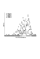
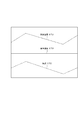
- FIG. 6 is a diagram showing a relationship between an average daily traveling distance and a failure frequency for each of the failed parts 1 to 4; It is a figure which shows detected temperature, reference temperature, and air temperature.
- FIG. 1 is a block diagram schematically showing a configuration of a tire management device according to an embodiment of the present invention.
- the tire management device 10 of the present embodiment includes a temperature detection unit 11, a calculation unit 12, and a determination unit 13, and based on information from the calculation unit 12, a pneumatic tire.
- the pneumatic tire is an ultra-large pneumatic tire (OR tire) used for heavy-duty pneumatic tires (hereinafter also simply referred to as tires) construction and mining vehicles.
- OR tire ultra-large pneumatic tire
- a vehicle or the like to which a tire managed by the tire management device 10 is attached has a six-wheel specification with two front wheels and four rear wheels. / 3 is used on the front wheel (front), and then the remaining 2/3 is used on the rear wheel (rear).
- the temperature detection unit 11 includes, for example, a temperature detection sensor 14 that detects the temperature in the tire air chamber, and a control unit (ECU) 15 that is mounted on the vehicle.
- ECU control unit
- the temperature detection sensor 14 is a tire pressure monitoring system (Tire Pressure Monitoring System) that issues an alarm when it is determined that the air pressure has fallen beyond an allowable range based on information on the air pressure and temperature inside the tire. : TPMS).
- the temperature detection sensor 14 can detect the air pressure as well as the temperature.
- the six temperature detection sensors 14 and the control unit 15 transmit at least temperature information inside the tire detected by the six temperature detection sensors 14 to the control unit 15 by wireless communication.
- the monitoring system detects that it is rather the temperature mainly due to the heat of the tire case, so it uses the tire case temperature detected by the tire pressure monitoring system (TPMS). ing.
- Six temperature detection sensors 14 are mounted on the tire air chamber, for example, the tire inner surface, the rim base, etc., one for each tire of the vehicle (two front wheels, four rear wheels). As information about the temperature caused by the heat of the tire case, the temperature at a predetermined time in the tire air chamber of the pneumatic tire of the vehicle is detected.
- the tire case to be detected for temperature acquisition includes a belt and a carcass.
- the sensor mounting location is preferably mounted on the inner side surface of the tire bead core from the viewpoint of durability.
- the control unit (ECU) 15 transmits temperature information for each predetermined time in the tire air chambers of the six tires input from the six temperature detection sensors 14 through wireless communication (for example, 3G or Wi-Fi). Etc.) to the calculation unit 12.
- the calculation unit 12 includes a conversion unit 16 and an integration unit 17.
- the conversion unit 16 converts temperature information in the tire air chamber of the tire input to the calculation unit 12, and the integration unit 17 converts the temperature information. Accumulate.
- the conversion unit 16 has an inherent conversion equation in advance, and the temperature information for each predetermined time in the tire air chamber detected by each temperature detection sensor 14 is used as the load (average load) and speed in the tire. It is converted into a tire TKPH (Ton-Km Per Hour Rating System) which is a multiplication value of (average speed), or a tire T 2 KPH which is a multiplication value of the square of the load (average load square) and the speed (average speed) in the tire. .
- TKPH Ton-Km Per Hour Rating System
- a tire T 2 KPH which is a multiplication value of the square of the load (average load square) and the speed (average speed) in the tire.
- the conversion formula a conversion formula for a front tire is used in the case of a front tire, and a conversion formula for a rear tire is used in the case of a rear tire.
- the inherent conversion formula included in the conversion unit 16 is based on the type of vehicle, the type of tire, the size of the tire, the tread pattern of the
- ⁇ , ⁇ , ⁇ , ⁇ , ⁇ , ⁇ , ⁇ are coefficients based on the vehicle type, the tire type, the tire size, the tire tread pattern, the tire case structure, etc., as described above as an example. is there.
- Different conversion formulas are used for front tires and rear tires because the load applied to the front and rear tires is generally different for tires mounted on vehicles, especially heavy duty tires used for construction and mining vehicles. It is.
- the integration unit 17 integrates the multiplication value input from the conversion unit 16, that is, the conversion value converted into the tire TKPH or the tire T 2 KPH for a predetermined time. Integration for a predetermined time is performed, for example, by integrating detection values detected at regular time intervals for a predetermined time. First, the integration unit 17 performs integration for a predetermined time when the corresponding tire is mounted on the front, that is, when used as a front tire, and records the front integration result.
- the determination unit 13 determines the current state of the corresponding tire based on the addition result of the management target tires input from the integration unit 17. For the determination, for example, prepared tire life (tire life) data relating to the corresponding tire is prepared in advance, and based on the data, based on the addition result, the current tire usage status, for example, whether or not to continue using the tire is used. This is done by presenting the expected time and the like as a result of determination.
- the calculation unit 12 and the determination unit 13 are realized, for example, as functional units configured in a vehicle control computer mounted on a vehicle, and based on the determination in the vehicle control computer. Manage tire condition.
- the tire management device can easily grasp the usage status of the pneumatic tire based on the temperature of the air in the tire air chamber. Can be obtained from information from a tire pressure monitoring system (TPMS) provided in the vehicle.
- TPMS tire pressure monitoring system
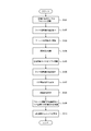
- FIG. 2 is a flowchart for explaining a tire management method according to an embodiment of the present invention by the tire management apparatus of FIG.
- a heavy duty pneumatic tire to be managed by the tire management device 10 is mounted, for example, on the front left side of the vehicle (step S101) and used as a front tire.
- This vehicle has six tires with two front wheels and four rear wheels, and the management target tire is a new tire, and about 1/3 of the tire life is the front wheel (front). After that, the remaining 2/3 is used in the rear wheel (rear), and is used in a normal usage form.
- the temperature detection unit 11 the temperature at a predetermined time in the tire air chamber of the management target tire is detected by the temperature detection sensor 14 of the tire pressure monitoring system (TPMS) incorporated in the management target tire (front tire). Is detected (step S102).
- the detected temperature information is output to the integrating unit 12 via a communication unit (ECU) 15 via wireless communication.
- the temperature every predetermined time in the tire air chamber detected by the temperature detection unit 11 is calculated by multiplying the load on the tire by the speed of the tire or the square of the load on the tire using the front tire conversion formula.
- the product is converted into a speed multiplication value (step S103), the converted multiplication value is integrated for a predetermined time (step S104), and the front integration result as the integration result is recorded.
- a heavy duty pneumatic tire to be managed which uses about 1/3 of the tire life on the front wheels (front), is mounted on the rear left side of the vehicle, for example (step S105), and used as a rear tire.
- the temperature detection sensor 14 of the tire air pressure monitoring system (TPMS) incorporated in the management target tire (rear tire) detects the temperature of the management target tire in the tire air chamber every predetermined time. It detects (step S106).
- the detected temperature information is output to the calculation unit 12 via wireless communication through a control unit (ECU) 15.
- ECU control unit
- the temperature for every predetermined time in the tire air chamber detected by the temperature detection unit 11 is calculated by multiplying the tire load and speed by the rear tire conversion formula or the tire square load and speed.
- the converted multiplication value is integrated for a predetermined time (step S108), and the rear integration result as the integration result is recorded.
- a front integration result that is an integration result at the time of front mounting and a rear integration result that is an integration result at the time of rear mounting are added (step S109). Thereby, the addition result of the multiplication value until now from the use start of the tire to be managed can be obtained.
- the obtained addition result is output to the determination unit 13.
- the expected life (tire life) data is prepared, and based on this data, from the addition result, the current tire usage status, for example, The expected time that can be used continuously is presented as a determination result. Presentation as a determination result in the determination unit 13 is performed for all the tires to be managed, and in the tire management method of the present embodiment, all the six tires mounted on the vehicle.
- the remaining tire life at the present time ( Tire life)
- Tire life for example, if the added value when using the front wheels and using the rear wheels is greater than the preset value, it is determined that the tire usage limit is near, and the tire life after that is predicted.
- the remaining usage time can be presented.
- the tire management method of the present embodiment can be realized by the tire management device 10 of the present embodiment, and the temperature / pressure data of the management target tire monitored in real time by the tire pressure monitoring system (TPMS).
- TPMS tire pressure monitoring system
- the temperature information in the tire air chamber can be obtained, and the current use status of the tire can be easily grasped based on the temperature information in the tire air chamber. Therefore, it is possible to realize a tire management method for performing effective tire management according to the use situation.
- the vehicle to which the tire to be managed is attached is not limited to six wheels.
- four wheels may be used, and not all six tires are managed, but one tire is managed. You may use for.
- the tire to be managed is not limited to being used as a rear wheel after being used as a front wheel, and may be used only at the same position. Further, the coefficients used in the conversion formula for the front tire and the conversion formula for the rear tire may be corrected using the internal pressure based on the data for each internal pressure in the tire air chamber.
- FIG. 3 is a diagram showing the relationship between the average daily mileage and the failure frequency for each of the failed parts 1 to 4.
- the failure part 1 has a low occurrence frequency when the average travel distance of the day is short (FIG. 3). Therefore, when the average mileage per day is short, the failure parts 2 to 4 can be considered as parts that may fail.
- the speed (average speed) for calculating TKPH or T 2 KPH is obtained by dividing the average daily mileage by 24 hours, so there is a correlation between TKPH or T 2 KPH and the failure part. There is. In addition, there is a correlation between TKPH or T 2 KPH obtained by the above conversion equation and the failure part.
- the determination unit 13 enters the air based on the addition value and a failure map prepared in advance and indicating the relationship between the addition value and one or more failure sites. It is preferably configured to determine a predicted failure location of the tire. This is because a site where a failure is predicted can be easily grasped based on the temperature inside the tire. Similarly, in the method of the present invention, the determination unit 13 uses the above-described addition value and a failure map prepared in advance to indicate the relationship between the addition value and one or more failure sites. It is preferable to determine a predicted failure portion of the entering tire.
- FIG. 4 is a diagram illustrating the detected temperature, the reference temperature, and the air temperature.
Landscapes
- Engineering & Computer Science (AREA)
- Mechanical Engineering (AREA)
- Physics & Mathematics (AREA)
- General Physics & Mathematics (AREA)
- Life Sciences & Earth Sciences (AREA)
- Environmental Sciences (AREA)
- Biochemistry (AREA)
- Environmental & Geological Engineering (AREA)
- Biodiversity & Conservation Biology (AREA)
- Health & Medical Sciences (AREA)
- Chemical & Material Sciences (AREA)
- Analytical Chemistry (AREA)
- Ecology (AREA)
- General Health & Medical Sciences (AREA)
- Immunology (AREA)
- Pathology (AREA)
- Tires In General (AREA)
- Testing Resistance To Weather, Investigating Materials By Mechanical Methods (AREA)
- Measuring Fluid Pressure (AREA)
Abstract
Description
そこで、このようなタイヤ内部の温度を空気入りタイヤの状況を正確に知ることに利用することができれば便利であるが、従来そのような技術はなかった。
この発明の目的は、タイヤ内部の温度に基づいて空気入りタイヤの使用状況を容易に把握することができる、タイヤ管理方法及びタイヤ管理装置を提供することである。
変換部により、検出した前記タイヤ空気室内の所定時間毎の温度を、タイヤにおける荷重と速度とを乗じた第1の乗算値又はタイヤにおける荷重の二乗と速度とを乗じた第2の乗算値に変換するステップと、
積算部により、前記第1の乗算値又は前記第2の乗算値を所定時間分積算した積算値を算出するステップと
を含むことを特徴とする。
前記温度検出部が検出した前記タイヤ空気室内の所定時間毎の温度を、タイヤにおける荷重と速度とを乗じた第1の乗算値又はタイヤにおける荷重の二乗と速度とを乗じた第2の乗算値に変換する変換部と、
前記第1の乗算値又は前記第2の乗算値を所定時間分積算した積算値を算出する積算部と
を備えることを特徴とする。
図1は、この発明の一実施の形態に係るタイヤ管理装置の構成を模式的に示すブロック図である。図1に示すように、本実施形態のタイヤ管理装置10は、温度検出部11と、計算部12と、判定部13とを有しており、計算部12からの情報に基づき、空気入りタイヤの現在使用状況を管理する。この例では、空気入りタイヤは、重荷重用空気入りタイヤ(以下、単にタイヤとも称する)建設・鉱山車両等に用いられる超大型の空気入りタイヤ(ORタイヤ)である。
温度検出部11は、例えば、タイヤ空気室内の温度を検出する温度検出センサ14と、車両に搭載された制御部(ECU)15を有しており、温度検出センサ14は、本実施形態では、タイヤ管理対象となる、車両の6本のタイヤそれぞれに配置されているが、必ずしも、6本のタイヤそれぞれに配置せず、必要に応じ、1本から6本未満のタイヤに配置して、それぞれを管理しても良い。
本実施形態においては、6個の温度検出センサ14及び制御部15により、6個の温度検出センサ14が検知したタイヤ内部の少なくとも温度の情報を無線通信で制御部15へ送信する。
計算部12は、変換部16と積算部17を有しており、計算部12に入力した、タイヤのタイヤ空気室内の所定時間毎の温度情報を、変換部16で変換し、積算部17で積算する。
変換部16が備える固有の変換式は、一例として、車両の種類、タイヤの種類、タイヤのサイズ、タイヤのトレッドパターン、タイヤケース構造等に基づくものであるが、これに限るものではない。
<フロントタイヤ用変換式>
TKPH=(検出温度-α)/β
T2KPH=(検出温度-γ)/δ
<リアタイヤ用変換式>
TKPH=(検出温度-ε)/ξ
T2KPH=(検出温度-η)/σ
とする。ここで、α,β,γ,δ,ε,ξ,η,σは、一例として上述した、車両の種類、タイヤの種類、タイヤのサイズ、タイヤのトレッドパターン、タイヤケース構造等に基づく係数である。
この積算部17は、先ず、該当するタイヤのフロント装着時、即ち、フロントタイヤとしての使用時における所定時間分積算を行い、フロント積算結果を記録する。
なお、本実施形態において、計算部12及び判定部13は、例えば、車両に搭載されている車両コントロール用のコンピュータに構成される機能部として実現されており、車両コントロール用コンピュータにおいて、判定に基づくタイヤ状態の管理を行う。
図2は、図1のタイヤ管理装置による、この発明の一実施の形態に係るタイヤ管理方法を説明するフローチャートである。図2に示すように、先ず、タイヤ管理装置10による管理対象の重荷重用空気入りタイヤを、例えば、車両のフロント左側に装着し(ステップS101)、フロントタイヤとして使用する。この車両は、前輪が2本、後輪が4本の6本のタイヤを有しており、管理対象のタイヤは、新品のタイヤであって、タイヤ寿命の1/3程を前輪(フロント)で用い、その後、残りの2/3程を後輪(リア)で用いる、通常の使用形態で使用する。
次に、計算部12において、温度検出部11が検出したタイヤ空気室内の所定時間毎の温度を、フロントタイヤ用変換式を用いて、タイヤにおける荷重と速度の乗算値又はタイヤにおける荷重の二乗と速度の乗算値に変換し(ステップS103)、変換された乗算値を所定時間分積算し(ステップS104)、積算結果であるフロント積算結果を記録する。
次に、温度検出部11において、管理対象のタイヤ(リアタイヤ)に組み込まれている、タイヤ空気圧監視システム(TPMS)の温度検出センサ14により、管理対象タイヤのタイヤ空気室内の所定時間毎の温度を検出する(ステップS106)。検出した温度情報は、制御部(ECU)15を経て無線通信を介し計算部12へ出力される。
続いて、管理対象のタイヤにおける、フロント装着時の積算結果であるフロント積算結果と、リア装着時の積算結果であるリア積算結果を、加算する(ステップS109)。これにより、管理対象のタイヤの使用開始からこれまでの乗算値の加算結果を得ることができる。得られた加算結果は、判定部13へ出力される。
補正温度=検出温度B(℃)+{(基準温度A(℃)-気温X(℃))}
との式を用い、検出温度に代えて、補正温度を用いることが好ましい。
Claims (10)
- 温度検出部により、車両の空気入りタイヤのタイヤ空気室内の所定時間毎の温度を検出するステップと、
変換部により、検出した前記タイヤ空気室内の所定時間毎の温度を、タイヤにおける荷重と速度とを乗じた第1の乗算値又はタイヤにおける荷重の二乗と速度とを乗じた第2の乗算値に変換するステップと、
積算部により、前記第1の乗算値又は前記第2の乗算値を所定時間分積算した積算値を算出するステップと
を含むことを特徴とする、タイヤ管理方法。 - 前記積算部により、フロント装着時の前記所定時間分の積算値と、リア装着時の前記所定時間分の積算値とを加算した加算値を算出するステップ
をさらに含む、請求項1に記載のタイヤ管理方法。 - 判定部により、予め用意したタイヤライフデータに基づいて、前記加算値から前記空気入りタイヤの使用状況を判定するステップ
をさらに含む、請求項2に記載のタイヤ管理方法。 - 前記判定部により、
前記加算値と、
予め用意した、前記加算値と1箇所又は2箇所以上の故障部位との関係を示す故障マップと、
に基づいて、前記空気入りタイヤの予測される故障部位を判定する、請求項3に記載のタイヤの管理方法。 - 前記空気入りタイヤは、重荷重用空気入りタイヤである、請求項1に記載のタイヤ管理方法。
- 車両の空気入りタイヤのタイヤ空気室内の所定時間毎の温度を検出する温度検出部と、
前記温度検出部が検出した前記タイヤ空気室内の所定時間毎の温度を、タイヤにおける荷重と速度とを乗じた第1の乗算値又はタイヤにおける荷重の二乗と速度とを乗じた第2の乗算値に変換する変換部と、
前記第1の乗算値又は前記第2の乗算値を所定時間分積算した積算値を算出する積算部と
を備えることを特徴とする、タイヤ管理装置。 - 前記積算部は、フロント装着時の前記所定時間分の積算値と、リア装着時の前記所定時間分の積算値とを加算した加算値を算出するように構成された、請求項6に記載のタイヤ管理装置。
- 前記判定部は、予め用意したタイヤライフデータに基づいて、前記加算値から前記空気入りタイヤの使用状況を判定するように構成された、請求項7に記載のタイヤ管理装置。
- 前記判定部は、
前記加算値と、
予め用意した、前記加算値と1箇所又は2箇所以上の故障部位との関係を示す故障マップと、
に基づいて、前記空気入りタイヤの予測される故障部位を判定するように構成された、請求項8に記載のタイヤの管理装置。 - 前記空気入りタイヤは、重荷重用空気入りタイヤである、請求項6に記載のタイヤ管理装置。
Priority Applications (4)
| Application Number | Priority Date | Filing Date | Title |
|---|---|---|---|
| CN201680065814.0A CN108291866B (zh) | 2015-11-10 | 2016-11-10 | 轮胎管理方法和轮胎管理设备 |
| EP16864323.7A EP3376205B1 (en) | 2015-11-10 | 2016-11-10 | Tire managing method and tire managing apparatus |
| JP2017550398A JP6673933B2 (ja) | 2015-11-10 | 2016-11-10 | タイヤ管理方法及びタイヤ管理装置 |
| US15/767,399 US10661618B2 (en) | 2015-11-10 | 2016-11-10 | Tire management method and tire management apparatus detecting temperature of tire at predetermined intervals |
Applications Claiming Priority (2)
| Application Number | Priority Date | Filing Date | Title |
|---|---|---|---|
| JP2015220413 | 2015-11-10 | ||
| JP2015-220413 | 2015-11-10 |
Publications (1)
| Publication Number | Publication Date |
|---|---|
| WO2017082362A1 true WO2017082362A1 (ja) | 2017-05-18 |
Family
ID=58696173
Family Applications (1)
| Application Number | Title | Priority Date | Filing Date |
|---|---|---|---|
| PCT/JP2016/083413 Ceased WO2017082362A1 (ja) | 2015-11-10 | 2016-11-10 | タイヤ管理方法及びタイヤ管理装置 |
Country Status (5)
| Country | Link |
|---|---|
| US (1) | US10661618B2 (ja) |
| EP (1) | EP3376205B1 (ja) |
| JP (1) | JP6673933B2 (ja) |
| CN (1) | CN108291866B (ja) |
| WO (1) | WO2017082362A1 (ja) |
Cited By (6)
| Publication number | Priority date | Publication date | Assignee | Title |
|---|---|---|---|---|
| WO2019049807A1 (ja) * | 2017-09-06 | 2019-03-14 | 株式会社ブリヂストン | タイヤの交換方法及びタイヤ交換指示装置 |
| WO2019081857A1 (fr) * | 2017-10-26 | 2019-05-02 | Compagnie Generale Des Etablissements Michelin | Procede d'evaluation des performances d'un pneumatique en cours d'utilisation |
| JP2020041899A (ja) * | 2018-09-10 | 2020-03-19 | 株式会社デンソー | タイヤシステム |
| WO2021201256A1 (ja) * | 2020-04-03 | 2021-10-07 | 横浜ゴム株式会社 | タイヤのケーシングライフ管理システム、及びタイヤのケーシングライフ管理方法 |
| WO2022102516A1 (ja) * | 2020-11-13 | 2022-05-19 | 株式会社ブリヂストン | タイヤ摩耗状態予測システム、タイヤ摩耗状態予測プログラムおよびタイヤ摩耗状態予測方法 |
| WO2022215316A1 (ja) * | 2021-04-09 | 2022-10-13 | 住友ゴム工業株式会社 | タイヤ状態判定システム、タイヤ状態判定装置、タイヤ状態判定方法、及びプログラム |
Citations (4)
| Publication number | Priority date | Publication date | Assignee | Title |
|---|---|---|---|---|
| JP2007168671A (ja) * | 2005-12-22 | 2007-07-05 | Toyota Motor Corp | タイヤダメージ判定装置 |
| JP2012116417A (ja) * | 2010-12-03 | 2012-06-21 | Yokohama Rubber Co Ltd:The | 空気入りタイヤ、タイヤ劣化状態判定システムおよびタイヤ劣化状態判定方法 |
| JP2014046879A (ja) * | 2012-09-03 | 2014-03-17 | Bridgestone Corp | タイヤケースライフ予測システム |
| WO2015040745A1 (ja) * | 2013-09-20 | 2015-03-26 | 株式会社小松製作所 | タイヤ異常管理システム及びタイヤ異常管理方法 |
Family Cites Families (19)
| Publication number | Priority date | Publication date | Assignee | Title |
|---|---|---|---|---|
| JPH04135902A (ja) * | 1990-09-28 | 1992-05-11 | Komatsu Ltd | タイヤの過負荷警報装置 |
| JP3300601B2 (ja) * | 1996-05-23 | 2002-07-08 | トヨタ自動車株式会社 | タイヤ空気圧検出装置 |
| FR2831107B1 (fr) * | 2001-10-18 | 2004-10-15 | Michelin Soc Tech | Procede d'estimation de la temperature de l'air de la cavite interne d'un pneumatique et application a la detection d'un fonctionnement anormal d'un systeme de roulage a plat |
| JP4059037B2 (ja) | 2002-08-28 | 2008-03-12 | トヨタ自動車株式会社 | タイヤ保護装置 |
| FR2856343B1 (fr) | 2003-06-18 | 2007-04-13 | Michelin Soc Tech | Procede pour predire l'usure d'un pneumatique et systeme pour sa mise en oeuvre |
| JP4680532B2 (ja) | 2004-06-02 | 2011-05-11 | 株式会社ブリヂストン | タイヤの動的状態推定方法とその装置 |
| FR2907375B1 (fr) | 2006-10-20 | 2009-01-16 | Michelin Soc Tech | Procede d'indication du vieillissement subi par un pneumatique |
| CN201004038Y (zh) | 2007-02-05 | 2008-01-09 | 华南理工大学 | 一种橡胶磨耗测试设备 |
| JP4903109B2 (ja) * | 2007-10-10 | 2012-03-28 | 株式会社ブリヂストン | 建設車両用タイヤトレッドパターン選定方法、および、それに用いられる建設車両用タイヤトレッドパターン選定支援システム |
| JP4753098B2 (ja) | 2008-06-03 | 2011-08-17 | 横浜ゴム株式会社 | タイヤ管理装置 |
| DE102010049088A1 (de) | 2010-10-21 | 2012-04-26 | Gm Global Technology Operations Llc (N.D.Ges.D. Staates Delaware) | Vorrichtung und Verfahren zur automatischen Reifendruckkontrolle an einem Fahrzeug sowie Verfahren zur Anzeige von Informationen zur Befüllung eines Fahrzeugreifens |
| JP5898519B2 (ja) | 2012-02-17 | 2016-04-06 | 株式会社ブリヂストン | タイヤ摩耗量推定方法及びタイヤ摩耗量推定装置 |
| DE102012217901B3 (de) * | 2012-10-01 | 2014-05-28 | Continental Automotive Gmbh | Verfahren, Steuergerät und System zum Ermitteln einer Profiltiefe eines Profils eines Reifens |
| DE102013220882B4 (de) | 2013-10-15 | 2019-05-29 | Continental Automotive Gmbh | Verfahren, Steuergerät und System zum Ermitteln einer Profiltiefe eines Profils zumindest eines Reifens |
| WO2015114792A1 (ja) * | 2014-01-31 | 2015-08-06 | 株式会社日立製作所 | 保守運用支援システム、保守運用支援方法、保守運用支援プログラム |
| US9442045B2 (en) * | 2014-04-03 | 2016-09-13 | The Goodyear Tire & Rubber Company | Model-based longitudinal stiffness estimation system and method |
| KR101566748B1 (ko) * | 2014-06-02 | 2015-11-06 | 현대자동차 주식회사 | 모터 구동 차량의 타이어 압력 모니터링 시스템 및 이를 이용한 타이어 압력 모니터링 방법 |
| US9821611B2 (en) * | 2015-10-21 | 2017-11-21 | The Goodyear Tire & Rubber Company | Indirect tire wear state estimation system |
| JP6697989B2 (ja) * | 2016-09-12 | 2020-05-27 | 本田技研工業株式会社 | 間接式タイヤ空気圧監視システム |
-
2016
- 2016-11-10 WO PCT/JP2016/083413 patent/WO2017082362A1/ja not_active Ceased
- 2016-11-10 EP EP16864323.7A patent/EP3376205B1/en not_active Not-in-force
- 2016-11-10 CN CN201680065814.0A patent/CN108291866B/zh not_active Expired - Fee Related
- 2016-11-10 US US15/767,399 patent/US10661618B2/en active Active
- 2016-11-10 JP JP2017550398A patent/JP6673933B2/ja not_active Expired - Fee Related
Patent Citations (4)
| Publication number | Priority date | Publication date | Assignee | Title |
|---|---|---|---|---|
| JP2007168671A (ja) * | 2005-12-22 | 2007-07-05 | Toyota Motor Corp | タイヤダメージ判定装置 |
| JP2012116417A (ja) * | 2010-12-03 | 2012-06-21 | Yokohama Rubber Co Ltd:The | 空気入りタイヤ、タイヤ劣化状態判定システムおよびタイヤ劣化状態判定方法 |
| JP2014046879A (ja) * | 2012-09-03 | 2014-03-17 | Bridgestone Corp | タイヤケースライフ予測システム |
| WO2015040745A1 (ja) * | 2013-09-20 | 2015-03-26 | 株式会社小松製作所 | タイヤ異常管理システム及びタイヤ異常管理方法 |
Cited By (16)
| Publication number | Priority date | Publication date | Assignee | Title |
|---|---|---|---|---|
| JP2019043454A (ja) * | 2017-09-06 | 2019-03-22 | 株式会社ブリヂストン | タイヤの交換方法及びタイヤ交換指示装置 |
| WO2019049807A1 (ja) * | 2017-09-06 | 2019-03-14 | 株式会社ブリヂストン | タイヤの交換方法及びタイヤ交換指示装置 |
| US11385136B2 (en) | 2017-09-06 | 2022-07-12 | Bridgestone Corporation | Tire replacement method and tire replacement instruction device |
| WO2019081857A1 (fr) * | 2017-10-26 | 2019-05-02 | Compagnie Generale Des Etablissements Michelin | Procede d'evaluation des performances d'un pneumatique en cours d'utilisation |
| JP7095508B2 (ja) | 2018-09-10 | 2022-07-05 | 株式会社デンソー | タイヤシステム |
| JP2020041899A (ja) * | 2018-09-10 | 2020-03-19 | 株式会社デンソー | タイヤシステム |
| WO2021201256A1 (ja) * | 2020-04-03 | 2021-10-07 | 横浜ゴム株式会社 | タイヤのケーシングライフ管理システム、及びタイヤのケーシングライフ管理方法 |
| JP2021160691A (ja) * | 2020-04-03 | 2021-10-11 | 横浜ゴム株式会社 | タイヤのケーシングライフ管理システム、及びタイヤのケーシングライフ管理方法 |
| US20230130069A1 (en) * | 2020-04-03 | 2023-04-27 | The Yokohama Rubber Co., Ltd. | Tire casing life management system and tire casing life management method |
| JP7453531B2 (ja) | 2020-04-03 | 2024-03-21 | 横浜ゴム株式会社 | タイヤのケーシングライフ管理システム、及びタイヤのケーシングライフ管理方法 |
| US12350975B2 (en) * | 2020-04-03 | 2025-07-08 | The Yokohama Rubber Co., Ltd. | Tire casing life management system and tire casing life management method |
| JP2022078630A (ja) * | 2020-11-13 | 2022-05-25 | 株式会社ブリヂストン | タイヤ摩耗状態予測システム、タイヤ摩耗状態予測プログラムおよびタイヤ摩耗状態予測方法 |
| WO2022102516A1 (ja) * | 2020-11-13 | 2022-05-19 | 株式会社ブリヂストン | タイヤ摩耗状態予測システム、タイヤ摩耗状態予測プログラムおよびタイヤ摩耗状態予測方法 |
| JP7407100B2 (ja) | 2020-11-13 | 2023-12-28 | 株式会社ブリヂストン | タイヤ摩耗状態予測システム、タイヤ摩耗状態予測プログラムおよびタイヤ摩耗状態予測方法 |
| US12535386B2 (en) | 2020-11-13 | 2026-01-27 | Bridgestone Corporation | Tire wear condition prediction system, tire wear condition prediction program and tire wear condition prediction method |
| WO2022215316A1 (ja) * | 2021-04-09 | 2022-10-13 | 住友ゴム工業株式会社 | タイヤ状態判定システム、タイヤ状態判定装置、タイヤ状態判定方法、及びプログラム |
Also Published As
| Publication number | Publication date |
|---|---|
| JPWO2017082362A1 (ja) | 2018-08-30 |
| EP3376205B1 (en) | 2020-12-30 |
| CN108291866A (zh) | 2018-07-17 |
| JP6673933B2 (ja) | 2020-03-25 |
| EP3376205A4 (en) | 2018-09-19 |
| CN108291866B (zh) | 2020-08-11 |
| US20180304703A1 (en) | 2018-10-25 |
| US10661618B2 (en) | 2020-05-26 |
| EP3376205A1 (en) | 2018-09-19 |
Similar Documents
| Publication | Publication Date | Title |
|---|---|---|
| JP6673933B2 (ja) | タイヤ管理方法及びタイヤ管理装置 | |
| US11458777B2 (en) | Tread wear monitoring system and method | |
| US11458776B2 (en) | Tread wear monitoring system and method | |
| JP6265411B2 (ja) | 車両重量および重心推定システムおよび方法 | |
| EP2740640B1 (en) | Tire slip angle estimation system and method | |
| US10882366B2 (en) | Electronic wheel unit for a vehicle wheel, and method for operating an electronic wheel unit of this kind | |
| US20230130069A1 (en) | Tire casing life management system and tire casing life management method | |
| EP4304876B1 (en) | System and method for estimation of tread depth from tire pressure and/or temperature measurements | |
| CN109641496B (zh) | 用于确定车轮载荷的方法和设备以及用于确定车辆重量的方法和设备 | |
| KR101907689B1 (ko) | 인텔리전트 타이어 수명예측 및 알림방법. | |
| WO2013139977A1 (en) | System and method for monitoring vehicle load dynamics | |
| EP3785944A1 (en) | Tire wear state estimation system and method employing footprint shape factor | |
| CN105555555A (zh) | 确定车辆轮胎的理论胎压与实际胎压的压力比的方法和系统 | |
| AU2016238669A1 (en) | Method for determining the temperature of an internal part of the materials of a tyre | |
| JP2025522107A (ja) | タイヤ空気圧損失の検出 | |
| CN112533772B (zh) | 轮胎损坏检测系统和方法 | |
| JP6594334B2 (ja) | タイヤ故障部位予測システム及びタイヤ故障部位予測方法 | |
| KR101216448B1 (ko) | 차량의 휠에 장착된 압력 센서에 의해서 전송되는 정보를필터링하기 위한 방법 및 장치 | |
| CN118849675B (zh) | 胎压监测方法、装置、电子设备及存储介质 | |
| US11691464B2 (en) | Methods for detecting and locating a thermal anomaly for a mounted assembly of a vehicle | |
| JP2014532578A5 (ja) | ||
| KR101499879B1 (ko) | 타이어 압력 모니터링 시스템 및 방법 | |
| JP5955812B2 (ja) | 位置特定装置及び車輪側ユニット | |
| CN121105618A (zh) | 一种间接式胎压监测方法及系统 | |
| CN110958952A (zh) | 用于诊断车辆轮胎的充气状况的方法 |
Legal Events
| Date | Code | Title | Description |
|---|---|---|---|
| 121 | Ep: the epo has been informed by wipo that ep was designated in this application |
Ref document number: 16864323 Country of ref document: EP Kind code of ref document: A1 |
|
| ENP | Entry into the national phase |
Ref document number: 2017550398 Country of ref document: JP Kind code of ref document: A |
|
| WWE | Wipo information: entry into national phase |
Ref document number: 15767399 Country of ref document: US |
|
| NENP | Non-entry into the national phase |
Ref country code: DE |
|
| WWE | Wipo information: entry into national phase |
Ref document number: 2016864323 Country of ref document: EP |