WO2017085768A1 - 工具経路生成方法 - Google Patents
工具経路生成方法 Download PDFInfo
- Publication number
- WO2017085768A1 WO2017085768A1 PCT/JP2015/082151 JP2015082151W WO2017085768A1 WO 2017085768 A1 WO2017085768 A1 WO 2017085768A1 JP 2015082151 W JP2015082151 W JP 2015082151W WO 2017085768 A1 WO2017085768 A1 WO 2017085768A1
- Authority
- WO
- WIPO (PCT)
- Prior art keywords
- tool path
- function
- curved surface
- tool
- workpiece
- Prior art date
- Legal status (The legal status is an assumption and is not a legal conclusion. Google has not performed a legal analysis and makes no representation as to the accuracy of the status listed.)
- Ceased
Links
Images



Classifications
-
- G—PHYSICS
- G05—CONTROLLING; REGULATING
- G05B—CONTROL OR REGULATING SYSTEMS IN GENERAL; FUNCTIONAL ELEMENTS OF SUCH SYSTEMS; MONITORING OR TESTING ARRANGEMENTS FOR SUCH SYSTEMS OR ELEMENTS
- G05B19/00—Program-control systems
- G05B19/02—Program-control systems electric
- G05B19/18—Numerical control [NC], i.e. automatically operating machines, in particular machine tools, e.g. in a manufacturing environment, so as to execute positioning, movement or co-ordinated operations by means of program data in numerical form
- G05B19/401—Numerical control [NC], i.e. automatically operating machines, in particular machine tools, e.g. in a manufacturing environment, so as to execute positioning, movement or co-ordinated operations by means of program data in numerical form characterised by control arrangements for measuring, e.g. calibration and initialisation, measuring workpiece for machining purposes
-
- G—PHYSICS
- G05—CONTROLLING; REGULATING
- G05B—CONTROL OR REGULATING SYSTEMS IN GENERAL; FUNCTIONAL ELEMENTS OF SUCH SYSTEMS; MONITORING OR TESTING ARRANGEMENTS FOR SUCH SYSTEMS OR ELEMENTS
- G05B19/00—Program-control systems
- G05B19/02—Program-control systems electric
- G05B19/18—Numerical control [NC], i.e. automatically operating machines, in particular machine tools, e.g. in a manufacturing environment, so as to execute positioning, movement or co-ordinated operations by means of program data in numerical form
- G05B19/19—Numerical control [NC], i.e. automatically operating machines, in particular machine tools, e.g. in a manufacturing environment, so as to execute positioning, movement or co-ordinated operations by means of program data in numerical form characterised by positioning or contouring control systems, e.g. to control position from one programmed point to another or to control movement along a programmed continuous path
-
- G—PHYSICS
- G05—CONTROLLING; REGULATING
- G05B—CONTROL OR REGULATING SYSTEMS IN GENERAL; FUNCTIONAL ELEMENTS OF SUCH SYSTEMS; MONITORING OR TESTING ARRANGEMENTS FOR SUCH SYSTEMS OR ELEMENTS
- G05B2219/00—Program-control systems
- G05B2219/30—Nc systems
- G05B2219/35—Nc in input of data, input till input file format
- G05B2219/35151—Modeling geometric, generation or forming of curved surface
-
- G—PHYSICS
- G05—CONTROLLING; REGULATING
- G05B—CONTROL OR REGULATING SYSTEMS IN GENERAL; FUNCTIONAL ELEMENTS OF SUCH SYSTEMS; MONITORING OR TESTING ARRANGEMENTS FOR SUCH SYSTEMS OR ELEMENTS
- G05B2219/00—Program-control systems
- G05B2219/30—Nc systems
- G05B2219/35—Nc in input of data, input till input file format
- G05B2219/35261—Use of mathematical expression, functional equation
-
- G—PHYSICS
- G05—CONTROLLING; REGULATING
- G05B—CONTROL OR REGULATING SYSTEMS IN GENERAL; FUNCTIONAL ELEMENTS OF SUCH SYSTEMS; MONITORING OR TESTING ARRANGEMENTS FOR SUCH SYSTEMS OR ELEMENTS
- G05B2219/00—Program-control systems
- G05B2219/30—Nc systems
- G05B2219/37—Measurements
- G05B2219/37576—Post-process, measure worpiece after machining, use results for new or same
-
- G—PHYSICS
- G05—CONTROLLING; REGULATING
- G05B—CONTROL OR REGULATING SYSTEMS IN GENERAL; FUNCTIONAL ELEMENTS OF SUCH SYSTEMS; MONITORING OR TESTING ARRANGEMENTS FOR SUCH SYSTEMS OR ELEMENTS
- G05B2219/00—Program-control systems
- G05B2219/30—Nc systems
- G05B2219/45—Nc applications
- G05B2219/45157—Grind optical lens
-
- G—PHYSICS
- G05—CONTROLLING; REGULATING
- G05B—CONTROL OR REGULATING SYSTEMS IN GENERAL; FUNCTIONAL ELEMENTS OF SUCH SYSTEMS; MONITORING OR TESTING ARRANGEMENTS FOR SUCH SYSTEMS OR ELEMENTS
- G05B2219/00—Program-control systems
- G05B2219/30—Nc systems
- G05B2219/50—Machine tool, machine tool null till machine tool work handling
- G05B2219/50057—Compensation error by probing test, machined piece, post or pre process
Definitions
- the present invention relates to a method for generating a tool path to be supplied to an NC device of a machine tool that processes a workpiece by moving the tool and the workpiece relative to each other.
- Patent Document 1 in a method of manufacturing a lens for an optical scanning device used in a laser beam printer, a digital copying machine, etc., the lens is injection molded with a mold, and the surface shape of the molded lens is measured and measured. Calculate the shape error by subtracting the design value (design shape) from the value (measured shape data), invert the sign of the calculated shape error, and superimpose it on the previous design shape as a correction amount to form the lens A method of manufacturing a mold for use is described.
- the present invention has a technical problem to solve such problems of the prior art, and a tool capable of further correcting the tool path so as to reduce the shape error while maintaining the characteristics of the function representing the curved surface.
- the object is to provide a route generation method.
- a plurality of coefficients that define the first curved surface are determined.
- a first function consisting of a polynomial having a first tool path is generated based on the first function, and the first tool path is input to an NC device of a machine tool, Machining the workpiece by moving the tool relative to the workpiece along the tool path, measuring the shape of the workpiece at a plurality of measurement points on the surface of the machined workpiece, and for each of the measurement points, A symmetric position with respect to the first curved surface is calculated in a direction perpendicular to the first curved surface as a correction point, and a second curved surface representing the second curved surface based on a series of position data of the correction point is calculated.
- 2 function, the second tool based on the second function Tool path generation method to generate a road is provided.
- a symmetric position with respect to the first curved surface is calculated in a direction perpendicular to the first curved surface to obtain a correction point, and a series of position data of the correction point. Since the second function representing the second curved surface that best fits the above is obtained, and the second tool path is generated based on the second function, correction suitable for the first curved surface shape characteristic is possible. It becomes.
- FIG. 6 is a schematic diagram showing a processed surface, a design surface (first curved surface), and a corrected curved surface (second curved surface). It is the schematic for demonstrating the tool path
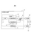
- the tool path generation device 10 includes an input unit 12, a storage unit 14, a tool path generation unit 16, and a coefficient calculation unit 18 as main components.
- the tool path generated by the tool path generation unit 16 is output to the machine tool 100.
- the machine tool 100 includes, for example, a main shaft (not shown) that is rotatably supported, a table (not shown) that fixes the work 108 so as to face the main shaft, and the main shaft and the work 108 at least X.
- a machining center including a processing machine such as a milling machine provided with a feed device (not shown) for relative movement in three orthogonal directions of Y, Z, and an NC device for controlling the tool feed of the processing machine. be able to.
- the processing machine has a lathe with a workpiece 108 attached to a main shaft that is rotatably supported, a tool that is fixed to a tool post (not shown), and a feed that relatively moves the tool post in three orthogonal X, Y, and Z directions.
- the apparatus may be controlled by an NC apparatus.
- the machine tool 100 is provided with a measuring instrument 102 for measuring the machined surface of the machined workpiece W. The measurement result obtained by the measuring instrument 102 is supplied to the coefficient calculation unit 18.
- the input unit 12 can be configured by a keyboard, a touch panel, or the like that can input mathematical formulas and numerical values to the storage unit 14.
- a function composed of a polynomial having a plurality of coefficients defining a surface to be formed on the workpiece 108 and each numerical value of the plurality of coefficients are input to the storage unit 14 via the input unit 12.
- the storage unit 14 can be composed of a flash memory or a hard drive, and has at least a function storage area 20 for storing the functions and numerical values input from the input unit 12 and a coefficient storage area 22.
- the tool path generation unit 16 generates a tool path or NC data based on the function stored in the storage unit 14 and the numerical value of each coefficient of the function, and the tool path or NC data is stored in the machine tool 100 at predetermined time intervals. Supplied to the NC device.
- the machine tool 100 processes the workpiece by moving the tool relative to the workpiece along the tool path supplied to the NC device.
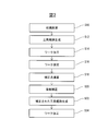
- the first function and the numerical value of the coefficient of the first function are input from the input unit 12 to the storage unit 14, and initialization is performed (step S10).
- the first function may be a polynomial having a plurality of coefficients that define a curved surface that is a surface to be formed on the workpiece 108.
- the workpiece 108 is a mold for molding an aspheric lens
- the first function is a polynomial that defines the aspheric surface of the lens. More specifically, the first function is generally expressed by the following equation (1).
- c is a curvature and K is a conic constant.
- a to D are aspheric coefficients, which are input from the input unit 12 in the initial setting in step S10. Further, as will be described later, the aspherical coefficients A to D are calculated and corrected by the coefficient calculation unit 18.
- the tool path generation unit 16 When the initial setting is completed, the tool path generation unit 16 generates a tool path or machining data based on the input function, in this embodiment, the expression (1) and the numerical values of the respective aspheric coefficients (A to D) (Ste S12).
- the generated tool path or machining data is output to the NC device of the machine tool 100 at predetermined time intervals, and the machine tool 100 machines the workpiece 108 (step S14).
- the machine tool 100 is a machining center having a ball end mill 106 as a tool attached to the tip of the main shaft.
- the Z axis is defined in the direction of the central axis of the ball end mill 106
- the X axis and the Y axis are defined in the direction perpendicular to the Z axis.
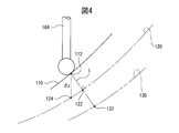
- the measuring instrument 102 may include a touch sensor having a probe 104 that can be attached to the tip of the spindle of the machine tool 100. In that case, when the tip of the probe 104 contacts the surface of the workpiece 108, a skip signal is generated from the measuring device 102, and the skip signal is used as a trigger to trigger the X axis, Y axis, and Z axis of the feed device of the machine tool 100. Can be output to the coefficient calculator 18.
- the machining surface 110 is measured at a plurality of measurement points along the machining surface 110, and the X, Y, and Z coordinates of each measurement point are output to the coefficient calculation unit 18.
- the design surface 120 is an aspherical surface represented by Expression (1), and the optical axis of the molded lens is parallel to the Z-axis.
- the processing surface 110 does not completely coincide with the design surface 120 and includes an error ⁇ z that is a difference in the Z-axis direction between the measurement point 112 on the processing surface 110 and the design surface 120.
- FIG. 4 shows that ⁇ z is a positive value, indicating that cutting is insufficient. However, ⁇ z may be a negative value, resulting in excessive cutting.
- the coordinates of points that are symmetric with respect to the designed surface 120 are calculated and set as correction points 132 (step S18). . More specifically, first, a straight line L that passes through the measurement point 112 and is perpendicular to the designed surface 120 is calculated. In FIG. 4, a point 122 is a leg of a perpendicular line L drawn from the measurement point 112 to the design surface 120. Next, the coordinates of the point 132 symmetrical to the measurement point 112 with respect to the design surface 120 on the straight line L are calculated. In the present application, the symmetrical point 132 of the measurement point 112 is referred to as a correction point.
- a virtual curved surface (second curved surface) that best fits the coordinate data group of the series of correction points 132 is determined.
- the second curved surface which is a virtual curved surface, is calculated by the coefficient calculator 18 based on the coordinate data group of the measurement point 112 measured by the measuring instrument 102 (1).
- Expression (1) in which the aspheric coefficients A to D are corrected is the second function.
- the tool path generation unit 16 is based on the function stored in the function storage area 20 and the corrected aspheric coefficients A to D calculated by the coefficient calculation unit 18 and stored in the coefficient storage area 22. That is, a second tool path is generated based on the second function (step S22).
- the machine tool 100 processes the workpiece 108 according to the second tool path (step S24).
- U and v are one point in the parameter space
- x, y and z represent one point in the three-dimensional space corresponding to u and v.
- a correction coefficient is introduced into the function f.
- the coefficient needs to be able to express the correction amount sufficiently.
- the function introducing the correction coefficient is F
- the correction coefficient vector is a
- the coefficient vector order is N
- the expression representing the shape of an optical component such as a lens already includes aspherical coefficients A to D for correcting optical characteristics.
- the aspherical coefficients A to D can be used as the correction coefficients a 1 to a N.
- the coefficient vector a that appears thereafter can be dealt with by rereading it as a difference from the design values of the respective aspheric surfaces A to D.
- the processing of the workpiece 108 in step S14 is processing of a curved surface when the coefficient vector a is a zero vector. When the coefficient vector a is a zero vector, the function f and the function F are equal.
- the measurement point 112 is acquired as a point group in the three-dimensional space. If r is a group including a series of measurement points 112 and M is the number of measurement points 112, It is.
- the group r of measurement points 112 is a collection of points in the three-dimensional space, and this is converted into a point consisting of a point on the parameter space (uv space) and a signed distance.
- the signed distance is a distance from a point in the three-dimensional space corresponding to a point on the parameter space (uv space), a distance in the normal direction at that point is positive, and a normal direction Is a real number with negative distance in the opposite direction.
- This conversion can be processed as follows, for example. First, points are generated in a grid on the design surface or parameter space (uv space) representing the first curved surface (Process I), and then each of the points generated by Process I is generated in the three-dimensional space. And correspond to the points (Process II). At this time, a data structure such as a kd tree (k-dimensional tree) is generated with respect to the points in the three-dimensional space converted by the processing II, and a point close to any point in the arbitrary three-dimensional space is generated at high speed. If it is in a state where it can be searched, the subsequent processing can be processed at high speed. Since this search does not necessarily need to be the closest point, various algorithms for approximate nearest neighbor search may be applied.
- kd tree k-dimensional tree
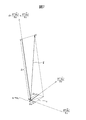
- one of the measurement points 112 is set as a processing target point q (see FIGS. 6 and 7).
- a point closest to the target point q is searched, and this is defined as q1.
- a point on the corresponding parameter space (uv space) is set to p1. That means
- the measurement point 112 is converted into a signed distance from a point on the parameter space.
- the converted point group is represented as R as follows.
- the error ⁇ z can be canceled out.
- the error ⁇ z of the coordinate data of the series of measurement points 112 is calculated as the w component of the converted point group R. That is, when the u and v coordinates of each point in the point group R are converted by the function F, the coefficient vector a is fitted so that the w component moves in the direction opposite to the normal direction as compared with the case of conversion by the function f. It ’s fine.
- the fitting process as an optimization problem, it can be considered as a problem of minimizing the following objective function E.
- N is a normal vector, but the correction amount is usually a small value, and the change in the normal direction due to correction is often negligible.
- the normal direction is not calculated every time, but the normal direction calculated by the equation (4) can be stored and used for the calculation.
- Equation (8) can be calculated by, for example, the Levenberg-Marquardt method because of the square sum minimization problem.
- the corrected function (second function) can be obtained by substituting the coefficient a into the function F.
Landscapes
- Engineering & Computer Science (AREA)
- Human Computer Interaction (AREA)
- Manufacturing & Machinery (AREA)
- Physics & Mathematics (AREA)
- General Physics & Mathematics (AREA)
- Automation & Control Theory (AREA)
- Numerical Control (AREA)
Abstract
Description
図1において、工具経路生成装置10は、入力部12、記憶部14、工具経路生成部16、係数演算部18を主要な構成要素として具備する。工具経路生成部16で生成された工具経路は、工作機械100に出力される。
先ず、入力部12から第1の関数および該第1の関数の係数の数値が記憶部14に入力され、初期設定が実行される(ステップS10)。第1の関数は、ワーク108に形成すべき表面である曲面を定義する複数の係数を有した多項式とすることができる。本実施形態では、ワーク108は非球面レンズを成形するための金型であり、第1の関数は、該レンズの非球面表面を定義する多項式である。より詳細には、第1の関数は一般的に以下の式(1)にて表される。

一般的に、パラメータ空間上の点pから3次元空間内の点qに変換する関数fとすると、以下のpとqの関係は以下の式に(2)にて表される。







まず、設計上の表面または第1の曲面を表すパラメータ空間(u-v空間)上に点を格子状に生成し(処理I)、次いで、処理Iで生成した点の各々を3次元空間内の点に変換し対応付ける(処理II)。このとき、処理IIで変換した3次元空間内の点に対してk-d木(k-dimensional tree)のようなデータ構造を生成して、任意の3次元空間内の点から近い点を高速に検索できる状態にすると後の処理を高速に処理できる。この検索は必ずしも最も近い点である必要はないため、近似最近傍探索の各種アルゴリズムを適用してもよい。

(処理1)処理対象点piでの関数fのu偏微分、v偏微分を求め、それぞれ∂f/∂u、∂f/∂vとする。
(処理2)∂f/∂uと、∂f/∂vから点piでの法線方向を計算する。ここで、法線ベクトルは以下の式(4)で表される。



また、Δu、Δv、Δnは以下の式(5)~(7)で表される。







(処理5)piのu成分にΔu、v成分にΔvを加算したものをp(i+1)、p(i+1)を3次元空間上の点に変換したものをq(i+1)として、(処理1)に戻って処理1~処理4を実行する。つまり、



12 入力部
14 記憶部
16 工具経路生成部
18 係数演算部
20 関数記憶領域
22 係数記憶領域
100 工作機械
102 測定器
104 プローブ
106 ボールエンドミル
108 ワーク
110 加工面
112 測定点
120 設計上の表面
132 補正点
Claims (4)
- 3次元空間内で曲面を定義する関数に基づいて工具経路を生成する工具経路生成方法において、
第1の曲面を定義する複数の係数を有する多項式より成る第1の関数を入力し、
前記第1の関数に基づいて第1の工具経路を生成し、
前記第1の工具経路を工作機械のNC装置に入力して、該第1の工具経路に沿って工具をワークに対して相対移動させて該ワークを加工し、
加工された前記ワークの表面上の複数の測定点で該ワークの形状を測定し、
前記測定点の各々につき、前記第1の曲面に対して垂直な方向に前記第1の曲面に対しての対称な位置を演算して補正点とし、
前記補正点の一連の位置データに基づいて第2の曲面を表す第2の関数を求め、
前記第2の関数に基づいて第2の工具経路を生成することを特徴とした工具経路生成方法。 - 前記第2の関数は、前記第2の曲面が、第1の関数の前記複数の係数を変更することによって、前記補正点の一連の位置データに最もよく当てはまるよう定義される請求項1に記載の工具経路生成方法。
- 前記第2の関数は、前記補正点の一連の位置データに基づき最小二乗法を用いて求められる請求項2に記載の工具経路生成方法。
- 前記第1と第2の関数は一般的に以下の式にて表される請求項1~3の何れか1項に記載の工具経路生成方法。

Priority Applications (5)
| Application Number | Priority Date | Filing Date | Title |
|---|---|---|---|
| CN201580084570.6A CN108351634B (zh) | 2015-11-16 | 2015-11-16 | 刀具路径生成方法 |
| JP2017551411A JP6567073B2 (ja) | 2015-11-16 | 2015-11-16 | 工具経路生成方法 |
| EP15908708.9A EP3379353B1 (en) | 2015-11-16 | 2015-11-16 | Tool path generating method |
| US15/775,176 US10599124B2 (en) | 2015-11-16 | 2015-11-16 | Tool path generating method |
| PCT/JP2015/082151 WO2017085768A1 (ja) | 2015-11-16 | 2015-11-16 | 工具経路生成方法 |
Applications Claiming Priority (1)
| Application Number | Priority Date | Filing Date | Title |
|---|---|---|---|
| PCT/JP2015/082151 WO2017085768A1 (ja) | 2015-11-16 | 2015-11-16 | 工具経路生成方法 |
Publications (1)
| Publication Number | Publication Date |
|---|---|
| WO2017085768A1 true WO2017085768A1 (ja) | 2017-05-26 |
Family
ID=58718474
Family Applications (1)
| Application Number | Title | Priority Date | Filing Date |
|---|---|---|---|
| PCT/JP2015/082151 Ceased WO2017085768A1 (ja) | 2015-11-16 | 2015-11-16 | 工具経路生成方法 |
Country Status (5)
| Country | Link |
|---|---|
| US (1) | US10599124B2 (ja) |
| EP (1) | EP3379353B1 (ja) |
| JP (1) | JP6567073B2 (ja) |
| CN (1) | CN108351634B (ja) |
| WO (1) | WO2017085768A1 (ja) |
Cited By (2)
| Publication number | Priority date | Publication date | Assignee | Title |
|---|---|---|---|---|
| US20210220993A1 (en) * | 2018-02-08 | 2021-07-22 | Abb Schweiz Ag | Method and apparatus for adjusting robot motion path |
| CN117102899A (zh) * | 2023-10-20 | 2023-11-24 | 浙江大学 | 基于超精密伺服加工系统的曲面光栅加工装置及加工方法 |
Families Citing this family (4)
| Publication number | Priority date | Publication date | Assignee | Title |
|---|---|---|---|---|
| CN109947045B (zh) * | 2019-03-27 | 2021-09-10 | 南京工业大学 | 一种基于极坐标机床的免校正数控倒角算法 |
| US11745305B2 (en) * | 2019-07-05 | 2023-09-05 | Moore Nanotechnology Systems, LLC | System and method for correcting machining error during a precision jig grinding process |
| CN114101741B (zh) * | 2021-12-01 | 2022-10-14 | 北京星航机电装备有限公司 | 一种数控加工在线检测及自动补偿的方法 |
| JP2025518426A (ja) * | 2022-05-13 | 2025-06-17 | メープル アドバンスド ロボティクス インコーポレイテッド | 物体の表面フィッティング、パスプレーニング、および表面処理のためのシステムおよび方法 |
Citations (5)
| Publication number | Priority date | Publication date | Assignee | Title |
|---|---|---|---|---|
| JPH09159914A (ja) * | 1995-12-11 | 1997-06-20 | Hitachi Ltd | 投写用レンズ装置及びこれを用いた背面投写型画像ディスプレイ装置 |
| JPH10240322A (ja) * | 1997-02-26 | 1998-09-11 | Olympus Optical Co Ltd | 曲面切削加工方法 |
| US7463425B1 (en) * | 2007-07-17 | 2008-12-09 | Zoom Precision Optical Electronic Co., Ltd. | Zoom lens system |
| JP2010146176A (ja) * | 2008-12-17 | 2010-07-01 | Fanuc Ltd | 回転軸を有する工作機械用の数値制御装置 |
| JP2012035399A (ja) * | 2010-08-11 | 2012-02-23 | Shin Nippon Koki Co Ltd | 補正マトリクス導出装置、誤差補正装置及び工作機械 |
Family Cites Families (13)
| Publication number | Priority date | Publication date | Assignee | Title |
|---|---|---|---|---|
| JPH0815701B2 (ja) * | 1993-05-17 | 1996-02-21 | 株式会社エフ・エーラボ | 三次元加工方法 |
| US5946142A (en) | 1995-12-11 | 1999-08-31 | Hitachi Ltd. | Projection lens system and projection image display apparatus using the same |
| JP4461256B2 (ja) * | 2005-02-28 | 2010-05-12 | 国立大学法人東京農工大学 | 表面加工制御方法、及び表面加工制御プログラム |
| CN100437601C (zh) * | 2006-07-24 | 2008-11-26 | 西安飞机工业(集团)有限责任公司 | 一种用于自动钻铆托架变形的修补数据处理方法 |
| CN100585522C (zh) * | 2007-07-20 | 2010-01-27 | 天津大学 | 一种带有金刚石刀具前角补偿的超精密车削方法 |
| GB2452091B (en) * | 2007-08-24 | 2013-01-02 | Zeeko Ltd | Computer controlled work tool apparatus and method |
| JP2009136937A (ja) * | 2007-12-04 | 2009-06-25 | Olympus Corp | 加工方法、加工プログラム、加工装置 |
| JP2012088601A (ja) | 2010-10-21 | 2012-05-10 | Canon Inc | 光学素子の製造方法及びそれより製造された光学素子 |
| CN102078968B (zh) * | 2011-01-20 | 2012-06-20 | 天津大学 | 一种带有斜面的光学镜的超精密车削加工方法 |
| JP5342665B2 (ja) * | 2012-03-12 | 2013-11-13 | ファナック株式会社 | 渦巻き状計測経路に沿って計測を行うレンズ形状加工方法およびレンズ形状加工装置 |
| US9383742B2 (en) * | 2013-03-08 | 2016-07-05 | Pratt & Whitney Canada Corp. | System and method for positioning error compensation during manufacturing of complex-shaped gas turbine engine parts |
| CA2975871C (en) * | 2015-02-18 | 2023-04-18 | Xebec Technology Co., Ltd. | Path calculation program, processing device, path calculation method, tool, and processed article |
| CN104924633B (zh) * | 2015-04-30 | 2017-07-28 | 西北工业大学 | 一种用于成形槽形件的模具型面的设计方法 |
-
2015
- 2015-11-16 WO PCT/JP2015/082151 patent/WO2017085768A1/ja not_active Ceased
- 2015-11-16 CN CN201580084570.6A patent/CN108351634B/zh not_active Expired - Fee Related
- 2015-11-16 US US15/775,176 patent/US10599124B2/en active Active
- 2015-11-16 EP EP15908708.9A patent/EP3379353B1/en active Active
- 2015-11-16 JP JP2017551411A patent/JP6567073B2/ja active Active
Patent Citations (5)
| Publication number | Priority date | Publication date | Assignee | Title |
|---|---|---|---|---|
| JPH09159914A (ja) * | 1995-12-11 | 1997-06-20 | Hitachi Ltd | 投写用レンズ装置及びこれを用いた背面投写型画像ディスプレイ装置 |
| JPH10240322A (ja) * | 1997-02-26 | 1998-09-11 | Olympus Optical Co Ltd | 曲面切削加工方法 |
| US7463425B1 (en) * | 2007-07-17 | 2008-12-09 | Zoom Precision Optical Electronic Co., Ltd. | Zoom lens system |
| JP2010146176A (ja) * | 2008-12-17 | 2010-07-01 | Fanuc Ltd | 回転軸を有する工作機械用の数値制御装置 |
| JP2012035399A (ja) * | 2010-08-11 | 2012-02-23 | Shin Nippon Koki Co Ltd | 補正マトリクス導出装置、誤差補正装置及び工作機械 |
Cited By (4)
| Publication number | Priority date | Publication date | Assignee | Title |
|---|---|---|---|---|
| US20210220993A1 (en) * | 2018-02-08 | 2021-07-22 | Abb Schweiz Ag | Method and apparatus for adjusting robot motion path |
| US11806877B2 (en) * | 2018-02-08 | 2023-11-07 | Abb Schweiz Ag | Method and apparatus for adjusting robot motion path |
| CN117102899A (zh) * | 2023-10-20 | 2023-11-24 | 浙江大学 | 基于超精密伺服加工系统的曲面光栅加工装置及加工方法 |
| CN117102899B (zh) * | 2023-10-20 | 2024-01-09 | 浙江大学 | 基于超精密伺服加工系统的曲面光栅加工装置及加工方法 |
Also Published As
| Publication number | Publication date |
|---|---|
| EP3379353A1 (en) | 2018-09-26 |
| JPWO2017085768A1 (ja) | 2018-06-07 |
| EP3379353B1 (en) | 2020-07-22 |
| CN108351634A (zh) | 2018-07-31 |
| JP6567073B2 (ja) | 2019-08-28 |
| US10599124B2 (en) | 2020-03-24 |
| US20180307197A1 (en) | 2018-10-25 |
| EP3379353A4 (en) | 2019-07-24 |
| CN108351634B (zh) | 2021-02-26 |
Similar Documents
| Publication | Publication Date | Title |
|---|---|---|
| JP6567073B2 (ja) | 工具経路生成方法 | |
| CN106839979B (zh) | 激光线结构光传感器的手眼标定方法 | |
| JP5342665B2 (ja) | 渦巻き状計測経路に沿って計測を行うレンズ形状加工方法およびレンズ形状加工装置 | |
| CN110262394B (zh) | 一种数控加工中轮廓误差的补偿方法 | |
| US7900367B2 (en) | Differential calibration | |
| JP5351639B2 (ja) | 機上測定方法及び測定装置 | |
| WO2002016868A1 (en) | Positional error evaluation method for mobile device and movement accuracy improving method based on the evaluation result | |
| CN114549521A (zh) | 基于加工g代码引导的碳管阵蜂窝面形精度计算方法 | |
| CN109323665B (zh) | 一种线结构光驱动全息干涉的精密三维测量方法 | |
| CN120576682A (zh) | 一种光谱共焦传感器在机测量系统的光束矢量标定方法 | |
| CN108108555B (zh) | 一种装配尺寸链计算方法、装置及设备 | |
| JP2010107263A (ja) | 真直度測定方法及び真直度測定装置 | |
| JP2019197333A (ja) | 経路補正方法及び多軸加工機の制御装置 | |
| JP6324889B2 (ja) | 共接線接続する外形形状を有する被加工物用の外形測定器とその方法 | |
| JP6405195B2 (ja) | 測定値補正方法、測定値補正プログラム及び測定装置 | |
| JP2005104093A (ja) | 回折光学素子の製造方法および回折光学素子 | |
| Dong et al. | Study on dip error compensation model of laser displacement sensor and its application in measurement of spiral curved surface profile | |
| JP6474587B2 (ja) | 測定値補正方法、測定値補正プログラム及び測定装置 | |
| Nikolova et al. | Form deviations measurement of planar surfaces by overlapping measuring positions using reference plane method | |
| CN103692295B (zh) | 一种超精密凸锥镜测量-抛光修正系统中的优化处理方法 | |
| Bulgaru et al. | Research regarding tactile scanning versus optical scanning | |
| JP2009058985A (ja) | 点群データの補正方法、補正プログラム、および近似曲線生成プログラム | |
| JP5310310B2 (ja) | 超精密形状測定方法 | |
| CN119225276A (zh) | 腔体加工轨迹的确定方法、装置、电子设备及存储介质 | |
| Guo et al. | A Globe Calibration Method for Optical Multisensor in 3D Complex Surface Measurement System |
Legal Events
| Date | Code | Title | Description |
|---|---|---|---|
| 121 | Ep: the epo has been informed by wipo that ep was designated in this application |
Ref document number: 15908708 Country of ref document: EP Kind code of ref document: A1 |
|
| ENP | Entry into the national phase |
Ref document number: 2017551411 Country of ref document: JP Kind code of ref document: A |
|
| WWE | Wipo information: entry into national phase |
Ref document number: 15775176 Country of ref document: US |
|
| NENP | Non-entry into the national phase |
Ref country code: DE |
|
| WWE | Wipo information: entry into national phase |
Ref document number: 2015908708 Country of ref document: EP |