WO2017085822A1 - 光増幅装置 - Google Patents
光増幅装置 Download PDFInfo
- Publication number
- WO2017085822A1 WO2017085822A1 PCT/JP2015/082484 JP2015082484W WO2017085822A1 WO 2017085822 A1 WO2017085822 A1 WO 2017085822A1 JP 2015082484 W JP2015082484 W JP 2015082484W WO 2017085822 A1 WO2017085822 A1 WO 2017085822A1
- Authority
- WO
- WIPO (PCT)
- Prior art keywords
- gain
- optical
- signal light
- unit
- tilt
- Prior art date
- Legal status (The legal status is an assumption and is not a legal conclusion. Google has not performed a legal analysis and makes no representation as to the accuracy of the status listed.)
- Ceased
Links
Images






Classifications
-
- H—ELECTRICITY
- H01—ELECTRIC ELEMENTS
- H01S—DEVICES USING THE PROCESS OF LIGHT AMPLIFICATION BY STIMULATED EMISSION OF RADIATION [LASER] TO AMPLIFY OR GENERATE LIGHT; DEVICES USING STIMULATED EMISSION OF ELECTROMAGNETIC RADIATION IN WAVE RANGES OTHER THAN OPTICAL
- H01S3/00—Lasers, i.e. devices using stimulated emission of electromagnetic radiation in the infrared, visible or ultraviolet wave range
- H01S3/10—Controlling the intensity, frequency, phase, polarisation or direction of the emitted radiation, e.g. switching, gating, modulating or demodulating
- H01S3/13—Stabilisation of laser output parameters, e.g. frequency or amplitude
- H01S3/1305—Feedback control systems
-
- H—ELECTRICITY
- H01—ELECTRIC ELEMENTS
- H01S—DEVICES USING THE PROCESS OF LIGHT AMPLIFICATION BY STIMULATED EMISSION OF RADIATION [LASER] TO AMPLIFY OR GENERATE LIGHT; DEVICES USING STIMULATED EMISSION OF ELECTROMAGNETIC RADIATION IN WAVE RANGES OTHER THAN OPTICAL
- H01S3/00—Lasers, i.e. devices using stimulated emission of electromagnetic radiation in the infrared, visible or ultraviolet wave range
- H01S3/05—Construction or shape of optical resonators; Accommodation of active medium therein; Shape of active medium
- H01S3/06—Construction or shape of active medium
- H01S3/063—Waveguide lasers, i.e. whereby the dimensions of the waveguide are of the order of the light wavelength
- H01S3/067—Fibre lasers
- H01S3/06754—Fibre amplifiers
-
- H—ELECTRICITY
- H01—ELECTRIC ELEMENTS
- H01S—DEVICES USING THE PROCESS OF LIGHT AMPLIFICATION BY STIMULATED EMISSION OF RADIATION [LASER] TO AMPLIFY OR GENERATE LIGHT; DEVICES USING STIMULATED EMISSION OF ELECTROMAGNETIC RADIATION IN WAVE RANGES OTHER THAN OPTICAL
- H01S3/00—Lasers, i.e. devices using stimulated emission of electromagnetic radiation in the infrared, visible or ultraviolet wave range
- H01S3/09—Processes or apparatus for excitation, e.g. pumping
- H01S3/091—Processes or apparatus for excitation, e.g. pumping using optical pumping
- H01S3/094—Processes or apparatus for excitation, e.g. pumping using optical pumping by coherent light
- H01S3/0941—Processes or apparatus for excitation, e.g. pumping using optical pumping by coherent light of a laser diode
-
- H—ELECTRICITY
- H01—ELECTRIC ELEMENTS
- H01S—DEVICES USING THE PROCESS OF LIGHT AMPLIFICATION BY STIMULATED EMISSION OF RADIATION [LASER] TO AMPLIFY OR GENERATE LIGHT; DEVICES USING STIMULATED EMISSION OF ELECTROMAGNETIC RADIATION IN WAVE RANGES OTHER THAN OPTICAL
- H01S3/00—Lasers, i.e. devices using stimulated emission of electromagnetic radiation in the infrared, visible or ultraviolet wave range
- H01S3/10—Controlling the intensity, frequency, phase, polarisation or direction of the emitted radiation, e.g. switching, gating, modulating or demodulating
- H01S3/10007—Controlling the intensity, frequency, phase, polarisation or direction of the emitted radiation, e.g. switching, gating, modulating or demodulating in optical amplifiers
- H01S3/10015—Controlling the intensity, frequency, phase, polarisation or direction of the emitted radiation, e.g. switching, gating, modulating or demodulating in optical amplifiers by monitoring or controlling, e.g. attenuating, the input signal
-
- H—ELECTRICITY
- H01—ELECTRIC ELEMENTS
- H01S—DEVICES USING THE PROCESS OF LIGHT AMPLIFICATION BY STIMULATED EMISSION OF RADIATION [LASER] TO AMPLIFY OR GENERATE LIGHT; DEVICES USING STIMULATED EMISSION OF ELECTROMAGNETIC RADIATION IN WAVE RANGES OTHER THAN OPTICAL
- H01S3/00—Lasers, i.e. devices using stimulated emission of electromagnetic radiation in the infrared, visible or ultraviolet wave range
- H01S3/10—Controlling the intensity, frequency, phase, polarisation or direction of the emitted radiation, e.g. switching, gating, modulating or demodulating
- H01S3/10007—Controlling the intensity, frequency, phase, polarisation or direction of the emitted radiation, e.g. switching, gating, modulating or demodulating in optical amplifiers
- H01S3/10023—Controlling the intensity, frequency, phase, polarisation or direction of the emitted radiation, e.g. switching, gating, modulating or demodulating in optical amplifiers by functional association of additional optical elements, e.g. filters, gratings, reflectors
- H01S3/1003—Controlling the intensity, frequency, phase, polarisation or direction of the emitted radiation, e.g. switching, gating, modulating or demodulating in optical amplifiers by functional association of additional optical elements, e.g. filters, gratings, reflectors tunable optical elements, e.g. acousto-optic filters, tunable gratings
-
- H—ELECTRICITY
- H01—ELECTRIC ELEMENTS
- H01S—DEVICES USING THE PROCESS OF LIGHT AMPLIFICATION BY STIMULATED EMISSION OF RADIATION [LASER] TO AMPLIFY OR GENERATE LIGHT; DEVICES USING STIMULATED EMISSION OF ELECTROMAGNETIC RADIATION IN WAVE RANGES OTHER THAN OPTICAL
- H01S3/00—Lasers, i.e. devices using stimulated emission of electromagnetic radiation in the infrared, visible or ultraviolet wave range
- H01S3/10—Controlling the intensity, frequency, phase, polarisation or direction of the emitted radiation, e.g. switching, gating, modulating or demodulating
- H01S3/13—Stabilisation of laser output parameters, e.g. frequency or amplitude
- H01S3/1301—Stabilisation of laser output parameters, e.g. frequency or amplitude in optical amplifiers
-
- H—ELECTRICITY
- H01—ELECTRIC ELEMENTS
- H01S—DEVICES USING THE PROCESS OF LIGHT AMPLIFICATION BY STIMULATED EMISSION OF RADIATION [LASER] TO AMPLIFY OR GENERATE LIGHT; DEVICES USING STIMULATED EMISSION OF ELECTROMAGNETIC RADIATION IN WAVE RANGES OTHER THAN OPTICAL
- H01S3/00—Lasers, i.e. devices using stimulated emission of electromagnetic radiation in the infrared, visible or ultraviolet wave range
- H01S3/10—Controlling the intensity, frequency, phase, polarisation or direction of the emitted radiation, e.g. switching, gating, modulating or demodulating
- H01S3/13—Stabilisation of laser output parameters, e.g. frequency or amplitude
- H01S3/1301—Stabilisation of laser output parameters, e.g. frequency or amplitude in optical amplifiers
- H01S3/13013—Stabilisation of laser output parameters, e.g. frequency or amplitude in optical amplifiers by controlling the optical pumping
-
- H—ELECTRICITY
- H01—ELECTRIC ELEMENTS
- H01S—DEVICES USING THE PROCESS OF LIGHT AMPLIFICATION BY STIMULATED EMISSION OF RADIATION [LASER] TO AMPLIFY OR GENERATE LIGHT; DEVICES USING STIMULATED EMISSION OF ELECTROMAGNETIC RADIATION IN WAVE RANGES OTHER THAN OPTICAL
- H01S3/00—Lasers, i.e. devices using stimulated emission of electromagnetic radiation in the infrared, visible or ultraviolet wave range
- H01S3/10—Controlling the intensity, frequency, phase, polarisation or direction of the emitted radiation, e.g. switching, gating, modulating or demodulating
- H01S3/13—Stabilisation of laser output parameters, e.g. frequency or amplitude
- H01S3/131—Stabilisation of laser output parameters, e.g. frequency or amplitude by controlling the active medium, e.g. by controlling the processes or apparatus for excitation
- H01S3/1312—Stabilisation of laser output parameters, e.g. frequency or amplitude by controlling the active medium, e.g. by controlling the processes or apparatus for excitation by controlling the optical pumping
-
- H—ELECTRICITY
- H01—ELECTRIC ELEMENTS
- H01S—DEVICES USING THE PROCESS OF LIGHT AMPLIFICATION BY STIMULATED EMISSION OF RADIATION [LASER] TO AMPLIFY OR GENERATE LIGHT; DEVICES USING STIMULATED EMISSION OF ELECTROMAGNETIC RADIATION IN WAVE RANGES OTHER THAN OPTICAL
- H01S3/00—Lasers, i.e. devices using stimulated emission of electromagnetic radiation in the infrared, visible or ultraviolet wave range
- H01S3/14—Lasers, i.e. devices using stimulated emission of electromagnetic radiation in the infrared, visible or ultraviolet wave range characterised by the material used as the active medium
- H01S3/16—Solid materials
- H01S3/1601—Solid materials characterised by an active (lasing) ion
- H01S3/1603—Solid materials characterised by an active (lasing) ion rare earth
- H01S3/1608—Solid materials characterised by an active (lasing) ion rare earth erbium
-
- H—ELECTRICITY
- H04—ELECTRIC COMMUNICATION TECHNIQUE
- H04B—TRANSMISSION
- H04B10/00—Transmission systems employing electromagnetic waves other than radio-waves, e.g. infrared, visible or ultraviolet light, or employing corpuscular radiation, e.g. quantum communication
- H04B10/29—Repeaters
- H04B10/291—Repeaters in which processing or amplification is carried out without conversion of the main signal from optical form
- H04B10/293—Signal power control
- H04B10/294—Signal power control in a multiwavelength system, e.g. gain equalisation
-
- H—ELECTRICITY
- H01—ELECTRIC ELEMENTS
- H01S—DEVICES USING THE PROCESS OF LIGHT AMPLIFICATION BY STIMULATED EMISSION OF RADIATION [LASER] TO AMPLIFY OR GENERATE LIGHT; DEVICES USING STIMULATED EMISSION OF ELECTROMAGNETIC RADIATION IN WAVE RANGES OTHER THAN OPTICAL
- H01S2301/00—Functional characteristics
- H01S2301/04—Gain spectral shaping, flattening
-
- H—ELECTRICITY
- H01—ELECTRIC ELEMENTS
- H01S—DEVICES USING THE PROCESS OF LIGHT AMPLIFICATION BY STIMULATED EMISSION OF RADIATION [LASER] TO AMPLIFY OR GENERATE LIGHT; DEVICES USING STIMULATED EMISSION OF ELECTROMAGNETIC RADIATION IN WAVE RANGES OTHER THAN OPTICAL
- H01S3/00—Lasers, i.e. devices using stimulated emission of electromagnetic radiation in the infrared, visible or ultraviolet wave range
- H01S3/005—Optical devices external to the laser cavity, specially adapted for lasers, e.g. for homogenisation of the beam or for manipulating laser pulses, e.g. pulse shaping
- H01S3/0078—Frequency filtering
-
- H—ELECTRICITY
- H01—ELECTRIC ELEMENTS
- H01S—DEVICES USING THE PROCESS OF LIGHT AMPLIFICATION BY STIMULATED EMISSION OF RADIATION [LASER] TO AMPLIFY OR GENERATE LIGHT; DEVICES USING STIMULATED EMISSION OF ELECTROMAGNETIC RADIATION IN WAVE RANGES OTHER THAN OPTICAL
- H01S3/00—Lasers, i.e. devices using stimulated emission of electromagnetic radiation in the infrared, visible or ultraviolet wave range
- H01S3/05—Construction or shape of optical resonators; Accommodation of active medium therein; Shape of active medium
- H01S3/06—Construction or shape of active medium
- H01S3/063—Waveguide lasers, i.e. whereby the dimensions of the waveguide are of the order of the light wavelength
- H01S3/067—Fibre lasers
- H01S3/06754—Fibre amplifiers
- H01S3/06758—Tandem amplifiers
-
- H—ELECTRICITY
- H01—ELECTRIC ELEMENTS
- H01S—DEVICES USING THE PROCESS OF LIGHT AMPLIFICATION BY STIMULATED EMISSION OF RADIATION [LASER] TO AMPLIFY OR GENERATE LIGHT; DEVICES USING STIMULATED EMISSION OF ELECTROMAGNETIC RADIATION IN WAVE RANGES OTHER THAN OPTICAL
- H01S3/00—Lasers, i.e. devices using stimulated emission of electromagnetic radiation in the infrared, visible or ultraviolet wave range
- H01S3/09—Processes or apparatus for excitation, e.g. pumping
- H01S3/091—Processes or apparatus for excitation, e.g. pumping using optical pumping
- H01S3/094—Processes or apparatus for excitation, e.g. pumping using optical pumping by coherent light
- H01S3/094003—Processes or apparatus for excitation, e.g. pumping using optical pumping by coherent light the pumped medium being a fibre
-
- H—ELECTRICITY
- H01—ELECTRIC ELEMENTS
- H01S—DEVICES USING THE PROCESS OF LIGHT AMPLIFICATION BY STIMULATED EMISSION OF RADIATION [LASER] TO AMPLIFY OR GENERATE LIGHT; DEVICES USING STIMULATED EMISSION OF ELECTROMAGNETIC RADIATION IN WAVE RANGES OTHER THAN OPTICAL
- H01S3/00—Lasers, i.e. devices using stimulated emission of electromagnetic radiation in the infrared, visible or ultraviolet wave range
- H01S3/09—Processes or apparatus for excitation, e.g. pumping
- H01S3/091—Processes or apparatus for excitation, e.g. pumping using optical pumping
- H01S3/094—Processes or apparatus for excitation, e.g. pumping using optical pumping by coherent light
- H01S3/094003—Processes or apparatus for excitation, e.g. pumping using optical pumping by coherent light the pumped medium being a fibre
- H01S3/094011—Processes or apparatus for excitation, e.g. pumping using optical pumping by coherent light the pumped medium being a fibre with bidirectional pumping, i.e. with injection of the pump light from both two ends of the fibre
-
- H—ELECTRICITY
- H01—ELECTRIC ELEMENTS
- H01S—DEVICES USING THE PROCESS OF LIGHT AMPLIFICATION BY STIMULATED EMISSION OF RADIATION [LASER] TO AMPLIFY OR GENERATE LIGHT; DEVICES USING STIMULATED EMISSION OF ELECTROMAGNETIC RADIATION IN WAVE RANGES OTHER THAN OPTICAL
- H01S3/00—Lasers, i.e. devices using stimulated emission of electromagnetic radiation in the infrared, visible or ultraviolet wave range
- H01S3/09—Processes or apparatus for excitation, e.g. pumping
- H01S3/091—Processes or apparatus for excitation, e.g. pumping using optical pumping
- H01S3/094—Processes or apparatus for excitation, e.g. pumping using optical pumping by coherent light
- H01S3/0941—Processes or apparatus for excitation, e.g. pumping using optical pumping by coherent light of a laser diode
- H01S3/09415—Processes or apparatus for excitation, e.g. pumping using optical pumping by coherent light of a laser diode the pumping beam being parallel to the lasing mode of the pumped medium, e.g. end-pumping
-
- H—ELECTRICITY
- H01—ELECTRIC ELEMENTS
- H01S—DEVICES USING THE PROCESS OF LIGHT AMPLIFICATION BY STIMULATED EMISSION OF RADIATION [LASER] TO AMPLIFY OR GENERATE LIGHT; DEVICES USING STIMULATED EMISSION OF ELECTROMAGNETIC RADIATION IN WAVE RANGES OTHER THAN OPTICAL
- H01S3/00—Lasers, i.e. devices using stimulated emission of electromagnetic radiation in the infrared, visible or ultraviolet wave range
- H01S3/10—Controlling the intensity, frequency, phase, polarisation or direction of the emitted radiation, e.g. switching, gating, modulating or demodulating
- H01S3/10069—Memorized or pre-programmed characteristics, e.g. look-up table [LUT]
Definitions
- the present invention relates to an optical amplifying apparatus used for optical wavelength division multiplexing communication.
- an optical amplifying apparatus is used to compensate for the signal light power that has been reduced by long-distance transmission and multi-span transmission. in use.
- an erbium-doped fiber (EDF) is usually used, and a plurality of signal lights are propagated to the EDF and irradiated with excitation light at the same time. And amplified.
- EDF erbium-doped fiber
- OADM optical wavelength add / drop multiplexer
- a signal light power control device that measures the signal light power of each wavelength using OCM (Optical Channel Monitor) and can change the signal light power for each wavelength component as a technique for suppressing the wavelength dependency of the gain described above.
- OCM Optical Channel Monitor
- a technique for suppressing the wavelength dependence of the gain using the above is disclosed (for example, see Patent Document 1).
- the present invention has been made to solve the above-described problems, and an object of the present invention is to provide an optical amplifying device capable of suppressing the wavelength dependence of gain even with a simple configuration.
- An optical amplification apparatus includes an optical input unit to which input signal light in which a plurality of signal lights having different wavelengths are multiplexed is input, and an optical amplification unit that amplifies the input signal light and outputs the amplified signal light And a signal light propagation path having an optical output section from which the amplified signal light is output.
- the signal light propagation path is provided between the optical amplification section and the optical output section, and is linear with respect to the amplified signal light.
- An optical amplifying apparatus having a variable tilt equalizer that gives a loss due to a large loss slope and is capable of changing a loss slope value that is a slope of the loss slope, and detects a power of input signal light in an optical input unit.
- An excitation light source for exciting the optical amplification unit, a second photodetector for detecting the output signal light power in the optical output unit, a first control unit for controlling the excitation light source, a variable tilt, etc.
- a second control unit for controlling the loss slope value of the generator
- an optical amplifying device capable of suppressing the wavelength dependency of the gain without measuring the signal light power for each wavelength is obtained.
- FIG. 1 is a configuration diagram showing a configuration of an optical amplifying device according to Embodiment 1.
- FIG. It is an example of the measurement figure which shows the gain inclination characteristic at the time of using EDF. It is explanatory drawing which shows the gain inclination of the signal beam
- FIG. 3 is a configuration diagram illustrating a configuration of an optical amplification device according to a second embodiment. It is explanatory drawing for demonstrating the suppression method of the gain inclination by a variable tilt equalizer and a shape equalizer. It is a block diagram which shows the structure of the conventional optical amplification apparatus 600.
- FIG. 6 is a configuration diagram illustrating a configuration of an optical amplifying device according to a third embodiment.
- FIG. 6 is a configuration diagram illustrating a configuration of an optical amplifying device according to a fourth embodiment.
- FIG. 10 is a configuration diagram illustrating a configuration of an optical amplifying device according to a fifth embodiment.
- FIG. 1 is a configuration diagram illustrating a configuration of an optical amplifying device 100 according to the first embodiment.
- an optical amplifying device 100 includes a signal light propagation path 10 having an optical amplifying unit that amplifies input signal light, a plurality of optical element parts including a light source element and a light receiving element, and a configuration of the optical amplifying device 100. It is comprised from the control part which controls components.
- the signal light propagation path 10 is a transmission path for propagating the signal light from the light input unit 1 toward the light output unit 2 for amplification.
- the signal light propagation path 10 includes an optical demultiplexer 4 a that demultiplexes the signal light in the optical input unit 1 on the side close to the optical input unit 1, and the signal light in the optical output unit 2 on the side close to the optical output unit 2.
- An optical demultiplexer 4b for demultiplexing is provided.
- the EDF 3a as the first optical amplifying unit in the signal light propagation path 10 is provided between the optical demultiplexers 4a and 4b, and amplifies the input signal light.
- the signal light propagation path 10 includes a variable tilt equalizer (VTEQ) 11 between the EDF 3a and the optical demultiplexer 4b, and the first optical multiplexing between the demultiplexer 4a and the EDF 3a.
- VTEQ variable tilt equalizer
- a wavelength selective optical multiplexer 5a as a unit is further provided.
- signal light is input as input signal light.
- This input signal light is obtained by multiplexing a plurality of signal lights having different wavelengths.
- the optical output unit 2 outputs the signal light amplified by the EDF 3a as output signal light.
- the optical demultiplexers 4 a and 4 b demultiplex a part of the signal light passing through the signal light propagation path 10.
- the wavelength selective optical multiplexer 5a combines only light in a specific wavelength band.
- the VTEQ 11 suppresses the wavelength dependence of the gain in the EDF 3a.
- the VTEQ 11 is a component that gives a loss having a linear loss slope to the signal light power of each wavelength.
- a current-controlled element using a magneto-optic effect or a temperature-controlled planar lightwave circuit PLC: Planar Lightwave Circuit
- a photodiode (PD: Photo Diode) 6a serving as a first photodetector is connected to the signal light propagation path 10 via the duplexer 4a.
- the PD 6 a that is a light receiving element measures the input signal light power input in the light input unit 1.
- the PD 6b as the second photodetector is connected to the signal light propagation path 10 via the duplexer 4b.
- the PD 6 b measures the output signal light power output from the light output unit 2.
- a laser diode (LD: Laser Diode) 7a serving as an excitation light source is connected to the signal light propagation path 10 via a wavelength selective optical multiplexer 5a.
- the LD 7a amplifies the input signal light by irradiating the EDF 3a with light having a specific wavelength. Note that light having a wavelength of 980 nm or 1480 nm is generally used as the excitation light of the EDF.
- the doped optical fiber an optical fiber added with other rare earth elements such as thulium instead of erbium may be used.
- the control unit of the optical amplifying apparatus 100 includes an excitation light control unit 21 as a first control unit and a tilt control unit 22 as a second control unit.
- the excitation light control unit 21 obtains the input signal light power measured by the PD 6a and the output signal light power measured by the PD 6b, and compares the input signal light power and the output signal light power to calculate the operation gain. .
- the intensity of the excitation light of the LD 7a is controlled so that the target gain set outside is a value within a certain range of the operating gain. That is, the excitation light control unit 21 performs control so that the operation gain that is the average gain in the section A approaches the target gain G1.
- the average gain indicates the gain of the entire signal light, not the gain of each wavelength, in the signal light in which light of a plurality of wavelengths is multiplexed.
- the tilt control unit 22 controls the VTEQ 11 using the target gain input from the excitation light control unit 21 so that the wavelength dependency of the amplified signal light is suppressed.
- the operation of the excitation light controller 21 will be specifically described.
- the operating gain can be calculated using (Equation 1).
- the operation gain calculated by (Equation 1) is compared with the target gain.
- the intensity of the excitation light of the LD 7a is controlled so that the difference between the operating gain and the target gain is within the set range.
- Operating gain (dB) 10 Log (Po / Pi) (Equation 1)
- the LD 7a is controlled so as to reduce the excitation light intensity of the LD 7a in order to reduce the operating gain.
- the output signal light power Po decreases.
- the LD 7a is controlled so as to increase the pumping light intensity of the LD 7a.
- the output signal light power Po increases.
- the wavelength dependence of gain is generally linear in a narrow wavelength range and has linear characteristics.
- the gain dependence on the wavelength is defined as a gain slope.
- FIG. 2 is an example of a measurement diagram showing gain tilt characteristics when using the EDF 3a.
- the horizontal axis indicates the average gain [dB]
- the vertical axis indicates the gain slope value.
- ((longest wavelength gain) ⁇ (shortest wavelength gain)) is defined as a gain tilt value
- the relationship between the average gain and the gain tilt value is defined as a gain tilt characteristic.
- gain is assumed to be the gain of light of each wavelength
- target gain or “operating gain” is assumed to be gain as signal light corresponding to the average gain. To do.
- the gain slope value is ( ⁇ 0.4) [dBpp] with respect to the average gain of 18 [dB].
- the gain slope value is 0.4 [dBpp] with respect to the average gain 13 [dB].
- the relationship between the average gain and the gain slope value is measured in advance for the EDF 3a used.
- Gain slope characteristics as shown in FIG. 2 are derived by sequentially changing the average gain within a certain average gain setting range and obtaining a gain slope value corresponding to the average gain.
- a data table created by measuring the relationship between the average gain and the gain tilt value may be stored in advance in the tilt control unit 22 as a gain tilt characteristic.
- the gain tilt characteristic may be formulated as a gain tilt value as a monovalent function of average gain.
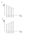
- FIG. 3 is an explanatory diagram showing the gain inclination of signal light composed of a plurality of lights having different wavelengths.
- the vertical axis represents the gain at each wavelength.
- the horizontal axis represents the wavelength of each signal light constituting the signal light.
- FIG. 3 shows gains of signal light having five wavelengths from CH1 to CH5. Also, the gain slope is shown as a dotted line.
- the gain of each wavelength is not measured, but the gain of each wavelength is used for explanation.
- FIG. 3A corresponds to the gain slope for each wavelength in the case of FIG. 2A, and the gain slope value is ( ⁇ 0.4) [dBpp].
- FIG. 3B corresponds to the gain slope in the case of FIG. 2B, and the gain slope value is (0.4) [dBpp].
- FIG. 4 is an explanatory diagram showing a method of suppressing the gain tilt shown in FIG.
- FIG. 4A is a diagram illustrating the gain of each wavelength before the VTEQ 11 is applied.
- the vertical axis represents the gain at each wavelength.
- the horizontal axis represents the wavelength of each signal light constituting the signal light.
- the gain slope is indicated by a dotted line.
- FIG. 4B is a diagram showing the loss slope derived from the gain slope value.
- the horizontal axis shows the wavelength of the signal light
- the vertical axis shows the loss given to the signal light of each wavelength
- the dotted line shows the loss slope.
- FIG. 4C is a diagram illustrating the gain of each wavelength after applying VTEQ11.
- the vertical axis represents the gain at each wavelength.
- the horizontal axis represents the wavelength of each signal light constituting the signal light.
- a dotted line indicates a gain inclination.
- the tilt control unit 22 estimates the gain tilt value corresponding to the target gain obtained from the pumping light control unit 21, using the gain tilt characteristic shown in FIG. That is, as shown in FIG. 2A, if the target gain is 18 [dB], it can be estimated that the gain slope value is ( ⁇ 0.4) [dBpp]. As a result, it can be estimated that the gain slope decreases to the right as shown in FIG.
- the VTEQ 11 is controlled by the tilt control unit 22 and gives loss of loss tilt to the signal light as shown in FIG.
- this line segment is referred to as a loss slope, and the slope is defined as a loss slope value.
- the signal light power is attenuated by the VTEQ 11 by an amount corresponding to the loss slope of each wavelength.
- the gain of each wavelength becomes flat.
- the maximum loss is given to the wavelength of CH1, which is the shortest wavelength
- the minimum loss is given to CH5, which is the longest wavelength.
- CH2 to CH4 a loss corresponding to a line segment passing through the point corresponding to CH1 and the point corresponding to CH5 in FIG. 4B is given.
- the VTEQ 11 gives the loss of the loss slope value to the signal light by using the calculated gain slope value as the loss slope value.
- the loss slope as shown in FIG. 4B, the loss of CH5 is preferably close to 0 from the viewpoint of securing the signal light power. However, even if the loss of CH5 is larger than 0, the loss slope value corresponding to the gain slope value. As long as it is a loss slope due to the above, the gain of each wavelength can be flattened.
- the loss slope value is the gain slope value, but the correspondence between the loss slope and the gain slope may be formulated, or the correspondence may be stored as a data table obtained by measurement. .
- the tilt control unit 22 may control the VTEQ 11 using an operation gain instead of the target gain transmitted from the excitation light control unit 21.
- the gain slope value can be obtained with high accuracy even when the operation gain differs from the target gain.
- the LD 7a may be controlled so that the output signal light power detected by the PD 6b is within the set range.
- the loss slope of the VTEQ 11 is adjusted by the operation gain calculated by (Equation 1) from the input signal light power.
- control time constant of the VTEQ 11 is set longer than the control time constant of the LD controlled by the excitation light control unit 21. The reason is that there is a limit to the response speed when changing the loss gradient of the VTEQ 11, and also preventing the control from being stably converged due to competition with the control when changing the excitation light intensity of the LD. .
- the gain tilt is suppressed by the VTEQ 11, and therefore the wavelength dependency of the gain can be suppressed even with a simple configuration.
- FIG. FIG. 5 is a configuration diagram showing the configuration of the optical amplifying device 200 according to the second embodiment.
- a shape equalizer SEQ: Shape Equalizer 12 is newly provided between the EDF 3a and the VTEQ 11 in the first embodiment.
- SEQ Shape Equalizer
- symbol is attached
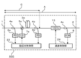
- a section A indicated by a solid double arrow is the same as that in FIG. 1, and a section B indicated by a solid double arrow indicates a section between the light input unit 1 and a dotted downward arrow.
- a dotted line downward arrow indicates a portion between the output terminal of SEQ12 and the input terminal of VTEQ11.
- the section A and the section B are used when comparing an optical amplifying apparatus 200 according to the present embodiment described later and a conventional optical amplifying apparatus.
- SEQ12 is a component having a loss characteristic for compensating a non-linear characteristic that cannot be compensated for by the VTEQ 11 out of the wavelength dependence of the gain of the amplified signal light to make the wavelength dependence a linear characteristic. . Note that, unlike the tilt equalizer 11 in which the loss slope is variable, the SEQ 12 has inherent loss characteristics.
- FIG. 6 is an explanatory diagram for illustrating a method of suppressing the gain tilt by VTEQ11 and SEQ12.
- (a) shows the gain of each wavelength before applying SEQ12.
- (B) shows the gain of each wavelength after applying SEQ12.
- (c) shows the gain of each wavelength after applying SEQ12 and VTEQ11.
- SEQ12 compensates for the non-linear part of the wavelength dependence of gain so that the gain slope is substantially linear. Specifically, (a) including a non-linear component is changed to a substantially linear (b). Next, as shown in (c), the VTEQ 11 reduces the gain slope and flattens the gain slope.
- SEQ12 uses, for example, a diffraction grating such as fiber grading, etalon filter or dielectric multilayer filter.
- the gain tilt is suppressed by the VTEQ 11 and the wavelength-dependent nonlinear component of the gain is compensated by the SEQ 12. Therefore, even when the wavelength dependency of gain is not linear, it is possible to suppress the wavelength dependency of gain.
- FIG. 7 is a configuration diagram of a conventional optical amplifying apparatus 600. 7 is different from the VTEQ 11 in that a variable shape equalizer 13 (VSEQ: Variable Shape Equalizer) is provided, and an optical demultiplexer 4c and an OCM 8 are provided. Further, in the optical amplifying apparatus 200 according to the second embodiment, the PD 6b is provided in the subsequent stage of the VTEQ 11, whereas in the conventional optical amplifying apparatus 600, the PD 6b is provided in the previous stage of the VSEQ 13. .
- a solid line double arrow A is a section from the light input unit 1 to the light output unit 2.
- a solid line double arrow C is a section between the optical input unit 1 and the input end of the VSEQ 13 (indicated by a dotted line downward arrow in the figure).
- the pumping light control unit 23 controls the LD 7a so that the average gain of the signal light in the section C approaches the target gain G1.
- the signal light is demultiplexed by the optical demultiplexer 4 c and input to the OCM 8.
- the OCM 8 measures the signal light power of the wavelength-multiplexed signal light for each wavelength.
- the VSEQ 13 adjusts so that the signal light power of each wavelength output from the light output unit 2 becomes the same level.
- the attenuation controller 24 controls the VSEQ 13 based on the signal light power of each wavelength acquired by the OCM 8 so that the signal light power of each wavelength becomes a constant value.
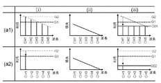
- FIG. 8 is an explanatory diagram showing a control result when the conventional optical amplifying apparatus 600 is used.
- line ( réelle1) indicates a 5-wavelength input state in which signal light of 5 wavelengths CH1 to CH5 is input
- line (b1) indicates a 1-wavelength input state.
- column (i) shows the average gain of section C (shown in FIG. 7), which is a section between optical input unit 1 and VSEQ 13
- column (ii) shows the loss that VSEQ 13 gives to the signal light.
- the column (iii) indicates the average gain in the section A (shown in FIG. 7), which is the section between the optical input unit 1 and the optical output unit 2.
- the dotted line in the horizontal direction indicates the target gain G1 set externally
- the single chain line in the horizontal direction indicates G2 that is the gain of CH1 in the 5-wavelength input state in the section C.
- the (a1) line in FIG. 8 will be described in more detail.
- the pumping light control unit 23 controls the operation gain, which is an average gain in the section C, based on the target gain G1. Therefore, the gain of CH3 and the target gain G1 substantially coincide with each other in (a1) row (i) column. This is because, in FIG. 8, the gain of CH3 substantially matches the average gain of the entire signal light of the five wavelengths CH1 to CH5, and the average gain in the section C is controlled to approach the target gain G1. is there.
- CH1 to CH5 have a lower right gain slope, the gains of CH1 and CH2 are higher than the target gain G1, and the gains of CH4 and CH5 are lower than the target gain G1.
- the column (iii) in the figure shows a state in which the gains of CH1 to CH5 are equal to a constant value after passing through VSEQ13. Since VSEQ13 is a component that causes a loss, the operating gain G01, which is the average gain in the five-wavelength input state in section A, is lower than the target gain G1.
- the average gain of the entire signal light is the target gain G1
- the gain of CH1 is the target gain because there is a gain slope that decreases to the right. It becomes higher than G1.
- the gain of CH1 is controlled to be equal to the target gain G1. Therefore, as indicated by the solid line down arrow in the figure, the gain of CH1 decreases from G2.
- the conventional optical amplifying apparatus 600 has a problem that the operating gain varies greatly when the number of wavelengths of the signal light varies.
- a decrease in gain can be compensated by adjusting VSEQ13.
- control of VSEQ13 is generally slower than constant gain control of EDF. This is because there is a restriction on the response speed of the attenuation component used in VSEQ13. Note that the response speed of the VSEQ 13 controlled by the attenuation controller 24 is low (milliseconds or more), and the response speed of the EDF 3a controlled by the excitation light controller 23 is high (milliseconds or less).
- the operation gain changes that is, the signal light power deviates from the target gain.
- signal light transmitted over a long distance such deviation accumulates as it passes through many optical amplifying devices, which causes deterioration in communication quality. Therefore, in such an optical transmission system, temporary deterioration of communication quality is not allowed, and sacrifice of communication quality until the adjustment of VSEQ 13 is completed is not allowed.
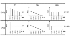
- FIG. 9 is an explanatory diagram illustrating a control result when using the optical amplifying device 200 according to the second embodiment.
- Row (b1) shows a state in which signal light of five wavelengths CH1 to CH5 is inputted
- row (b2) shows a state in which signal light of one wavelength is inputted.
- Column (i) shows the gains of CH1 to CH5 in section B shown in FIG.
- Column (ii) shows the loss of VTEQ11.
- the column (iii) shows the gains of CH1 to CH5 in the section A shown in FIG.
- the dotted line indicates the target gain G1 set outside.
- the gain constant control is performed in the section A by measuring the signal light power on the output side of the VTEQ 11, and therefore, the average gain of the five-wavelength input state in the section A with respect to the target gain G1
- the operating gain G01 and the operating gain G02 that is the average gain in the one-wavelength input state in the section A coincide with each other.
- the operating gain G01 in the 5-wavelength input state in the section A is the same as the operating gain G02 that is the average gain in the 1-wavelength input state. That is, even if the number of wavelengths varies, the average gain of the signal light in the section A does not change.
- This is different from the conventional optical amplifying apparatus 600 shown in FIG. 8 in that the optical demultiplexer 4b is provided not on the input side of the VTEQ 11 but on the output side, and the PD 6b measures the signal light power on the output side of the VTEQ 11. It is.
- the optical amplifying device 200 when the number of wavelengths of signal light changes from 5 wavelengths to 1 wavelength, the optical amplifying device 200 is compared with the conventional optical amplifying device 600 in the average of the section A. There is little fluctuation in gain.
- the optical amplifying apparatus 200 has a configuration in which the PD 6b for measuring the signal light power is appropriately arranged on the output side instead of the input side of the VTEQ 11, and further, the VSEQ 13 that aligns the signal light power of each wavelength.
- the VTEQ 11 is configured to make the gain of each wavelength constant. Therefore, with the above configuration, even when the number of wavelengths varies, the operating gain G01 in the 5-wavelength input state in the section A hardly changes with respect to the operating gain G02 in the 1-wavelength input state. That is, it is possible to appropriately control to suppress the wavelength dependence of the gain and to suppress the significant fluctuation of the operation gain when the wavelength changes.
- the communication quality can be stably maintained even when the wavelength is decreased.
- the conventional optical amplifying apparatus 600 adopts a method of constant gain control and a method of suppressing a gain deviation between wavelengths, and can obtain a desired operation / performance, but operates strictly. Analysis shows that constant gain control with sufficiently high accuracy cannot be realized.
- the optical amplifying device 200 according to Embodiment 2 of the present invention realizes high-precision constant gain control based on accurate analysis. In addition, even if gain wavelength dependence occurs without using an excessively high power / high cost excitation light source, the gain flatness of each wavelength is maintained and high-accuracy constant gain control is realized. To do.
- the optical amplifying apparatus 200 appropriately arranges the optical demultiplexer 4b on the output side of the VTEQ 11, and performs constant gain control using the signal light power on the output side measured by the PD 6b. In addition, it is possible to perform appropriate control even when the number of wavelengths fluctuates by making the gain of signal light having different wavelengths constant, rather than making signal light powers having different wavelengths uniform.
- FIG. FIG. 10 is a configuration diagram showing the configuration of the optical amplifying device 300 according to the third embodiment.
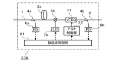
- the wavelength selective optical multiplexer 5a and the LD 7a are provided on the front side of the EDF 3a
- the second The difference is that the wavelength selective optical multiplexer 5b and the LD 7b are provided in the subsequent stage of the EDF 3a.
- the LD 7b excites the EDF 3a in the subsequent stage of the EDF 3a.
- SEQ 12 may be provided between wavelength selective optical multiplexer 5b and VTEQ 11 as in the second embodiment.
- the backward pumping configuration in which the pumping light is multiplexed from the rear stage side of the EDF 3a increases noise degradation as compared with the forward pumping configuration, but the signal light gain saturation is less likely to occur. That is, a higher output can be obtained as compared with forward excitation in which excitation is performed using the LD 5a from the front stage of the EDF 3a.
- components that are the same as or correspond to those in FIG. 1 are given the same reference numerals, and descriptions thereof are omitted.
- FIG. 11 is a configuration diagram illustrating a configuration of the optical amplifying device 400 according to the fourth embodiment.
- the configuration further includes an LD 7b as a pumping light source and a wavelength-selective optical multiplexer 5b provided at the subsequent stage of the EDF 3a.
- the EDF 3a is excited from both the front side and the rear side. Therefore, uniform excitation is possible over the entire length of the EDF 3a.
- SEQ 12 may be provided between wavelength selective optical multiplexer 5b and VTEQ 11 as in the second embodiment. Further, in the figure, the same or corresponding components as those in FIG.
- FIG. 12 is a configuration diagram illustrating a configuration of an optical amplification device 500 according to the fifth embodiment.
- the optical amplifying device 500 according to the fifth embodiment is further provided with an EDF 3b as a second optical amplifying unit in the previous stage of the VTEQ 11 and wavelength selection as compared with the optical amplifying device 400 according to the fourth embodiment.
- a wavelength-selective optical multiplexer 5c as a third optical multiplexer is provided between the EDFs 3a and 3b instead of the optical optical multiplexer 5b.
- the LD 7b pumps the EDF 3b forward via the wavelength selective optical multiplexer 5c.
- SEQ 12 may be provided between the wavelength selective optical multiplexer 5c and the VTEQ 11 as in the second embodiment.
- the same or corresponding components as those in FIG. 11 are denoted by the same reference numerals, and the description thereof is omitted.
- the VTEQ is used to suppress the wavelength dependence of the EDF using the VTEQ.
- the gain of the EDF is fixed to a value that does not cause the wavelength dependence without using the VTEQ.
- the gain value that does not cause wavelength dependency is larger than the required gain, the gain that is required after exciting the EDF so as to obtain a gain that does not cause wavelength dependency once is obtained.
- the gain is attenuated. In this case, an expensive high-power pumping light source is required, and there is a problem that an optical amplifier with high cost and high power consumption is obtained.
- the pumping light intensity of the pumping light source is controlled so that the gain of the optical amplifying device becomes the target gain by measuring the input signal light power and the output signal light power of the optical amplifying device.
- the amplified signal light power is measured immediately after the amplification unit, the pumping light intensity of the pumping light source is controlled using the input signal light power and the amplified signal light power, and then the wavelength dependency of the gain is suppressed.
- the gain of the optical amplifying device is lower than the target gain because the signal light is attenuated when the influence of the wavelength dependency of the gain is suppressed.
- the optical amplifying apparatus of the present invention suppresses fluctuations in gain compared to the conventional optical amplifying apparatus.
- the present invention is not limited to the configuration of the second embodiment, and the first embodiment or the embodiment of the present invention. It goes without saying that the same effect can be obtained even with the configuration of the third to fifth embodiments.
- the optical amplifying apparatus may be configured by appropriately changing the configuration obtained by the combination of the embodiments.
Landscapes
- Physics & Mathematics (AREA)
- Electromagnetism (AREA)
- Engineering & Computer Science (AREA)
- Plasma & Fusion (AREA)
- Optics & Photonics (AREA)
- Computer Networks & Wireless Communication (AREA)
- Signal Processing (AREA)
- Automation & Control Theory (AREA)
- Lasers (AREA)
Abstract
Description
図1は、実施の形態1に係る光増幅装置100の構成を示す構成図である。図1において、光増幅装置100は、入力された信号光を増幅する光増幅部を有する信号光伝搬路10と、光源素子と受光素子からなる複数の光学素子部品と、光増幅装置100の構成部品を制御する制御部とから構成されている。
動作利得(dB)=10Log(Po/Pi)・・・(式1)
図5は、実施の形態2に係る光増幅装置200の構成を示す構成図である。実施の形態2に係る光増幅装置200では、実施の形態1にEDF3aとVTEQ11との間にシェイプ等化器(SEQ:Shape EQualizer)12が新たに設けられている。なお、実施の形態1と同一もしくは対応する構成については、同一符号を付し、その説明を省略する。
図10は、実施の形態3に係る光増幅装置300の構成を示す構成図である。実施の形態1に係る光増幅装置100では、波長選択性光合波器5a及びLD7aがEDF3aの前段側に設けられているのに対して、実施の形態3に係る光増幅装置300では、第2の光合波部としての波長選択性光合波器5b及びLD7bがEDF3aの後段に設けられている点が異なる。ここで、LD7bは、EDF3aの後段においてEDF3aを励起している。なお、実施の形態2と同様に、波長選択性光合波器5bとVTEQ11との間にSEQ12を設けてもよいことは言うまでもない。
図11は、実施の形態4に係る光増幅装置400の構成を示す構成図である。実施の形態1に係る光増幅装置100の構成に加えて、EDF3aの後段に設けられる励起光源としてのLD7b及び波長選択性光合波器5bをさらに備える構成である。EDF3aは、前段側と後段側の両方から励起される。そのため、EDF3a全長に亘って均一な励起が可能となる。なお、実施の形態2と同様に、波長選択性光合波器5bとVTEQ11との間にSEQ12を設けてもよいことは言うまでもない。また、図中、図1と同一もしくは対応する構成については、同一符号を付し、その説明を省略する。
図12は、実施の形態5に係る光増幅装置500の構成を示す構成図である。実施の形態5に係る光増幅装置500は、実施の形態4に係る光増幅装置400と比較して、第2の光増幅部としてのEDF3bがVTEQ11の前段にさらに設けられていると共に、波長選択性光合波器5bの代わりに、第3の光合波部としての波長選択性光合波器5cがEDF3a,3bの間に設けられている点が異なる。ここでは、LD7bは、波長選択性光合波器5cを介してEDF3bを前方励起している。なお、実施の形態2と同様に、波長選択性光合波器5cとVTEQ11との間にSEQ12を設けてもよいことは言うまでもない。また、図中、図11と同一もしくは対応する構成については、同一符号を付し、その説明を省略する。
2 光出力部
3a,3b EDF(エルビウム添加ファイバ)
5a,5b,5c 波長選択性光合波器
6a,6b PD(フォトダイオード)
7a,7b LD(レーザダイオード)
10 信号光伝搬路
11 VTEQ(可変チルト等化器)
12 SEQ(シェイプ等化器)
21 励起光制御部
22 チルト制御部
Claims (10)
- 互いに異なる波長を有する複数の信号光が多重化された入力信号光が入力される光入力部と、前記入力信号光を増幅し増幅信号光として出力する第1の光増幅部と、前記増幅信号光が出力される光出力部と、を有する信号光伝搬路を備え、
前記信号光伝搬路は、前記第1の光増幅部と前記光出力部との間に設けられ、前記増幅信号光に対して直線的な損失傾斜による損失を与え、前記損失傾斜の傾きである損失傾斜値を変更可能である可変チルト等化器を有する光増幅装置であって、
前記光入力部における入力信号光パワーを検出する第1の光検出器と、
前記第1の光増幅部を励起する励起光源と、
前記光出力部における出力信号光パワーを検出する第2の光検出器と、
前記励起光源を制御する第1の制御部と、
前記可変チルト等化器の前記損失傾斜値を制御する第2の制御部と
を備える光増幅装置。 - 前記第1の制御部は、
前記入力信号光パワー及び前記出力信号光パワーに基づいて動作利得を求め、前記動作利得が予め設定された目標利得に近付くように前記励起光源を制御する
ことを特徴とする請求項1に記載の光増幅装置。 - 前記第2の制御部は、
前記第1の光増幅部の利得の波長依存性である利得傾斜特性及び前記目標利得に基づき利得傾斜の傾きである利得傾斜値を算出し、前記利得傾斜値を前記損失傾斜値として前記可変チルト等化器を制御する
ことを特徴とする請求項2に記載の光増幅装置。 - 前記第2の制御部は、
前記第1の光増幅部の利得の波長依存性である利得傾斜特性及び前記動作利得に基づき利得傾斜の傾きである利得傾斜値を算出し、前記利得傾斜値を前記損失傾斜値として前記可変チルト等化器を制御する
ことを特徴とする請求項2に記載の光増幅装置。 - 前記信号光伝搬路は、
前記第1の光増幅部と前記可変チルト等化器との間に設けられ、前記利得傾斜を直線的な特性に補償する損失特性を有するシェイプ等化器を有する
ことを特徴とする請求項3または請求項4に記載の光増幅装置。 - 前記信号光伝搬路は、
前記光入力部と前記第1の光増幅部との間に設けられた第1の光合波部を有し、
前記励起光源は、
前記第1の光合波部を介して前記第1の光増幅部を励起する
ことを特徴とする請求項1から請求項5のいずれか1項に記載の光増幅装置。 - 前記信号光伝搬路は、
前記第1の光増幅部と前記可変チルト等化器との間に第2の光合波部を有し、
前記励起光源は、
前記第2の光合波部を介して前記第1の光増幅部を励起する
ことを特徴とする請求項1から請求項5のいずれか1項に記載の光増幅装置。 - 前記信号光伝搬路は、
前記光入力部と前記第1の光増幅部との間に設けられた第1の光合波部と、
前記第1の光増幅部と前記可変チルト等化器との間に設けられた第2の光合波部と
を有し、
前記励起光源は、
前記第1の光合波部及び前記第2の光合波部を介して前記第1の光増幅部を励起する
ことを特徴とする請求項1から請求項5のいずれか1項に記載の光増幅装置。 - 前記信号光伝搬路は、
前記光入力部と前記第1の光増幅部との間に設けられた第1の光合波部と、
前記第1の光増幅部と前記可変チルト等化器との間に設けられた第3の光合波部と、
前記第3の光合波部と前記可変チルト等化器との間に設けられた第2の光増幅部と
を有し、
前記励起光源は、
前記第1の光合波部を介して前記第1の光増幅部を励起すると共に、前記第3の光合波部を介して前記第2の光増幅部を励起する
ことを特徴とする請求項1から請求項5のいずれか1項に記載の光増幅装置。 - 前記第1の制御部の制御周期は、前記第2の制御部の周期より短い
ことを特徴とする請求項1から請求項9のいずれか1項に記載の光増幅装置。
Priority Applications (5)
| Application Number | Priority Date | Filing Date | Title |
|---|---|---|---|
| US15/774,019 US10971888B2 (en) | 2015-11-19 | 2015-11-19 | Optical amplifier |
| JP2017551453A JPWO2017085822A1 (ja) | 2015-11-19 | 2015-11-19 | 光増幅装置 |
| PCT/JP2015/082484 WO2017085822A1 (ja) | 2015-11-19 | 2015-11-19 | 光増幅装置 |
| CN201580084532.0A CN108352672A (zh) | 2015-11-19 | 2015-11-19 | 光放大装置 |
| EP15908762.6A EP3379662B1 (en) | 2015-11-19 | 2015-11-19 | Optical amplifier |
Applications Claiming Priority (1)
| Application Number | Priority Date | Filing Date | Title |
|---|---|---|---|
| PCT/JP2015/082484 WO2017085822A1 (ja) | 2015-11-19 | 2015-11-19 | 光増幅装置 |
Publications (1)
| Publication Number | Publication Date |
|---|---|
| WO2017085822A1 true WO2017085822A1 (ja) | 2017-05-26 |
Family
ID=58718625
Family Applications (1)
| Application Number | Title | Priority Date | Filing Date |
|---|---|---|---|
| PCT/JP2015/082484 Ceased WO2017085822A1 (ja) | 2015-11-19 | 2015-11-19 | 光増幅装置 |
Country Status (5)
| Country | Link |
|---|---|
| US (1) | US10971888B2 (ja) |
| EP (1) | EP3379662B1 (ja) |
| JP (1) | JPWO2017085822A1 (ja) |
| CN (1) | CN108352672A (ja) |
| WO (1) | WO2017085822A1 (ja) |
Families Citing this family (3)
| Publication number | Priority date | Publication date | Assignee | Title |
|---|---|---|---|---|
| WO2020194860A1 (ja) * | 2019-03-25 | 2020-10-01 | 日本電気株式会社 | 光等化器、方法及び非一時的なコンピュータ可読媒体 |
| CN110601766B (zh) * | 2019-09-10 | 2020-11-13 | 武汉光迅科技股份有限公司 | 一种控制方法及光纤放大器 |
| US20240258758A1 (en) * | 2023-01-26 | 2024-08-01 | Fujitsu Limited | Optical signal amplification |
Citations (3)
| Publication number | Priority date | Publication date | Assignee | Title |
|---|---|---|---|---|
| JP2000252923A (ja) * | 1999-03-02 | 2000-09-14 | Fujitsu Ltd | 波長多重用光増幅器及び光通信システム |
| JP2003526215A (ja) * | 2000-03-03 | 2003-09-02 | テレフオンアクチーボラゲツト エル エム エリクソン | 光増幅器内の利得制御 |
| JP2006286918A (ja) | 2005-03-31 | 2006-10-19 | Furukawa Electric Co Ltd:The | 光増幅装置 |
Family Cites Families (15)
| Publication number | Priority date | Publication date | Assignee | Title |
|---|---|---|---|---|
| JP3306700B2 (ja) | 1996-05-02 | 2002-07-24 | 富士通株式会社 | 光増幅装置及び波長多重光伝送システム |
| US6728026B2 (en) * | 1998-07-14 | 2004-04-27 | Novera Optics, Inc. | Dynamically tunable optical amplifier and fiber optic light source |
| US6456428B1 (en) * | 1999-09-02 | 2002-09-24 | Sumitomo Electric Industries, Ltd. | Optical amplifier |
| US6535329B1 (en) * | 1999-12-20 | 2003-03-18 | Jds Uniphase Inc. | Temperature tuning an optical amplifier |
| US6731424B1 (en) * | 2001-03-15 | 2004-05-04 | Onetta, Inc. | Dynamic gain flattening in an optical communication system |
| US6611371B2 (en) | 2001-03-16 | 2003-08-26 | Corning Incorporated | Single parameter gain slope adjuster for an optical system |
| US6535330B1 (en) * | 2001-03-31 | 2003-03-18 | Corning Incorporated | Dynamic controller for a multi-channel optical amplifier |
| US6483631B1 (en) * | 2001-06-05 | 2002-11-19 | Onetta, Inc. | Optical amplifier spectral tilt controllers |
| GB0124258D0 (en) | 2001-10-09 | 2001-11-28 | Marconi Comm Ltd | Optical amplifier control in WDM communications systems |
| JP3903830B2 (ja) * | 2002-04-05 | 2007-04-11 | 株式会社日立製作所 | 利得補償装置及びそれを用いた伝送システム |
| JP3551418B2 (ja) | 2003-05-27 | 2004-08-04 | 富士通株式会社 | 光伝送装置及び波長多重光通信システム |
| JP4298570B2 (ja) * | 2004-04-13 | 2009-07-22 | 富士通株式会社 | 光ファイバ増幅器の制御方法および光伝送システム |
| JP2006108499A (ja) | 2004-10-07 | 2006-04-20 | Furukawa Electric Co Ltd:The | 光信号増幅装置及びロススペクトルの決定方法。 |
| US8233214B2 (en) * | 2008-02-13 | 2012-07-31 | Maxim Bolshtyansky | Optical fiber amplifier and a control method therefor |
| JP2012156285A (ja) * | 2011-01-26 | 2012-08-16 | Fujitsu Ltd | 光増幅装置 |
-
2015
- 2015-11-19 US US15/774,019 patent/US10971888B2/en active Active
- 2015-11-19 WO PCT/JP2015/082484 patent/WO2017085822A1/ja not_active Ceased
- 2015-11-19 CN CN201580084532.0A patent/CN108352672A/zh active Pending
- 2015-11-19 EP EP15908762.6A patent/EP3379662B1/en active Active
- 2015-11-19 JP JP2017551453A patent/JPWO2017085822A1/ja active Pending
Patent Citations (3)
| Publication number | Priority date | Publication date | Assignee | Title |
|---|---|---|---|---|
| JP2000252923A (ja) * | 1999-03-02 | 2000-09-14 | Fujitsu Ltd | 波長多重用光増幅器及び光通信システム |
| JP2003526215A (ja) * | 2000-03-03 | 2003-09-02 | テレフオンアクチーボラゲツト エル エム エリクソン | 光増幅器内の利得制御 |
| JP2006286918A (ja) | 2005-03-31 | 2006-10-19 | Furukawa Electric Co Ltd:The | 光増幅装置 |
Non-Patent Citations (1)
| Title |
|---|
| See also references of EP3379662A4 |
Also Published As
| Publication number | Publication date |
|---|---|
| US20180358775A1 (en) | 2018-12-13 |
| EP3379662A4 (en) | 2018-12-05 |
| CN108352672A (zh) | 2018-07-31 |
| JPWO2017085822A1 (ja) | 2018-06-28 |
| EP3379662B1 (en) | 2025-04-09 |
| EP3379662A1 (en) | 2018-09-26 |
| US10971888B2 (en) | 2021-04-06 |
Similar Documents
| Publication | Publication Date | Title |
|---|---|---|
| US7359112B2 (en) | Individual band gain equalizer for optical amplifiers | |
| CN101414731B (zh) | 用于平坦光放大器增益谱的装置和方法 | |
| JP3903650B2 (ja) | 光増幅器および光増幅器制御方法 | |
| US7715092B2 (en) | Dynamic raman tilt compensation | |
| JP5089723B2 (ja) | 波長多重励起ラマンアンプ、波長多重励起ラマンアンプの制御方法および制御プログラム | |
| JPH08278523A (ja) | 光増幅装置 | |
| JP5239141B2 (ja) | 光増幅装置およびその制御方法 | |
| US8351112B2 (en) | Optical amplifier | |
| JP5471227B2 (ja) | 光増幅器及び光増幅方法 | |
| WO2017085822A1 (ja) | 光増幅装置 | |
| JP2001094181A (ja) | 光増幅器 | |
| JP2004301991A (ja) | 光増幅制御ユニットおよび光増幅制御方法 | |
| JP3811134B2 (ja) | 光増幅器 | |
| JP4281245B2 (ja) | 光増幅器 | |
| JP6020640B2 (ja) | 光増幅装置 | |
| JP5682677B2 (ja) | 光増幅器及び光増幅方法 | |
| JP5304378B2 (ja) | 光増幅器 | |
| JP5759437B2 (ja) | 光増幅器システム及び光増幅方法 | |
| JP2006286918A (ja) | 光増幅装置 | |
| JP5142024B2 (ja) | 光増幅装置 | |
| JP3902214B2 (ja) | 光伝送装置 | |
| JP2001196673A (ja) | 光ファイバ増幅器 | |
| JP2004273573A (ja) | 光増幅器および光通信システム | |
| JP2007067424A (ja) | 光伝送装置 |
Legal Events
| Date | Code | Title | Description |
|---|---|---|---|
| 121 | Ep: the epo has been informed by wipo that ep was designated in this application |
Ref document number: 15908762 Country of ref document: EP Kind code of ref document: A1 |
|
| ENP | Entry into the national phase |
Ref document number: 2017551453 Country of ref document: JP Kind code of ref document: A |
|
| NENP | Non-entry into the national phase |
Ref country code: DE |
|
| WWE | Wipo information: entry into national phase |
Ref document number: 2015908762 Country of ref document: EP |
|
| WWG | Wipo information: grant in national office |
Ref document number: 2015908762 Country of ref document: EP |